Embed Size (px)
Citation preview

Moldex3D, Structural Analysis, and HyperStudy
Integrated in HyperWorks Platform
Anthony Yang
Moldex3D

CoreTech System and Moldex3D
The world’s largest injection molding CAE ISV
80% experienced engineering professionals
50% of employees involved in R&D activities
9 global offices, local support from Michigan
1,200+ global customers
6,000+ industrial projects validation

1,200+ Global Customers in various industry
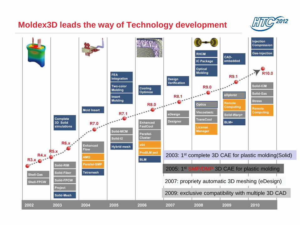
Moldex3D leads the way of Technology development
2003: 1st complete 3D CAE for plastic molding(Solid)
2005: 1st SMP/DMP 3D CAE for plastic molding
2007: propriety automatic 3D meshing (eDesign)
2009: exclusive compatibility with multiple 3D CAD

How Moldex3D Can Help? Aesthetics and dimensional concerns
Weld line, air trap, flow mark
Flow balance and part weight
shrinkage and warpage control
Fiber orientation
Being more competitive
Cycle time reduction by removing
hot & cold spots
Mold structure optimization
Reduce mold trial & tooling cost
Reaching Lean Production
Injection conditions optimization
Clamping force reduction
Machine selection

Moldex3D Flow Analysis
Moldex3D-Flow predicts melt front, weld line, air trap,
short shot and process window…
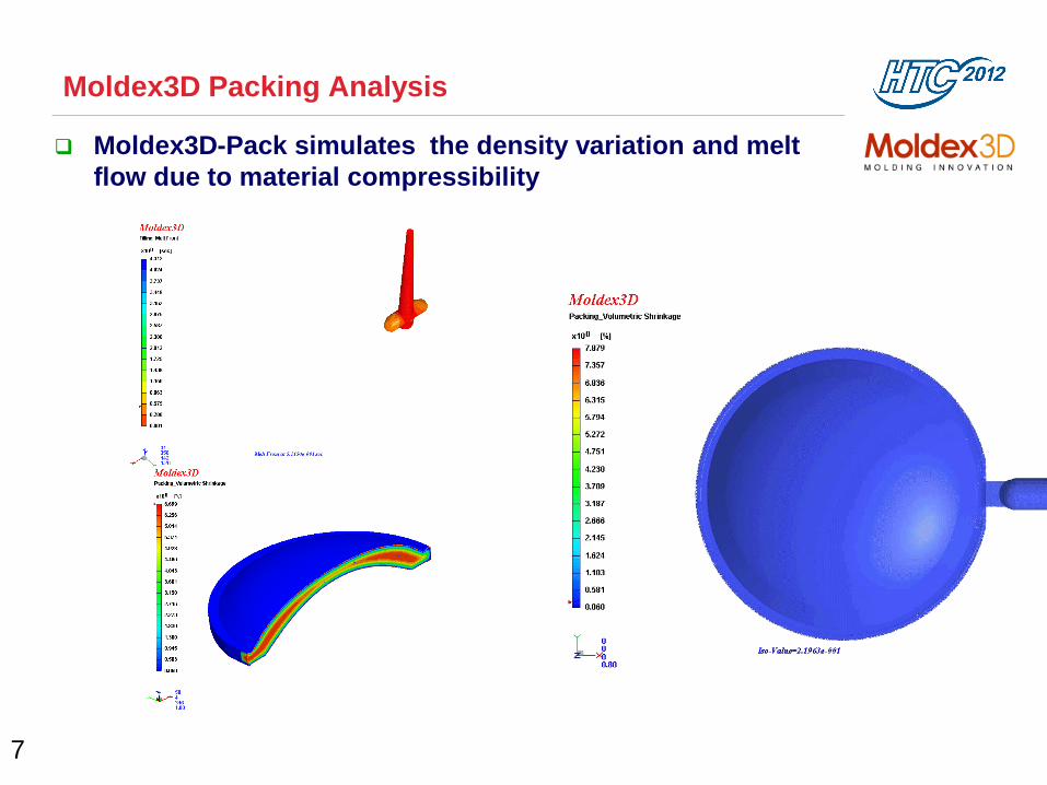
Moldex3D Packing Analysis
7
Moldex3D-Pack simulates the density variation and melt
flow due to material compressibility
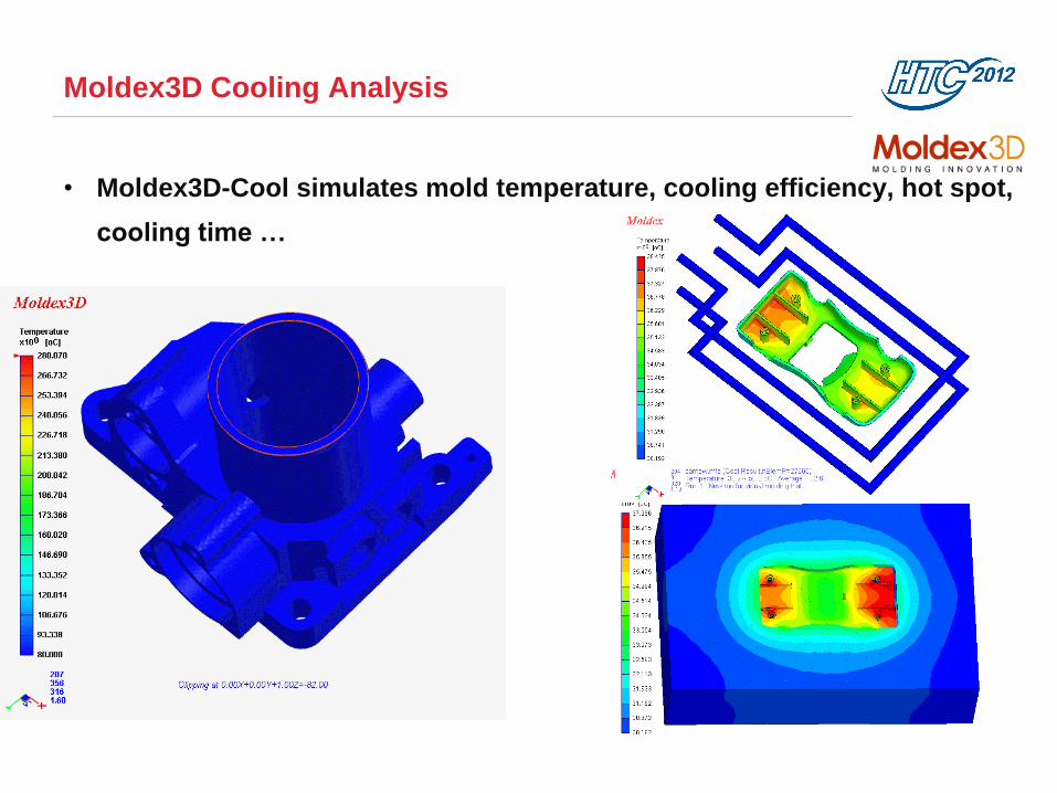
Moldex3D Cooling Analysis
• Moldex3D-Cool simulates mold temperature, cooling efficiency, hot spot,
cooling time …

Moldex3D Warpage Analysis
Moldex3D-Warp simulates the part warpage due to volumetric shrinkage
and further help to control these defects before mold is built
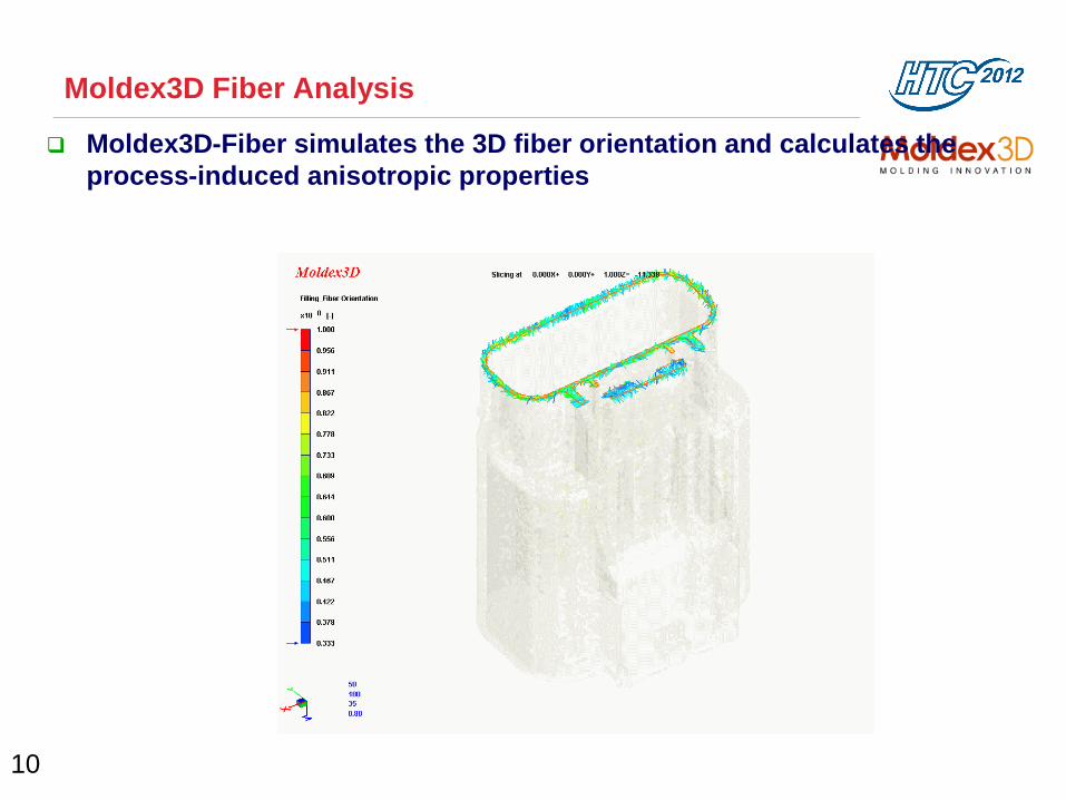
Moldex3D Fiber Analysis
10
Moldex3D-Fiber simulates the 3D fiber orientation and calculates the
process-induced anisotropic properties

MCM Analysis in Moldex3D
Moldex3D-MCM simulates the Multi-Component Molding, Insert molding
and over molding process.

Exclusive Moldex3D Features
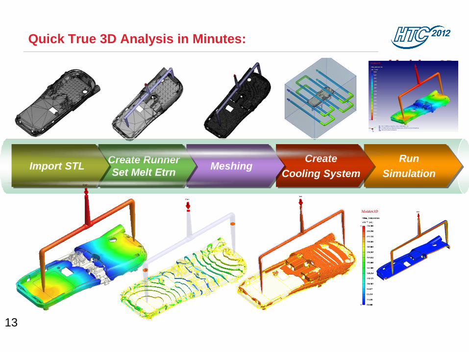
Quick True 3D Analysis in Minutes:
13
Run
Simulation
Create
Cooling System Meshing
Create Runner
Set Melt Etrn Import STL
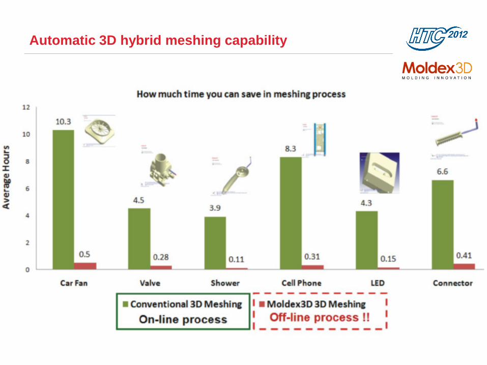
Automatic 3D hybrid meshing capability

eDesign:
Intelligent Gate Wizard

eDesign:
Intelligent Runner Wizard

Accuracy - by running FULL 3D analysis
High temperature resolution in runners

eDesign:
Intelligent Cooling System Wizard
Support the ALL cooling
system in 3D

SMP/DMP Parallel Computing with excellent
acceleration ratio
19
Moldex3D R9.1 Solid-Flow Parallel Computing Performance on an Intel Core i7 Cluster - Speed Up Ratio
1.00
2.01
4.00
6.98
10.40
1.00
1.89
3.65
6.81
10.92
1.00
7.64
11.75
0.00 4.00 8.00 12.00 16.00
1 Core (1 CPU)
2 Cores (2 CPUs)
4 Cores (4 CPUs)
8 Cores (4 CPUs)
16 Cores (4 CPUs)
Speep Up Ratio
Car Grill (elements: 713,558, R9.1 Solid-Flow Enhanced)16-cavity Lens (elements: 1,066,448, R9.1 Solid-Flow Standard)Tray (elements: 1,422,416, R9.1 Solid-Flow Standard)
Benchmark Hardware - One BoxClusterNX (www.boxcluster.com)
- 4-node PC cluster
- one Intel Core i7 940 CPU on each node
- 12 GB DDR3 RAM on each node
- Gigabit network

Moldex3D Application Examples
20

BASF – New material development for automotive
bumper
Füllverhalten bei 50% Füllung
Füllverhalten bei 75% Füllung
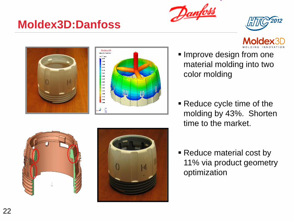
Moldex3D:Danfoss
22
Improve design from one
material molding into two
color molding
Reduce cycle time of the
molding by 43%. Shorten
time to the market.
Reduce material cost by
11% via product geometry
optimization
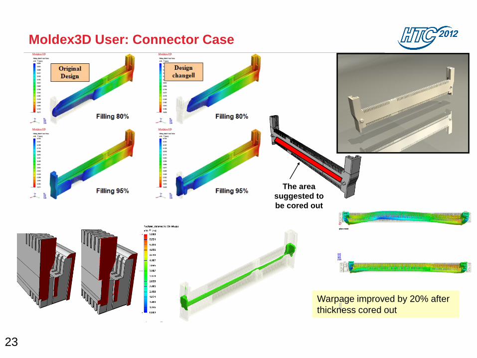
Moldex3D User: Connector Case
23
The area
suggested to
be cored out
Warpage improved by 20% after
thickness cored out

Moldex3D User: Unilever
24
Temperature difference :45oC ->15oC
Cooling time reduced by 25% (from 5 to 3 sec)
Save 4 million sec

FEA Integration Analysis
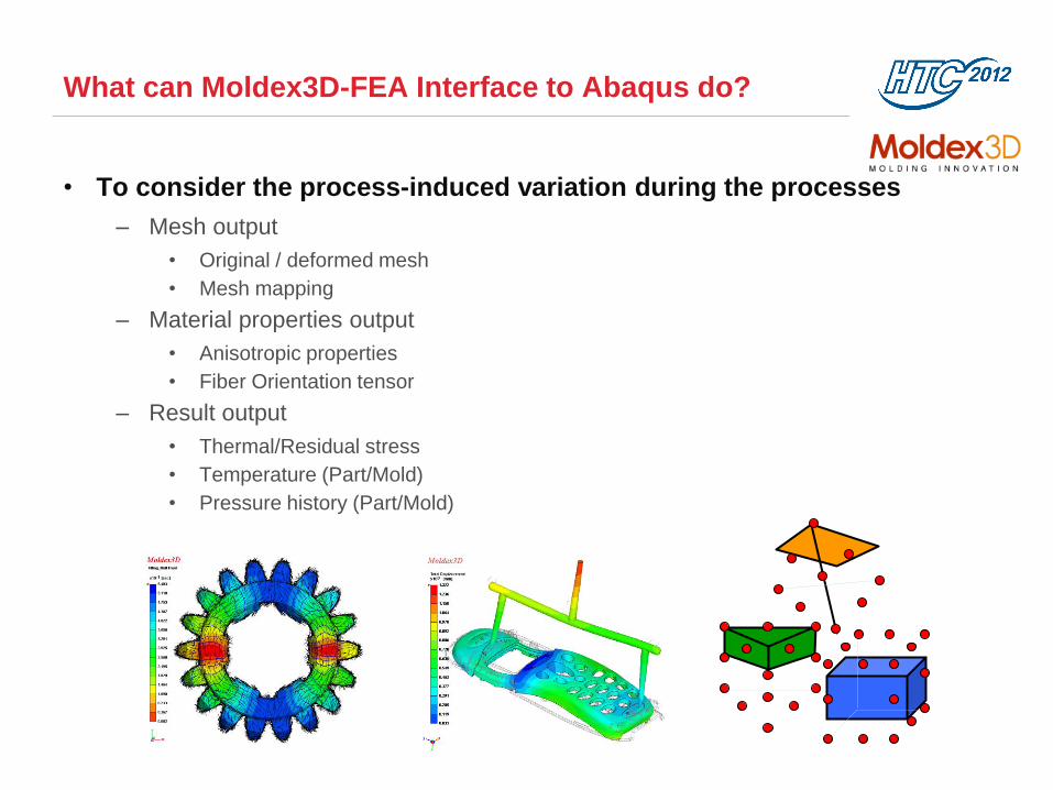
What can Moldex3D-FEA Interface to Abaqus do?
• To consider the process-induced variation during the processes
– Mesh output
• Original / deformed mesh
• Mesh mapping
– Material properties output
• Anisotropic properties
• Fiber Orientation tensor
– Result output
• Thermal/Residual stress
• Temperature (Part/Mold)
• Pressure history (Part/Mold)
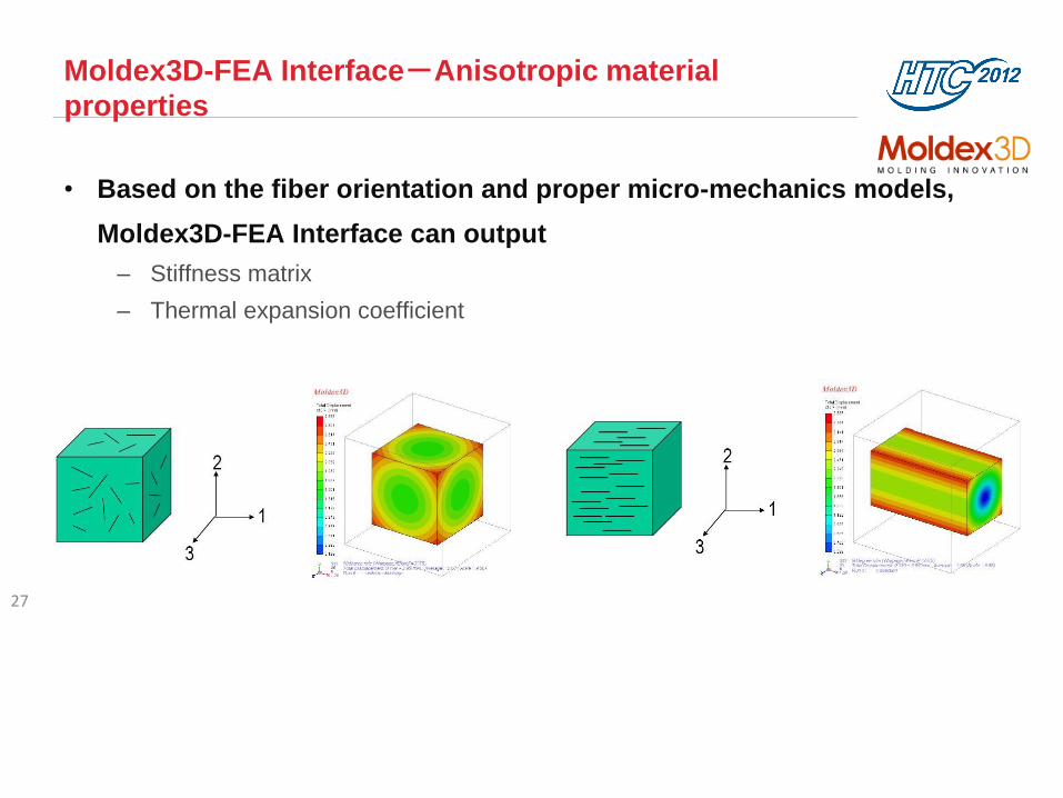
Moldex3D-FEA Interface-Anisotropic material
properties
• Based on the fiber orientation and proper micro-mechanics models,
Moldex3D-FEA Interface can output
– Stiffness matrix
– Thermal expansion coefficient
27
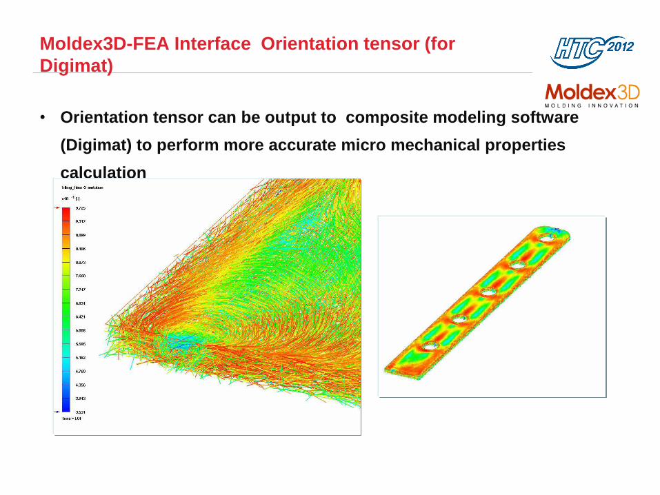
Moldex3D-FEA Interface Orientation tensor (for
Digimat)
• Orientation tensor can be output to composite modeling software
(Digimat) to perform more accurate micro mechanical properties
calculation

Moldex3D-FEA Interface-Material Reduction
• Material Reduction
– Moldex3-FEA Interface can reduce the anisotropy scale by homogenizing the
similar anisotropic properties so as to improve the computational efficiency
29
Total material number from
76,150 to 1,866
Total material number from
3,392 to 668

Technology Link of FEA Interface
Flow Pack Cool Warp
Moldex3D Simulation Ejection Application
Warpage
Structure
Analysis
Mold Deform
Core-Shift
Paddle-Shift
Modal Analysis
Drop Test
Impact
FEA-MSC
Marc
FEA-
ANSYS
FEA-
ABAQUS
FEA-MSC
Nastran
FEA
LS-DYNA
FEA-NX
Nastran
FEA-
RADIOSS
Structural

Moldex3D-FEA Interface-Interface to Abaqus
1. Click FEA
Interface Icon
2. Select Abaqus Solver
4. Select output
data
5. Export .inp file
3. Select output meshtype
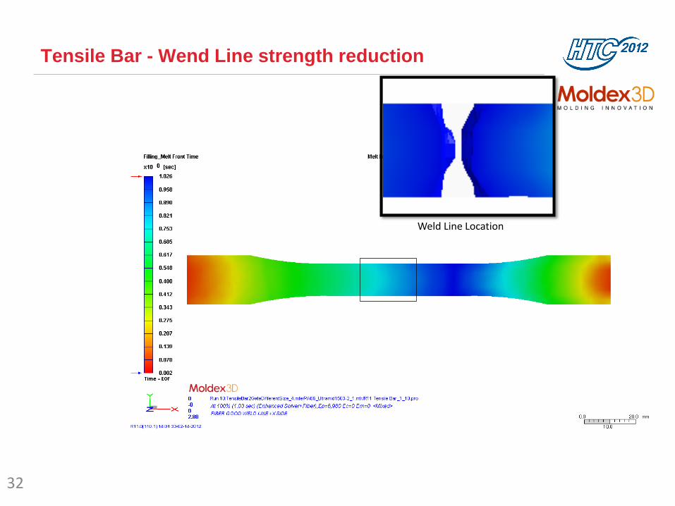
Tensile Bar - Wend Line strength reduction
32
Weld Line Location
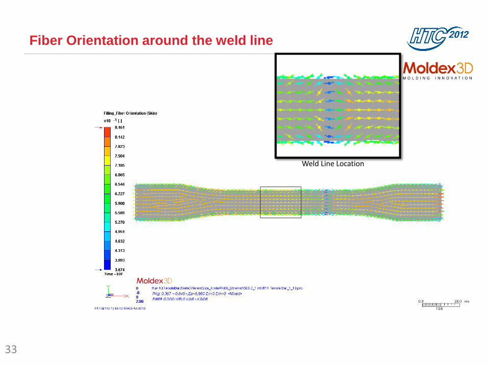
Fiber Orientation around the weld line
33
Weld Line Location
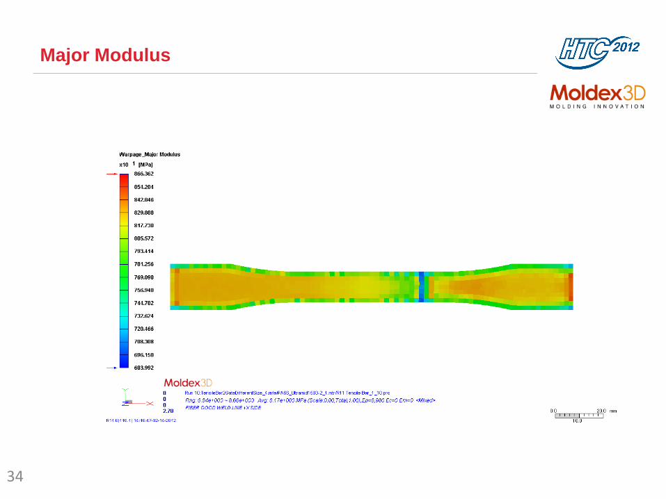
Major Modulus
34
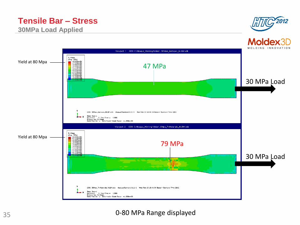
Tensile Bar – Stress 30MPa Load Applied
35
Yield at 80 Mpa
Yield at 80 Mpa
79 MPa
47 MPa
30 MPa Load
30 MPa Load
0-80 MPa Range displayed
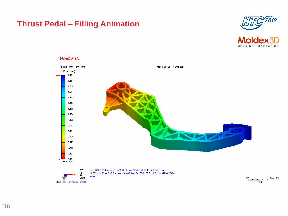
Thrust Pedal – Filling Animation
36
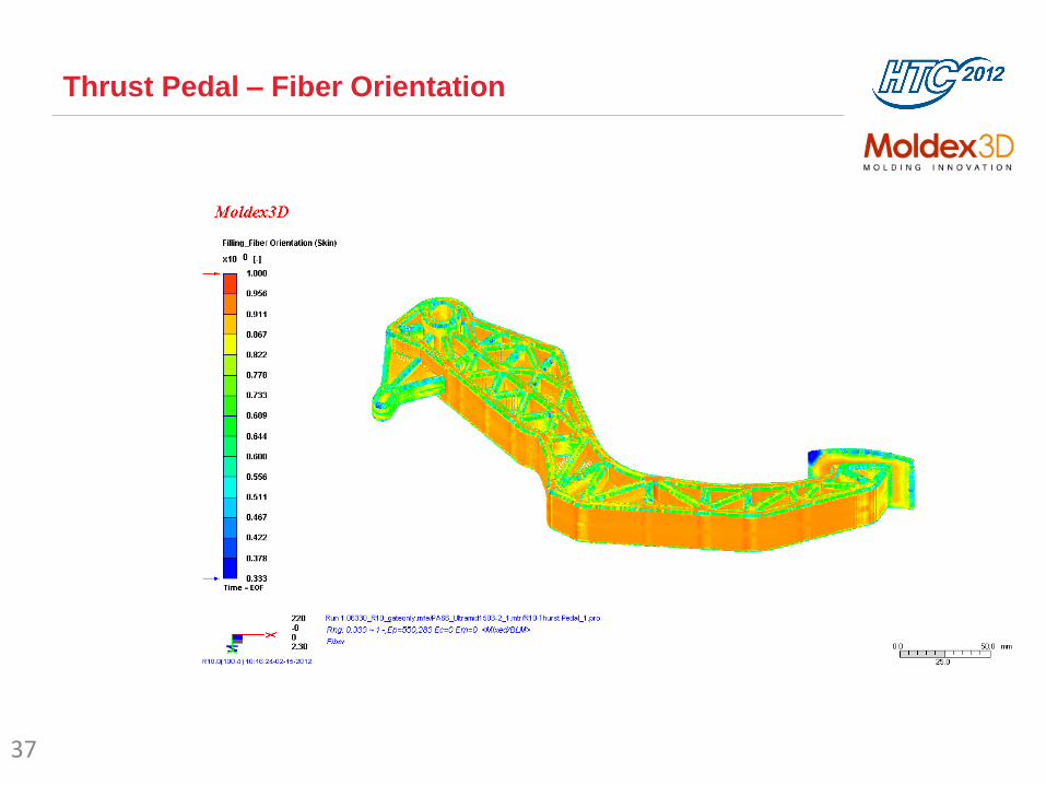
Thrust Pedal – Fiber Orientation
37
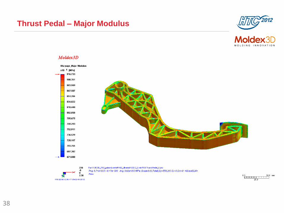
Thrust Pedal – Major Modulus
38

Thrust Pedal – Minor Modulus
39

Thrust Pedal – Model Setup
40
Apply a force on the Pedal
Fix the pin slot

Thrust Pedal – Displacement & Stress
200lbf (900 N) Force Applied
41
Displacement Stress
0-50 mm range 0-100 MPa range
isotropic
anisotropic

Integration between Moldex3D and
HyperStudy
Improving Part Quality for Injection
Molding

Introduction: Moldex3D and HyperStudy
• Moldex3D
• Moldex3D is the world leading CAE product for the plastics injection molding
industry
• HyperStudy
• HyperStudy is software to perform Design of Experiments (DOE), optimization,
and stochastic studies in a CAE environment
• HyperStudy is a member of the HyperWorks suite of software products
• Benefits of Moldex3D and HyperStudy Integration
• Users can employ HyperStudy to perform a series of Moldex3D analyses
systematically for improving part qualities
• Process conditions can be optimized automatically
• Moldex3D supports all study types for HyperStudy

Workflow between Moldex3D and HyperStudy
Do Study setup, DOE setup and
others setups Copy new design factor file and
call Moldex3D as the solver
through script function
Output response factor
Finish all runs and obtain optimal results
Create an initial run and perform a preliminary analysis

Integrating Moldex3D and HyperStudy:
DOE Study

Case Study
• An injection molded part from a speed meter shows potential warpage
problem from preliminary Moldex3D analyses.
• Dimension: 400 x 126 x 76 mm
• The target is to reduce warpage through optimizing process conditions
with HyperStudy and Moldex3D using DOE study.
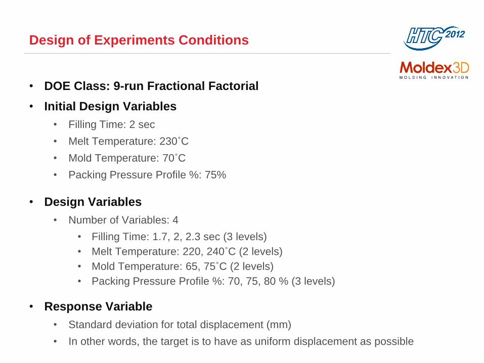
Design of Experiments Conditions
• DOE Class: 9-run Fractional Factorial
• Initial Design Variables
• Filling Time: 2 sec
• Melt Temperature: 230˚C
• Mold Temperature: 70˚C
• Packing Pressure Profile %: 75%
• Design Variables
• Number of Variables: 4
• Filling Time: 1.7, 2, 2.3 sec (3 levels)
• Melt Temperature: 220, 240˚C (2 levels)
• Mold Temperature: 65, 75˚C (2 levels)
• Packing Pressure Profile %: 70, 75, 80 % (3 levels)
• Response Variable
• Standard deviation for total displacement (mm)
• In other words, the target is to have as uniform displacement as possible
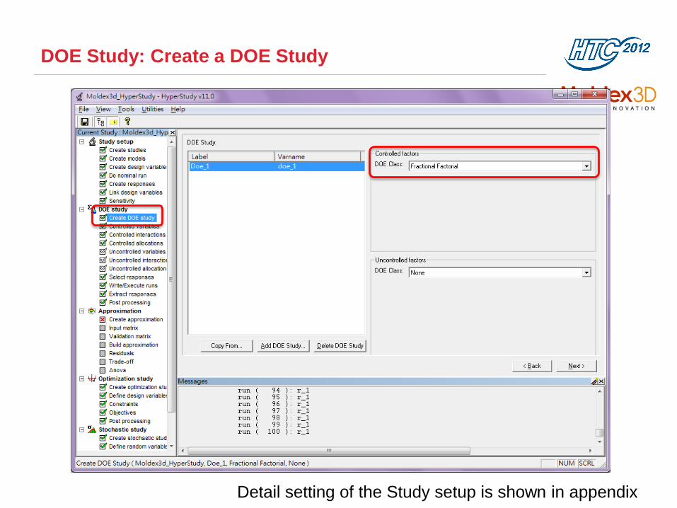
DOE Study: Create a DOE Study
Select DOE Class
Detail setting of the Study setup is shown in appendix
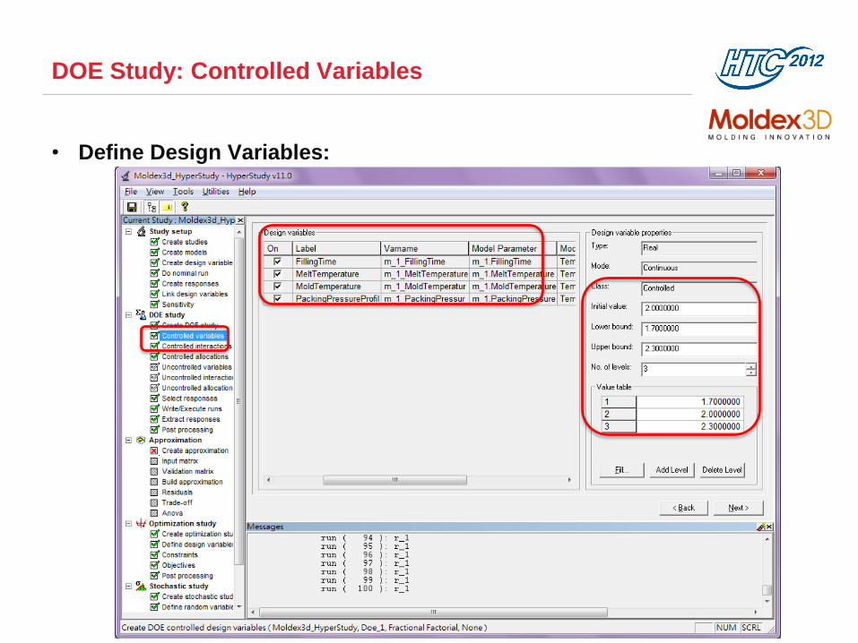
DOE Study: Controlled Variables
• Define Design Variables:
Select Design variables
Setup Design variable
bounds and level values

DOE Study: DOE Run Table

Design of Experiments: Run Results
Run Summary
Main Effects
This chart indicates the melt
temperature and packing
pressure profile are the most
sensitive factors
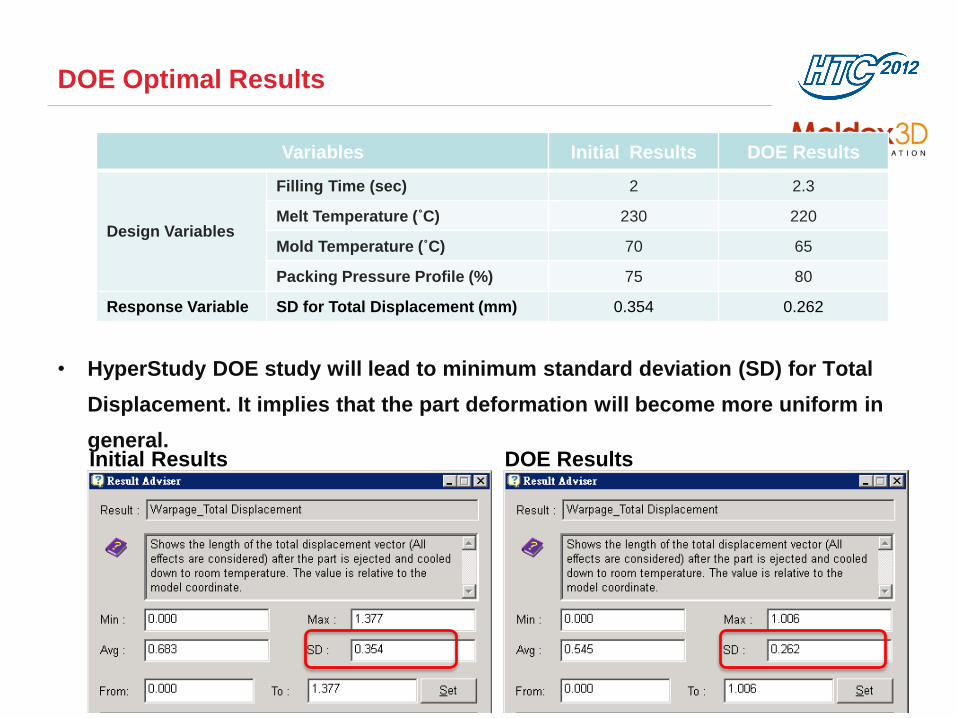
DOE Optimal Results
• HyperStudy DOE study will lead to minimum standard deviation (SD) for Total
Displacement. It implies that the part deformation will become more uniform in
general.
Variables Initial Results DOE Results
Design Variables
Filling Time (sec) 2 2.3
Melt Temperature (˚C) 230 220
Mold Temperature (˚C) 70 65
Packing Pressure Profile (%) 75 80
Response Variable SD for Total Displacement (mm) 0.354 0.262
Initial Results DOE Results

Integrating Moldex3D and HyperStudy:
Optimization Study
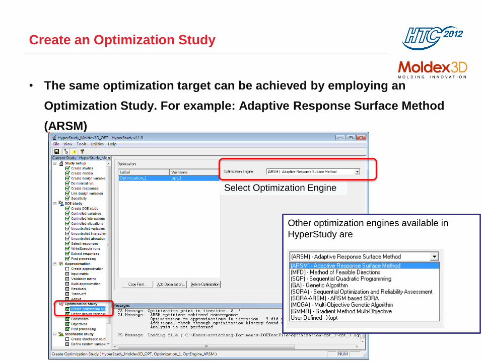
Create an Optimization Study
• The same optimization target can be achieved by employing an
Optimization Study. For example: Adaptive Response Surface Method
(ARSM)
Select Optimization Engine
Other optimization engines available in
HyperStudy are

Optimization Study: Define Design Variables
• Define Design Variables:
• Filling Time (Range: 1.7, 2.3 sec)
• Melt Temperature (Range: 220, 240˚C)
• Mold Temperature (Range: 65, 75˚C)
• Packing Pressure Profile % (Range: 70, 80 %)

Settings for Objectives
• Objectives:
• Goal: Minimum Standard Deviation (SD) for Total Displacement
• Maximum Iterations: 20
• Absolute Convergence: 0.001
• Relative Convergence: 1.0%

Optimal Results
History Plot
History Table
Optimized design factors

Optimal Results
• Recommended optimal results will lead to the minimum standard deviation (SD)
for Total Displacement. It means that the part deformation will become more
uniform in general.
Variables Initial Run Optimal Run
Design Variables
Filling Time (sec) 2 2.3
Melt Temperature (˚C) 230 220
Mold Temperature (˚C) 70 65
Packing Pressure Profile( %) 75 80
Response Variable SD for Total Displacement (mm) 0.354 0.262
Initial Results Optimal Results

Summary
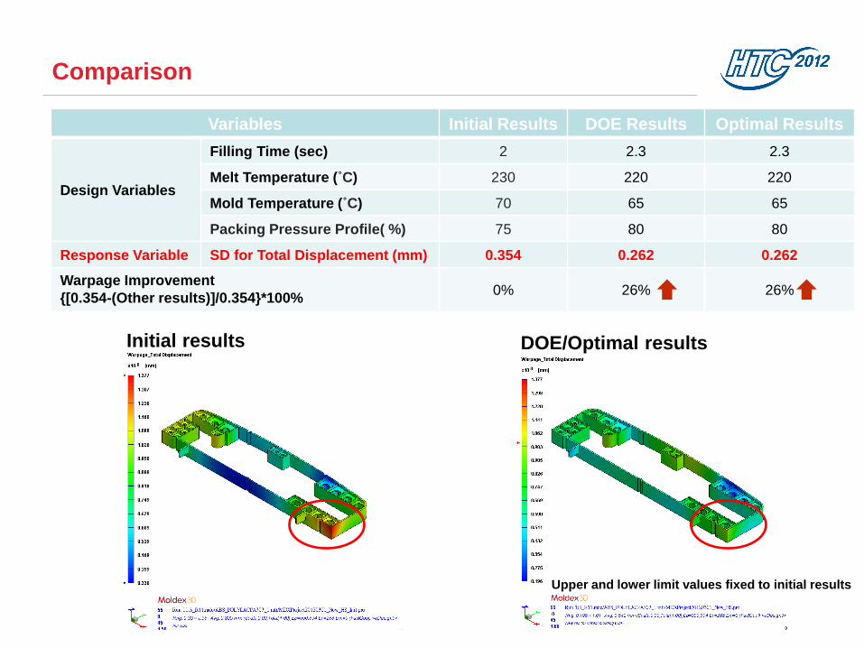
Comparison
Variables Initial Results DOE Results Optimal Results
Design Variables
Filling Time (sec) 2 2.3 2.3
Melt Temperature (˚C) 230 220 220
Mold Temperature (˚C) 70 65 65
Packing Pressure Profile( %) 75 80 80
Response Variable SD for Total Displacement (mm) 0.354 0.262 0.262
Warpage Improvement
{[0.354-(Other results)]/0.354}*100% 0% 26% 26%
Initial results DOE/Optimal results
Upper and lower limit values fixed to initial results

Conclusion
• The integration between Moldex3D and HyperStudy helps users to find out the
optimal process conditions for injection molding systemically.
• Both DOE Study and Optimal Study can reduce maximum displacement from 1.4
mm (initial design) to 1.0 mm (optimal design), which is a 27% improvement.
• According to the DOE Study results, melt temperature is the most important and
filling time is the least important factor for warpage of this case.
• Both DOE Study and Optimization Study can reduce warpage by 26%. However,
please note it’s likely to find different optimization studies lead to slightly
different optimized results.