Embed Size (px)
Citation preview
Moisture Controlin
Museums
Presented by
Boggarm S. Setty, P.E.Setty & Associates, Ltd.
ASHRAE Winter Meeting, New York, January 2008
Moisture Control in Museums
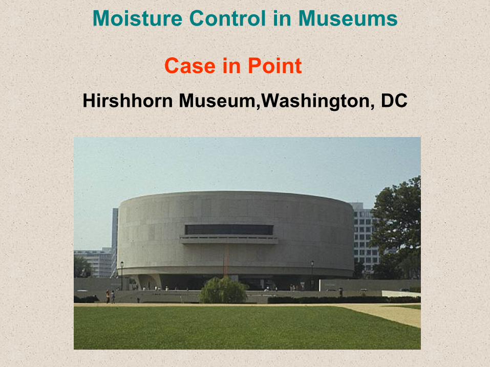
Hirshhorn Museum,Washington, DC
Case in Point
Moisture Control in Museums
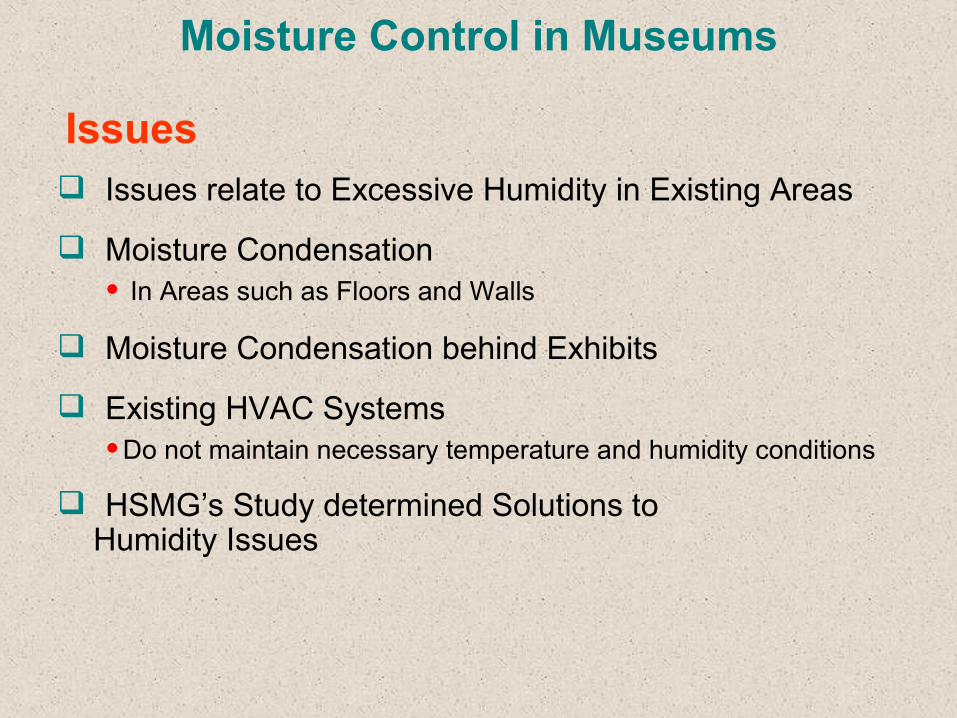
Issues relate to Excessive Humidity in Existing Areas
Moisture Condensation• In Areas such as Floors and Walls
Moisture Condensation behind Exhibits
Existing HVAC Systems •Do not maintain necessary temperature and humidity conditions
HSMG’s Study determined Solutions to Humidity Issues
Issues
Moisture Control in Museums
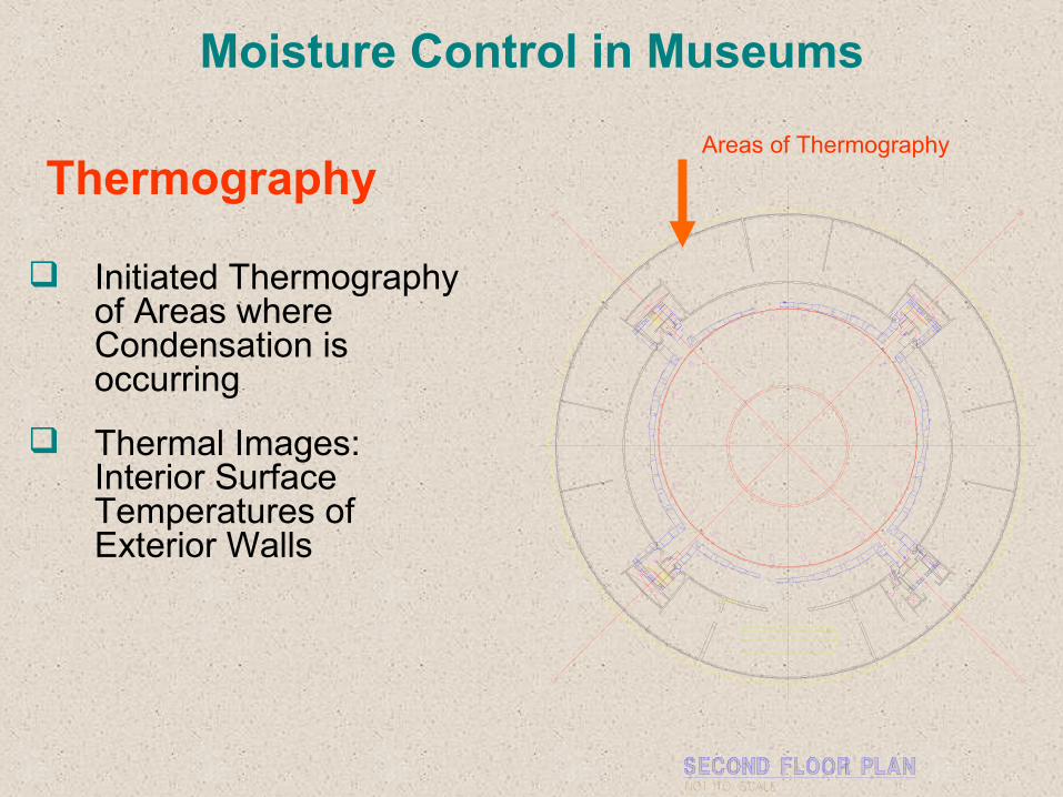
Initiated Thermography of Areas where Condensation is occurring
Thermal Images: Interior Surface Temperatures of Exterior Walls
ThermographyAreas of Thermography
Moisture Control in Museums
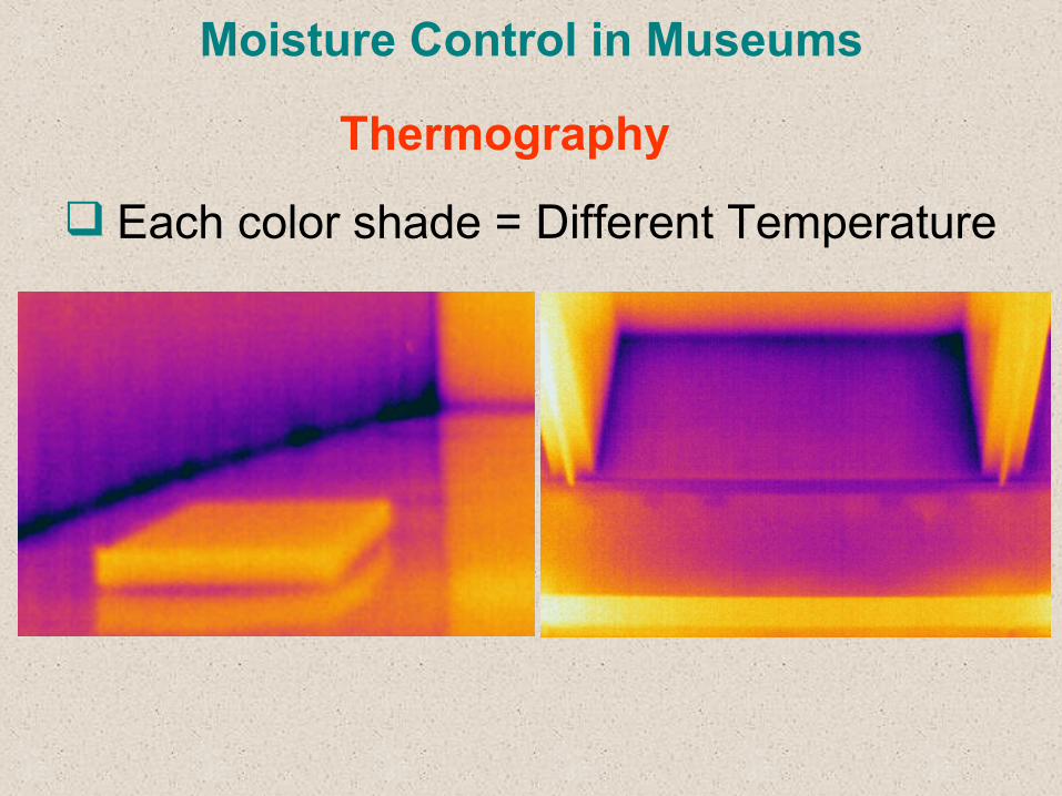
Each color shade = Different Temperature
Thermography
Moisture Control in Museums
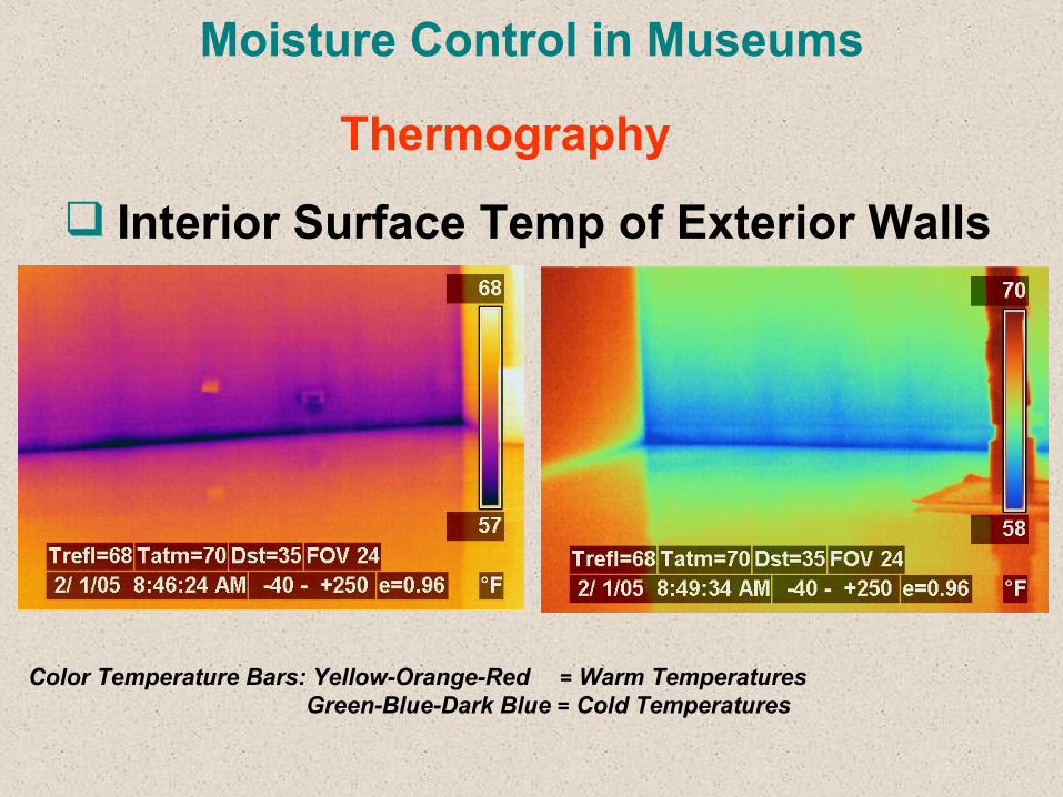
Interior Surface Temp of Exterior Walls
Color Temperature Bars: Yellow-Orange-Red = Warm Temperatures Green-Blue-Dark Blue = Cold Temperatures
Thermography
Moisture Control in Museums
Determine Existing Envelope Conditions to prevent condensation with insulation options.
Monitor Exterior Wall Dewpoint and Temperature Profiles during winter months.
Determine Building Pressure Characteristics when system is in operation.
Determine HVAC Control System operation.
Recommend proper Envelope Modification, HVAC Improvements and Recommissioning to Prevent Condensation.
Study Issues

Round Envelope: 24-inch thick concrete No Insulation Exterior: Rough Finished Interior Drywall or Plaster Finish Concrete Structure:
Moisture Control in Museums
Envelope Characteristics
VINYL BASE,
FINISH FLOORBASE
SECURE TO CONCRETECONT. METAL RUNNER
DECK ABOVE
20 GA @ 16" O.C.
BD. @ EACH SIDE1 LAYER OF 5/8" GYP.
3 5/8" METAL STUDSPLAN
TOP
CEILING
SEE SCHEDULE
Moisture Control in Museums
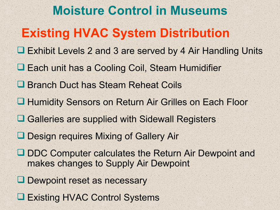
Exhibit Levels 2 and 3 are served by 4 Air Handling Units
Each unit has a Cooling Coil, Steam Humidifier
Branch Duct has Steam Reheat Coils
Humidity Sensors on Return Air Grilles on Each Floor
Galleries are supplied with Sidewall Registers
Design requires Mixing of Gallery Air
DDC Computer calculates the Return Air Dewpoint and makes changes to Supply Air Dewpoint
Dewpoint reset as necessary
Existing HVAC Control Systems
Existing HVAC System Distribution
Moisture Control in Museums
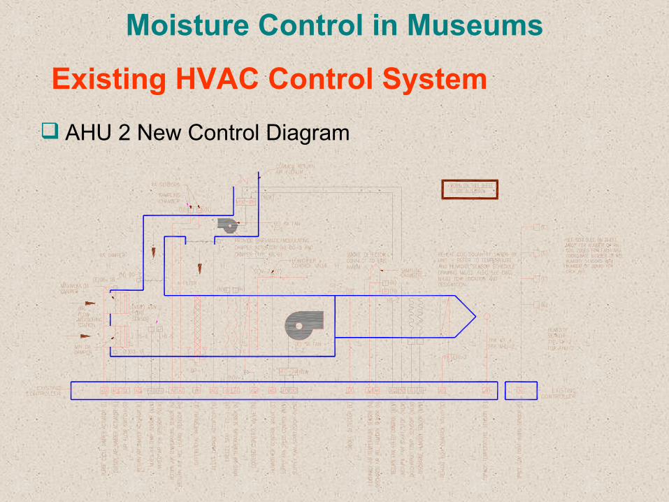
AHU 2 New Control Diagram
Existing HVAC Control System
Moisture Control in Museums
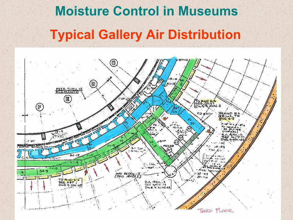
Typical Gallery Air Distribution
Moisture Control in Museums
Building has High Humidity Levels with occasional Condensation on Cold Walls
More Condensation behind Exhibits
More Condensation on Second Floor
Possible Pressure pushing High Humidity Air, which will condense in the Walls
Evaluation of Existing Conditions
Moisture Control in Museums
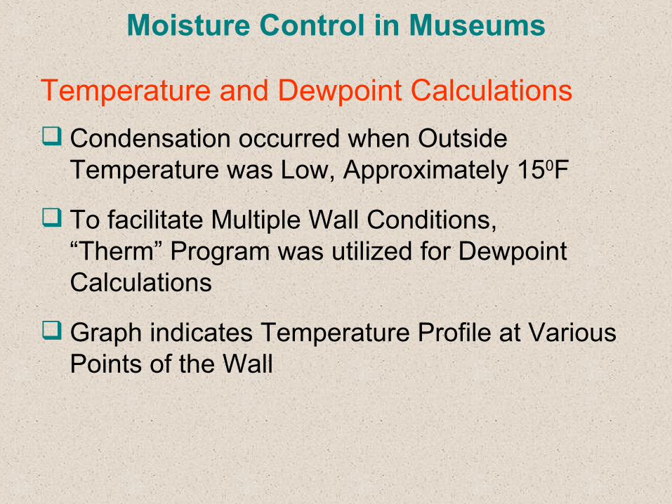
Condensation occurred when Outside Temperature was Low, Approximately 150F
To facilitate Multiple Wall Conditions, “Therm” Program was utilized for Dewpoint Calculations
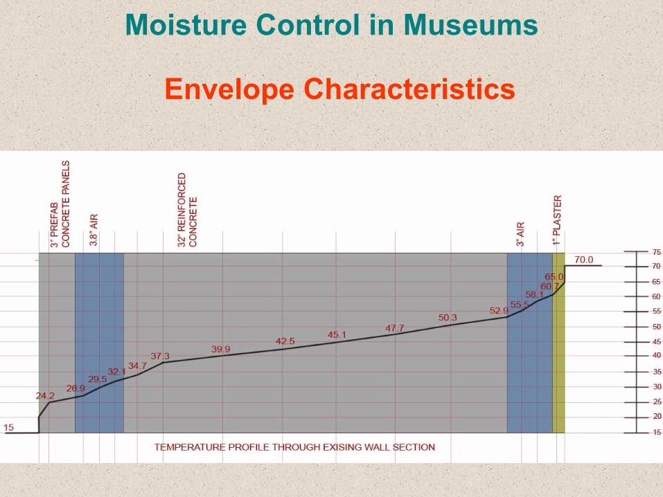
Graph indicates Temperature Profile at Various Points of the Wall
Temperature and Dewpoint Calculations
Moisture Control in Museums
Envelope Characteristics
Moisture Control in Museums
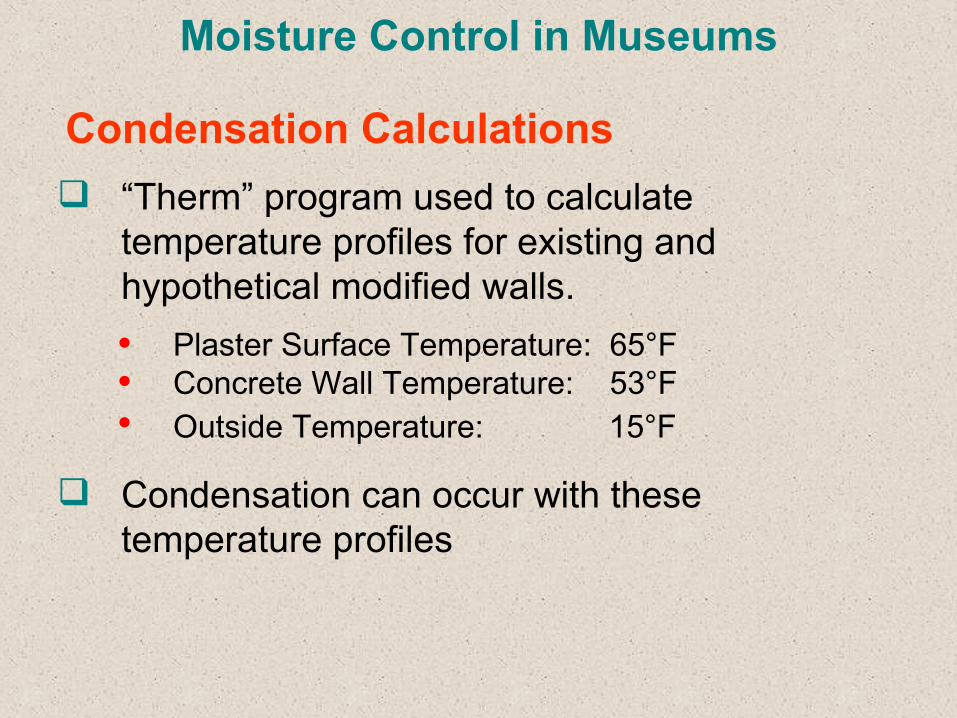
“Therm” program used to calculate temperature profiles for existing and hypothetical modified walls.• Plaster Surface Temperature: 65°F• Concrete Wall Temperature: 53°F• Outside Temperature: 15°F
Condensation can occur with these temperature profiles
Condensation Calculations
Moisture Control in Museums
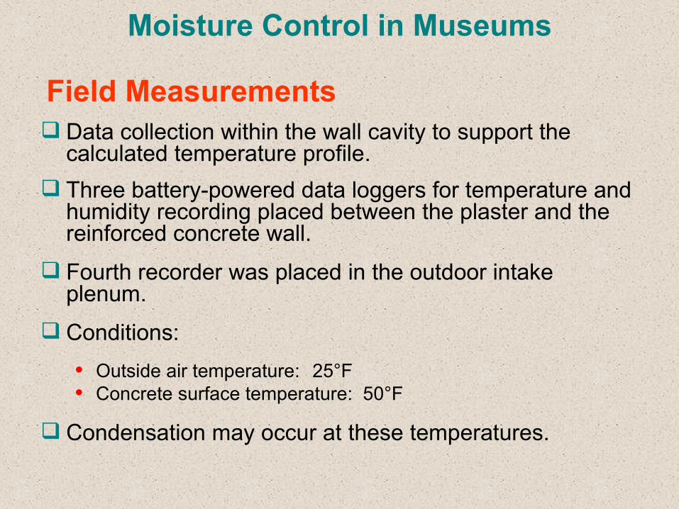
Data collection within the wall cavity to support the calculated temperature profile.
Three battery-powered data loggers for temperature and humidity recording placed between the plaster and the reinforced concrete wall.
Fourth recorder was placed in the outdoor intake plenum.
Conditions:
• Outside air temperature: 25°F• Concrete surface temperature: 50°F
Condensation may occur at these temperatures.
Field Measurements
Moisture Control in Museums
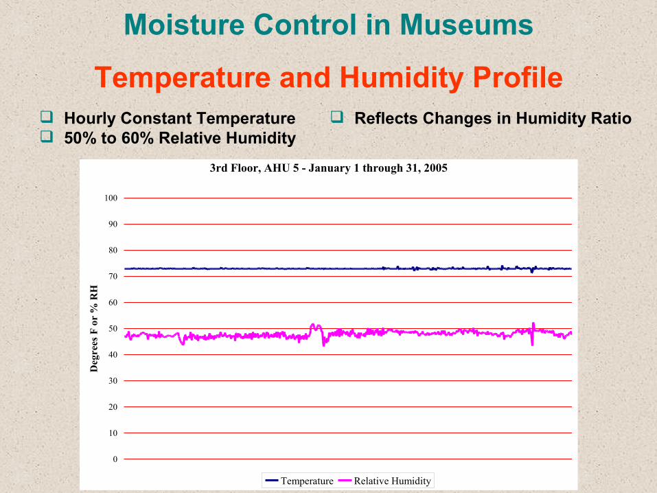
Hourly Constant Temperature 50% to 60% Relative Humidity
Temperature and Humidity Profile
3rd Floor, AHU 5 - January 1 through 31, 2005
0
10
20
30
40
50
60
70
80
90
100
Deg
rees
F o
r %
RH
Temperature Relative Humidity
Reflects Changes in Humidity Ratio
Moisture Control in Museums
Instruments used:
• Infrared Mini-thermostat• Electronic Digitized Temp/Humidity Instrument
Measurements Conducted for AHU# 5, 6 and 7 Temperature Measurements Nearly Constant Temperature 50% to 60% Relative Humidity Fluctuations in Relative Humidity Observed for
all AHU’s
Temperature Measurements
Moisture Control in Museums
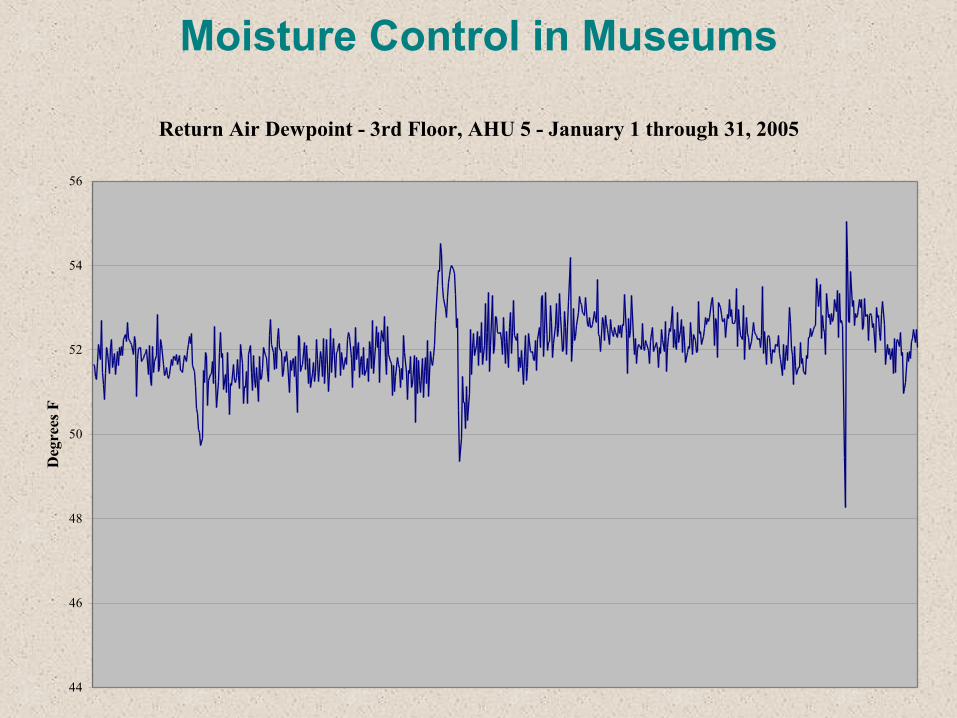
Return Air Dewpoint - 3rd Floor, AHU 5 - January 1 through 31, 2005
44
46
48
50
52
54
56
Deg
rees
F
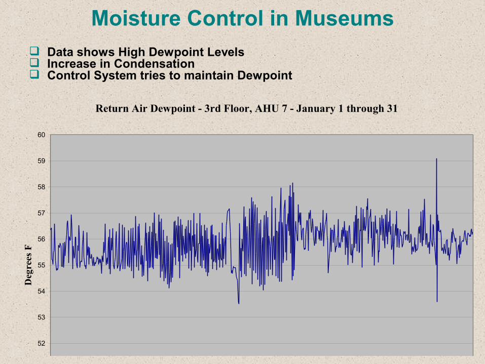
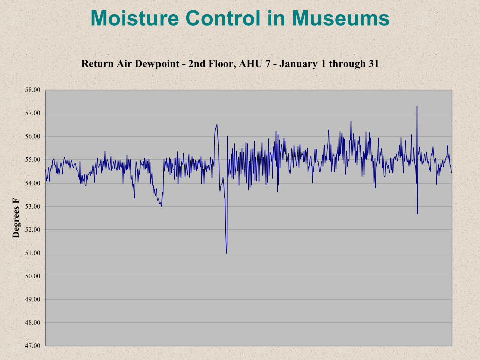
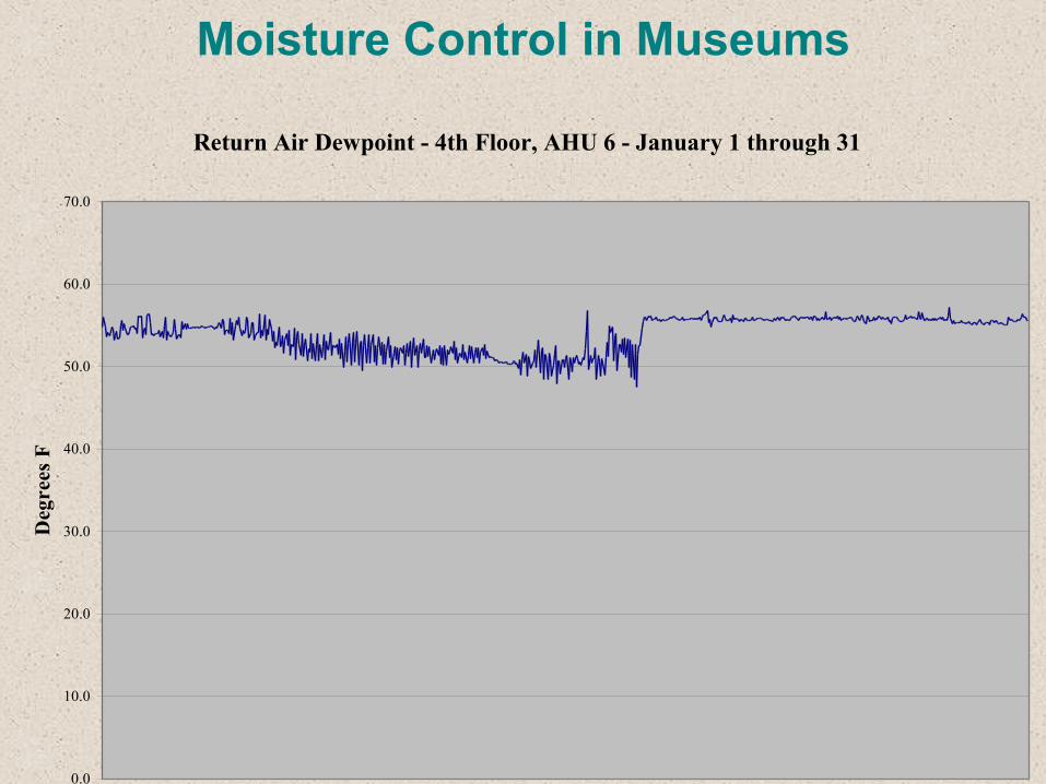
Moisture Control in Museums Data shows High Dewpoint Levels Increase in Condensation Control System tries to maintain Dewpoint
Return Air Dewpoint - 3rd Floor, AHU 7 - January 1 through 31
50
51
52
53
54
55
56
57
58
59
60
Deg
rees
F
Moisture Control in Museums
Return Air Dewpoint - 2nd Floor, AHU 7 - January 1 through 31
47.00
48.00
49.00
50.00
51.00
52.00
53.00
54.00
55.00
56.00
57.00
58.00
Deg
rees
F
Moisture Control in Museums
»
Return Air Dewpoint - 4th Floor, AHU 6 - January 1 through 31
0.0
10.0
20.0
30.0
40.0
50.0
60.0
70.0
Deg
rees
F
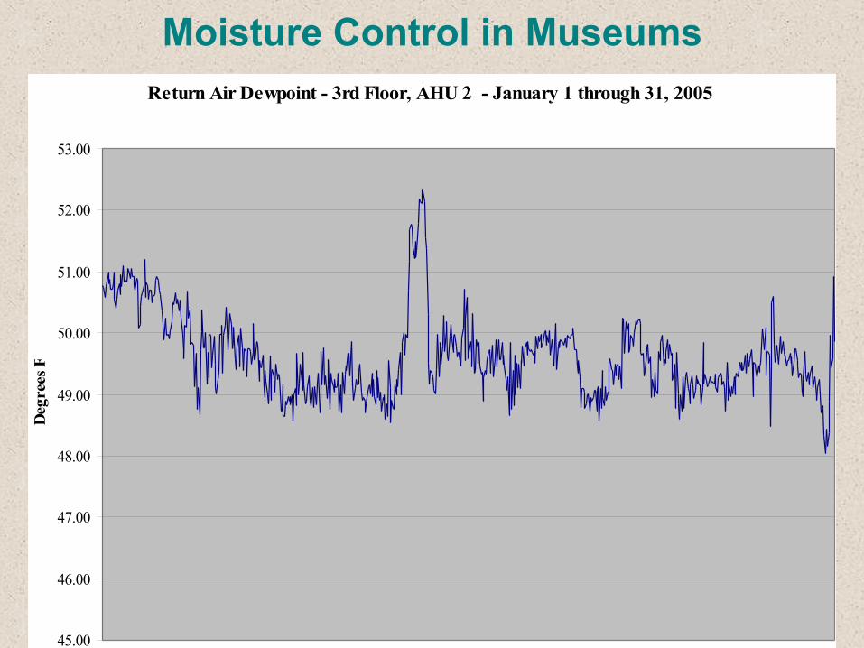
Moisture Control in MuseumsReturn Air Dewpoint - 3rd Floor, AHU 2 - January 1 through 31, 2005
45.00
46.00
47.00
48.00
49.00
50.00
51.00
52.00
53.00
Deg
rees
F
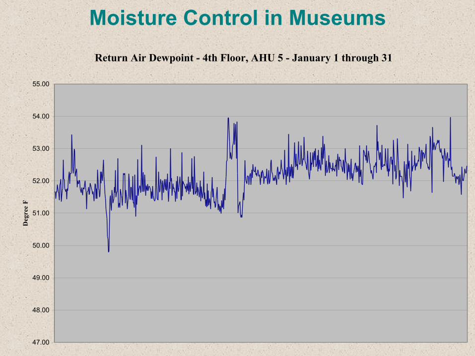
Moisture Control in MuseumsReturn Air Dewpoint - 4th Floor, AHU 5 - January 1 through 31
47.00
48.00
49.00
50.00
51.00
52.00
53.00
54.00
55.00
Deg
ree
F
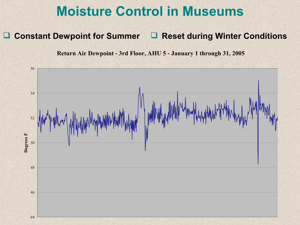
Moisture Control in Museums Reset during Winter Conditions
Return Air Dewpoint - 3rd Floor, AHU 5 - January 1 through 31, 2005
44
46
48
50
52
54
56
Deg
rees
F
Constant Dewpoint for Summer
Moisture Control in Museums
Over-pressurization pushes Air into the Wall, causing Condensation
Maintaining Positive Pressure at Building Wall does not guarantee Condensation Prevention
Normal Practice Recommended to Maintain Slight Positive Pressure, approximately 2 Pascal
Neutral Pressure prevents Exfiltration of Air during low Outside Air Temperatures
Pressurization
Moisture Control in Museums
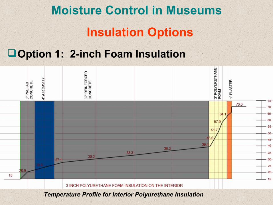
Option 1: 2-inch Foam Insulation
Insulation Options
Temperature Profile for Interior Polyurethane Insulation
Moisture Control in Museums
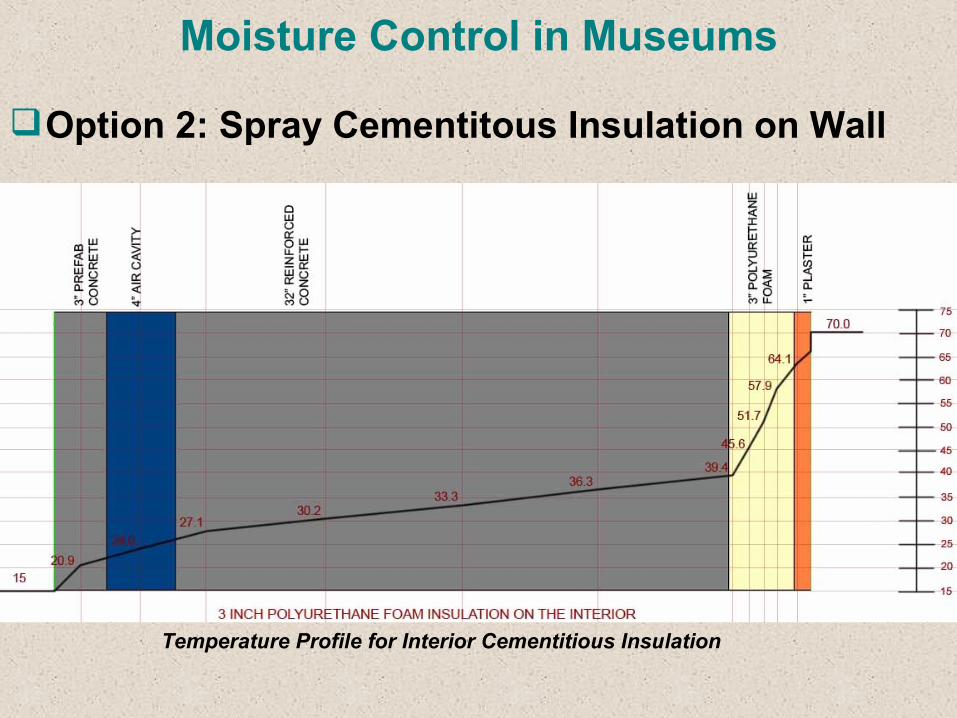
Option 2: Spray Cementitous Insulation on Wall
Temperature Profile for Interior Cementitious Insulation
Moisture Control in Museums
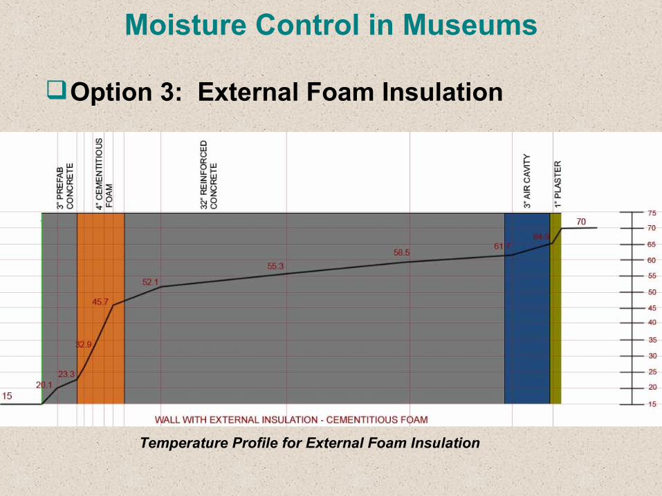
Option 3: External Foam Insulation
Temperature Profile for External Foam Insulation
Moisture Control in Museums
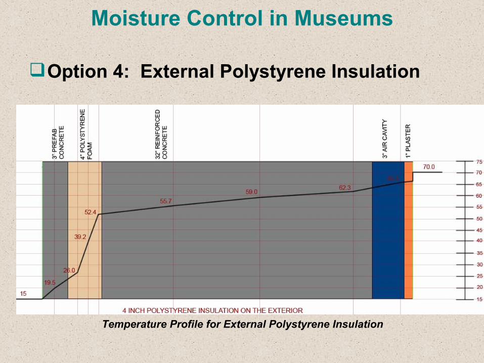
Option 4: External Polystyrene Insulation
Temperature Profile for External Polystyrene Insulation
Moisture Control in Museums
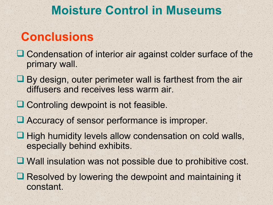
Condensation of interior air against colder surface of the primary wall.
By design, outer perimeter wall is farthest from the air diffusers and receives less warm air.
Controling dewpoint is not feasible. Accuracy of sensor performance is improper. High humidity levels allow condensation on cold walls,
especially behind exhibits. Wall insulation was not possible due to prohibitive cost. Resolved by lowering the dewpoint and maintaining it
constant.
Conclusions
Moisture Control in Museums
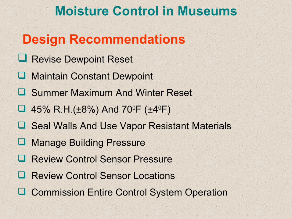
Revise Dewpoint Reset
Maintain Constant Dewpoint Summer Maximum And Winter Reset 45% R.H.(±8%) And 700F (±40F) Seal Walls And Use Vapor Resistant Materials Manage Building Pressure Review Control Sensor Pressure Review Control Sensor Locations Commission Entire Control System Operation
Design Recommendations
Moisture Control in Museums
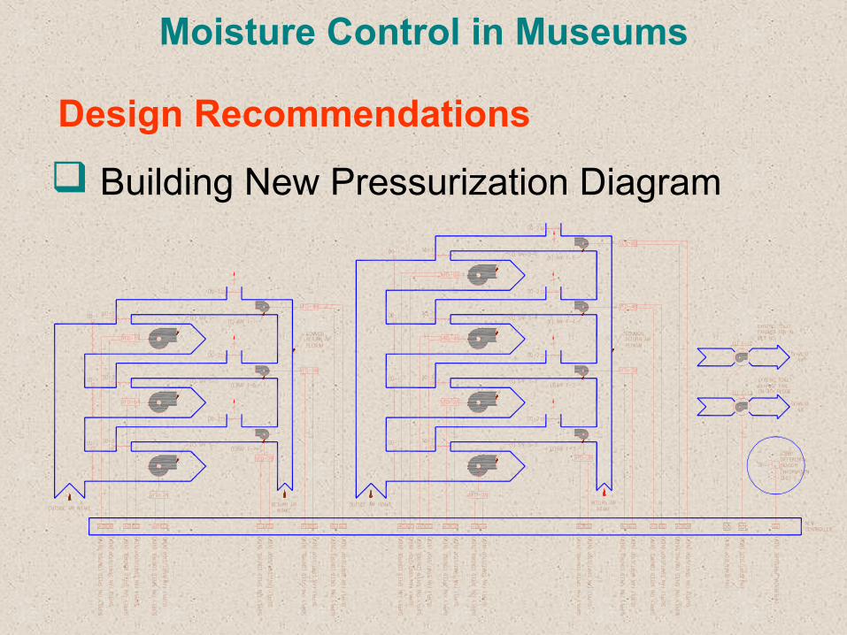
Building New Pressurization Diagram
Design Recommendations
Moisture Control in Museums
Maintain Slightly Positive Pressure -- 2 Pascals
Variable Frequency Drives on all AHU’s and Return Air Fans
Run AHU’s at half-speed during unoccupied hours
Connect all the Existing Fans to the DDC System
Constant Dewpoint Temperature during Summer and Reset during Winter
Commissioning / Building Pressure Control
Moisture Control in Museums
Questions and Answers