Embed Size (px)
Citation preview
20
Cognitive Radio: UWB Integration and Related Antenna Design
Mohammed Al-Husseini1, Karim Y. Kabalan1, Ali El-Hajj1 and Christos G. Christodoulou2
1American University of Beirut 2University of New Mexico
1Lebanon 2USA
1. Introduction
The emerging feature-rich and high-data-rate wireless applications have put increasing demand on radio spectrum. The scarcity of spectrum and the inefficiency in its usage, as caused by the current radio spectrum regulations, necessitate the development of new dynamic spectrum allocation policies to better exploit the existing spectrum. The current spectrum allocation regulations assign specific bands to particular services, and grant licensed band access to licensed users only. Cognitive Radio (CR) will revolutionize the way spectrum is allocated. In a CR network, the intelligent radio part allows unlicensed users (secondary users) to access spectrum bands licensed to primary users, while avoiding interference with them. In this scheme, a secondary user can use spectrum sensing hardware/software to locate spectrum portions with reduced primary user activity or idle spectrum slots, select the best available channel, coordinate access to this channel with other secondary users, and vacate the channel when a primary user needs it. To achieve this, the transceiver in a CR system should have awareness of the radio environment in terms of spectrum usage, power spectral density of transmitted/received signals, and wireless protocol signaling, should be able to adaptively tune system parameters such as transmit power, carrier frequency, and modulation strategy. The transceiver should also be ended with an antenna system that can simultaneously operate over a wide frequency band (sensing) and a chosen narrow band (communication), or operate over an ultra-wide frequency band while possibly blocking signals in a narrow frequency range. Ultra-wideband (UWB) is a transmission technique that uses pulses with a very short time duration across a very large frequency portion of the spectrum. UWB is different from other radio frequency communication techniques in that it does not use RF carriers, but instead employs modulated high frequency pulses of low power with a duration of less than 1 nanosecond. From the perspective of other communication systems, the UWB transmissions are part of the low power background noise. Therefore UWB promises to enable the usage of licensed spectrum without harmful interference to primary communication systems, and can be used as an enabling technology for implementing CR. In this chapter, we offer a general overview of Cognitive Radio and dynamic spectrum access, discuss the advantages of using UWB as an enabling technology for CR, and give
www.intechopen.com
New Trends in Technologies: Control, Management, Computational Intelligence and Network Systems
396
special attention to the latest research on Antenna Design for CR. The chapter will be organized as follows. Section 2 will discuss the current radio spectrum regulations and spectrum usage, and will focus on the availability of radio spectrum and the efficiency of its use. Section 3 will deal with the concepts of Spectrum Sharing and Dynamic Spectrum Access. Section 4 will investigate the advantages of integrating CR with the UWB technology and the recent research on the topic. Section 5 will review the recent work in antenna design for Cognitive Radio. Finally, a conclusion will be given in Section 6.
2. Current radio spectrum allocations/regulations
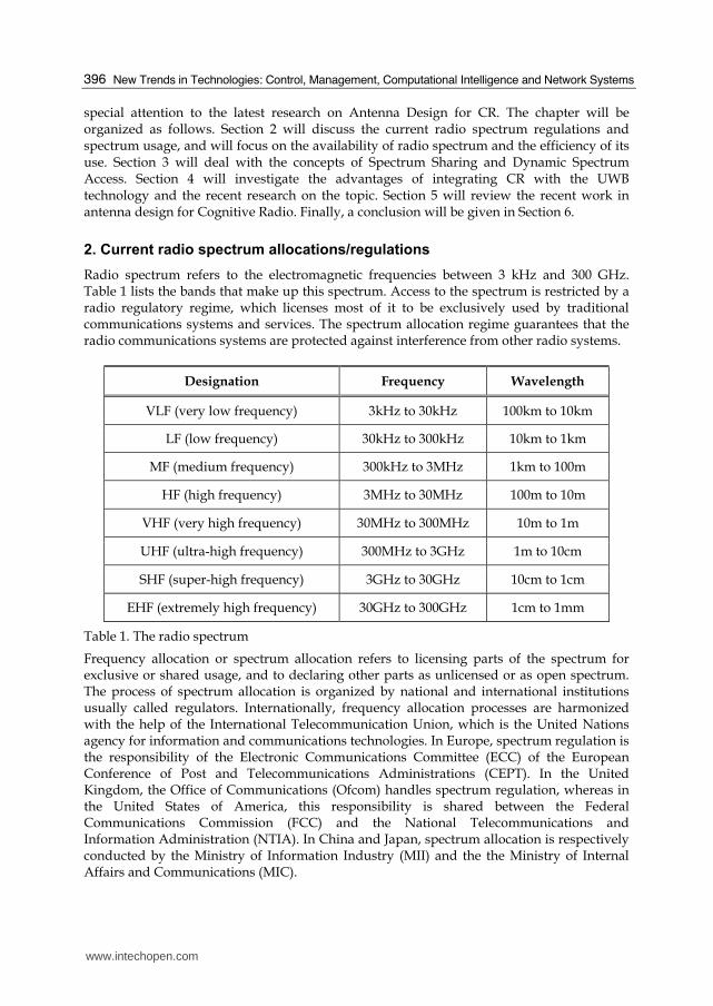
Radio spectrum refers to the electromagnetic frequencies between 3 kHz and 300 GHz. Table 1 lists the bands that make up this spectrum. Access to the spectrum is restricted by a radio regulatory regime, which licenses most of it to be exclusively used by traditional communications systems and services. The spectrum allocation regime guarantees that the radio communications systems are protected against interference from other radio systems.
Designation Frequency Wavelength
VLF (very low frequency) 3kHz to 30kHz 100km to 10km
LF (low frequency) 30kHz to 300kHz 10km to 1km
MF (medium frequency) 300kHz to 3MHz 1km to 100m
HF (high frequency) 3MHz to 30MHz 100m to 10m
VHF (very high frequency) 30MHz to 300MHz 10m to 1m
UHF (ultra-high frequency) 300MHz to 3GHz 1m to 10cm
SHF (super-high frequency) 3GHz to 30GHz 10cm to 1cm
EHF (extremely high frequency) 30GHz to 300GHz 1cm to 1mm
Table 1. The radio spectrum
Frequency allocation or spectrum allocation refers to licensing parts of the spectrum for exclusive or shared usage, and to declaring other parts as unlicensed or as open spectrum. The process of spectrum allocation is organized by national and international institutions usually called regulators. Internationally, frequency allocation processes are harmonized with the help of the International Telecommunication Union, which is the United Nations agency for information and communications technologies. In Europe, spectrum regulation is the responsibility of the Electronic Communications Committee (ECC) of the European Conference of Post and Telecommunications Administrations (CEPT). In the United Kingdom, the Office of Communications (Ofcom) handles spectrum regulation, whereas in the United States of America, this responsibility is shared between the Federal Communications Commission (FCC) and the National Telecommunications and Information Administration (NTIA). In China and Japan, spectrum allocation is respectively conducted by the Ministry of Information Industry (MII) and the the Ministry of Internal Affairs and Communications (MIC).
www.intechopen.com
Cognitive Radio: UWB Integration and Related Antenna Design
397
Four approaches can differentiate the regulation of radio spectrum (Berlemann & Mangold, 2009). These are 1) the licensed spectrum for exclusive usage, 2) the licensed spectrum for shared usage, 3) the unlicensed spectrum, and 4) the open spectrum. In the first approach, which FCC calls the exclusive use model, the licensee has exclusive usage rights for a specific spectrum. An example of a spectrum licensed for exclusive usage are the frequency bands sold for use in the Universal Mobile Telecommunication System (UMTS) in Europe. The second approach (called the command-and-control model by FCC) restricts the licensed spectrum for shared usage to a specific technology. An example of this approach could be the spectrum used for public safety services. In the unlicensed spectrum approach, which FCC calls the commons model or open access, the spectrum is available to all radio systems operating according to regulated standards. The Industrial, Scientific and Medical (ISM) 2.4 GHz band and the Unlicensed National Information Infrastructure (U-NII) 5–6 GHz bands are examples of unlicensed or license-exempt spectrum. The fourth and last approach, the open spectrum, allows anyone to access any range of the spectrum without any restriction. Yet, a minimum set of rules from technical standards or etiquettes that are required for sharing spectrum should be respected in this approach. With the licensed spectrum approaches, spectrum resources could often be wasted. For example, portions of the spectrum could become unused because the communications systems licensed to operate in this spectrum have become more spectrum efficient due to technology advancements, and thus these communications systems can operate in only a percentage of the spectrum initially licensed for that specific service. In another direction, if a service to which spectrum is licensed is not economically successful, its licensed spectrum remains largely unused. Furthermore, the spectrum dedicated to public safety and military radio systems is only occasionally used, which means it is unused most of the times. As a result, large parts of the spectrum are currently used inefficiently. Paradoxically, 90 to 95% of the licensed radio spectrum is not in use at any location at any given time (Berlemann & Mangold, 2009), especially that the current radio regulatory regime is too complex to handle the increasingly dynamic nature of emerging wireless applications. Added to the fact that the demand for additional spectrum is growing fast, even faster than costly technologies like Multiple Input Multiple Output (MIMO) and Space Division Multiple Access (SDMA) can improve spectrum efficiency, the conclusion is that the current spectrum regulations should be fundamentally rethought in order to solve the spectrum scarcity and limited radio resources problems. Could the solution be in more unlicensed spectrum? There is definitely a strong motivation for more unlicensed spectrum, due to its commercial success and the many different radio communications systems that operate within such spectrum. However, as more parties and technologies utilize unlicensed spectrum, it is becoming more crowded and consequently less available to all. This again necessitates the availability of more spectrum, or more efficient radio systems.
3. Dynamic spectrum access and cognitive radio
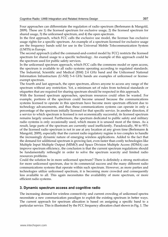
The increasing demand for wireless connectivity and current crowding of unlicensed spectra necessitate a new communication paradigm to exploit the existing spectrum in better ways. The current approach for spectrum allocation is based on assigning a specific band to a particular service. This is illustrated by the FCC frequency allocation chart shown in Fig. 1. The
www.intechopen.com
New Trends in Technologies: Control, Managem
ent, Computational Intelligence and Network System
s
398
spectru
m
chart
con
tains
ov
erlapp
ing
allo
cation
s in
m
ost
frequ
ency
b
and
s an
d
seems
to
ind
icate a hig
h d
egree o
f spectru
m u
tilization
. Ho
wev
er, wh
ile the sp
ectral efficiency
of so
me
radio
system
s is con
tinu
ally im
pro
vin
g, th
ey are faced
with
increasin
g in
terference th
at limits
netw
ork
capacity
and
scalability
. Th
e FC
C S
pectru
m P
olicy
Task
Fo
rce (FC
C, 2002) rep
orted
v
ast temp
oral an
d g
eog
raph
ic variatio
ns in
the u
sage o
f allocated
spectru
m w
ith u
tilization
ran
gin
g fro
m 15 to
85% in
the b
and
s belo
w 3 G
Hz. In
the freq
uen
cy ran
ge ab
ov
e 3 GH
z the
ban
ds are ev
en m
ore p
oo
rly u
tilized. In
oth
er wo
rds, a larg
e po
rtion
of th
e assign
ed sp
ectrum
is u
sed sp
orad
ically, lead
ing
to an
un
der u
tilization
of a sig
nifican
t amo
un
t of sp
ectrum
. Th
is in
efficiency
arises from
the in
flexibility
of th
e regu
latory
and
licensin
g p
rocess, w
hich
typ
ically
assign
s the co
mp
lete righ
ts to a freq
uen
cy b
and
to a p
rimary
user. T
his ap
pro
ach m
akes it
extremely
difficu
lt to recy
cle these b
and
s on
ce they
are allocated
, even
if these u
sers po
orly
u
tilize this v
aluab
le resou
rce. A so
lutio
n to
this in
efficiency
, wh
ich h
as been
hig
hly
successfu
l
in th
e ISM
(2.4 GH
z), the U
-NII (5−
6 GH
z), and
micro
wav
e (57−64 G
Hz) b
and
s, is to m
ake
spectra av
ailable o
n an
un
licensed
basis. H
ow
ever, in
ord
er to o
btain
spectra fo
r un
licensed
o
peratio
n, n
ew sh
aring
con
cepts h
ave b
een in
trod
uced
to allo
w u
se by
secon
dary
users u
nd
er th
e requ
iremen
t that th
ey lim
it their in
terference to
pre-existin
g p
rimary
users.
U.S. D
EPARTMENTOFCOMME
RCE
NATIONALTELEC
OMM
UNICATIO
NS&
INFORMA
TIONADM IN ISTRATIO
N
MOBILE (AERONAUTICAL TELEMETERING)
S)
5.685.735.90
5.95
6.2
6.525
6.6856.765
7.0
7.1
7.37.35
8.18.195
8.815
8.9659.040
9.4
9.5
9.9
9.99510.00310.00510.110.15
11.175
11.27511.411.611.65
12.05
12.10
12.23
13.2
13.26
13.3613.4113.5713.6
13.813.8714.014.2514.35
14.990
15.00515.01015.10
15.615.8
16.36
17.41
17.4817.55
17.917.9718.0318.06818.16818.7818.919.02
19.6819.8019.99019.99520.00520.010
21.0
21.45
21.8521.92422.0
22.85523.023.223.35
24.8924.9925.005
25.0125.0725.2125.3325.5525.6726.126.17526.4826.9526.9627.2327.4127.5428.0
29.729.829.8929.9130.0
UN
ITE
D
STA
TE
S
TH
E R
AD
IO S
PE
CT
RU
M
NON-G
OVERNM
ENT EXCLUSIVE
GO
VERNMENT/NO
N-GO
VERNMENT SHARED
GO
VERNMENT EXCLUSIVE
RA
DIO
SE
RV
ICE
S C
OLO
R LE
GE
ND
AC
TIV
ITY
CO
DE
NO
T A
LLOC
AT
ED
RA
DIO
NA
VIG
AT
ION
FIX
ED
MA
RIT
IME
MO
BILE
FIX
ED
MA
RIT
IME
MO
BILE
FIX
ED
MA
RIT
IME
MO
BILE
Radiolocation
RAD
ION
AVIGATIO
N
FIX
ED
MA
RIT
IME
MO
BILE
Radiolocation
FIX
ED
MA
RIT
IME
MO
BILE
FIX
ED
MA
RIT
IME
MO
BILE
AE
RO
NA
UT
ICA
LR
AD
ION
AV
IGA
TIO
N
AERONAUTICALRADIONAVIGATION
AeronauticalMobile
MaritimeRadionavigation(Radio Beacons)
MARITIMERADIONAVIGATION(RADIO BEACONS)
AeronauticalRadionavigation(Radio Beacons)
3
9
14
19.95
20.05
30
30
59
61
70
90
110
130
160
190
200
275
285
300
3 k
Hz
300 k
Hz
300 k
Hz
3 M
Hz
3 M
Hz
30 M
Hz
30 M
Hz
300 M
Hz
3 G
Hz
300 G
Hz
300 M
Hz
3 G
Hz
30 G
Hz
AeronauticalR
adionavigation(R
adio Beacons)
MAR
ITIME
RAD
ION
AVIGATIO
N(R
ADIO
BEACO
NS)
AeronauticalMobile
MaritimeRadionavigation(Radio Beacons)
AERONAUTICALRADIONAVIGATION(RADIO BEACONS)
AERO
NAU
TICAL
RAD
ION
AVIGATIO
N(R
ADIO
BEACO
NS)
AeronauticalM
obile
Aeronautical Mobile RADIONAVIGATION
AERONAUTICALRADIONAVIGATION
MARITIMEMOBILE
Aeronautical
Radionavigation
MOBILE (DISTRESS AND CALLING)
MARITIME MOBILE
MARITIMEMOBILE
(SHIPS ONLY)
MOBILE
AERONAUTICALRADIONAVIGATION(RADIO BEACONS)
AERONAUTICALRADIONAVIGATION(RADIO BEACONS)
BRO
ADC
ASTING
(AM R
ADIO
)
MARITIME MOBILE (TELEPHONY)
MARITIME MOBILE (TELEPHONY) MOBILE (DISTRESS AND CALLING)
MAR
ITIME
MO
BILE
LAND
MO
BILE
MO
BILE
FIXE
D
STANDARD FREQ. AND TIME SIGNAL (2500kHz)
STANDARD FREQ. AND TIME SIGNAL
Space Research
MAR
ITIME
MO
BILE
LAND
MO
BILE
MO
BILE
FIXE
D
AERONAUTICALMOBILE (R)
STANDARD FREQ.
AERONAUTICAL MOBILE (R)
AERONAUTICALMOBILE (OR)
AERONAUTICALMOBILE (R)
FIXED
MO
BILE**
Radio-
location
FIXEDMOBILE*
AMATEU
R
FIXED
FIXED
FIXED
FIXED
FIXED
MAR
ITIME
MO
BILE
MOBILE*
MOBILE*
MOBILE
STANDARD FREQ. AND TIME SIGNAL (5000 KHZ)
AERONAUTICAL MOBILE (R)
AERONAUTICAL MOBILE (OR)
STANDARD FREQ. Space Research
MO
BILE**
AERONAUTICAL MOBILE (R)
AERONAUTICAL MOBILE (OR)
FIXEDMOBILE*
BROADCASTING
MARITIME MOBILE
AERONAUTICAL MOBILE (R)
AERONAUTICAL MOBILE (OR)
FIXEDMobile
AMATEUR SATELLITEAMATEUR
AMATEUR
FIX
ED
Mobile
MARITIME MOBILE
MAR
ITIME
MO
BILE
AERONAUTICAL MOBILE (R)AERONAUTICAL MOBILE (OR)
FIXED
BROADCASTING
FIXED
STANDARD FREQ. AND TIME SIGNAL (10,000 kHz)
STANDARD FREQ. Space ResearchAERONAUTICAL MOBILE (R)
AMATEUR
FIXED
Mobile*
AERONAUTICAL MOBILE (R)AERONAUTICAL MOBILE (OR)
FIXED
FIXED
BROADCASTING
MARITIMEMOBILE
AERONAUTICAL MOBILE (R)
AERONAUTICAL MOBILE (OR)
RADIO ASTRONOMY
Mobile*
AMATEUR
BROADCASTING
AMATEUR AMATEUR SATELLITE
Mobile*FIXED
BROADCASTING
STANDARD FREQ. AND TIME SIGNAL (15,000 kHz)
STANDARD FREQ. Space Research
FIX
ED
AERONAUTICAL MOBILE (OR)
MARITIMEMOBILE
AERONAUTICAL MOBILE (OR)AERONAUTICAL MOBILE (R)
FIXED
FIXED
BROADCASTING
STANDARD FREQ. Space Research
FIXED
MARITIME MOBILE
MobileFIXED
AMATEUR AMATEUR SATELLITE
BROADCASTINGFIXED
AERONAUTICAL MOBILE (R)
MARITIME MOBILE
FIXEDFIXED
FIXED
Mobile*
MOBILE**
FIXED
STANDARD FREQ. AND TIME SIGNAL (25,000 kHz)
STANDARD FREQ. Space Research
LAND MOBILEMARITIME MOBILE
LAND MOBILE MOBILE**
RADIO ASTRONOMYBROADCASTING
MARITIME MOBILE LAND MOBILE
FIXED MOBILE**FIXED
MOBILE**
MOBILE
FIXED
FIXED
FIXEDFIXED
FIXED
LAND MOBILE
MOBILE**
AMATEUR AMATEUR SATELLITE
MOBILE
LAND MOBILE
MOBILE
MOBILE
FIXED
FIXED
MOBILE
MOBILE
FIXED
FIXED
LANDMOBILE
LANDMOBILE
LANDMOBILE
LAND MOBILERadio Astronomy
RADIO ASTRONOMY
LAND MOBILE
FIXEDFIXED
MOBILEMOBILE
MO
BILE
LAND MOBILE
FIXED
LANDMOBILE
FIXED
FIXED
MOBILE
MOBILE
LAND
MO
BILEAM
ATEUR
BRO
ADC
ASTING
(TV CH
ANN
ELS 2-4)
FIXED MOBILE
FIXED MOBILE
FIXED MOBILEFIXED MOBILE
AERONAUTICAL RADIONAVIGATION
BRO
ADC
ASTING
(TV CH
ANN
ELS 5-6)BR
OAD
CASTIN
G(FM
RAD
IO)
AERO
NAU
TICAL
RAD
ION
AVIGATIO
N
AERONAUTICALMOBILE (R)
AERONAUTICAL MOBILEAERONAUTICAL MOBILE
AERONAUTICALMOBILE (R)
AERONAUTICALMOBILE (R)
AERONAUTICAL MOBILE (R)
MOBILEFIXED
AMATEUR
BRO
ADC
ASTING
(TV CH
ANN
ELS 7-13)
MO
BILE
FIXED
MO
BILE
FIXED
MO
BILE SATELLITE
FIXED
MO
BILESATELLITE
MO
BILE
FIXED
MO
BILESATELLITE
MO
BILE
FIXED MOBILE
AERONAUTICAL RADIONAVIGATION
STD. FREQ. & TIME SIGNAL SAT. (400.1 MHz)MET. SAT.
(S-E)SPACE RES.
(S-E)
Earth Expl.Satellite (E-S)
MOBILE SATELLITE (E-S)
FIXED MOBILERADIOASTRONOMY
RADIOLOCATION Amateur
LAND MOBILE
Meteorological
Satellite (S-E)
LAND MOBILEBROADCASTING
(TV CHANNELS 14 - 20)
BRO
ADC
ASTING
(TV CH
ANN
ELS 21-36)TV BR
OAD
CASTIN
G
RADIO ASTRONOMY
RADIOLOCATION
FIXED
Amateur
AERO
NAU
TICAL
RAD
ION
AVIGATIO
N
MOBILE**FIXED
AERONAUTICALRADIONAVIGATION
Radiolocation
RadiolocationMARITIME
RADIONAVIGATION
MARITIMERADIONAVIGATION
Radiolocation
Radiolocation
Radiolocation
RAD
IO-
LOC
ATION
RAD
IO-
LOC
ATION
Amateur
AERONAUTICALRADIONAVIGATION
(Ground)
RADIO-LOCATION
Radio-location
AERO. RADIO-NAV.(Ground)
FIXED SAT. (S-E)
RADIO-LOCATION
Radio-location
FIXED
FIXEDSATELLITE
(S-E)
FIXED
AERONAUTICAL RADIONAVIGATION
MOBILE
FIXED MOBILE
RADIO ASTRONOMY Space Research (Passive)
AERONAUTICAL RADIONAVIGATION
RADIO-LOCATION
Radio-location
RADIONAVIGATION
Radiolocation
RADIOLOCATION Radiolocation
Radiolocation
Radiolocation
RADIOLOCATIONRADIO-
LOCATION
MARITIMERADIONAVIGATION
MARITIMERADIONAVIGATION
METEOROLOGICALAIDS
Amateur
Amateur
FIXED
FIXEDSATELLITE (E-S) MOBILE
FIXEDSATELLITE (E-S)
FIXEDSATELLITE (E-S)
MOBILE
FIXED
FIXED
FIXED
FIXED
MOBILE
FIXED SPACE RESEARCH (E-S)
FIXED
FixedMOBILESATELLITE (S-E)
FIXED SATELLITE (S-E)
FIXED SATELLITE (S-E)
FIXEDSATELLITE (S-E)
FIXEDSATELLITE (S-E)
FIXEDSATELLITE (E-S)
FIXEDSATELLITE (E-S)
FIXEDSATELLITE
(E-S)FIXED
SATELLITE(E-S)
FIXED
FIXED
FIXED
FIXED
FIXED
FIXED
FIXED
MET.SATELLITE (S-E)
MobileSatellite (S-E)
MobileSatellite (S-E)
MobileSatellite (E-S)(no airborne)
Mobile Satellite(E-S)(no airborne)
Mobile Satellite (S-E)
MobileSatellite (E-S)
MOBILESATELLITE (E-S)
EARTH EXPL.SATELLITE(S-E)
EARTH EXPL.SAT. (S-E)
EARTH EXPL.SATELLITE (S-E)
MET.SATELLITE
(E-S)
FIXED
FIXED
SPACE RESEARCH (S-E)(deep space only)
SPACE RESEARCH (S-E)
AERONAUTICALRADIONAVIGATION
RADIOLOCATION Radiolocation
Radiolocation
Radiolocation
Radiolocation
MARITIMERADIONAVIGATION
MeteorologicalAidsRADIONAVIGATION
RADIOLOCATION Radiolocation
RADIO-LOCATION
Radiolocation
Radiolocation Amateur
Amateur AmateurSatellite
RADIOLOCATIONFIXED
FIXED
FIXED
F IXED
FIXEDSATELLITE
(S-E)
FIXEDSATELLITE
(S-E)
Mobile **
SPACE RESEARCH(Passive)
EARTH EXPL.SAT. (Passive)
RADIOASTRONOMY
SPACERESEARCH (Passive)
EARTH EXPL.SATELLITE (Passive)
RADIOASTRONOMY
BROADCASTINGSATELLITE
AERONAUTICAL RADIONAV. Space Research (E-S)
SpaceResearch
Land MobileSatellite (E-S)
Radio-location
RADIO-LOCATION
RADIONAVIGATION
F IXEDSATELLITE (E-S)
Land MobileSatellite (E-S)
Land MobileSatellite (E-S)Fixed Mobile FIXED
SAT. (E-S)
Fixed
MobileFIXED
MobileFIXED
MOBILE
Space Research
Space Research
Space Research
SPACE RESEARCH(Passive)RADIO ASTRONOMY EARTH EXPL. SAT.
(Passive)
Radiolocation
RADIOLOCATION Radiolocation
FX SAT (E-S)FIXED SATELLITE (E-S) F IXED
FIXED
F IXED MOBILE
EARTH EXPL.SAT. (Passive)
MOBILE
Earth Expl.Satellite (Active)
StandardFrequency and
Time SignalSatellite (E-S)
EarthExploration
Satellite(S-S)
MOBILEFIXED
MOBILE
F IXEDEarth
ExplorationSatellite (S-S)
F IXED MOBILE F IXEDSAT (E-S)
FIXED SATELLITE (E-S) MOBILE SATELLITE (E-S)
FIXEDSATELLITE
(E-S)
MOBILESATELLITE
(E-S)
StandardFrequency and
Time SignalSatellite (S-E)
Stand. Frequencyand Time SignalSatellite (S-E)
FIXED MOBILE
RADIOASTRONOMY
SPACERESEARCH
(Passive)
EARTHEXPLORATIONSAT. (Passive)
RADIONAVIGATION
RADIONAVIGATION INTER-SATELLITE
RADIONAVIGATION
RADIOLOCATION Radiolocation
SPACE RE..(Passive)
EARTH EXPL.SAT. (Passive)
F IXED MOBILE
F IXED MOBILE
F IXED MOBILE
MobileFixed
FIXEDSATELLITE (S-E)
BROAD-CASTING
B C S TSAT.
FIXED MOBILE
F XSAT(E-S)MOBILEF IXED
EARTHEXPLORATION
SATELLITEFI XED
SATELLITE (E-S)MOBILE
SATELLITE (E-S)
M O B I L EF IXED
SPACERESEARCH
(Passive)
EARTHEXPLORATION
SATELLITE(Passive)
EARTHEXPLORATIONSAT. (Passive)
SPACERESEARCH
(Passive)
INTER-SATELLITE
RADIO-LOCATION
SPACERESEARCH F IXED
MO
BILE
FIX
ED
MO
BILE
SA
TE
LLITE
(E-S
)
MOBILESATELLITE
RADIONAVIGATION
RADIO-NAVIGATIONSATELLITE
EARTHEXPLORATION
SATELLITE
FIX
ED
SA
TE
LLITE
(E-S
)
MOBILEFIXEDFIXEDSATELLITE (E-S)
AMATEUR AMATEUR SATELLITE
AMATEUR AMATEUR SATELLITE
AmateurSatelliteAmateur
RADIO-LOCATION
MOBILEFIXEDMOBILE
SATELLITE(S-E)
FIXEDSATELLITE
(S-E)
MOBILEFIXEDBROAD-CASTING
SATELLITE
BROAD-CASTING
SPACER
ESEARC
H(Passive)
RAD
IOASTR
ON
OM
Y
EARTH
EXPLORATIO
NSATELLITE(Passive)
MO
BILE
F IXED
MOBILEFIXED RADIO-LOCATION
FIXEDSATELLITE
(E-S)
MO
BILESATELLITE
RAD
IO-
NAVIGATIO
NSATELLITE
RAD
IO-
NAVIGATIO
N
Radio-
location
EARTH EXPL.SATELLITE (Passive)
SPACE RESEARCH(Passive)
F IXEDF IXED
SATELLITE(S-E)
SPACER
ESEARC
H(Passive)
RAD
IOASTR
ON
OM
Y
EARTH
EXPLORATIO
NSATELLITE(Passive)
FIXED
MO
BILE
MOBILEINTER-
SATELLITE
RAD
IO-
LOCATIO
N
INTER
-SATELLITE
Radio-
location
MO
BILE
MO
BILESATELLITE
RAD
IO-
NAVIGATIO
N
RAD
IO-
NAVIGATIO
NSATELLITE
AMATEUR AMATEUR SATELLITE
Amateur Amateur SatelliteRADIO-LOCATION
MOBILEFIXED FIXEDSATELLITE (S-E)
MOBILEFIXEDFIXED
SATELLITE(S-E)
EARTHEXPLORATION
SATELLITE (Passive)SPACE RES.
(Passive)
SPACE RES.(Passive)
RADIOASTRONOMY
FIXEDSATELLITE
(S-E)
FIXED
MOBILEFIXED
MOBILEFIXED
MOBILEFIXED
MOBILEFIXED
MOBILEFIXED
SPACE RESEARCH(Passive)
RADIOASTRONOMY
EARTHEXPLORATION
SATELLITE (Passive)
EARTHEXPLORATIONSAT. (Passive)
SPACERESEARCH
(Passive)INTER-
SATELLITE
INTER-SATELLITE
INTER-SATELLITE
INTER-SATELLITE
MO
BILE
MO
BILE
MOBILE
MO
BILESATELLITE
RAD
IO-
NAVIGATIO
N
RAD
IO-
NAVIGATIO
NSATELLITE
FIXEDSATELLITE
(E-S)
FIXED
FIXEDEARTH
EXPLORATION SAT.(Passive)
SPACE RES.(Passive)
SPACER
ESEARC
H(Passive)
RAD
IOASTR
ON
OM
Y
EARTH
EXPLORATIO
NSATELLITE(Passive)
MOBILEFIXED
MOBILEFIXED
MOBILEFIXED
FIXEDSATELLITE (S-E)
FIXEDSATELLITE(S-E)
FIXEDSATELLITE (S-E)
EARTH EXPL.SAT. (Passive)
SPACE RES.(Passive)
Radio-location
Radio-location
RADIO-LOCATION
AMATEURAMATEUR SATELLITE
AmateurAmateur Satellite
EARTH EXPLORATIONSATELLITE (Passive)SPACE RES. (Passive)
MO
BILE
MO
BILESATELLITE
RAD
IO-
NAVIGATIO
N
RAD
IO-
NAVIGATIO
NSATELLITE
MO
BILE
MO
BILE
FIXED
RADIO-ASTRONOM
Y
FIXEDSATELLITE
(E-S)
FIXED
3.03.025
3.155
3.230
3.4
3.5
4.0
4.063
4.438
4.654.7
4.75
4.85
4.995
5.0035.0055.060
5.45
MAR
ITIME
MO
BILE
AMATEURAMATEUR SATELLITEFIXEDMobile
MARITIME MOBILE
STANDARD FREQUENCY & TIME SIGNAL (20,000 KHZ)Space Research
AERONAUTICAL MOBILE (OR)
AMATEUR SATELLITE AMATEUR
MET. SAT. (S-E)MOB. SAT. (S-E) SPACE RES. (S-E) SPACE OPN. (S-E)MET. SAT. (S-E)Mob. Sat. (S-E) SPACE RES. (S-E) SPACE OPN. (S-E)MET. SAT. (S-E)MOB. SAT. (S-E) SPACE RES. (S-E) SPACE OPN. (S-E)MET. SAT. (S-E)Mob. Sat. (S-E) SPACE RES. (S-E) SPACE OPN. (S-E)
MO
BILE
FIXED
FIXED Land Mobile
FIXED MOBILE
LAND MOBILE
LAND MOBILE
MARITIME MOBILE MARITIME MOBILE
MARITIME MOBILE
MARITIME MOBILE
LAND MOBILE
FIXED MOBILEMOBILE SATELLITE (E-S)
Radiolocation
Radiolocation
LAND MOBILEAMATEUR
MOBILE SATELLITE (E-S) RADIONAVIGATION SATELLITE
MET. AIDS(Radiosonde)
METEOROLOGICAL AIDS (RADIOSONDE)
SPACE RESEARCH (S-S)FIXED MOBILE
LAND MOBILEFIXED
LAND MOBILE
FIXEDFIXED
RADIO ASTRONOMY
RADIO ASTRONOMY METEOROLOGICALAIDS (RADIOSONDE)
METEOROLOGICALAIDS (Radiosonde)
METEOROLOGICALSATELLITE (s-E)
Fixed
FIXED
MET. SAT.(s-E)
FIXED
FIXED
AERONAUTICAL MOBILE SATELLITE (R) (space to Earth)
AERONAUTICAL RADIONAVIGATION RADIONAV. SATELLITE (Space to Earth)
AERONAUTICAL MOBILE SATELLITE (R)(space to Earth) Mobile Satellite (S- E)
RADIO DET. SAT. (E-S) M O B I L E S A T ( E - S )AERO. RADIONAVIGATION
AERO. RADIONAV.AERO. RADIONAV.
RADIO DET. SAT. (E-S)
RADIO DET. SAT. (E-S)
MOBILE SAT. (E-S)
MOBILE SAT. (E-S) Mobile Sat. (S-E)
RADIO ASTRONOMY
RADIO ASTRONOMY MOBILE SAT. (E-S)
FIXED MOBILE
FIXED
FIXED(LOS)
MOBILE(LOS)
SPACERESEARCH
(s-E)(s-s)
SPACEOPERATION
(s-E)(s-s)
EARTHEXPLORATIONSAT. (s-E)(s-s)
Amateur
dexiFELIBOM RADIOLOCATION
AMATEUR
RADIO ASTRON. SPACE RESEARCH EARTH EXPL SAT
FIXED SAT. (S-E)
FIXED
MO
BILE
FIXEDSATELLITE (S-E)
FIXEDMOBILEFIXED
SATELLITE (E-S)
FIXEDSATELLITE
(E-S)MOBILE FIXED
SPACERESEARCH (S-E)
(Deep Space)
AERONAUTICAL RADIONAVIGATION
EARTHEXPL. SAT.(Passive)
300
325
335
405
415
435
495
505510
525
535
16051615
1705
1800
1900
2000
2065
2107
21702173.52190.52194
2495
2501
2502
2505
2850
3000
RAD
IO-
LOC
ATION
BROADCASTING
FIXE
D
MO
BILE
AMATEUR
RADIOLOCATION
MOBILE FIXED MARITIMEMOBILE
MARITIME MOBILE (TELEPHONY)
MARITIMEMOBILE
LANDMOBILEMOBILEFIXED
30.0
30.56
32.0
33.0
34.0
35.0
36.0
37.037.5
38.038.25
39.0
40.0
42.0
43.69
46.647.0
49.6
50.0
54.0
72.0
73.0
74.674.875.275.4
76.0
88.0
108.0
117.975
121.9375123.0875123.5875
128.8125
132.0125
136.0
137.0137.025137.175137.825138.0
144.0146.0148.0149.9150.05
150.8
152.855
154.0
156.2475157.0375157.1875157.45161.575
161.625161.775
162.0125
173.2
173.4
174.0
216.0
220.0222.0225.0
235.0
300
ISM
– 6.78 ± .015 MH
zIS
M – 13.560 ± .007 M
Hz
ISM
– 27.12 ± .163 MH
z
ISM
– 40.68 ± .02 MH
z
ISM
– 24.125 ± 0.125 GH
z30 G
Hz
ISM
– 245.0 ± 1GH
zIS
M – 122.5
± .500 GH
zIS
M – 61.25 ± .250 G
Hz
300.0
322.0
328.6
335.4
399.9
400.05
400.15
401.0
402.0
403.0406.0
406.1
410.0
420.0
450.0454.0455.0456.0
460.0462.5375462.7375467.5375467.7375470.0
512.0
608.0614.0
698
746
764
776
794
806
821824849851866869894896901901
902
928929930931932935940941944960
1215
1240
1300
1350
139013921395
2000
2020
2025
2110
2155
21602180
2200
22902300230523102320
2345
2360
23852390
2400
24172450
2483.52500265526902700
2900
3000
140014271429.5
1430
1432
14351525
1530
1535
1544
1545
1549.5
1558.5155916101610.61613.81626.5
16601660.5
1668.4
1670
1675
1700
1710
1755
1850
MARITIME MOBILE SATELLITE(space to Earth) MOBILE SATELLITE (S-E)
RADIOLOCATIONRADIONAVIGATION
SATELLITE (S-E)
RADIOLOCATION Amateur
RadiolocationAERONAUTICAL
RADIONAVIGATION
SPA CE RESEARCH ( Passive)EARTH EXPL SAT (Passive)RADIO ASTRONOMY
MOBILE
MOBILE ** FIXED-SAT (E-S)FIXED
FIXED
FIXED**
LAND MOBILE (TLM)
MOBILE SAT.(Space to Earth)
MARITIME MOBILE SAT.(Space to Earth)
Mobile(Aero. TLM)
MOBILE SATELLITE (S-E)
MOBILE SATELLITE(Space to Earth)
AERONAUTICAL MOBILE SATELLITE (R)(space to Earth)
3.0
3.1
3.3
3.5
3.6
3.65
3.7
4.2
4.4
4.5
4.8
4.94
4.99
5.0
5.155.25
5.35
5.465.47
5.6
5.65
5.83
5.855.925
6.425
6.525
6.706.875
7.0257.075
7.125
7.197.235
7.25
7.30
7.45
7.55
7.75
7.90
8.025
8.175
8.215
8.4
8.45
8.5
9.0
9.2
9.3
9.5
10.0
10.45
10.5
10.5510.6
10.68
10.7
11.7
12.2
12.7
12.75
13.2513.4
13.7514.0
14.2
14.4
14.4714.514.7145
15.1365
15.35
15.415.43
15.6315.716.6
17.1
17.217.317.717.818.318.618.8
19.319.7
20.120.221.2
21.422.0
22.2122.5
22.55
23.55
23.6
24.0
24.05
24.2524.45
24.65
24.75
25.05
25.2525.527.0
27.5
29.5
29.9
30.0
ISM
– 2450.0 ± 50 MH
z
30.0
31.0
31.3
31.8
32.032.3
33.033.4
36.0
37.0
37.6
38.0
38.6
39.5
40.0
40.5
41.0
42.5
43.5
45.5
46.9
47.0
47.2
48.2
50.2
50.4
51.4
52.6
54.2555.7856.957.0
58.2
59.0
59.3
64.0
65.0
66.0
71.0
74.0
75.5
76.077.077.578.0
81.0
84.0
86.0
92.0
95.0
100.0
102.0
105.0
116.0
119.98
120.02
126.0
134.0
142.0
144.0
149.0
150.0
151.0
164.0
168.0
170.0
174.5
176.5
182.0
185.0
190.0
200.0
202.0
217.0
231.0
235.0
238.0
241.0
248.0
250.0
252.0
265.0
275.0
300.0
ISM
– 5.8 ± .075 GH
z
ISM
– 915.0 ±
13 MH
z
INTER-SATELLITE RADIOLOCATIONSATELLITE (E-S)
AERONAUTICALRADIONAV.
PL
EA
SE
NO
TE
: TH
E S
PA
CIN
G A
LLOT
TE
D T
HE
SE
RV
ICE
S IN
TH
E S
PE
C-
TRU
M S
EG
ME
NTS
SH
OW
N IS
NO
T PR
OP
OR
TION
AL TO
THE
AC
TUA
L AM
OU
NT
OF S
PE
CTR
UM
OC
CU
PIE
D.
AERONAUTICAL
MO
BILE
AERONAUTICAL
MO
BILE SATELLITE
AERONAUTICAL
RADIONAVIG
ATION
AMATEUR
AMATEUR SATELLITE
BROADCASTING
BROADCASTING
SATELLITE
EARTH EXPLORATIO
NSATELLITE
FIXED
FIXED SATELLITE
INTER-SATELLITE
LAND MO
BILE
LAND MO
BILESATELLITE
MARITIM
E MO
BILE
MARITIM
E MO
BILESATELLITE
MARITIM
ERADIO
NAVIGATIO
N
METEO
ROLO
GICAL
AIDS
METEO
ROLO
GICAL
SATELLITE
MO
BILE
MO
BILE SATELLITE
RADIO ASTRO
NOM
Y
RADIODETERM
INATION
SATELLITE
RADIOLO
CATION
RADIOLO
CATION SATELLITE
RADIONAVIG
ATION
RADIONAVIG
ATION
SATELLITE
SPACE OPERATIO
N
SPACE RESEARCH
STANDARD FREQUENCY
AND TIME SIG
NAL
STANDARD FREQUENCY
AND TIME SIG
NAL SATELLITE
RADIO ASTRONOMY
FIX
ED
MA
RIT
IME
MO
BILE
FIX
ED
MA
RIT
IME
MO
BILE
Aeronautical
Mobile
STANDARD FREQ. AND TIME SIGNAL (60 kHz)FIXED Mobile*
STAND. FREQ. & TIME SIG.
MET. AIDS(Radiosonde)
Space Opn. (S-E)
MOBILE.SAT. (S-E)
Fixed
StandardFreq. and
Time SignalSatellite (E-S)
FIXED
STANDARD FREQ. AND TIME SIGNAL (20 kHz)
Amateur
MOBILE
FIXED SAT. (E-S)
SpaceResearch
ALLO
CA
TIO
N U
SA
GE
DE
SIG
NA
TIO
N
SE
RV
ICE
EX
AM
PL
ED
ES
CR
IPT
ION
Prim
aryF
IXE
DC
apital Letters
Se
con
da
ryM
obile1st C
apital with low
er case letters
U.S
. DE
PA
RT
ME
NT
OF
CO
MM
ER
CE
Natio
nal T
ele
co
mm
un
icatio
ns a
nd
Info
rmatio
n A
dm
inis
tratio
nO
ffice o
f Spectru
m M
anagem
ent
Octo
ber 2
003
MOBILE BROADCASTING
TRA
VE
LER
S IN
FOR
MA
TION
STA
TION
S (G
) AT 1610 kH
z
59-64 GH
z IS D
ES
IGN
ATE
D FO
RU
NLIC
EN
SE
D D
EV
ICE
S
Fixed
AERONAUTICALRADIONAVIGATION
SPACE RESEARCH (Passive)
* EX
CE
PT A
ER
O M
OB
ILE (R
)
** EX
CE
PT A
ER
O M
OB
ILEW
AVELENGTH
BANDDESIG
NATIONS
ACTIVITIES
FREQUENCY
3 x 10⁷m
3 x 10⁶m
3 x 10⁵m
30,000 m3,000 m
300 m30 m
3 m30 cm
3 cm0.3 cm
0.03 cm3 x 10
5Å3 x 10
4Å3 x 10
3Å3 x 10
2Å3 x 10Å
3Å3 x 10
-1Å3 x 10
-2Å3 x 10
-3Å3 x 10
-4Å3 x 10
-5Å3 x 10
-6Å 3 x 10
-7Å
010 Hz
100 Hz1 kHz
10 kHz100 kHz
1 MHz
10 MHz
100 MHz
1 GHz
10 GHz
100 GHz
1 THz10
13Hz10
14Hz10
15Hz10
16Hz10
17Hz10
18Hz10
19Hz10
20Hz10
21Hz10
22Hz10
23Hz 10
24Hz10
25Hz
THE RADIO SPECTRUM
MAG
NIFIED ABOVE
3 kHz300 G
Hz
VERY LO
W FR
EQU
ENC
Y (VLF)Audible R
angebi
siV
rete
milli
M-bu
Sra
daR
ts
acda
orB
MF
ts
acda
orB
MA
le
Ultraviolet
Ga
yar-
cims
oC
ya
r-a
mm
Infra-sonicsSonics
Ultra-sonics
Microw
avesInfrared
PL
SX
CR
adarBands
LF M
F H
F V
HF
UH
F SH
F EH
F IN
FRAR
ED VISIBLE
ULTR
AVIOLET
X-RAY
GAM
MA-R
AY C
OSM
IC-R
AY
X-ray
ALLO
CA
TIO
NS
FR
EQ
UE
NC
Y
BROADCASTINGFIXEDMOBILE*
BROADCASTINGFIXED BROADCASTINGFIXED Mobile
FIXED BROADCASTING
BROADCASTINGFIXED
FIXED
BROADCASTING
FIXEDBROADCASTINGFIXED
BROADCASTINGFIXED
BROADCASTING
FIXEDBROADCASTINGFIXED
BROADCASTINGFIXED
FIXED
FIXED
FIXEDFIXED
FIXED
LANDMOBILE
FIXED
AERONAUTICAL MOBILE (R)
AMATEUR SATELLITEAMATEUR
MOBILE SATELLITE (E-S)
F I X E D
F i x e d M o b i l e R a d i o -l o c a t i o n
F I X E D M O B I L E
LAND MOBILE MARITIME MOBILE
FIXED LAND MOBILE
FIXED
LAND MOBILE
RADIONAV-SATELLITE
FIXED MOBILE
FIXED LAND MOBILE
MET. AIDS(Radio-sonde)
SPACE OPN. (S-E)
Earth Expl Sat(E-S)
Met-Satellite (E-S)
MET-SAT. (E-S)
EARTH EXPLSAT. (E-S)
Earth Expl Sat(E-S)
Met-Satellite (E-S)
EARTH EXPLSAT. (E-S)
MET-SAT. (E-S)
LAND MOBILELAND MOBILEFIXED
LAND MOBILEFIXED
FIXED
FIXED LAND MOBILE
LAND MOBILEFIXED LAND MOBILE
LAND MOBILE LAND MOBILE
LAND MOBILE
MOBILEFIXED
MOBILEFIXED
BROADCASTMOBILEFIXED
MOBILEFIXED
FIXEDLAND MOBILE
LAND MOBILEFIXEDLAND MOBILE
AERONAUTICAL MOBILE
AERONAUTICAL MOBILEFIXEDLAND MOBILE
LAND MOBILELAND MOBILE FIXED
LAND MOBILE FIXEDMOBILE FIXED
FIXEDFIXED
MOBILEFIXED
FIXEDFIXED
BROADCAST
LAND MOBILELAND MOBILE
FIXEDLAND MOBILE
METEOROLOGICALAIDS
FXSpace res.Radio AstE-Expl SatFIXEDMOBILE**
MOBILE SATELLITE (S-E)RADIODETERMINATION SAT. (S-E)
RadiolocationMOBILEFIXED
AmateurRadiolocation
AMATEUR
FIXEDMOBILE
B-SATFXMOBFixedMobileRadiolocat ion
R A D I O L O C A T I O N
MOBILE **
Fixed (TLM)LAND MOBILE
FIXED (TLM)LAND MOBILE (TLM)FIXED-SAT (S-E) FIXED (TLM)
MOBILE
MOBILE SAT.(Space to Earth)Mobile **
MOBILE** FIXED
MOBILE
MOBILE SATELLITE (E-S)
SPACE OP.(E-S)(s-s)
EARTH EXPL.SAT. (E-S)(s-s)
SPACE RES.(E-S)(s-s) FX.MOB.
MOBILEFIXED
Mobile
R- LOC.
BCST-SATELLITEFixedRadio-location
B-SATR- LOC.FXMOBFixedMobileRadiolocat ionFIXEDMOBILE**Amateur RADIOLOCATION
SPACE RES..(S-E)
MOBILEFIXED
MOBILE SATELLITE (S-E)
MARITIME MOBILE
Mobile
FIXED
FIXED
BROADCASTMOBILEFIXED
MOBILE SATELLITE (E-S)
FIXED
FIXED MARITIME MOBILEFIXED
FIXEDMOBILE**
FIXED MOBILE**
FIXED SAT (S-E)AERO. RADIONAV.
FIXEDSATELLITE (E-S)
Amateur- sat (s-e)
AmateurMOBILE FIXED SAT(E-S)
F IXEDFIXED SATELLITE (S-E)(E-S)
FIXEDFIXED SAT (E-S)MOBILE
Radio-location
RADIO-LOCATION
FIXED SAT.(E-S)
Mobile**
Fixed Mobile FX SAT.(E-S) L M Sat(E-S)
AERO RADIONAV FIXED SAT (E-S)
AERONAUTICAL RADIONAVIGATIONRADIOLOCATION
Space Res.(act.)
RADIOLOCATION Radiolocation
Radioloc.RADIOLOC.Earth Expl Sat Space Res.
RadiolocationBCST SAT.
F IXEDFIXED SATELLITE (S-E)
FIXED SATELLITE (S-E)EARTH EXPL. SAT.FX SAT (S-E)SPACE RES.
FIXED SATELLITE (S-E)
FIXED SATELLITE (S-E)
FIXED SATELLITE (S-E) MOBILE SAT. (S-E)
FX SAT (S-E) MOBILE SATELLITE (S-E)FX SAT (S-E)STD FREQ. & TIME MOBILE SAT (S-E)
EARTH EXPL. SAT.MOBILEF IXEDSPACE RES.
F IXED MOBILEMOBILE**F IXED
EARTH EXPL. SAT.F IXEDMOBILE**R A D . A S TS P A C ER E S .
F IXEDMOBILE
INTER-SATELLITE
F IXED
RADIO ASTRONOMY SPACE RES.(Passive)
AMATEUR AMATEUR SATELLITE
Radio-location
AmateurRADIO-
LOCATIONEarth Expl.
S a t e l l i t e(Active)
F IXED
INTER-SATELLITERADIONAVIGATION
RADIOLOCATION SATELLITE (E-S)INTER-SATELLITE
F IXEDSATELLITE
(E-S)RADIONAVIGATION
F IXEDSATELLITE
(E-S)F IXED
MOBILE SATELLITE (E-S)FIXED SATELLITE (E-S)
MOBILEF IXEDEarth ExplorationSatellite (S-S)
std freq & time e-e-sat (s-s) MOBILEF IXED
e-e-sat MOBILE
SPACERESEARCH (deep space)
RADIONAVIGATIONINTER- SATSPACE RES.
F IXED MOBILE SPACE RESEARCH(space-to-Earth)
SPACERES.
F IXEDSAT. (S-E)
MOBILE F IXED
FIXED-SATELLITE
MOBILEF IXEDF IXEDSATELLITE
MOBILESAT.
F IXEDS A T
MOBILESAT.
EARTHEXPL
SAT (E-S)
EarthExpl.
Sat (s - e)SPACE
RES. (E-S)
FX-SAT(S-E)
FIXED MOBILE BROAD-CASTING
B C S TSAT.
RADIOASTRONOMY
F IXED MOBILE* * FIXEDSATELLITE (E-S)
MOBILESATELLITE (E-S)
F IXEDSATELLITE (E-S)
MOBILERADIONAV.SATELLITE
F IXEDMOBILEMOB. SAT(E-S)RADIONAV.SAT.
MOBILESAT (E-S).
F IXED MOBILE F XSAT(E-S)
MOBILEF IXED
INTER- SAT EARTH EXPL-SAT (Passive)SPACE RES.
INTER- SAT SPACE RES. EARTH-ES
INTER- SATEARTH-ESSPACE RES.M O B I L EF IXEDEARTH
EXPLORATIONSAT. (Passive)
S P A C E RES.
M O B I L E F IXED INTER- SAT
F IXEDM O B I L E
INTER-SAT
RADIO-LOC.
M O B I L EF IXEDEARTH
EXPLORATIONSAT. (Passive)
MOBILEF IXED
INTER-SATELLITE
F IXEDMOBILE**
MOBILE* *INTER-
SATELLITE
M O B I L EINTER-
SATELLITE
RADIOLOC. Amateur
Amateur Sat.AmateurRADIOLOC.AMATEUR SATAMATEURRADIOLOC.
SPACERESEARCH
(Passive)
EARTHEXPL SAT.
(Passive)
F IXED MOBILE INTER-SATELLITE
SPACERESEARCH
(Passive)
EARTHEXPL SAT.
(Passive)
AmatuerF IXED M O -BILE
INTER-SAT.
SPACERES.
E A R T H EXPL . SAT
INTER-SATELLITE
INTER-SAT.INTER-SAT.
MOBILEFIXED
FX-SAT (S - E)BCST - SAT.B- SAT.MOB** FX-SAT
SPACE RESEARCH
SPACERES..
Th
is cha
rt is a g
rap
hic sin
gle
-po
int-in
-time
po
rtraya
l of th
e T
ab
le o
f Fre
qu
en
cy Allo
catio
ns u
sed
by th
eF
CC
an
d N
TIA
. As su
ch, it d
oe
s no
t com
ple
tely re
flect a
ll asp
ects, i.e
., foo
tno
tes a
nd
rece
nt ch
an
ge
sm
ad
e to
the
Ta
ble
of F
req
ue
ncy A
lloca
tion
s. Th
ere
fore
, for co
mp
lete
info
rma
tion
, use
rs sho
uld
con
sult th
eT
ab
le to
de
term
ine
the
curre
nt sta
tus o
f U.S
. allo
catio
ns.
Fig
. 1. Th
e US
spectru
m allo
cation
chart (N
TIA
, 2003)
Co
gn
itive rad
io (C
R) tech
no
log
y is th
e key
enab
ling
techn
olo
gy
wh
ich p
rov
ides th
e capacity
to sh
are the w
ireless chan
nel w
ith th
e licensed
users in
an o
pp
ortu
nistic w
ay. C
Rs are
foreseen
to
b
e ab
le to
p
rov
ide
the
hig
h
ban
dw
idth
to
m
ob
ile u
sers v
ia h
eterog
eneo
us
wireless arch
itectures an
d d
yn
amic sp
ectrum
access techn
iqu
es.
In o
rder to
share th
e spectru
m w
ith licen
sed u
sers with
ou
t interferin
g w
ith th
em, an
d m
eet
the d
iverse q
uality
of serv
ice requ
iremen
t of ap
plicatio
ns, each
CR
user in
a CR
netw
ork
mu
st (Ch
en &
Prasad
, 2009):
ww
w.intechopen.com
Cognitive Radio: UWB Integration and Related Antenna Design
399
• Determine the portion of spectrum that is available, which is known as Spectrum sensing.
• Select the best available channel, which is called Spectrum decision.
• Coordinate access to this channel with other users, which is known as Spectrum sharing.
• Vacate the channel when a licensed user is detected, which is referred as Spectrum mobility.
To fulfill these functions of spectrum sensing, spectrum decision, spectrum sharing and spectrum mobility, a CR has to be cognitive, reconfigurable and self-organized. An example of the cognitive capability is the CR's ability to sense the spectrum and detect spectrum holes (also called white spaces), which are those frequency bands not used by the licensed users or having limited interference with them. The reconfigurable capability can be summarized by the ability to dynamically choose the suitable operating frequency (frequency agility), and the ability to adapt the modulation/coding schemes and transmit power as needed. The self-organized capability has to do with the possession of a good spectrum management scheme, a good mobility and connection management, and the ability to to support security functions in dynamic environments.
Dynamic spectrum allocation models
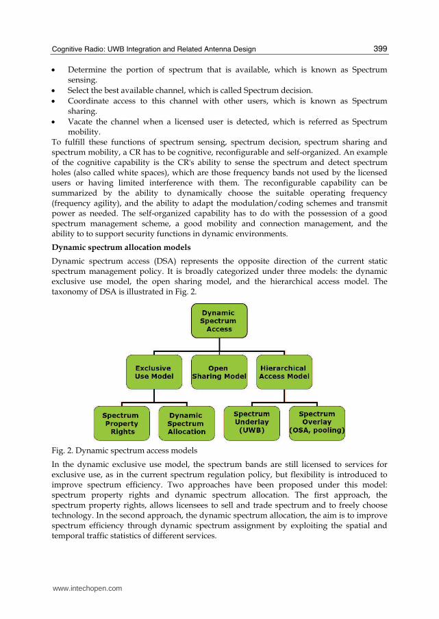
Dynamic spectrum access (DSA) represents the opposite direction of the current static spectrum management policy. It is broadly categorized under three models: the dynamic exclusive use model, the open sharing model, and the hierarchical access model. The taxonomy of DSA is illustrated in Fig. 2.
Fig. 2. Dynamic spectrum access models
In the dynamic exclusive use model, the spectrum bands are still licensed to services for exclusive use, as in the current spectrum regulation policy, but flexibility is introduced to improve spectrum efficiency. Two approaches have been proposed under this model: spectrum property rights and dynamic spectrum allocation. The first approach, the spectrum property rights, allows licensees to sell and trade spectrum and to freely choose technology. In the second approach, the dynamic spectrum allocation, the aim is to improve spectrum efficiency through dynamic spectrum assignment by exploiting the spatial and temporal traffic statistics of different services.
www.intechopen.com
New Trends in Technologies: Control, Management, Computational Intelligence and Network Systems
400
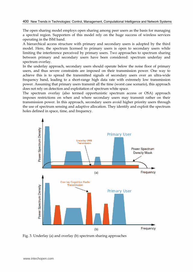
The open sharing model employs open sharing among peer users as the basis for managing a spectral region. Supporters of this model rely on the huge success of wireless services operating in the ISM band. A hierarchical access structure with primary and secondary users is adopted by the third model. Here, the spectrum licensed to primary users is open to secondary users while limiting the interference perceived by primary users. Two approaches to spectrum sharing between primary and secondary users have been considered: spectrum underlay and spectrum overlay. In the underlay approach, secondary users should operate below the noise floor of primary users, and thus severe constraints are imposed on their transmission power. One way to achieve this is to spread the transmitted signals of secondary users over an ultra-wide frequency band, leading to a short-range high data rate with extremely low transmission power. Assuming that primary users transmit all the time (worst case scenario), this approach does not rely on detection and exploitation of spectrum white space. The spectrum overlay (also termed opportunistic spectrum access or OSA) approach imposes restrictions on when and where secondary users may transmit rather on their transmission power. In this approach, secondary users avoid higher priority users through the use of spectrum sensing and adaptive allocation. They identify and exploit the spectrum holes defined in space, time, and frequency.
Fig. 3. Underlay (a) and overlay (b) spectrum sharing approaches
www.intechopen.com
Cognitive Radio: UWB Integration and Related Antenna Design
401
The underlay and overlay approaches in the hierarchical model are illustrated in Fig. 3. They can be employed simultaneously for further spectrum efficiency improvement. Furthermore, the hierarchical model is more compatible with current spectrum management policies and legacy wireless systems as compared to the other two models.
4. Ultra-wideband cognitive radio
Ultra-wideband (UWB) is any wireless technology that has a bandwidth greater than 500 MHz or a fractional bandwidth greater than 0.2. Ultra-wideband systems have been attracting an intense attention from both the industry and academic world since FCC allowed the unlicensed usage of UWB in 2002. UWB is a promising technology for future short- and medium-range high-data-rate wireless communication networks. The most appealing property of UWB is that it is an underlay system, meaning that it can coexist in the same temporal, spatial, and spectral domains with other licensed/unlicensed radios. Other interesting features of UWB include that it has a multi-dimensional flexibility involving adaptable pulse shape, bandwidth, data rate, and transmit power. On top of these, UWB has a low power consumption, and it allows significantly low complexity transceivers leading to a limited system cost. Another very important feature of UWB is providing secure communications. The power spectrum of a UWB transmission is embedded into the noise floor, thus it is very hard to detect. Combined with other higher layer encryption techniques, this feature introduces very secure transmission. UWB systems are allowed to operate in the 3.1–10.6 GHz band without a license requirement (according to the current FCC regulations in the USA), but under very strict transmission power limits. Both indoors and outdoors, UWB systems are not permitted to transmit more than -42 dBm/MHz in the specified band. This limitation ensures that the UWB systems do not interfere to the licensed operators that use various frequency bands in the UWB frequency range. However, FCC regulations could be revised and regulatory agencies may consider to allow UWB systems to transmit with higher powers and offer more freedom to UWB if UWB is combined with CR to give it the ability to sense the spectrum to ensure the absence of licensed users operation in their target bands. There are two common technologies for implementing UWB: the Orthogonal Frequency Division Multiplexing based UWB (UWB-OFDM) and the impulse radio based UWB (IR-UWB). IR-UWB is carried out by transmitting extremely short low-power pulses that are on the order of nanoseconds. An advantage of IR-UWB is that it enables to use various types of modulations, including on-off keying (OOK), pulse amplitude modulation (PAM), pulse shape modulation (PSM), pulse interval modulation (PIM), pulse position modulation (PPM), and phase shift keying (PSK). Time hopping (TH) codes that are specific to each user can be employed by IR-UWB systems for multi-user access. The TH codes, which are specific pseudo-random noise (PN) codes, enable the UWB system to provide access to multiple users conveniently. The multi-user parameters can be adaptively modified according to the change in number of users. To enable more users to communicate, for example, the UWB system can increase the number of chips in each frame at the expense of decreasing each user's data rate. Coherent receivers (such as Rake and correlator receivers) as well as non-coherent ones, such as energy detector and transmitted reference receivers, can be utilized for IR-UWB communications. Along with the flexibility in modulation methods and receiver types, IR-UWB also offers a variety
www.intechopen.com
New Trends in Technologies: Control, Management, Computational Intelligence and Network Systems
402
of options regarding the shapes of the transmitted pulses. IR-UWB systems have an excellent multi-path resolving capability because of the extremely wide frequency band that they occupy. This property makes IR-UWB a precise radar technology as well as a highly accurate ranging and positioning system, in addition to being a communication system. In OFDM-based UWB, orthogonal subcarriers are employed to modulate the transmitted data. In the current multi-band OFDM planning, which divides the entire UWB band into 14 sub-bands, each subband is considered to be 528 MHz and contains 128 subcarriers. The subcarrier spacing is usually chosen to be less than the channel coherence bandwidth. This makes each subcarrier go through a flat fading channel. As a result, the UWB-OFDM receiver needs a simple equalizer implementation to recover the originally transmitted signal. With UWB-OFDM, it is easy to avoid interference to licensed systems. By simply turning off the subcarriers that overlap with the spectra of the licensed system, a UWB-OFDM transmitter can avoid jamming a licensed signal.
UWB features meeting cognitive radio requirements
Though usually associated with the underlay mode, UWB offers the possibility of also being implemented in the overlay mode (Arslan & Sahin, 2007). The difference between the two modes is the amount of transmitted power. In the underlay mode, UWB has a considerably restricted power, which is spread over a wide frequency band. When a UWB system is operating in the underlay mode, it is quite unlikely that any coexisting licensed system is affected from it. On top of this, underlay UWB can employ various narrowband interference avoidance methods. In the overlay mode, however, the transmitted power can be much higher. It actually can be increased to a level that is comparable to the power of licensed systems. But this mode is only applicable if two conditions are met: 1) if the UWB transmitter ensures that the targeted spectrum is completely free of signals of other systems, and 2) if the regulations are revised to allow this mode of operation. UWB can also operate in both underlay and overlay modes simultaneously. This can happen by shaping the transmitted signal so as to make part of the spectrum occupied in an underlay mode and some other parts occupied in an overlay mode. Apparently, in any mode of operation, UWB causes negligible interference to other communication systems. This special feature of UWB makes it very tempting for the realization of cognitive radio. CR should have a high flexibility in determining the spectrum it occupies, because the bands that will be utilized for cognitive communication could vary after each periodic spectrum scan. Flexible spectrum shaping is a part of UWB's nature. In IR-UWB, the occupied spectrum can directly be altered by varying the duration or the form of the short transmitted pulses. In UWB-OFDM, on the other hand, spectrum shaping can be conveniently accomplished by turning some subcarriers on or off according to the spectral conditions. CR systems are should be able to adjust their data rates according to the available bandwidth, which varies according to the utilization of the bands by the licensed systems. CR systems are also expected to provide a solution for the cases when the available bandwidth is so limited that the communication cannot be continued. UWB systems are able to make abrupt changes in their throughput. For example, an IR-UWB system can respond to a decrease in available bandwidth by switching to a different wider pulse shape, and can do the opposite if there is more band to use. In UWB-OFDM, the adjustment of the occupied bandwidth is even simpler. The subcarriers that overlap with the newly occupied bands are turned off, and this way the data rate is decreased, or more subcarriers are used to occupy newly available bands, thus increasing the data rate.
www.intechopen.com

Cognitive Radio: UWB Integration and Related Antenna Design
403
Furthermore, UWB provides an exceptional solution regarding the dropped calls. If UWB is
performed in overlay mode, and in cases when it becomes impossible to continue the
communication, UWB can switch to the underlay mode. Thus, UWB can maintain the
communication link even though it is at a low quality since licensed systems are not affected
by UWB operated in the underlay mode.
The spectral masks that are imposed by the regulatory agencies (such as the FCC in the
USA) are also determinative in spectrum usage in that they set a limit to the transmit power
of wireless systems. UWB offers a satisfactory solution to the adaptable transmit power
requirement of cognitive radio. Both UWB-OFDM and IR-UWB systems can comply with
any set of spectral rules mandated upon the cognitive radio system by adapting their
transmit power.
CR networks should be able to provide multi-user access since there will be a number of
users willing to make use of the same spectrum opportunities at the same time. CR is also
required to be able to modify its multiple access parameters to cope with the changes that
may occur in the overall spectrum occupancy, or with the possible fluctuations in the signal
quality observed by each user.
From the point of adaptive multiple access, UWB is a proper candidate for CR applications
and is very flexible in terms of multiple access. For example, in IR-UWB, the number of
users can be determined by modifying the number of chips in a frame. In UWB-OFDM, on
the other hand, more users can be allowed to communicate by decreasing the subcarriers
assigned to each user.
UWB has information security in its nature. Hence, it can be considered a strong candidate
for CR applications in terms of information security. Underlay UWB is a highly secure
means of exchanging information. If a UWB system is working in the underlay mode,
because of the very low power level, it is impossible for unwanted users to detect even the
existence of the UWB signals. Overlay mode UWB, on the other hand, can also be
considered a safe communication method. In overlay IR-UWB, multiple accessing is enabled
either by time hopping or by direct sequencing. Therefore, receiving a user's information is
only possible if the user's time hopping or spreading code is known. UWB-OFDM also
provides security by assigning different subcarriers to different users. The level of security
can be increased by periodically changing these subcarrier assignments. Apparently, UWB
is a secure way of communicating in both its underlay and overlay modes.
UWB communication can be accomplished by employing very low cost transmitters and
receivers. The transceiver circuitries required to generate and process UWB signals are
inexpensive, and the RF front-end required to send and capture UWB signals are also quite
uncomplicated and inexpensive. This property of UWB makes it very attractive for CR,
which aims at limited infrastructure and transceiver costs.
Adaptive UWB spectral mask
Fig. 4 depicts the UWB spectrum and the bands for some existing and dedicated
narrowband services. UWB signals, which spread over a very wide spectral region at low
power levels near the noise floor, will overlap with some of these systems, such as fixed
satellite, radio astronomy, and the services operating in the U-NII bands. Despite the very
low power level, there have been some concerns that UWB would increase the interference
floor and degrade the performances of licensed users.
www.intechopen.com
New Trends in Technologies: Control, Management, Computational Intelligence and Network Systems
404
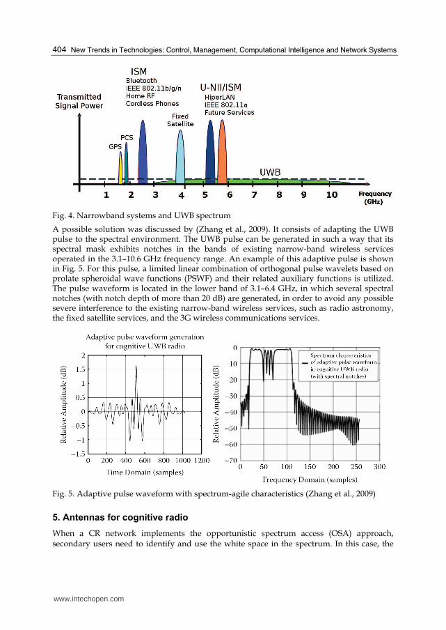
Fig. 4. Narrowband systems and UWB spectrum
A possible solution was discussed by (Zhang et al., 2009). It consists of adapting the UWB pulse to the spectral environment. The UWB pulse can be generated in such a way that its spectral mask exhibits notches in the bands of existing narrow-band wireless services operated in the 3.1–10.6 GHz frequency range. An example of this adaptive pulse is shown in Fig. 5. For this pulse, a limited linear combination of orthogonal pulse wavelets based on prolate spheroidal wave functions (PSWF) and their related auxiliary functions is utilized. The pulse waveform is located in the lower band of 3.1–6.4 GHz, in which several spectral notches (with notch depth of more than 20 dB) are generated, in order to avoid any possible severe interference to the existing narrow-band wireless services, such as radio astronomy, the fixed satellite services, and the 3G wireless communications services.
Fig. 5. Adaptive pulse waveform with spectrum-agile characteristics (Zhang et al., 2009)
5. Antennas for cognitive radio
When a CR network implements the opportunistic spectrum access (OSA) approach, secondary users need to identify and use the white space in the spectrum. In this case, the
www.intechopen.com
Cognitive Radio: UWB Integration and Related Antenna Design
405
transceiver of the CR device should be ended with an antenna system that can simultaneously sense the channel over a wide frequency range and communicate over a narrow band once the operating frequency is determined. If UWB is used as the CR enabling technology, UWB antennas can be employed at the transceiver front-end. In the underlay mode, a UWB antenna can be used to transmit/receive the very-low-power pulse. In the overlay mode, the UWB higher-power pulse could be transmitted if the targeted spectrum is completely free of signals of other systems (time white space), or this pulse should be unique and adaptive with spectral notches to avoid strong interference to existing narrow-band wireless services. In both modes, UWB antennas could still be used, however in the overlay mode UWB antennas with controllable frequency notches are more robust.
CR antennas for opportunistic spectrum access
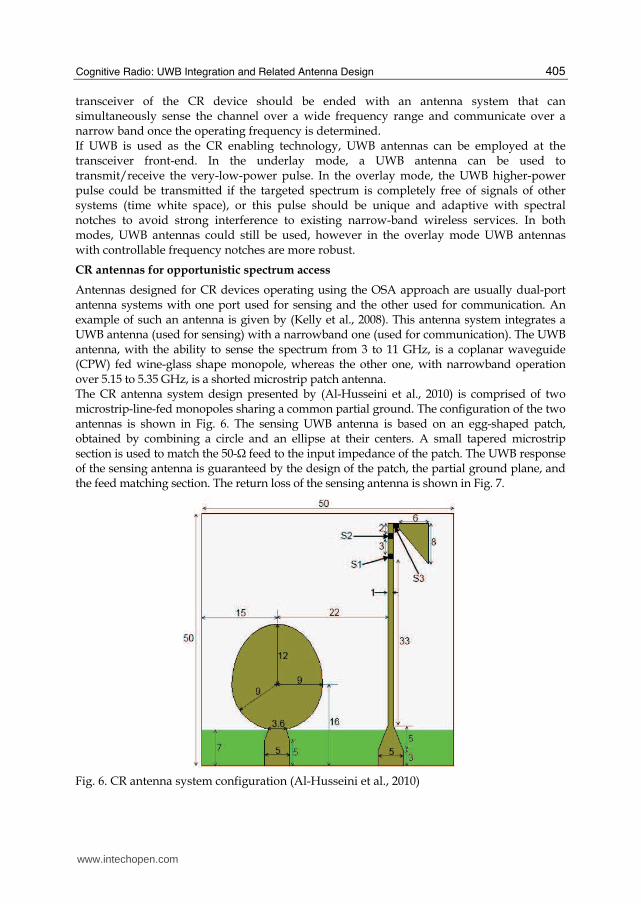
Antennas designed for CR devices operating using the OSA approach are usually dual-port antenna systems with one port used for sensing and the other used for communication. An example of such an antenna is given by (Kelly et al., 2008). This antenna system integrates a UWB antenna (used for sensing) with a narrowband one (used for communication). The UWB antenna, with the ability to sense the spectrum from 3 to 11 GHz, is a coplanar waveguide (CPW) fed wine-glass shape monopole, whereas the other one, with narrowband operation over 5.15 to 5.35 GHz, is a shorted microstrip patch antenna. The CR antenna system design presented by (Al-Husseini et al., 2010) is comprised of two microstrip-line-fed monopoles sharing a common partial ground. The configuration of the two antennas is shown in Fig. 6. The sensing UWB antenna is based on an egg-shaped patch, obtained by combining a circle and an ellipse at their centers. A small tapered microstrip section is used to match the 50-Ω feed to the input impedance of the patch. The UWB response of the sensing antenna is guaranteed by the design of the patch, the partial ground plane, and the feed matching section. The return loss of the sensing antenna is shown in Fig. 7.
Fig. 6. CR antenna system configuration (Al-Husseini et al., 2010)
www.intechopen.com
New Trends in Technologies: Control, Management, Computational Intelligence and Network Systems
406
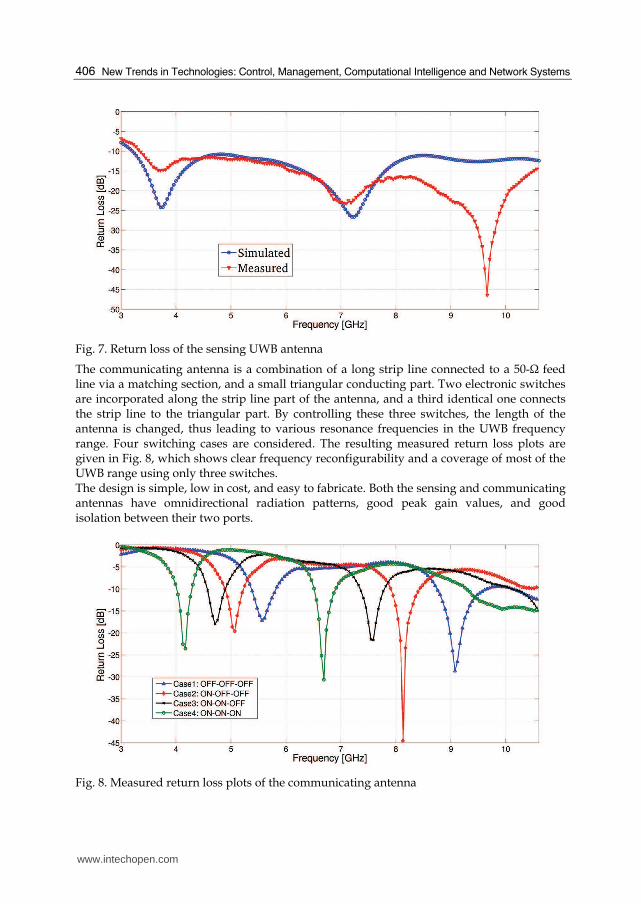
Fig. 7. Return loss of the sensing UWB antenna
The communicating antenna is a combination of a long strip line connected to a 50-Ω feed line via a matching section, and a small triangular conducting part. Two electronic switches are incorporated along the strip line part of the antenna, and a third identical one connects the strip line to the triangular part. By controlling these three switches, the length of the antenna is changed, thus leading to various resonance frequencies in the UWB frequency range. Four switching cases are considered. The resulting measured return loss plots are given in Fig. 8, which shows clear frequency reconfigurability and a coverage of most of the UWB range using only three switches. The design is simple, low in cost, and easy to fabricate. Both the sensing and communicating antennas have omnidirectional radiation patterns, good peak gain values, and good isolation between their two ports.
Fig. 8. Measured return loss plots of the communicating antenna
www.intechopen.com
Cognitive Radio: UWB Integration and Related Antenna Design
407
Antennas for UWB-CR
UWB antennas can be used with UWB-enabled CR. The literature is full of research and
work pertaining to the design of UWB antennas. (Low et al., 2005) presented a UWB knight's
helm shape antenna fabricated on an FR4 board with a double slotted rectangular patch
tapered from a 50-Ω feed line, and a partial ground plane flushed with the feed line. Three
techniques are applied for good impedance matching over the UWB range: 1) the dual slots
on the rectangular patch, 2) the tapered connection between the rectangular patch and the
feed line, and 3) a partial ground plane flushed with feed line. Consistent omnidirectional
radiation patterns and a small group delay characterize this UWB antenna.
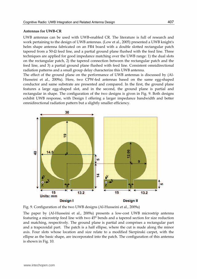
The effect of the ground plane on the performance of UWB antennas is discussed by (Al-
Husseini et al., 2009a). Here, two CPW-fed antennas based on the same egg-shaped
conductor and same substrate are presented and compared. In the first, the ground plane
features a large egg-shaped slot, and in the second, the ground plane is partial and
rectangular in shape. The configuration of the two designs is given in Fig. 9. Both designs
exhibit UWB response, with Design I offering a larger impedance bandwidth and better
omnidirectional radiation pattern but a slightly smaller efficiency.
Fig. 9. Configuration of the two UWB designs (Al-Husseini et al., 2009a)
The paper by (Al-Husseini et al., 2009a) presents a low-cost UWB microstrip antenna
featuring a microstrip feed line with two 45° bends and a tapered section for size reduction
and matching, respectively. The ground plane is partial and comprises a rectangular part
and a trapezoidal part. The patch is a half ellipse, where the cut is made along the minor
axis. Four slots whose location and size relate to a modified Sierpinski carpet, with the
ellipse as the basic shape, are incorporated into the patch. The configuration of this antenna
is shown in Fig. 10.
www.intechopen.com
New Trends in Technologies: Control, Management, Computational Intelligence and Network Systems
408
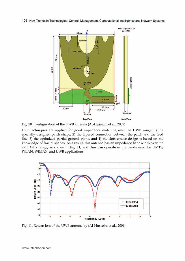
Fig. 10. Configuration of the UWB antenna (Al-Husseini et al., 2009)
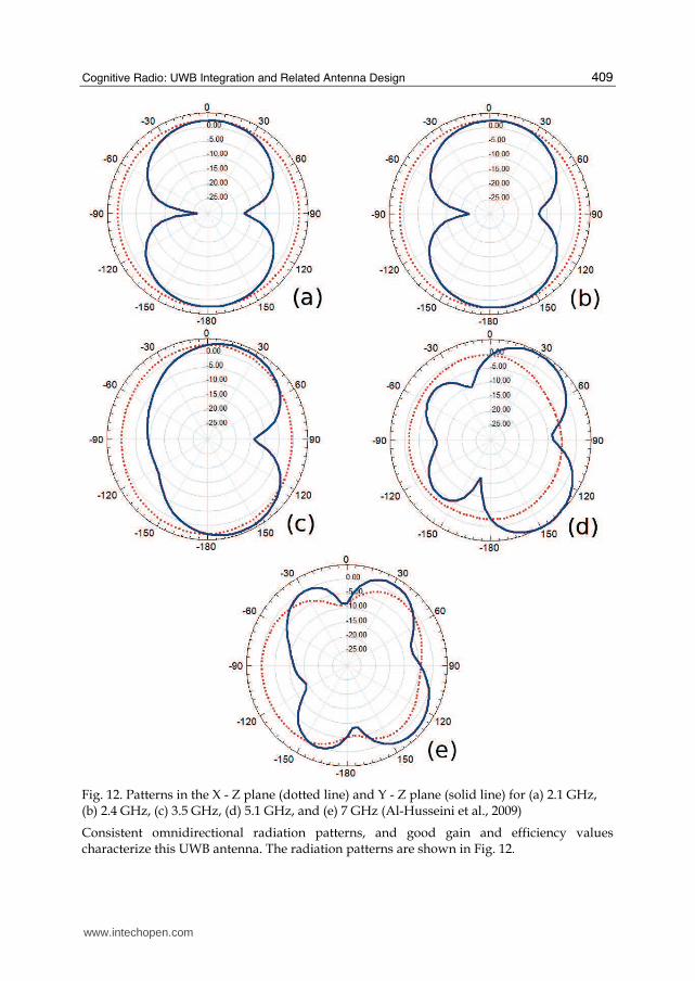
Four techniques are applied for good impedance matching over the UWB range: 1) the specially designed patch shape, 2) the tapered connection between the patch and the feed line, 3) the optimized partial ground plane, and 4) the slots whose design is based on the knowledge of fractal shapes. As a result, this antenna has an impedance bandwidth over the 2–11 GHz range, as shown in Fig. 11, and thus can operate in the bands used for UMTS, WLAN, WiMAX, and UWB applications.
Fig. 11. Return loss of the UWB antenna by (Al-Husseini et al., 2009)
www.intechopen.com
Cognitive Radio: UWB Integration and Related Antenna Design
409
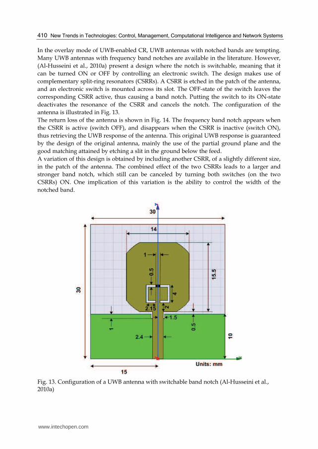
Fig. 12. Patterns in the X - Z plane (dotted line) and Y - Z plane (solid line) for (a) 2.1 GHz, (b) 2.4 GHz, (c) 3.5 GHz, (d) 5.1 GHz, and (e) 7 GHz (Al-Husseini et al., 2009)
Consistent omnidirectional radiation patterns, and good gain and efficiency values characterize this UWB antenna. The radiation patterns are shown in Fig. 12.
www.intechopen.com
New Trends in Technologies: Control, Management, Computational Intelligence and Network Systems
410
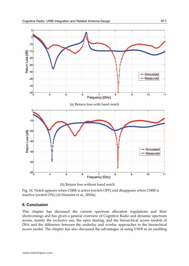
In the overlay mode of UWB-enabled CR, UWB antennas with notched bands are tempting.
Many UWB antennas with frequency band notches are available in the literature. However,
(Al-Husseini et al., 2010a) present a design where the notch is switchable, meaning that it
can be turned ON or OFF by controlling an electronic switch. The design makes use of
complementary split-ring resonators (CSRRs). A CSRR is etched in the patch of the antenna,
and an electronic switch is mounted across its slot. The OFF-state of the switch leaves the
corresponding CSRR active, thus causing a band notch. Putting the switch to its ON-state
deactivates the resonance of the CSRR and cancels the notch. The configuration of the
antenna is illustrated in Fig. 13.
The return loss of the antenna is shown in Fig. 14. The frequency band notch appears when
the CSRR is active (switch OFF), and disappears when the CSRR is inactive (switch ON),
thus retrieving the UWB response of the antenna. This original UWB response is guaranteed
by the design of the original antenna, mainly the use of the partial ground plane and the
good matching attained by etching a slit in the ground below the feed.
A variation of this design is obtained by including another CSRR, of a slightly different size,
in the patch of the antenna. The combined effect of the two CSRRs leads to a larger and
stronger band notch, which still can be canceled by turning both switches (on the two
CSRRs) ON. One implication of this variation is the ability to control the width of the
notched band.
Fig. 13. Configuration of a UWB antenna with switchable band notch (Al-Husseini et al., 2010a)
www.intechopen.com
Cognitive Radio: UWB Integration and Related Antenna Design
411
(a) Return loss with band notch
(b) Return loss without band notch
Fig. 14. Notch appears when CSRR is active (switch OFF) and disappears when CSRR is inactive (switch ON) (Al-Husseini et al., 2010a)
6. Conclusion
This chapter has discussed the current spectrum allocation regulations and their shortcomings and has given a general overview of Cognitive Radio and dynamic spectrum access, mainly the exclusive use, the open sharing, and the hierarchical access models of DSA and the difference between the underlay and overlay approaches in the hierarchical access model. The chapter has also discussed the advantages of using UWB as an enabling
www.intechopen.com
New Trends in Technologies: Control, Management, Computational Intelligence and Network Systems
412
technology for CR. A major part of the chapter has been a survey of the latest work on antenna design for cognitive radio. Two categories of antennas have been included: antennas that could be used for CR when the OSA approach is implemented, and antennas that could be used for UWB-CR. Further research on both categories of antennas is still under way.
7. References
Al-Husseini, M.; Tawk, Y.; El-Hajj, A. & Kabalan, K.Y. (2009). A low-cost microstrip antenna for 3G/WLAN/WiMAX and UWB applications, Proceedings of the 2009 international conference on advances in computational tools for engineering applications (ACTEA’09), pp. 68–70, ISBN 978-1-4244-3833-4, Jul 2009, Zouk Mosbeh, Lebanon
Al-Husseini, M.; Ramadan, A.; Tawk, Y.; El-Hajj, A. & Kabalan, K.Y. (2009). Design and ground plane consideration of a CPW-fed UWB antenna, Proceedings of the 2009 international conference on electrical and electronics engineering (ELECO’09), pp. II-151–II-153, ISBN 978-1-4244-5106-7, Nov 2009, Bursa, Turkey
Al-Husseini, M.; Tawk, Y.; Christodoulou, C.G.; El-Hajj, A. & Kabalan, K.Y. (2010). A simple dual-port antenna system for cognitive radio applications, Proceedings of the 2010 international conference on high performance computing and simulation (HPCS’10), pp. 549–552, Jun-Jul 2010, Caen, France
Al-Husseini, M.; Costantine, J.; Ramadan, A.; Christodoulou, C.G.; Kabalan, K.Y. & El-Hajj A. (2010). Ultrawideband antennas with switchable band notch using complementary split-ring resonators, Proceedings of the 2010 international conference on high performance computing and simulation (HPCS’10), pp. 560–563, Jun-Jul 2010, Caen, France
Arslan, H. & Sahin, M. (2007). UWB-Based Cognitive Radio Networks, In: Cognitive Wireless
Communication Networks, Hossain, E. & Bhargava, V.K., (Ed.), 213−230, Springer US, ISBN 978-0-387-68830-5, New York.
Berlemann, L. & Mangold, S. (2009). Cognitive Radio and Dynamic Spectrum Access, John Wiley & Sons, ISBN 978-0-470-51167-1, West Sussex, United Kingdom.
Chen, K.-C. & Prasad, R. (2009). Cognitive Radio Networks, John Wiley & Sons, ISBN 978-0-470- 69689-7, West Sussex, United Kingdom.
FCC, (2002). Spectrum Policy Task Force Report, Tech. Rep. TR 02-155 Kelly, J.R.; Ebrahimi, E.; Hall, P.S.; Gardner, P. & Ghanem, F. (2008). Combined wideband
and narrowband antennas for cognitive radio applications, Proceedings of the 2008 IET seminar on cognitive radio and software defined radios: technologies and techniques, pp. 1–4, ISBN 978-0-86341-939-3, Sept 2008, London, UK
Low, Z.N.; Cheong, J.H. & Law, C.L. (2005). Low-cost PCB antenna for UWB applications. IEEE Antennas and Wireless Propagation Letters, Vol. 4, Aug 2005, 237–239, ISSN 1536 - 1225 NTIA, (2003). U.S. Frequency Allocation Chart
http://www.ntia.doc.gov/osmhome/allochrt.pdf Zhang, H.; Zhou, X. & Chen, T. (2009). Ultra-wideband cognitive radio for dynamic
spectrum accessing networks, In: Cognitive Radio Networks, Xiao, Y. & Hu, F., (Ed.), 353–382, CRC Press, ISBN 978-1-4200-6420-9, Boca Raton, Florida.
www.intechopen.com
New Trends in Technologies: Control, Management,Computational Intelligence and Network SystemsEdited by Meng Joo Er
ISBN 978-953-307-213-5Hard cover, 438 pagesPublisher SciyoPublished online 02, November, 2010Published in print edition November, 2010
InTech EuropeUniversity Campus STeP Ri Slavka Krautzeka 83/A 51000 Rijeka, Croatia Phone: +385 (51) 770 447 Fax: +385 (51) 686 166www.intechopen.com
InTech ChinaUnit 405, Office Block, Hotel Equatorial Shanghai No.65, Yan An Road (West), Shanghai, 200040, China
Phone: +86-21-62489820 Fax: +86-21-62489821
The grandest accomplishments of engineering took place in the twentieth century. The widespreaddevelopment and distribution of electricity and clean water, automobiles and airplanes, radio and television,spacecraft and lasers, antibiotics and medical imaging, computers and the Internet are just some of thehighlights from a century in which engineering revolutionized and improved virtually every aspect of human life.In this book, the authors provide a glimpse of the new trends of technologies pertaining to control,management, computational intelligence and network systems.
How to referenceIn order to correctly reference this scholarly work, feel free to copy and paste the following:
Mohammed Al-Husseini, Karim Kabalan, Ali El-Hajj and Christos Christodoulou (2010). Cognitive Radio: UWBIntegration and Related Antenna Design, New Trends in Technologies: Control, Management, ComputationalIntelligence and Network Systems, Meng Joo Er (Ed.), ISBN: 978-953-307-213-5, InTech, Available from:http://www.intechopen.com/books/new-trends-in-technologies--control--management--computational-intelligence-and-network-systems/cognitive-radio-uwb-integration-and-related-antenna-design

© 2010 The Author(s). Licensee IntechOpen. This chapter is distributedunder the terms of the Creative Commons Attribution-NonCommercial-ShareAlike-3.0 License, which permits use, distribution and reproduction fornon-commercial purposes, provided the original is properly cited andderivative works building on this content are distributed under the samelicense.


![Mohammed Al-Husseini, Karim Y. Kabalan, Ali El-Hajj and ......taxonomy of DSA is illustrated in Fig. 1 [3]. Figure 1. Dynamic spectrum access models [3] In the dynamic exclusive use](https://img.pdfslide.us/doc/110x75/61244caf5b60bc231c37a41b/mohammed-al-husseini-karim-y-kabalan-ali-el-hajj-and-taxonomy-of-dsa.jpg)


![[Sara Leila Husseini] Early Christian Explanations(BookFi.org)](https://img.pdfslide.us/doc/110x75/563db9f5550346aa9aa17354/sara-leila-husseini-early-christian-explanationsbookfiorg.jpg)