Embed Size (px)
Citation preview

DE - Installierungs-und Gebrauchsanleitungen und Hinweise
EN - Instructions and warnings for installation and use
IT - Istruzioni ed avvertenze per l’installazione e l’uso
FR - Instructions et avertissements pour l’installation et l’utilisation
ES - Instrucciones y advertencias para la instalación y el uso
PL - Instrukcjeiostrzeżeniadoinstalacjiiużytkowania
NL - Aanwijzingen en aanbevelingen voor installatie en gebruik
Photocells
MOONBUSMOFBMOFOB

2
When addressing using the special jumpers, the special “BlueBus” communi-cation system enables the control unit to recognise the photocells and assign them with the correct detection function. Addressing must be carried out on both the TX and RX (and the jumpers set in the same way). Ensure there are no other pairs of photocells with the same address.1. Address the photocells on the basis of the function required, setting the
jumpers as shown in Table 1. Any unused jumpers must be stored in their proper compartment ready for future use, as shown in Figure 6.
Note: Refer to the instruction manual for control units and command inter-faces with “BlueBus” technology for a detailed description of the various operations carried out for each kind of addressing.Note: to rectify interference problems between the various “BlueBUS” devices, position the transmitters and receivers as shown in figures 2a and 2b.
2. Programme the devices using the control unit as described in the paragraph entitled “Recognition of connected devices” in the instruction manual of the various “BlueBus” interfaces or control units.
Note: If the photocell is used to replace an already existing one, the jumpers must be set exactly as they were in the old photocell. It is not necessary to carry out the recognition phase.
3. Adjusting the orientation: it is possible to adjust the orientation of the adjustable MOFOB photocell. This enables the user to achieve a perfect alignment, even if the fastening is not excellent. Proceed as per Figure 8 in order to regulate the orientation. Loosen the screw slightly and move the mobile part slowly. Then tighten the screw. Follow the signals of the “L” indicator: the slower the flashes, the better the centring.
The best centring has been achieved for both the MOFB and MOFOB ver-sions when the indicator flashes very slowly, although performance is also acceptable when flashes are simply slow. However, the centring is at risk when the indicator flashes quickly.
Photocell
FOTO
1) Warnings
This manual has been especially written for use by qualified fit-ters. No information given in this manual can be considered as being of interest to end users! This manual refers to MOFB-MOFOB only and cannot be used for different products.
Read the instructions carefully before installing this product. Improper use of the said product or errors made during connection may jeopardise the correct operation of the device and the safety of the persons using it.
• The photocell must operate exclusively via direct TX-RX interpolation. It must not be used for reflection purposes.
• The photocell must be fastened securely to a rigid surface, which does not vibrate.
• Use the wires specified in the manuals for control units for the electrical connections.
• The MOFB-MOFOB photocells can only be connected up to control units which use “BlueBus” technology.
The MOFB and MOFOB photocells are detectors (type D according to EN standard EN 12453) which can be used for automations for gates. They reveal obstacles situated on the optical axis between the transmitter (TX) and receiver (RX).The photocells are equipped with a “BlueBus” communication system. This means they can easily be connected up to the control unit of all the devices using two wires only. All the photocells are quite simply connected in paral-lel, and the addressing jumpers selected according to the function required (see Table 1).
The non-adjustable version of the MOFB can be used as long as the surface the device will be fastened to is flat and allows correct TX-RX centring. The manufacturers recommend using the adjutsable MOFOB version whenever this centring is not directly possible.The MOFB and MOFOB photocells can be used along with the new “FT210B” series of devices (see figures 2a and 2b). The FT210B device uses the “Blue-BUS” technology and resolves problems related to the electrical connection of sensitive edges on the mobile leaf (for further details consult the FT210B use manual).
2) Description and Intended Use
3) Installation
Only carry out installation work once the electricity supply to the system has been switched off. Disconnect any buffer batteries present.
Begin the installation process by checking the following points:1. As it is not possible to adjust the orientation when using fixed MOFB pho-
tocells, fitters must check that the surface the device will be fastened to will enable correct TX-RX centring. Fasten the photocells as shown in Figures 1a and 1b.
2. Position the photocells on the basis of their detection functions according to the type of automation used. Check the position in Figures 2, 3 and 4, and fit the jumpers as per Table 1. If the photocell needs to be used as an
opening device (see figures 2a, 2b, 3, 4 and the FA1 and FA2 addresses in table 1), cut the jumper between points “A” both on the TX and on the RX as shown in fig. 5.
3. Connect the electric cable to the appropriate TX and RX terminals. From an electrical viewpoint, TX and RX must be both connected in parallel as shown in Figure 5, and to the “BlueBus” terminal of the interfaces or control units. It is not necessary to observe any polarity.
!
!
4) Addressing and recognition of devices
Table 1
Jumpers
FOTO II
FOTO 1
FOTO 1 II
FOTO 2
FOTO 2 II
FOTO 3
FA1(Cut jumper A on the TX and
RX as shown in fig. 5)
FA2(Cut jumper A on the TX and
RX as shown in fig. 5)

3
LED “L”Off
3 quick flashes and a second’s pauseVery slow flashing
Slow flashingQuick flashing
Very quick flashing
Always ON
StatusThe photocell is either not powe-red or is faultyDevice not recognised by the control unitThe TX transmits regularlyThe RX receives a perfect signal.The RX receives a fair signalThe RX receives a poor signal
The RX receives a very poor signalThe RX does not receive any signal at all
ActionMake sure the voltage for the photocell terminals is approximately 8-12 Vdc. If the voltage is correct, the photocell is probably broken. Repeat the learning procedure on the control unit. Make sure that all the photocell pairs have different addressesNormal operation
Normal operationNormal operation. However, it is best to check the TX-RX alignment and make sure the glasses are cleanIt is at the very limit of normal operation. Check the TX-RX alignment and make sure the glasses are clean.Make sure that the LED on TX flashes once slowly. Check to see if there is an obstacle between TX and RX. Check the TX-RX alignment
Table 2
After the recognition phase, check that the LED on the photocell starts flashing (both on TX and RX). Check Table 2 for the state of the photocell based on the way LED “L” flashes.
5) Testing and checking operation
Warning: After you have added or removed any photocells, the automation system must be tested again according to the directions contained in the installation manual.
To check the photocells and make sure that there is no interference with other devices, pass a 5 cm diameter, 30 cm long cylinder on the optical axis, first near TX, then near RX and finally at the mid-point between them (shown in Figure 9) and make sure that in all these cases the device is triggered, switch-ing from the active to the alarm status and vice-versa; finally, that it causes
the intended action in the control unit, for example that it causes the reversal of the movement during the closing manoeuvre.
To check the photocells as an optical presence sensor (type D),according to the EN 12445 standard, is performed with the 700x300x200mm test parallelepiped with 3 opaque black sides and 3 polished white sides or mir-rored as shown in figure 10 following that stipulated by chapter 7 of the EN 12445:2000 standard (or enclosure A of prEN 12445:2005).
L
The photocells do not require any special maintenance work. However, it is necessary to check them at least once every six months in order to evaluate their condition (presence of damp, oxides, etc.). The outer covering and lenses must be cleaned, then testing carried out again, as described in the previous paragraph.
The photocells have been studied and designed in order that that they will operate in normal conditions for at least 10 years. It is, therefore, necessary to increase the frequency of the maintenance work carried out on the said photocells after this period of time has elapsed.
6) Maintenance
6.1) Disposal As for the installation, the disposal of the product at the end of its effective life, must be performed by qualified personnel. This product is made of vari-ous types of material, some of which can be recycled while others must be disposed of. Enquire about the recycling or disposal systems available for this product category in compliance with regulations locally in force.
Warning: some parts of the product may contain polluting or hazardous substances that, if incorrectly disposed of, could have a damaging effect on the environment or on the health of individuals.
As indicated by the symbol in figure 11, this product must not be disposed of in household waste. Per-form “separated collection” for disposal in compli-ance with regulations locally in force, or return the product to the manufacturer when purchasing a replacement.
Heavy fines may be imposed by local laws for the illegal disposal of this product.
7) Technical characteristics
Nice S.p.a., in order to improve its products, reserves the right to modify their technical characteristics at any time without prior notice. In any case, the manu-facturer guarantees their functionality and fitness for the intended purposes. Note: all technical specifications refer to a temperature of 20°C. Product type Detector for gate and door automation systems (type D according to EN standard 12453), consisting in a “TX” transmitter and “RX” receiver.Technology employed TX-RX direct optical interpolation with modulated infrared ray.Power supply/output The device can only be connected to “BlueBus” networks, from which it receives its power supply and sends output signals.Absorbed power 1 “BlueBus” unit.Detection capacity Opaque objects (larger than 50 mm) located on the optical axis between TX and RX, which move more slowly than 1.6m/s.TX transmission angle 20° +/- 25%RX reception angle Approximately 20°.Adjustability of the MOFOB photocell Approximately 30° along the horizontal and vertical axes. Useful range Up to 15m for a maximum TX-RX misalignment of ± 5° (the device can detect and signal an obstacle even in particularly bad weather conditions).Maximum range (under optimum conditions) Up to 30m for a maximum TX-RX misalignment of ± 5°. Maximum cable length Up to 50 m.Addressing possibility Up to 7 detectors with the protection function, and 2 with the opening command function. The automatic synchronism prevents any interference among the various detectors.Use in acid, saline or potentially Noexplosive atmospheres Mounting Vertically wall-mountedProtection class for casing IP55Operating temperature 20 ÷55°CDimensions / weight for MOFB 69 x 78 h 25mm / 50g for MOFOB 69 x 78 h 37mm / 75g
11
EN

4
Il particolare sistema di comunicazione “BlueBus” consente, tramite l’indiriz-zamento con gli appositi ponticelli, il riconoscimento delle fotocellule da parte della centrale e di assegnare la corretta funzione di rilevazione. L’operazione di indirizzamento va fatta sia sul TX che sul RX (ponendo i ponticelli nello stesso modo) verificando che non vi siano altre coppie di fotocellule con lo stesso indirizzo.1. Indirizzare le fotocellule in base alla funzione richiesta ponendo i ponticelli
secondo la tabella 1. Riporre gli eventuali ponticelli non usati nel vano riser-vato per utilizzi futuri, come in figura 6.
Nota: per la descrizione dettagliata delle varie funzioni eseguite ad ogni tipo di indirizzamento, si rimanda ai manuali d’uso delle centrali e interfacce di comando con tecnologia “BlueBus”.Nota: Per ovviare a problemi di interferenze tra i vari dispositivi “BlueBus”, disporre i trasmettitori e i ricevitori delle fotocellule, come indicato nelle figure 2a e 2b.
2. Sulla centrale, eseguire la procedura di programmazione dei dispositivi, come riportato nel paragrafo “Apprendimento dispositivi collegati” nel manuale d’uso delle varie interfacce o centrali di comando “BlueBus”.
Nota: Se la fotocellula viene usata in sostituzione di una già esistente, i pon-ticelli andranno posti esattamente com’erano nella fotocellula sostituita e non è necessaria la fase di apprendimento.
3. Regolazione dell’orientamento: Nella fotocellula orientabile MOFOB è disponibile la regolazione dell’orientamento che consente di ottenere un perfetto allineamento anche quando il fissaggio non è ottimale. Per regolare l’orientamento procedere come indicato in figura 8. Allentare leggermente la vite e far oscillare lentamente la parte mobile, infine richiudere la vite. Seguire la segnalazione dell’indicatore “L”: minore è la velocità del lampeg-gio e migliore è la centratura. Su entrambe le versioni MOFB e MOFOB, la centratura ottimale si ha quando l’indicatore lampeggia molto lentamente, comunque accettabile quando lampeggia lentamente, a rischio invece quando l’indicatore lampeggia velocemente.
Fotocellula
FOTO
1) Avvertenze
Il presente manuale è destinato solamente al personale tecnico qualificato per l’installazione. Nessuna informazione contenuta nel presente fascicolo può essere considerata d’interesse per l’utilizza-tore finale! Questo manuale è riferito alle fotocellule MOFB-MOFOB e non deve essere utilizzato per prodotti diversi. È opportuno leggere attentamente le istruzioni prima di eseguire l’installa-zione: l’uso improprio o un errore di collegamento potrebbe pregiudicare la sicurezza o il corretto funzionamento del dispositivo.
• La fotocellula deve funzionare esclusivamente per interpolazione diretta TX-RX; è vietato l’uso per riflessione.
• La fotocellula va fissata in modo permanente su una superficie rigida e senza vibrazioni.
• Utilizzare per i collegamenti elettrici, conduttori adeguati come riportato nei manuali delle centrali.
• Le fotocellule MOFB-MOFOB possono essere collegate solo a centrali dotate di tecnologia “BlueBus”.
Le fotocellule MOFB e MOFOB sono rilevatori di presenza (tipo D secondo la norma EN 12453) utilizzabili in automatismi per cancelli e permettono di rilevare ostacoli presenti sull’asse ottico tra trasmettitore (TX) e ricevitore (RX). Le fotocellule sono dotate di un tipo di comunicazione “BlueBus” che consen-te un facile collegamento alla centrale di tutti i dispositivi con soli due fili. Le fotocellule vengono semplicemente collegate tutte in parallelo e, a seconda della funzione richiesta, vengono selezionati i ponticelli di indirizzamento (vedere tabella 1).La versione non orientabile MOFB è utilizzabile in tutti quei casi, in cui le
superfici di fissaggio sono piane e permettano una corretta centratura TX-RX; dove tale centratura non sia direttamente possibile, si consiglia l’utilizzo della versione orientabile MOFOB.Le fotocellule MOFB e MOFOB sono utilizzabili assieme alla nuova serie di dispositivi “FT210B” (vedere figure 2a e 2b). FT210B è un dispositivo con tec-nologia “BlueBUS” e consente di risolvere il problema dei collegamenti elettrici di bordi sensibili posti su ante in movimento (per una descrizione dettagliata, si rimanda al manuale d’uso del dispositivo FT210B).
2) Descrizione e destinazione d’uso
3) Installazione
Tutte le operazioni d’installazione vanno eseguite in assenza di tensione all’impianto; nel caso sia presente la batteria tampone, è necessario scollegarla.
Procedere con l’installazione, verificando i seguenti punti:1. Quando si utilizza la fotocellula fissa MOFB non essendo disponibile la
regolazione dell’orientamento occorre accertarsi che la superfici di fissag-gio permettano una corretta centratura TX-RX. Effettuare il fissaggio delle fotocellule come indicato in fig. 1a e 1b.
2. A seconda del tipo di automazione, posizionare le fotocellule in base alle funzioni di rilevazione. Verificare nelle figure 2, 3 e 4, le posizioni previste e porre i ponticelli secondo la tabella 1.
Se richiesta la funzione di fotocellula come dispositivo di apertura (vedere figure 2a ,2b, 3, 4 ed gli indirizzi FA1 e FA2 in tabella 1), tagliare il ponticello tra i punti “A” sia su TX che su RX, come indicato in fig. 5.
3. Collegare il cavo elettrico negli appositi morsetti sia del TX che del RX. Dal punto di vista elettrico, TX ed RX vanno collegati in parallelo tra loro (come mostrato nella figura 5) e al morsetto “BlueBus” delle interfacce o centrali di comando. Non è necessario rispettare alcuna polarità.
!
!
4) Indirizzamento e apprendimento dei dispositivi
Tabella 1
Ponticelli
FOTO II
FOTO 1
FOTO 1 II
FOTO 2
FOTO 2 II
FOTO 3
FA1(tagliare ponticello A su TX e
RX, come da fig. 5)
FA2(tagliare ponticello A su TX e
RX, come da fig. 5)
I
5
LED “L”Spento
3 lampeggi veloci e 1 secondo di pausaLampeggio molto lento
Lampeggio lentoLampeggio veloce
Lampeggio velocissimo
Sempre acceso
StatoLa fotocellula non è alimentata oppure è guasta
Dispositivo non appreso dalla centrale di comandoIl TX trasmette regolarmente.L’RX riceve un segnale ottimoL’RX riceve un segnale buonoL’RX riceve un segnale scarso
L’RX riceve un segnale pessimo
L’RX non riceve alcun segnale
AzioneVerificare che sui morsetti della fotocellula sia presente una tensione di circa 8–12 Vdc; se la tensione è corretta è probabile che la fotocellula sia guastaRipetere la procedura di apprendimento dalla centrale. Verificare che tutte le coppie di fotocellula abbiano indirizzi diversi Funzionamento normale
Funzionamento normaleFunzionamento normale ma è il caso di verificare l’allineamento TX-RX e la corretta pulizia dei vetriniÉ al limite del funzionamento normale, occorre verificare l’allineamento TX-RX e la corretta pulizia dei vetriniVerificare che il LED sul TX esegua un lampeggio molto lento. Verificare se c’è un ostacolo tra TX e RX; verificare l’allineamento TX - RX
Tabella 2
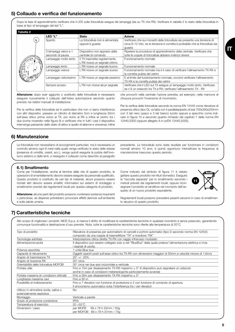
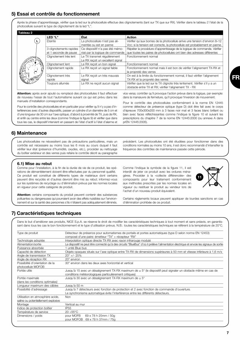
Dopo la fase di apprendimento verificare che il LED sulla fotocellula esegua dei lampeggi (sia su TX che RX). Verificare in tabella 2 lo stato della fotocellula in base al tipo di lampeggio del led “L”.
5) Collaudo e verifica del funzionamento
Attenzione: dopo aver aggiunto o sostituito delle fotocellule è necessario eseguire nuovamente il collaudo dell’intera automazione secondo quanto previsto nei relativi manuali di installazione.
Per la verifica delle fotocellule ed in particolare che non vi siano interferenze con altri dispositivi, passare un cilindro di diametro 5cm e lunghezza 30cm sull’asse ottico prima vicino al TX, poi vicino al RX e infine al centro tra i due (come mostrato nella figura 9) e verificare che in tutti i casi il dispositivo intervenga passando dallo stato di attivo a quello di allarme e viceversa; infine
che provochi nella centrale l’azione prevista; ad esempio: nella manovra di chiusura provochi l’inversione di movimento.
Per la verifica delle fotocellule secondo la norma EN 12445 come rilevatore di presenza ottico (tipo D), va fatta con il parallelepipedo di test 700x300x200mm con 3 lati nero opaco e 3 lati bianco lucido oppure a specchio come indi-cato in figura 10 e secondo quanto richiesto dal capitolo 7 della norma EN 12445:2000 (oppure allegato A in prEN 12445:2005).
L
Le fotocellule non necessitano di accorgimenti particolari, ma è necessaria un controllo almeno ogni 6 mesi nella quale venga verificato lo stato delle stesse (presenza di umidità, ossidi, ecc.), venga quindi eseguita la pulizia dell’invo-lucro esterno e delle lenti, e rieseguito il collaudo come descritto al paragrafo
precedente. Le fotocellule sono state studiate per funzionare in condizioni normali almeno 10 anni, è quindi opportuno intensificare la frequenza di manutenzione trascorso questo periodo.
6) Manutenzione
7) Caratteristiche tecniche
Allo scopo di migliorare i prodotti, NICE S.p.a. si riserva il diritto di modificare le caratteristiche tecniche in qualsiasi momento e senza preavviso, garantendo comunque funzionalità e destinazione d’uso previste. Nota: tutte le caratteristiche tecniche sono riferite alla temperatura di 20°C. Tipo di prodotto Rilevatore di presenza per automatismi di cancelli e portoni automatici (tipo D secondo norma EN 12453) composto da una coppia di trasmettitore “TX” e ricevitore “RX”Tecnologia adottata Interpolazione ottica diretta TX-RX con raggio infrarosso modulatoAlimentazione/uscita Il dispositivo può essere collegato solo a reti “BlueBus” dalla quale preleva l’alimentazione elettrica e invia i segnali di uscita.Potenza assorbita 1 unità Blue busCapacità di rilevamento Oggetti opachi posti sull’asse ottico tra TX-RX con dimensioni maggiori di 50mm e velocità minore di 1,6m/sAngolo di trasmissione TX 20° +/- 25%Angolo di ricezione RX 20° circa Orientabilità della fotocellula MOFOB 30° circa nei due assi orizzontale e verticalePortata utile Fino a 15m per disassamento TX-RX massimo ± 5° (il dispositivo può segnalare un ostacolo anche in caso di condizioni metereologiche particolarmente avverse)Portata massima (in condizioni ottimali) Fino a 30m per disassamento TX-RX massimo ± 5°Lunghezza massima cavi Fino a 50 m Possibilità di Indirizzamento Fino a 7 rilevatori con funzione di protezione e 2 con funzione di comando di apertura. Il sincronismo automatico evita l’interferenza fra i vari rilevatoriUtilizzo in atmosfera acida, salina o Nopotenzialmente esplosiva Montaggio Verticale a pareteGrado di protezione contenitore IP55Temperatura di esercizio 20 ÷55°CDimensioni / peso per MOFB 69 x 78 h 25mm / 50g per MOFOB 69 x 78 h 37mm / 75g
6.1) Smaltimento Come per l’installazione, anche al termine della vita di questo prodotto, le operazioni di smantellamento devono essere eseguite da personale qualificato.Questo prodotto è costituito da vari tipi di materiali, alcuni possono essere riciclati altri devono essere smaltiti; informatevi sui sistemi di riciclaggio o smaltimento previsti dai regolamenti locali per questa categoria di prodotto.
Attenzione: alcune parti del prodotto possono contenere sostanze inquinanti o pericolose, se disperse potrebbero provocare effetti dannosi sull’ambiente e sulla salute umana.
Come indicato dal simbolo di figura 11 è vietato gettare questo prodotto nei rifiuti domestici. Eseguire la “raccolta separata” per lo smaltimento secondo i metodi previsti dai regolamenti locali; oppure ricon-segnare il prodotto al venditore nel momento dell’ac-quisto di un nuovo prodotto equivalente.
Regolamenti locali possono prevedere pesanti sanzioni in caso di smaltimen-to abusivo di questo prodotto.
11
IT

6
Le système particulier de communication “BlueBus” permet, à travers l’adres-sage à l’aide des cavaliers, la reconnaissance des photocellules de la part de la logique et d’attribuer la fonction de détection correcte. L’opération d’adres-sage doit être faite tant sur le TX que sur le RX (en mettant les cavaliers dans la même position) en vérifiant qu’il n’y a pas d’autres paires de photocellules ayant la même adresse.1. Adresser les photocellules suivant la fonction demandée en positionnant
les cavaliers comme l’indique le tableau 1. Remettre les cavaliers inutilisés dans le logement réservé pour des utilisa-
tions futures, comme sur la figure 6.
Note: Pour la description détaillée des diverses fonctions exécutées à chaque type d’adressage, nous renvoyons aux manuels d’instructions des logiques de commande et interfaces de commande avec technologie “BlueBus”.Note: Pour éviter les problèmes d’interférence entre les différents dispositifs «BlueBus», placer les émetteurs et les récepteurs des photocellules, suivant les indications des figures 2a et 2b.
2. Sur la logique de commande, effectuer la procédure de programmation des dispositifs comme l’indique le paragraphe “Apprentissage dispositifs connectés” dans le manuel d’instructions des diverses interfaces ou logiques de commande “BlueBus”.
Note: si la photocellule est utilisée à la place d’une pré-existante, les cavaliers devront être positionnés exactement comme ils l’étaient pour la photocellule remplacée et la phase d’apprentissage n’est pas nécessaire.
3. Réglage de l’orientation: la photocellule orientable MOFOB dispose du réglage de l’orientation qui permet d’obtenir un alignement parfait même quand la fixation n’est pas parfaite. Pour régler l’orientation, procéder comme l’indique la figure 8. Desserrer légèrement la vis et faire osciller lentement la partie mobile, puis serrer enfin la vis. Suivre la signalisation de la led “L”: plus le clignotement est lent et meilleur est le centrage. Sur les deux versions MOFB et MOFOB, le centrage idéal s’obtient quand la led clignote très lentement, il est acceptable toutefois quand elle clignote lentement, mais est par contre à risque quand elle clignote rapidement.
Photocellule
FOTO
1) Avertissements
Ce manuel est destiné exclusivement au personnel technique qua-lifié pour l’installation; aucune information contenue dans ce fascicule ne peut être considérée comme intéressante pour l’utilisateur final! Ce manuel se réfère aux photocellules MOFB-MOFOB et ne doit pas être utilisé pour des produits différents.
Il est opportun de lire attentivement les instructions avant d’effectuer l’installa-tion: l’utilisation impropre ou une erreur de connexion pourrait compromettre le fonctionnement correct du dispositif.
• La photocellule doit fonctionner exclusivement par interpolation directe TX-RX; l’utilisation par réflexion est interdite.
• La photocellule doit être fixée de façon permanente sur une surface rigide et sans vibrations.
• Utiliser pour les connexions électriques des conducteurs adéquats confor-mément aux indications données dans les manuels des logiques de com-mande.
• Les photocellules MOFB-MOFOB peuvent être connectées uniquement à des logiques de commande avec technologie “BlueBus”.
Les photocellules MOFB et MOFOB sont des détecteurs de présence (type D selon la norme EN 12453) utilisables dans des automatismes pour portails et permettent de détecter des obstacles présents sur l’axe optique entre l’émetteur (TX) et le récepteur (RX).Les photocellules sont munies d’un type de communication “BlueBus” qui permet une connexion aisée de tous les dispositifs à la logique de commande en n’utilisant que deux fils. Les photocellules sont simplement connectées toutes en parallèle et les cavaliers d’adressage sont sélectionnés suivant la fonction demandée (voir tableau 1).La version non orientable MOFB est utilisable dans tous les cas où les sur-
faces de fixation sont planes et permettent un centrage TX-RX correct; quand ce centrage n’est pas possible directement, il est conseillé d’opter pour la version orientable MOFOB.Les photocellules MOFB et MOFOB sont utilisables avec la nouvelle série de dispositifs “FT210B” (voir figures 2a et 2b). FT210B est un dispositif avec technologie « BlueBUS » qui permet de résoudre le problème des connexions électriques de bords sensibles placés sur les vantaux en mouvement (sur le parties mobiles)(pour une description détaillée, nous renvoyons à la notice technique d’utilisation du dispositif FT210B).
2) Description et application
3) Installation
Toutes les opérations d’installation sont effectuées sans tension dans l’installation; si la batterie tampon est présente, il faut la décon-necter.
Procéder à l’installation en vérifiant les points suivants:1. Quand on utilise la photocellule fixe MOFB, le réglage de l’orientation
n’étant pas disponible, il faut s’assurer que la surface de fixation permet un centrage TX-RX correct.
Effectuer la fixation des photocellules comme l’indiquent les fig. 1a et 1b.2. Suivant le type d’automatisme, positionner les photocellules suivant les
fonctions de détection. Sur les figures 2, 3 et 4, vérifier les positions pré-
vues et mettre les cavaliers comme l’indique le tableau 1.Si la fonction de photocellule comme dispositif d’ouverture est requise (voir figures 2a ,2b, 3, 4 et les adresses FA1 et FA2 dans le tableau 1), éliminer le cavalier entre les points « A » tant sur TX que sur RX, comme l’indique la fig. 5.
3. Connecter le câble électrique dans les bornes prévues à cet effet tant du TX que du RX. Du point de vue électrique, TX et RX doivent être connectés en parallèle entre eux (comme l’indique la figure 5) et à la borne “BlueBus” des interfaces ou des logiques de commande.
Il n’est pas nécessaire de respecter une polarité quelconque
!
!
4) Adressage et apprentissage des dispositifs
Tableau 1
Cavaliers
FOTO II
FOTO 1
FOTO 1 II
FOTO 2
FOTO 2 II
FOTO 3
FA1(Éliminer le cavalier A sur TX et RX, comme sur la fig. 5)
FA2(Éliminer le cavalier A sur TX et RX, comme sur la fig. 5)
7
LED “L”Éteinte
3 clignotements rapides et 1 seconde de pauseClignotement très lent
Clignotement lentClignotement rapide
Clignotement très rapide Toujours allumée
ÉtatLa photocellule n’est pas ali-mentée ou est en panneCe dispositif n’a pas été mémo-risé par la logique de commande Le TX transmet régulièrementLe RX reçoit un excellent signalLe RX reçoit un bon signalLe RX reçoit un signal faible
Le RX reçoit un très mauvais signalLe RX ne reçoit aucun signal
ActionVérifier qu’aux bornes de la photocellule arrive une tension d’environ 8–12 Vcc; si la tension est correcte, la photocellule est probablement en panne.Répéter la procédure d’apprentissage de la logique de commande. Vérifier que toutes les paires de photocellules ont bien des adresses différentes Fonctionnement normal
Fonctionnement normalFonctionnement normal mais il est bon de vérifier l’alignement TX-RX et la propreté des verresOn est à la limite du fonctionnement normal, il faut vérifier l’alignement TX-RX et la propreté des verresVérifier que la led sur le TX clignote très lentement. Vérifier s’il y a un obstacle entre TX et RX; vérifier l’alignement TX - RX
Tableau 2
Après la phase d’apprentissage, vérifier que la led sur la photocellule effectue des clignotements (tant sur TX que sur RX). Vérifier dans le tableau 2 l’état de la photocellule suivant le type de clignotement de la led “L”.
5) Essai et contrôle du fonctionnement
Attention: après avoir ajouté ou remplacé des photocellules il faut effectuer de nouveau l’essai de tout l’automatisme suivant ce qui est prévu dans les manuels d’installation correspondants.
Pour le contrôle des photocellules et en particulier pour vérifier qu’il n’y a pas d’in-terférences avec d’autres dispositifs, passer un cylindre d’un diamètre de 5 cm et d’une longueur de 30 cm sur l’axe optique, d’abord à proximité de TX, puis de RX, et enfin au centre entre les deux (comme l’indique la figure 9) et vérifier que dans tous les cas, le dispositif intervient en passant de l’état d’actif à l’état d’alarme et
vice versa; contrôler qu’il provoque l’action prévue dans la logique, par exemple: dans la manœuvre de fermeture, qu’il provoque l’inversion de mouvement.
Pour le contrôle des photocellules conformément à la norme EN 12445 comme détecteur de présence optique (type D) doit être fait avec le corps d’épreuve 700x300x200 mm à 3 faces noir mat et 3 faces blanc brillant ou bien avec faces réfléchissantes comme l’indique la figure 10 et suivant les prescriptions du chapitre 7 de la norme EN 12445:2000 (ou annexe A dans prEN 12445:2005).
L
Les photocellules ne nécessitent pas de précautions particulières, mais un contrôle est nécessaire au moins tous les 6 mois au cours duquel il faut vérifier leur état (présence d’humidité, oxydes, etc.), procéder au nettoyage du boîtier extérieur et des verres puis refaire le contrôle décrit au paragraphe
précédent. Les photocellules ont été étudiées pour fonctionner dans des conditions normales au moins 10 ans, il est donc recommandé d’intensifier la fréquence des contrôles de maintenance passée cette période.
6) Maintenance
7) Caractéristiques techniques
Dans le but d’améliorer ses produits, NICE S.p.A. se réserve le droit de modifier les caractéristiques techniques à tout moment et sans préavis, en garantis-sant dans tous les cas le bon fonctionnement et le type d’utilisation prévus. N.B.: toutes les caractéristiques techniques se réfèrent à la température de 20°C. Type de produit Détecteur de présence pour automatismes de portails et portes automatiques (type D selon norme EN 12453) composé d’une paire: émetteur “TX” + récepteur “RX”Technologie adoptée Interpolation optique directe TX-RX avec rayon infrarouge moduléAlimentation/sortie Le dispositif ne peut être connecté qu’à des circuits “BlueBus” d’où il prélève l’alimentation électrique et envoie les signaux de sortiePuissance absorbée 1 unité Blue busCapacité de détection Objets opaques situés sur l’axe optique entre TX-RX de dimensions supérieures à 50 mm et vitesse inférieure à 1,6 m/sAngle de transmission TX 20° +/- 25%Angle de réception RX 20° environPossibilité d’orientation de la 30° environ dans les deux axes horizontal et verticalphotocellule MOFOBPortée utile Jusqu’à 15 avec un désalignement TX-RX maximum de ± 5° (le dispositif peut signaler un obstacle même en cas de conditions météorologiques particulièrement critiques) Portée maximale Jusqu’à 30 avec un désalignement TX-RX maximum de ± 5° (dans les conditions optimales) Longueur maximum des câbles Jusqu’à 50 mPossibilité d’adressage Jusqu’à 7 détecteurs avec fonction de protection et 2 avec fonction de commande d’ouverture. Le synchronisme automatique évite l’interférence entre les différents détecteurs.Utilisation en atmosphère acide, Nonsaline ou potentiellement explosiveMontage Vertical au murIndice de protection boîtier IP55Température de service 20 ÷55°CDimensions / poids pour MOFB 69 x 78 h 25mm / 50g pour MOFOB 69 x 78 h 37mm / 75g
6.1) Mise au rebut Comme pour l’installation, à la fin de la durée de vie de ce produit, les opé-rations de démantèlement doivent être effectuées par du personnel qualifié.Ce produit est constitué de différents types de matériaux dont certains peuvent être recyclés et d’autres devront être mis au rebut; informez-vous sur les systèmes de recyclage ou d’élimination prévus par les normes locales en vigueur pour cette catégorie de produit.
Attention: certains composants du produit peuvent contenir des substances polluantes ou dangereuses qui pourraient avoir des effets nuisibles sur l’environ-nement et sur la santé des personnes s’ils n’étaient pas adéquatement éliminés.
Comme l’indique le symbole de la figure 11, il est interdit de jeter ce produit avec les ordures ména-gères. Procéder à la «collecte différenciée» des composants pour leur traitement conformément aux méthodes prescrites par les normes locales en vigueur ou restituer le produit au vendeur lors de l’achat d’un nouveau produit équivalent.
Certains règlements locaux peuvent appliquer de lourdes sanctions en cas d’élimination prohibée de ce produit.
11
FR

8
Dank dem besonderen “BlueBus” Kommunikationssystem erkennt die Steu-erung die Photozellen durch Adressierung mit speziellen Überbrückungen und den Photozellen werden die korrekten Detektionsfunktionen zugeteilt. Die Adressierung muss sowohl an TX als auch an RX ausgeführt werden (die Über-brückungen müssen an TX und an RX gleich sein). Weiter ist zu prüfen, dass keine anderen Photozellenpaare mit derselben Adressierung vorhanden sind. 1. Die Photozellen je nach ihrer Funktion adressieren und die Überbrü-
ckungen gemäß Tabelle 1 ausführen. Nicht benutzte Überbrückungen im dazu vorgesehenen Raum unterbringen, gemäß Abbildung 6.
Anmerkung: für eine genauere Beschreibung der verschiedenen Funktionen jeder Adressierung wird auf die Bedienungsanleitungen der Steuerungen oder Schnittstellen mit “BlueBus”. Anmerkung: Um Interferenzprobleme zwischen den verschiedenen “Blue-Bus” Vorrichtungen zu vermeiden, die Sender und Empfänger der Photozellen wie auf den Abbildungen 2a und 2b gezeigt anordnen.
2. An der Steuerung das Programmierverfahren der Vorrichtungen ausführen, wie in Abschnitt “Erlernung der angeschlossenen Vorrichtungen” in der Anleitung der verschiedenen “BlueBus” Schnittstellen oder Steuerungen angegeben.
Anmerkung: Falls die Photozelle als Ersatz einer bereits vorhandenen Photo-zelle benutzt wird, müssen die Überbrückungen genau wie jene der ersetzten Photozelle ausgeführt werden; eine Erlernung ist in diesem Fall nicht erforderlich.
3. Verstellung der schwenkbaren Photozellen MOFOB: Diese Ausführung kann für eine einwandfreie Fluchtung auf nicht optimaler Unterlage geschwenkt werden. Hierzu wie in Abbildung 8 gezeigt vorgehen. Die Schraube etwas lockern und den beweglichen Teil langsam schwenken, danach die Schraube wieder festziehen. Den Meldungen der LED “L” folgen: je langsamer die LED blinkt, desto besser ist die Zentrierung. Für beide Ausführungen MOFB und MOFOB ist die Zentrierung optimal, wenn die LED sehr langsam blinkt; ein langsames Blinken ist akzeptierbar, ein schnelles Blinken weist dagegen auf eine schlechte Zentrierung hin.
Photozelle
FOTO
1) Hinweise
Die vorliegende Anleitung ist nur für technisches Personal bestimmt, das für die Installation qualifiziert ist. Keine im vorliegenden Heft enthal-tene Information kann als interessant für den Endbenutzer betrachtet werden! Die vorliegende Anleitung bezieht sich auf die Photozellen MOFB-MOFOB und darf für andere Produkte nicht benutzt werden.
Vor Beginn der Installation müssen alle Anweisungen genau gelesen werden: unsachgemäße Bedienung oder Anschlussfehler könnten die Sicherheit oder den korrekten Betrieb der Vorrichtung beeinträchtigen.
• Die Photozelle darf ausschließlich durch direkte Interpolation von TX und RX funktionieren; der Gebrauch durch Reflexion ist verboten.
• Die Photozelle muss bleibend auf einer festen und vibrationsfreien Fläche angebracht werden.
• Für die elektrischen Anschlüsse geeignete Leiter verwenden, wie in den Anleitungen der Steuerungen angegeben.
• Die Photozellen MOFB-MOFOB können nur an Steuerungen mit “BlueBus” Technologie angeschlossen werden.t
Die Photozellen MOFB und MOFOB sind Präsenzdetektoren (Typ D gemäß Norm EN 12453), die an Torautomatismen benutzt werden können und es ermöglichen, Hindernisse auf der optischen Achse zwischen Sender (TX) und Empfänger (RX) wahrzunehmen.Für einen leichten Anschluss aller Vorrichtungen an der Steuerung mit nur zwei Drähten sind die Photozellen mit “BlueBus” Kommunikation ausgestattet. Alle Photozellen werden einfach parallel geschaltet, und je nach der gewünschten Funktion wählt man dann die Adressierungsbrücken (siehe Tabelle 1).Die nicht schwenkbare Ausführung MOFB wird überall benutzt, wo die
Befestigungsflächen eben sind und TX mit RX korrekt zentriert werden kann. Falls eine solche Zentrierung nicht direkt möglich ist, wird die Benutzung der schwenkbaren Ausführung MOFOB empfohlen.Die Photozellen MOFB und MOFOB können zusammen mit den neuen Vor-richtungen “FT210B” benutzt werden (siehe Abb. 2a und 2b). FT210B ist eine Vorrichtung mit “BlueBUS” Technologie, mit der das Problem der elektrischen Anschlüsse von Schaltleisten an beweglichen Torflügeln gelöst werden kann (für eine vereinzelte Beschreibung wird auf die Anleitung der Vorrichtung FT210B verwiesen).
2) Beschreibung und Einsatz
3) Installation
Alle Installationsarbeiten müssen ohne Spannung zur Anlage aus-geführt werden; die Pufferbatterie muss, falls vorhanden, abgetrennt werden.
Die Installation nach Überprüfung folgender Punkte durchführen: 1. Bei Benutzung der festen Photozelle MOFB, die nicht verstellt werden
kann, ist sicher zu stellen, dass die Befestigungsfläche ein korrektes Zen-trieren von TX mit RX ermöglicht. Die Photozellen wie in Abb. 1a und 1b befestigen.
2. Die Photozellen je nach Automatisierung und den erforderlichen Funktionen positionieren. Die vorgesehenen Positionen in den Abbildungen 2, 3 und 4 überprüfen und die Überbrückungen gemäß Tabelle 1 ausführen.
Wenn die Photozelle als Öffnungsvorrichtung funktionieren soll (siehe Abb. 2a, 2b, 3, 4 und die Adressierungen FA1 und FA2 in Tabelle 1), muss die Überbrückung zwischen “A” sowohl an TX als auch an RX durchgeschnit-ten werden, wie auf Abbildung 5 gezeigt.
3. Das Stromkabel an den dazu vorgesehenen Klemmen von TX und RX anschließen. TX und RX müssen miteinander und mit der “BlueBus” Klem-me der Schnittstellen bzw. Steuerungen parallelgeschaltet werden (wie in Abbildung 5 gezeigt). Eine Polung ist nicht zu beachten.
!
!
4) Adressierung und Erlernung der Vorrichtungen
Tabelle 1
Überbrückungen
FOTO II
FOTO 1
FOTO 1 II
FOTO 2
FOTO 2 II
FOTO 3
FA1(Überbrückung A an TX und RX durchschneiden, wie in Abb. 5)
FA2(Überbrückung A an TX und RX durchschneiden, wie in Abb. 5)

9
LED “L”Aus
3 Mal Schnellblinken und 1 Sekunde PauseSehr langsamesBlinkenLangsames BlinkenSchnellblinken
Sehr schnelles BlinkenLeuchtet immer
StatusPhotozelle nicht gespeist oder defektKeine Erlernung der Vorrichtung durch die SteuerungTX überträgt ordnungsgemäß.RX empfängt ein optimales SignalRX empfängt ein gutes SignalRX empfängt ein schlechtes SignalRX empfängt ein sehr schlechtes Signal RX empfängt gar kein Signal
HandlungPrüfen, dass an den Klemmen der Photozelle eine Spannung von ca. 8–12 Vdc anliegt; im Falle einer korrekten Spannung ist die Photozelle wahrscheinlich defekt Das Erlernverfahren von der Steuerung aus wiederholen. Prüfen, dass alle Photozellenpaare unterschiedlich adressiert sind. Normalbetrieb
NormalbetriebNormalbetrieb, man sollte jedoch die Fluchtung von TX mit RX und die Sau-berkeit der Gläser überprüfen. Ist an der Grenze des Normalbetriebs; die Fluchtung von TX und RX und Sauberkeit der Gläser überprüfenPrüfen, ob die LED an TX ein sehr langsames Blinken ausführt. Prüfen, ob ein Hin-dernis zwischen TX und RX vorhanden ist. Die Fluchtung von TX und RX überprüfen.
Tabelle 2
Nach der Erlernung prüfen, dass die LED an der Photozelle blinkt (an TX und an RX). Den Status der Photozelle je nachdem, wie die LED “L” blinkt, in Tabelle 2 überprüfen.
5) Endprüfung und Betriebstest
Achtung: Nachdem Photozellen hinzugefügt bzw. ersetzt worden sind, muss die Endprüfung der gesamten Automatisierung gemäß den entsprechenden Installationsanleitungen erneut ausgeführt werden.
Zur Überprüfung der Photozellen und insbesondere von Interferenzen mit ande-ren Vorrichtungen, einen Zylinder mit 5 cm Durchmesser und 30 cm Länge auf der optischen Achse zuerst nah an TX, dann nah an RX und abschließend in ihrer Mitte durchführen (wie in Abbildung 9 gezeigt) und prüfen, dass die Vorrichtung in allen Fällen ausgelöst wird und vom aktiven Zustand auf den
Alarmzustand übergeht und umgekehrt. Abschließend prüfen, dass an der Steuerung die vorgesehene Handlung verursacht wird, zum Beispiel während der Schließung eine Umkehrung der Bewegung.
Zur Überprüfung der Photozellen als optischem Präsenzdetektor (des Typs D), muss gemäß EN 12445 mit einem 700x300x200mm großen Parallelflach mit 3 matt-schwarzen Seiten und 3 weißglänzenden Seiten oder 3 Spiegelseiten ausgeführt werden, wie in Abb. 10 angegeben und in Kap. 7 der Norm EN 12445:2000 (oder Anlage A in prEN 12445:2005) verlangt.
L
Die Photozellen bedürfen keiner besonderen Wartung, dennoch sollte ihr Zustand mindestens alle 6 Monate überprüft werden (Vorhandensein von Feuchtigkeit, Rost, usw.). Das Außengehäuse und die Linsen reinigen und die Endprüfung wie im Abschnitt oben beschrieben erneut ausführen.
Die Lebensdauer der Photozellen beträgt unter normalen Bedingungen min-destens 10 Jahre, daher sollte die Wartung nach Ablauf dieser Zeit häufiger ausgeführt werden.
6) Wartung
7) Technische Merkmale
Für eine Verbesserung der Produkte behält sich NICE S.p.A. das Recht vor, die technischen Merkmale jederzeit und ohne vorherige Benachrichtigung zu ändern, wobei aber vorgesehene Funktionalitäten und Einsätze garantiert bleiben. Bitte bemerken: alle technischen Merkmale beziehen sich auf eine Temperatur von 20°C.
Typik Präsenzdetektor für Torautomatismen und automatische Tore (Typ D gemäß Norm EN 12453), beste-hend aus einem Paar Sender “TX” und Empfänger “RX”Angewendete Technologie Optische Direktinterpolation von TX mit RX mit moduliertem InfrarotstrahlVersorgung/Ausgang Die Vorrichtung kann nur an “BlueBus” Netze angeschlossen werden, dem sie die elektrische Versor-gung entnimmt und zu dem sie die Ausgangssignale sendet. Leistungsaufnahme 1 Blue Bus EinheitDetektionsvermögen Matte Gegenstände auf der optischen Achse zwischen TX und RX mit einer Größe über 50mm und einer Geschwindigkeit unter 1,6m/sÜbertragungswinkel von TX 20° +/- 25%Empfangswinkel von RX ca. 20° Schwenkbarkeit der Photozelle MOFOB ca. 30° auf der horizontalen und der vertikalen AchseReichweite Bis 15m bei einer max. Nichtfluchtung zwischen TX und RX von ± 5° (die Vorrichtung meldet das Vorhandensein eines Hindernisses auch bei besonders schlechtem Wetter)Max. Reichweite (unter optimalen Bedingungen) Bis 30m bei einer max. Nichtfluchtung zwischen TX und RX von ± 5° Höchstlänge der Kabel Bis 50m Adressierungsmöglichkeiten Bis zu 7 Detektoren mit Sicherheitsfunktion und 2 Detektoren mit Öffnungsfunktion. Das automatische Synchrosystem verhindert Interferenzen zwischen den verschiedenen Detektoren. Benutzung in säure- und salzhaltiger Nein oder explosionsgefährdeter AtmosphäreMontage Vertikale WandmontageSchutzart Gehäuse IP55Betriebstemperatur 20 ÷55°CAbmessungen / Gewicht MOFB 69 x 78 h 25mm / 50 g MOFOB 69 x 78 h 37mm / 75 g
6.1) Entsorgung Wie die Installationsarbeiten muss auch die Abrüstung am Ende der Lebens-dauer dieses Produktes von Fachpersonal ausgeführt werden. Dieses Produkt besteht aus verschiedenen Stoffen, von denen einige recycled werden können. Informieren Sie sich über die Recycling- oder Entsorgungssysteme, die für diese Produktkategorie von den örtlich gültigen Vorschriften vorgesehen sind.
Achtung: bestimmte Teile des Produktes können Schadstoffe oder gefähr-liche Substanzen enthalten, die, falls in die Umwelt gegeben, schädliche Wirkungen auf die Umwelt und die Gesundheit der Menschen haben könnten.
Wie durch das Symbol in Abb. 11 angegeben, ist es verboten, dieses Produkt zum Haushaltmüll zu geben. Daher differenziert nach den Methoden entsorgen, die von den örtlich gültigen Verordnungen vorgesehen sind, oder das Produkt dem Verkäufer beim Kauf eines neuen, gleichwertigen Produktes zurückgeben.
Die örtlichen Verordnungen können schwere Strafen im Fall einer widerrecht-lichen Entsorgung dieses Produktes vorsehen.
11
DE

10
El sistema particular de comunicación “BlueBus” permite, mediante el direc-cionamiento con los puentes correspondientes, que la central reconozca las fotocélulas y asignarles la función correcta de detección. La operación de direccionamiento se realiza tanto en el TX como en el RX (colocando los puentes de conexión de la misma manera), comprobando que no haya otros pares de fotocélulas con la misma dirección.1. Direccionar las fotocélulas según la función requerida colocando los puen-
tes según la tabla 1. Los puentes que no se usen se guardan en el com-partimiento reservado a tal fin, para poder ser utilizados posteriormente, como muestra la figura 6.
Nota: para la descripción detallada de las diversas funciones efectuadas en cada tipo de direccionamiento, véanse los manuales de uso de las centrales e interfaz de mando con tecnología “BlueBus”.Nota: Para obviar los problemas de interferencia entre los diferentes disposi-tivos “BlueBus”, coloque los transmisores y receptores de las fotocélulas, tal como indicado en las figuras 2a y 2b.
2. En la central, realice la programación de los dispositivos, tal como indicado en el párrafo “Aprendizaje dispositivos conectados” en el manual de uso de la interfaz y centrales de mando “BlueBus”.
Nota: Si la fotocélula se utiliza para sustituir otra existente, los puentes se colocarán exactamente como estaban en la fotocélula sustituida y no se debe hacer de nuevo el aprendizaje.
3. Regulación de la orientación: en la fotocélula orientable MOFOB está dis-ponible la regulación de la orientación que permite obtener una alineación perfecta también cuando la fijación no es ideal. Para regular la orientación proceda tal como indicado en la figura 8. Afloje ligeramente el tornillo y haga oscilar lentamente la parte móvil, por último apriete de nuevo el tornillo. Siga la señalización del indicador “L”: menor es la velocidad de parpadeo y mejor será el centrado.
En ambas versiones MOFB y MOFOB, se obtendrá el centrado ideal cuando el indicador parpadea muy lentamente, es igualmente aceptable cuando parpadea lentamente, e impropia cuando parpadea rápidamente.
Fotocélula
FOTO
1) Advertencias
Este manual está destinado exclusivamente a personal técnico cua-lificado para la instalación. Ninguna de las informaciones aquí incluidas puede ser de interés para el usuario final. Este manual se refiere a las fotocélulas MOFB-MOFOB y no debe utilizarse para otros productos.
Es oportuno leer detenidamente las instrucciones antes de instalar el dispo-sitivo: el uso inadecuado o un error de conexión podrían afectar la seguridad y su funcionamiento correcto.
• La fotocélula debe funcionar solamente por interpolación directa TX-RX; está prohibido su empleo por reflexión.
• La fotocélula debe fijarse de manera permanente sobre una superficie rígida y sin vibraciones.
• Para las conexiones eléctricas utilice conductores adecuados tal como indicado en los manuales de las centrales.
• Las fotocélulas MOFB-MOFOB pueden conectarse sólo a las centrales dotadas de tecnología “BlueBus”.
Las fotocélulas MOFB y MOFOB son detectores de presencia (tipo D según la norma EN 12453) utilizables en automatismos de puertas que permiten detectar obstáculos presentes en el eje óptico entre transmisor “TX” y recep-tor “RX”.Las fotocélulas están dotadas de un tipo de comunicación “BlueBus” que permite conectar fácilmente a la central todos los dispositivos con dos cables solos. Las fotocélulas se conectan sencillamente todas en paralelo y, según la función requerida, se seleccionan los puentes de direccionamiento (véase tabla 1).
La versión no orientable MOFB se utiliza en aquellos casos en que las super-ficies de fijación son en plano y permiten un centrado correcto TX-RX; donde dicho centrado no sea directamente posible, se aconseja utilizar la versión orientable MOFOB.Las fotocélulas MOFB y MOFOB se pueden utilizar junto con la nueva serie de dispositivos “FT210B” (véanse figuras 2a y 2b). FT210B es un dispositivo con tecnología “BlueBUS” y permite resolver el problema de las conexiones eléc-tricas de bandas sensibles montadas en hojas móviles (para una descripción detallada, consúltese el manual de uso del dispositivo FT210B).
2) Descripción y uso previsto
3) Instalación
Todas las operaciones de instalación se realizan sin tensión en la instalación; si hay montada una batería compensadora hay que desconectarla.
Proceda con la instalación, controlando los siguientes puntos:1. Cuando se utiliza la fotocélula fija MOFB, no disponiéndose de la regu-
lación de la orientación, hay que comprobar que la superficie de fijación permita un centrado correcto TX-RX
Fije las fotocélulas tal como indicado en la fig. 1a y 1b.2. Según el tipo de automatismo, coloque las fotocélulas de acuerdo con
las funciones de detección. Controle en las figuras siguientes 2, 3 y 4, las posiciones previstas y coloque los puentes según la tabla 1.
De requerirse la función de fotocélula como dispositivo de apertura (véanse figuras 2a ,2b, 3, 4 y los direccionamientos FA1 y FA2 en la tabla 1), corte el puente de conexión entre los puntos “A” tanto en TX como en RX, tal como indicado en fig. 5.
3. Conecte el cable eléctrico en los bornes relativos tanto se trate del TX como del RX. Desde el punto de vista eléctrico, TX y RX se conectan en paralelo entre sí (tal como se muestra en la figura 5) y en el borne “Blue-Bus” de la interfaz o de las centrales de mando. No es necesario respetar la polaridad.
!
!
4) Direccionamiento y aprendizaje de los dispositivos
Tabla 1
Puentes de conexión
FOTO II
FOTO 1
FOTO 1 II
FOTO 2
FOTO 2 II
FOTO 3
FA1(Corte el puente de conexión A en TX y RX, tal como en fig. 5)
FA2(Corte el puente de conexión A en TX y RX, tal como en fig. 5)

11
LED “L”Apagado 3 parpadeos rápidos y 1 segundo de pausaParpadeo muy lento
Parpadeo lentoParpadeo rápido
Parpadeo muy rápido
Siempre encendido
EstadoLa fotocélula no está ali-mentada o está averiada Dispositivo no reconocido por la centralEl TX transmite regularmente.El RX recibe una señal óptimaEl RX recibe una señal buenaEl RX recibe una señal escasa
El RX recibe una señal pésima
El RX no recibe ninguna señal
AcciónControle que en los bornes de la fotocélula haya una tensión de alrededor de 8–12 Vdc; si la tensión es correcta es probable que la fotocélula esté averiada.Repita el procedimiento de aprendizaje de la central. Controle que todos los pares de fotocélulas tengan direcciones diferentes.Funcionamiento normal
Funcionamiento normalFuncionamiento normal pero habría que controlar la alineación TX-RX y que los vidrios de las fotocélulas estén limpiosEstá al límite del funcionamiento normal, hay que controlar la alineación TX-RX y que los vidrios de las fotocélulas estén limpiosCompruebe que el LED en el TX parpadee muy lentamente. Controle si hay un obstáculo entre TX y RX; controle la alineación TX - RX
Tabla 2
Después del aprendizaje compruebe que el LED en la fotocélula parpadee (tanto en TX como RX). Compruebe en la tabla 2 el estado de la fotocélula según el tipo de parpadeo del led “L”.
5) Ensayo y control del funcionamiento
Atención: después de haber añadido o sustituido alguna fotocélula, es necesario realizar nuevamente el ensayo del automatismo de acuerdo con las indicaciones del manual de instalación.
Para controlar las fotocélulas y especialmente para que no haya interferencias con otros dispositivos, pase un cilindro de 5 cm de diámetro y 30 cm de longitud por el eje óptico primero cerca del TX y después cerca del RX y por último por el centro entre los dos puntos (tal como se muestra en la figura 9) y controle que el dispositivo siempre se accione pasando del estado activo
al estado de alarma y viceversa; por último, que provoque en la central la acción prevista, por ejemplo: en la maniobra de cierre provoque la inversión de movimiento.
Para controlar las fotocélulas según la norma EN 1244 como detector óptico de presencia (tipo D); se hace con el paralelepípedo de prueba de 700x300x200mm con 3 lados negro opaco y 3 lados blancos brillantes o bien espejados tal como indicado en la figura 10 y según los requisitos del capítulo 7 de la norma EN 12445:2000 (o anexo A en prEN 12445:2005).
L
Las fotocélulas no requieren de cuidados particulares, pero es necesario controlar cada 6 meses su estado (presencia de humedad, oxidación, etc.), limpiar el revestimiento externo y las lentes y realizar el ensayo tal como des-crito en el párrafo anterior.
Las fotocélulas han sido diseñadas para funcionar en condiciones normales por lo menos durante 10 años, por lo que es oportuno intensificar la frecuen-cia de mantenimiento una vez superado dicho período.
6) Mantenimiento
7) Características técnicas
Nice S.p.a., a fin de mejorar sus productos, se reserva el derecho de modificar las características técnicas en cualquier momento y sin previo aviso, garanti-zando la funcionalidad y el uso previstos. Nota: todas las características técnicas se refieren a una temperatura de 20°C
Tipo de producto Detector de presencia para automatismos de cancelas y puertas automáticas (tipo D según la norma EN 12453) compuesto de un par de transmisores “TX” y receptor “RX”Tecnología adoptada Interpolación óptica directa TX-RX con rayo infrarrojo modulado Alimentación/salida El dispositivo puede conectarse sólo a redes “BlueBus” desde las que obtiene su alimentación eléctrica y envía las señales de salida.Potencia absorbida 1 unidad Blue BusCapacidad de detección Objetos opacos situados en el eje óptico entre TX-RX con dimensiones mayores que 50mm y velocidad menor que 1,6m/sÁngulo de transmisión TX 20° +/- 25%Ángulo de recepción RX 20° aprox.Orientabilidad de la fotocélula MOFOB 30° aprox. en los dos ejes horizontal y verticalAlcance útil Hasta 15m para desalineación TX-RX máximo ± 5° (el dispositivo puede señalar un obstáculo también en el caso de condiciones meteorológicas muy severas)Alcance máximo (en condiciones ideales) Hasta 30m para desalineación TX-RX máximo ± 5° Longitud máxima de los cables Hasta 50 m Posibilidad de direccionamiento Hasta 7 detectores con función de protección y 2 con función de mando de apertura. La sincronización automática evita la interferencia entre los diferentes detectoresEmpleo en atmósfera ácida, Nosalobre o con riesgo de explosión Montaje Vertical en la paredGrado de protección de la caja IP55Temperatura de funcionamiento 20 ÷55°CMedidas / peso para MOFB 69 x 78 h 25mm / 50g. para MOFOB 69 x 78 h 37mm / 75g.
6.1) Desguace Al igual que para la instalación, también las operaciones de desguace, al final de la vida útil de este producto, deben ser efectuadas por personal cualificado.Este producto está formado de diversos tipos de materiales, algunos pueden reciclarse y otros deben ser eliminados. Infórmese sobre los sistemas de reci-claje o de eliminación del producto respetando las normas locales vigentes para este tipo de categoría de producto.
Atención: algunas partes del producto pueden contener sustancias conta-minantes o peligrosas; si se abandonarán en el medio ambiente podrían ser perjudiciales para el ambiente y para la salud de las personas.
Como indicado por el símbolo de la figura 11 está prohibido abandonar este producto en los residuos domésticos. Para la eliminación, realice la recogida diferencial, según los métodos previstos por las reglas locales, o bien entregue el producto al vende-dor cuando compre un nuevo producto equivalente.
Las reglas locales pueden prever sanciones impor-tantes en el caso de eliminación abusiva de este producto.
11
ES
12
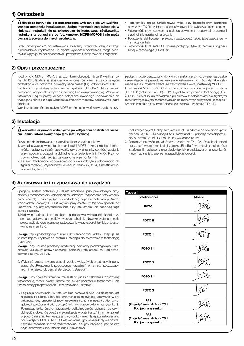
Specjalny system połączeń „BlueBus” umożliwia (przy prawidłowym przy-dzieleniu fotokomórkom odpowiednich adresów) rozpoznanie fotokomórek przez centralę i realizację (po ich zadziałaniu) odpowiednich funkcji. Nada-wanie adresu dotyczy TX i RX (wykonujemy mostek w ten sam sposób) po upewnieniu się, czyprzypadkiem innepary fotokomóreknieposiadają tegosamego adresu.1. Nadawanie adresu fotokomórkom na podstawie wymaganej funkcji – za pomocą ustawienia mostków według tabeli 1. Niewykorzystane mostkipozostawićdoewentualnegozastosowaniawprzyszłości,takjakprzedsta-wiono na rysunku 6.
Uwaga:Opis poszczególnych funkcji do każdego typu adresu znajduje sięw instrukcjach użytkowania centrali i interfejsu do sterowania z technologią„BlueBus”.Uwaga:Abyuniknąćproblemy interferencjipomiędzyposzczególnymiurzą-dzeniami„BlueBus”ustawićnadajnikiiodbiornikifotokomórektak,jakprzed-stawiono na rys. 2a i 2b.
2.Wykonaćprogramowaniecentraliwedługwskazówekznajdującychsięwparagrafie„Rozpoznaniepodłączonychurządzeń”winstrukcjiposzczegól-nychinterfejsówlubcentralsterujących„BlueBus”.
Uwaga:Gdynowafotokomórkamazastąpićjużzainstalowanąirozpoznanąfotokomórkę,mostkinależyustawićtak,jakdlapoprzedniejfotokomórkiinietrzebawtedyprzeprowadzać„Rozpoznawaniaurządzeń”.
3. Regulacja nastawienia:W fotokomórce nastawnejMOFOBdostępna jestregulacja położenia diody dla otrzymania perfekcyjnego ustawianiaw liniiwówczas, gdy sposób jej przymocowania na to nie pozwoli. Aby wyre-gulować położenia diody postąpić tak, jak przedstawiono na rysunku 8.Poluzować lekkośrubkę iprzestawićdelikatnieczęść ruchomą,poczymdokręcićśrubkę.Kierowaćsięsygnalizacjąwskaźnika„L”:immniejszajestprędkośćmigania,tymlepszejestwyśrodkowanie.Najlepszeustawieniawobuwersjach:MOFBiMOFOBjestwówczas,gdywskaźnikbłyskapowoli.Szybsze błyskanie można zaakceptować, ale gdy błyskanie jest bardzoszybkiewówczasliniafotoniedziałaprawidłowo.
Fotokomórka
FOTO
1) Ostrzeżenia
Niniejsza instrukcja jest przeznaczona wyłącznie dla wykwalifiko-wanego personelu instalującego. Żadne informacje znajdujące się w niniejszej instrukcji nie są skierowane do końcowego użytkownika. Instrukcja ta odnosi się do fotokomórek MOFB-MOFOB i nie może być zastosowana do innych produktów. Przed przystąpieniem do instalowania zalecamy przeczytać całą instrukcję!Nieprawidłoweużytkowanie lubbłędnewykonaniepodłączeniamogąnega-tywniewpłynąćnabezpieczeństwoiprawidłowefunkcjonowanieurządzenia.
• Fotokomórki mogą funkcjonować tylko przy bezpośrednim kontakcieoptycznymTX-RX;zabronionejestużytkowaniezwykorzystaniemlusterka.
•Fotokomórkiprzymocowaćnastałedopowierzchniodpowiedniopewnej istabilnej,nienarażonejnadrgania.
• Połączenia elektryczne i przewody zastosować takie, jakie zaleca się winstrukcji centrali.
•FotokomórkiMOFB-MOFOBmożnapodłączyćtylkodocentralizwyposa-żonejwtechnologię„BlueBUS”.
FotokomórkiMOFBiMOFOBsączujnikamiobecności (typuDwedługnor-myEN12453),któresąstosowanewautomatycebramisłużądowykryciaprzeszkódwosioptycznejpomiędzynadajnikiem(TX)iodbiornikiem(RX).Fotokomórki posiadają połączenie w systemie „BlueBus”, który ułatwiapołączeniawszystkichurządzeńzcentraląliniądwuprzewodową.Wszystkiefotokomórki są w prosty sposób połączone równolegle, odpowiednio dowymaganej funkcji, z odpowiednim ustawieniem mostków adresowych (patrz tabela 1).WersjęzfotokomórkamistałymiMOFBmożnastosowaćwewszystkichprzy-
padkach,gdziepłaszczyzny,doktórychzostanąprzymocowane,sąpłaskiei zezwalającenaprawidłowewzajemneustawienieTX iRX;gdy takieusta-wienieniejestmożliwezalecasięzastosowaniewersjinastawnejMOFOB.FotokomórkiMOFB iMOFOBmożna zastosować do nowej serii urządzeń„FT210B”(patrzrys2a i2b).FT210Bjesttourządzenieztechnologią„Blu-eBUS”,któresłużydorozwiązaniaproblemówzpołączeniamielektrycznymilistewkrawędziowychzamontowanychnaruchomychskrzydłach(szczegóło-wyopisznajdujesięwinstrukcjachużytkowaniaurządzeniaFT210B).
2) Opis i przeznaczenie
3) Instalacja
Wszystkie czynności wykonywać po odłączeniu centrali od zasila-nia i akumulatora awaryjnego (gdy jest używany).
Przystąpićdoinstalowaniapoweryfikacjiponiższychpunktów:1.wypadkuzastosowaniafotokomórkistałejMOFB, jakożenie jestfotoko-mórkąnastawną,należysprawdzić,czypowierzchnia,doktórejzostanieprzymocowana,pozwolinadokładnejejustawieniewlinii:TX-RX.Przymo-cowaćfotokomórkitak,jakwskazanonarysunku1ai1b.
2.Ustawić fotokomórki odpowiednio do funkcji odczytu i odpowiednio dotypuautomatyki.Wyregulowaćjewedługrysunku2,3i4,amostkiwyko-naćwedługtabeli1.
Jeślizażądanajestfunkcjafotokomórkijakurządzeniedootwierania(patrzrysunek2a,2b,3,4ipozycjeFA1iFA2wtabeli1),przyciąćmostekpomię-dzypunktami„A”naTXinaRX,jakwskazanonarys.
3.Podłączyć przewóddowłaściwych zaciskówTX i RX.Obie fotokomórkimusząbyćwzględemsiebieizacisku„BlueBus”wcentralisterującej(lubinterfejsieIB)połączonerównolegle(takjakprzedstawiononarysunku5).Niewymaganejestspełnieniezasadbiegunowości.
!
!
4) Adresowanie i rozpoznawanie urządzeń
Tabela 1
Mostki
FOTO II
FOTO 1
FOTO 1 II
FOTO 2
FOTO 2 II
FOTO 3
FA1(Przyciąć mostek A na TX i
RX, jak na rysunku.
FA2(Przyciąć mostek A na TX i
RX, jak na rysunku.

13
Fotokomórki nie wymagają specjalnych czynności konserwacyjnych. Co 6miesięcynależyzweryfikowaćichstan(czyniesąmokre,rdza,itp.),wyczyścićobudowę, szkiełka i ponownie wykonać czynności opisane w poprzednim
paragrafie.Fotokomórkizostałytakskonstruowane,żeczasfunkcjonowaniawnormalnychwarunkachprzewidujesięnaokresokoło10lat.Zalecasię,więcwykonanieczynnościkonserwacyjnychczęściej.
6) Konserwacja
7) Dane techniczne
Firma NiceS.p.A.zastrzegasobieprawowprowadzaniazmianparametrówtechnicznychwłasnychproduktówwjakiejkolwiekchwiliibezuprzedzenia,alegwa-rantującichfunkcjonalnośćiprzewidzianezastosowanie.Uwaga:wszystkieparametrytechniczneodnosząsiędotemperaturypracyrównej20°C. Typproduktu Czujnikobecnościdoautomatykibramidrzwi(typuDwedługnormyEN12453)złożonyzpary:nadajnik„TX”i odbiornik„RX”.Zastosowanatechnologia BezpośredniepołączenieoptyczneTXiRXzapomocąmodulowanejwiązkipodczerwieni.Zasilanie/wyjście Urządzeniemożnapodłączyćtylkodolinii„BlueBus”,odktórejotrzymujezasilanieidoktórejprzekazujesygnały wyjściowe.Pobór mocy 1 jednostka BlueBusZdolnośćwykrywania PrzedmiotymatowewosioptycznejTX-RXzwymiaramiwiększymiod50miprędkościmniejszejod1,6m/s.KąttransmisjiTX 20°+/-25%KątodbioruRX około20°RegulacjafotokomórkiMOFOB Około30°wkierunkach:poziomymipionowymZasięgużytkowy Do15mprzyodchyłceustawieniaTX-RX±5°(urządzeniemożezasygnalizowaćobecnośćprzeszkodyrównieżw przypadkubardzozłychwarunkówpogodowych).Zasięgmaksymalny Do30mprzyodchyłceustawieniaTX-RXmaksymalnie±5° (w optymalnych warunkach)Maksymalnadługośćprzewodów Do50mMożliwośćustaleniaadresów Do7czujnikówzfunkcjązabezpieczającą(przyzamykaniu)i2zfunkcjąsterowania(przyotwieraniu). Automatycznasynchronizacjazapobiegainterferencjipomiędzyczujnikami.Użytkowaniewatmosferzekwasowej, NiesłonejlubpotencjalniewybuchowejMontaż PionowonaścianieStopieńochronyobudowy IP55Temperatura eksploatacji 20 ÷55°CWymiary / waga do MOFB 69 x 78 h 25mm / 50g do MOFOB 69 x 78 h 37mm / 75g
6.1) LikwidacjaTak, jak w przypadku instalowania, po upływie okresu użytkowania tegoproduktuczynności demontażupowinnybyćwykonywaneprzezwykwalifi-kowany personel.Wyrób ten składa się z różnego rodzaju materiałów, niektóre z nichmogąbyćodzyskane, innemuszązostaćutylizowane,należyzasięgnąć informacjina temat systemów recyklingu lub utylizacji przewidywanych dla tego rodzaju produktu przez lokalne przepisy.
Uwaga:niektóreczęściurządzeniamogązawieraćskażającelubniebezpiecz-nesubstancje;jeślitrafiąonedośrodowiska,mogąwywołaćpoważneszkodydlasamegośrodowiskaorazdlazdrowialudzi.
Jakwskazujesymbolzrys.24zabraniasięwyrzucaćten produkt wraz z odpadkami domowymi. Należyprzeprowadzić „zbiórkę selektywną” na potrzebyutylizacji zgodnie ze sposobami przewidzianymi w miejscowych przepisach lub zwrócić produkt dosprzedawcy z chwilą zakupu nowego, równoważ-nego wyrobu.
Miejscoweprzepisymogąprzewidywaćciężkiesankcjewprzypadkusamo-wolnej utylizacji tego wyrobu.
11
PL
DIODA LWyłączona
3szybkiebłyskii1sekundowa przerwaPowolnebłyskanie
Szybszebłyskanie.Dioda szybko pulsuje.
Bardzo szybkie pulso-wanie.
Stałeświecenie.
StanFotokomórka nie jest zasilana lub jest uszkodzona.
Urządzenieniezostałorozpozna-neprzezcentralęsterującą.TXnadajeprawidłowo.RXodbieraprawidłowysygnał.RXodbieraprawidłowysygnał.RXodbierasłabysygnał.
RXodbierabardzosłabysygnał.
RXnieotrzymujeżadnegosygnału.
CzynnośćSprawdzić,czywzaciskachfotokomórkijestnapięcieokoło8-12Vps;gdynapięciejestprawidłoweprawdopodobniefotokomórkajestuszko-dzona.Powtórzyćproceduręrozpoznawania.Sprawdzić,czykażdaliniafotomainny adres. Prawidłowefunkcjonowanie.
Prawidłowefunkcjonowanie.Prawidłowefunkcjonowanie,alenależysprawdzićustawieniewliniiTX-RXiczyszybkisączyste.Nagranicyprawidłowegofunkcjonowania;należysprawdzićustawieniewliniiTX-RXiczyszybkisączyste.Sprawdzić,czyDIODAnaTXbłyskabardzopowoli.SprawdzićobecnośćprzeszkodypomiędzyTXiRX;sprawdzićustawieniewliniiTX-RX.
Tabela 2
Pofazieodczytusprawdzić,czyDIODAnafotokomórcepulsuje(naTXinaRX).Zweryfikowaćwedługtabeli2irodzajupulsacjidiody„L”stanfotokomórki.
5) Test odbiorczy i kontrola funkcjonowania
Uwaga:pododaniulubzastąpieniufotokomóreknależyponowniewykonaćtestodbiorczycałejautomatykiwedługwłaściwychinstrukcji.
W celu kontroli stanu fotokomórek i sprawdzenia, czy nie ma interferencji z innymi urządzeniami, przesunąć cylinder (o średnicy 5 cm i długości 30cm)przecinającośoptycznąnajpierwwpobliżuTX,późniejwpobliżuRXinastęp-niepośrodku isprawdzić,czyw tychprzypadkachurządzenieprzejdziezestanu aktywnego w stan alarmowy (tak jak przedstawiono na rysunku 9) i na odwrót,czywykonaczynnośćprzewidzianąwcentrali,np.:wruchuzamyka-
niaspowodujezmianękierunkuruchu.
PokontrolistanufotokomórekzgodnieznormąEN12445,wczęścizwiązanejz czujnikiem optycznym (typu D) ma być wykonana poprzez zastosowanierównoległościanu próbnego 700x300x200mm mającego 3 boki z jasną iodbijającą powierzchnią oraz 3 boki z ciemną i matową powierzchnią, jakprzedstawiononarysunku10iwedługwymagańznajdującychsięwrozdziale7wg.normyEN12445:2000(lubzałącznikAwprEN12445:2005).
L

14
Met het bijzondere communicatiesysteem “BlueBus” is het mogelijk door adressering van de speciale jumpers de fotocellen door de bedieningseenheid te laten herkennen en de juiste detectiefunctie toe te kennen. Deze adresse-ring dient zowel op TX als op RX uitgevoerd te worden waarbij u de jumpers op dezelfde manier moet positioneren. Ga hierbij na of er geen andere stellen fotocellen met hetzelfde adres zijn.1. Adresseer de fotocellen op basis van de gewenste functies door de jumpers
te positioneren volgens tabel 1. Leg de eventueel ongebruikte jumpers in het vakje terug zodat u ze eventueel later nog kunt gebruiken (zie afbeelding 6).
N.B.: Voor een gedetailleerde beschrijving van de verschillende functies die bij de verschillende soorten adressering worden uitgevoerd, verwijzen wij u naar de gebruikshandleiding voor bedieningseenheden en interfaces voorzien van de “BlueBus”-technologie.N.B.: Om problemen van interferentie tussen de verschillende “BlueBus”-inrichtingen te voorkomen, dient u de zenders en de ontvangers van de fotocellen, zo te plaatsen als op de afbeeldingen 2a en 2b te zien is.
2. Programmeer de inrichtingen op de besturingseenheid, zoals dat weer-gegeven is in de paragraaf “Herkennen van de aangesloten inrichtingen” van de gebruikshandleiding van de verschillende bedieningsinterfaces of bedieningseenheden “BlueBus”.
N.B.: Als de fotocel gebruikt wordt om een reeds bestaande fotocel te ver-vangen, dienen de jumpers net zo gepositioneerd te worden als dat het geval was bij de vervangen fotocel en is de herkenningsfase niet noodzakelijk.
3. Uitrichten: Bij de richtbare fotocel MOFOB is het mogelijk deze uit te richten zodat u een perfecte uitlijning kunt verkrijgen, ook wanneer bevestiging niet optimaal is. Voor het uitrichten handelt u zoals dat op afbeelding 8 is aan-gegeven. Draai de schroef wat losser en laat het beweegbare deel lang-zaam schommelen, draai de schroef daarna vast. Volg de signaleringen van het lampje “L”: hoe langzamer dat knippert des te beter is de uitlijning. Op beide uitvoeringen MOFB en MOFOB, is de uitlijning optimaal wanneer het lampje heel langzaam knippert, in ieder geval acceptabel wanneer het langzaam knippert, maar niet correct wanneer het lampje snel knippert.
Fotocel
FOTO
1) Aanbevelingen
Deze handleiding is uitsluitend bestemd voor technisch personeel dat voor de installatie gekwalificeerd is. Geen enkele informatie in dit dossier kan als interessant voor de eindgebruiker worden beschouwd! Deze handleiding heeft betrekking op de fotocellen MOFB-MOFOB en mag niet voor andere producten gebruikt worden.
Het is raadzaam deze aanwijzingen aandachtig door te lezen alvorens met het installeren te beginnen: oneigenlijk gebruik of een fout in de aansluiting zou de vei-ligheid of het correct functioneren van de inrichting nadelig kunnen beïnvloeden.
• De fotocel dient uitsluitend te functioneren via rechtstreekse interpolatie TX-RX; Het is verboden ze te gebruiken via reflectie.
• De fotocel dient blijvend op een vaste ondergrond zonder trillingen beves-tigd te worden.
• Voor de elektrische aansluitingen dient u de juiste geleidingen te gebruiken zoals dat in de handleidingen van de besturingseenheden staat aangegeven.
• De fotocellen MOFB-MOFOB kunnen alleen aangesloten worden op bestu-ringseenheden die met de “BlueBus”-technologie zijn uitgerust.
De fotocellen MOFB en MOFOB zijn obstakeldetectie-inrichtingen (type D volgens de norm EN 12453) die gebruikt kunnen worden in automatiseringen voor poorten en die obstakels op de optische as tussen zender (TX) en ont-vanger (RX) kunnen constateren. De fotocellen zijn uitgerust met het communicatiesysteem “BlueBus” waar-mee alle inrichtingen gemakkelijk met slechts twee draden aangesloten kunnen worden. De fotocellen worden eenvoudigweg allemaal parallel aange-sloten en de adresseringsjumpers worden op basis van de gewenste functie geselecteerd (zie tabel 1).
De niet-richtbare uitvoering MOFB kan toegepast worden in al die gevallen waarin de bevestigingsvlakken vlak zijn en waarop een correcte uitlijning TX-RX mogelijk is; waar een dergelijke uitlijning niet rechtstreeks mogelijk is, is het raadzaam de richtbare uitvoering MOFOB toe te passen.De fotocellen MOFB en MOFOB kunnen gebruikt worden samen met de nieuwe serie inrichtingen “FT210B” (zie afbeeldingen 2a en 2b). FT210B is een inrichting met de technologie “BlueBUS” waarmee het mogelijk is het probleem van de elektrische aansluitingen van de contactlijsten op de bewe-gende vleugels op te lossen (voor een gedetailleerde beschrijving verwijzen we u naar de gebruikershandeling van de inrichting FT210B).
2) Beschrijving en gebruiksbestemming
3) Installeren
Alle installatiewerkzaamheden dienen uitgevoerd te worden ter-wijl er geen stroom op de installatie staat; indien er een bufferbatterij aanwezig is, dient deze losgekoppeld te worden.
Voer nu de installatie uit en controleer de onderstaande punten:1. Bij toepassing van de vaste fotocel MOFB dient u na te gaan of de beves-
tigingsvlakken een correcte uitlijning TX-RX mogelijk maken, daar het niet mogelijk ze uit te richten. Bevestig de fotocellen zoals dat op afb. 1a en 1b is aangegeven.
2. Al naar gelang het type automatisering dient u de fotocellen op basis van hun detectiefuncties te plaatsen. Controleer op de afbeeldingen 2, 3 en 4,
de plaats en zet de jumpers volgens de tabel 1. Indien de fotocel als openingsinrichting moet werken (zie de afbeeldingen
2a,2b, 3, 4 en de adressen FA1 en FA2 in tabel 1), dient u het bruggetje tussen de punten “A” zowel op de TX als op de RX, zoals afb. 5 laat zien, te verkregen.
3. Sluit de elektriciteitskabel aan op de speciale klemmetjes zowel van de TX als van de RX. Uit een elektrisch oogpunt bezien dienen zowel TX als RX onderling parallel (zoals dat op afbeelding 5 is aangegeven) evenals op het klemmetje “BlueBus” van de interfaces of bedieningseenheden verbonden te worden. U behoeft geenszins op de polen te letten.
!
!
4) Adresseren en herkennen van de inrichtingen
Tabel 1
Jumpers
FOTO II
FOTO 1
FOTO 1 II
FOTO 2
FOTO 2 II
FOTO 3
FA1 (Verbreek het bruggetjeA op TX en RX, zoals dat op
afb. 5 te zien is)
FA2 (Verbreek het bruggetjeA op TX en RX, zoals dat op
afb. 5 te zien is)

15
LED “L”Uit
3 snelle knipperingen en een pauze van 1 seconde Zeer langzaam knipperen
Langzaam knipperenSnel knipperen
Zeer snel knipperen
Altijd aan
StatusDe fotocel wordt niet van stroom voorzien of is defect
Inrichting niet door de bedieningse-enheid herkendDe TX zendt naar behoren uit.De RX ontvangt een uitstekend signaalDe RX ontvangt een goed signaalDe RX ontvangt een slecht signaal
De RX ontvangt geen enkel signaal
De RX ontvangt geen enkel signaal
HandelingControleer of er op de klemmetjes van de fotocel een spanning van ongeveer 8-12 Vdc staat; als de spanning juist is, is de fotocel waar-schijnlijk defectVoer de procedure voor de inprenting van de besturingseenheid nogmaals uit. Controleer of alle stellen fotocellen een verschillend adres hebben Normale werking
Normale werkingNormale werking maar het is raadzaam te controleren of de TX-RX goed uitgelijnd zijn en de glaasjes goed schoon zijnOp het randje van een normale werking, maar het is noodzakelijk te controle-ren of de TX-RX goed uitgelijnd zijn en de glaasjes goed schoon zijnControleer of het ledlampje op de TX langzaam knippert. Controleer of er tussen TX en RX een obstakel is; Controleer of TX-RX op één lijn liggen.
Tabel 2
Controleer na het inprenten of het ledlampje op de fotocel knippert (zowel op TX als RX). Controleer in tabel 2 de status van de fotocel op grond van de manier waarop het ledlampje “L” knippert.
5) Eindtest en controle van de werking
Let op!: nadat u fotocellen erbij hebt gezet of vervangen hebt dient u de eindtest van de gehele automatisering opnieuw uit te voeren volgens wat in de desbetreffende handleidingen voor de installering is aangegeven.
Om te controleren of de fotocellen goed werken en vooral of er geen interfe-renties met andere inrichtingen zijn, voert u een cilinder met een diameter van 5 cm en een lengte van 30cm op de optische as, eerst dicht bij de TX, vervolgens dicht bij de RX en tenslotte in het midden van die twee (zoals dat op afbeelding 9 is aangegeven) en Ga dan na of de inrichting in alle gevallen in werking treedt
en van de actieve status op de alarmstatus overgaat, en omgekeerd; tenslotte controleert u of dat de voorziene reactie in de besturingseenheid oproept, bijvoorbeeld of de deur bij het sluiten de andere kant opgaat
Om te controleren of de fotocellen van de optische obstakeldetectie-inrichting (type D) volgens de norm EN 12445; deze controle dient uitgevoerd te worden volgens de eisen uit hoofdstuk 7 van de norm EN 12445:2000 (of bijlage A in prEN 12445:2005) met het testblok 700x300x200mm waarvan 3 vlakken mat zwart zijn en 3 glanzend wit of spiegelend).
L
7) Technische gegevens
Teneinde haar producten steeds meer te vervolmaken behoudt NICE S.p.a. zich het recht voor op elk gewenst moment en zonder voorbericht wijzigingen in haar produc-ten aan te brengen, waarbij functionaliteit en gebruiksdoel echter gehandhaafd blijven. N.B.: alle technische gegevens hebben betrekking op een temperatuur van 20°C. Type product Obstakeldetectie-inrichting voor automatiseringen van automatische poorten en deuren (type D volgens de norm EN 12453) bestaande uit een samenstel van zender “TX” en ontvanger “RX”Toegepaste technologie Rechtstreekse optische interpolatie TX-RX met gemoduleerde infrarood straal. Stroomvoorziening/uitgang De inrichting kan alleen op een “BlueBus”-net aangesloten worden waarover ze van elektrische stroom voorzien wordt en ze uitgangssignalen verzendt. Opgenomen vermogen 1 eenheid Blue busWaarnemingsvermogen Ondoorzichtige voorwerpen op de optische as tussen TX-RX die groter dan 50mm zijn en een snelheid van minder dan 1,6m/s hebben.Zendhoek TX 20° +/- 25%Ontvanghoek RX 20° circa Richtbaarheid van de fotocel MOFOB 30° circa op de horizontale en verticale asNuttig bereik Max. 15m met asafwijking TX-RX van maximaal ±5° (de inrichting kan een obstakel ook onder bijzonder slechte weersomstandigheden waarnemen )Maximaal bereik (onder optimale omstandigheden) Max. 30m met asafwijking TX-RX van maximaal ±5° Maximumlengte kabels Tot 50 m Mogelijkheid van adressering Max. 7 detectie-inrichtingen met beveiligingsfunctie en 2 met de bedieningsfunctie voor het openen. De automati sche synchronisering voorkomt interferentie tussen de verschillende detectie-inrichtingen Gebruik in zure, zoute of Neepotentieel explosieve atmosfeer Montage Verticaal aan de wandGrado di protezione contenitore IP55Bedrijfstemperatuur 20 ÷55°CAfmetingen / gewicht voor MOFB 69 x 78 h 25mm / 50g voor MOFOB 69 x 78 h 37mm / 75g
De fotocellen vereisen geen bijzonder onderhoud, maar tenminste eens per half jaar is het noodzakelijk een controle uit te voeren op de staat daarvan (aanwezigheid van vocht, roestvorming, etc.); bovendien moet dan de bui-tenkant van het kastje schoongemaakt worden en de eindtest zoals die in
de vorige paragraaf beschreven is, uitgevoerd worden. De fotocellen zijn ontworpen om onder normale omstandigheden tenminste 10 jaar te functi-oneren; het is raadzaam na afloop van die periode de onderhoudsfrequentie op te voeren.
6) Onderhoud
6.1) Afvalverwerking Wanneer de levensduur van dit product ten einde is, dienen, zoals dit ook bij de installatiewerkzaamheden het geval is, de ontmantelingswerkzaamheden door gekwalificeerd personeel uitgevoerd te worden. Dit product bestaat uit verschillende soorten materialen, waarvan sommige gerecycleerd kunnen worden. Win inlichtingen over de methoden van hergebruik of afvalverwerking in en houd u aan de plaatselijk van kracht zijnde voorschriften
Let op!: Sommige elektronische onderdelen zouden vervuilende of gevaar-lijke stoffen kunnen bevatten; als die in het milieu terecht zouden komen zouden ze schadelijke gevolgen voor het milieu en de menselijke gezondheid
kunnen veroorzaken.Zoals u kunt zien aan het symbool op afbeelding 24 is het verboden dit product met het gewone huisvuil weg te gooien Scheid uw afval voor verwerking op een manier zoals die in de plaatselijke regelgeving voorzien is; of lever het product bij uw leverancier in wanneer u een nieuw gelijksoortig product koopt.
De plaatselijke regelgeving kan in zware straffen voorzien in geval van illegale dumping van dit product.
11
NL

16
При адресации, используя специальные перемычки, система комму-никации “BlueBus” включает устройство управления для распозно-вания фотоэлементов и задает им правильную функцию обнаруже-ния. Адресация должна выполняться на TX и RX (перемычки должны быть расположены таким же образом). Убедитесь, что по одному и тому же адресу не находится другая пара фотоэлементов.
1. Адресуйте фотоэлементы, исходя из требуемой функции; при этом установите перемычки как показано в Таблице 1. Любые неисполь-зованные перемычки должны храниться в своем отделении, для возможности дальнешего использования (Рис.6).
Примечание: для получения подробного описания различных опера-ций, выполняемых для каждого видаадресации, обратитесь к руководству по эксплуатации устройств управления и командных интерфейсов с технологией “BlueBus”.Примечание (для FOTO 3): необязательно должны соблюдаться ограничения в позиионировании пары элементов (TX-RX), которые составляют каждую систему фотоэлементов; однако, если фотоэле-мент PHOTO 3 используется в соединении с флтоэлементом PHOTO II, должны соблюдаться позиции, изображенные на рис. 7.
2. Запрограммируйте устройства, используя устройство управления (см. параграф “Распознавание соединненых устройств” в инструк-ции по эксплуатации различных интерфейсов и устройств управле-ния “BlueBus”).
Примечание: Если фотоэлемент используется для замены уже суще-ствующего элемента, соединительные кабели должны быть подклю-чены точно так же. При этом можно пропустить фазу распознавания.
3. Регулирование координат заданного положения: можно настроить координаты регулируемого фотоэлемента MOFOB. Это позволит пользователю добиться более точного центрирования, даже если крепеж выполнен не очень хорошо. Чтобы отрегулировать центри-рование, следуйте Рис. 8. Ослабьте саморез и медленно поверните подвижную часть. Затем закрепите саморез. Следите за сигнала-ми на индикаторе “L”: чем медленнее мигают лампочки, тем лучше проходит центрирование.
Самое лучшее центрирование MOFB и MOFOB версии, когда индикатор начинает очень медленно; однако работа считается удовлетворительной, когда лампочки мигают просто медленно.
Центрирование считается неудовлетворительным, если индикатор быстро мигает.
1) Рекомендации
Данное руководство было специально составлено для ква-лифицированных установщиков автоматических систем. Инфор-мация, содержащаяся в руководстве, не предназначена для конечного пользователя!Руководство разработано для MOFB-MOFOB и не может быть использовано для другого продукта
Перед установкой внимательно прочтите инструкцию. Неправильное использование указанного продукта или ошибки в соединении могут повлиять на работу устройства и поставить под угрозу безопасность пользователей.
• Фотоэлемент должен работать исключительно через прямую интерполяцию TX-RX. Использование посредством отражения запрещено.
• Необходимо тщательно закрепить фотоэлемент на невибрирующей твердой поверхности.
• Для электрического соединения используйте провода, которые указа-ны в руководстве по эксплуатации раздел «устройства управления».
• Фотоэлементы MOFB-MOFOB могут быть подсоединены толь-ко к устройствам управления, которые используют технологию “BlueBus” .
Фотоэлементы MOFB и MOFOB, представляют собой детекторы присутствия препятствий (тип D в соответствии со стандартом EN 12453), которые могут быть использованы для автоматизации ворот. Они обнаруживают пряпятствия на оптической оси между передатчи-ком (TX) и приемником (RX).Фотоэлементы оснащены системой связи “BlueBus”.Данная система позволяет подсоединить устройства к блоку управ-ления при помощи двух проводов. Все фотоэлементы легко под-
соединяются параллельно, адресующие перемычки выбираются в соответствии требуемой функцией (см. Таблица 1).Нерегулируемую версию MOFB можно использовать только на исклю-чительно плоских поверхностях, для соблюдения правильного цен-трирования TX-RX. Производители рекомендуют использовать регу-лируемую версию MOFOB в случаях, когда невозможно напрямую провести центрирование.
2) Описание продукта и его применение
!
3) Установка
Начинайте установку только после того, как система было отключена от источника электропитания.Также отключите аккумуляторные батареи.
Начните процесс установки, с соблюдением следующих пунктов:1. Если во время использования закрепленных фотоэлементов MOFB
нельзя отрегулировать/настроить координаты заданного положе-ния, монтажники должны проверить, что поверхность, на которой будет закреплено устройство позволяет произвести правильное центрирование TX-RX. Закрепите фотоэлементы как показано на
рис. 1a и 1b.2. Позиционируйте фотоэлементы в зависимости от функций обнару-
жения и в зависимости от типа используемой автоматики. Проверь-те положение (см. рис.2, 3 и 4,) установите перемычки как указано в Таблице 1.
3. Подсоедините электрический кабель к фотоэлементам TX и RX. Соединение должно производится параллельно, как показано на Рис. 5, и должны быть подключены к интерфейсу “BlueBus” или устройствам управления. Полярность соблюдать необязательно.
!
4) Адресация и распознавание устройств
Fotocellula
FOTO
Таблица 1
Ponticelli
FOTO II
FOTO 1
FOTO 1 II
FOTO 2
FOTO 2 II
FOTO 3
FA1(tagliare ponticello A su TX e
RX, come da fig. 5)
FA2(tagliare ponticello A su TX e
RX, come da fig. 5)

17
RU
После окончания фазы распознования, проверьте, чтобы светодиод LED на фотоэлементе начал мигать (на TX и RX). Проверьте статус фото-элемент по таблице 2 в зависимости от типа загорания светодиода “L”.
5) Тестирование и проверка работы
Внимание: После того, как вы добавили или удалили фотоэлемент, необходимо заново провести инициализацию устройств (см. инструкцию).Для того, чтобы проверить фооэлементы и убедиться, что они не мешают работе других устройств, поместите цилиндр диаметром 5 см, длиной 30 см на оптическую ось сначала возле TX, затем возле
RX, в завершении – посередине; убедитесь, что во всех случаях про-исходит срабатывание фотоэлементов:устройство синхронизировано, переключается из рабочего режима в аварийный и наоборот; выполняет требуемый маневр, например, изменяет направление движения во время закрытия.
LED “L”Off (Выключено)
3 быстрые вспыш-ки и пауза 1 сек.Мигает очень медленноМигает медленноМигает быстро
Мигает оченьбыстроНе затухает
СтатусФотоэлемент либо отключен,либо неисправен
Устройство не было распознано устройством управленияTX регулярно подает сигнал RX принимает очень хороший сгналRX принмает четкийRX принимает слабый сигнал
RX принимает очень слабыйсигналRX не принимает вообще никако-го сигнала
ДействиеПроверьте, чтобы в терминалах фотоэлементов было напря-жение приблизительно 8-12 Vdc. Если напряжение правильное, фтоэлемент неисправен.Повторите процедуру инициализации на устройстве управления. Убедитесь, чтобы все пары фотоэлементов имели разные адресаНормальная работа
Нормальная работаНормальная работа. Однако будет лучше проверить центрирова-ние TX-RX и убедиться, что оптика чистаяНестабильная работа . Проверьте центровку TX-RX И убедитесь, что оптика чистая.Убедитесь, что светодиод на TX загорается медленно.Проверьте, чтобы между TX и RX не было помех. Проверьте центровку TX - RX - RX
Таблица 2
L
Фотоэлементы не требуют специального технического обслуживания. Однако необходимо проводить их проверку минимум раз в полгода с тем, чтобы оценить их состояние (присутствие влаги, окислене и т.д.). Внешнее покрытие и линзы должны быть чистыми; необходимо провести тестироване (описание дается в предыдущем параграфе).
Фотоэлементы были спроектированы таким образом, чтобы прорабо-тать в нормальных условиях минимум 10 лет. По прошествии данного периода следует увеличить частоту проведения техобслуживания указанных фотоэлементов.
6) Техническое обслуживание
7) Технические характеристики
Компания Nice S.p.a.в целях улучшения качества своего продукта оставляет за собой право в любое время модифицировать технические характеристики без предварительного уведомления. В любом случае производитель гарантирует их функциональное назначение соответ-ствие заданным характеристикам Тип продукта Устройство обнаружения для ворот и дверной автоматики (тип D всоответствии со стандартом EN dard 12453), ”Состоящее из передатчика“ТX” и приемника “RX”.Применяемая технология прямая оптическая интерполяция TX-RX при помощи модулированного инфрокрасного луча.Электропотребление Устройство может быть подсоединено к сети “BlueBus”, от нее оно получает электроэнергию и отправляет управляющие сигналы.Мощность 1 модуль “BlueBus”.Обнаруживающая возможность Непрозрачные объекты (>50 мм), размещенные на оптической оси между TX и RX, которые двигаются чуть медленнее 1.6м/с.угол передачи TX 20° +/- 25%угол приема RX Около 20° Регулируемость фотоэлемента MOFOB Регулируемость 30° на горизонтальной и вертикальной осях.Полезная мощность До 15м при максимальном отклонении TX-на ± 5° (устройство способно обнаружить и оповестить о наличии помехи даже при плохих погодных условиях).Максимальный радиус действия До 30м со смещением оси TX-RX макс. ± 5° (в оптимальных условиях)Максимальная длина кабеля До 50 м.Возможность адресации До 7 пар фотоэлементов с защитной функцией и 2 с функцией управления открытием.Использование в кислотной, Нет Солевой или взрывоопасной среде Монтаж Вертикально в навесном исполненииКласс защиты корпуса IP55Рабочая температура 20 ÷55°CРазмеры / вес MOFB 69 x 78 h 25мм / 50г MOFOB 69 x 78 h 37мм / 75пg
6.1) Утилизация Как монтаж, так и демонтаж изделия по окончании срока его службы должны проводиться квалифицированным персоналом.Настоящее изделие состоит из различных материалов, некоторые из которых могут перерабатываться, а другие подлежат утилизации. Более подробную информацию по переработке и утилизации различ-ных видов материалов можно получить в местных органах по охране окружающей среды.
Внимание: отдельные части изделия могут содержать вредные или опасные вещества, которые при ненадлежащей утилизации могут причинить ущерб окружающей среде или здоровью человека.Знаком, изображенным на рисунке 11, указывается на то, что данное
изделие нельзя утилизировать как бытовые отходы. Поэтому утилизируйте данное изделие отдельно от бытового мусора в соответствии с требованиями действующего местного законо-дательства;
или верните его в пункт продажи при покупке нового аналогичного изделия.
Действующие нормы по охране окружающей среды могут предусма-тривать серьезные санкции за нарушение правил утилизации данного изделия.
11

3
18
1a 1b
2a
2b
RX
RX
RX
TX
TX
TX
RX
TX
RX
TX
TX
RX
RX
TX
EN - SWING GATEIT - CANCELLO A BATTENTE FR - PORTAIL BATTANT DE - DREHTORES - PUERTA DE BATIENTE PL - BRAMA SKRZYD£OWANL - KANTELDEUR VOOR GARAGE RU - РАСПАШНЫЕ ВОРОТА
EN - SINGLE LEAF SLIDING GATEIT - CANCELLO SCORREVOLE AD ANTA SINGOLAFR - PORTAIL COULISSANT À UN SEUL VANTAIL DE - EINTEILIGES SCHIEBETORES - PUERTA DE CORREDERA DE UNA HOJAPL - BRAMA PRZESUWNA Z JEDNYM SKRZYD£EMNL - SCHUIFPOORT MET ENKELE VLEUGELRU - ВОРОТА РАЗДВИЖНЫЕ С ОДНОЙ СТВОРКОЙ
EN - SYNCHRONISED LEAFS SLIDING GATEIT - CANCELLO SCORREVOLE AD ANTE CONTRAPPOSTEFR - PORTAIL COULISSANT À VANTAUX OPPOSÉSDE - SCHIEBETOR MIT ENTGEGENGESETZT ANGEBRACHTEN TORFLÜGELNES - PUERTA DE CORREDERA DE HOJAS CONTRAPUESTASPL - BRAMA PRZESUWNA Z DWOMA PRZECIWLEØ°CYMI SKRZYD£AMINL - SCHUIFPOORT MET TEGENGESTELDE VLEUGELSRU - ВОРОТА РАЗДВИЖНЫЕ С ПРОТИВОПОСТАВЛЕННЫМИ СТВОРКАМИ
RX
TX
RX
TXRX
RX
RX
RX
RX
TX
TX
TX
TX
TX

19
5
7 8
9 10
4
6
L
EN - SECTIONAL DOORIT - GARAGE SEZIONALE FR - PORTE SECTIONNELLEDE - SEKTIONALTOR ES - GARAJE SECCIONAL PL - BRAMA GARAØOWA SEKCYJNANL - SECTIONAALGARAGEDEURRU - ГАРАЖНЫЕ СЕКЦИОННЫЕ
EN - UP & OVER GARAGE DOORS IT - GARAGE BASCULANTEFR - PORTE DE GARAGE BASCULANTEDE - GARAGENKIPPTORES - GARAJE BASCULANTEPL - GARAZ BRAMA UCHYLNANL - KANTELDEUR VOOR GARAGERU - ГАРАЖНЫЕ СРЕДНЕПОДВЕСНЫЕ

IST1
54R
01.4
854_
01-1
0-20
13
www.niceforyou.comNice SpAOderzo TV [email protected]
DICHIARAZIONE CE DI CONFORMITÀDichiarazione in accordo alle Direttive: 2004/108/CE (EMC)
Nota - Il contenuto di questa dichiarazione corrisponde a quanto dichiarato nell’ultima revisione disponibile, prima della stampa di questo manuale, del documento ufficiale depositato presso la sede di Nice Spa. Il presente testo è stato riadattato per motivi editoriali. Copia della dichiarazione originale può essere richiesta a Nice S.p.a. (TV) I.
Numero dichiarazione: 177/MOFB-MOFOB Revisione: 5 Lingua: IT
Nome produttore: NICE s.p.a.Indirizzo: Via Pezza Alta 13, Rustignè Industrial Zone, 31046 Oderzo (TV) ItaliaPersona autorizzata a costituire la documentazione tecnica: Nice s.p.a.Tipo di prodotto: Fotocellula da esternoModello / Tipo: MOFB, MOFOBAccessori: -
Il sottoscritto Mauro Sordini in qualità di Amministratore Delegato, dichiara sotto la propria responsabilità che il prodotto sopra indicato risulta conforme alle disposizioni imposte dalle seguenti direttive:
• DIRETTIVA 2004/108/CE DEL PARLAMENTO EUROPEO E DEL CONSIGLIO del 15 dicembre 2004 concernente il ravvicinamento delle legislazioni degli Stati membri relative alla compatibilità elettromagnetica e che abroga la direttiva 89/336/CEE, secondo le seguenti norme armonizzate:
EN 61000-6-2:2005, EN 61000-6-3:2007
Oderzo, 11 aprile 2014 Ing. Mauro Sordini (Amministratore Delegato)
CE DECLARATION OF CONFORMITYDeclaration in accordance with the following Directives: 2004/108/EC (EMC)
Note - The contents of this declaration correspond to declarations in the last revision of the official document deposited at the registered offices of Nice Spa and available before this manual was printed. The text herein has been re-edited for editorial purposes. A copy of the original declaration can be requested from Nice S.p.A. (TV) I.
Declaration number: 177/MOFB-MOFOB Revision: 5 Language: EN
Manufacturer’s Name: NICE s.p.a.Address: Via Pezza Alta 13, Rustignè Industrial Zone, 31046 Oderzo (TV) ItalyPerson authorized to compile the technical documentation: Nice s.p.a.Type of product: Outdoors photocellModel / Type: MOFB, MOFOBAccessories: -
The undersigned Mauro Sordini, as Managing Director, hereby declares under his own responsibility that the product identified above complies with the provisions of the following directives:
• DIRECTIVE 2004/108/EC OF THE EUROPEAN PARLIAMENT AND OF THE COUNCIL of 15 December 2004 on the approximation of the laws of the Member States relating to electromagnetic compatibility and repealing Directive 89/336/EEC, in accordance with following harmonised standards:
EN 61000-6-2:2005, EN 61000-6-3:2007
Oderzo, 11 April 2014 Mr. Mauro Sordini (Managing Director)