Embed Size (px)
Citation preview

PROPRIETARY RIGHTS STATEMENT This document contains information, which is proprietary to the MODURBAN Consortium. Neither this document nor the information contained herein shall be used, duplicated or communicated by any means to any third party,
in whole or in parts, except with prior written consent of the MODURBAN consortium.
MODURBAN FP6 Project: IP 516380
EC Contract n°: TIP4-CT-2005-516380
MODONBOARD SUBPROJECT
– DELIVERABLE REPORT –
Deliverable ID: D13 Deliverable Title: Demonstration on test track Responsible partner: ALSTOM
Contributors: WP2 Partners
MODURBAN Contract: TIP4-CT-2005-516380 Deliverable Report – WP2 – D13
Doc Name: Demonstration on test track Date: 02/03/2009 ID: DEL_MODONBOARD-D13_ALSTOM_WP2_090302_V10 Security: PUBLIC Revision: V10 Page 2/24
Document Information
Document Name: Demonstration on test track Document ID: D13 Revision: V10 Revision Date: 2009-03-02 Author: ALSTOM Security: PUBLIC
Approvals
Name Company Date Visa
Technical Management Committee
B. VON WULLERSTORFF G. POITRASSON-RIVIERE
D. DIMMER G. LEGOFF
L. LINDQVIST U. HENNING / A. PRICE
M. NOCK JP RICHARD / D. COINEAU
Y. AMSLER C. GOUTORBE
UNIFE ALSTOM THALES
ANSALDO STS BOMBARDIER
SIEMENS KNORR BREMSE
RATP UITP ALMA
03/03/09 OK
Coordinator B. VON WULLERSTORFF UNIFE 03/03/09 OK
Subproject Coordinator G. POITRASSON-RIVIERE ALSTOM 03/03/09 OK
Quality Manager
B. VON WULLERSTORFF C. GOUTORBE
UNIFE ALMA
03/03/09 OK
Documents history
Revision Date Modification Author
V0 12-09-08 Creation ALSTOM V1 26-09-08 Addings after meeting in Madrid 17/09/2008 ALSTOM V5 13-10-08 ALSTOM V7 20-10-08 Train interfaces update after integration test ALSTOM V8 22-10-08 On line runs description see chapter 3.4 ALSTOM V9 22-10-08 Upgrade of electrical interface (DIR and ATO) ALSTOM
V10 2-03-09 Review ALSTOM

MODURBAN Contract: TIP4-CT-2005-516380 Deliverable Report – WP2 – D13
Doc Name: Demonstration on test track Date: 02/03/2009 ID: DEL_MODONBOARD-D13_ALSTOM_WP2_090302_V10 Security: PUBLIC Revision: V10 Page 3/24
The scope of the document applies to: Metro and Light Rail
With specific adaptation(s)/recommendation(s) (1)
Metro systems
only With no
differenciation For metro For Light Rail
Light Rail only
X (1) – Put a [D] if these adaptations/recommendations are present in the document and a [L] if they will have to be detailed later.

MODURBAN Contract: TIP4-CT-2005-516380 Deliverable Report – WP2 – D13
Doc Name: Demonstration on test track Date: 02/03/2009 ID: DEL_MODONBOARD-D13_ALSTOM_WP2_090302_V10 Security: PUBLIC Revision: V10 Page 4/24
SECTION I – DELIVERABLE SUMMARY
D13 Intelligent driving prototyping
Deliverable ID , associated WP & Subproject
D13: Demonstration on test track MODONBOARD / WP2
Type of Deliverable Specification
Input / Starting stage Output / Final stage Lead partner(s)
Achievement to date (%) 100% Expected date of achievement
Type of exploitation Exploitation potential
Protection Not Relevant Protection date Not Relevant IP’s Partners, (type, identification, date) Pre-existing Know-How
Exploitation Rights
Associated Risk analysis Type, solution envisaged, action,
actors Actual Reduction
Before start
During task implementation

MODURBAN Contract: TIP4-CT-2005-516380 Deliverable Report – WP2 – D13
Doc Name: Demonstration on test track Date: 02/03/2009 ID: DEL_MODONBOARD-D13_ALSTOM_WP2_090302_V10 Security: PUBLIC Revision: V10 Page 5/24
D13: Intelligent driving prototyping Deliverable Abstract
Objective of WP2 is to think about an intelligent driving to tackle with the problem of time varying train parameters, ageing of train and discrepancies on train parameters of a whole fleet. Intelligent driving will modify the train control in case the command is no more able to reach asked ATC performances.
Objective of D13 is to specify the site test installation.
Associated Milestone (if relevant):

MODURBAN Contract: TIP4-CT-2005-516380 Deliverable Report – WP2 – D13
Doc Name: Demonstration on test track Date: 02/03/2009 ID: DEL_MODONBOARD-D13_ALSTOM_WP2_090302_V10 Security: PUBLIC Revision: V10 Page 6/24
TABLE OF CONTENT
1. INTRODUCTION ............................................................................................. 9
1.1. Document Organisation: ........................................................................................................................ 9
1.2. Objectives: ............................................................................................................................................... 9
2. TEST BENCH INSTALLATION..................................................................... 10
2.1. On track installation............................................................................................................................. 10 2.1.1. Beacons along the track (Herrera Oria/Barrio del pilar) .................................................................... 10 2.1.2. Beacon height installation.................................................................................................................. 10 2.1.3. Beacon lateral installation.................................................................................................................. 10
2.2. Antenna on board installation ............................................................................................................ 11 2.2.1. Lateral view of beacon installation .................................................................................................... 11 2.2.2. Detail of antenna bracket ................................................................................................................... 12 2.2.3. Top View of antenna on bogie. .......................................................................................................... 13
2.3. Electrical interface between Train and RPS ...................................................................................... 14 2.3.1. Connectors definition......................................................................................................................... 14 2.3.2. Connectors assignment ...................................................................................................................... 15 2.3.3. Manual /ID Mushroom Push Button .................................................................................................. 16
3. ON SITE TEST STRATEGY.......................................................................... 16
3.1. Introduction .......................................................................................................................................... 16
3.2. On board integration test ..................................................................................................................... 16 3.2.1. ID mechanical Installation ................................................................................................................ 16 3.2.2. Electrical installation/ static check..................................................................................................... 16 3.2.3. Dynamic check................................................................................................................................... 16
3.3. ATO Tuning .......................................................................................................................................... 17 3.3.1. Acceleration test................................................................................................................................. 17 3.3.2. Braking test ....................................................................................................................................... 18
3.4. Intelligent Driving test.......................................................................................................................... 19
4. TESTS RESULTS.......................................................................................... 19
4.1. On board integration test ..................................................................................................................... 19 4.1.1. ID mechanical Installation ................................................................................................................ 19 4.1.2. Electrical installation/ static check..................................................................................................... 20 4.1.3. Dynamic check................................................................................................................................... 20
4.2. ATO Tuning .......................................................................................................................................... 21 4.2.1. Acceleration test................................................................................................................................. 21 4.2.2. Braking test ....................................................................................................................................... 21
4.3. Intelligent Driving test.......................................................................................................................... 22

MODURBAN Contract: TIP4-CT-2005-516380 Deliverable Report – WP2 – D13
Doc Name: Demonstration on test track Date: 02/03/2009 ID: DEL_MODONBOARD-D13_ALSTOM_WP2_090302_V10 Security: PUBLIC Revision: V10 Page 7/24
5. DEMONSTRATION ....................................................................................... 23
5.1. Demonstration presentation................................................................................................................. 23
5.2. Demonstration HMI ............................................................................................................................. 23
5.3. Demonstration Scenario ....................................................................................................................... 24
5.4. Demonstration results........................................................................................................................... 24

MODURBAN Contract: TIP4-CT-2005-516380 Deliverable Report – WP2 – D13
Doc Name: Demonstration on test track Date: 02/03/2009 ID: DEL_MODONBOARD-D13_ALSTOM_WP2_090302_V10 Security: PUBLIC Revision: V10 Page 8/24
TABLE OF FIGURES figure 1. Beacon installation 9
figure 2. Beacon top view 9
figure 3. Antenna lateral view (dimensions are given in mm) 11
figure 4. Antenna bracket (dimensions are given in mm) 121
figure 5. Antenna Top View 13
figure 6. RPS connectors 14
figure 7. Acceleration test 17
figure 8. Braking test 18
figure 9. ID test run 19
figure 10. Fit example of a P6 bracking test. 21
figure 11. HMI presentation 223

MODURBAN Contract: TIP4-CT-2005-516380 Deliverable Report – WP2 – D13
Doc Name: Demonstration on test track Date: 02/03/2009 ID: DEL_MODONBOARD-D13_ALSTOM_WP2_090302_V10 Security: PUBLIC Revision: V10 Page 9/24
SECTION 2 – DELIVERABLE DETAILED DESCRIPTION
1. INTRODUCTION Objectives of this document are to define the on Metro-Madrid test of the intelligent driving function Prototype.
1.1. Document Organisation: This document is made of 5 clauses: 1 – Introduction This clause addresses the objectives of the document. 2 – Test bench installation This clause describes the installation on site. 3 – On site test strategy This clause describes the scenario for the different part of the project 4 – Test results This clause describes the result of the tests define in the section 3 5 – Demonstration This clause gives on overview of the demonstration.
1.2. Objectives: This document forms is part of the Work Package 2 “Onboard Intelligent Driving” which objectives are, according to the [DOW] to define and develop an intelligent automatic driving for the ATO in order to tackle with the problem of time varying train parameters, ageing of trains and discrepancies between trains in a fleet.
1.3. Glossary
AC Alternating Current ATO Automatic Train Operation DOT Direction Of Traffic HMI Human Machine Interface ID Intelligent Driving PID Proportional – Integral - Derivative PK Kilometric Point RPS Rapid Prototyping System
MODURBAN Contract: TIP4-CT-2005-516380 Deliverable Report – WP2 – D13
Doc Name: Demonstration on test track Date: 02/03/2009 ID: DEL_MODONBOARD-D13_ALSTOM_WP2_090302_V10 Security: PUBLIC Revision: V10 Page 10/24
2. Test bench installation
2.1. On track installation
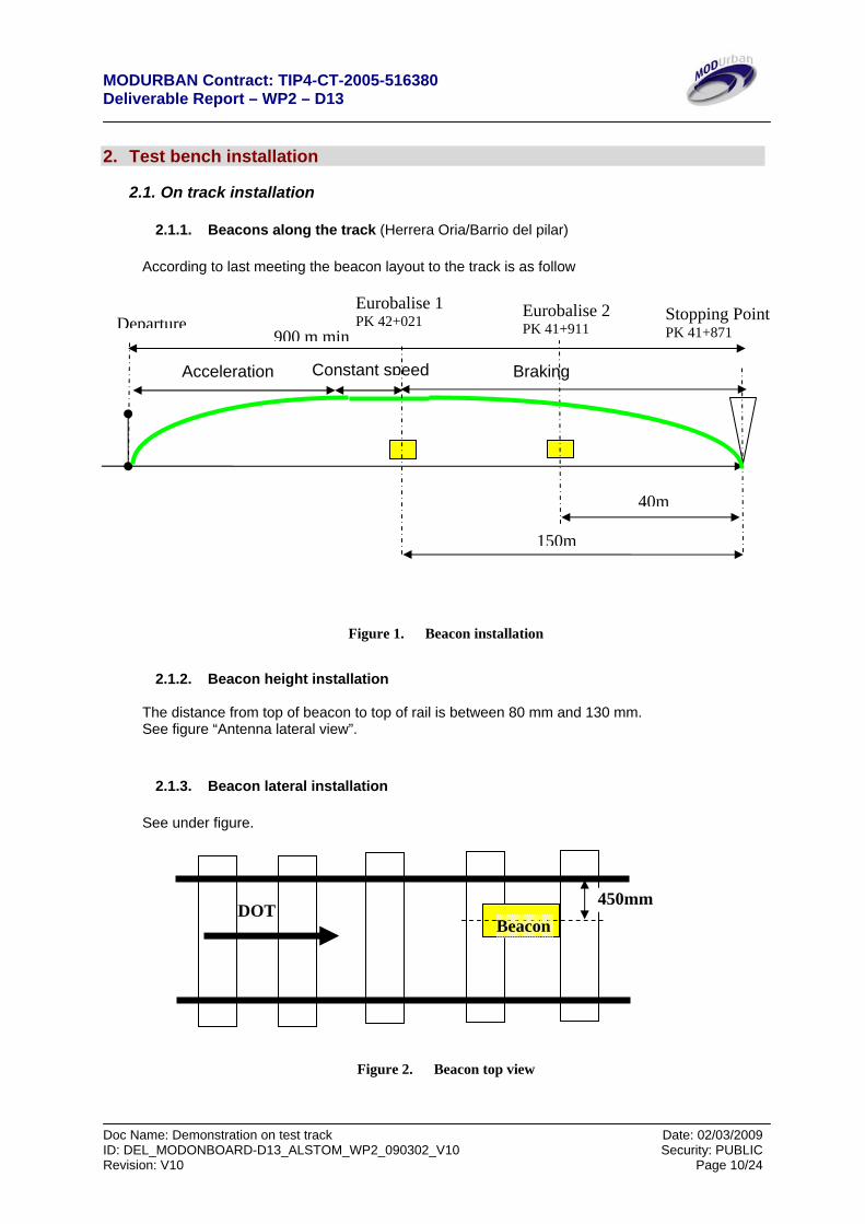
2.1.1. Beacons along the track (Herrera Oria/Barrio del pilar)
According to last meeting the beacon layout to the track is as follow
Figure 1. Beacon installation
2.1.2. Beacon height installation
The distance from top of beacon to top of rail is between 80 mm and 130 mm. See figure “Antenna lateral view”.
2.1.3. Beacon lateral installation
See under figure.
Figure 2. Beacon top view
DOT Beacon
450mm
900 m min
150m
Eurobalise 1 PK 42+021
Eurobalise 2 PK 41+911Departure Stopping Point
PK 41+871
40m
Acceleration Constant speed Braking

MODURBAN Contract: TIP4-CT-2005-516380 Deliverable Report – WP2 – D13
Doc Name: Demonstration on test track Date: 02/03/2009 ID: DEL_MODONBOARD-D13_ALSTOM_WP2_090302_V10 Security: PUBLIC Revision: V10 Page 11/24
2.2. Antenna on board installation
2.2.1. Lateral view of beacon installation
300
20
90
D=50
40
DIRECTION OF TRAVEL
Top of rail
Sleeper Sleeper Sleeper
285
181,5
55 160 80< X<130beacon
Top of beacon to top of rail is between 80 mm and 130mm
X
NOTE: All values are in millimeter.
Figure 3. Antenna lateral view (dimensions are given in mm)

MODURBAN Contract: TIP4-CT-2005-516380 Deliverable Report – WP2 – D13
Doc Name: Demonstration on test track Date: 02/03/2009 ID: DEL_MODONBOARD-D13_ALSTOM_WP2_090302_V10 Security: PUBLIC Revision: V10 Page 12/24
2.2.2. Detail of antenna bracket
300
20
220
D=50
40
220
44,5
111,1
155,6
D=9
D=11
70
100
100
NOTE: All values are in millimeter.
Figure 4. Antenna bracket (dimensions are given in mm)

MODURBAN Contract: TIP4-CT-2005-516380 Deliverable Report – WP2 – D13
Doc Name: Demonstration on test track Date: 02/03/2009 ID: DEL_MODONBOARD-D13_ALSTOM_WP2_090302_V10 Security: PUBLIC Revision: V10 Page 13/24
2.2.3. Top View of antenna on bogie.
450mm
RAIL
DIRECTION OF TRAFFIC
Figure 5. Antenna Top View

MODURBAN Contract: TIP4-CT-2005-516380 Deliverable Report – WP2 – D13
Doc Name: Demonstration on test track Date: 02/03/2009 ID: DEL_MODONBOARD-D13_ALSTOM_WP2_090302_V10 Security: PUBLIC Revision: V10 Page 14/24
2.3. Electrical interface between Train and RPS
2.3.1. Connectors definition
Connector’s type: 12 pins terminal
Figure 6. RPS connectors

MODURBAN Contract: TIP4-CT-2005-516380 Deliverable Report – WP2 – D13
Doc Name: Demonstration on test track Date: 02/03/2009 ID: DEL_MODONBOARD-D13_ALSTOM_WP2_090302_V10 Security: PUBLIC Revision: V10 Page 15/24
2.3.2. Connectors assignment
Plug 1 ODOMETER PIN WIRE DESCRIPTION Type REMARK Cable type
1 1 Signal 15V1 Input Odometre130 Twisted shielded pair 1 2 1 ref1 Input Odometer130 3 1&2 shielding Input Odometer130 4 2 Signal 15V2 Input Odometer130 Twisted shielded pair 2 5 2 ref2 Input Odometer130 6 3 signal 15V01 Input Odometer130 Twisted shielded pair 3 7 spare 8 spare 9 spare
10 spare 11 spare 12 spare
Plug 2
PIN WIRE DESCRIPTION Type REMARK Cable type 1 5 Output 0/-10V Output Electrical Brake Twisted shielded pair 5 2 5 shielding Output Electrical Brake 3 5 ref 0/10V Output Electrical Brake 4 spare 5 spare 6 spare 7 spare 8 spare 9 spare
10 spare 11 1 Contact ATO Output single wire 2 mm2 12 1 Contact ATO Output
No potential contact Open when ID drive single wire 2 mm2
Plug 3
PIN WIRE DESCRIPTION Type REMARK Cable type 1 1 spare 2 1 Relay 1 Output Pneumatic brake single wire 3 1 Relay 2 Output Pneumatic brake single wire 4 1 Relay 3 Output Pneumatic brake single wire 5 1 Relay 1 Output Traction single wire 6 1 Relay 2 Output Traction single wire 7 1 Relay 3 Output Traction single wire 8 1 Relay 4 Output Traction single wire 9 1 Battery 110V Input Power single wire 2 mm2
10 1 Battery 0V Input power single wire 2 mm2 11 1 Direction Output Traction Direction single wire 2 mm2 12 spare

MODURBAN Contract: TIP4-CT-2005-516380 Deliverable Report – WP2 – D13
Doc Name: Demonstration on test track Date: 02/03/2009 ID: DEL_MODONBOARD-D13_ALSTOM_WP2_090302_V10 Security: PUBLIC Revision: V10 Page 16/24
2.3.3. Manual /ID Mushroom Push Button
This Push button allows the ID to take the hand on the train. There are two separate circuits: One normally closes the other normally open.
Position Normally close circuit Normally open circuit ID mode Close Open
Manual mode Open Close ID battery supply Contact ATO
3. On site Test Strategy
3.1. Introduction The test strategy is divided in three phases:
• On board integration test • ATO Tuning • Intelligent driving tuning and test.
3.2. On board integration test
This integration can be done in depot. Mechanical and Electrical integration and static test (2 or 3 days)
3.2.1. ID mechanical Installation
• Antenna installation • ID cubicle • Cabling
3.2.2. Electrical installation/ static check • Power supply checking : 110 V Battery, AC and 24 V • Antenna test by moving a beacon under the Antenna • Traction and Braking interface check one by one • Odometer input check by slight moving • Excluder check.
3.2.3. Dynamic check
• Odometer check Running manually at 10 km/h and adjust diameter wheel parameter • Braking interface check : Test of the 7 level of braking effort • Motoring check: Test of the 4 level of motoring. • Antenna check: moving over one beacon put on the track.

MODURBAN Contract: TIP4-CT-2005-516380 Deliverable Report – WP2 – D13
Doc Name: Demonstration on test track Date: 02/03/2009 ID: DEL_MODONBOARD-D13_ALSTOM_WP2_090302_V10 Security: PUBLIC Revision: V10 Page 17/24
3.3. ATO Tuning
ATO tuning aim is to adjust the parameter of ATO to the response of the train. Two functions are to be tested. The following procedure is designed to reduce the length of the test track. The aim of this reduction is to try to allow this phase in depot test track. 3.3.1. Acceleration test At least 10 runs per target speed (15, 20 and 30 km/h) as follow:
Figure 7. Acceleration test
By target speed the following runs are done:
3.3.1.1. Constant Traction effort , Coasting, Braking
Constant Traction effort, Coasting at target speed, Braking phase The constant Traction effort asked is a run parameter: (Low speed, Serial, Parallel, Full) DIR is drive directly by ID excluder
Traction
DIR P1 P2 P3 P4 Coupling % 1 1 0 0 0 Low Speed 5 1 1 1 0 0 Serial 10 1 1 1 1 0 Parallel 50 1 1 1 1 1 Full 100
3.3.1.2. 2 levels Traction transition, Coasting , Braking
1 run: Traction Serial then Parallel, Coasting at target speed, braking 2 run: Traction Parallel then Serial, Coasting at target speed, braking
Target Speed
Acceleration
Time
ATO driving Manual
4s
MODURBAN Contract: TIP4-CT-2005-516380 Deliverable Report – WP2 – D13
Doc Name: Demonstration on test track Date: 02/03/2009 ID: DEL_MODONBOARD-D13_ALSTOM_WP2_090302_V10 Security: PUBLIC Revision: V10 Page 18/24
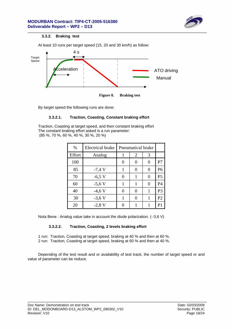
3.3.2. Braking test At least 10 runs per target speed (15, 20 and 30 km/h) as follow:
Figure 8. Braking test
By target speed the following runs are done:
3.3.2.1. Traction, Coasting, Constant braking effort
Traction, Coasting at target speed, and then constant braking effort The constant braking effort asked is a run parameter: (85 %, 70 %, 60 %, 40 %, 30 %, 20 %)
% Electrical brake Pneumatical brake
Effort Analog 1 2 3 100 0 0 0 P7 85 -7,4 V 1 0 0 P670 -6,5 V 0 1 0 P560 -5,6 V 1 1 0 P440 -4,6 V 0 0 1 P3 30 -3,6 V 1 0 1 P220 -2,8 V 0 1 1 P1
Nota Bene : Analog value take in account the diode polarization. (- 0,6 V)
3.3.2.2. Traction, Coasting, 2 levels braking effort
1 run: Traction, Coasting at target speed, braking at 40 % and then at 60 %. 2 run: Traction, Coasting at target speed, braking at 60 % and then at 40 %. Depending of the test result and or availability of test track, the number of target speed or and
value of parameter can be reduce.
Target Speed
Acceleration ATO driving Manual
4 s
MODURBAN Contract: TIP4-CT-2005-516380 Deliverable Report – WP2 – D13
Doc Name: Demonstration on test track Date: 02/03/2009 ID: DEL_MODONBOARD-D13_ALSTOM_WP2_090302_V10 Security: PUBLIC Revision: V10 Page 19/24
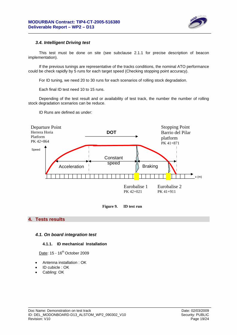
3.4. Intelligent Driving test
This test must be done on site (see subclause 2.1.1 for precise description of beacon
implementation). If the previous tunings are representative of the tracks conditions, the nominal ATO performance
could be check rapidly by 5 runs for each target speed (Checking stopping point accuracy). For ID tuning, we need 20 to 30 runs for each scenarios of rolling stock degradation. Each final ID test need 10 to 15 runs. Depending of the test result and or availability of test track, the number the number of rolling
stock degradation scenarios can be reduce. ID Runs are defined as under:
Figure 9. ID test run
4. Tests results
4.1. On board integration test
4.1.1. ID mechanical Installation
Date: 15 - 16th October 2009
• Antenna installation : OK • ID cubicle : OK • Cabling: OK
Speed
x (m)
Acceleration
Constant speed
Braking
Eurobalise 1 PK 42+021
Eurobalise 2 PK 41+911
Departure Point Herrera Horia Platform PK 42+864
Stopping Point Barrio del Pilar platform PK 41+871
DOT

MODURBAN Contract: TIP4-CT-2005-516380 Deliverable Report – WP2 – D13
Doc Name: Demonstration on test track Date: 02/03/2009 ID: DEL_MODONBOARD-D13_ALSTOM_WP2_090302_V10 Security: PUBLIC Revision: V10 Page 20/24
4.1.2. Electrical installation/ static check
→ Date: 15 - 16th October 2009
• Power supply checking : 110 V Battery, AC and 24 V: 0K • Antenna test by moving a beacon under the Antenna :OK • Traction and Braking interface check one by one: OK • Odometer input check by slight moving: OK • Excluder check : OK
4.1.3. Dynamic check
→ Date: 17- 29 - 30th October 2009
• Odometer check Running manually at 10 km/h and adjust diameter wheel parameter
Measured perimeter directly on the wheel: 2,57 m. Implementation of the above parameter in the software: speed compliant.
• Braking interface check : Test of the 7 level of braking effort
Changing in the command to send to the train: we have to send the both command (Electrical and Pneumatical) at the same time
Verified deceleration As the maximum deceleration is 1 m.s-² the effort is done in %:
% % Theoretical Effort Measured Effort
P7 100 100 P6 85 85 P5 70 75 P4 60 60 P3 40 40 P2 30 20 P1 20 N.A
We decide not to use the P1 level because of his smoothness not of interest for the
demonstration. The in order to obtain the parameter of the train, we compare the results of the different braking
tests with a simple model in the Laplace space ate
s−
+τ11
a delay τ constant time

MODURBAN Contract: TIP4-CT-2005-516380 Deliverable Report – WP2 – D13
Doc Name: Demonstration on test track Date: 02/03/2009 ID: DEL_MODONBOARD-D13_ALSTOM_WP2_090302_V10 Security: PUBLIC Revision: V10 Page 21/24
Figure 10. Fit example of a P6 bracking test.
• Motoring check: Test of the 4 level of motoring.
Problem with the train interface to motor the train. Problem solved by MetroMadrid
Level of motoring OK, driven by software or manually with the relays.
• Antenna check: moving over one beacon put on the track: OK. • Others:
The dynamic tests some changing in the cabling interface with the train occurred. Indeed when the ATO was on it was impossible to the driver to make an emergency brake was. Metro-Madrid managed to by pass the problem for the emergency braking.
The cabling of the ATO / Manual driving was also changed by MetroMadrid to allow us to drive automatically the train.
4.2. ATO Tuning
→ Date: 2 – 3 – 4 – 5 – 6 – 9th November 2009 4.2.1. Acceleration test
On the depot test track, the open loop is sufficient to reach the limit speed asked and coast we a
slight jerk. On the line, we decide to take advantage of the slope in order to approximate the behavior of an
operating metro. We tuned the motoring ATO to reach a speed around 20 km/h at the beginning of the slope and we command a coasting. So the train accelerates till the bottom of the slope and decelerates on the ramp. Once the train reaches the top of the ramp the tuning of the ATO allow it to reach the first Euro-balise around 20 to 21 km/h.
4.2.2. Braking test
• ATO testing
The first task was to verify if the ATO concept which command the braking phase is valid.
Five runs were dedicated to verify if the breaking phase is correctly triggered by the balises
and if the breaking distance fit with the demonstration needs. During those first tests the breaking

MODURBAN Contract: TIP4-CT-2005-516380 Deliverable Report – WP2 – D13
Doc Name: Demonstration on test track Date: 02/03/2009 ID: DEL_MODONBOARD-D13_ALSTOM_WP2_090302_V10 Security: PUBLIC Revision: V10 Page 22/24
distance, around 50 to 60 m, was too long. It didn’t allow a demonstration set of the ID capability because with a simulated degradation of 10 and 30 % of the braking capability we stop after the platform. The ATO tuning is to smooth
We used some runs to fine tune the ATO’s command laws discretization of the braking level and
finally obtained a minimal breaking distance around 25 m.
• PID tuning Then we use a pre-tune PID using the highest constant time drag from the braking level tests
and verify that we stop properly. With some minor retuned the minimal breaking distance obtained is around 30 m. We decide to keep this distance has a reference because it allows a good number of runs for the demonstration.
With those tests we can begin to calculate the parameters for the I.D. system.
N.B. During those tests we have pointed out that the parameters of the train are evolving along
the night. Despite of that they are quite repeatable during more or less 6 to 8 runs, a sufficient number of test to obtain some results.
4.3. Intelligent Driving test
→ Date: 23 – 25 – 28th November 2009 04 – 12 – 15th December 2009 Test of intelligent driving began by verifying the repeatability of a “nominal” run and if the
computed parameters of the train are correct and if the ID is able to absorb the evolution of the train parameters during a night test.
After the dynamic breaking test, we decide to set the nominal breaking distance after the second
Euro-balise at 30 m. In this case we can test simulated breaking losses without overrun the platform. During the first phase of our test, the nominal state we achieved a braking distance of
29,5 m ± 0,3 m Once it’s verified, 5 runs were necessary to verify the repeatability of the simulation of a 30 %
braking loss. In order to be faster during the test we forced the first value of the ID correction. It certainly has
saved us around 5 to 10 correction steps (25 to 50 runs). The others runs are made with the I.D. on. The second phase of the tests was to verify the repeatability of each step of correction for the
demonstration.

MODURBAN Contract: TIP4-CT-2005-516380 Deliverable Report – WP2 – D13
Doc Name: Demonstration on test track Date: 02/03/2009 ID: DEL_MODONBOARD-D13_ALSTOM_WP2_090302_V10 Security: PUBLIC Revision: V10 Page 23/24
5. Demonstration
5.1. Demonstration presentation
→ Date: 16th December 2009 The demonstration will take place in December 16th 2008 in Madrid between two stations of the
subway line 9. The starting point is Herrera Oria station (starting point) and the arrival Barrio del Pilar. The Demonstration consists in 10 runs. To demonstrate the intelligent driving capability we
choose to show a set of 5 runs, each one played twice. Each runs is triggered by an HMI that also display the results.
5.2. Demonstration HMI
The HMI is divided in four sections:
• Simulation settings (clear blue background, top left), • data saving (right top), • data displaying result (bottom left), • Alarms displaying (dark blue background, bottom right).
Simulation settings: contains 3 buttons: one to launch the simulation one to start the train and
the last to stop the simulation and qo the train. The run to be played is set by hand in a box. Data saving: a box to put the name of the saved file and a drawing button in order to verify the
data. Data displaying result: It’s trigged by the passage over the second Euro-balise. It contains a
graphical box with the theoretical braking phase of each demonstrated runs. It also indicates numerical values of the speed and the braking distance after the second Euro-balise.
Alarms displaying: Under or Over braking lighten in red if detected, ID lighten in Green if in action or Normal State lighten in green if the braking is normal.
Figure 11. HMI presentation

MODURBAN Contract: TIP4-CT-2005-516380 Deliverable Report – WP2 – D13
Doc Name: Demonstration on test track Date: 02/03/2009 ID: DEL_MODONBOARD-D13_ALSTOM_WP2_090302_V10 Security: PUBLIC Revision: V10 Page 24/24
5.3. Demonstration Scenario
The demonstration consists in a set of five run played twice.
• The first one simulates a 30 % loss of braking capability, • The 3 following runs will present a stage of I.D correction; • The fifth one will be the return to the nominal state (with ID on).
The train is automatically driven from Herrera Oria to Barrio del Pilar. The train reaches a
maximum speed around 50 km/h at the middle of the run and the ATO makes it reach the second Euro-balise at a speed around 20 to 21 km/h. It brakes and we put marks on the floor to show the ID effect. After that the train is driven manually to the starting station.
The sequence played will be: • 2 run 1: Braking loss of 30 % • 2 run 2: First step of ID • 2 run 3: Second step of ID • 2 run 4: Third step of ID • 2 run 5: last step of ID with return to nominal state.
Theoretical nominal breaking distances from the second balises : (Nominal State) NS = 29,6 m ± 0,4 m
• run 1: NS + 12,7 m ± 0,4 m • run 2: NS + 9,6 m ± 0,4 m • run 3: NS + 2 m ± 0,4 m • run 4: NS + 0,9 m ± 0,4 m • run 5: NS + 0 m ± 0,4 m <- Nominal state of the braking
The HMI only displays the breaking phase after the second Euro-balise to make it possible to
see the difference between the different braking distance.
5.4. Demonstration results
A nominal run is a run with a breaking distance accuracy comprises in the 40 cm of repeatability obtains during the tests.
• Run1
o First one: Not nominal NS + 35 m (cold brake) o Second one: Nominal NS + 12,4 m
• Run2
o First one: Nominal NS + 10 m o Second one: Nominal NS + 9,6 m
• Run3
o First one: Nominal NS + 2,2 m o Second one: Not Nominal NS + 4,5 m (No explanation)
• Run4 o First one: Nominal NS + 1,1 m o Second one: not played
• Run5
o First one Not Nominal NS - 1,5 m o Second one: not played