Embed Size (px)
Citation preview
PREPARED BY: MUNYANEZA Alphonse
HoD Information and Communication Technology
MUHABURA INTEGRATED POLYTECHNIC COLLEGE
NORTHERN PROVINCE
Website: www.mipc.ac.rw
E-mail: [email protected]
P.O. Box 26 Musanze – Rwanda
TEL: +250 788 687 033 “Accredited by WDA Resolutions of the BoD 1094/17 on 29 June 2017”
FACULTY: ENGINEERING TECHNOLOGY
DEPARTMENT: INFORMATION AND COMMUNICATION
TECHNOLOGY
YEAR OF STUDY: ONE
MODULE TITLE: FUNDAMENTALS OF NETWORKING

Table of Contents CHAPTER 1: COMPUTER NETWORK FUNDAMENTALS .................................................................................. 7
1.1 Computer Network Definition ............................................................................................................ 7
1.2 Properties of Computer Network ........................................................................................................ 8
1.2.1 Bandwidth and Latency ................................................................................................................ 8
1.2.2 Data Transmission ........................................................................................................................ 9
1.3 The common advantages and Disadvantage of Computer Networking ............................................ 11
1.3.1 The common advantages of computer network include: .......................................................... 11
1.3.2 The common disadvantages of computer networking include: ................................................ 12
1.4 Types of computer networks ............................................................................................................. 12
1.4.1.Types of computer network based the geographical area it spans ........................................... 12
1.4.2.LAN Categories ........................................................................................................................... 16
1.4.3.NETWORK/ LAN TOPOLOGY ....................................................................................................... 18
1.4.4 Internetwork (Internet, Intranet, Extranet) ............................................................................... 24
CHAPTER 2: NETWORK MODELS ........................................................................................................ 25
2.1 Computer network protocols ............................................................................................................. 25
2.2 OSI model .......................................................................................................................................... 30
2.2.1 Definition ................................................................................................................................... 30
2.3 TCP/IP model ..................................................................................................................................... 35
2.3.1 Introduction ............................................................................................................................... 35
2.4 Summary of network models ............................................................................................................ 37
CHAPTER 3: PLANNING AND CABLING NETWORKS ..................................................................... 38
3.1.Introduction to common networking devices .................................................................................. 38
3.2.NETWORK TRANSMISSION MEDIUM ................................................................................................ 43
3.2.1.GUIDED TRANSMISSION MEDIA ................................................................................................ 43
CHAPTER 4: IP ADDRESSING ............................................................................................................... 49
4.1.Understand the purpose of IP Addresses ........................................................................................ 49
4.2. IP version 4 (IPv4) structure ............................................................................................................ 49
4.3. IP Classes ......................................................................................................................................... 50
4.3.1 Subnet Masks ............................................................................................................................. 50
4.3.2.Private IP Addressing ................................................................................................................. 52
4.3.3.Reserved IP Addresses ............................................................................................................... 54
4.3.4.Introduction to Subnet a Network ............................................................................................. 54
4.4.Internet Protocol Version 6 (IPv6) .................................................................................................... 57
CHAPTER 5: CONFIGURING AND TESTING NETWORKS ............................................................... 58
5.1.IP address assignment ....................................................................................................................... 58
5.1.1.Static IP assignment ................................................................................................................... 58
5.1.2.Dynamic IP configuration ........................................................................................................... 61
5.1.3 INTERNET CONTROL MESSAGE PROTOCOL (ICMP) ................................................................... 65
5.1.4.Configuration of routers and access points ............................................................................... 66
CHAPTER 6: CONFIGURING CISCO DEVICES/ INTRODUCTION TO ROUTING AND PACKETS
FORWARDING ......................................................................................................................................... 76
6.1 The Cisco IOS ................................................................................................................................... 76
6.2 Introduction to routing and packet forwarding ................................................................................. 77

THE AIMS OF THE COURSE ARE TO:
Define a Computer Network
Understand how networks operate
Discuss the advantages of using a network.
Describe the different types of Networks.
Identify differences between a LAN & WAN
Identify a peer-to-peer network and a server-based network.
Determine which type of network is appropriate for a site.
Discuss communication over the network
Discuss about:
Application Layer Functionality and Protocols
OSI Transport Layer
OSI Network Layer
Addressing the Network-IPv4
Data Link Layer
OSI Physical Layer
Ethernet
o Overview of Ethernet
o Communicating through the LAN
Planning and Cabling Networks
Configuring and Testing your Network
Introduce Routing and Packet Forwarding
Learning outcomes:
This course will help a student to understand: Introduction to Computer Networks and Devices,
Structure of communication network (Topologies), Transmission media: magnetic media, twisted
ABSTRACT
This course will help the students to understand: The principles, standards and purposes of
computer networks , Structure of communication network (Topologies), different types of
transmission media: magnetic media, twisted pair, coaxial, fiber-optics, the OSI/ISO reference
model, network addressing and how to configure Cisco devices.

pair, coaxial, fiber-optics, the OSI/ISO reference model, network addressing and configuring Cisco
devices.
Learning and Teaching Strategy
Methods of delivery includes; use of face to face sessions in form of lectures, group discussions,
individual researches and Use of a computer lab.
Mode of assessment: • The assessment method is structured to include coursework and final examination.
Coursework consists of written assignments and tests.
• The marks to be earned by students are represented as follows: course work assessment is
60% and final examination is 40% then the total is 100%.
• The minimum mark required to pass is 50%, this includes course work and final examination.
READING LIST: 1. Data communications and networking by Behrouz A.Forouzan.
2. Discovery one: CCNA version 4.0 with networking concepts.
LIST OF ACRONYMS
ASCII: American Standard Code for Information Interchange
BGP: Border Gateway Protocol
BGP-4: Border Gateway Protocol version 4
CDDI: Copper Distribution Data Interface
CEF: Cisco Express Forwarding
CIDR: Classless Inter-domain Routing
CLI : Command-Line Interface
CLSC : Cisco LAN Switching Configuration
CPU : Central Processing Unit
CRC : Cyclic Redundancy Check (error)
CRF : Concentrator Relay Function
DB : Data Bus (connector)
DCE : Distributed Cisco Express Forwarding
DES : Data Encryption Standard
DHCP : Dynamic Host Control Protocol
DLC : Data-Link Connection Identifier
DNS: Domain Name Server
EGP: Exterior Gateway Protocol
EIGRP: Enhanced Interior Gateway Routing Protocol

FCC: Federal Communications Commission
FCS: Frame Check Sequence
FC: Feasible Condition (Routing)
FD: Feasible Distance (Routing
FDDI: Fiber Distributed Data Interface
FTP: File Transfer Protocol
GBIC: Gigabit Interface Converters
GEC: Gigabit Ethernet Channel
HDLC: High-Level Data Link Control
HDSL: High data-rate digital subscriber line
HSSI: High-Speed Serial Interface
HTTP: Hypertext Transfer Protocol
I/O: Input/Output
ICMP: Internet Control Message Protocol
IEEE: Institute of Electrical and Electronic Engineers
IGP: Interior Gateway Protocol
IGRP: Interior Gateway Routing Protocol
IOS: International Organization for Standardization
IP: Internet Protocol
IPv6: IP version 6
IS: Information Systems
ISO: Internetwork Operating System
ISP: Internet Service Provider
Kbps: kilobits per second (bandwidth)
LAN: Local Area Network
MAC: Media Access Control (OSI Layer 2 sub-layer)
MAN: Metropolitan-Area Network
NAS: Network Access Server
NAT: Network Address Translation
NetBIOS: Network Basic Input/Output System
NMS: Network Management System
NVRAM: Nonvolatile Random Access Memory
OSI: Open Systems Interconnection (Model
OSPF : Open Shortest Path First
PAT : Port Aggregation Protocol
PDU : Protocol Data Unit (i.e., a data packet)
POP : Point of Presence
PPP : Point-to-Point Protocol
RIF : Routing Information Field
RIP : Routing Information Protocol
RJ : Registered Jack (connector)
SMTP: Simple Mail Transfer Protocol
SQL: Structured Query Language
TCP : Transmission Control Protocol
TCP/IP: Transmission Control Protocol/Internet Protocol

TFTP: Trivial File Transfer Protocol
UDP : User Datagram Protocol
VLAN: Virtual Local Area Network
VLSM: Variable-Length Subnet Mask
VPN: Virtual Private Network
VTP: VLAN Trunking Protocol
WAN: Wide Area Network
WLAN: Wireless Local Area Network
WWW: World Wide Web
CHAPTER 1: COMPUTER NETWORK FUNDAMENTALS
Key Objective: To be able to explain principles, standards and purposes of computer networks.
1.1 Computer Network Definition
A computer network consists two or more computers connected together either (wirelessly or
using cables) usually for the purpose of communicating and sharing information or other
resources like printers, scanners, applications etc.
It can also be defined as a system of interconnected computers for the purpose of sharing data and
resources.
Computers on a network are called nodes. Nodes can include hosts such as personal computers,
phones, servers as well as networking hardware. Two devices are networked together when one
device is able to exchange information with the other device.
The computer can be connected to another in the two ways:
• Wired network: Computers are connected using cable media. Most commonly Ethernet
Cable, coaxial cable and optic fiber.

• Wireless network: Computers are connected using wireless media. Radio waves are used
in wireless mode.
1.2 Properties of Computer Network
An effective and efficient network must be able to meet a certain number of criteria. The most
important of these are:
• Easy Sharing of Resources: Computers are able to share various resources easily over a
network. Shared resources can be Internet, files, printer, storage and others.
• Performance: It is achieved by measuring the speed of data transmission with number of
network users, connectivity used and the software used. The commonly measured qualities
in the network performance are Bandwidth and Latency.
• Reliability: Network reliability is measured by the frequency of failure, the time it takes a
link to recover from a failure. It means that computer network provides assurance of the
delivery of data to the intended recipient.
• Scalability: The possibility of adding new computer without affecting the network
performance.
• Security: computer network must be secured for the benefit of the user and data protection.
The security is achieved by protecting data from unauthorized access.
1.2.1 Bandwidth and Latency
When data is sent over a computer network, it is broken up into small chunks called packets. Each
packet contains source and destination address information. Packets are sent across a network one
bit at a time.
Bandwidth: is the amount of data that can be transmitted in a fixed amount of time.
Bandwidth is measured in the number of bits that can be sent every second.
The following are examples of bandwidth measurements:
• b/s - bits per second
• kb/s - kilobits per second
• Mb/s - megabits per second
• Gb/s - gigabits per second
Latency is the time between requesting data and receiving data. More simply put, the time it takes
to establish a connection between your computer and the server hosting the website you requested.
The important thing to take away here is that latency is not speed. Data is delayed by network
devices and cable length. Network devices add latency when processing and forwarding data.
Latency = file size: data rate or bandwidth
Note that: ISPs (Internet service providers) charge the amount of bandwidth according to what
an organization can afford. Keep in mind that you get amount of bandwidth you have paid for.
1.2.2 Data Transmission
As earlier mentioned…the fundamental purpose of a communication system is the exchange of
data between two parties: - this is something that computer networks enable us achieve.
There are five components that make up a data communications system which are: the message,
sender, receiver, medium, and protocol.
Message: The message is the information (data) to be communicated. Popular forms of
information include text, numbers, pictures, audio, and video.
Sender: The sender is the device that sends the data message. It can be a computer,
workstation, telephone handset, video camera, and so on.
Receiver: The receiver is the device that receives the message. It can be a computer,
workstation, telephone handset, television, and so on.
Transmission medium: The physical path by which a message travels from sender to
receiver. Some examples of transmission media include twisted-pair wire, coaxial cable,
fiber-optic cable, and radio waves.
Protocol: A set of rules that govern data communications. It represents an agreement
between the communicating devices.
Without a protocol, two devices may be connected but not communicating, just as two people
speaking different languages may not understand each other.
The data that is transmitted over the network can flow using one of three transmission
modes: simplex, half-duplex and full-duplex.

a. Simplex mode: it is a single one-way transmission.
In a simplex transmission mode, the communication between sender and receiver occurs only in
one direction. That means only the sender can transmit the data, and receiver can only receive the
data. The receiver cannot transmit any information back to the sender.
Examples of simplex transmission: the signal that is sent from a TV station to your home TV and
Keyboard to monitor is also an example of simplex transmission mode.
b. Half-Duplex: data flows in one direction at a time.
In half-duplex, the channel of communications allows alternating transmission in two directions,
but not in both directions simultaneously. Example of Half-duplex is the Walkie-Talkies used by
the police.
c. Full-Duplex: data flows in both directions at the same time.
In a full duplex transmission mode, the communication between sender and receiver can occur
simultaneously. Sender and receiver both can transmit and receive simultaneously at the same
time.
A telephone conversation is an example of full-duplex communication. Both people can talk and
be heard at the same time.
Comparison:
Basis for
Comparison
Simplex Half Duplex Full Duplex

Direction of
Communication
Communication is
unidirectional.
Communication is
two-directional but,
one at a time.
Communication is
two directional and
done simultaneously.
Send/Receive
A sender can send
data but, cannot
receive.
A sender can send as
well as receive the
data but one at a
time.
A sender can send as
well as receive the
data simultaneously.
Performance
The half-duplex and
full duplex produces
better performance
than the Simplex.
The full duplex
mode
produces higher
performance than
half duplex.
Full duplex has better
performance as it
doubles the
utilization
of bandwidth.
Example. Keyboard and monitor Walkie-Talkies
Telephone
1.3 The common advantages and Disadvantage of Computer Networking
1.3.1 The common advantages of computer network include:
1. Enhanced communication and availability of information: It allows access to a vast amount
of useful information.
Example: Population data, newsletters, online businesses, contents, Applications.
2. Allow resource sharing: Fewer resources are needed when an organization uses a computer
network. Example: Only one Printer is needed instead of buying a printer for each office.
3. File sharing made easy: Computer network allows people to share files, which help to save
more time and effort.
Example: A teacher can share homework to all students through school network.
4. Improve storage capacity: Since you are going to share information, files and resources to
other people, you have to ensure that all data and content are properly stored in the system.

5. Cost efficiency: on computer network, you can share software license installed on the server
and can then be used by various workstations on the same network.
6. Security of information and resources: users cannot see other users' files unlike on stand-
alone machines.
7. Backup of data is easy as all the data is stored on the file server.
1.3.2 The common disadvantages of computer networking include:
1. Lack of independence: people rely on computer network and when the system is down,
people get stack. Most of organizations depend on the computer networks.
2. Security issues: huge number of people uses a computer network to get and share their
files and resources, a certain user’s security would be always at risk. Viruses can spread to
other computers throughout a computer network. There is a danger of hacking, particularly
with wide area networks. Security procedures are needed to prevent such abuse, Examples:
The use of Antivirus and firewall.
3. Lack of robustness/ strength: when the main server of computer network breaks down,
the entire system would become useless.
1.4 Types of computer networks
A computer network is classified by the following specific characteristics:
1. Size of the area covered
2. Number of users connected
3. Number and types of services available
4. Area of responsibility
1.4.1.Types of computer network based the geographical area it spans
In general, Most Computer networks are classified according to the distance between individual
computers that are attached to the network.
The classification includes the following:
• Personal Area Networks (PAN)
• Local Area Networks (LAN)
• Metropolitan Area Networks (MAN)
• Wide Area Networks (WAN)
• Global Area Networks (GAN)
A. Personal Area Network (PAN)
A personal area network (PAN) is a network that connects devices, such as mice, keyboards,
printers, Smartphone, and tablets within the range of an individual person. PAN has connectivity
range up to 10 meters.
PAN may include wireless computer keyboard and mouse, Bluetooth enabled headphones,
wireless printers and TV remotes. All of these devices are dedicated to a single host and are most
often connected with Bluetooth technology.
Bluetooth: is a wireless technology that enables devices to communicate over short distances. A
Bluetooth device can connect up to seven other Bluetooth devices.
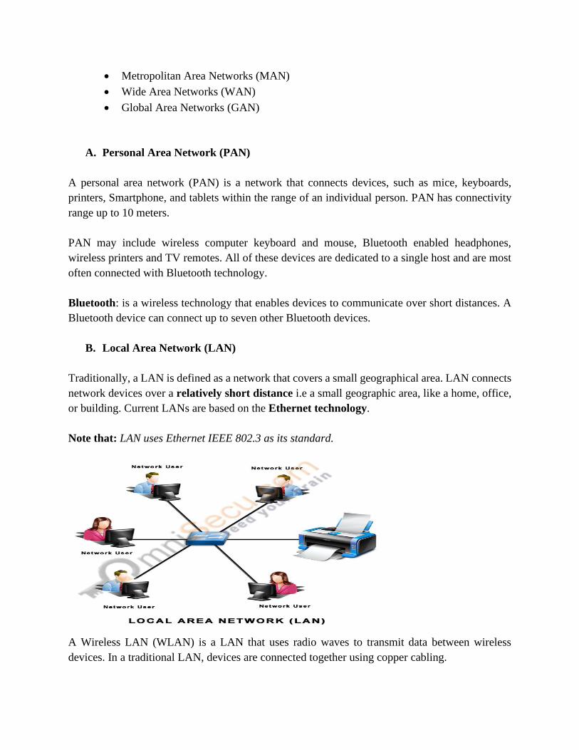
B. Local Area Network (LAN)
Traditionally, a LAN is defined as a network that covers a small geographical area. LAN connects
network devices over a relatively short distance i.e a small geographic area, like a home, office,
or building. Current LANs are based on the Ethernet technology.
Note that: LAN uses Ethernet IEEE 802.3 as its standard.
A Wireless LAN (WLAN) is a LAN that uses radio waves to transmit data between wireless
devices. In a traditional LAN, devices are connected together using copper cabling.
In some environments, installing copper cabling might not be practical, desirable, or even possible.
In these situations, wireless devices are used to transmit and receive data using radio waves. As
with LANs, on a WLAN, you can share resources, such as files, printers, and Internet access.
Note that: WLAN uses Ethernet IEEE 802.11 as its standard.
In 1985, the Institute of Electrical and Electronic Engineers (IEEE) – www.ieee.org , developed
a set of standards for LANs called IEEE 802 standards. It originally developed by Xerox in the
1970s.
IEEE is an organization composed of engineers, scientists, and students.
The IEEE is best known for developing standards for the computer and electronics industry. In
particular, the IEEE 802 standards for local-area networks are widely followed.
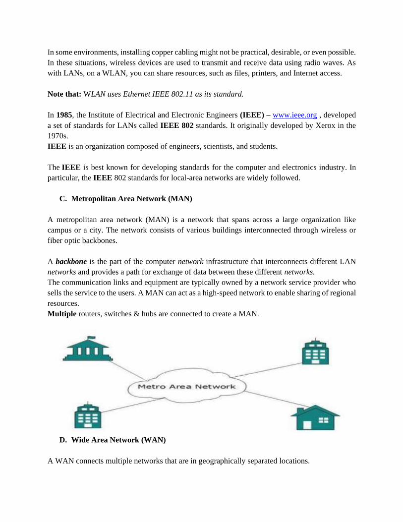
C. Metropolitan Area Network (MAN)
A metropolitan area network (MAN) is a network that spans across a large organization like
campus or a city. The network consists of various buildings interconnected through wireless or
fiber optic backbones.
A backbone is the part of the computer network infrastructure that interconnects different LAN
networks and provides a path for exchange of data between these different networks.
The communication links and equipment are typically owned by a network service provider who
sells the service to the users. A MAN can act as a high-speed network to enable sharing of regional
resources.
Multiple routers, switches & hubs are connected to create a MAN.
D. Wide Area Network (WAN)
A WAN connects multiple networks that are in geographically separated locations.
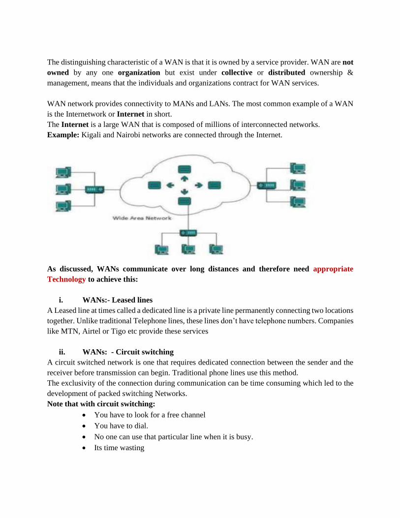
The distinguishing characteristic of a WAN is that it is owned by a service provider. WAN are not
owned by any one organization but exist under collective or distributed ownership &
management, means that the individuals and organizations contract for WAN services.
WAN network provides connectivity to MANs and LANs. The most common example of a WAN
is the Internetwork or Internet in short.
The Internet is a large WAN that is composed of millions of interconnected networks.
Example: Kigali and Nairobi networks are connected through the Internet.
As discussed, WANs communicate over long distances and therefore need appropriate
Technology to achieve this:
i. WANs:- Leased lines
A Leased line at times called a dedicated line is a private line permanently connecting two locations
together. Unlike traditional Telephone lines, these lines don’t have telephone numbers. Companies
like MTN, Airtel or Tigo etc provide these services
ii. WANs: - Circuit switching
A circuit switched network is one that requires dedicated connection between the sender and the
receiver before transmission can begin. Traditional phone lines use this method.
The exclusivity of the connection during communication can be time consuming which led to the
development of packed switching Networks.
Note that with circuit switching:
• You have to look for a free channel
• You have to dial.
• No one can use that particular line when it is busy.
• Its time wasting
iii. WANs: - Packet switching
Packet switching involves the splitting of data into packets which are then transmitted to the
receiving end (destination) over multiple channels.
At the receiving end, the data is then re-assembled to the original message and delivered. This is
made possible through a routing Algorithm.
The robust nature of this technology has made it dominant in modern telecommunication
Technology including the Internet.
E. Global Area Network (GAN)
GAN has no common definition but it is generally a model for supporting mobile
communications across an arbitrary number of wireless LANs, satellite coverage areas, etc.
1.4.2.LAN Categories
Two main categories of networks:
a) Client-Server Networks.
b) Peer-to-Peer networks.
These categories are based on the network design background or based on management
method rather than the geographical area it spans/ covers.
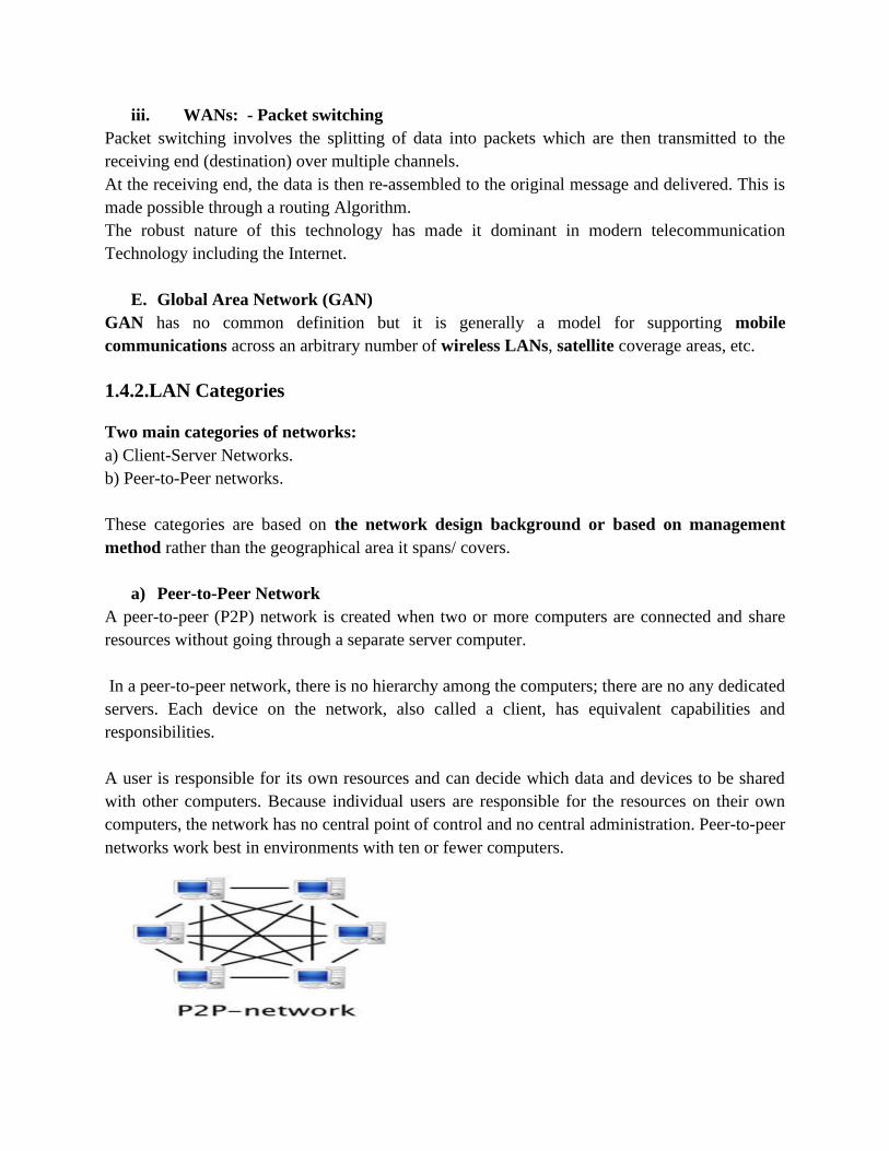
a) Peer-to-Peer Network
A peer-to-peer (P2P) network is created when two or more computers are connected and share
resources without going through a separate server computer.
In a peer-to-peer network, there is no hierarchy among the computers; there are no any dedicated
servers. Each device on the network, also called a client, has equivalent capabilities and
responsibilities.
A user is responsible for its own resources and can decide which data and devices to be shared
with other computers. Because individual users are responsible for the resources on their own
computers, the network has no central point of control and no central administration. Peer-to-peer
networks work best in environments with ten or fewer computers.
Advantages of peer to peer network are as follows:
➢ The main advantage of peer to peer network is that it is easier to set up
➢ In peer-to-peer networks all nodes are act as server as well as client therefore no need of
dedicated server.
➢ The peer to peer network is less expensive.
➢ Peer to peer network is easier to set up and use this means that you can spend less time in
the configuration and implementation of peer to peer network.
➢ It is not require for the peer to peer network to use the dedicated server computer. Any
computer on the network can function as both a network server and a user workstation.
Disadvantages of peer to peer network:
➢ A computer can be accessed anytime.
➢ Network security has to be applied to each computer separately.
➢ Backup has to be performed on each computer separately.
➢ No centralized server is available to manage and control the access of data.
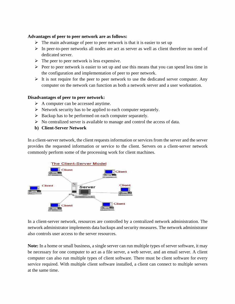
b) Client-Server Network
In a client-server network, the client requests information or services from the server and the server
provides the requested information or service to the client. Servers on a client-server network
commonly perform some of the processing work for client machines.
In a client-server network, resources are controlled by a centralized network administration. The
network administrator implements data backups and security measures. The network administrator
also controls user access to the server resources.
Note: In a home or small business, a single server can run multiple types of server software, it may
be necessary for one computer to act as a file server, a web server, and an email server. A client
computer can also run multiple types of client software. There must be client software for every
service required. With multiple client software installed, a client can connect to multiple servers
at the same time.
Advantages of Client-Server Network:
➢ Centralization of control: access, resources and integrity of the data are controlled by the
dedicated server so that a program or unauthorized client cannot damage the system.
➢ Scalability: You can increase the capacity of clients and servers separately. Any element
can be increased (or enhanced) at any time, you can add new nodes to the network (clients
or servers).
➢ Easy maintenance: distribute the roles and responsibilities to several standalone
computers, you can replace, repair, upgrade, or even move a server, while customers will
not be affected by that change (or minimally affect).
Disadvantage of Client Server Networks:
➢ There is a reliance on the central server, if it fails, no work can be done
➢ A network manager is required and this costs money
➢ The server costs money, as does the network operating system
➢ Servers are powerful, thus expensive;
➢ Lots of network traffic
1.4.3.NETWORK/ LAN TOPOLOGY
In networking, the term "topology" refers to the layout of connected devices on a network.
Network Topology is the schematic description of a network arrangement, connecting various
nodes through lines of connection.
The physical layout & configuration of computers, cables, nodes, and other peripherals on
a Network is generally referred to as the physical Network topology.
Network topology may also be logical and this generally refers to the protocols used on
the Network.
A better network can be built if you have the knowledge of these topologies and if you
know the difference between them.
a. BUS Topology
Bus topology is a network type in which every computer and network device is connected to
single cable. When it has exactly two endpoints, then it is called Linear Bus topology.
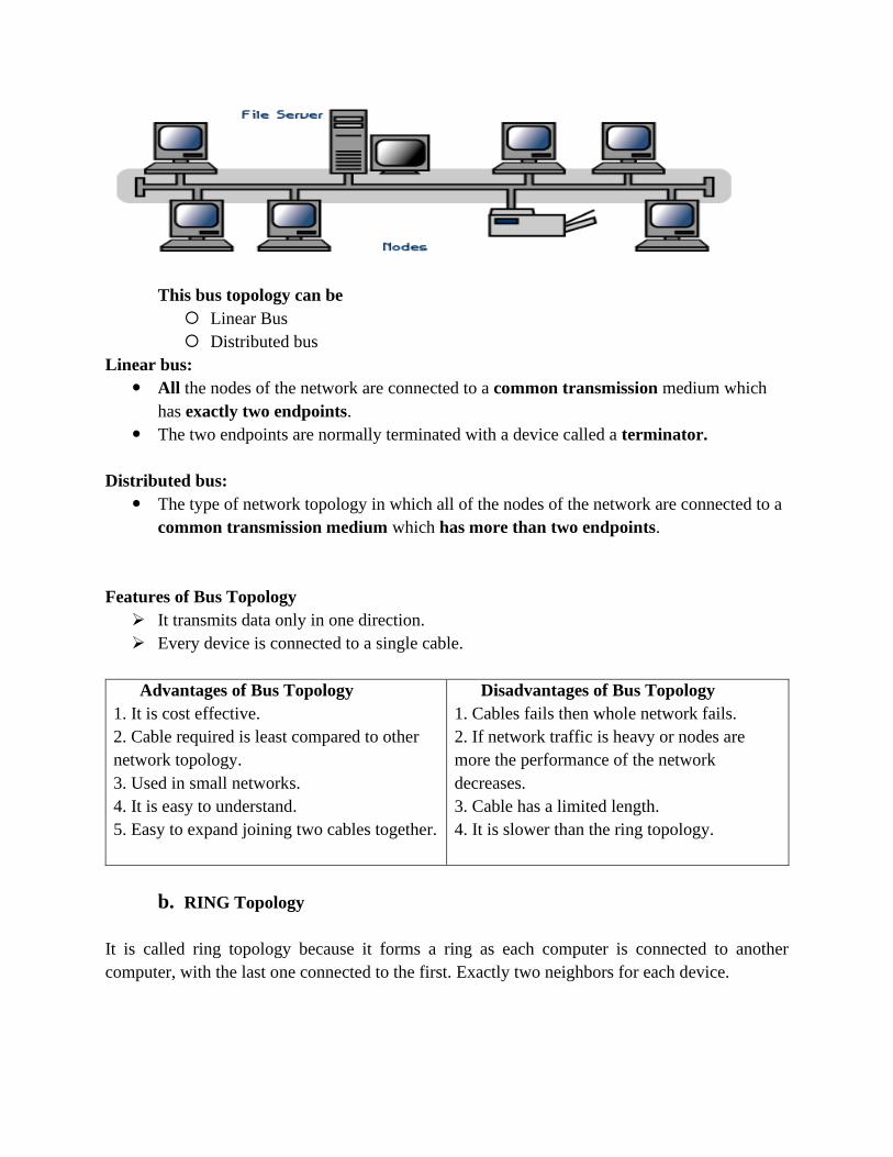
This bus topology can be
Linear Bus
Distributed bus
Linear bus:
All the nodes of the network are connected to a common transmission medium which
has exactly two endpoints.
The two endpoints are normally terminated with a device called a terminator.
Distributed bus:
The type of network topology in which all of the nodes of the network are connected to a
common transmission medium which has more than two endpoints.
Features of Bus Topology
➢ It transmits data only in one direction.
➢ Every device is connected to a single cable.
Advantages of Bus Topology
1. It is cost effective.
2. Cable required is least compared to other
network topology.
3. Used in small networks.
4. It is easy to understand.
5. Easy to expand joining two cables together.
Disadvantages of Bus Topology
1. Cables fails then whole network fails.
2. If network traffic is heavy or nodes are
more the performance of the network
decreases.
3. Cable has a limited length.
4. It is slower than the ring topology.
b. RING Topology
It is called ring topology because it forms a ring as each computer is connected to another
computer, with the last one connected to the first. Exactly two neighbors for each device.
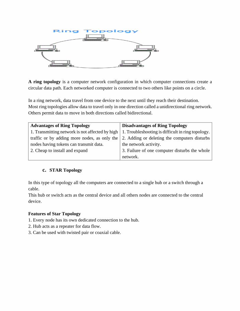
A ring topology is a computer network configuration in which computer connections create a
circular data path. Each networked computer is connected to two others like points on a circle.
In a ring network, data travel from one device to the next until they reach their destination.
Most ring topologies allow data to travel only in one direction called a unidirectional ring network.
Others permit data to move in both directions called bidirectional.
Advantages of Ring Topology
1. Transmitting network is not affected by high
traffic or by adding more nodes, as only the
nodes having tokens can transmit data.
2. Cheap to install and expand
Disadvantages of Ring Topology
1. Troubleshooting is difficult in ring topology.
2. Adding or deleting the computers disturbs
the network activity.
3. Failure of one computer disturbs the whole
network.
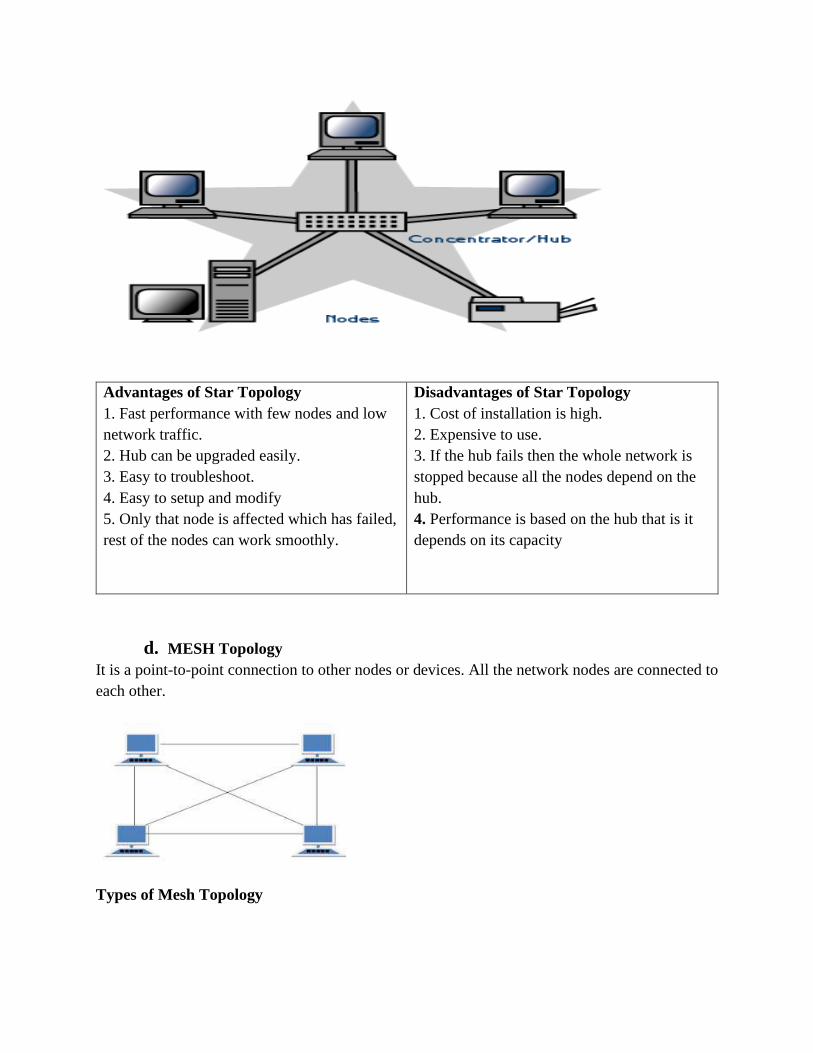
c. STAR Topology
In this type of topology all the computers are connected to a single hub or a switch through a
cable.
This hub or switch acts as the central device and all others nodes are connected to the central
device.
Features of Star Topology
1. Every node has its own dedicated connection to the hub.
2. Hub acts as a repeater for data flow.
3. Can be used with twisted pair or coaxial cable.
Advantages of Star Topology
1. Fast performance with few nodes and low
network traffic.
2. Hub can be upgraded easily.
3. Easy to troubleshoot.
4. Easy to setup and modify
5. Only that node is affected which has failed,
rest of the nodes can work smoothly.
Disadvantages of Star Topology
1. Cost of installation is high.
2. Expensive to use.
3. If the hub fails then the whole network is
stopped because all the nodes depend on the
hub.
4. Performance is based on the hub that is it
depends on its capacity
d. MESH Topology
It is a point-to-point connection to other nodes or devices. All the network nodes are connected to
each other.
Types of Mesh Topology
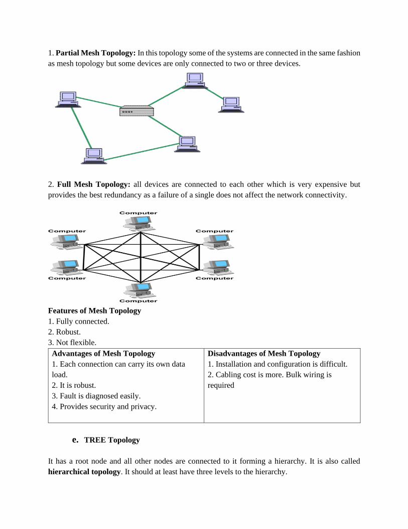
1. Partial Mesh Topology: In this topology some of the systems are connected in the same fashion
as mesh topology but some devices are only connected to two or three devices.
2. Full Mesh Topology: all devices are connected to each other which is very expensive but
provides the best redundancy as a failure of a single does not affect the network connectivity.
Features of Mesh Topology
1. Fully connected.
2. Robust.
3. Not flexible.
Advantages of Mesh Topology
1. Each connection can carry its own data
load.
2. It is robust.
3. Fault is diagnosed easily.
4. Provides security and privacy.
Disadvantages of Mesh Topology
1. Installation and configuration is difficult.
2. Cabling cost is more. Bulk wiring is
required
e. TREE Topology
It has a root node and all other nodes are connected to it forming a hierarchy. It is also called
hierarchical topology. It should at least have three levels to the hierarchy.
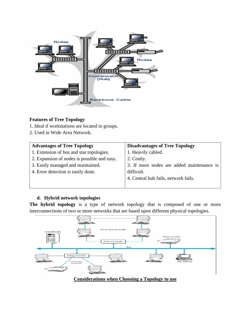
Features of Tree Topology
1. Ideal if workstations are located in groups.
2. Used in Wide Area Network.
Advantages of Tree Topology
1. Extension of bus and star topologies.
2. Expansion of nodes is possible and easy.
3. Easily managed and maintained.
4. Error detection is easily done.
Disadvantages of Tree Topology
1. Heavily cabled.
2. Costly.
3. If more nodes are added maintenance is
difficult.
4. Central hub fails, network fails.
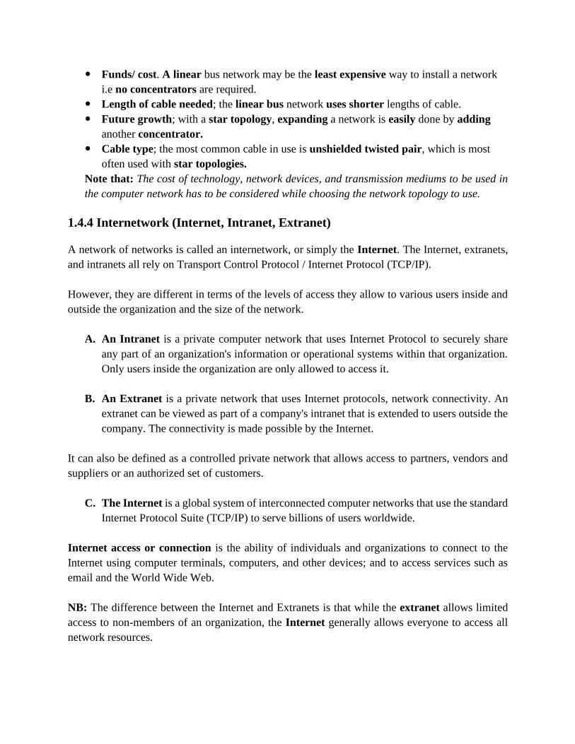
d. Hybrid network topologies
The hybrid topology is a type of network topology that is composed of one or more
interconnections of two or more networks that are based upon different physical topologies.
Considerations when Choosing a Topology to use
Funds/ cost. A linear bus network may be the least expensive way to install a network
i.e no concentrators are required.
Length of cable needed; the linear bus network uses shorter lengths of cable.
Future growth; with a star topology, expanding a network is easily done by adding
another concentrator.
Cable type; the most common cable in use is unshielded twisted pair, which is most
often used with star topologies.
Note that: The cost of technology, network devices, and transmission mediums to be used in
the computer network has to be considered while choosing the network topology to use.
1.4.4 Internetwork (Internet, Intranet, Extranet)
A network of networks is called an internetwork, or simply the Internet. The Internet, extranets,
and intranets all rely on Transport Control Protocol / Internet Protocol (TCP/IP).
However, they are different in terms of the levels of access they allow to various users inside and
outside the organization and the size of the network.
A. An Intranet is a private computer network that uses Internet Protocol to securely share
any part of an organization's information or operational systems within that organization.
Only users inside the organization are only allowed to access it.
B. An Extranet is a private network that uses Internet protocols, network connectivity. An
extranet can be viewed as part of a company's intranet that is extended to users outside the
company. The connectivity is made possible by the Internet.
It can also be defined as a controlled private network that allows access to partners, vendors and
suppliers or an authorized set of customers.
C. The Internet is a global system of interconnected computer networks that use the standard
Internet Protocol Suite (TCP/IP) to serve billions of users worldwide.
Internet access or connection is the ability of individuals and organizations to connect to the
Internet using computer terminals, computers, and other devices; and to access services such as
email and the World Wide Web.
NB: The difference between the Internet and Extranets is that while the extranet allows limited
access to non-members of an organization, the Internet generally allows everyone to access all
network resources.
CHAPTER 2: NETWORK MODELS
2.1 Computer network protocols
A network protocol defines or describes the rules and conventions for communication
between network devices. (A protocol is a set of rules that governs data communication or
is a set of rules governing the exchange or transmission of data between e-devices. A
protocol defines what is communicated, how it is communicated and when it is
communicated).
Network protocols include mechanisms for devices to identify and make connections with each
other, as well as formatting rules that specify how data is packaged into messages sent and
received.
➢ The key elements of a protocol are Syntax, Semantics and Timing.
1. Syntax: refers to the format of the data, meaning the order in which they are presented.
For example, a simple protocol might expect the first 8-bits of data to be the address of the sender,
the second 8-bits to be the address of the receiver and the rest of the stream to be the message
itself.
2. Semantics: refers to the meaning of each section of bits. How a particular pattern to
interpret and what action to be taken based on the interpretation.
For example, an address identifies the route to be take or the final destination of the message.
3. Timing: refers to two characteristics: when data should be sent and how fast they can be
sent.
For example, if a sender produces data at 100Mbps but the receiver can process data at only 1Mbps,
the transmission will overload the receiver and data will be largely lost.
Network protocols are grouped such that each one relies on the protocols that underlie it,
sometimes referred to as a protocol stack.
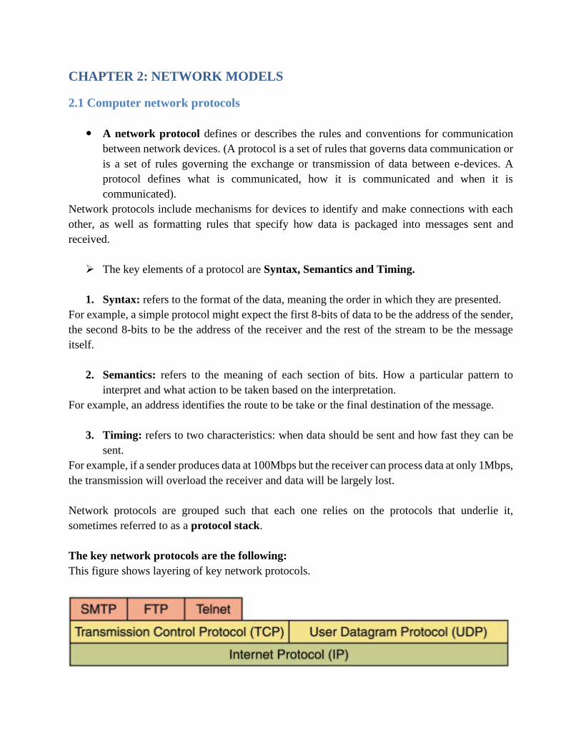
The key network protocols are the following:
This figure shows layering of key network protocols.
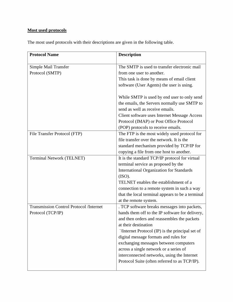
Most used protocols
The most used protocols with their descriptions are given in the following table.
Protocol Name
Description
Simple Mail Transfer
Protocol (SMTP)
The SMTP is used to transfer electronic mail
from one user to another.
This task is done by means of email client
software (User Agents) the user is using.
While SMTP is used by end user to only send
the emails, the Servers normally use SMTP to
send as well as receive emails.
Client software uses Internet Message Access
Protocol (IMAP) or Post Office Protocol
(POP) protocols to receive emails.
File Transfer Protocol (FTP)
The FTP is the most widely used protocol for
file transfer over the network. It is the
standard mechanism provided by TCP/IP for
copying a file from one host to another.
Terminal Network (TELNET)
It is the standard TCP/IP protocol for virtual
terminal service as proposed by the
International Organization for Standards
(ISO).
TELNET enables the establishment of a
connection to a remote system in such a way
that the local terminal appears to be a terminal
at the remote system.
Transmission Control Protocol /Internet
Protocol (TCP/IP)
. TCP software breaks messages into packets,
hands them off to the IP software for delivery,
and then orders and reassembles the packets
at their destination
Internet Protocol (IP) is the principal set of
digital message formats and rules for
exchanging messages between computers
across a single network or a series of
interconnected networks, using the Internet
Protocol Suite (often referred to as TCP/IP).
. TCP/IP is the language a computer uses to
access the Internet.
It consists of a suite of protocols designed to
establish a network of networks to provide a
host with access to the Internet.
TCP/IP can also be used as a communication
Protocol in a private network (an intranet or an
extranet).
User Datagram Protocol (UDP)
It is an alternative to TCP. The main
difference is that TCP is highly reliable, at the
cost of decreased performance, while UDP is
less reliable, but generally faster.
Post Office Protocol version 3 (POP3) POP3 is a standard mail protocol used to
receive emails from a remote server to a local
Email client.
POP3 allows you to download email
messages on your local computer and read
them even when you are offline.
Note that, when you use POP3 to connect to
your email account, messages are downloaded
locally and removed from the email server.
By default, the POP3 protocol works on two
ports:
Port 110 - this is the default POP3 non -
encrypted port.
Port 995 - this is the port you need to use if
you want to connect using POP3 securely.
Internet Message Access Protocol (IMAP) IMAP is a mail protocol used for accessing
email on a remote web server from a local
client.
IMAP and POP3 are the two most commonly
used Internet mail protocols for retrieving
emails.
Both protocols are supported by all modern
email clients and web servers.

➢ While the POP3 protocol assumes that
an email is being accessed only from
one application, IMAP allows
simultaneous access by multiple
clients. This is why IMAP is more
suitable for the user if he/she is going
to access his/her email from different
locations or if his/her messages are
managed by multiple users.
By default, the IMAP protocol works on two
ports:
Port 143 - this is the default IMAP non-
encrypted port.
Port 993 - this is the port someone needs to use
if he/she wants to connect using IMAP
securely.
Dynamic Host Configuration Protocol
(DHCP)
DHCP is a protocol that automatically provides
an Internet Protocol (IP) host with its IP
address and other related configuration
information such as the subnet mask and
default gateway.
Hypertext Transfer Protocol (HTTP)
The HTTP is a protocol used mainly to access
data on the World Wide Web.
HTTP functions as a combination of FTP and
SMTP.
Hypertext Transfer Protocol Secure (HTTPS) HTTPS is the secure version of HTTP, the
protocol over which data is sent between your
browser and the website that you are connected
to. It means that all communications between
your browser and the website are encoded.
HTTPS is often used to protect highly
confidential online communications like
online banking and online shopping order
forms.
Web browsers such as Internet Explorer,
Firefox and Chrome also display a padlock
icon in the address bar to visually indicate that
a HTTPS connection is in effect.
Secure Shell (SSH)
The SSH protocol is a method for securing
remote login from one computer to another.
It is a secure alternative to the non-protected
login protocols (such as telnet, rlogin) and
insecure file transfer methods (such as FTP).
Routing Protocols
There are two types of dynamic routing
protocols: Interior Gateway Protocols (IGP)
and External Gateway Protocols (EGP).
IGPs are used to exchange routing information
within an autonomous system (AS), which is
a collection of routing domains under the same
administrative control the same routing
domain.
An EGP, on the other hand, is used to exchange
routing information between different ASs.
Network Address Translation (NAT)
The advantage of using private IP addresses is
that it allows an organization to use private
addressing in a network, and use the Internet
at the same time, by implementing Network
Address Translation (NAT).
Address Resolution Protocol (ARP) ARP is a communication protocol used to
discover the link layer address such as MAC
address, associated with a given internet layer
address such as an IPv4 address.
Routing Information Protocol (RIP) RIP prevents routing loops by implementing a
limit on the number of hops allowed in a path
from source to destination.
In computer networking, a hop is one portion
of the path between source and destination.
Eg: packets pass through bridges, routers and
gateways and each time packets are passed to
the next network device, a hop occurs.
Some of the other most used protocols . Network Basic Input/output System
(NetBIOS)
NetBIOS Extended User Interface
(NetBEUI)
Domain Name System (DNS)
Internet Control Message Protocol (ICMP)
to notify sender of the event.
Internet Message Access Protocol version 4
(IMAP4)

➢ Definition of standard
Standards provide guidelines to manufacturers, vendors, government agencies, and other service
providers in guaranteeing national and international interoperability of data and
telecommunications technology and processes.
With Ethernet technologies, different types of standards have been so far used in networks.
2.2 OSI model
2.2.1 Definition
Open System Interconnect (OSI) is an open standard for all communication systems. OSI model
is established by International Standard Organization (ISO).
It is a general-purpose model for discussing or describing how computers communicate with one
another over a network. Its seven layered approach to data transmission divides the many
operations up into specific related groups of actions at each layer.
Data flow in OSI layers

In the OSI model, data flows down the transmit layers, over the physical link, and then up through
the receive layers.
The transmitting computer software gives the data to be transmitted to the applications layer, where
it is processed and passed from layer to layer down the stack with each layer performing its
designated functions. The data is then transmitted over the physical layer of the network until the
destination computer or another device receives it. At this point the data is passed up through the
layers again, each layer performing its assigned operations until the data is used by the receiving
computer’s software.
The roles of OSI model layers are:

PDU (Protocol Data Unit): identifies the format of data in the first 4 layers.
➢ As the data flows down through the layers in the hierarchy, each layer adds some extra
information to the data in the form of headers or tailors.
This process of wrapping data with headers and tailors is called encapsulation.
A. The Application Layer
The application layer enables the user, whether human or software, to access the network.
It provides user interfaces and support for services such as domain name service (DNS), file
transfer protocol (FTP), hypertext transfer protocol (HTTP), Internet message access protocol
(IMAP), post office protocol (POP), simple mail transfer protocol (SMTP), Telenet, and terminal
emulation.
Devices used in this layer are Gateways, Firewalls, and all end devices like PC’s, Phones, and
Servers.
B. The Presentation Layer
It presents data to the Application layer and is responsible for data translation and code formatting.
The presentation layer is concerned with the syntax and semantics of the information exchanged
between two systems.
Specific responsibilities of the presentation layer include the following: Translation,
Encryption and Compression
Devices which operate at this layer are Gateways, Firewalls and PC’s.
C. The Session Layer
The Session layer is responsible for setting up, managing, and then destroying down sessions
between Presentation layer entities. This layer also provides dialogue control between devices, or
nodes.
It coordinates communication between systems and serves to organize their communication by
offering three different modes: simplex, half duplex, and full duplex.
Specific responsibilities of the session layer include the following:
*Dialog control *Synchronization
The devices used at this layer are Gateways, Firewalls, and PC’s.
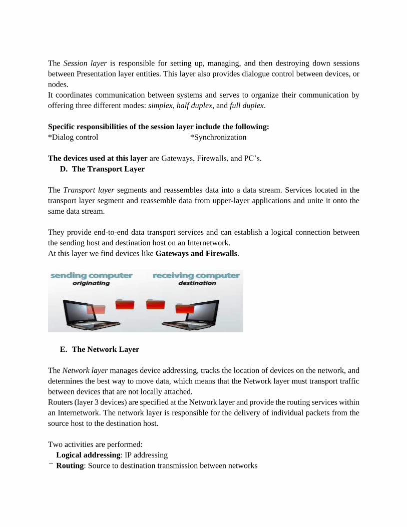
D. The Transport Layer
The Transport layer segments and reassembles data into a data stream. Services located in the
transport layer segment and reassemble data from upper-layer applications and unite it onto the
same data stream.
They provide end-to-end data transport services and can establish a logical connection between
the sending host and destination host on an Internetwork.
At this layer we find devices like Gateways and Firewalls.
E. The Network Layer
The Network layer manages device addressing, tracks the location of devices on the network, and
determines the best way to move data, which means that the Network layer must transport traffic
between devices that are not locally attached.
Routers (layer 3 devices) are specified at the Network layer and provide the routing services within
an Internetwork. The network layer is responsible for the delivery of individual packets from the
source host to the destination host.
Two activities are performed:
Logical addressing: IP addressing
Routing: Source to destination transmission between networks
F. The Data Link Layer
The Data Link layer formats the message into pieces; each called a data frame, and adds a
customized header containing the hardware destination and source address.
This added information forms a sort of capsule that surrounds the original message.
To allow a host to send packets to individual hosts on a local network as well as transmit packets
between routers, the Data Link layer uses hardware addressing.
Switches and bridges work at the Data Link layer and filter the network using hardware (MAC)
addresses.
G. The Physical Layer
Finally arriving at the bottom, we find that the Physical layer does two things: It sends bits and
receives bits.
Bits come only in values of 1 or 0. The Physical layer communicates directly with the various
types of actual communication media.
The Physical layer specifies the electrical, mechanical, procedural, and functional requirements
for activating, maintaining, and deactivating a physical link between end systems.
Devices like Hubs, Repeaters, Cables, and Fibers operate at this layer.
Notice that the following network devices operate on all seven layers of the OSI model:
▪ Network management stations (NMSs)
▪ Web and application servers
▪ Gateways (not default gateways)
▪ Network hosts
Advantages of using the OSI layered model
They include, but are not limited to the following:
1. It divides the network communication process into smaller and simpler components, for
aiding component development, design, and troubleshooting.
2. It allows multiple-vendor development through standardization of network components.
3. It encourages industry standardization by defining what functions occur at each layer of
the model.
4. It allows various types of network hardware and software to communicate.

5. It prevents changes in one layer from affecting other layers, so it does not affect hardware
or software development.
2.3 TCP/IP model
2.3.1 Introduction
The TCP/IP protocol suite was developed prior to the OSI model. Therefore, the layers in the
TCP/IP protocol suite do not exactly match those in the OSI model.
TCP/IP model is the combination of TCP as well as IP models. This model ensures that data
received is same as the data sent, and the data bytes are received in sequence.
This model mainly defines how data should be sent (by sender) and received (by receiver). Most
common examples of applications using this model include the email, media streaming, or World
Wide Web (WWW).
TCP/IP model comprises 4 layers that are as follows:
1. Application Layer

It groups the functions of OSI Application, Presentation and Session Layers. Application layer is
present on top of the Transport layer.
It includes protocols like:
➢ The Hypertext Transfer Protocol (HTTP) is used to transfer files that make up the Web
pages of the World Wide Web.
➢ The File Transfer Protocol (FTP) is used for interactive file transfer.
➢ The Simple Mail Transfer Protocol (SMTP) is used for the transfer of mail messages and
attachments.
➢ Telnet, a terminal emulation protocol, is used for logging on remotely to network hosts.
2. Transport layer
The Transport layer (also known as the Host-to-Host Transport layer) is responsible for providing
the Application layer with session and datagram communication services. The core protocols of
the Transport layer are Transmission Control Protocol (TCP) and the User Datagram Protocol
(UDP).
• TCP provides a one-to-one, connection-oriented, reliable communications service. TCP is
responsible for the establishment of a TCP connection, the sequencing and
acknowledgment of packets sent, and the recovery of packets lost during transmission.
• UDP provides a one-to-one or one-to-many, connectionless, unreliable communications
service. UDP is used when the amount of data to be transferred is small (such as the data
that would fit into a single packet).
The Transport layer encompasses the responsibilities of the OSI Transport layer and some of the
responsibilities of the OSI Session layer.
3. Internet layer
The Internet layer is responsible for addressing, packaging, and routing functions. The core
protocols of the Internet layer are IP, ARP, ICMP, and IGMP.
• The Internet Protocol (IP) is a routable protocol responsible for IP addressing, routing, and
the fragmentation and reassembly of packets.
• The Address Resolution Protocol (ARP) is responsible for the resolution of the Internet
layer address to the Network Interface layer address such as a hardware address.
• The Internet Control Message Protocol (ICMP) is responsible for providing diagnostic
functions and reporting errors due to the unsuccessful delivery of IP packets.
• The Internet Group Management Protocol (IGMP) is responsible for the management of
IP multicast groups.
The Internet layer is analogous to the Network layer of the OSI model.
4. Network Access Layer
This layer basically controls hardware devices and media that make up the network. Its tasks
include routing of data, sending it over the network, verifying the data format, and converting the
signs from analog to the digital format. TCP/IP can be used to connect differing network types.
These include LAN technologies such as Ethernet and Token Ring and WAN technologies.
The Network Interface layer encompasses the Data Link and Physical layers of the OSI model.
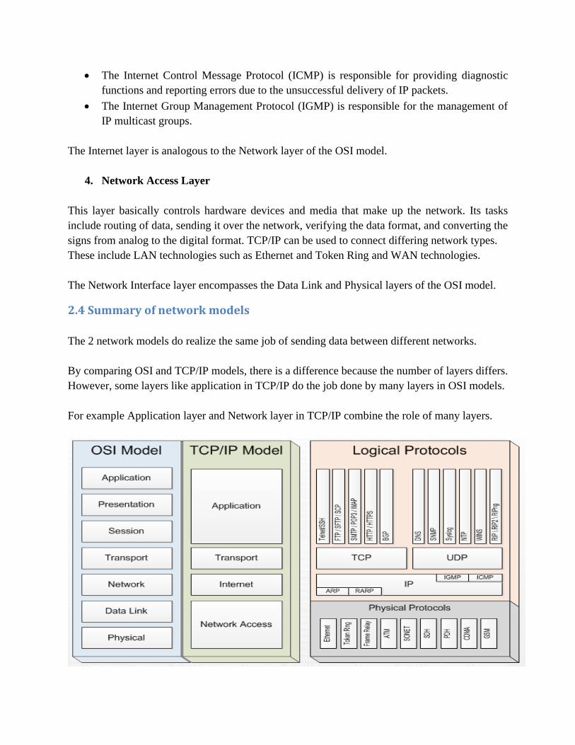
2.4 Summary of network models
The 2 network models do realize the same job of sending data between different networks.
By comparing OSI and TCP/IP models, there is a difference because the number of layers differs.
However, some layers like application in TCP/IP do the job done by many layers in OSI models.
For example Application layer and Network layer in TCP/IP combine the role of many layers.

Comparison: OSI vs. TCP/IP models
CHAPTER 3: PLANNING AND CABLING NETWORKS
3.1.Introduction to common networking devices

Computer networking devices are known by different names such as networking devices,
networking hardware, network equipment etc. However, all of the names mean the same but
have got different purposes.
Eg: A LAN cable has got the purpose of connecting a computer to the local area network; a Wi-Fi
router has got the purpose of sending and receiving data between you and your internet connection.
Similarly, we can think of other network devices with different purposes to serve.
Different networking devices:
A. Network Hub:
Network Hub is a networking device which is used to connect multiple network hosts. A network
hub is also used to do data transfer. The data is transferred in terms of packets on a computer
network. So when a host sends a data packet to a network hub, the hub copies the data packet to
all of its ports connected to. Like this, all the ports know about the data and the port for whom
the packet is intended, claims the packet.
However, because of its working mechanism, a hub is not so secure and safe. Moreover, copying
the data packets on all the interfaces or ports makes it slower and more congested which led to
the use of network switch.
B. Network Switch:
Like a hub, a switch also works at the layer of LAN (Local Area Network) but you can say that a
switch is more intelligent than a hub. While hub just does the work of data forwarding, a switch
does ‘filter and forwarding’ which is a more intelligent way of dealing with the data packets.
Switch filters and segments network traffic by sending message only to the device to which it is
sent. This means that when a switch receives a message, it does not duplicate message, it sent
directly to the destination computer (= when a packet is received at one of the interfaces of the
switch, it filters the packet and sends only to the interface of the intended receiver). This provides
higher dedicated bandwidth to each device on the network. A switch maintains a switching table,
the switching table (CAM = Content Addressable Memory table) contains a list of all MAC
addresses of computers on the network and a list of switch port which are used to reach a computer
with a given MAC address.
When message arrives that is destined for a particular MAC address, the switch uses the switching
table to determine which port to use to reach the MAC address. Then message is forwarded to the
destination.
CAM table is also called as forwarding table or forwarding information base (FIB).
C. Modem:
A Modem is somewhat a more interesting network device in our daily life. So if you have
noticed around, you get an internet connection through a wire (there are different types of wires)
to your house. This wire is used to carry our internet data outside to the internet world.
However, our computer generates binary data or digital data in forms of 1s and 0s and on the
other hand, a wire carries an analog signal and that’s where a modem comes in.
A modem stands for (Modulator+Demodulator). That means it modulates and demodulates the
signal between the digital data of a computer and the analog signal of a telephone line.
D. Network Router:
A router is a network device which is responsible for routing traffic from one to another network.
These two networks could be a private company network to a public network. You can think of a
router as a traffic police who directs different network traffic to different directions.
E. Bridge
If a router connects two different types of networks, then a bridge connects two sub-
networks as a part of the same network. You can think of two different labs or two
different floors connected by a bridge.
Bridges were introduced to divide LANs into segments. Bridges keep a record of all the devices
on each segment. A bridge can then filter network traffic between LAN segments. This helps to
reduce the amount of traffic between devices.
F. Repeater:
A repeater is an electronic device that amplifies the signal it receives. In other terms, you can
think of repeater as a device which receives a signal and retransmits it at a higher level or higher
power so that the signal can cover longer distances.
For example, inside a college campus, the hostels might be far away from the main college
where the ISP line comes in. If the college authority wants to pull a wire in between the hostels
and main campus, they will have to use repeaters if the distance is much because different types
of cables have limitations in terms of the distances they can carry the data for.
When these network devices take a particular configurationally shape on a network, their
configuration gets a particular name and the whole formation is called Network topology. In
certain circumstances when we add some more network devices to a network topology, it is
called Daisy chaining.
G. ACCESS POINT (AP)

The Access Point is connected to a switch using UTP cable, therefore it can provide access to
the rest of the network. Instead of providing copper cabling to every network host, only the
wireless access point (Linksys access point) is connected to the network with copper cabling and
spread radio waves to the rest of network.
The range (radius of coverage) for Access Point indoors is 30 m and too much greater distances
outdoors; it depends on the technology used.
H. A network host
A network host or a node is a computer or any other device that is directly connected to a
computer network. A network host may offer information resources, services, and applications to
users.
1. Network Interface Card (NIC) is a component that allows the computer to
communicate across a network.
This component is frequently built into the motherboard of today's computers, but it can also be a
separate card for use in a PCI (Peripheral Component Interconnect) slot.
Network Interface cards can be divided into 2 categories:
• Wired
• Wireless
However, some cards do support both wireless and wired networking.
NIC Card installation and configuration in a desktop computer:
Step 1: Shut down your Computer and disconnect computer from the power source
Step 2: Remove the case cover. Then remove the cover of the available slot.
Step 3: Install NIC in proper slot and secure it
Step4: Replace the case cover.
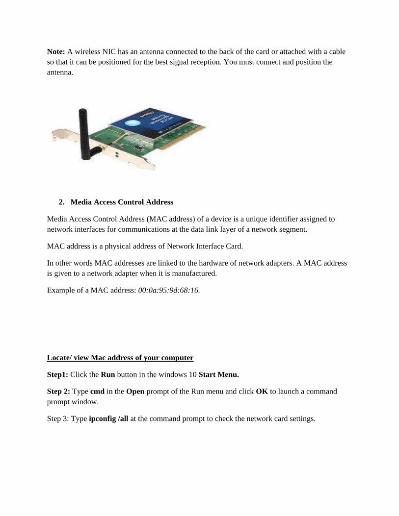
Note: A wireless NIC has an antenna connected to the back of the card or attached with a cable
so that it can be positioned for the best signal reception. You must connect and position the
antenna.
2. Media Access Control Address
Media Access Control Address (MAC address) of a device is a unique identifier assigned to
network interfaces for communications at the data link layer of a network segment.
MAC address is a physical address of Network Interface Card.
In other words MAC addresses are linked to the hardware of network adapters. A MAC address
is given to a network adapter when it is manufactured.
Example of a MAC address: 00:0a:95:9d:68:16.
Locate/ view Mac address of your computer
Step1: Click the Run button in the windows 10 Start Menu.
Step 2: Type cmd in the Open prompt of the Run menu and click OK to launch a command
prompt window.
Step 3: Type ipconfig /all at the command prompt to check the network card settings.

Step4: MAC address is listed by ipconfig under Physical Address
RJ 45 Connector and Port
A registered jack (RJ) is a standardized physical network interface for connecting
telecommunications or data equipment. The physical connectors that registered jacks use are
mainly of the modular connector and 50-pin miniature ribbon connector types.
The RJ45 port is the network port on a computer. This socket has many names. It is also known
as the Ethernet port, the network adapter, the network jack or the RJ45 jack.
3.2.NETWORK TRANSMISSION MEDIUM
3.2.1.GUIDED TRANSMISSION MEDIA
A wide variety of networking cables are Coaxial and twisted-pair cables which use electrical
signals over copper to transmit data. Fiber-optic cables use light signals to transmit data. These
cables differ in bandwidth, size, and cost.
1. Coaxial cable: is used by both cable television companies and satellite communication
systems and it carries data in the form of electrical signals.
There are several types of coaxial cable:
➢ Thicknet or 10BASE5 - Used in networks and operated at 10 Mb/s with a maximum length
of 1640.4 ft (500 m).
➢ Thinnet 10BASE2 - Used in networks and operated at 10 Mb/s with a maximum length of
607 ft (185 m).
2. Fiber optic cable: unlike TP and Coaxial cables, fiber optic cables transmit data using
pulses of light. They are constructed of either glass or plastic, neither of which conducts
electricity. They are not normally found in home or small business environments but
widely used in enterprise environments and large data centers where the interference is a
problem.
3. Twisted-pair copper cabling
Twisted-pair is a type of copper cabling used for telephone communications and most Ethernet
networks. The pair is twisted to provide protection against crosstalk, which is the noise generated
by adjacent pairs of wires in the cable.
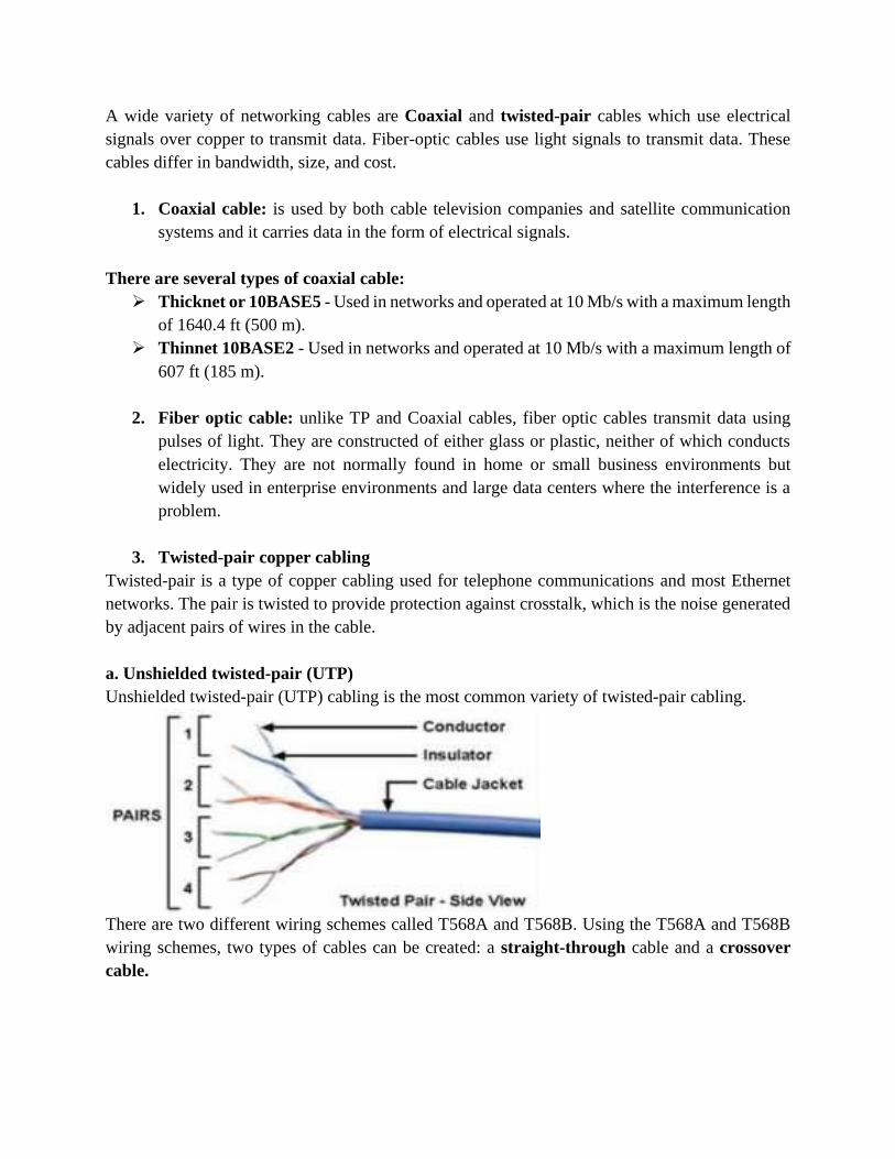
a. Unshielded twisted-pair (UTP)
Unshielded twisted-pair (UTP) cabling is the most common variety of twisted-pair cabling.
There are two different wiring schemes called T568A and T568B. Using the T568A and T568B
wiring schemes, two types of cables can be created: a straight-through cable and a crossover
cable.
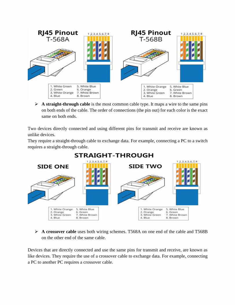
➢ A straight-through cable is the most common cable type. It maps a wire to the same pins
on both ends of the cable. The order of connections (the pin out) for each color is the exact
same on both ends.
Two devices directly connected and using different pins for transmit and receive are known as
unlike devices.
They require a straight-through cable to exchange data. For example, connecting a PC to a switch
requires a straight-through cable.
➢ A crossover cable uses both wiring schemes. T568A on one end of the cable and T568B
on the other end of the same cable.
Devices that are directly connected and use the same pins for transmit and receive, are known as
like devices. They require the use of a crossover cable to exchange data. For example, connecting
a PC to another PC requires a crossover cable.
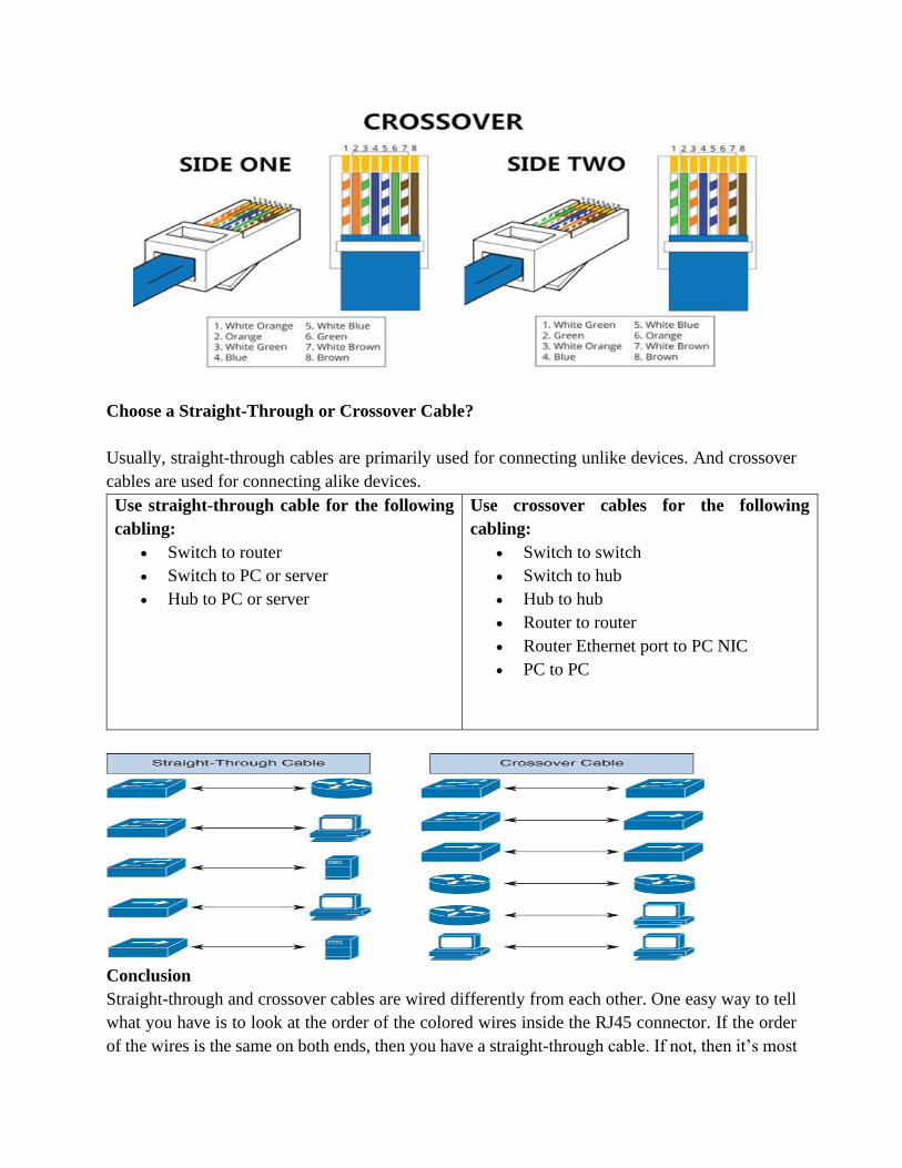
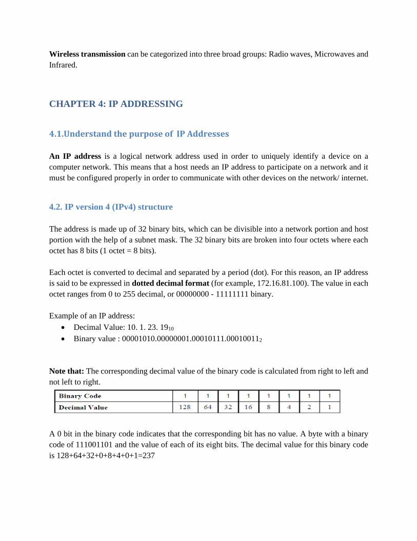
Choose a Straight-Through or Crossover Cable?
Usually, straight-through cables are primarily used for connecting unlike devices. And crossover
cables are used for connecting alike devices.
Use straight-through cable for the following
cabling:
• Switch to router
• Switch to PC or server
• Hub to PC or server
Use crossover cables for the following
cabling:
• Switch to switch
• Switch to hub
• Hub to hub
• Router to router
• Router Ethernet port to PC NIC
• PC to PC
Conclusion
Straight-through and crossover cables are wired differently from each other. One easy way to tell
what you have is to look at the order of the colored wires inside the RJ45 connector. If the order
of the wires is the same on both ends, then you have a straight-through cable. If not, then it’s most

likely a crossover cable or was wired wrong. At present, the straight-through cable is much more
popular than crossover cable and is widely used by people. FS.COM provides a full range straight-
through Cat5e, Cat6, Cat6a and Cat7 Ethernet patch cables with many lengths and colors options.
1.2.1.1 APPLICATION ACTIVITY ( Lab session)
• Task one: is to make a straight cable.
Requirement:
1. Unshielded twisted pair (UTP) patch cable.
2. Modular connector (8P8C plug or RJ45)
3. RJ 45 Crimping tool
4. Cable tester (optional, but recommended)
Step 1: Strip the cable jacket about 1.5 inch down from the end.
Step 2: Spread the four pairs of twisted wire apart.
Step 3: Untwist the wire pairs and neatly align them in the T568B orientation.
Step 4: Cut the wires as straight as possible, about 0.5 inch above the end of the jacket.

Step 5: Carefully insert the wires all the way into the modular connector, making sure that each
wire passes through the appropriate guides inside the connector.
Step 6: Push the connector inside the crimping tool and squeeze the crimper all the way down.
Step 7: Repeat steps 1-6 for the other end of the cable.
Step 8: To make sure you've successfully terminated each end of the cable, use a cable tester to
test each pin.
• Task two: use the cable made to connect two computers to see the effect.
Step 1: Fix the connectors into RJ 45 ports on both computers
Step 2: Select the Control Panel from the Start menu and choose network and internet option
Step 3: Open the Network and Sharing Center
Step 4: Try to see if the 2 computers are connected with wired network.
1.2.2 UNGUIDED TRANSMISSION MEDIA
Unguided media transport electromagnetic waves without using a physical conductor. This type
of communication is often referred to as wireless communication. The mediums used in wireless
communications are air, vacuum and even water. Air is the most commonly used medium.
Wireless transmission can be categorized into three broad groups: Radio waves, Microwaves and
Infrared.
CHAPTER 4: IP ADDRESSING
4.1.Understand the purpose of IP Addresses
An IP address is a logical network address used in order to uniquely identify a device on a
computer network. This means that a host needs an IP address to participate on a network and it
must be configured properly in order to communicate with other devices on the network/ internet.
4.2. IP version 4 (IPv4) structure
The address is made up of 32 binary bits, which can be divisible into a network portion and host
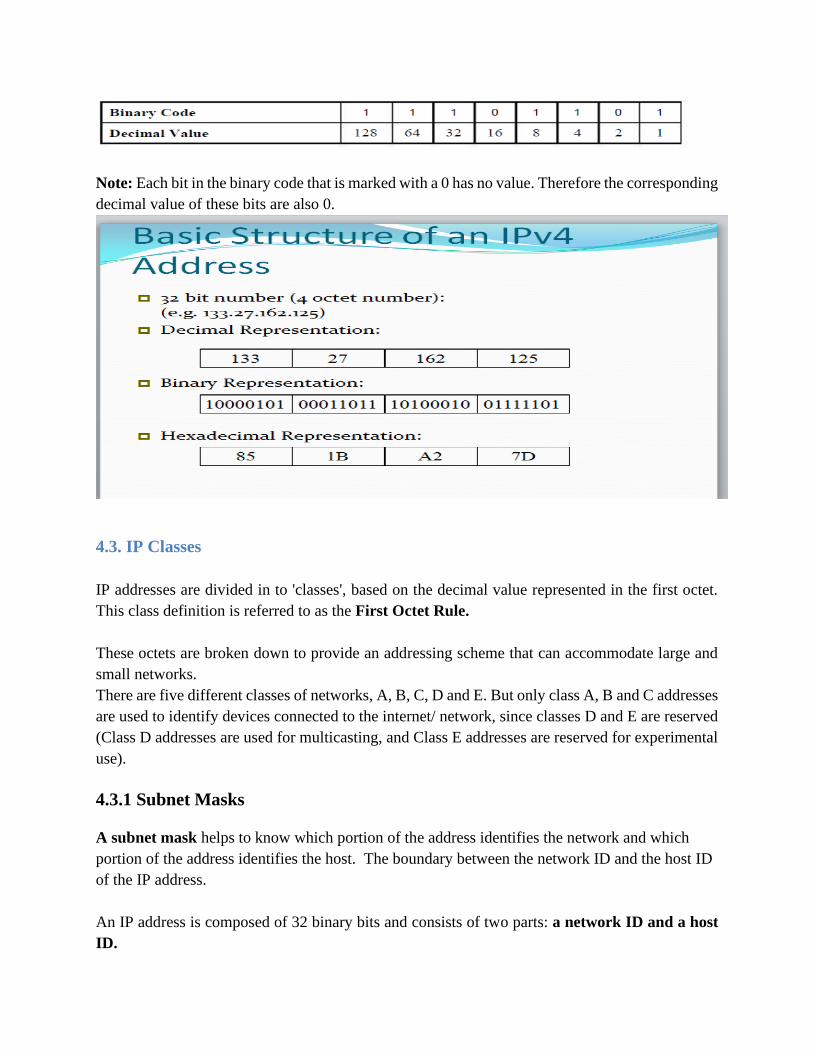
portion with the help of a subnet mask. The 32 binary bits are broken into four octets where each
octet has 8 bits (1 octet = 8 bits).
Each octet is converted to decimal and separated by a period (dot). For this reason, an IP address
is said to be expressed in dotted decimal format (for example, 172.16.81.100). The value in each
octet ranges from 0 to 255 decimal, or 00000000 - 11111111 binary.
Example of an IP address:
• Decimal Value: 10. 1. 23. 1910
• Binary value : 00001010.00000001.00010111.000100112
Note that: The corresponding decimal value of the binary code is calculated from right to left and
not left to right.
A 0 bit in the binary code indicates that the corresponding bit has no value. A byte with a binary
code of 111001101 and the value of each of its eight bits. The decimal value for this binary code
is 128+64+32+0+8+4+0+1=237
Note: Each bit in the binary code that is marked with a 0 has no value. Therefore the corresponding
decimal value of these bits are also 0.
4.3. IP Classes
IP addresses are divided in to 'classes', based on the decimal value represented in the first octet.
This class definition is referred to as the First Octet Rule.
These octets are broken down to provide an addressing scheme that can accommodate large and
small networks.
There are five different classes of networks, A, B, C, D and E. But only class A, B and C addresses
are used to identify devices connected to the internet/ network, since classes D and E are reserved
(Class D addresses are used for multicasting, and Class E addresses are reserved for experimental
use).
4.3.1 Subnet Masks
A subnet mask helps to know which portion of the address identifies the network and which
portion of the address identifies the host. The boundary between the network ID and the host ID
of the IP address.
An IP address is composed of 32 binary bits and consists of two parts: a network ID and a host
ID.
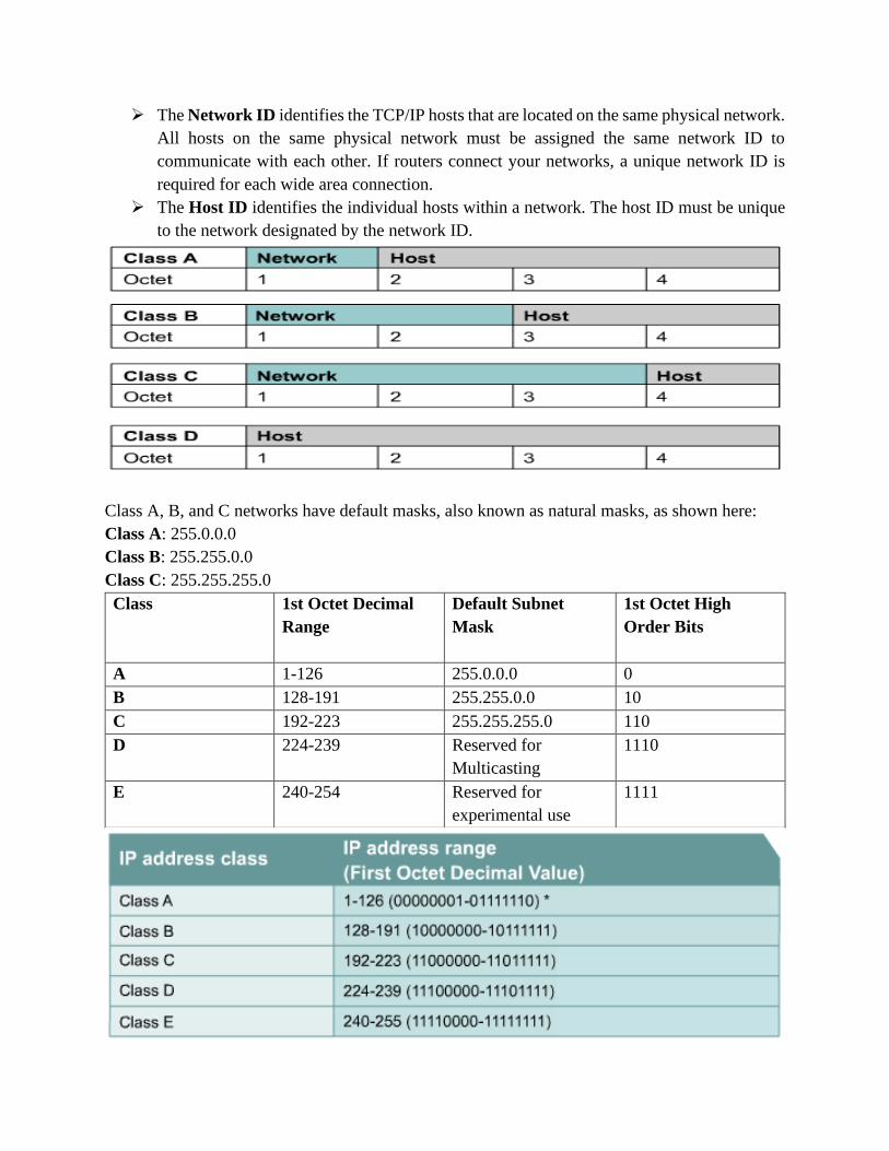
➢ The Network ID identifies the TCP/IP hosts that are located on the same physical network.
All hosts on the same physical network must be assigned the same network ID to
communicate with each other. If routers connect your networks, a unique network ID is
required for each wide area connection.
➢ The Host ID identifies the individual hosts within a network. The host ID must be unique
to the network designated by the network ID.
Class A, B, and C networks have default masks, also known as natural masks, as shown here:
Class A: 255.0.0.0
Class B: 255.255.0.0
Class C: 255.255.255.0
Class
1st Octet Decimal
Range
Default Subnet
Mask
1st Octet High
Order Bits
A 1-126 255.0.0.0 0
B 128-191 255.255.0.0 10
C 192-223 255.255.255.0 110
D 224-239 Reserved for
Multicasting
1110
E 240-254 Reserved for
experimental use
1111

Characteristics of IP classes
➢ The networks that use Class A addresses can theoretically support a maximum of 256
networks but the first and the last address cannot be used. The first address is the network
address and the last address is the broadcast address.
For example, a network with an IP address of 10.10.11.12 has a network ID of 10.0.0.0, the first
address, and a broadcast address of 10.255.255.255, the last address. Then, networks with a Class
A IP address space can support a maximum of 254 networks (28-2) and 16,777,214 hosts (224-2).
Consequently, Class A addresses are used for a few networks with a very large number of hosts
on each network.
➢ The networks that use Class B addresses can support a maximum of 65,534 networks (216-
2) and 65,534 hosts. Consequently, Class B addresses are used for a reasonable number of
medium sized networks.
Note: IP addresses with a first octet of 127, i.e. 127.0.0.0 through 127.255.255.255 do not fall in
either the Class A address range or the Class B address range. IP addresses that have a first octet
of 127 are reserved for diagnostics purposes.
➢ The networks that use Class C addresses can support a maximum of 16,777,214 networks
and 254 hosts. Consequently, Class C addresses are used for a large number of networks
with a relatively small number of hosts on each network.
➢ Class D addresses are in the range 224.0.0.0 through 239.255.255.255. These addresses
are reserved for multicast transmissions.
➢ Class E addresses are in the range 240.0.0.0 through 254.255.255.255. These addresses
are reserved for experimental use.
Note: InterNIC has reserved a number of IP address range, including 169.0.0.1 through
169.253.255.254, which has been reserved by for future use; 0.0.0.0, which was originally defined
for use as a broadcast address; and 127.0.0.0, which is used as the loopback address. 128.0.0.0,
191.255.0.0, 192.0.0.0, and 223.255.255.0 also are reserved.
4.3.2.Private IP Addressing

Most organizations have a number of computers that will never be connected to the Internet. These
computers do not need globally unique IP addresses but must be unique within the organization’s
network.
Thus, an organization could use any network number(s) it wanted, regardless of whether those
network number(s) are in use on the Internet or not. However, a set of IP addresses from Class A,
Class B and Class C has been set aside for use in private networks and has been defined in RFC
1918. This RFC defines a set of networks that not be assigned to any organization as a registered
network number to be used on the Internet. These network numbers allow organizations to use
unregistered network numbers that are not used by anyone else in the public Internet. However,
no organization is allowed to advertise these networks using a routing protocol on the Internet.
Range of IP Addresses
Class Number of Networks
10.0.0.0 to 10.255.255.255
A
1
172.16.0.0 to 172.31.255.255
B 16
192.168.0.0 to
192.168.255.255
C 256
Network Masks
The Classless Inter domain Routing (CIDR) notation, or prefix notation is in essence an
adaptation of the Dotted Decimal Format and represents the subnet mask as a number of bits used
for the network ID. This number of bits is indicated after the IP address by the number that follows
the slash (/) symbol.
For example, the CIDR notation IP address 140.12.2.128/20 indicates that the first 20 bits of the
IP address is used for the subnet mask, i.e., the first 20 bits are all 1s. Then, the subnet mask
expressed in binary format is 11111111.11111111.11110000.00000000, being represented in
dotted decimal format as 255.255.240.0. In addition, the routing protocols must send the mask
with the routing update.
“Network Masks” help define which bits describe the Network Part and which for the Host Part
Different Representations:
➢ decimal dot notation: 255.255.224.0
➢ binary: 11111111 11111111 11100000 00000000
➢ hexadecimal: 0xFFFFE000
➢ Number of network bits: /19, count the 1's in the binary representation.
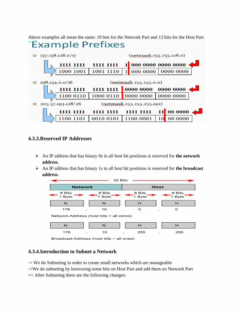
Above examples all mean the same: 19 bits for the Network Part and 13 bits for the Host Part.
4.3.3.Reserved IP Addresses
➢ An IP address that has binary 0s in all host bit positions is reserved for the network
address.
➢ An IP address that has binary 1s in all host bit positions is reserved for the broadcast
address.
4.3.4.Introduction to Subnet a Network
-> We do Subneting in order to create small networks which are manageable
->We do subneting by borrowing some bits on Host Part and add them on Network Part
=> After Subneting there are the following changes:
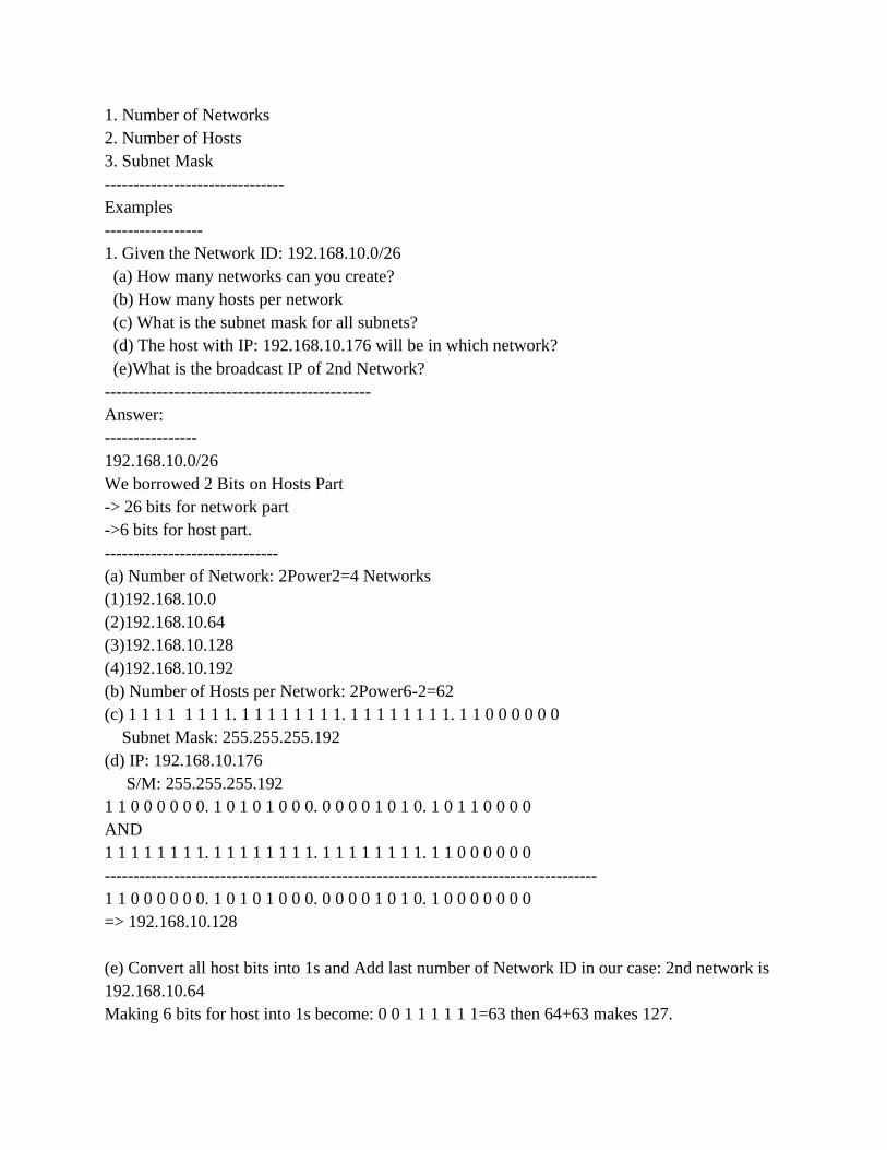
1. Number of Networks
2. Number of Hosts
3. Subnet Mask
-------------------------------
Examples
-----------------
1. Given the Network ID: 192.168.10.0/26
(a) How many networks can you create?
(b) How many hosts per network
(c) What is the subnet mask for all subnets?
(d) The host with IP: 192.168.10.176 will be in which network?
(e)What is the broadcast IP of 2nd Network?
----------------------------------------------
Answer:
----------------
192.168.10.0/26
We borrowed 2 Bits on Hosts Part
-> 26 bits for network part
->6 bits for host part.
------------------------------
(a) Number of Network: 2Power2=4 Networks
(1)192.168.10.0
(2)192.168.10.64
(3)192.168.10.128
(4)192.168.10.192
(b) Number of Hosts per Network: 2Power6-2=62
(c) 1 1 1 1 1 1 1 1. 1 1 1 1 1 1 1 1. 1 1 1 1 1 1 1 1. 1 1 0 0 0 0 0 0
Subnet Mask: 255.255.255.192
(d) IP: 192.168.10.176
S/M: 255.255.255.192
1 1 0 0 0 0 0 0. 1 0 1 0 1 0 0 0. 0 0 0 0 1 0 1 0. 1 0 1 1 0 0 0 0
AND
1 1 1 1 1 1 1 1. 1 1 1 1 1 1 1 1. 1 1 1 1 1 1 1 1. 1 1 0 0 0 0 0 0
-------------------------------------------------------------------------------------
1 1 0 0 0 0 0 0. 1 0 1 0 1 0 0 0. 0 0 0 0 1 0 1 0. 1 0 0 0 0 0 0 0
=> 192.168.10.128
(e) Convert all host bits into 1s and Add last number of Network ID in our case: 2nd network is
192.168.10.64
Making 6 bits for host into 1s become: 0 0 1 1 1 1 1 1=63 then 64+63 makes 127.
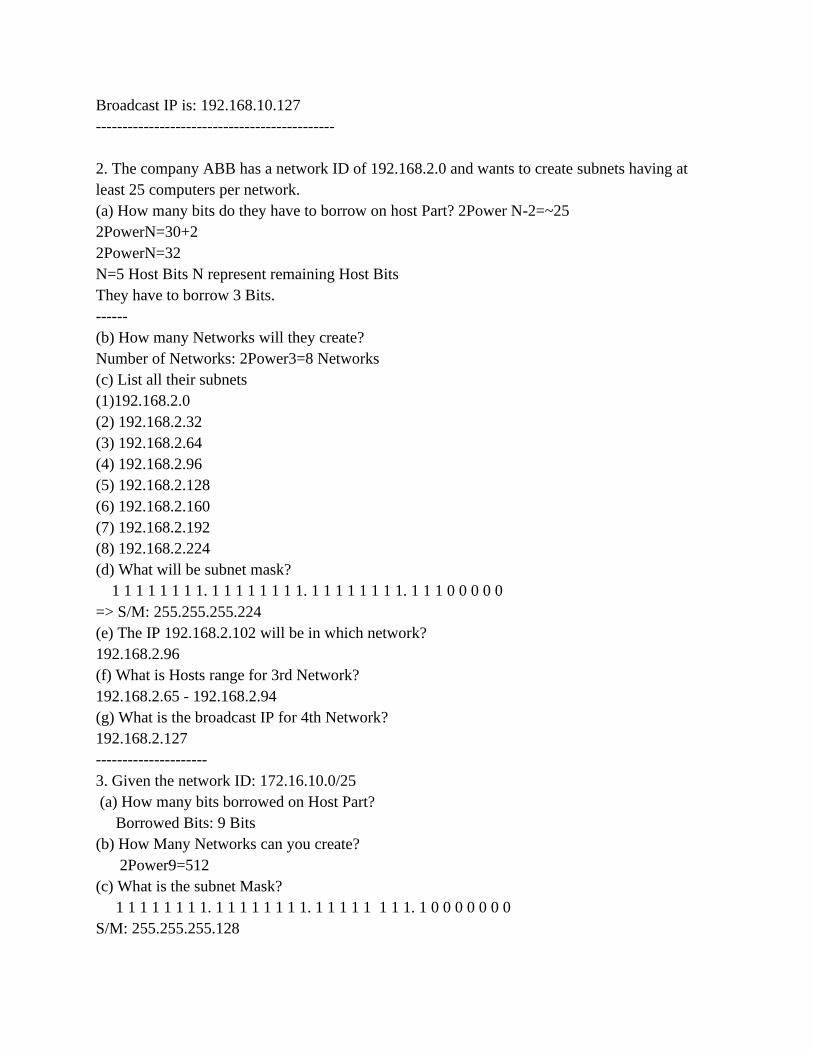
Broadcast IP is: 192.168.10.127
---------------------------------------------
2. The company ABB has a network ID of 192.168.2.0 and wants to create subnets having at
least 25 computers per network.
(a) How many bits do they have to borrow on host Part? 2Power N-2=~25
2PowerN=30+2
2PowerN=32
N=5 Host Bits N represent remaining Host Bits
They have to borrow 3 Bits.
------
(b) How many Networks will they create?
Number of Networks: 2Power3=8 Networks
(c) List all their subnets
(1)192.168.2.0
(2) 192.168.2.32
(3) 192.168.2.64
(4) 192.168.2.96
(5) 192.168.2.128
(6) 192.168.2.160
(7) 192.168.2.192
(8) 192.168.2.224
(d) What will be subnet mask?
1 1 1 1 1 1 1 1. 1 1 1 1 1 1 1 1. 1 1 1 1 1 1 1 1. 1 1 1 0 0 0 0 0
=> S/M: 255.255.255.224
(e) The IP 192.168.2.102 will be in which network?
192.168.2.96
(f) What is Hosts range for 3rd Network?
192.168.2.65 - 192.168.2.94
(g) What is the broadcast IP for 4th Network?
192.168.2.127
---------------------
3. Given the network ID: 172.16.10.0/25
(a) How many bits borrowed on Host Part?
Borrowed Bits: 9 Bits
(b) How Many Networks can you create?
2Power9=512
(c) What is the subnet Mask?
1 1 1 1 1 1 1 1. 1 1 1 1 1 1 1 1. 1 1 1 1 1 1 1 1. 1 0 0 0 0 0 0 0
S/M: 255.255.255.128

(d) The host 172.16.10.113 is in which network?
1 0 1 0 1 1 0 0. 0 0 0 1 0 0 0 0. 0 0 0 0 1 0 1 0. 0 1 1 0 1 0 1 0
AND
1 1 1 1 1 1 1 1. 1 1 1 1 1 1 1 1. 1 1 1 1 1 1 1 1. 1 0 0 0 0 0 0 0
-----------------------------------------------------------------------------------
1 0 1 0 1 1 0 0. 0 0 0 1 0 0 0 0. 0 0 0 0 1 0 1 0.0 0 0 0 0 0 0 0
=> 172. 16. 10.0
(e) What is broadcast for last network?
172.16.255.255
4.3.4.1 Determining the Network ID using the Logical AND Operation
When an IP address is assigned to an interface, it is configured with the subnet mask. Although
represented in a dotted decimal format, the router converts the IP address and the subnet mask into
binary and performs a logical AND operation to find the network portion of the address, i.e., the
network ID. To perform a logical AND, the IP address is written out in binary, with the subnet or
Internet mask written beneath it in binary.
Each binary digit of the address is then AND with the corresponding binary digit of the mask. The
AND operation has two rules: 1 AND 1 is 1; and 0 AND 1 or 0 remains 0. Essentially, the logical
AND operation removes the host ID from the IP address.
IP address:
IP subnet mask:
IP address in binary:
IP subnet mask in binary:
The result of the logical AND in binary:
The result of the logical AND in dotted
decimal format:
140.12.26.128
255.255.240.0
10001100.00001100.00011010.10000000
11111111.11111111.11110000.00000000
10001100.00001100.00000000.00000000
140.12.16.0
FIGURE shows The Logical AND Operation.
In the above example, the network to which the host 140.12.26.128 belongs has the network ID of
140.12.16.0. Once the network ID is determined, the router can perform a search on the routing
table to see whether it can route to the remote network. Therefore, the correct mask is essential to
ensure that traffic can be directed through the overall network.
4.4.Internet Protocol Version 6 (IPv6)
IPv6 addresses are 128 bits in length and written as a string of hexadecimal values. Every 4 bits is
represented by a single hexadecimal digit for a total of 32 hexadecimal values. It was intended to

replace the widely used Internet Protocol Version 4 (IPv4) that is considered the backbone of the
modern Internet. IPv6 is often referred to as the "next generation Internet" because of its expanded
capabilities and its growth through recent large scale deployments.
IP version 6 (IPv6) has been defined and developed.
IPv6 uses 128 bits rather than the 32 bits currently used in IPv4.
IPv6 uses hexadecimal numbers to represent the 128 bits.
CHAPTER 5: CONFIGURING AND TESTING NETWORKS
5.1.IP address assignment
5.1.1.Static IP assignment
You assign the following IP address configuration information to a host manually:
➢ IP address - identifies the computer on the network.
➢ Subnet mask - is used to identify the network on which the computer is connected.
➢ Default gateway - identifies the device that the computer uses to access the Internet or
another network.
➢ Optional values - such as the preferred Domain Name System (DNS) server address and
the alternate DNS server address.

Note that: host on the same network should have the Network id.
Static IP assignment
STEP 1: Right-click on the Start button, then go to Network Connections from control panel.
STEP 2: Right-click on the network connection your computer is currently using, then
Select properties.
STEP 3: Select Internet Protocol Version 4 (IPv4) from the list, then click the Properties button.

STEP 4: Select the Use the following IP address option.
NOTE: When assigning a static IP address, make sure to set a value that will not conflict with
others on your network. You may refer to your router documentation for the range of IP address
that it assigns to its devices.
STEP 5: Next to the IP address field, enter the IP address value you want to assign on the
computer.
NOTE: If the DHCP range of your router is from let’s say, 192.168.1.100-200, you can use any
range from 192.168.1.2-99 for example.
STEP 6: In the Subnet mask field, enter “255.255.255.0.”
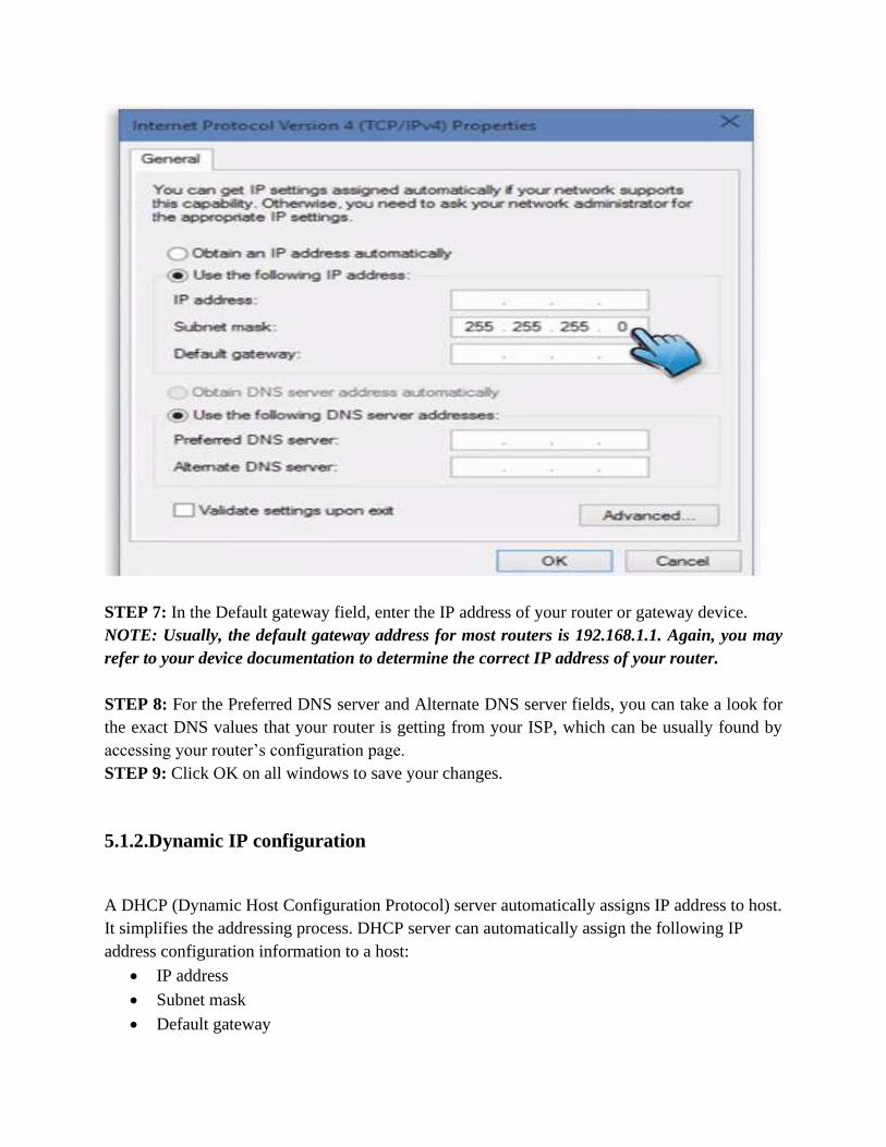
STEP 7: In the Default gateway field, enter the IP address of your router or gateway device.
NOTE: Usually, the default gateway address for most routers is 192.168.1.1. Again, you may
refer to your device documentation to determine the correct IP address of your router.
STEP 8: For the Preferred DNS server and Alternate DNS server fields, you can take a look for
the exact DNS values that your router is getting from your ISP, which can be usually found by
accessing your router’s configuration page.
STEP 9: Click OK on all windows to save your changes.
5.1.2.Dynamic IP configuration
A DHCP (Dynamic Host Configuration Protocol) server automatically assigns IP address to host.
It simplifies the addressing process. DHCP server can automatically assign the following IP
address configuration information to a host:
• IP address
• Subnet mask
• Default gateway
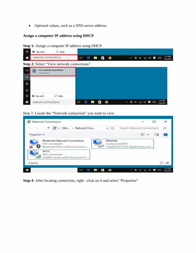
• Optional values, such as a DNS server address.
Assign a computer IP address using DHCP
Step 1: Assign a computer IP address using DHCP
Step 2: Select “View network connections”.
Step 3: Locate the “Network connection” you want to view
Step 4: After locating connection, right –click on it and select “Properties”
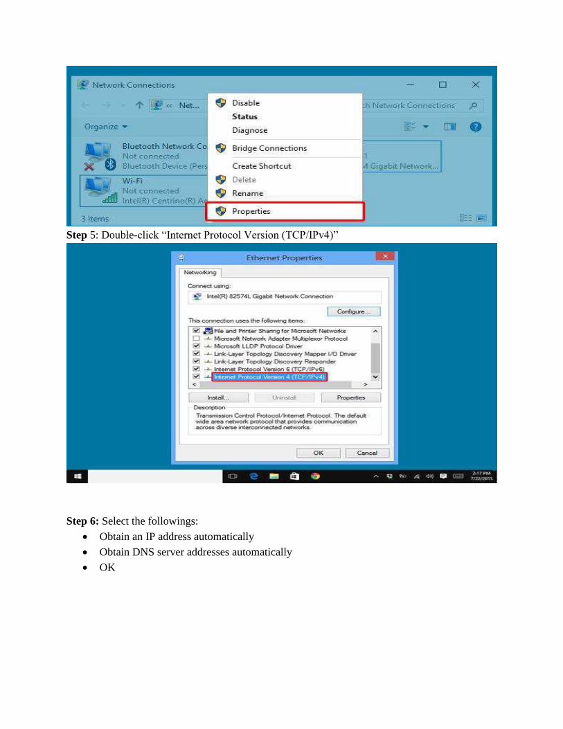
Step 5: Double-click “Internet Protocol Version (TCP/IPv4)”
Step 6: Select the followings:
• Obtain an IP address automatically
• Obtain DNS server addresses automatically
• OK
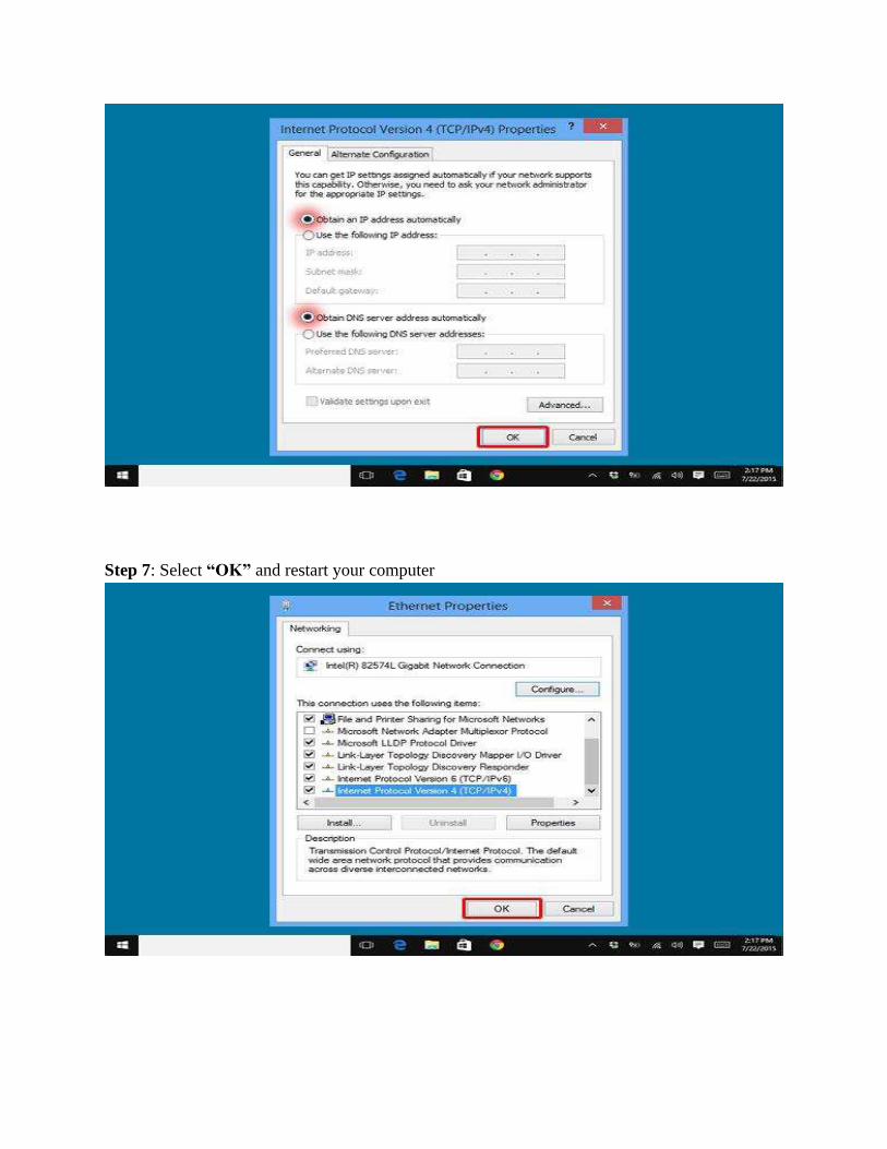
Step 7: Select “OK” and restart your computer
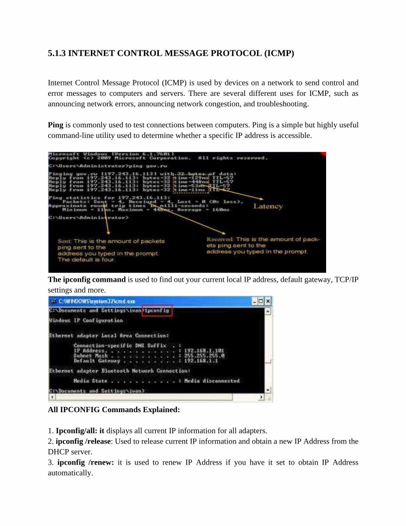
5.1.3 INTERNET CONTROL MESSAGE PROTOCOL (ICMP)
Internet Control Message Protocol (ICMP) is used by devices on a network to send control and
error messages to computers and servers. There are several different uses for ICMP, such as
announcing network errors, announcing network congestion, and troubleshooting.
Ping is commonly used to test connections between computers. Ping is a simple but highly useful
command-line utility used to determine whether a specific IP address is accessible.
The ipconfig command is used to find out your current local IP address, default gateway, TCP/IP
settings and more.
All IPCONFIG Commands Explained:
1. Ipconfig/all: it displays all current IP information for all adapters.
2. ipconfig /release: Used to release current IP information and obtain a new IP Address from the
DHCP server.
3. ipconfig /renew: it is used to renew IP Address if you have it set to obtain IP Address
automatically.

Common problems on networks:
Four common network problem categories:
1. Everything is slow/not working
2. Internet is slow, server access is normal
3. Server access is slow/not working, Internet access seems normal
4. Single computer, room of computers, area of building is slow/not working
Ping around
Get to a command prompt
Run “ipconfig”
Note your default gateway
Run “Ping <default gateway>”
No response, your router may not be working
Run “Ping <known >
No response, your connection to the outside world (Geomax/T1 etc)
is down
TRACERT
The TRACERT or TRACEROUTE utility can be used to check connectivity over longer
distances. If you can access some locations on the network, but not others, you can use
TRACEROUTE to determine which link in the chain is broken.
5.1.4.Configuration of routers and access points
A wireless router is a device that performs the functions of a router and also includes the functions
of a wireless access point. It is used to provide access to the Internet or a private computer network.
Routers operate at the Network layer (Layer 3) of the OSI Model.
The Wireless access points (APs or WAPs) are networking devices that allow wireless Wi-Fi
devices to connect to a wired network.
The placement of routers in a network:
Configuring a wireless router
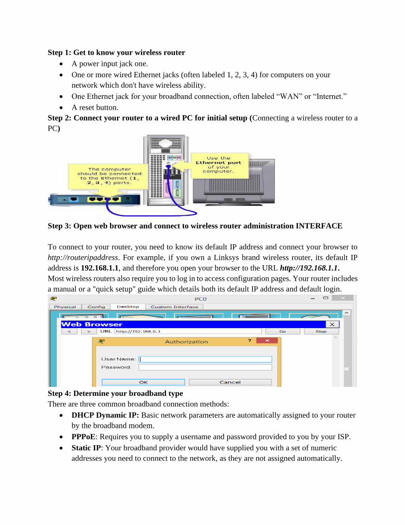
Step 1: Get to know your wireless router
• A power input jack one.
• One or more wired Ethernet jacks (often labeled 1, 2, 3, 4) for computers on your
network which don't have wireless ability.
• One Ethernet jack for your broadband connection, often labeled “WAN” or “Internet.”
• A reset button.
Step 2: Connect your router to a wired PC for initial setup (Connecting a wireless router to a
PC)
Step 3: Open web browser and connect to wireless router administration INTERFACE
To connect to your router, you need to know its default IP address and connect your browser to
http://routeripaddress. For example, if you own a Linksys brand wireless router, its default IP
address is 192.168.1.1, and therefore you open your browser to the URL http://192.168.1.1.
Most wireless routers also require you to log in to access configuration pages. Your router includes
a manual or a "quick setup" guide which details both its default IP address and default login.
Step 4: Determine your broadband type
There are three common broadband connection methods:
• DHCP Dynamic IP: Basic network parameters are automatically assigned to your router
by the broadband modem.
• PPPoE: Requires you to supply a username and password provided to you by your ISP.
• Static IP: Your broadband provider would have supplied you with a set of numeric
addresses you need to connect to the network, as they are not assigned automatically.
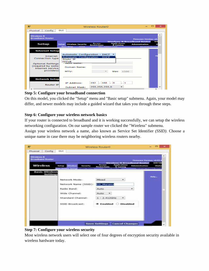
Step 5: Configure your broadband connection
On this model, you clicked the "Setup" menu and "Basic setup" submenu. Again, your model may
differ, and newer models may include a guided wizard that takes you through these steps.
Step 6: Configure your wireless network basics
If your router is connected to broadband and it is working successfully, we can setup the wireless
networking configuration. On our sample router we clicked the "Wireless" submenu.
Assign your wireless network a name, also known as Service Set Identifier (SSID). Choose a
unique name in case there may be neighboring wireless routers nearby.
Step 7: Configure your wireless security
Most wireless network users will select one of four degrees of encryption security available in
wireless hardware today.
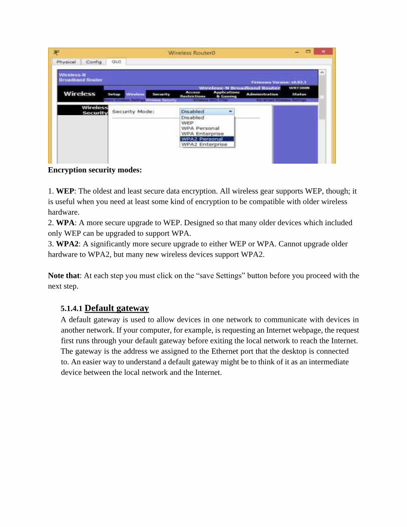
Encryption security modes:
1. WEP: The oldest and least secure data encryption. All wireless gear supports WEP, though; it
is useful when you need at least some kind of encryption to be compatible with older wireless
hardware.
2. WPA: A more secure upgrade to WEP. Designed so that many older devices which included
only WEP can be upgraded to support WPA.
3. WPA2: A significantly more secure upgrade to either WEP or WPA. Cannot upgrade older
hardware to WPA2, but many new wireless devices support WPA2.
Note that: At each step you must click on the “save Settings” button before you proceed with the
next step.
5.1.4.1 Default gateway
A default gateway is used to allow devices in one network to communicate with devices in
another network. If your computer, for example, is requesting an Internet webpage, the request
first runs through your default gateway before exiting the local network to reach the Internet.
The gateway is the address we assigned to the Ethernet port that the desktop is connected
to. An easier way to understand a default gateway might be to think of it as an intermediate
device between the local network and the Internet.
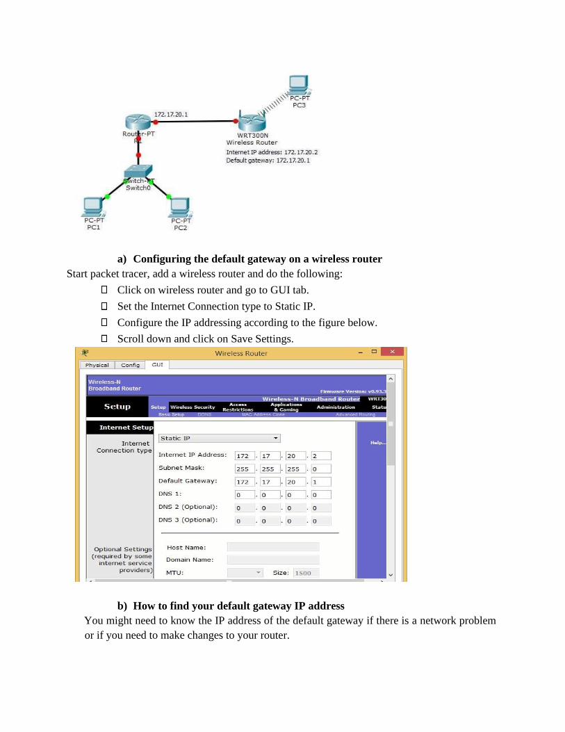
a) Configuring the default gateway on a wireless router
Start packet tracer, add a wireless router and do the following:
Click on wireless router and go to GUI tab.
Set the Internet Connection type to Static IP.
Configure the IP addressing according to the figure below.
Scroll down and click on Save Settings.
b) How to find your default gateway IP address
You might need to know the IP address of the default gateway if there is a network problem
or if you need to make changes to your router.

In Microsoft Windows, the IP address of a computer's default gateway can be
accessed through Command Prompt with the ipconfig command, as well as through
the Control Panel.
The netstat and ip route commands are used on macOS and Linux for finding the
default gateway address.
c) Configuring a default gateway on a desktop
Open the control panel
Click on Network and Internet
Click on Network and sharing center
Right click on wi-fi and choose properties
Click on adapter settings
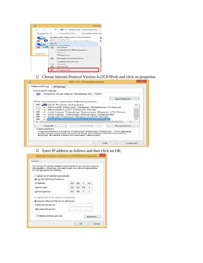
Choose Internet Protocol Version 4 (TCP/IPv4) and click on properties
Enter IP address as follows and then click on OK:
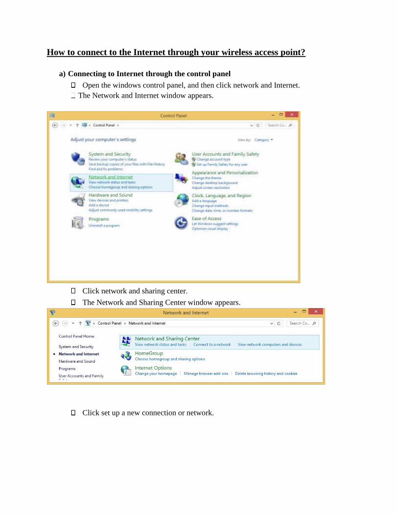
How to connect to the Internet through your wireless access point?
a) Connecting to Internet through the control panel
Open the windows control panel, and then click network and Internet.
The Network and Internet window appears.
Click network and sharing center.
The Network and Sharing Center window appears.
Click set up a new connection or network.

Set up a Connection or Network window appears.
Click Manually connect to a wireless network
Click Manually connect to a wireless network
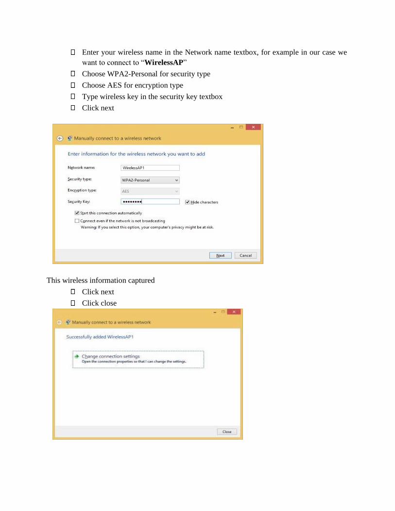
Enter your wireless name in the Network name textbox, for example in our case we
want to connect to “WirelessAP”
Choose WPA2-Personal for security type
Choose AES for encryption type
Type wireless key in the security key textbox
Click next
This wireless information captured
Click next
Click close
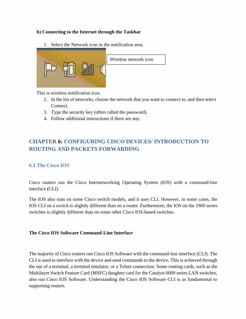
b) Connecting to the Internet through the Taskbar
1. Select the Network icon in the notification area.
Wireless network icon
This is wireless notification icon.
2. In the list of networks, choose the network that you want to connect to, and then select
Connect.
3. Type the security key (often called the password).
4. Follow additional instructions if there are any.
CHAPTER 6: CONFIGURING CISCO DEVICES/ INTRODUCTION TO
ROUTING AND PACKETS FORWARDING
6.1 The Cisco IOS
Cisco routers run the Cisco Internetworking Operating System (IOS) with a command-line
interface (CLI).
The IOS also runs on some Cisco switch models, and it uses CLI. However, in some cases, the
IOS CLI on a switch is slightly different than on a router. Furthermore, the IOS on the 1900 series
switches is slightly different than on some other Cisco IOS-based switches.
The Cisco IOS Software Command-Line Interface
The majority of Cisco routers run Cisco IOS Software with the command-line interface (CLI). The
CLI is used to interface with the device and send commands to the device. This is achieved through
the use of a terminal, a terminal emulator, or a Telnet connection. Some routing cards, such as the
Multilayer Switch Feature Card (MSFC) daughter card for the Catalyst 6000 series LAN switches,
also run Cisco IOS Software. Understanding the Cisco IOS Software CLI is as fundamental to
supporting routers.
There are three ways in which you can access the CLI: you access the router through the console;
through a dialup device through a modem attached to the auxiliary port; or by using a Telnet
connection. Which ever method you use, you enter user exec mode first. User exec mode is one of
three command exec modes in the IOS user interface. Enable mode, also known as privileged mode
or Privileged exec mode, and command mode are the others. Enable mode is so named because
the enable command is used to reach this mode. User mode allows commands that are not
disruptive to be issued, with some information being displayed to the user. Privileged mode
supports a superset of commands compared to user mode. However, none of the commands in user
mode or privileged mode changes the configuration of the router.
Passwords are required for Telnet and auxiliary access as of Cisco IOS Release 12.x and later.
However, there are no preconfigured passwords; therefore, you must configure passwords for
Telnet and auxiliary access from the console first.
All Cisco routers have a console port, and most have an auxiliary port. The console port is intended
for local administrative access from an ASCII terminal or a computer using a terminal emulator.
The auxiliary port is intended for asynchronous dial access from an ASCII terminal or terminal
emulator; the auxiliary port is often used for dial backup.
The CLI Help Features
Typing? In the console displays help for all commands supported by the CLI mode. In other words,
the information supplied by using help depends on the CLI mode. If? Is typed in user mode, the
commands allowed only in privileged exec mode are not displayed. Also, help is available in
configuration mode; only configuration commands are displayed in that mode of operation. IOS
stores the commands that you type in a history buffer. The last ten commands are stored by default.
You can change the history size with the terminal history size command, where size is the number
of IOS commands for the CLI to store; this can be set to a value between 0 and 256. You can then
retrieve commands so that you do not have to retype the commands.
6.2 Introduction to routing and packet forwarding
Router: is a network device which controls or manages and secures a network and it can connect
two or more networks.
Network Device: is the device that is dedicated to supply network to the end device. Example:
router, switch, hub, bridge, repeater
End device: printer, computer, telephone, tablet etc.,
MAC address: is the physical address of an end device or node.
IP address: is the logical address given to a node on the network.
Telnet: to call the device
Ping: to request or to ask the connectivity between the devices on the network.
In router we have three user’s modes:
>: user execution mode
Router #: user privilege mode /here you can ping
Router (config)#: configuration mode /is where you configure all protocols on router.
*To access a router you will need a power cable and console cable and a computer you will install
Putty or Tera term software.
An Interface: is a logical port but a Port: is a physical connection.
Networks allow people to communicate, collaborate, and interact in many ways. Networks are
used to access web pages, talk using IP telephones, participate in video conferences, compete in
interactive gaming, shop using the Internet, complete online coursework, and more.
Ethernet switches function at the data link layer, Layer 2, and are used to forward Ethernet frames
between devices within the same network.
However, when the source IP and destination IP addresses are on different networks, the Ethernet
frame must be sent to a router.
A router connects one network to another network. The router is responsible for the delivery of
packets across different networks. The destination of the IP packet might be a web server in another
country or an email server on the local area network.

The router uses its routing table to determine the best path to use to forward a packet. It is the
responsibility of the routers to deliver those packets in a timely manner. The effectiveness of
internetwork communications depends, to a large degree, on the ability of routers to forward
packets in the most efficient way possible.
When a host sends a packet to a device on a different IP network, the packet is forwarded to the
default gateway because a host device cannot communicate directly with devices outside of the
local network. The default gateway is the destination that routes traffic from the local network to
devices on remote networks. It is often used to connect a local network to the Internet.
Because the router can route packets between networks, devices on different networks can
communicate. This chapter will introduce the router, its role in the networks, its main hardware
and software components, and the routing process. Exercises which demonstrate how to access the
router, configure basic router settings, and verify settings will be provided.
Routing helps to create routing tables which supply a wealth of information about paths to others
network.
Initial Configuration of a Router
Functions of a Router:
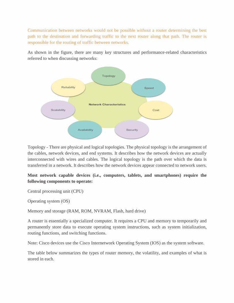
Communication between networks would not be possible without a router determining the best
path to the destination and forwarding traffic to the next router along that path. The router is
responsible for the routing of traffic between networks.
As shown in the figure, there are many key structures and performance-related characteristics
referred to when discussing networks:
Topology - There are physical and logical topologies. The physical topology is the arrangement of
the cables, network devices, and end systems. It describes how the network devices are actually
interconnected with wires and cables. The logical topology is the path over which the data is
transferred in a network. It describes how the network devices appear connected to network users.
Most network capable devices (i.e., computers, tablets, and smartphones) require the
following components to operate:
Central processing unit (CPU)
Operating system (OS)
Memory and storage (RAM, ROM, NVRAM, Flash, hard drive)
A router is essentially a specialized computer. It requires a CPU and memory to temporarily and
permanently store data to execute operating system instructions, such as system initialization,
routing functions, and switching functions.
Note: Cisco devices use the Cisco Internetwork Operating System (IOS) as the system software.
The table below summarizes the types of router memory, the volatility, and examples of what is
stored in each.

Routers store data using:
Random Access Memory (RAM) - Provides temporary storage for various applications and
processes including the running IOS, the running configuration file, various tables (i.e., IP routing
table, Ethernet ARP table) and buffers for packet processing. RAM is referred to as volatile
because it loses its contents when power is turned off.
Read-Only Memory (ROM) - Provides permanent storage for boot up instructions, basic diagnostic
software and a limited IOS in case the router cannot load the full featured IOS. ROM is firmware
and referred to as non-volatile because it does not lose its contents when power is turned off.
Non-Volatile Random Access Memory (NVRAM) - Provides permanent storage for the startup
configuration file (startup-config). NVRAM is non-volatile and does not lose its contents when
power is turned off.
Flash - Provides permanent storage for the IOS and other system-related files. The IOS is copied
from flash into RAM during the boot up process. Flash is non-volatile and does not lose its contents
when power is turned off.
Unlike a computer, a router does not have video adapters or sound card adapters. Instead, routers
have specialized ports and network interface cards to interconnect devices to other networks.
The primary functions of a router are to:
Determine the best path to send packets
Forward packets toward their destination
The router uses its routing table to determine the best path to use to forward a packet. When the
router receives a packet, it examines the destination address of the packet and uses the routing
table to search for the best path to that network. The routing table also includes the interface to be
used to forward packets for each known network. When a match is found, the router encapsulates
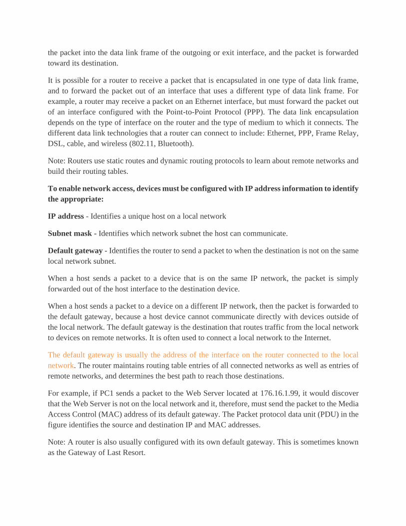
the packet into the data link frame of the outgoing or exit interface, and the packet is forwarded
toward its destination.
It is possible for a router to receive a packet that is encapsulated in one type of data link frame,
and to forward the packet out of an interface that uses a different type of data link frame. For
example, a router may receive a packet on an Ethernet interface, but must forward the packet out
of an interface configured with the Point-to-Point Protocol (PPP). The data link encapsulation
depends on the type of interface on the router and the type of medium to which it connects. The
different data link technologies that a router can connect to include: Ethernet, PPP, Frame Relay,
DSL, cable, and wireless (802.11, Bluetooth).
Note: Routers use static routes and dynamic routing protocols to learn about remote networks and
build their routing tables.
To enable network access, devices must be configured with IP address information to identify
the appropriate:
IP address - Identifies a unique host on a local network
Subnet mask - Identifies which network subnet the host can communicate.
Default gateway - Identifies the router to send a packet to when the destination is not on the same
local network subnet.
When a host sends a packet to a device that is on the same IP network, the packet is simply
forwarded out of the host interface to the destination device.
When a host sends a packet to a device on a different IP network, then the packet is forwarded to
the default gateway, because a host device cannot communicate directly with devices outside of
the local network. The default gateway is the destination that routes traffic from the local network
to devices on remote networks. It is often used to connect a local network to the Internet.
The default gateway is usually the address of the interface on the router connected to the local
network. The router maintains routing table entries of all connected networks as well as entries of
remote networks, and determines the best path to reach those destinations.
For example, if PC1 sends a packet to the Web Server located at 176.16.1.99, it would discover
that the Web Server is not on the local network and it, therefore, must send the packet to the Media
Access Control (MAC) address of its default gateway. The Packet protocol data unit (PDU) in the
figure identifies the source and destination IP and MAC addresses.
Note: A router is also usually configured with its own default gateway. This is sometimes known
as the Gateway of Last Resort.
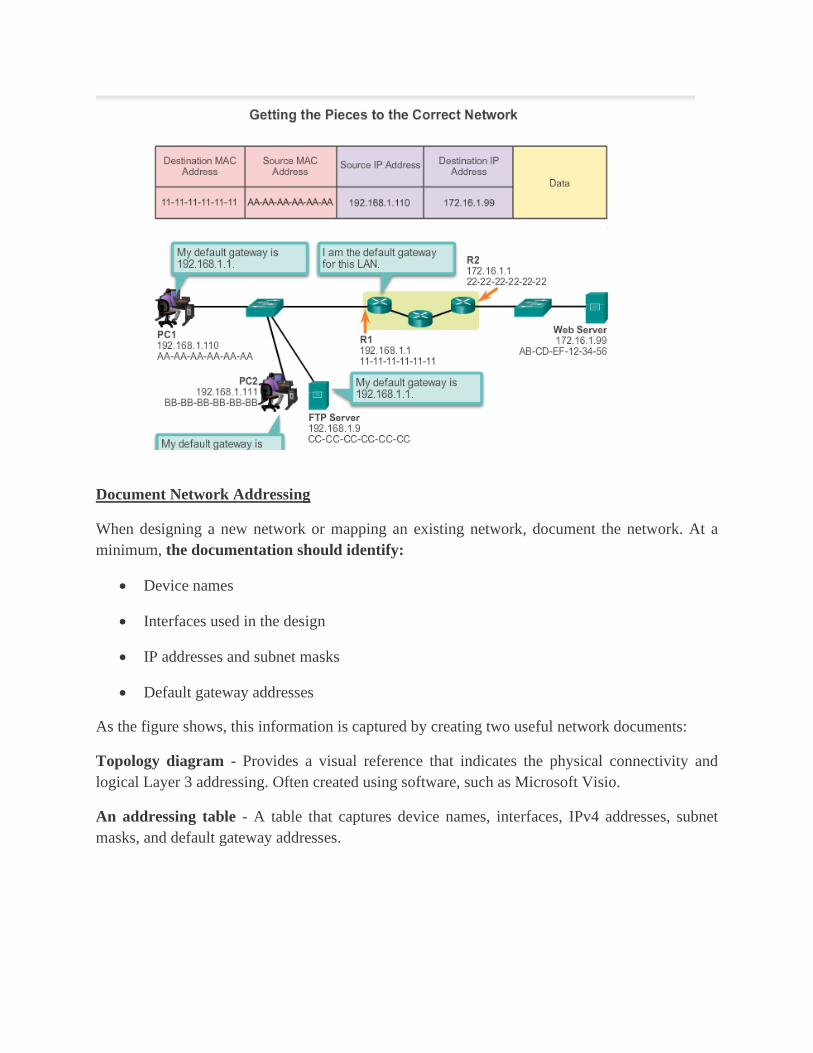
Document Network Addressing
When designing a new network or mapping an existing network, document the network. At a
minimum, the documentation should identify:
• Device names
• Interfaces used in the design
• IP addresses and subnet masks
• Default gateway addresses
As the figure shows, this information is captured by creating two useful network documents:
Topology diagram - Provides a visual reference that indicates the physical connectivity and
logical Layer 3 addressing. Often created using software, such as Microsoft Visio.
An addressing table - A table that captures device names, interfaces, IPv4 addresses, subnet
masks, and default gateway addresses.

A host can be assigned IP address information either:
Statically - The host is manually assigned the correct IP address, subnet mask, and default
gateway. The DNS server IP address can also be configured.
Dynamically - IP address information is provided by a server using the Dynamic Host
Configuration Protocol (DHCP). The DHCP server provides a valid IP address, subnet mask, and
default gateway for end devices. Other information may be provided by the server.
Statically assigned addresses are commonly used to identify specific network resources, such as
network servers and printers. They can also be used in smaller networks with few hosts. However,
most host devices acquire their IPv4 address information by accessing a DHCP server. In large
enterprises, dedicated DHCP servers providing services to many LANs are implemented. In a
smaller branch or small office setting, DHCP services can be provided by a Cisco Catalyst switch
or a Cisco ISR.
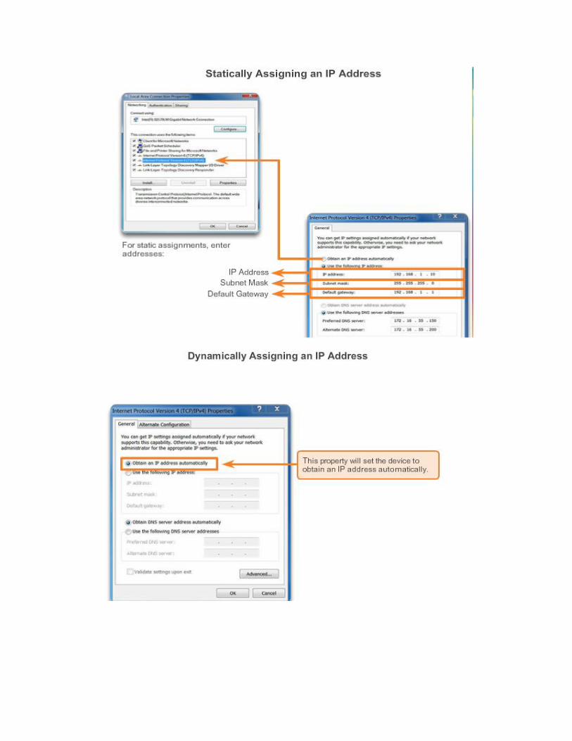

Basic Settings on a Router
Cisco routers and Cisco switches have many similarities. They support a similar modal operating
system, similar command structures, and many of the same commands. In addition, both devices
have similar initial configuration steps.
When configuring a Cisco switch or router, the following basic tasks should be performed first:
Name the device - Distinguishes it from other routers.
Secure management access - Secures privileged EXEC, user EXEC, and Telnet access, and
encrypts passwords to their highest level.
Configure a banner - Provides legal notification of unauthorized access.
Note: Always save the changes on a router and verify the basic configuration and router operations.
Figures 1 through 4 provide examples of configuring basic settings on router R1:
In Figure 1, the device is named, In Figure 2, management access is secured, In Figure 3, a banner
is configured, In Figure 4, the configuration is saved.
Use the Syntax Checker in Figure 5 to configure router R2.
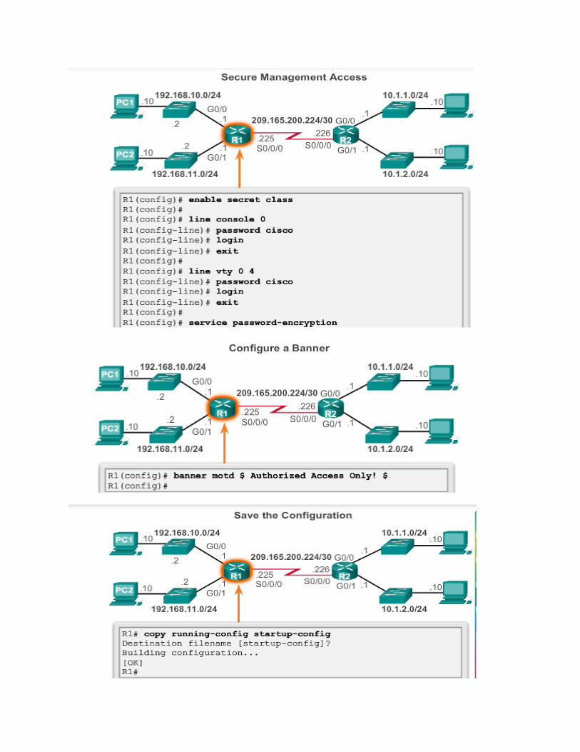

Routing is at the core of every data network, moving information across an internetwork from
source to destination. Routers are the devices responsible for the transfer of packets from one
network to the next.
Routers learn about remote networks either dynamically, using routing protocols, or manually, or
using static routes. In many cases, routers use a combination of both dynamic routing protocols
and static routes. This chapter focuses on static routing.
Static routes are very common and do not require the same amount of processing and overhead as
dynamic routing protocols.
In this chapter, sample topologies will be used to configure IPv4 and IPv6 static routes and to
present troubleshooting techniques. In the process, several important IOS commands and the
resulting output will be examined. An introduction to the routing table using both directly
connected networks and static routes will be included.
A router can learn about remote networks in one of two ways:
Manually - Remote networks are manually entered into the route table using static routes.
Dynamically - Remote routes are automatically learned using a dynamic routing protocol.
A network administrator can manually configure a static route to reach a specific network. Unlike
a dynamic routing protocol, static routes are not automatically updated and must be manually
reconfigured any time the network topology changes. A static route does not change until the
administrator manually reconfigures it.
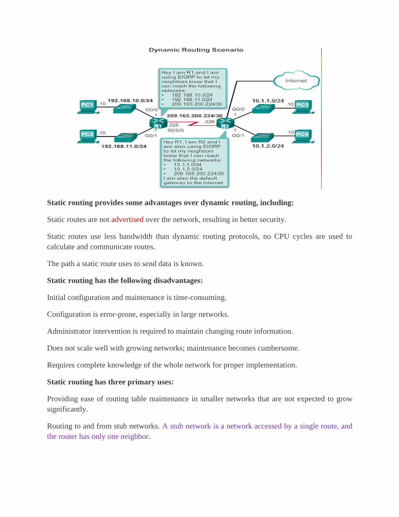
Static routing provides some advantages over dynamic routing, including:
Static routes are not advertised over the network, resulting in better security.
Static routes use less bandwidth than dynamic routing protocols, no CPU cycles are used to
calculate and communicate routes.
The path a static route uses to send data is known.
Static routing has the following disadvantages:
Initial configuration and maintenance is time-consuming.
Configuration is error-prone, especially in large networks.
Administrator intervention is required to maintain changing route information.
Does not scale well with growing networks; maintenance becomes cumbersome.
Requires complete knowledge of the whole network for proper implementation.
Static routing has three primary uses:
Providing ease of routing table maintenance in smaller networks that are not expected to grow
significantly.
Routing to and from stub networks. A stub network is a network accessed by a single route, and
the router has only one neighbor.
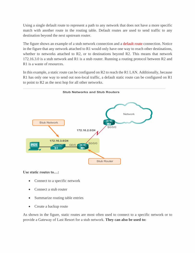
Using a single default route to represent a path to any network that does not have a more specific
match with another route in the routing table. Default routes are used to send traffic to any
destination beyond the next upstream router.
The figure shows an example of a stub network connection and a default route connection. Notice
in the figure that any network attached to R1 would only have one way to reach other destinations,
whether to networks attached to R2, or to destinations beyond R2. This means that network
172.16.3.0 is a stub network and R1 is a stub router. Running a routing protocol between R2 and
R1 is a waste of resources.
In this example, a static route can be configured on R2 to reach the R1 LAN. Additionally, because
R1 has only one way to send out non-local traffic, a default static route can be configured on R1
to point to R2 as the next hop for all other networks.
Use static routes to…:
• Connect to a specific network
• Connect a stub router
• Summarize routing table entries
• Create a backup route
As shown in the figure, static routes are most often used to connect to a specific network or to
provide a Gateway of Last Resort for a stub network. They can also be used to:

• Reduce the number of routes advertised by summarizing several contiguous networks as
one static route.
• Create a backup route in case a primary route link fails.
The following types of IPv4 and IPv6 static routes will be discussed:
• Standard static route
• Default static route
• Summary static route
• Floating static route
Both IPv4 and IPv6 support the configuration of static routes. Static routes are useful when
connecting to a specific remote network.
The figure shows that R2 can be configured with a static route to reach the stub network
172.16.3.0/24.
Note: The example is highlighting a stub network, but in fact, a static route can be used to connect
to any network.
A default static route is a route that matches all packets. A default route identifies the gateway IP
address to which the router sends all IP packets that it does not have a learned or static route. A
default static route is simply a static route with 0.0.0.0/0 as the destination IPv4 address.
Configuring a default static route creates a Gateway of Last Resort.
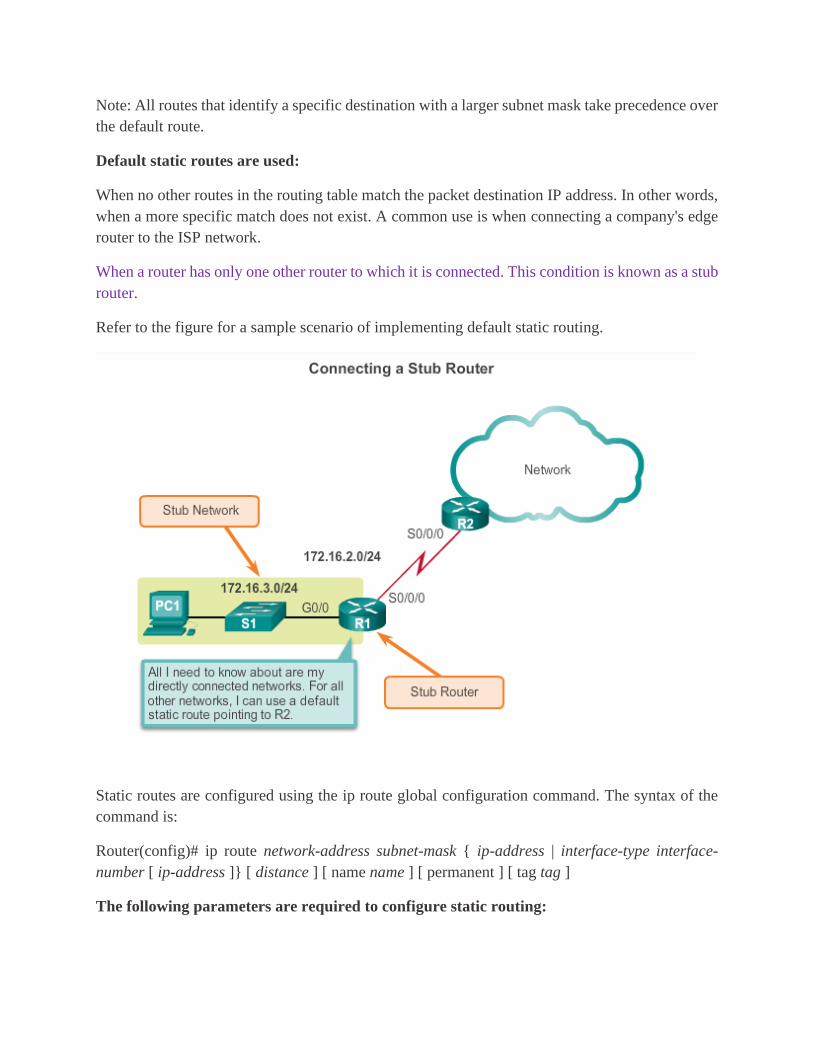
Note: All routes that identify a specific destination with a larger subnet mask take precedence over
the default route.
Default static routes are used:
When no other routes in the routing table match the packet destination IP address. In other words,
when a more specific match does not exist. A common use is when connecting a company's edge
router to the ISP network.
When a router has only one other router to which it is connected. This condition is known as a stub
router.
Refer to the figure for a sample scenario of implementing default static routing.
Static routes are configured using the ip route global configuration command. The syntax of the
command is:
Router(config)# ip route network-address subnet-mask { ip-address | interface-type interface-
number [ ip-address ]} [ distance ] [ name name ] [ permanent ] [ tag tag ]
The following parameters are required to configure static routing:
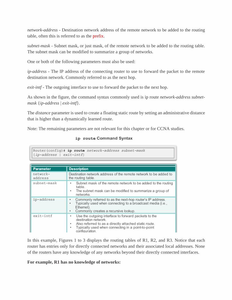
network-address - Destination network address of the remote network to be added to the routing
table, often this is referred to as the prefix.
subnet-mask - Subnet mask, or just mask, of the remote network to be added to the routing table.
The subnet mask can be modified to summarize a group of networks.
One or both of the following parameters must also be used:
ip-address - The IP address of the connecting router to use to forward the packet to the remote
destination network. Commonly referred to as the next hop.
exit-intf - The outgoing interface to use to forward the packet to the next hop.
As shown in the figure, the command syntax commonly used is ip route network-address subnet-
mask {ip-address | exit-intf}.
The distance parameter is used to create a floating static route by setting an administrative distance
that is higher than a dynamically learned route.
Note: The remaining parameters are not relevant for this chapter or for CCNA studies.
In this example, Figures 1 to 3 displays the routing tables of R1, R2, and R3. Notice that each
router has entries only for directly connected networks and their associated local addresses. None
of the routers have any knowledge of any networks beyond their directly connected interfaces.
For example, R1 has no knowledge of networks:
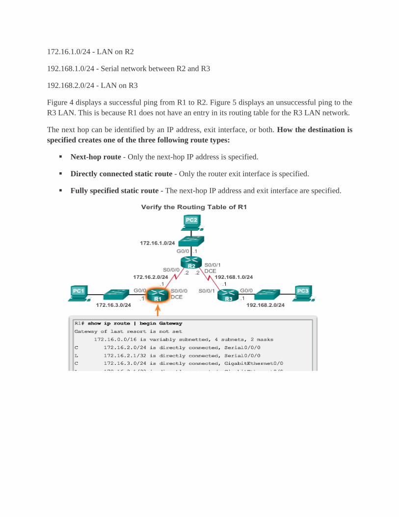
172.16.1.0/24 - LAN on R2
192.168.1.0/24 - Serial network between R2 and R3
192.168.2.0/24 - LAN on R3
Figure 4 displays a successful ping from R1 to R2. Figure 5 displays an unsuccessful ping to the
R3 LAN. This is because R1 does not have an entry in its routing table for the R3 LAN network.
The next hop can be identified by an IP address, exit interface, or both. How the destination is
specified creates one of the three following route types:
▪ Next-hop route - Only the next-hop IP address is specified.
▪ Directly connected static route - Only the router exit interface is specified.
▪ Fully specified static route - The next-hop IP address and exit interface are specified.


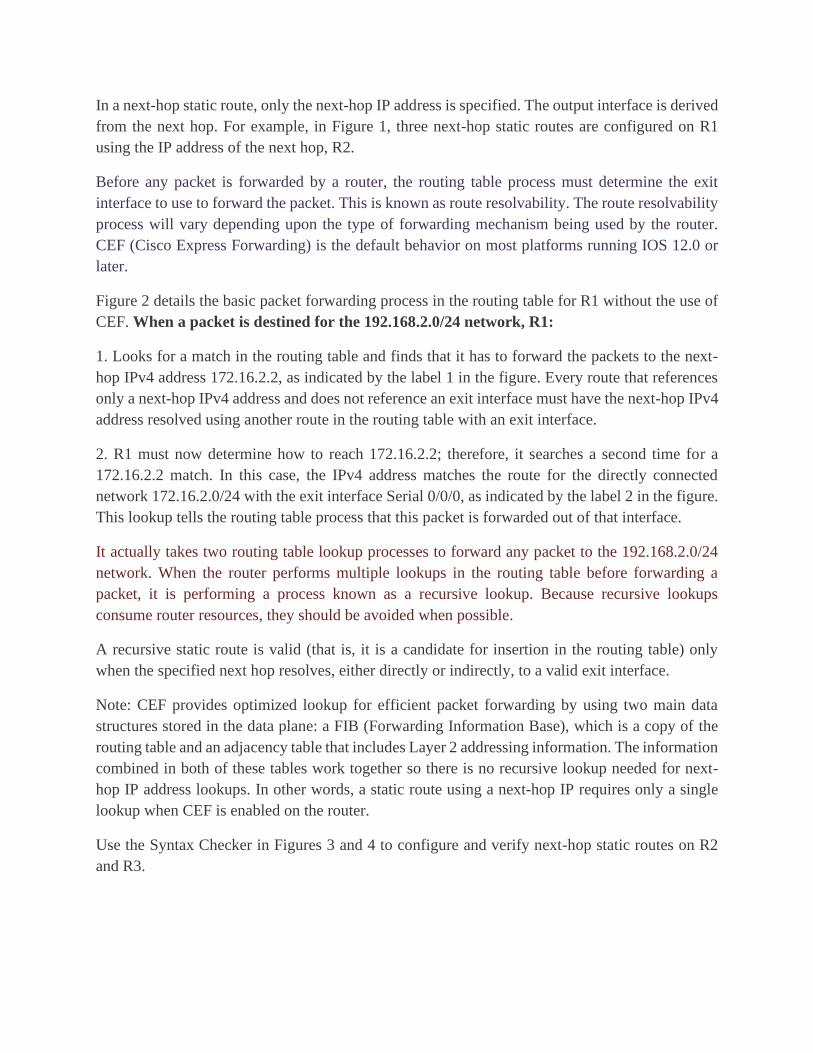
In a next-hop static route, only the next-hop IP address is specified. The output interface is derived
from the next hop. For example, in Figure 1, three next-hop static routes are configured on R1
using the IP address of the next hop, R2.
Before any packet is forwarded by a router, the routing table process must determine the exit
interface to use to forward the packet. This is known as route resolvability. The route resolvability
process will vary depending upon the type of forwarding mechanism being used by the router.
CEF (Cisco Express Forwarding) is the default behavior on most platforms running IOS 12.0 or
later.
Figure 2 details the basic packet forwarding process in the routing table for R1 without the use of
CEF. When a packet is destined for the 192.168.2.0/24 network, R1:
1. Looks for a match in the routing table and finds that it has to forward the packets to the next-
hop IPv4 address 172.16.2.2, as indicated by the label 1 in the figure. Every route that references
only a next-hop IPv4 address and does not reference an exit interface must have the next-hop IPv4
address resolved using another route in the routing table with an exit interface.
2. R1 must now determine how to reach 172.16.2.2; therefore, it searches a second time for a
172.16.2.2 match. In this case, the IPv4 address matches the route for the directly connected
network 172.16.2.0/24 with the exit interface Serial 0/0/0, as indicated by the label 2 in the figure.
This lookup tells the routing table process that this packet is forwarded out of that interface.
It actually takes two routing table lookup processes to forward any packet to the 192.168.2.0/24
network. When the router performs multiple lookups in the routing table before forwarding a
packet, it is performing a process known as a recursive lookup. Because recursive lookups
consume router resources, they should be avoided when possible.
A recursive static route is valid (that is, it is a candidate for insertion in the routing table) only
when the specified next hop resolves, either directly or indirectly, to a valid exit interface.
Note: CEF provides optimized lookup for efficient packet forwarding by using two main data
structures stored in the data plane: a FIB (Forwarding Information Base), which is a copy of the
routing table and an adjacency table that includes Layer 2 addressing information. The information
combined in both of these tables work together so there is no recursive lookup needed for next-
hop IP address lookups. In other words, a static route using a next-hop IP requires only a single
lookup when CEF is enabled on the router.
Use the Syntax Checker in Figures 3 and 4 to configure and verify next-hop static routes on R2
and R3.
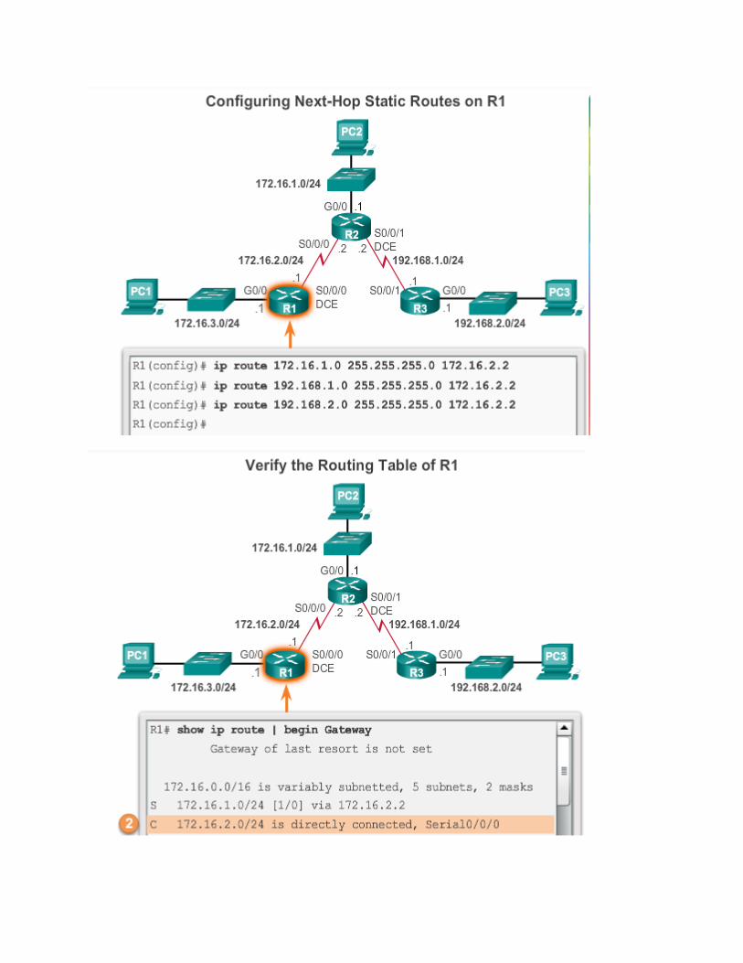
When configuring a static route, another option is to use the exit interface to specify the next-hop
address. In older IOS versions, prior to CEF, this method is used to avoid the recursive lookup
problem.
In Figure 1, three directly connected static routes are configured on R1 using the exit interface.
The routing table for R1 in Figure 2 shows that when a packet is destined for the 192.168.2.0/24
network, R1 looks for a match in the routing table, and finds that it can forward the packet out of
its Serial 0/0/0 interface. No other lookups are required.
Notice how the routing table looks different for the route configured with an exit interface than the
route configured with a recursive entry.
Configuring a directly connected static route with an exit interface allows the routing table to
resolve the exit interface in a single search, instead of two searches. Although the routing table
entry indicates “directly connected”, the administrative distance of the static route is still 1. Only
a directly connected interface can have an administrative distance of 0.
Note: For point-to-point interfaces, you can use static routes that point to the exit interface or to
the next-hop address. For multipoint/broadcast interfaces, it is more suitable to use static routes
that point to a next-hop address.
Use the Syntax Checker in Figures 3 and 4 to configure and verify directly connected static routes
on R2 and R3.
Although static routes that use only an exit interface on point-to-point networks are common, the
use of the default CEF forwarding mechanism makes this practice unnecessary.
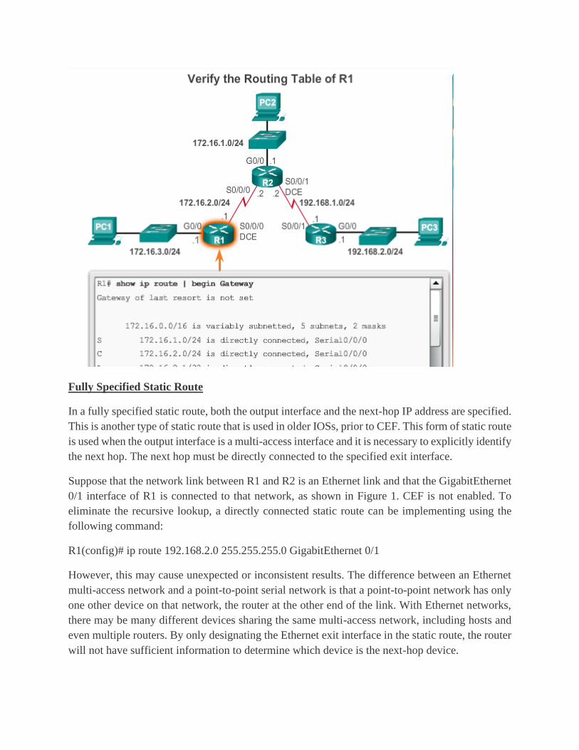
Fully Specified Static Route
In a fully specified static route, both the output interface and the next-hop IP address are specified.
This is another type of static route that is used in older IOSs, prior to CEF. This form of static route
is used when the output interface is a multi-access interface and it is necessary to explicitly identify
the next hop. The next hop must be directly connected to the specified exit interface.
Suppose that the network link between R1 and R2 is an Ethernet link and that the GigabitEthernet
0/1 interface of R1 is connected to that network, as shown in Figure 1. CEF is not enabled. To
eliminate the recursive lookup, a directly connected static route can be implementing using the
following command:
R1(config)# ip route 192.168.2.0 255.255.255.0 GigabitEthernet 0/1
However, this may cause unexpected or inconsistent results. The difference between an Ethernet
multi-access network and a point-to-point serial network is that a point-to-point network has only
one other device on that network, the router at the other end of the link. With Ethernet networks,
there may be many different devices sharing the same multi-access network, including hosts and
even multiple routers. By only designating the Ethernet exit interface in the static route, the router
will not have sufficient information to determine which device is the next-hop device.

R1 knows that the packet needs to be encapsulated in an Ethernet frame and sent out the
GigabitEthernet 0/1 interface. However, R1 does not know the next-hop IPv4 address and therefore
it cannot determine the destination MAC address for the Ethernet frame.
Depending upon the topology and the configurations on other routers, this static route may or may
not work. It is recommended that when the exit interface is an Ethernet network, that a fully
specified static route is used including both the exit interface and the next-hop address.
As shown in Figure 2, when forwarding packets to R2, the exit interface is GigabitEthernet 0/1
and the next-hop IPv4 address is 172.16.2.2.
Note: With the use of CEF, a fully specified static route is no longer necessary. A static route using
a next-hop address should be used.
Use the Syntax Checker in Figure 3 and 4 to configure and verify fully specified static routes on
R2 and R3.
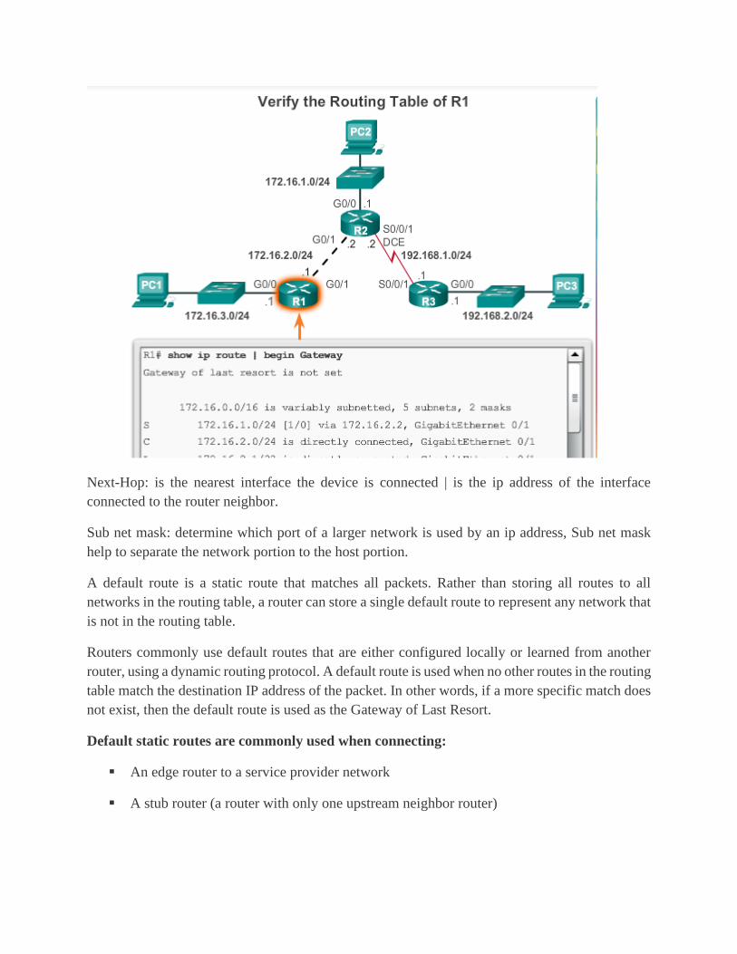
Next-Hop: is the nearest interface the device is connected | is the ip address of the interface
connected to the router neighbor.
Sub net mask: determine which port of a larger network is used by an ip address, Sub net mask
help to separate the network portion to the host portion.
A default route is a static route that matches all packets. Rather than storing all routes to all
networks in the routing table, a router can store a single default route to represent any network that
is not in the routing table.
Routers commonly use default routes that are either configured locally or learned from another
router, using a dynamic routing protocol. A default route is used when no other routes in the routing
table match the destination IP address of the packet. In other words, if a more specific match does
not exist, then the default route is used as the Gateway of Last Resort.
Default static routes are commonly used when connecting:
▪ An edge router to a service provider network
▪ A stub router (a router with only one upstream neighbor router)

As shown in the figure, the command syntax for a default static route is similar to any other static
route, except that the network address is 0.0.0.0 and the subnet mask is 0.0.0.0. The basic command
syntax of a default static route is:
ip route 0.0.0.0 0.0.0.0 { ip-address | exit-intf }
Note: An IPv4 default static route is commonly referred to as a quad-zero route.
Show ip route 192.168.160.0
Show ip route static
Along with ping and traceroute, useful commands to verify static routes include:
▪ show ip route
▪ show ip route static
▪ show ip route network
Figure 1 displays sample output of the show ip route static command. In the example, the output
is filtered using the pipe and begin parameter. The output reflects the use of static routes using the
next-hop address.
Figure 2 displays sample output of the show ip route 192.168.2.1 command.
Figure 3 verifies the ip route configuration in the running configuration.
Use the Syntax Checker in Figure 4 to verify the routing settings of R2.
Use the Syntax Checker in Figure 5 to verify the routing settings of R3.
Dynamic Routing Protocols

Dynamic Routing Protocol Operation
Routing protocols are used to facilitate the exchange of routing information between routers. A
routing protocol is a set of processes, algorithms, and messages that are used to exchange routing
information and populate the routing table with the routing protocol's choice of best paths. The
purpose of dynamic routing protocols includes:
▪ Discovery of remote networks
▪ Maintaining up-to-date routing information
▪ Choosing the best path to destination networks
▪ Ability to find a new best path if the current path is no longer available
The main components of dynamic routing protocols include:
Data structures - Routing protocols typically use tables or databases for its operations. This
information is kept in RAM.
Routing protocol messages - Routing protocols use various types of messages to discover
neighboring routers, exchange routing information, and other tasks to learn and maintain accurate
information about the network.
Algorithm - An algorithm is a finite list of steps used to accomplish a task. Routing protocols use
algorithms for facilitating routing information and for best path determination.
The figure highlights the data structures, routing protocol messages, and routing algorithm used
by EIGRP.
Routing protocols allow routers to dynamically share information about remote networks and
automatically add this information to their own routing tables; see the animation in the figure.
Before identifying the benefits of dynamic routing protocols, consider the reasons why network
professionals use static routing. Dynamic routing certainly has several advantages over static
routing; however, static routing is still used in networks today. In fact, networks typically use a
combination of both static and dynamic routing.
Static routing has several primary uses, including:
Providing ease of routing table maintenance in smaller networks that are not expected to grow
significantly.
Routing to and from a stub network, which is a network with only one default route out and no
knowledge of any remote networks.
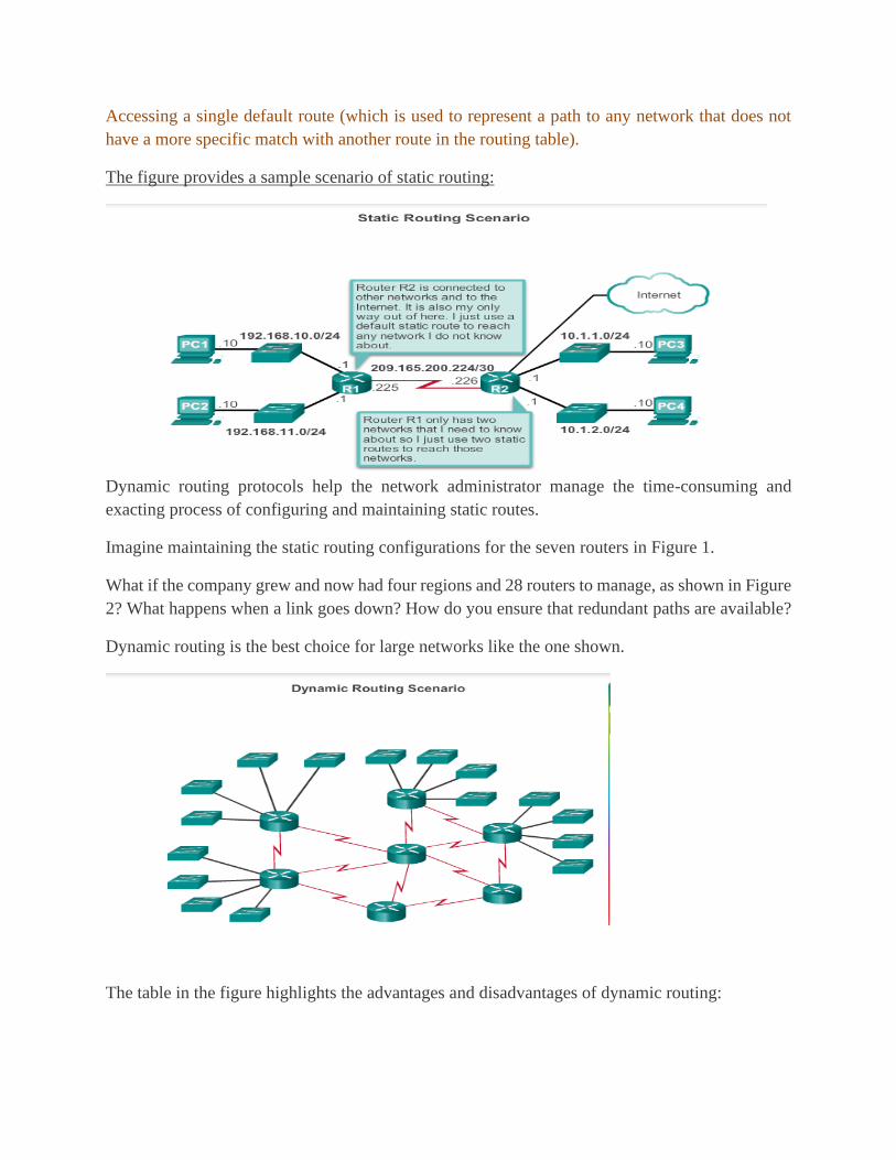
Accessing a single default route (which is used to represent a path to any network that does not
have a more specific match with another route in the routing table).
The figure provides a sample scenario of static routing:
Dynamic routing protocols help the network administrator manage the time-consuming and
exacting process of configuring and maintaining static routes.
Imagine maintaining the static routing configurations for the seven routers in Figure 1.
What if the company grew and now had four regions and 28 routers to manage, as shown in Figure
2? What happens when a link goes down? How do you ensure that redundant paths are available?
Dynamic routing is the best choice for large networks like the one shown.
The table in the figure highlights the advantages and disadvantages of dynamic routing:
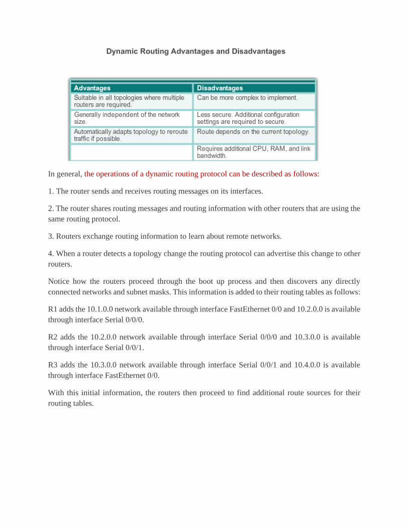
In general, the operations of a dynamic routing protocol can be described as follows:
1. The router sends and receives routing messages on its interfaces.
2. The router shares routing messages and routing information with other routers that are using the
same routing protocol.
3. Routers exchange routing information to learn about remote networks.
4. When a router detects a topology change the routing protocol can advertise this change to other
routers.
Notice how the routers proceed through the boot up process and then discovers any directly
connected networks and subnet masks. This information is added to their routing tables as follows:
R1 adds the 10.1.0.0 network available through interface FastEthernet 0/0 and 10.2.0.0 is available
through interface Serial 0/0/0.
R2 adds the 10.2.0.0 network available through interface Serial 0/0/0 and 10.3.0.0 is available
through interface Serial 0/0/1.
R3 adds the 10.3.0.0 network available through interface Serial 0/0/1 and 10.4.0.0 is available
through interface FastEthernet 0/0.
With this initial information, the routers then proceed to find additional route sources for their
routing tables.
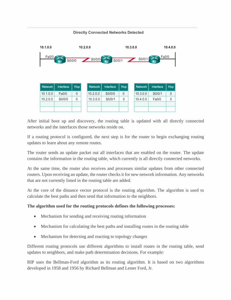
After initial boot up and discovery, the routing table is updated with all directly connected
networks and the interfaces those networks reside on.
If a routing protocol is configured, the next step is for the router to begin exchanging routing
updates to learn about any remote routes.
The router sends an update packet out all interfaces that are enabled on the router. The update
contains the information in the routing table, which currently is all directly connected networks.
At the same time, the router also receives and processes similar updates from other connected
routers. Upon receiving an update, the router checks it for new network information. Any networks
that are not currently listed in the routing table are added.
At the core of the distance vector protocol is the routing algorithm. The algorithm is used to
calculate the best paths and then send that information to the neighbors.
The algorithm used for the routing protocols defines the following processes:
• Mechanism for sending and receiving routing information
• Mechanism for calculating the best paths and installing routes in the routing table
• Mechanism for detecting and reacting to topology changes
Different routing protocols use different algorithms to install routes in the routing table, send
updates to neighbors, and make path determination decisions. For example:
RIP uses the Bellman-Ford algorithm as its routing algorithm. It is based on two algorithms
developed in 1958 and 1956 by Richard Bellman and Lester Ford, Jr.
IGRP and EIGRP use the Diffusing Update Algorithm (DUAL) routing algorithm developed by
Dr. J.J. Garcia-Luna-Aceves at SRI International.
The Routing Information Protocol (RIP) was a first generation routing protocol for IPv4 originally
specified in RFC 1058. It is easy to configure, making it a good choice for small networks.
RIPv1 has the following key characteristics:
• Routing updates are broadcasted (255.255.255.255) every 30 seconds.
• The hop count is used as the metric for path selection.
A hop count greater than 15 hops is deemed infinite (too far). That 15th hop router would not
propagate the routing update to the next router.
In 1993, RIPv1 evolved to a classless routing protocol known as RIP version 2 (RIPv2). RIPv2
introduced the following improvements:
• Classless routing protocol - It supports VLSM (variable length subnet masking) and
CIDR, because it includes the subnet mask in the routing updates.
• Increased efficiency - It forwards updates to multicast address 224.0.0.9, instead of the
broadcast address 255.255.255.255.
• Reduced routing entries - It supports manual route summarization on any interface.
• Secure - It supports an authentication mechanism to secure routing table updates between
neighbors.
RIP updates are encapsulated into a UDP segment, with both source and destination port numbers
set to UDP port 520.
In 1997, the IPv6 enabled version of RIP was released. RIP is based on RIPv2. It still has a 15 hop
limitation and the administrative distance is 120.
Although RIP is rarely used in modern networks, it is useful as a foundation for understanding
basic network routing. For this reason, this section provides a brief overview of how to configure
basic RIP settings and to verify RIPv2.
RIPv2 is used as the dynamic routing protocol. To enable RIP, use the router rip command, as
shown in Figure 3. This command does not directly start the RIP process. Instead, it provides
access to the router configuration mode where the RIP routing settings are configured.
To disable and eliminate RIP, use the no router rip global configuration command. This command
stops the RIP process and erases all existing RIP configurations.
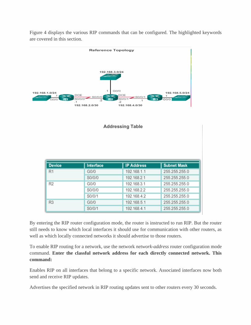
Figure 4 displays the various RIP commands that can be configured. The highlighted keywords
are covered in this section.
By entering the RIP router configuration mode, the router is instructed to run RIP. But the router
still needs to know which local interfaces it should use for communication with other routers, as
well as which locally connected networks it should advertise to those routers.
To enable RIP routing for a network, use the network network-address router configuration mode
command. Enter the classful network address for each directly connected network. This
command:
Enables RIP on all interfaces that belong to a specific network. Associated interfaces now both
send and receive RIP updates.
Advertises the specified network in RIP routing updates sent to other routers every 30 seconds.

Note: If a subnet address is entered, the IOS automatically converts it to the classful network
address. Remember RIPv1 is a classful routing protocol for IPv4. For example, entering the
network 192.168.1.32 command would automatically be converted to network 192.168.1.0 in the
running configuration file. The IOS does not give an error message, but instead corrects the input
and enters the classful network address.
In Figure 1, the network command is used to advertise the R1 directly connected networks.
Use the Syntax Checker in Figure 2 to configure a similar configuration on R2 and R3
The show ip protocols command displays the IPv4 routing protocol settings currently configured
on the router. This output displayed in Figure 1 confirms most RIP parameters including:
1. RIP routing is configured and running on router R1.
2. The values of various timers; for example, the next routing update, is sent by R1 in 16 seconds.
3. The version of RIP configured is currently RIPv1.
4. R1 is currently summarizing at the classful network boundary.
5. The classful networks are advertised by R1. These are the networks that R1 include in its RIP
updates.
6. The RIP neighbors are listed including their next-hop IP address, the associated AD that R2 uses
for updates sent by this neighbor and when the last update was received from this neighbor.
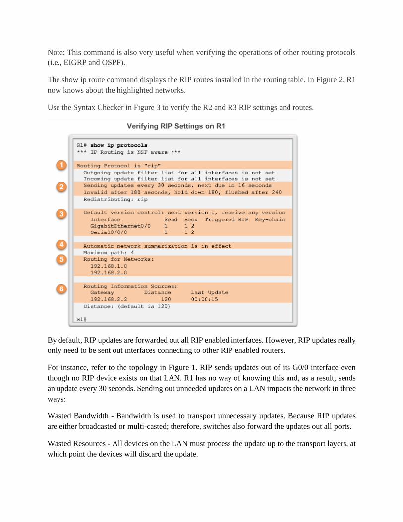
Note: This command is also very useful when verifying the operations of other routing protocols
(i.e., EIGRP and OSPF).
The show ip route command displays the RIP routes installed in the routing table. In Figure 2, R1
now knows about the highlighted networks.
Use the Syntax Checker in Figure 3 to verify the R2 and R3 RIP settings and routes.
By default, RIP updates are forwarded out all RIP enabled interfaces. However, RIP updates really
only need to be sent out interfaces connecting to other RIP enabled routers.
For instance, refer to the topology in Figure 1. RIP sends updates out of its G0/0 interface even
though no RIP device exists on that LAN. R1 has no way of knowing this and, as a result, sends
an update every 30 seconds. Sending out unneeded updates on a LAN impacts the network in three
ways:
Wasted Bandwidth - Bandwidth is used to transport unnecessary updates. Because RIP updates
are either broadcasted or multi-casted; therefore, switches also forward the updates out all ports.
Wasted Resources - All devices on the LAN must process the update up to the transport layers, at
which point the devices will discard the update.

Security Risk - Advertising updates on a broadcast network is a security risk. RIP updates can be
intercepted with packet sniffing software. Routing updates can be modified and sent back to the
router, corrupting the routing table with false metrics that misdirect traffic.
Use the passive-interface router configuration command to prevent the transmission of routing
updates through a router interface, but still allow that network to be advertised to other routers.
The command stops routing updates out the specified interface. However, the network that the
specified interface belongs to is still advertised in routing updates that are sent out other interfaces.
There is no need for R1, R2, and R3 to forward RIP updates out of their LAN interfaces. The
configuration in Figure 2 identifies the R1 G0/0 interface as passive. The show ip protocols
command is then used to verify that the Gigabit Ethernet interface was passive. Notice that the
G0/0 interface is no longer listed as sending or receiving version 2 updates, but instead is now
listed under the Passive Interface(s) section. Also notice that the network 192.168.1.0 is still listed
under Routing for Networks, which means that this network is still included as a route entry in RIP
updates that are sent to R2.
Note: All routing protocols support the passive-interface command.
Use the Syntax Checker in Figure 3 to configure the LAN interface as a passive interface on R2
and R3.
As an alternative, all interfaces can be made passive using the passive-interface default command.
Interfaces that should not be passive can be re-enabled using the no passive-interface command.
The IPv4 link-state routing protocols are shown in the figure below:
Open Shortest Path First (OSPF)

Intermediate System-to-Intermediate System (IS-IS)
The basic functionality and configuration of link-state routing protocols is equally straight-
forward.
Just like RIP and EIGRP, basic OSPF operations can be configured using the:
router ospf process-id global configuration command
network command to advertise networks
All link-state routing protocols apply Dijkstra’s algorithm to calculate the best path route. The
algorithm is commonly referred to as the shortest path first (SPF) algorithm. This algorithm uses
accumulated costs along each path, from source to destination, to determine the total cost of a
route.
In the figure below, each path is labeled with an arbitrary value for cost. The cost of the shortest
path for R2 to send packets to the LAN attached to R3 is 27. Each router determines its own cost
to each destination in the topology. In other words, each router calculates the SPF algorithm and
determines the cost from its own perspective.
Note: The focus of this section is on cost, which is determined by the SPF tree. For this reason, the
graphics throughout this section show the connections of the SPF tree, not the topology. All links
are represented with a solid black line.

The table in Figure 1 displays the shortest path and the accumulated cost to reach the identified
destination networks from the perspective of R1.
The shortest path is not necessarily the path with the least number of hops. For example, look at
the path to the R5 LAN. It might be assumed that R1 would send directly to R4 instead of to R3.
However, the cost to reach R4 directly (22) is higher than the cost to reach R4 through R3 (17).
Observe the shortest path for each router to reach each of the LANs, as shown in Figures 2 to
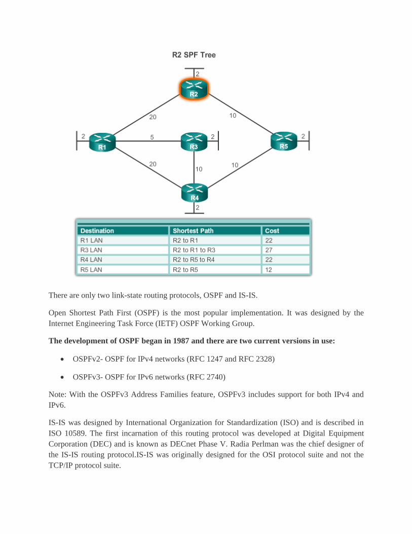
There are only two link-state routing protocols, OSPF and IS-IS.
Open Shortest Path First (OSPF) is the most popular implementation. It was designed by the
Internet Engineering Task Force (IETF) OSPF Working Group.
The development of OSPF began in 1987 and there are two current versions in use:
• OSPFv2- OSPF for IPv4 networks (RFC 1247 and RFC 2328)
• OSPFv3- OSPF for IPv6 networks (RFC 2740)
Note: With the OSPFv3 Address Families feature, OSPFv3 includes support for both IPv4 and
IPv6.
IS-IS was designed by International Organization for Standardization (ISO) and is described in
ISO 10589. The first incarnation of this routing protocol was developed at Digital Equipment
Corporation (DEC) and is known as DECnet Phase V. Radia Perlman was the chief designer of
the IS-IS routing protocol.IS-IS was originally designed for the OSI protocol suite and not the
TCP/IP protocol suite.

OSPF and IS-IS share many similarities and also have many differences. There are many pro-
OSPF and pro-IS-IS factions who discuss and debate the advantages of one routing protocol over
the other. Both routing protocols provide the necessary routing functionality.
Open Shortest Path First (OSPF) is a link-state routing protocol that was developed as a
replacement for the distance vector routing protocol, RIP. RIP was an acceptable routing protocol
in the early days of networking and the Internet. However, RIP's reliance on hop count as the only
metric for determining best route quickly became problematic. Using hop count does not scale
well in larger networks with multiple paths of varying speeds. OSPF has significant advantages
over RIP in that it offers faster convergence and scales to much larger network
implementations.OSPF is a classless routing protocol that uses the concept of areas for scalability.
OSPF features, as shown in Figure 1, include:
Classless - It is classless by design; therefore, it supports VLSM and CIDR.
Efficient - Routing changes trigger routing updates (no periodic updates). It uses the SPF
algorithm to choose the best path.
Fast convergence - It quickly propagates network changes.
Scalable - It works well in small and large network sizes. Routers can be grouped into areas to
support a hierarchical system.
Secure - It supports Message Digest 5 (MD5) authentication. When enabled, OSPF routers only
accept encrypted routing updates from peers with the same pre-shared password.
Administrative distance (AD) is the trustworthiness (or preference) of the route source. OSPF has
a default administrative distance of 110.
All routing protocols share similar components. They all use routing protocol messages to
exchange route information. The messages help build data structures, which are then processed
using a routing algorithm.
The three main components of the OSPF routing protocol include:
Data Structures
OSPF creates and maintains three databases:
Adjacency database - Creates the neighbor table
Link-state database (LSDB) - Creates the topology table
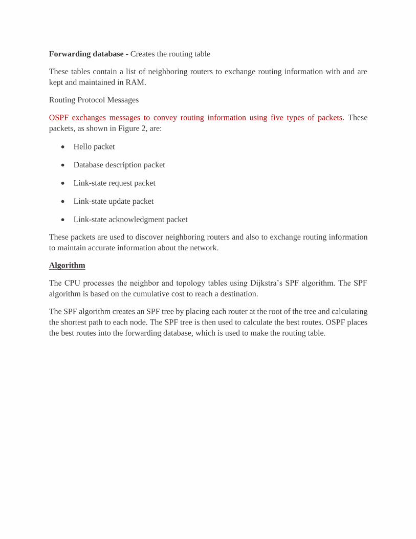
Forwarding database - Creates the routing table
These tables contain a list of neighboring routers to exchange routing information with and are
kept and maintained in RAM.
Routing Protocol Messages
OSPF exchanges messages to convey routing information using five types of packets. These
packets, as shown in Figure 2, are:
• Hello packet
• Database description packet
• Link-state request packet
• Link-state update packet
• Link-state acknowledgment packet
These packets are used to discover neighboring routers and also to exchange routing information
to maintain accurate information about the network.
Algorithm
The CPU processes the neighbor and topology tables using Dijkstra’s SPF algorithm. The SPF
algorithm is based on the cumulative cost to reach a destination.
The SPF algorithm creates an SPF tree by placing each router at the root of the tree and calculating
the shortest path to each node. The SPF tree is then used to calculate the best routes. OSPF places
the best routes into the forwarding database, which is used to make the routing table.

To make OSPF more efficient and scalable, OSPF supports hierarchical routing using areas. An
OSPF area is a group of routers that share the same link-state information in their LSDBs.
OSPF can be implemented in one of two ways:
Single-Area OSPF - In Figure 1, all routers are in one area called the backbone area (area 0).
Multiarea OSPF - In Figure 2, OSPF is implemented using multiple areas, in a hierarchal fashion.
All areas must connect to the backbone area (area 0). Routers interconnecting the areas are referred
to as Area Border Routers (ABR).

OSPF uses link-state packets (LSPs) to establish and maintain neighbor adjacencies and exchange
routing updates.

Configuring Single-Area OSPFv2
OSPF Router ID
Figure 1 is the reference topology for this topic. OSPFv2 is enabled using the router ospf process-
id global configuration mode command. The process-id value represents a number between 1 and
65,535 and is selected by the network administrator. The process-id value is locally significant,
which means that it does not have to be the same value on the other OSPF routers to establish
adjacencies with those neighbors.
Figure 2 provides an example of entering router OSPF configuration mode on R1.

Note: The router ID looks like an IP address, but it is not routable and, therefore, is not included
in the routing table, unless the OSPF routing process chooses an interface (physical or loopback)
that is appropriately defined by a network command.
Use the router-id rid router configuration mode command to manually assign a 32-bit value
expressed as an IPv4 address to a router. An OSPF router identifies itself to other routers using
this router ID.
As shown in Figure 1, R1 is configured with a router ID of 1.1.1.1, R2 with 2.2.2.2, and R3 with
3.3.3.3.
In Figure 2, the router ID 1.1.1.1 is assigned to R1. Use the show ip protocols command to verify
the router ID.
Note: R1 had never been configured with an OSPF router ID. If it had, then the router ID would
have to be modified.
If the router ID is the same on two neighboring routers, the router displays an error message similar
to the one below:
%OSPF-4-DUP_RTRID1: Detected routers with duplicate router ID.
To correct this problem, configure all routers so that they have unique OSPF router IDs.
Use the Syntax Checker in Figure 3 to assign the router ID to R2 and R3.
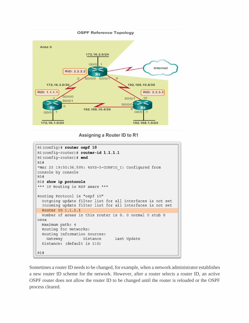
Sometimes a router ID needs to be changed, for example, when a network administrator establishes
a new router ID scheme for the network. However, after a router selects a router ID, an active
OSPF router does not allow the router ID to be changed until the router is reloaded or the OSPF
process cleared.
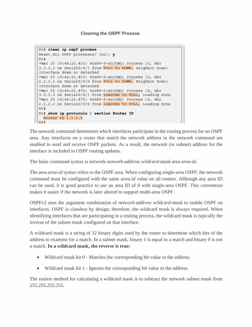
The network command determines which interfaces participate in the routing process for an OSPF
area. Any interfaces on a router that match the network address in the network command are
enabled to send and receive OSPF packets. As a result, the network (or subnet) address for the
interface is included in OSPF routing updates.
The basic command syntax is network network-address wildcard-mask area area-id.
The area area-id syntax refers to the OSPF area. When configuring single-area OSPF, the network
command must be configured with the same area-id value on all routers. Although any area ID
can be used, it is good practice to use an area ID of 0 with single-area OSPF. This convention
makes it easier if the network is later altered to support multi-area OSPF.
OSPFv2 uses the argument combination of network-address wildcard-mask to enable OSPF on
interfaces. OSPF is classless by design; therefore, the wildcard mask is always required. When
identifying interfaces that are participating in a routing process, the wildcard mask is typically the
inverse of the subnet mask configured on that interface.
A wildcard mask is a string of 32 binary digits used by the router to determine which bits of the
address to examine for a match. In a subnet mask, binary 1 is equal to a match and binary 0 is not
a match. In a wildcard mask, the reverse is true:
• Wildcard mask bit 0 - Matches the corresponding bit value in the address.
• Wildcard mask bit 1 - Ignores the corresponding bit value in the address.
The easiest method for calculating a wildcard mask is to subtract the network subnet mask from
255.255.255.255.
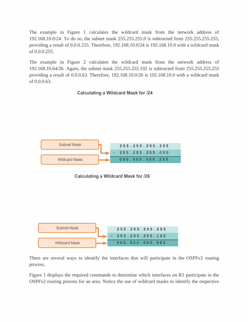
The example in Figure 1 calculates the wildcard mask from the network address of
192.168.10.0/24. To do so, the subnet mask 255.255.255.0 is subtracted from 255.255.255.255,
providing a result of 0.0.0.255. Therefore, 192.168.10.0/24 is 192.168.10.0 with a wildcard mask
of 0.0.0.255.
The example in Figure 2 calculates the wildcard mask from the network address of
192.168.10.64/26. Again, the subnet mask 255.255.255.192 is subtracted from 255.255.255.255
providing a result of 0.0.0.63. Therefore, 192.168.10.0/26 is 192.168.10.0 with a wildcard mask
of 0.0.0.63.
There are several ways to identify the interfaces that will participate in the OSPFv2 routing
process.
Figure 1 displays the required commands to determine which interfaces on R1 participate in the
OSPFv2 routing process for an area. Notice the use of wildcard masks to identify the respective
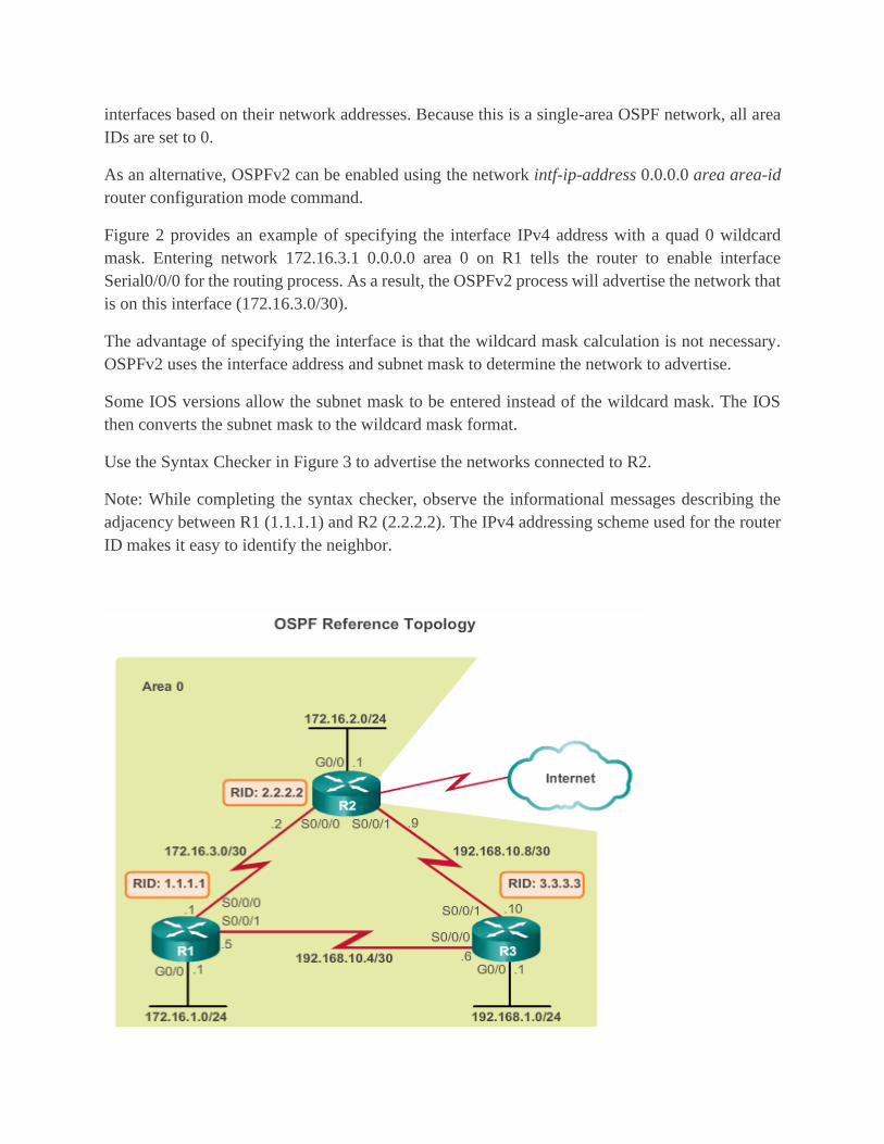
interfaces based on their network addresses. Because this is a single-area OSPF network, all area
IDs are set to 0.
As an alternative, OSPFv2 can be enabled using the network intf-ip-address 0.0.0.0 area area-id
router configuration mode command.
Figure 2 provides an example of specifying the interface IPv4 address with a quad 0 wildcard
mask. Entering network 172.16.3.1 0.0.0.0 area 0 on R1 tells the router to enable interface
Serial0/0/0 for the routing process. As a result, the OSPFv2 process will advertise the network that
is on this interface (172.16.3.0/30).
The advantage of specifying the interface is that the wildcard mask calculation is not necessary.
OSPFv2 uses the interface address and subnet mask to determine the network to advertise.
Some IOS versions allow the subnet mask to be entered instead of the wildcard mask. The IOS
then converts the subnet mask to the wildcard mask format.
Use the Syntax Checker in Figure 3 to advertise the networks connected to R2.
Note: While completing the syntax checker, observe the informational messages describing the
adjacency between R1 (1.1.1.1) and R2 (2.2.2.2). The IPv4 addressing scheme used for the router
ID makes it easy to identify the neighbor.

By default, OSPF messages are forwarded out all OSPF-enabled interfaces. However, these
messages really only need to be sent out interfaces connecting to other OSPF-enabled routers.
Refer to the topology in the figure. OSPF messages are forwarded out of all three routers G0/0
interface even though no OSPF neighbor exists on that LAN. Sending out unneeded messages
on a LAN affects the network in three ways:
Inefficient Use of Bandwidth - Available bandwidth is consumed transporting unnecessary
messages. Messages are multi-casted; therefore, switches are also forwarding the messages out all
ports.
Inefficient Use of Resources - All devices on the LAN must process the message and eventually
discard the message.
Increased Security Risk - Advertising updates on a broadcast network is a security risk. OSPF
messages can be intercepted with packet sniffing software. Routing updates can be modified and
sent back to the router, corrupting the routing table with false metrics that misdirect traffic.
Use the passive-interface router configuration mode command to prevent the transmission of
routing messages through a router interface, but still allow that network to be advertised to other
routers, as shown in Figure 1. Specifically, the command stops routing messages from being sent
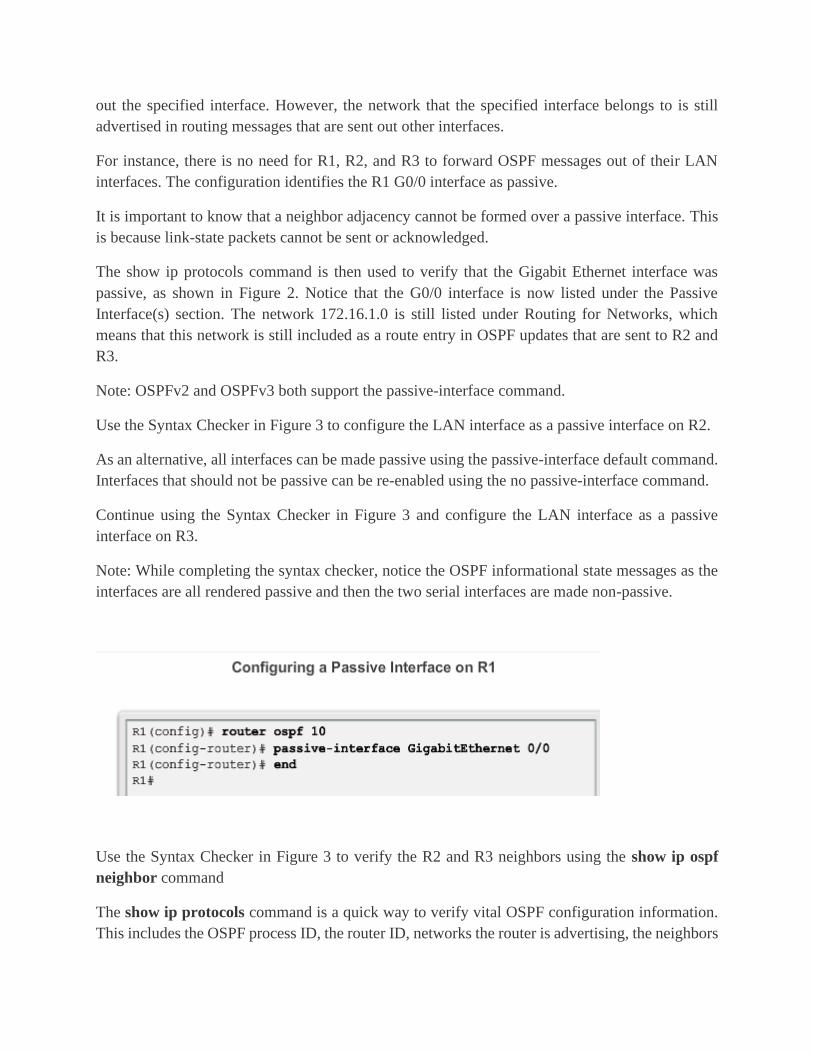
out the specified interface. However, the network that the specified interface belongs to is still
advertised in routing messages that are sent out other interfaces.
For instance, there is no need for R1, R2, and R3 to forward OSPF messages out of their LAN
interfaces. The configuration identifies the R1 G0/0 interface as passive.
It is important to know that a neighbor adjacency cannot be formed over a passive interface. This
is because link-state packets cannot be sent or acknowledged.
The show ip protocols command is then used to verify that the Gigabit Ethernet interface was
passive, as shown in Figure 2. Notice that the G0/0 interface is now listed under the Passive
Interface(s) section. The network 172.16.1.0 is still listed under Routing for Networks, which
means that this network is still included as a route entry in OSPF updates that are sent to R2 and
R3.
Note: OSPFv2 and OSPFv3 both support the passive-interface command.
Use the Syntax Checker in Figure 3 to configure the LAN interface as a passive interface on R2.
As an alternative, all interfaces can be made passive using the passive-interface default command.
Interfaces that should not be passive can be re-enabled using the no passive-interface command.
Continue using the Syntax Checker in Figure 3 and configure the LAN interface as a passive
interface on R3.
Note: While completing the syntax checker, notice the OSPF informational state messages as the
interfaces are all rendered passive and then the two serial interfaces are made non-passive.
Use the Syntax Checker in Figure 3 to verify the R2 and R3 neighbors using the show ip ospf
neighbor command
The show ip protocols command is a quick way to verify vital OSPF configuration information.
This includes the OSPF process ID, the router ID, networks the router is advertising, the neighbors
the router is receiving updates from, and the default administrative distance, which is 110 for
OSPF.
The show ip ospf command can also be used to examine the OSPF process ID and router ID, as
shown in Figure 1. This command displays the OSPF area information and the last time the SPF
algorithm was calculated
The quickest way to verify OSPF interface settings is to use the show ip ospf interface command.
This command provides a detailed list for every OSPF-enabled interface. The command is useful
to determine whether the network statements were correctly composed.
To get a summary of OSPF-enabled interfaces, use the show ip ospf interface brief command, as
shown in Figure 1.
Use the Syntax Checker in Figure 2 to retrieve and view a summary of OSPF-enabled interfaces
on R2 using the show ip ospf interface brief command. Notice that specifying the interface name
as done in the show ip ospf interface serial 0/0/1 command provides detailed OSPF information.
Continue using the Syntax Checker in Figure 2 to get a summary of OSPF-enabled interfaces on
R3 using the show ip ospf interface brief command. Retrieve and view additional information for
the Serial 0/0/0 interface using the show ip ospf interface serial 0/0/0 command.
EIGRP
Introduction
Enhanced Interior Gateway Routing Protocol (EIGRP) is an advanced distance vector routing
protocol developed by Cisco Systems. As the name suggests, EIGRP is an enhancement of another
Cisco routing protocol IGRP (Interior Gateway Routing Protocol). IGRP is an older classful.
EIGRP is a distance vector routing protocol that includes features found in link-state routing
protocols. EIGRP is suited for many different topologies and media. In a well-designed network,
EIGRP can scale to include multiple topologies and can provide extremely quick convergence
times with minimal network traffic.
This chapter introduces EIGRP and provides basic configuration commands to enable it on a Cisco
IOS router. It also explores the operation of the routing protocol and provides more detail on how
EIGRP determines best path.
Classless EIGRP
EIGRP was introduced as a distance vector routing protocol in 1992. It was originally designed to
work as a proprietary protocol on Cisco devices only. In 2013, EIGRP became a multi-vendor
routing protocol, meaning that it can be used by other device vendors in addition to Cisco devices.
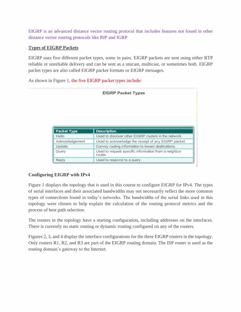
EIGRP is an advanced distance vector routing protocol that includes features not found in other
distance vector routing protocols like RIP and IGRP
Types of EIGRP Packets
EIGRP uses five different packet types, some in pairs. EIGRP packets are sent using either RTP
reliable or unreliable delivery and can be sent as a unicast, multicast, or sometimes both. EIGRP
packet types are also called EIGRP packet formats or EIGRP messages.
As shown in Figure 1, the five EIGRP packet types include:
Configuring EIGRP with IPv4
Figure 1 displays the topology that is used in this course to configure EIGRP for IPv4. The types
of serial interfaces and their associated bandwidths may not necessarily reflect the more common
types of connections found in today’s networks. The bandwidths of the serial links used in this
topology were chosen to help explain the calculation of the routing protocol metrics and the
process of best path selection.
The routers in the topology have a starting configuration, including addresses on the interfaces.
There is currently no static routing or dynamic routing configured on any of the routers.
Figures 2, 3, and 4 display the interface configurations for the three EIGRP routers in the topology.
Only routers R1, R2, and R3 are part of the EIGRP routing domain. The ISP router is used as the
routing domain’s gateway to the Internet.

EIGRP uses the router eigrp autonomous-system command to enable the EIGRP process. The
autonomous system number referred to in the EIGRP configuration is not associated with the
Internet Assigned Numbers Authority (IANA) globally assigned autonomous system numbers
used by external routing protocols
The Cisco IOS includes the processes to enable and configure several different types of dynamic
routing protocols. The router global configuration mode command is used to begin the
configuration of any dynamic routing protocol. The topology shown in Figure 1 is used to
demonstrate this command.
As shown in Figure 2, when followed by a question mark (?), the router global configuration
mode command lists of all the available routing protocols supported by this specific IOS release
running on the router.

The following global configuration mode command is used to enter the router configuration mode
for EIGRP and begin the configuration of the EIGRP process:
Router(config)# router eigrp autonomous-system
The autonomous-system argument can be assigned to any 16-bit value between the number 1 and
65,535. All routers within the EIGRP routing domain must use the same autonomous system
number.
Figure 3 shows the configuration of the EIGRP process on routers R1, R2, and R3. Notice that the
prompt changes from a global configuration mode prompt to router configuration mode.
Note: Both EIGRP and OSPF can support multiple instances of each routing protocol, although
this type of multiple routing protocol implementation is not usually needed or recommended.
The router eigrp autonomous-system command does not start the EIGRP process itself. The router
does not start sending updates. Rather, this command only provides access to configure the EIGRP
settings.
To completely remove the EIGRP routing process from a device, use the no router eigrp
autonomous-system global configuration mode command, which stops the EIGRP process and
removes all existing EIGRP router configurations.

eigrp router-id Command
The eigrp router-id command is used to configure the EIGRP router ID and takes precedence
over any loopback or physical interface IPv4 addresses. The command syntax is:
Router(config)# router eigrp autonomous-system
Router(config-router)# eigrp router-id ipv4-address
Note: The IPv4 address used to indicate the router ID is actually any 32-bit number displayed in
dotted-decimal notation.
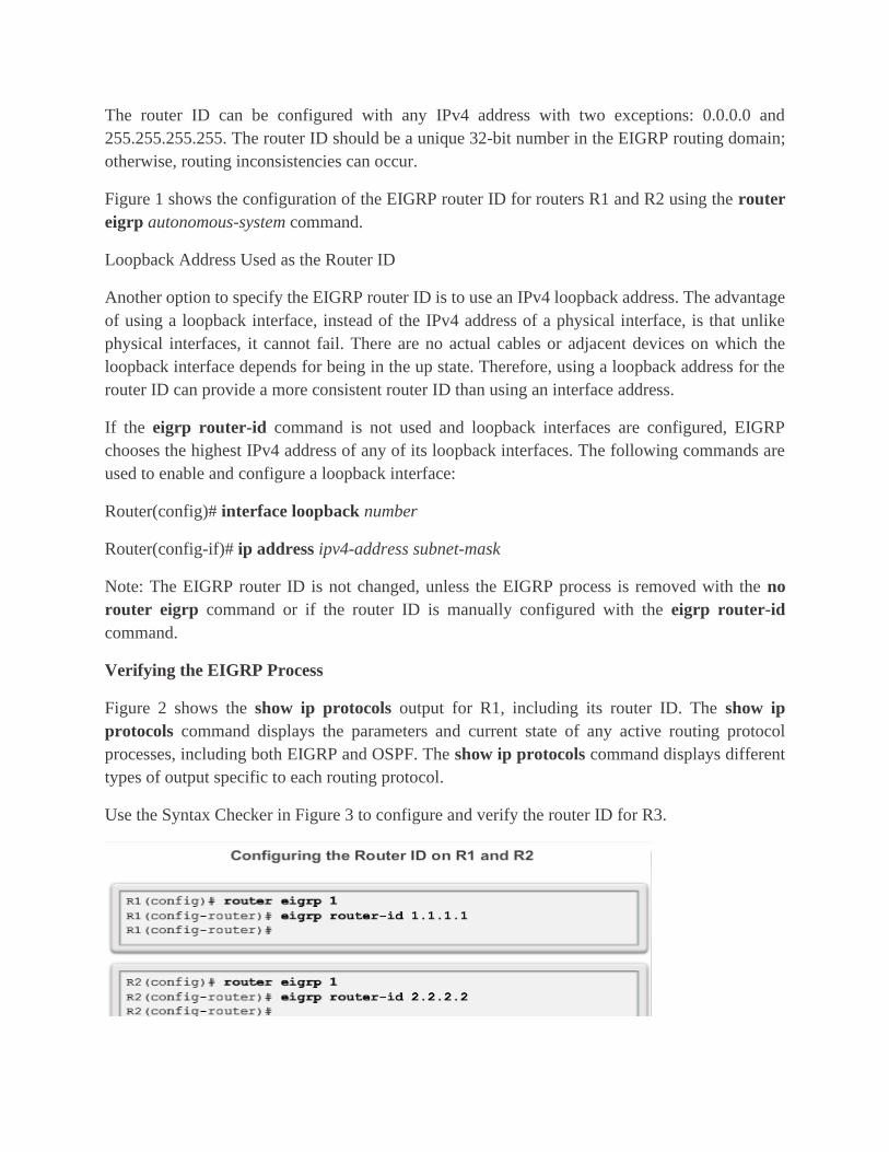
The router ID can be configured with any IPv4 address with two exceptions: 0.0.0.0 and
255.255.255.255. The router ID should be a unique 32-bit number in the EIGRP routing domain;
otherwise, routing inconsistencies can occur.
Figure 1 shows the configuration of the EIGRP router ID for routers R1 and R2 using the router
eigrp autonomous-system command.
Loopback Address Used as the Router ID
Another option to specify the EIGRP router ID is to use an IPv4 loopback address. The advantage
of using a loopback interface, instead of the IPv4 address of a physical interface, is that unlike
physical interfaces, it cannot fail. There are no actual cables or adjacent devices on which the
loopback interface depends for being in the up state. Therefore, using a loopback address for the
router ID can provide a more consistent router ID than using an interface address.
If the eigrp router-id command is not used and loopback interfaces are configured, EIGRP
chooses the highest IPv4 address of any of its loopback interfaces. The following commands are
used to enable and configure a loopback interface:
Router(config)# interface loopback number
Router(config-if)# ip address ipv4-address subnet-mask
Note: The EIGRP router ID is not changed, unless the EIGRP process is removed with the no
router eigrp command or if the router ID is manually configured with the eigrp router-id
command.
Verifying the EIGRP Process
Figure 2 shows the show ip protocols output for R1, including its router ID. The show ip
protocols command displays the parameters and current state of any active routing protocol
processes, including both EIGRP and OSPF. The show ip protocols command displays different
types of output specific to each routing protocol.
Use the Syntax Checker in Figure 3 to configure and verify the router ID for R3.
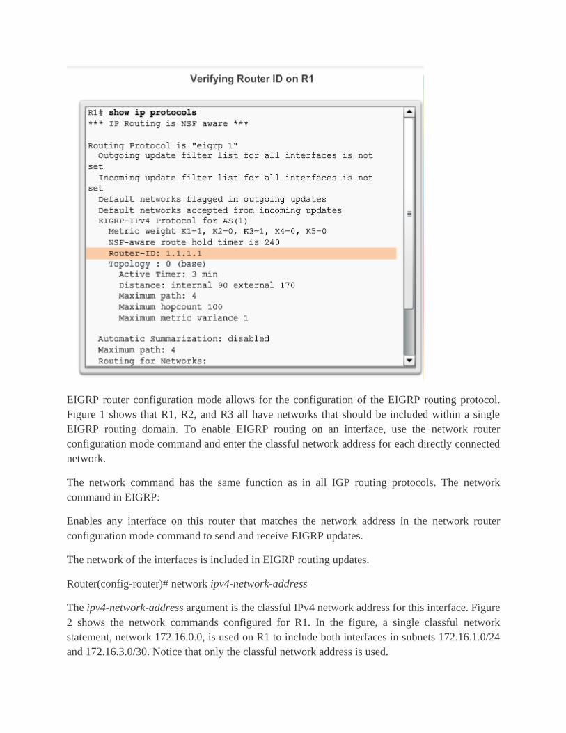
EIGRP router configuration mode allows for the configuration of the EIGRP routing protocol.
Figure 1 shows that R1, R2, and R3 all have networks that should be included within a single
EIGRP routing domain. To enable EIGRP routing on an interface, use the network router
configuration mode command and enter the classful network address for each directly connected
network.
The network command has the same function as in all IGP routing protocols. The network
command in EIGRP:
Enables any interface on this router that matches the network address in the network router
configuration mode command to send and receive EIGRP updates.
The network of the interfaces is included in EIGRP routing updates.
Router(config-router)# network ipv4-network-address
The ipv4-network-address argument is the classful IPv4 network address for this interface. Figure
2 shows the network commands configured for R1. In the figure, a single classful network
statement, network 172.16.0.0, is used on R1 to include both interfaces in subnets 172.16.1.0/24
and 172.16.3.0/30. Notice that only the classful network address is used.
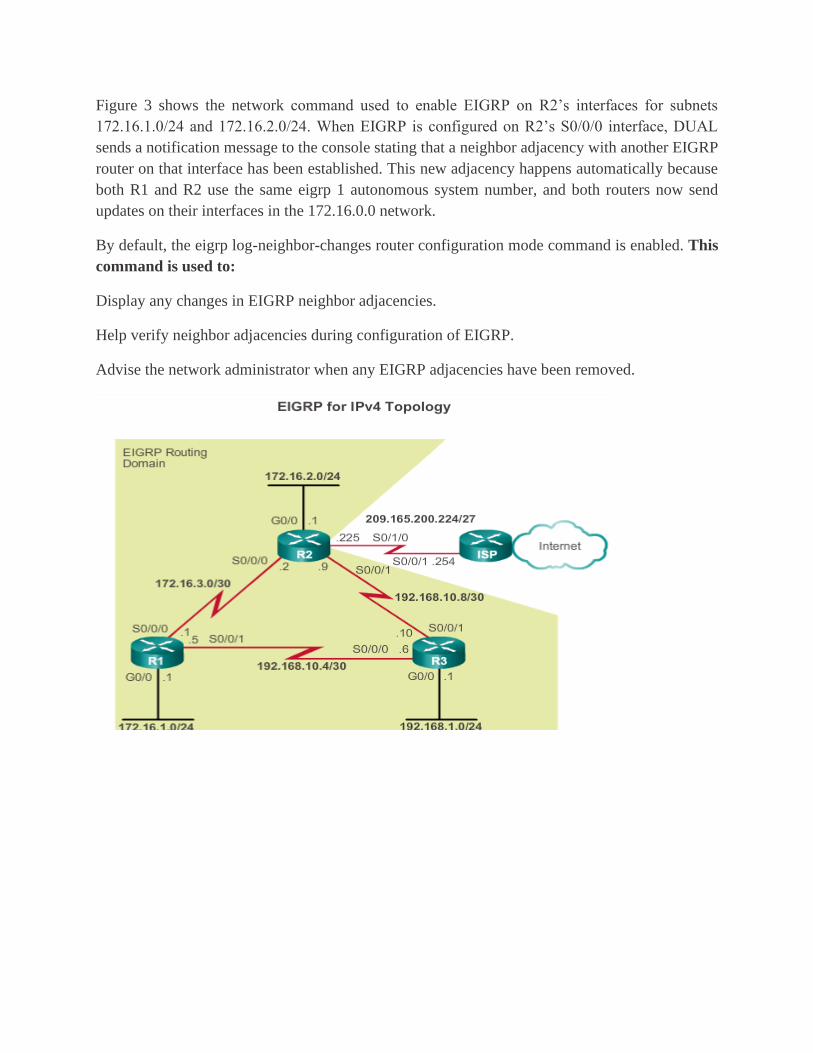
Figure 3 shows the network command used to enable EIGRP on R2’s interfaces for subnets
172.16.1.0/24 and 172.16.2.0/24. When EIGRP is configured on R2’s S0/0/0 interface, DUAL
sends a notification message to the console stating that a neighbor adjacency with another EIGRP
router on that interface has been established. This new adjacency happens automatically because
both R1 and R2 use the same eigrp 1 autonomous system number, and both routers now send
updates on their interfaces in the 172.16.0.0 network.
By default, the eigrp log-neighbor-changes router configuration mode command is enabled. This
command is used to:
Display any changes in EIGRP neighbor adjacencies.
Help verify neighbor adjacencies during configuration of EIGRP.
Advise the network administrator when any EIGRP adjacencies have been removed.
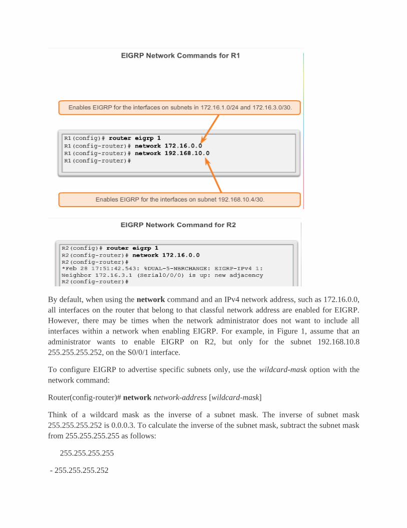
By default, when using the network command and an IPv4 network address, such as 172.16.0.0,
all interfaces on the router that belong to that classful network address are enabled for EIGRP.
However, there may be times when the network administrator does not want to include all
interfaces within a network when enabling EIGRP. For example, in Figure 1, assume that an
administrator wants to enable EIGRP on R2, but only for the subnet 192.168.10.8
255.255.255.252, on the S0/0/1 interface.
To configure EIGRP to advertise specific subnets only, use the wildcard-mask option with the
network command:
Router(config-router)# network network-address [wildcard-mask]
Think of a wildcard mask as the inverse of a subnet mask. The inverse of subnet mask
255.255.255.252 is 0.0.0.3. To calculate the inverse of the subnet mask, subtract the subnet mask
from 255.255.255.255 as follows:
255.255.255.255
- 255.255.255.252

---------------
0. 0. 0. 3 Wildcard mask
Figure 2 continues the EIGRP network configuration of R2. The network 192.168.10.8 0.0.0.3
command specifically enables EIGRP on the S0/0/1 interface, a member of the 192.168.10.8
255.255.255.252 subnet.
Some IOS versions also let you enter the subnet mask instead of a wildcard mask. Figure 3 shows
an example of configuring the same S0/0/1 interface on R2, but this time using a subnet mask in
the network command. However, if the subnet mask is used, the IOS converts the command to
the wildcard-mask format within the configuration. This is verified in the show running-config
output in Figure 3.
Before EIGRP can send or receive any updates, routers must establish adjacencies with their
neighbors. EIGRP routers establish adjacencies with neighbor routers by exchanging EIGRP Hello
packets. Use the show ip eigrp neighbors command to view the neighbor table and verify that
EIGRP has established an adjacency with its neighbors. The show ip eigrp neighbors command
output includes:
H column - Lists the neighbors in the order that they were learned.
Address - IPv4 address of the neighbor.
Interface - Local interface on which this Hello packet was received.
Hold - Current hold time. When a Hello packet is received, this value is reset to the maximum
hold time for that interface, and then counts down to zero. If zero is reached, the neighbor is
considered down.
Uptime - Amount of time since this neighbor was added to the neighbor table.
Smooth Round Trip Timer (SRTT) and Retransmission Timeout (RTO) - Used by RTP to
manage reliable EIGRP packets.
Queue Count - Should always be zero. If more than zero, then EIGRP packets wait to be sent.
Sequence Number - Used to track updates, queries, and reply packets.
The show ip eigrp neighbors command is very useful for verifying and troubleshooting EIGRP. If
a neighbor is not listed after adjacencies have been established with a router’s neighbors, check
the local interface to ensure it is activated with the show ip interface brief command. If the interface
is active, try pinging the IPv4 address of the neighbor. If the ping fails, it means that the neighbor
interface is down and must be activated. If the ping is successful and EIGRP still does not see
the router as a neighbor, examine the following configurations:

Are both routers configured with the same EIGRP autonomous system number?
Is the directly connected network included in the EIGRP network statements?

ASSIGNMENTS1(Choose the correct answer) /6 mark.
1. A protocol that is used to assign automatically IP address to host: /1 mark.
A. ICMP(Internet Control Message
Protocol)
B. DHCP (Dynamic Host Configuration
Protocol)
C. TCP(Transmission Control Protocol)
D. IP (Internet Protocol)
2. Which of the following is Class C IP address? /1 mark.
A. 10.10.14.118
B. 135.23.112.57
C. 191.200.199.199
D. 204.67.118.154
3. Which of the following host addresses is a member of private ip addresses? /1 mark.
A. 10.172.13.6
B. 191.168.23.252
C. 198.234.12.95
D. 212.193.48.254
4. Most wired LAN networks use Ethernet cables to transfer data between connected Computers.
/1 mark.
A. True
B. False
5. A MAN(Metropolitan Area Network) covers a very large area, such as an entire country or the
entire world. /1 mark.
A. True
B. False
6. Which command displays the ip address, subnet mask and default gateway for the end device
or node on the network? /1 mark.
A. Show ip route
B. Ping
C. Ipconfig
D. Ipconfig /release

ASSIGNMENTS2(answer all questions) /40 marks
1. PDU (Protocol Data Unit) identifies the format of the data in the first 4 OSI model layers. Then
what is the DPU for each of the following layer: /8 marks
a. Physical layer: ……………….
b. Data link layer: ………………
c. Network layer: ………………
d. Transport layer: ……………..
2. What is the main difference between: /2 marks
a. a route and a switch
3. Refer to the network structure below with the network address of 192.168.1.0/24. Answer
following questions regarding router configuration.
(a) What is the subnet mask of the network that Router is connecting to? /2 mark
(b) Assign IP addresses and default gateway for the Hosts PC-1 and PC-2 by filling the following table:
/2 marks
Host IP address Default gateway
PC-1
PC-2
(c) How do you check the connectivity of the two computers on the given network? /1 mark
(d) Configure Interface Fa0/1 of router according to the given network address /4 marks
(e) Write a router command that displays IP address of the interface Fa0/1 /1 mark
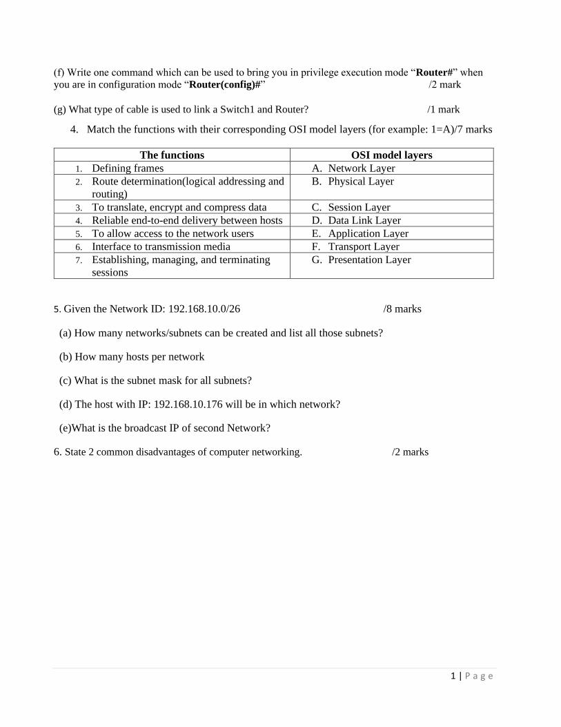
1 | P a g e
(f) Write one command which can be used to bring you in privilege execution mode “Router#” when
you are in configuration mode “Router(config)#” /2 mark
(g) What type of cable is used to link a Switch1 and Router? /1 mark
4. Match the functions with their corresponding OSI model layers (for example: 1=A)/7 marks
The functions OSI model layers
1. Defining frames A. Network Layer
2. Route determination(logical addressing and
routing) B. Physical Layer
3. To translate, encrypt and compress data C. Session Layer
4. Reliable end-to-end delivery between hosts D. Data Link Layer
5. To allow access to the network users E. Application Layer
6. Interface to transmission media F. Transport Layer
7. Establishing, managing, and terminating
sessions G. Presentation Layer
5. Given the Network ID: 192.168.10.0/26 /8 marks
(a) How many networks/subnets can be created and list all those subnets?
(b) How many hosts per network
(c) What is the subnet mask for all subnets?
(d) The host with IP: 192.168.10.176 will be in which network?
(e)What is the broadcast IP of second Network?
6. State 2 common disadvantages of computer networking. /2 marks