Embed Size (px)
Citation preview
1
Extension module extends function of PLC base unit. It offers function like: IO point extension, logic processing, data calculation, analog-digital conversion, and so on.
Module models
So far, there are extension module as shown in Table 1.1. Model Description
Module of FGs series
FGs-E16R 16 channels relay type digital output module
FGs-E16T 16 channels transistor type digital output module
FGs-E16X 16 channels digital input module
FGs-E8X8R 8 channels digital input, 8 channels relay type digital output module
FGs-E8X8T 8 channels digital input, 8 channels transistor type digital output module
FGs-E4AI2AO 4 channels analog input, 2 channels analog output module
FGs-E8AI 8 channels analog input module
FGs-E4TC 4 channels temperature measuring module
Module of FGR series
FGR-E12R 12 channels relay type digital output module
FGR-E16T 16 channels transistor type digital output module
FGR-E16X 16 channels digital input module
FGR-E8X8R 8 channels digital input, 8 channels relay type digital output module
FGR-E8X8T 8 channels digital input, 8 channels transistor type digital output module
FGR-E4AI 4 channels analog input module
FGR-E8AI 8 channels analog input module
FGR-E4AI2AO 4 channels analog input, 2 channels analog output module
FGR-E2AO 2 channels analog output module
FGR-E4TC 4 channels temperature measuring module
Table 1. 1
Number of digital input/output module channels is octonary. (For instance: X1000~X1007, X1010~X1017)
Number of analog input/output module points is decimal, and each module occupies 4 or 8 data registers. (For instance: AI100~AI103, AI110~AI113)
The FGs and FGm series PLC base unit supports at most 8 FGs-E extension modules regardless of their types.
FGR series PLC base unit supports at most 1 A-E attachment and 3 FGR-E extension modules.
A-E attachment can be regarded as part of PLC base unit, it extends digital IO points and the number follows close with PLC base unit. (For instance: X0010~X0017, Y0010~Y0017)
2
Configuration in SamSoar II
Configuration should be completed by upper software SamSoar II before using extension module. The following shows procedures to configure the FGs-E and FGR-E extension modules.
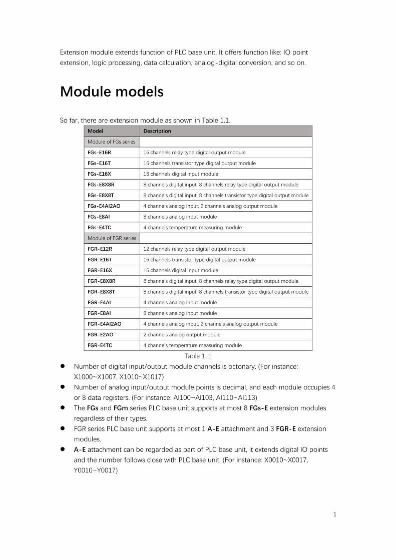
1. Open the SamSoar II, Click [Project]→[PLC parameter setting] or icon , select
corresponding PLC model, take FGRE-C8X8T as example.
Figure 2. 1
2. Click [Extension Module] Tab, enter setting page.
Figure 2. 2
3. Tick the option [Use Extension Module] to enable the setting.
3
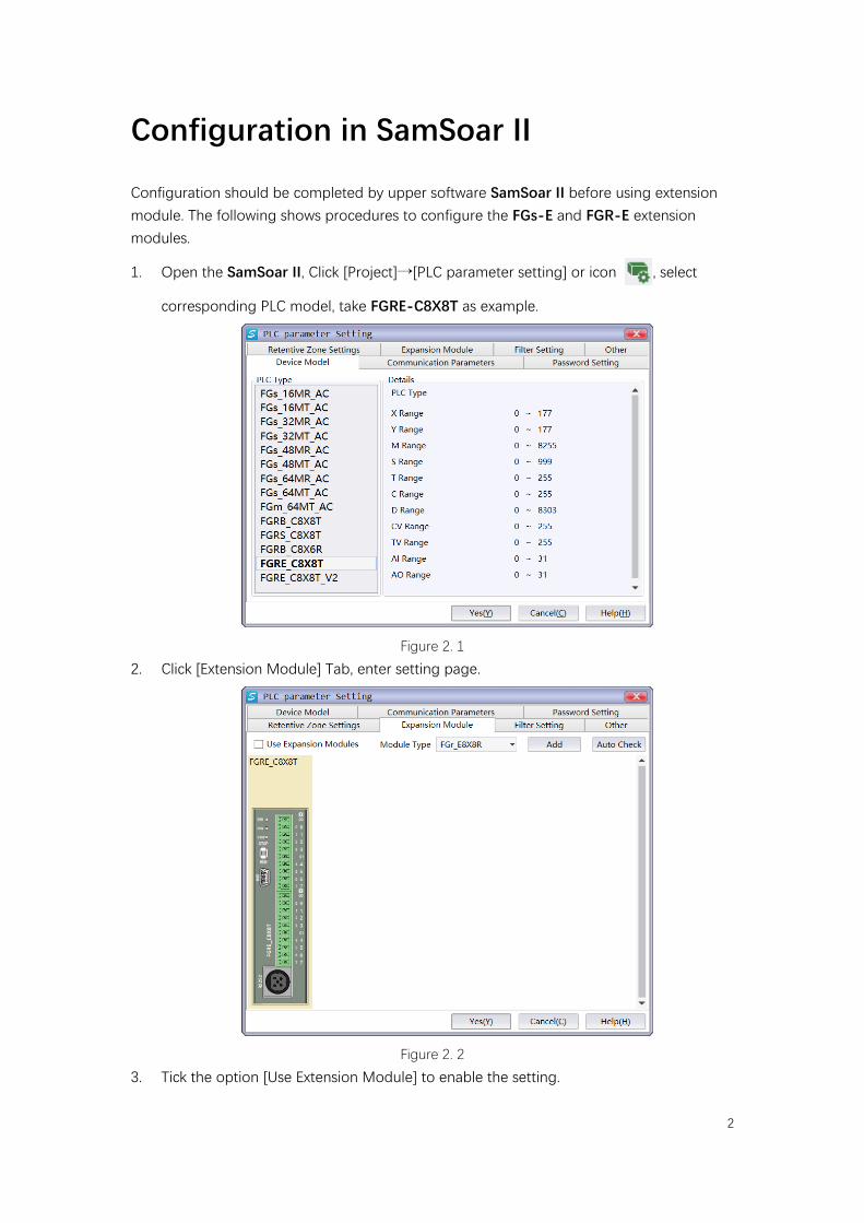
Figure 2. 3
Select module type and tick [Enabled] to enable it. User can also check the module automatically by click [Auto check] when PLC is in communication with SamSoar II. PLC should be in STOP state during checking, and after checking, the manual added modules will be replaced according to actual checked case.
Figure 2. 4
Figure 2. 5
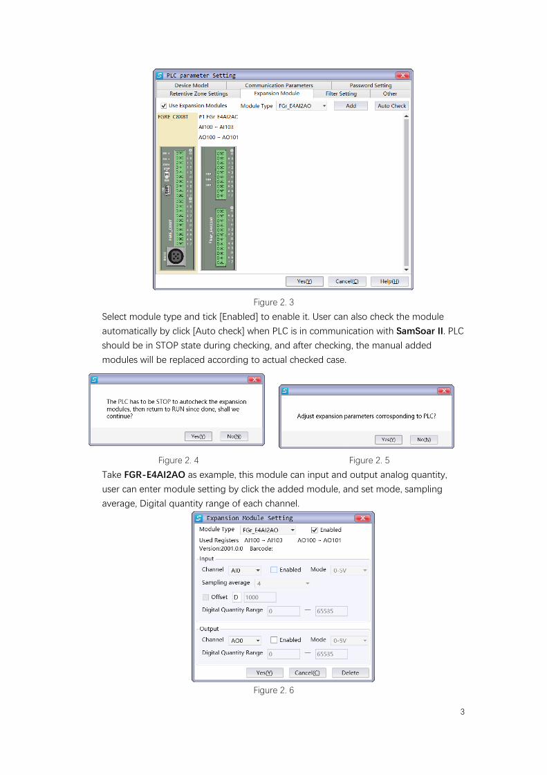
Take FGR-E4AI2AO as example, this module can input and output analog quantity, user can enter module setting by click the added module, and set mode, sampling average, Digital quantity range of each channel.
Figure 2. 6
4
Digital input/output module
Digital input/output module include FGs-E16R, FGs-E16T, FGs-E16X, FGs-E8X8R, FGs-E8X8T, FGR-E12R, FGR-E16T, FGR-E16X, FGR-E8X8R, FGR-E8X8T. This chapter takes FGs-E8X8T as example to introduce usage of digital input/output module.
Module specification
FGs-E8X8T extends input and output terminal of PLC base unit, the usage is same as ordinary inputs/outputs (not high-speed) of PLC base unit. Module specification refers to following table (details of more models refer to hardware manual).
Input voltage 24V±20%/DC
Output voltage 6~30V/DC
Inductive load maximum 80W
Resistive load maximum 0.3A
Table 3. 1
Wring of inputs depends on the if the input is drain type or source type. Terminal number of input and output are octal. 4 common ends (COM1~COM3) of outputs is shorted, so they take same effect.
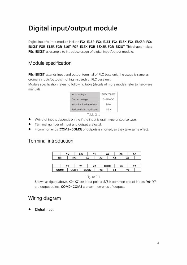
Terminal introduction
Figure 3. 1
Shown as figure above, X0~X7 are input points, S/S is common end of inputs, Y0~Y7 are output points, COM0~COM3 are common ends of outputs.
Wiring diagram
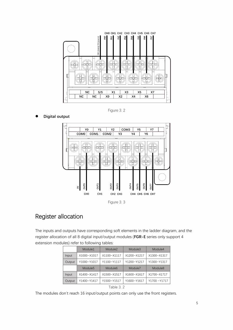
Digital input
5
Figure 3. 2
Digital output
Figure 3. 3
Register allocation
The inputs and outputs have corresponding soft elements in the ladder diagram, and the register allocation of all 8 digital input/output modules (FGR-E series only support 4 extension modules) refer to following tables:
Module1 Module2 Module3 Module4
Input X1000~X1017 X1100~X1117 X1200~X1217 X1300~X1317
Output Y1000~Y1017 Y1100~Y1117 Y1200~Y1217 Y1300~Y1317
Module5 Module6 Module7 Module8
Input X1400~X1417 X1500~X1517 X1600~X1617 X1700~X1717
Output Y1400~Y1417 Y1500~Y1517 Y1600~Y1617 Y1700 ~Y1717
Table 3. 2
The modules don’t reach 16 input/output points can only use the front registers.
6
Analog input/output module
Analog input/output module include FGs-E4AI2AO, FGs-E8AI, FGR-E4AI, FGR-E8AI, FGR-E4AI2AO, FGR-E2AO. This chapter takes FGs-E4AI2AO module as example to introduce usage of analog input/output module.
Module specification
FGs-E4AI2AO module converts analog quantity inputs (voltage/current) of 4 input points into digital quantities, and transfer them to PLC base unit. Additionally, this module can also output analog quantities form the 2 output points. Module specification refers to following table (details of more models refer to hardware manual).
Voltage input Current input Voltage output Current output
Analog quantity range 0~5V, 0~10V 4~20mA 0~5V, 0~10V 4~20mA
Input maximum ±15V 40mA - -
Resolution 1/4095 (12-bit) 1/65535 (16-bit)
Accuracy ±5‰ ±5‰
Conversion rate 1ms/ch 1ms/ch
Analog output power supply 24V±10%/DC, 100mA
Table 4. 1
Input and output have different modes: 0~5V voltage mode, 0~10V voltage mode, and 4~20mA current mode.
The input has 12-bit resolution, and output has 16-bit resolution. The power supply of analog part and digital part is separate. User can set digital range (high limit and low limit) of the conversion, the analog
quantity will scale linearly according to the range.
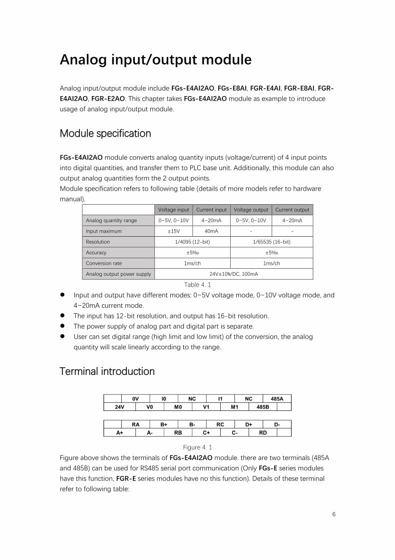
Terminal introduction
Figure 4. 1
Figure above shows the terminals of FGs-E4AI2AO module. there are two terminals (485A and 485B) can be used for RS485 serial port communication (Only FGs-E series modules have this function, FGR-E series modules have no this function). Details of these terminal refer to following table:
7
Channel Terminal Description
Analog quantity Input
Input CH0
A+ Anode of input channel 0
RA Connect to A+ under current mode
A- Cathode of input channel 0
Input CH1
B+ Anode of input channel 1
RB Connect to B+ under current mode
B- Cathode of input channel 1
Input CH2
C+ Anode of input channel 2
RC Connect to C+ under current mode
C- Cathode of input channel 2
Input CH3
D+ Anode of input channel 3
RD Connect to D+ under current mode
D- Cathode of input channel 3
Analog quantity output
Output CH0
V0 Voltage output anode of output channel 0
I0 Current output anode of output channel 0
M0 Cathode of output channel 0
Output CH1
V1 Voltage output anode of output channel 1
I1 Current output anode of output channel 1
M1 Cathode of output channel 1
RS485 communication - 485A RS485+
- 485B RS485-
Table 4. 2
Wiring diagram
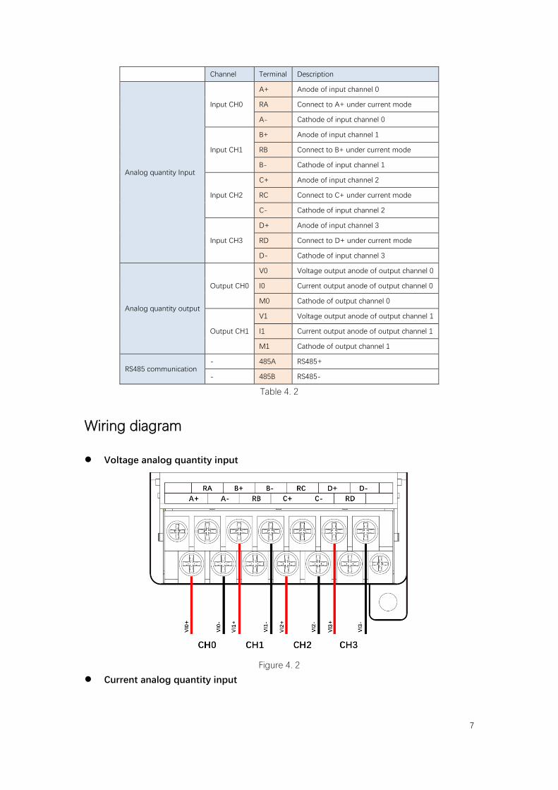
Voltage analog quantity input
Figure 4. 2
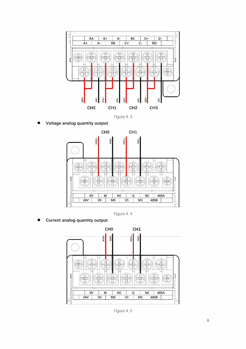
Current analog quantity input
8
Figure 4. 3
Voltage analog quantity output
Figure 4. 4
Current analog quantity output
Figure 4. 5
9
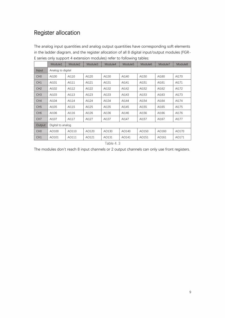
Register allocation
The analog input quantities and analog output quantities have corresponding soft elements in the ladder diagram, and the register allocation of all 8 digital input/output modules (FGR-E series only support 4 extension modules) refer to following tables:
Module1 Module2 Module3 Module4 Module5 Module6 Module7 Module8
Input Analog to digital
CH0 AI100 AI110 AI120 AI130 AI140 AI150 AI160 AI170
CH1 AI101 AI111 AI121 AI131 AI141 AI151 AI161 AI171
CH2 AI102 AI112 AI122 AI132 AI142 AI152 AI162 AI172
CH3 AI103 AI113 AI123 AI133 AI143 AI153 AI163 AI173
CH4 AI104 AI114 AI124 AI134 AI144 AI154 AI164 AI174
CH5 AI105 AI115 AI125 AI135 AI145 AI155 AI165 AI175
CH6 AI106 AI116 AI126 AI136 AI146 AI156 AI166 AI176
CH7 AI107 AI117 AI127 AI137 AI147 AI157 AI167 AI177
Output Digital to analog
CH0 AO100 AO110 AO120 AO130 AO140 AO150 AO160 AO170
CH1 AO101 AO111 AO121 AO131 AO141 AO151 AO161 AO171
Table 4. 3
The modules don’t reach 8 input channels or 2 output channels can only use front registers.
10
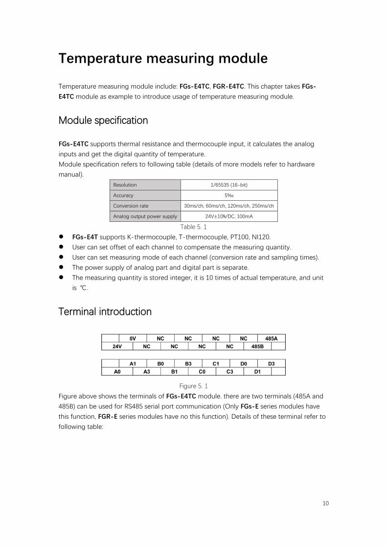
Temperature measuring module
Temperature measuring module include: FGs-E4TC, FGR-E4TC. This chapter takes FGs-E4TC module as example to introduce usage of temperature measuring module.
Module specification
FGs-E4TC supports thermal resistance and thermocouple input, it calculates the analog inputs and get the digital quantity of temperature. Module specification refers to following table (details of more models refer to hardware manual).
Resolution 1/65535 (16-bit)
Accuracy 5‰
Conversion rate 30ms/ch, 60ms/ch, 120ms/ch, 250ms/ch
Analog output power supply 24V±10%/DC, 100mA
Table 5. 1
FGs-E4T supports K-thermocouple, T-thermocouple, PT100, NI120. User can set offset of each channel to compensate the measuring quantity. User can set measuring mode of each channel (conversion rate and sampling times). The power supply of analog part and digital part is separate. The measuring quantity is stored integer, it is 10 times of actual temperature, and unit
is ℃.
Terminal introduction
Figure 5. 1
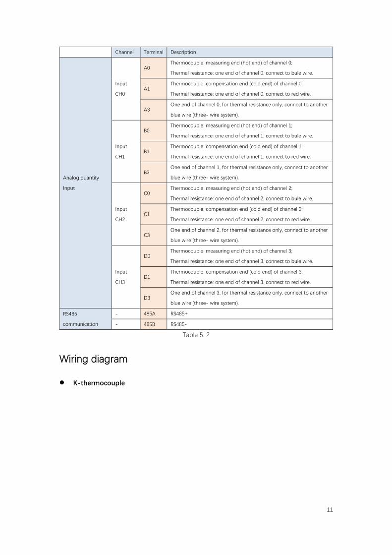
Figure above shows the terminals of FGs-E4TC module. there are two terminals (485A and 485B) can be used for RS485 serial port communication (Only FGs-E series modules have this function, FGR-E series modules have no this function). Details of these terminal refer to following table:
11
Channel Terminal Description
Analog quantity
Input
Input
CH0
A0 Thermocouple: measuring end (hot end) of channel 0;
Thermal resistance: one end of channel 0, connect to bule wire.
A1 Thermocouple: compensation end (cold end) of channel 0;
Thermal resistance: one end of channel 0, connect to red wire.
A3 One end of channel 0, for thermal resistance only, connect to another
blue wire (three- wire system).
Input
CH1
B0 Thermocouple: measuring end (hot end) of channel 1;
Thermal resistance: one end of channel 1, connect to bule wire.
B1 Thermocouple: compensation end (cold end) of channel 1;
Thermal resistance: one end of channel 1, connect to red wire.
B3 One end of channel 1, for thermal resistance only, connect to another
blue wire (three- wire system).
Input
CH2
C0 Thermocouple: measuring end (hot end) of channel 2;
Thermal resistance: one end of channel 2, connect to bule wire.
C1 Thermocouple: compensation end (cold end) of channel 2;
Thermal resistance: one end of channel 2, connect to red wire.
C3 One end of channel 2, for thermal resistance only, connect to another
blue wire (three- wire system).
Input
CH3
D0 Thermocouple: measuring end (hot end) of channel 3;
Thermal resistance: one end of channel 3, connect to bule wire.
D1 Thermocouple: compensation end (cold end) of channel 3;
Thermal resistance: one end of channel 3, connect to red wire.
D3 One end of channel 3, for thermal resistance only, connect to another
blue wire (three- wire system).
RS485
communication
- 485A RS485+
- 485B RS485-
Table 5. 2
Wiring diagram
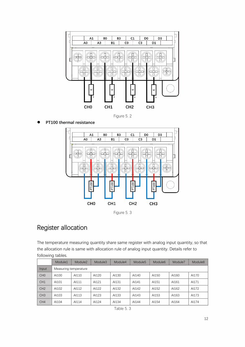
K-thermocouple
12
Figure 5. 2
PT100 thermal resistance
Figure 5. 3
Register allocation
The temperature measuring quantity share same register with analog input quantity, so that the allocation rule is same with allocation rule of analog input quantity. Details refer to following tables.
Module1 Module2 Module3 Module4 Module5 Module6 Module7 Module8
Input Measuring temperature
CH0 AI100 AI110 AI120 AI130 AI140 AI150 AI160 AI170
CH1 AI101 AI111 AI121 AI131 AI141 AI151 AI161 AI171
CH2 AI102 AI112 AI122 AI132 AI142 AI152 AI162 AI172
CH3 AI103 AI113 AI123 AI133 AI143 AI153 AI163 AI173
CH4 AI104 AI114 AI124 AI134 AI144 AI154 AI164 AI174
Table 5. 3
13
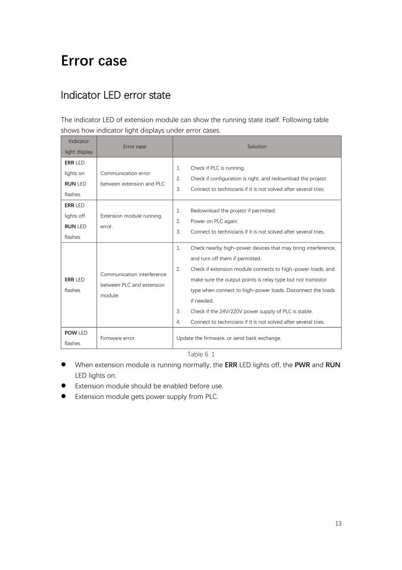
Error case
Indicator LED error state
The indicator LED of extension module can show the running state itself. Following table shows how indicator light displays under error cases.
Indicator
light display Error case Solution
ERR LED
lights on
RUN LED
flashes
Communication error
between extension and PLC.
1. Check if PLC is running.
2. Check if configuration is right, and redownload the project.
3. Connect to technicians if it is not solved after several tries.
ERR LED
lights off
RUN LED
flashes
Extension module running
error.
1. Redownload the project if permitted.
2. Power on PLC again.
3. Connect to technicians if it is not solved after several tries.
ERR LED
flashes
Communication interference
between PLC and extension
module.
1. Check nearby high-power devices that may bring interference,
and turn off them if permitted.
2. Check if extension module connects to high-power loads, and
make sure the output points is relay type but not transistor
type when connect to high-power loads. Disconnect the loads
if needed.
3. Check if the 24V/220V power supply of PLC is stable.
4. Connect to technicians if it is not solved after several tries.
POW LED
flashes Firmware error. Update the firmware, or send back exchange.
Table 6. 1
When extension module is running normally, the ERR LED lights off, the PWR and RUN LED lights on.
Extension module should be enabled before use. Extension module gets power supply from PLC.
14
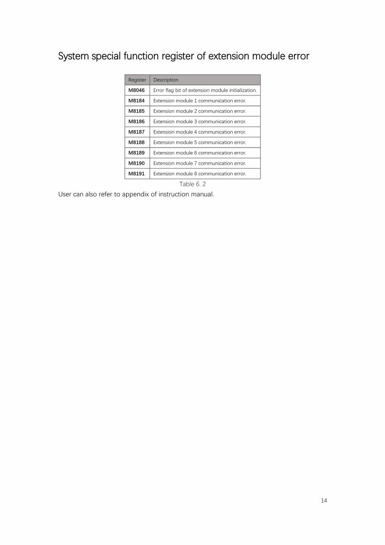
System special function register of extension module error
Register Description
M8046 Error flag bit of extension module initialization.
M8184 Extension module 1 communication error.
M8185 Extension module 2 communication error.
M8186 Extension module 3 communication error.
M8187 Extension module 4 communication error.
M8188 Extension module 5 communication error.
M8189 Extension module 6 communication error.
M8190 Extension module 7 communication error.
M8191 Extension module 8 communication error.
Table 6. 2
User can also refer to appendix of instruction manual.