Embed Size (px)
Citation preview

Module L:Module L:More Rock Mechanics More Rock Mechanics
Issues in Drilling Issues in Drilling
Argentina SPE 2005 Course on Earth Stresses and Drilling Rock Mechanics
Maurice B. DusseaultUniversity of Waterloo and Geomec a.s.

““Predicting” Onset of InstabilityPredicting” Onset of Instability
Now, we have methods of estimating in situ stress conditions
Also, we have methods of measuring or estimating strength
Furthermore, we have methods of calculating stresses around a circular opening, subject to several assumptions…
Putting this together allows prediction of shearing initiation on the borehole wall
…An estimate of “breakouts initiation”

Linear Poroelastic Borehole Linear Poroelastic Borehole Model…Model… Eqn: Where:
pw]cr critical wellbore pressure, shear initiation
pi pressure just inside the borehole wall
σ1, σ3 largest, smallest ppl σ in borehole planeA = α(1-2)/(1-) ( = Poisson’s ratio)α Biot’s coefficient (1.0 for soft rocks)N friction coefficient = (1 + sin’)/(1 - sin’) UCS, Unconfined Compressive Strength,
friction angle (MC yield criterion) Δp “drawdown” = pi - po
1N
p)1N(UCSpA3]p i31crw

Discussion of ParametersDiscussion of Parameters
pw – pi is support pressure
Usually, we ignore effects of “α”, except in low porosity, stiff shales (E > 30-40 GPa)
UCS and N are equivalent to the c’, ’ of the linear MC yield criterion for shear
Poisson’s ratio for shales, 0.25 to 0.35 σ1, σ3 are computed using equations
converting 3-D stress to stresses in the plane of the borehole (90° to hole axis)
pw
pi
po
radius - r

Control Parameters in DrillingControl Parameters in Drilling Mud weight, mud rheological properties,
the geochemistry of the filtrate, cake quality, mud type (WBM, OBM, foam, etc.)
LCM content, type and gradation Tripping and connection practices:
Surging (run-in), swabbing (pull-out) pressures Drilling parameters:
ROP, bit type… Hydraulics and hole cleaning ECD (BHA characteristics, mud properties) Well trajectory, and maybe a few others

Defining Limits in Our Well PlanDefining Limits in Our Well Plan
Predicted MW for onset of unmanageable sloughing
po, onset of blowout if in a sand zone
hmin, danger of LC
Onset of ballooning in shale zones
Depth
Pressure or stress
v
v
Depth
Gradient

How are the Limits Defined?How are the Limits Defined?
Lower MW limitPressure controlRock Mechanics stability, experience, use of
correlations to predict stability line, etc.How much sloughing can we live with?Underbalanced Drilling is a good example of
RM Upper MW limit
Avoiding massive lost circulationFracture gradient, earth stresses analysisEffects on ROPThe new concept of overbalanced drilling is
an example of RM extending this envelope

Are All Limits Absolute?Are All Limits Absolute?
No, and here are examples: Drilling underbalanced? OK as long as it is
shales or lower permeability sands, and if the shales are strong (little sloughing)
Drilling overbalanced? OK for up to ~1000 psi with properly designed LCM in mud!
Drilling below sloughing line? OK if good hole cleaning, use increased MW for trips…
Pushing the envelope is typical in offshore drilling, HPHT wells… (e.g. mud cooling…)
Vigilance and RM understanding needed…

Example: Drilling Example: Drilling UnderbalancedUnderbalanced It is a Rock Mechanics issue, a pore
pressure issue, and a fluids type issue If the shale is strong enough to be self
supporting in a bore hole with a negative r
If the pore pressure is not so high that it “blows” sand and shale into the borehole
If the fluids that enter the hole are “safe”, i.e., not oil and gas in large quantities
Excellent for drilling through depleted zones, fast drilling through good shale, entering water sensitive gas-bearing strata, reservoirs that are easy to damage

Underbalanced Stress Underbalanced Stress ConditionsConditions
pw < po
r
radius
– stress
po
pw
Some tensile stress exists near the hole wall in underbalanced drilling because po > pw
High shear stress at the borehole wall
hmin = HMAX

Mud RheologyMud Rheology High gel strength can
cause mud losses on connections, trips
Increases surge and swab effects when BHA is in a small dia. Hole
Also affects ECD Mud rheology & density
can be changed for trips to sustain hole integrity
Hydraulics is a vital part of borehole stability!
Shearing rate
She
arin
g re
sist
ance
– mud viscosity
Yield point
Static condition
Dynamic conditions
Mud Rheology Diagram
YP

Effect of Mud Weight IncreaseEffect of Mud Weight Increase
n, normal stress
, shear stress
r a
MC failure line
c
Mohr’s circleof stresses
tanmax nc
Increasing MW (with good cake) reduces the stresses on the wall
yield
no yield

Effect of Loss of Good Filter Effect of Loss of Good Filter Cake Cake
n, normal stress
, shear stress
r a
MC failure line
c
Mohr’s circleof stresses
tanmax nc
With loss of mudcake effect, radial support disappears, shear stress increases
failure

Stresses and DrillingStresses and Drilling
v >> HMAX > hmin
hmin
HMAX
v
HMAX >> > hmin
HMAX ~ v >> hmin
v
hmin
HMAX
v
hmin
HMAX
To increase hole stability, thebest orientation is that whichminimizes the principal stressdifference normal to the axis 60-80° cone
Drill within a 60°cone (±30°) from the mostfavored direction
Favored holeorientation

Uncontrollable ParametersUncontrollable Parameters
Constrained trajectory (no choice as to the wellbore path)
Sequence of rock types (stratigraphy) Rock strength and other natural properties
Fractured shalesClay type in shales (swelling, coaly, fissile)Salt, etc.
Formation temperatures and pressures, plus other properties such as geochemistry
Natural earth stresses and orientations

Can You Live with Breakouts?Can You Live with Breakouts?
Yes, in most cases the breakouts are a natural consequence of high stress differences, and can be controlled
In exceptional cases, the breakouts are so bad that massive enlargement takes place
If hole advance is necessary, there are special things that can be done:Some new products, silicates, polymers that
set in the hole and can even be set and then drilled
Increase MW, even to the point of overbalanceGilsonite and graded LCM can help somewhat In desperation, set casing!

Some Diagnostic Hole Some Diagnostic Hole GeometriesGeometries
a.
drillpipe
b.
f.
e.
HMAX
hmin
Induced by high stress differences
General sloughing and washout
Keyseating
Fissility sloughing
Swelling, squeeze
Breakouts
Only breakouts are symmetric in one direction with an enlarged major axis
c.
d.
c.

Equivalent Circulating Density Equivalent Circulating Density
Viscous resistance increases the apparent mud weight at the bottom of the hole
This is a kinematic (viscosity) effect, and takes place only as the mud is circulating
ECD can lead to fracture at the bit though static pressure of mud column is below PF
As high as 2.0#/gal recorded in 4¾” hole! Real-time BHP pressure data allow it to be
measured and managed (offshore drilling)This leads to early warnings of high ECDThis leads to better control and mitigation

ECDECD
High ECD!
15 16 17 18 19 ppg
MW = 16.7 ppg (static value)
Dynamic pressure (ECD) because of friction, hole restrictions, high mud
Pressure gradient plot
De
pth
reamers and stabilizers
mud rings also increase ECD
BH
A a
nd c
olla
rs
PF (hmin)
A hydraulic fracture is induced at the base of the hole where the ECD exceeds PF (hmin). When the pumps stop, much of the mud comes back into the hole!

ECDECD
pBH = mud weight plus friction p loss High ECD values (>0.5 ppg) are related to:
High mud viscosities and gel strengths (evident on connections and trips as “breathing” of hole)
Rapid slim hole drilling leading to large cuttings loads in the drilling fluids near the bit
Limited clearance with BHA (MWD system), reamer system, extra large collars…
Sloughing of shales leading to partial mud rings or high cavings loads in the mud
Reducing ECD is the same as expanding your safe MW window for drilling!

High ECD EffectsHigh ECD Effects
High ECD!
15 16 17 18 19 ppg
poPF = hmin
MW = 16.7 ppg (static value)reamers
stabilizers
mud rings
BH
A a
nd c
olla
rs
Large mud losses at hole bottom because of fracturing
Cannot reduce the MW much because of borehole instability uphole or blowout danger on trips, connections, gas cutting…
Dynamic pressure (ECD) because of friction, hole restrictions, high mud
Gradient plot
Dep
th
Top of restrictive BHA

Reducing High ECD ValuesReducing High ECD Values
High ECD: excessive ballooning, high losses, increased risk, reducing the drilling window
The high ECD values can be reduced in several ways, here are a few examples:Reduce the mud weight (careful about gas cuts!)Reduce the viscosity and gel strengthAvoid sloughing above bit (increases ECD)Circulate out cavings and cuttings as neededUse less restrictive BHA, reduce ROPUse an off-center bit (lower friction losses)Redesign well plan (one less casing, larger hole)OBM probably somewhat better than WBM

North Sea ECD ExampleNorth Sea ECD Example
Serious ECD problems, but extra depth needed
Very long & restrictive BHA was being used
Drill (mud motor) to Z with 8.5” hole size
Trip out, replace bit with eccentric 9¾” bit
Ream to bottom & trip Drill to TD with the 8.5”
drill bit size Set 7” casing to TD
10¼” casing
High ECD Underream
Drill to TD

Some Other Comments on ECDSome Other Comments on ECD
If high drill chip loads from rapid ROP are contributing to ECD, reduce ROP
Lower viscosity and gel strength during drilling, but increase it a bit for trips
Break the gel strength of the mud during trips by pumping, rotating pipe as you are breaking circulation
Be careful in inclined and horizontal holes where pipe is not being rotated much, better to rotate more aggressively
Use LCM in mud to plug fractures

ECD ServicesECD Services Example of output
from BHI service MWD gauges used Gives ECD, MW,
annular pressure, connection effects…
This data can be used in a diagnostic manner during drilling to manage ECD and aid well performance
This website gives many useful formulae
http://www.tsapts.com.au/formulae_sheets.htm
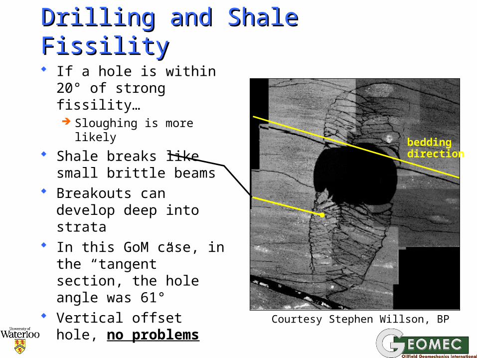
Drilling and Shale FissilityDrilling and Shale Fissility
If a hole is within 20° of strong fissility… Sloughing is more
likely Shale breaks like
small brittle beams Breakouts can
develop deep into strata
In this GoM case, in the “tangent” section, the hole angle was 61°
Vertical offset hole, no problems
beddingdirection
Courtesy Stephen Willson, BP

Coping with Fissile Shale Coping with Fissile Shale SloughingSloughing If possible, stay at least 30° away from the
fissility dip direction (see sketch) Otherwise, keep your mud properties
excellent, keep circulation rate & ECD low, gilsonite and fn-gr LCM in mud may help…
Normal to bedding planes
100-120° coneKeep the drillhole within this cone to avoid severe fissility
sloughing problems

GRDENSITYCURVES
PHOTOELECTRICFACTOR CURVES
BOTTOM OFBOREHOLE
SECTION OFSHALE
BREAKOUTNote that the
majority of theshale sloughingappears to be
from the top of the borehole.
DENSITY NEUTRON IMAGE OF12500’ MD SHALE BREAK OUT
Density Neutron ImageDensity Neutron Image
From: Bruce Matsutsuyu

Drilling Through FaultsDrilling Through Faults
The fault plane region is often:Broken, sheared, weak shales and rocks It may have a high permeability It can be charged with somewhat higher po
First, expect the faults from your data:Seismic data analysisNear salt diapirs, especially shoulders
Accurate mud V(t) measurements can be of great value to good drilling
Cavings monitoring MWD (ECD, resistivity, bit torque…)

Borehole Shear DisplacementBorehole Shear Displacement
High angle faults, fractures can slip and cause pipe pinchingNear-slip earth stresses conditionHigh MW causes pw charging
Reduction in n leads to slipBHA gets stuck on trip out
Can be identified from borehole wall sonic scanner logs (profile logs)
Raising MW makes it worse! Lowering MW is better…
Also, LCM materials to plug the fault or joint plane are effective
npw

Slip of a High-Angle Fault PlaneSlip of a High-Angle Fault Plane
high pressuretransmission
slip of joint
slip of joint surface
borehole
casing bendingand pinching in
completed holes
(after Maury, 1994)
v = 1
h = 3
pipe stuck on trips

Slip Affected by Hole Slip Affected by Hole Orientation!Orientation!
OFFSET ALONG PRE-EXISTING DISCONTINUITIESOFFSET ALONG PRE-EXISTING DISCONTINUITIESFILTRATE
40
45
50
55
60
65
70
75
0 10 20 30 40 50 60 70 80 90 100
Inclination () (deg)
Eff
ec
tiv
e n
orm
al
str
es
s (
ba
r)
0
10
20
30
40
50
60
70
80
90
Azimuth:
TYPICALMUD
OVER-PRESSURE
TYPICALMUD
OVER-PRESSURE Courtesy Geomec a.s.

Diagnostics for Fault Slip Diagnostics for Fault Slip Problems Problems In tectonic areas, near salt diapirs… On trips, BHA gets stuck at one point Easy to drop pipe, hard to raise it Borehole scanner shows strange
shapes: not the same as keyseating or breakouts
Start of keyseat Serious keyseat Evidence of fault plane slip
drill pipe

Curing Fault Plane Slip ProblemsCuring Fault Plane Slip Problems Usually occurs up-hole in normal faulting
regimes that are highly faulted, jointed, as MW is increased to control po downhole
May occur suddenly near the bit when a fault is encountered
Back-ream through the tight zone High pw contributes to the slip of the
plane, thus reduce your MW if possible Condition the mud to block or retard the
flow of mud pressure into the slip plane:Gilsonite, designed LCM in the mud
Use an avoidance trajectory for the well

Mud Volume MeasurementsMud Volume Measurements
Extremely useful, but, accurate V/t needed
Case A: fracture/fault encountered, quickly blocked, now analyze data for k and aperture!
Case B: fractured rock not healed by LCM
Other cases have their own typical response curves (ballooning, slow kick…)
Diagnostics!
20
15
10
5
0
5 6 7 8 9
Losses - gpm
Time - minHole deepening rateFiltration
fluid loss
20
15
10
5
0
5 6 7 8 9
Losses - gpm
Time - minHole deepening rateFiltration
fluid loss
A
B

A Precise Mud Volume A Precise Mud Volume InstallationInstallation
(taken from SPE 38177 - Agip well)
Outlet mud line Precision flow meter

Actual Field Example of AnalysisActual Field Example of Analysis
2890
2910
2930
2950
2970
2990
3010
3030
3050
0 0.5 1
Hydraulic Aperture (mm)
De
pth
(m
)
2890
2910
2930
2950
2970
2990
3010
3030
3050
0 20 40 60
Average permeability (D/m)
This information proved extremely valuable for reservoir engineers in this case, as a gas reservoir was found
Courtesy Geomec a.s

Losses Identify Fractured ZonesLosses Identify Fractured Zones
-20
-10
0
10
20
30
40
50
60
70
4101.5 4101.7 4101.9 4102.1 4102.3 4102.5 4102.7Depth (m)
Qlo
ss (
L/m
in)
22 liters
19 liters
35 liters
25 liters
Mu
d L
os
s R
ate
– li
tre
s/m
in
Depth - m
Likely, each event involved filling a single fracture

Problems in Coal DrillingProblems in Coal Drilling
OBM are worse than WBM in CoalFiltrate penetrates easily (oil wettability)
Coal fractures open easily if pw > po
Coal is extremely compressible Difficult to build a filter cake on the wall
Fissure apertures open with surges Sloughing on trips, connections, large
washouts, … Packing off of cuttings and sloughed
Coal around the pipe, even during trips

Drilling in CoalDrilling in Coal
r
stresses around wellbore
fracture-dominated coal
Deep pore pressure penetration because of coal fractures
Massive sloughing
Mud rings and pack-off caused by slugs of cavings and cuttings

Drilling Fractured Coal SafelyDrilling Fractured Coal Safely
Keep jetting velocities low while drilling through the coal (avoid washouts)
Keep MW modest to avoid fractures opening and coal pressuring, low ECDs while the BHA is opposite the coal seams
Drill with graded LCM in the mud to plug the fractures and build a cake zone
Avoid swabbing and surging on trips See Appendix to Module H for some results
on drilling overbalanced with LCM

A Case History of Salt Diapir A Case History of Salt Diapir Drilling in the North SeaDrilling in the North Sea

North Sea Case, Shallow DepthNorth Sea Case, Shallow DepthWell A
Shallow Gas
Gas Pull Down
1a20
00 m
Courtesy Geomec a.s.

Above a Deep Diapir, North SeaAbove a Deep Diapir, North Sea
Normal faulting observed well above the top of the diapir, these will likely be zones of substantial mud losses (low hmin)
Beds are distorted, likely shearing has occurred along the bedding planes (weaker)
Seismic data show strong “gas pull-down effect”, lower seismic velocities because of free gas in the overlying shales and high po
Free gas zones are noted in the strata, and these will increase gas cuts
(Gas “pull-down” refers to the effect of free gas on seismic stratigraphy)

Deeper, Around the DiapirDeeper, Around the Diapir
Gas Pull Down
Top BalderTop Chalk
Intra Hod/Salt
Well A1b
Mid-Miocene regional pressure boundary
2000 m
3000 m
Courtesy Geomec a.s.
This region avoided

MWD RESISTIVITY LOG SIGNATURE (OBM)MWD RESISTIVITY LOG SIGNATURE (OBM)
Well A
0.1
1
10
100
2540 2560 2580 2600 2620 2640 2660
Depth (m MD-RKB)
MW
D R
esis
tivi
ty (
Oh
m.m
)
SESP
SEDP
Well A
0.1
1
10
100
2540 2560 2580 2600 2620 2640 2660
Depth (m MD-RKB)
MW
D R
esis
tivi
ty (
Oh
m.m
)
SESP
SEDPInvaded ZoneInvaded Zone
Time-lapse and different spacing resistivity logging data identified fractured zone clearly
Courtesy Geomec a.s.

INVADED ZONE Symmetry(O-B)INVADED ZONE Symmetry(O-B)
Well A
0
0.2
0.4
0.6
0.8
1
1.2
1.4
1.6
2540 2560 2580 2600 2620 2640 2660
Depth (m MD-RKB)
Rat
io S
ED
P/S
ES
P (
Oh
m.m
)
Well A
0
0.2
0.4
0.6
0.8
1
1.2
1.4
1.6
2540 2560 2580 2600 2620 2640 2660
Depth (m MD-RKB)
Rat
io S
ED
P/S
ES
P (
Oh
m.m
)
Courtesy Geomec a.s.

What Was Done to Improve What Was Done to Improve Drlg?Drlg? A trajectory was chosen to avoid the worst
of the crestal faulting and gas pressuresShales also intersected at ~ 90to fissility
Mud losses were carefully monitored with depth in the critical zones, then analyzed
Designed LCM in the mud allowed a bit of overbalance in a critical region
Of course, gas cuts, shale chip geometry, total cutting volumes, etc., and many other things were monitored in “real-time”
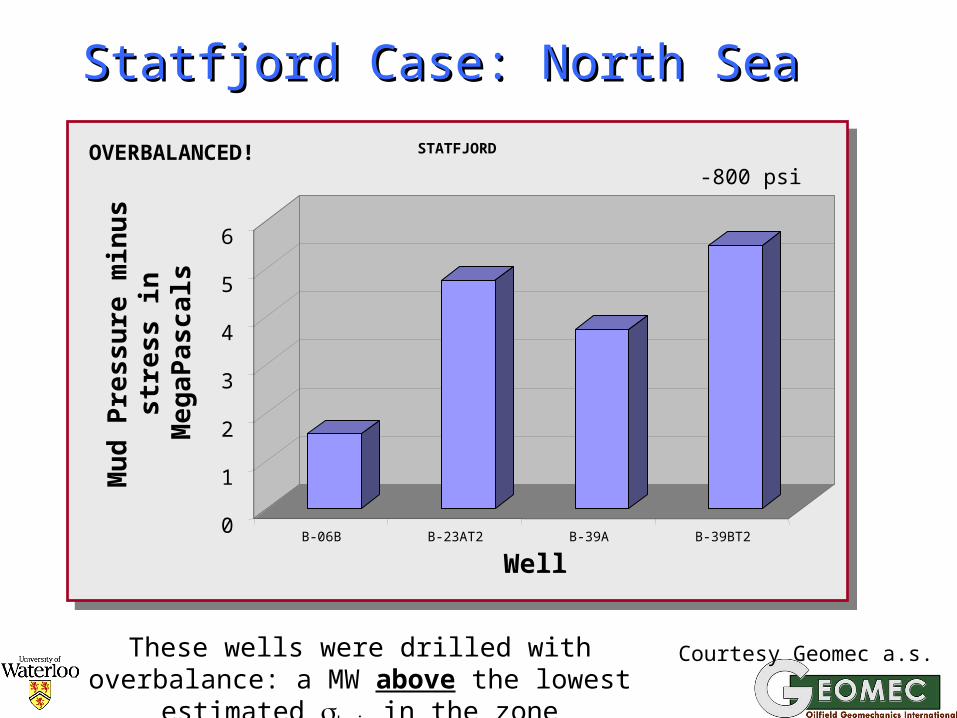
Statfjord Case: North SeaStatfjord Case: North Sea
0
1
2
3
4
5
6
Mu
d P
ress
ure
min
us
s
tre
ss in
Me
ga
Pas
cal
s
B-06B B-23AT2 B-39A B-39BT2
Well
STATFJORD
These wells were drilled with overbalance: a MW above the lowest estimated hmin in the zone
Courtesy Geomec a.s.
OVERBALANCED!-800 psi

Fracturing pressure can be increased by several 100 psi by graded LCM, analysis
Young’s modulus (E) is the control parameter
Induced fractures or even natural fractures encountered open up almost immediately to their final width:This aperture controls LCM design
The plugging happens rapidly with right LCM The effect is enhanced with high viscosity
mud and slower ROP Design tools are available for this
ConclusionsConclusions
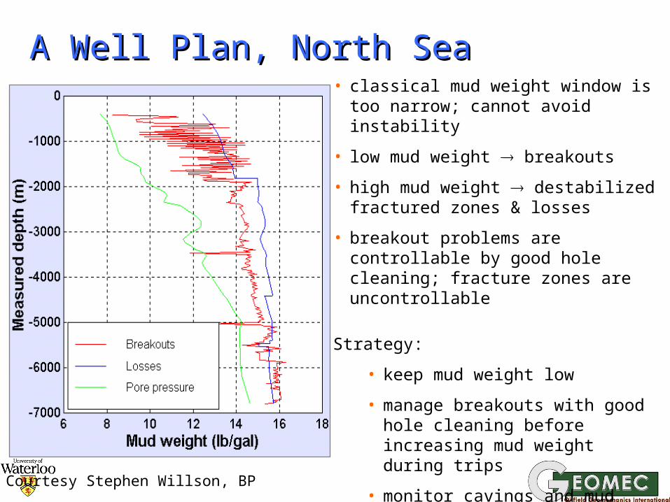
A Well Plan, North SeaA Well Plan, North Sea• classical mud weight window is too
narrow; cannot avoid instability
• low mud weight breakouts
• high mud weight destabilized fractured zones & losses
• breakout problems are controllable by good hole cleaning; fracture zones are uncontrollable
Strategy:
• keep mud weight low
• manage breakouts with good hole cleaning before increasing mud weight during trips
• monitor cavings and mud losses for warning of fractured zones
Courtesy Stephen Willson, BP
Executing this Difficult WellExecuting this Difficult Well
Background gas controlled by ROP, not MW Monitoring greatly reduced “wiper trips” Continuous ECD and mud volume
monitoring to avoid destabilization (+”charged” faults)
Chip analysis to identify fractured shales Strength profile modified “on-the-fly” using
ISONIC MWD + behavior + prognosis Ballooning analysis refined hmin data Hole condition from CRD scan on trips Weighted pills placed for trips Mud properties well maintained (ECD…)

Trajectory Variations ExampleTrajectory Variations Example
Erskine HPHT field Deviated holes need
MWD, better control, the dashed line path was abandoned
Instead, reach was established above HTHP zone, then the well turned vertical
No MWD used, hole cleaning was better, lower ECD, etc…
Also, low flow rates, low surge-swab, etc…
S-profile trajectory
A vertical trajectory in the HTHP zone proved to be cheaper and faster, rather than steering an inclined well trajectory
Reach section
5000 m
Top of HTHP zone
Real-Time Wellbore StabilityReal-Time Wellbore Stability
For deep, difficult, costly holes only Quality prognosis is needed – po(z), hmin(z) Diagnostic tools used:
Real-time pressures (ECD management)Caliper and resistivity data, D-exponent dataBorehole imagery (on trips)Accurate mud loss gauges & ballooning
analysisCuttings volumes and visual classification
Prevention and and remediation options:Mud properties and special chemicalsHydraulics, drilling parameters, reamers…Special cures… (pills, LCM,,,)

Tests on the Rig Floor on ChipsTests on the Rig Floor on Chips
Performed on “intact” cuttings Brinnell hardness is related to strength The dielectric properties can be related
to the shale geochemical sensitivity Sonic travel time can be related to
strength and stiffness empirically You can use dispersion tests in water of
different salinities to assess swelling Even some others can be used These can be taken regularly and plotted
as a log versus depth (very useful)

Mud Cooling to Increase Mud Cooling to Increase Borehole Stability in ShalesBorehole Stability in Shales

Heating and Cooling in the HoleHeating and Cooling in the Hole
depth
T
casing
geothermaltemperature
bit
cooling
heating
mudtemperature
shoe
+T
-T
muddownpipe
mud upannulus
coolingin tanks
BHA
drillpipe
openhole
Heating occurs uphole, cooling downhole. The heating effect can be large, exceptionally 30-35°C in long open-hole sections in areas with high T gradients.
Heating is most serious at the last shoe. The shale expands, and this increases , often promoting failure and sloughing.
At the bit, cooling, shrinkage, both of which enhance stability.
Commercial software exists to draw these curves

T Effects in the BoreholeT Effects in the Borehole
Mud goes down the drillpipe fast: ~5 to 10 faster than it returns up the annulus
It picks up heat from rising mud in annulus At the bit, still 10°-40°C cooler than rock in
HT wells with long open-hole sections Rising uphole, the mud picks up heat from
formation, and heats rapidly till the cross-over point (T diff. Is as large as 30°-40°C)
Then, it cools all the way to the surface It gets to the tanks hot, and loses some
heat, but usually goes back in quite warm

A Simple Quantitative Example…A Simple Quantitative Example…
Change in at the wall is given by: ]ri ~ (T··E)/(1-)
E = Young’s modulus = 1 to 5106 psi = Thermal expan. coef. = 10-1510-6/°C = Poisson’s ratio = 0.30 – 0.35 T = Temperature change Reasonable values are: E = 3106 psi, =
12 10-6/°C, = 0.35, T = +25°C This increases at the wall by ~1400 psi! Not good for shale stability!

Heat Also Reduces Strength a Heat Also Reduces Strength a BitBit
0
20
40
60
80
0 0.5 1 1.5 2 2.5 3 3.5
Strain (%)
Dev
iato
ric
stre
ss (
MP
a) Temperature = 20°C
Temperature = 60°C3 = 2.5 MPa
Mancos shale
About 10% strength loss for this T, so this is a secondary effect

More Temperature EffectsMore Temperature Effects
+T reduces strength, increases stress +T also makes adsorbed water more mobile Absorbed water layer thickness is reduced Either water is expelled, or stresses must
change because the pore pressure changes In either case, additional V takes place, in
addition to thermoelastic effects Furthermore, reaction rates change w. T Boy! Does this make modeling difficult!

Cooling the Mud Reduces +Cooling the Mud Reduces +TT
depth
T
cooling
+T
-T
mud upannulus
BHA
Cooling mud
The mud is cooled at surface through heat exchangers and sea water. As much as -30°C to -40°C is feasible in some cases.
Now, the amount of heating at the shoe is very small, only a few degrees.
Also, the shale remains stronger by virtue of the cooling.
There are other benefits as well…

Benefits of Mud CoolingBenefits of Mud Cooling
Increases shale stability throughout hole! Low temperature reduces the rate of
negative geochemical reactions between the mud filtrate and the shale
Generally, mud properties are far easier to maintain with cooler mud, lower cost
Tanks are less hot (in some areas, mud can exit the hole almost boiling!)
BHA is “protected” from high T Use it when appropriate!

Lessons LearnedLessons Learned
Stability in drilling involves many factorsRock mechanics information, cavings and
cuttings information, rig site tests…Hydraulics managementLithostratigraphic knowledgeMWD in difficult offshore cases (ECD)Temperature managementMW and rheology management
The key is rock mechanics behavior, as stability is mainly a stress issue
But… All factors must be considered together in difficult wells