Embed Size (px)
Citation preview

Manual TABLE OF CONTENTS Module 7. TABLE OF CONTENTS
7-1
MODULE 7. INFORMATION DISSEMINATION
TABLE OF CONTENTS
7.1 INTRODUCTION . . . . . . . . . . . . . . . . . . . . . . . . . . . . . . . . . . . . . . . . . . . . 7-3MODULE OBJECTIVES . . . . . . . . . . . . . . . . . . . . . . . . . . . . . . . . . . . . . . . . . . . . . 7-4MODULE SCOPE . . . . . . . . . . . . . . . . . . . . . . . . . . . . . . . . . . . . . . . . . . . . . . . . . . . 7-4
7.2 DESIGN PROCESS . . . . . . . . . . . . . . . . . . . . . . . . . . . . . . . . . . . . . . . . . . 7-4IDENTIFY NEEDS . . . . . . . . . . . . . . . . . . . . . . . . . . . . . . . . . . . . . . . . . . . . . . . . . . 7-4IDENTIFY INFORMATION DISSEMINATION PARTNERS . . . . . . . . . . . . . . . . . 7-6BUILD CONSENSUS AMONG PARTNERS . . . . . . . . . . . . . . . . . . . . . . . . . . . . . . 7-6
Identify Differences in Operating Philosophies Among Partners . . . . . . . . . . . . . . 7-6Establish Common Ground Between Partners . . . . . . . . . . . . . . . . . . . . . . . . . . . . 7-7
ESTABLISH GOALS AND OBJECTIVES . . . . . . . . . . . . . . . . . . . . . . . . . . . . . . . . 7-7ESTABLISH PERFORMANCE CRITERIA AND MEASURES . . . . . . . . . . . . . . . . 7-8
Information Credibility . . . . . . . . . . . . . . . . . . . . . . . . . . . . . . . . . . . . . . . . . . . . . 7-8Market Penetration . . . . . . . . . . . . . . . . . . . . . . . . . . . . . . . . . . . . . . . . . . . . . . . . 7-8Traveler Response . . . . . . . . . . . . . . . . . . . . . . . . . . . . . . . . . . . . . . . . . . . . . . . . 7-9
FUNCTIONAL REQUIREMENTS . . . . . . . . . . . . . . . . . . . . . . . . . . . . . . . . . . . . . 7-10DEFINE FUNCTIONAL RELATIONSHIPS, DATA REQUIREMENTS, AND
INFORMATION FLOWS . . . . . . . . . . . . . . . . . . . . . . . . . . . . . . . . . . . . . . . . . 7-11IDENTIFY AND SCREEN TECHNOLOGIES . . . . . . . . . . . . . . . . . . . . . . . . . . . . 7-11DEVELOP IMPLEMENTATION PLAN . . . . . . . . . . . . . . . . . . . . . . . . . . . . . . . . 7-12IDENTIFY FUNDING SOURCES . . . . . . . . . . . . . . . . . . . . . . . . . . . . . . . . . . . . . 7-13IMPLEMENT . . . . . . . . . . . . . . . . . . . . . . . . . . . . . . . . . . . . . . . . . . . . . . . . . . . . . 7-14EVALUATE . . . . . . . . . . . . . . . . . . . . . . . . . . . . . . . . . . . . . . . . . . . . . . . . . . . . . . 7-14
7.3 TECHNIQUES AND TECHNOLOGIES . . . . . . . . . . . . . . . . . . . 7-15ON-ROADWAY INFORMATION TECHNOLOGIES . . . . . . . . . . . . . . . . . . . . . . 7-15
Types of DMS . . . . . . . . . . . . . . . . . . . . . . . . . . . . . . . . . . . . . . . . . . . . . . . . . . 7-16Light-Reflecting DMSs . . . . . . . . . . . . . . . . . . . . . . . . . . . . . . . . . . . . . . . . . 7-17
Fold-out. . . . . . . . . . . . . . . . . . . . . . . . . . . . . . . . . . . . . . . . . . . . . . . . . 7-18Scroll (or Tape). . . . . . . . . . . . . . . . . . . . . . . . . . . . . . . . . . . . . . . . . . . . 7-18Rotating Drum. . . . . . . . . . . . . . . . . . . . . . . . . . . . . . . . . . . . . . . . . . . . . 7-19Reflective Disk Matrix. . . . . . . . . . . . . . . . . . . . . . . . . . . . . . . . . . . . . . . 7-19
Light-Emitting DMSs . . . . . . . . . . . . . . . . . . . . . . . . . . . . . . . . . . . . . . . . . . 7-19Neon or Blank-Out Signs. . . . . . . . . . . . . . . . . . . . . . . . . . . . . . . . . . . . . 7-19Lamp (Incandescent Bulb) Matrix Signs. . . . . . . . . . . . . . . . . . . . . . . . . . 7-19Fixed-Grid or Shuttered Matrix Fiber-optic Signs. . . . . . . . . . . . . . . . . . 7-19Fixed-Grid or Matrix Light-Emitting Diode (LED) Signs. . . . . . . . . . . . . 7-20
Hybrid DMSs . . . . . . . . . . . . . . . . . . . . . . . . . . . . . . . . . . . . . . . . . . . . . . . . 7-20Reflective Disks with Fiberoptics/LEDs. . . . . . . . . . . . . . . . . . . . . . . . . . 7-20Static/DMS. . . . . . . . . . . . . . . . . . . . . . . . . . . . . . . . . . . . . . . . . . . . . . . 7-20
Advantages and Disadvantages of the DMS Technologies . . . . . . . . . . . . . . . . . 7-20

Manual TABLE OF CONTENTS Module 7. TABLE OF CONTENTS
7-2
IN-VEHICLE INFORMATION . . . . . . . . . . . . . . . . . . . . . . . . . . . . . . . . . . . . . . . 7-21Auditory In-Vehicle Information Technologies . . . . . . . . . . . . . . . . . . . . . . . . . . 7-21
Highway Advisory Radio . . . . . . . . . . . . . . . . . . . . . . . . . . . . . . . . . . . . . . . 7-21Automated HAR (AHAR) . . . . . . . . . . . . . . . . . . . . . . . . . . . . . . . . . . . . . . . 7-24Cellular Telephone “Hotlines” . . . . . . . . . . . . . . . . . . . . . . . . . . . . . . . . . . 7-25Commercial Radio . . . . . . . . . . . . . . . . . . . . . . . . . . . . . . . . . . . . . . . . . . . . 7-26Citizen-Band Radio . . . . . . . . . . . . . . . . . . . . . . . . . . . . . . . . . . . . . . . . . . . 7-26
Visual In-vehicle Information Technologies . . . . . . . . . . . . . . . . . . . . . . . . . . . . 7-26Video Display Terminals . . . . . . . . . . . . . . . . . . . . . . . . . . . . . . . . . . . . . . . 7-26Head-Up Displays . . . . . . . . . . . . . . . . . . . . . . . . . . . . . . . . . . . . . . . . . . . . 7-27
OFF-ROADWAY INFORMATION . . . . . . . . . . . . . . . . . . . . . . . . . . . . . . . . . . . . 7-27Television . . . . . . . . . . . . . . . . . . . . . . . . . . . . . . . . . . . . . . . . . . . . . . . . . . . . . 7-28Telephones . . . . . . . . . . . . . . . . . . . . . . . . . . . . . . . . . . . . . . . . . . . . . . . . . . . . . 7-28Pagers . . . . . . . . . . . . . . . . . . . . . . . . . . . . . . . . . . . . . . . . . . . . . . . . . . . . . . . . 7-28Personal Data Assistants (PDAs) . . . . . . . . . . . . . . . . . . . . . . . . . . . . . . . . . . . . 7-29Computers (Internet) . . . . . . . . . . . . . . . . . . . . . . . . . . . . . . . . . . . . . . . . . . . . . 7-29Kiosks . . . . . . . . . . . . . . . . . . . . . . . . . . . . . . . . . . . . . . . . . . . . . . . . . . . . . . . . 7-29
7.4 LESSONS LEARNED . . . . . . . . . . . . . . . . . . . . . . . . . . . . . . . . . . . . . . . 7-30NTCIP STANDARDS . . . . . . . . . . . . . . . . . . . . . . . . . . . . . . . . . . . . . . . . . . . . . . . 7-30INFORMATION MESSAGE DESIGN . . . . . . . . . . . . . . . . . . . . . . . . . . . . . . . . . . 7-30ENVIRONMENTAL ISSUES CONCERNING DMSs . . . . . . . . . . . . . . . . . . . . . . 7-31
Sun Position . . . . . . . . . . . . . . . . . . . . . . . . . . . . . . . . . . . . . . . . . . . . . . . . . . . . 7-31Weathering . . . . . . . . . . . . . . . . . . . . . . . . . . . . . . . . . . . . . . . . . . . . . . . . . . . . 7-31
“AT-REST” DISPLAY CONDITIONS . . . . . . . . . . . . . . . . . . . . . . . . . . . . . . . . . . 7-31
7.5 EXAMPLE OF AN INFORMATION DISSEMINATIONSYSTEM: TRANSCOM . . . . . . . . . . . . . . . . . . . . . . . . . . . . . . . . . . . . . 7-31ORGANIZATION . . . . . . . . . . . . . . . . . . . . . . . . . . . . . . . . . . . . . . . . . . . . . . . . . . 7-31OPERATIONS . . . . . . . . . . . . . . . . . . . . . . . . . . . . . . . . . . . . . . . . . . . . . . . . . . . . 7-32FUTURE ACTIVITIES . . . . . . . . . . . . . . . . . . . . . . . . . . . . . . . . . . . . . . . . . . . . . . 7-33
7.6 REFERENCES . . . . . . . . . . . . . . . . . . . . . . . . . . . . . . . . . . . . . . . . . . . . . . 7-35

Manual TABLE OF CONTENTS Module 7. TABLE OF CONTENTS
7-3
Figure 7-1. Dynamic Message Signing on New Jersey Turnpike.
MODULE 7. INFORMATION DISSEMINATION
7.1 INTRODUCTION
It is well known that the key to successfuldriving task performance is efficientinformation gathering and processing.(1)
Likewise, properly communicating withmotorists is critical to successful freewaytraffic management and operations.Motorists rely on a wide variety ofinformation to properly accomplish thecontrol, guidance, and navigational aspectsof the driving task. The roadway alignmentand general terrain itself provides a greatdeal of this information through visual“cues;” sources such as pavement markingsand regulatory, warning, and guide signsalso contribute greatly to the overall
information system. However, in aneffective freeway management system,dynamic methods of conveying informationto motorists or travelers are often needed tobetter operate and control the system.
Freeway management systems rely onvarious information disseminationcomponents to apprise all types of travelers(motorists, transit users, commercial vehicleoperators, etc.) of current and anticipatedtravel conditions so that informed mode,departure time, and route choice decisionscan be made.
Information dissemination is also managed inorder to improve travel conditions in the
Manual TABLE OF CONTENTS Module 7. TABLE OF CONTENTS
7-4
corridor by influencing traveler behavior (by and technologies being utilized forrecommending diversion routes around an information dissemination within theincident, for example). This information can integrated regional transportationbe disseminated from a variety of sources management system.(State departments of transportation, transitagencies, private-sector information serviceproviders, etc.) using a variety of methods(dynamic message signs, commercial radiotraffic reports, traffic information kiosks,etc.).
MODULE OBJECTIVES
The objectives of this module are threefold:
C To describe how to define, establish, andcoordinate effective traveler informationcomponents in a freeway managementsystem.
C To identify existing and emergingtechnologies available to facilitateinformation dissemination to travelers.
C To illustrate how informationdissemination components can integratewith each other and with othercomponents of a freeway managementsystem.
MODULE SCOPE
This module addresses both traditional andemerging information disseminationprocesses and technologies for freewaymanagement systems. Whereas a number oftechnologies (i.e., dynamic message signs,highway advisory radio) have been aroundfor a number of years, there are newopportunities today. In the past, informationwas distributed in response to an incident.Today, the focus is to provide a continuousflow of information to travelers, businesses,and commercial carriers in order to maketheir trip travel time more predictable. Thefocus of this module is to emphasize theneed for integration among all components
7.2 DESIGN PROCESS
Decisions about when, where, and how todisseminate travel-related information to thepublic have become much more complex inrecent years, due to improved traffic/weather/transit surveillance capabilities andexpanded information dissemination options.As with the other components that can beincluded in a freeway management system,the decisions necessary to develop andintegrate information dissemination into thesystem can be best accomplished byfollowing the basic decision processdescribed in Module 2. Specific applicationof this process to the task of incorporatinginformation dissemination into a freewaymanagement system is discussed in thefollowing sections.
IDENTIFY NEEDS
The first step in the decision process is toidentify the need to be addressed throughinformation dissemination, or stated anotherway, the information needs that exist in thefreeway corridor. Two basic categories ofinformation dissemination exist:
C Pre-trip planning.
C En route guidance and information.
Table 7-1 presents examples of some of thespecific types of need and/or informationneeds in these categories. Certaininformation may be needed both pre-trip anden route, whereas other information may beneeded for either one or the other. To theextent possible, these information needsshould be further defined by the following:

Manual TABLE OF CONTENTS Module 7. TABLE OF CONTENTS
7-5
Table 7-1. Information Need Categories.
Category Examples of Information Need
pre-trip planning C current/anticipated traffic conditions - speeds- incident locations- other congestion locations- upcoming road closures
C weather effects- pavement conditions- road closures
C route guidance- around incidents- to special events
C transit information- bus schedules and status- transfer locations- rideshare matching (preplanning and real-time matching)
en route guidance and C current traffic conditions information - speeds
- incident locations- other congestion locations
C weather effects- pavement conditions- road closures
C route guidance- around incidents- to special events
C lane/shoulder/ramp use status
C Audience. is also important early on to identify those
C Location. of agencies and/or the private sector to
C Time-of-day. concerns can be one such factor. Some
These characteristics affect how well pavement condition information, forinformation can be received by the users, and example, for fear of establishing a precedentwhat types of responses can be expected that may be used against them if they fail tofrom the users who have that information warn of that pavement condition (or aavailable. similar one) in the future. Preestablished
In addition to the needs to be addressed private sector companies regarding access tothrough information dissemination efforts, it
factors or issues that will influence the ability
provide that information. Tort liability
agencies may avoid providing current
agreements between public agencies and
Manual TABLE OF CONTENTS Module 7. TABLE OF CONTENTS
7-6
agency data may also influence the directionof future dissemination efforts.
The problem identification step of thedecision process also includes an inventoryof existing information sources, includingmedia reports and private sector initiatives. Developing a consensus regarding theThe inventory can include such data items as importance of information dissemination andtarget audiences, accessibility, frequency of its role as part of an overall freewayreports, and information accuracy. If management system is the next step in thepossible, assessments of user satisfaction decision process. It is important that projectwith the information should also be obtained. partners take ownership of the effort up
IDENTIFY INFORMATIONDISSEMINATION PARTNERS
The key partners in the development of the involved. information dissemination component of afreeway management system include the For example, highway and transit agenciesfollowing: may view the presence of some degree of
C Traditional State and local public sector different ways if an HOV lane is includedagencies (transportation and public within the freeway right-of-way. Whereasworks, transit, toll authorities, law diverting freeway traffic to arterial streetsenforcement). might be a primary goal of the highway
C Commercial media. promote bus utilization and the HOV lane as
C Private sector traffic reporting services Partners need to communicate these(distributing through commercial media concerns to each other so that a consensusvenues or through direct subscription to about goals can be reached.motorists).
C Local fleet operators (delivery services, differences in operational philosophiestaxis, etc.). between public agencies and private sector
In some cases, the owners/operators of drive public agency decisions regarding themajor traffic generators (malls, tourist dissemination of travel-related information,attractions, annual special event promotions, marketing opportunities and profit motivesetc.) could also be important partners to will generally dictate private sector interests,include in the decision-making process. perceptions, and decisions. A clear under-
BUILD CONSENSUS AMONGPARTNERS
Identify Differences in OperatingPhilosophies Among Partners
front, or it may never work. To make thishappen, it is important to identify andunderstand the differences in operationalphilosophies of the different partners
recurrent congestion on the freeway in very
agency, the transit agency may desire to
a means of reducing that congestion.
The partners must also be aware of the
entities. Whereas equity concerns typically
standing of the differences among thesephilosophies is required.

Manual TABLE OF CONTENTS Module 7. TABLE OF CONTENTS
7-7
Establish Common Ground Between ESTABLISH GOALS ANDPartners OBJECTIVES
Once operational and philosophical differ- Once a consensus has been establishedences among the various partners have been among the partners involved withidentified, the next step is to establish areas information dissemination efforts, it isof common concern or priorities between the necessary to define the goals and specificpartners with respect to travel-related objectives that are going to be addressedinformation dissemination. Common ground through this component of the freewaymust be established both at the upper management system. As discussed inmanagement and political level, and at the Module 2, goals are broad statements of theday-to-day operations level. Information intent of the system or one of itsdissemination requires upper management components, whereas objectives are specificand political support of a common vision of statements about what the system orinformation availability in order to ensure component of that system will attempt tocontinued funding support. Meanwhile, accomplish. A given goal may have moreconsensus among partners at the operations than one objective specified to reach thatlevel is needed to promote true operations goal. Table 7-2 presents examples of goalsintegration among the various information and objectives an agency might have for thedissemination components utilized within the information dissemination component of itscorridor. freeway management system.
Table 7-2. Examples of Goals and Objectives for Information Dissemination.
Category Examples
Goals C Reduce motorist demands upstream of a freewayincident
C Reduce motorist errors in locating unfamiliardestinations
C Reduce transit user uncertainty about bus arrivals
Objectives C Warn motorists of adverse weather conditionsC Notify motorists of downstream incidentsC Advise motorists when to seek alternative routesC Provide motorists with origin-to-destination route
guidance assistanceC Inform motorists at park-and-ride lots when the next
bus will arrive

Manual TABLE OF CONTENTS Module 7. TABLE OF CONTENTS
7-8
In general terms, each of the objectives C The information must be accurate.developed for information disseminationshould be specific enough to answer the C The information must be timely.following questions: (1)
C Who is being communicated with? intended audience.
C What responses are desired or While these are generally accepted concepts,anticipated? it is sometimes difficult to identify and obtain
C Where will the responses take place? which to judge them. This task is further
ESTABLISH PERFORMANCECRITERIA AND MEASURES
In order to assess the extent to which mance measures that could be used toinformation dissemination efforts within a evaluate the credibility of information beingfreeway management system are meeting disseminated to motorists are provided ingoals and objectives, a set of performance Table 7-3. Local concerns and capabilitiescriteria and measures-of-effectiveness will dictate which performance measures arepertaining to these efforts must be identified. most appropriate for evaluating informationRelative to information dissemination, credibility in a given locale.performance criteria have three differentdimensions that are of interest:
C Information credibility. Market penetration refers to the percentage
C Market penetration. information dissemination efforts.
C Traveler response. penetration may be appropriate for
These three dimensions are interrelated. The technologies, particularly those emerging asfollowing sections provide additional details part of Advanced Traveler Informationand examples of criteria for each of the Systems (ATIS). It is expected that someabove dimensions. technologies, such as in-vehicle dynamic
Information Credibility
An information dissemination tool must be such as information kiosks in major trafficcredible to travelers if it is to be utilized and generators, may require agencies to strivehave an impact upon traffic operations. The for as great a market penetration as possiblefollowing criteria define how credibility is in order to distribute the information to aestablished: wider audience and possibly attract private(2)
C The information must be relevant to its
objective and quantifiable measures with
complicated by the fact that the measuresthemselves may depend on the specificmessage or unit of information that a partneris trying to convey. Examples of perfor-
Market Penetration
of the potential audience reached by the
Performance criteria regarding market
evaluating certain system goals and
route guidance, will require only limitedmarket penetration in order to achieveoperational benefits. Other technologies,
sector advertising and sponsorship.

Manual TABLE OF CONTENTS Module 7. TABLE OF CONTENTS
7-9
Table 7-3. Examples of Performance Measures for Information Dissemination.
Category Examples
Information accuracy C Difference in the number of incidents in the system andnumber of incidents reported
C Difference between reported expected arrival times of busesand the times the buses actually arrive at a transit station
C Number of complaints received from the public aboutinaccurate information (by device and type of information)
Information timeliness C Average delay time between when an incident is verified andwhen information about the incident is disseminated totravelers
Information relevance C Number of travelers who access a given informationcomponent or unit
Traveler Response
Ultimately, the purpose of providing dissemination modes upon traffic volumes,information to travelers is to effect some- speeds, or delays. The day-to-day varianceschange in traveler behavior that will cause an in travel patterns themselves may mask theimprovement in safety or operations. Thus, effects of any information disseminatedperformance measures are also needed to during a specific event such as an incident,determine the extent to which information particularly if the information is intended fordissemination accomplishes this purpose. a very specific audience (such as vehiclesChanges in traveler mode, departure time, within a freeway traffic stream destined forand route (if appropriate) are appropriate for a specific downstream exit). evaluating the effectiveness of real-timetravel-related information. However, it may Consequently, it may sometimes bebe very difficult and expensive to obtain necessary to include performance measuresactual data for these measures. Traveler that evaluate the effect of informationopinions about the effectiveness of the dissemination at an individual traveler’sinformation being provided can be another level. For example, trip diaries that identifyimportant eval-uation measure. Reductions a specific driver’s travels on any given dayin travel time, turning and route choice may need to be compared to determineerrors, or similar measures may also be whether the presence of information had anyuseful to evaluate certain types of influence on driving behavior for that selectinformation. group with drivers on that particular day. (3)
It is important to recognize that because of manpower intensive, however.the complex travel patterns of travelers atany point in the roadway, it may not be
possible to adequately measure the overalleffects of many types of information or
This approach can be very costly and
Manual TABLE OF CONTENTS Module 7. TABLE OF CONTENTS
7-10
FUNCTIONAL REQUIREMENTS
The functional requirements of information requirements definition process fordissemination components in a freeway information dissemination. The functionsmanagement system define specific actions described in the National Architecture mustor activities that are to be performed in order then be detailed to match the needs andto achieve one or more of the objectives. desires of the local agencies. Initially, the functions should be definedwithout considering the dissemination Details regarding who should receivetechnology or system architecture that will information, as well as when and where thatbe employed. Functions simply specify what should occur, all become a part of theinformation will be disseminated and functional definitions. The intent of this steppossibly when and where it is to be in the design process is not only to specifypresented, not how this will be done. Table functions independent of the technology that7-4 presents some examples of functional could be used to achieve those functions, butrequirements for various information also to highlight what and why otherdissemination objectives. components of the freeway management
The ITS National Architecture should serveas the basic building block of the functional
(4)
system must link with the informationdissemination components.
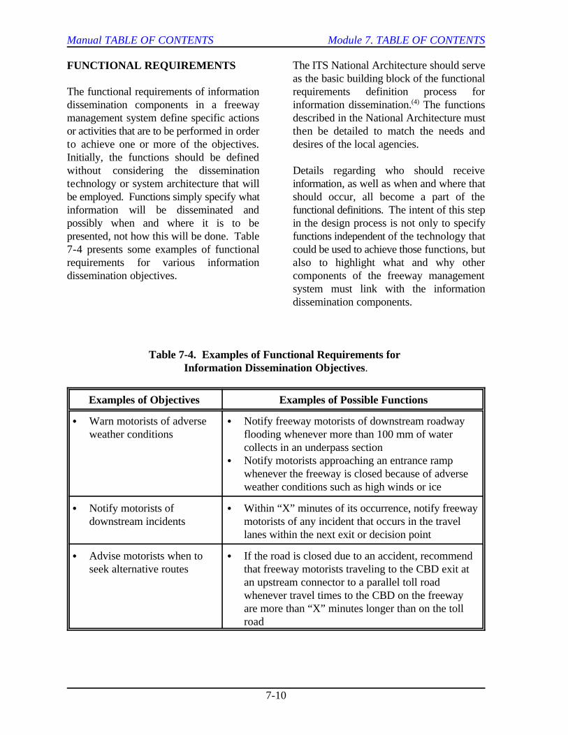
Table 7-4. Examples of Functional Requirements for Information Dissemination Objectives.
Examples of Objectives Examples of Possible Functions
C Warn motorists of adverse C Notify freeway motorists of downstream roadwayweather conditions flooding whenever more than 100 mm of water
collects in an underpass sectionC Notify motorists approaching an entrance ramp
whenever the freeway is closed because of adverseweather conditions such as high winds or ice
C Notify motorists of C Within “X” minutes of its occurrence, notify freewaydownstream incidents motorists of any incident that occurs in the travel
lanes within the next exit or decision point
C Advise motorists when to C If the road is closed due to an accident, recommendseek alternative routes that freeway motorists traveling to the CBD exit at
an upstream connector to a parallel toll roadwhenever travel times to the CBD on the freewayare more than “X” minutes longer than on the tollroad

Manual TABLE OF CONTENTS Module 7. TABLE OF CONTENTS
7-11
For example, an information dissemination Locations of potential informationfunction that gives route specific travel times dissemination conflicts can be identifiedrequires that travel time monitoring be a beforehand (a highway and a transit agencyfunction in the freeway management system. may want to display information at the sameLikewise, a function of notifying motorists roadway location, for example). Perhapsabout downstream lane-blocking incidents more commonly, locations and situationswithin a set time also affects the design of where information sharing between partnersthe freeway surveillance component of the can occur may be identified, and result in afreeway management system (what type of more efficient system design.vehicle detection technology can be used,how close together detectors must beplaced, etc.). As a final example, notifyingmotorists that lanes are closed downstreamfor maintenance work implies that a Once the system requirements formechanism for determining when and where information dissemination have beensuch closures occur is available via direct developed, it is then appropriate to assesscommunication between the maintenance the actual technologies available to meet theand operations divisions of the functional and system architecturaltransportation agency, observation of the requirements that have been developed forclosure via closed-circuit television, or other meeting the goals and objectives ofmethods. information dissemination. Technologies
DEFINE FUNCTIONALRELATIONSHIPS, DATAREQUIREMENTS, ANDINFORMATION FLOWS
The purpose of defining functional occurs at a specific point or within arelationships, data requirements, and very small segment of roadway (i.e.,information flows is to establish an using dynamic message signs or highwayunderstanding of how the various advisory radios.)information dissemination functions that areto be accomplished will be integrated with C Those located within the vehicle whereeach other and with the other components in the information transfer is notthe freeway management system. In this constrained to a point or a small segmentstep, the relationships between information of roadway (e.g., using radio, cellulardissemination functions are further refined to telephone, or in-vehicle navigationincorporate local issues, concerns, and devices).capabilities.
The relationships between the desired roadway altogether (e.g., usinginformation dissemination functions and television, computer linkages, or kiosksnecessary data flows to those functions can in major traffic generators).be particularly important when designing afreeway management system, especially if A review of the technologies in each of theseseveral partners are involved in the three categories is provided later in thisinformation dissemination process. module. This review can serve as the
IDENTIFY AND SCREENTECHNOLOGIES
that are available for informationdissemination can be grouped into one ofthree categories:
C Those located on the roadway where theinformation transfer to the traveler
C Those located off of or away from the
Manual TABLE OF CONTENTS Module 7. TABLE OF CONTENTS
7-12
starting point for the technology screening Implementation plan development isprocess. However, technology in the governed by federal guidelines, and isinformation dissemination realm continues to required for all new or expanded trafficchange rapidly and should be reassessed control system projects that utilize federaleach time this point is reached in the decision funds. Actually, an implementation plan isprocess. a good idea for all traffic control system
Initial screening can be used to determine utilize federal funds. which of the three basic categories can beused to effectively accomplish each of the Module 2 described the general guidelinesspecified information dissemination regarding overall plan development for afunctions. More than one of the categories freeway management system. In thismay be useable. Then, within each category, section, special issues of plan developmenta more detailed screening and evaluation are discussed that relate specifically to theprocess can help select among the various information dissemination components of aalternatives of that technology. Screening freeway management system.should include such considerations as thefollowing: Because information dissemination must be(5)
coordinated among the various partners, aC Legibility (for visual information portion of the plan should be devoted to a
components). discussion of the management structure and
C Reliability. achieve this coordination. Items to be
C Costs to the user and public agency follows: (these should be life-cycle costs,discussed in greater detail in Module C Names of contact person(s) for each11). partner.
C Potential market size. C Protocols and methods to be utilized to
If, for some reason, the screening processdoes not identify technologies that can C Definition of each partner’sadequately perform the functions that were responsibilities regarding informationestablished, then the analyst must step exchange.backwards and reassess the objectives and/orfunctions of the information dissemination C Estimates of each partner’s financialcomponent of the freeway management contribution to the effort (cash, in-kindsystem. Objectives and associated functions exchange of equipment or services, etc.).may have to be scaled back or otherwisemodified. C Letters or memoranda of agreement
DEVELOP IMPLEMENTATIONPLAN
The next step in the process is the the letter of agreement if some of thedevelopment of an implementation plan. partners will jointly operate some of the
(6)
projects, regardless of whether or not they
the agreements that will be utilized to
included in this portion of the plan are as
coordinate.
regarding the desire to coordinate amongpartners.
Additional details may need to be included in
Manual TABLE OF CONTENTS Module 7. TABLE OF CONTENTS
7-13
information dissemination technologies to be information dissemination rules for theimplemented. For example, a transportation system they have learned to decide whatagency may wish to allow law enforcement messages need to be displayed, on whichpersonnel to access and utilize their dynamic signs they should be displayed, etc.message signs or highway advisory radioequipment for managing major incidentsduring late-night hours when thetransportation agency does not have Identification of funding source alternativessomeone on duty. actually occurs as part of the plan
A detailed implementation plan is also components of freeway managementneeded in order to properly coordinate systems, the partners involved in informationinformation dissemination within the freeway dissemination can share costs through somemanagement system. Whereas the letters of combination of the following:agreement and discussion of themanagement structure lay out broad C Individual agency hardware purchasesadministrative boundaries and consensus to and operation/maintenance which iscoordinate, the implementation plan spells coordinated with another agency’sout in detail how this will occur. efforts in the region.
An implementation plan may include specific C In-kind contribution of equipment andpreplanned actions that will be taken in services to a pooled service.response to certain common or expectedsituations (i.e., which dynamic message signs C Establishment of user fee scheduleswill be activated and what will be displayed (direct or indirect).on them in response to an incident thatoccurs on a specific section of freeway), as Several different cooperative institutionalwell as more general rules that will be used arrangements have been successfully utilizedto decide what information to present for to distribute information dissemination costsunusual, unexpected situations. For in a rational and equitable manner to publicexample, the TransGuide Traffic and private partners. For the TRANSCOMManagement System in San Antonio, Texas organization in New York/New Jersey, cashhas over 60,000 preplanned “scenarios” and in-kind contributions from each membercoded into a computerized database. agency fund the operations of theDepending on the time of day, location of an organization. Each partner has an officialincident, and the number of lanes that are assigned to the TRANSCOM executiveblocked, a specific scenario is selected that committee, which works together todefines which dynamic message signs and establish the actual fee structure,lane control signals are to be activated and management policies, and other matters ofthe messages that are to be displayed on concern to the agencies as a group. each (i.e., “LEFT LANE CLOSEDAHEAD”). Most of the time, system In Boston, the SmarTraveler cellular call-inoperators simply activate one of these system is sponsored in large part by FHWApreplanned actions. Occasionally, a freeway and the Massachusetts Highway Depart-problem develops for which preplanned ment, but is managed by a private-sectoractions have not been developed. In these limited partnership, SmartRoute. Severalcases, system operators use basic other private-sector companies (cellular
IDENTIFY FUNDING SOURCES
development process. As with the other
(9)
(10)

Manual TABLE OF CONTENTS Module 7. TABLE OF CONTENTS
7-14
telephone companies, a paging company, the credibility of the overall system with theand broadcast media) purchase some of the traveler can be severely degraded by havinginformation being managed and the devices in place and not using them or bydisseminated, which has helped offset some having the devices display wrongof the costs to the public agencies. information. One of the problems reported (11)
In San Antonio, Texas, both public and York was that the DMSs for the projectprivate-sector partners have entered into a were installed early on in the contract andCooperative Industry Product Agreement to then sat there unused for several years as thefacilitate the development and agencies built the rest of the infrastructure.implementation of the software that will Since it was not immediately apparent todecode the video and data transmissions motorists why the devices could not be usedfrom a low-power television station that the to communicate about downstream roadwayTexas Department of Transportation has and traffic conditions, public opinion aboutpurchased and will operate. This has the project suffered. (12)
allowed the various potential beneficiaries ofthe system (i.e., media stations, fleet Another important facet of informationoperators, etc.) to contribute to software dissemination implementation is thedevelopment for a relatively small price (and development of training necessary to assistrisk). Furthermore, it provides a mechanism travelers in correctly interpreting andto allow future partners to enter into the responding to some of the informationagreement in a fair and equitable manner. dissemination technologies. For example,(12)
IMPLEMENT
Implementation of information dissemination lane periodically throughout the freewaycomponents in the freeway management network. As a result, motorist compre-system occurs as a natural result of following hension of the available symbols for thethe systems engineering process. Module 2 signals are somewhat higher in Fort Worthdescribed, in general terms, the than in other locations in Texas. Otherimplementation activities that should occur possible training alternatives include publicat this point in the process. In addition to service announcements or mailing inserts inthe issues brought out in that module, other local utility bills. concerns that pertain directly to informationdissemination include:
C Implementation schedule. The final step in the design process is to
C User training. dissemination component of the freeway
Information dissemination is the main link uation should not be considered a one-timebetween the freeway management system activity, but should be part of a periodicand the motoring public. Experience review of the effectiveness of theindicates that the implementation of information dissemination components andinformation dissemination devices should of the overall system. As discussedoccur only after the surveillance and control previously, it is rather difficult to measureinfrastructure has been installed. Otherwise, the impact of information dissemination
by officials of the INFORM project in New
the Texas Department of Transportation inFort Worth displays the meaning of lanecontrol signals mounted over each travel
(13)
EVALUATE
evaluate the effectiveness of the information
management system. However, this eval-

Manual TABLE OF CONTENTS Module 7. TABLE OF CONTENTS
7-15
upon overall traffic measures, because of the Specific technologies available in each ofstochastic nature of travel demands and these categories are discussed below.behavior in a given freeway corridor, as wellas the events which cause disruptions tothese demands (incidents, special events,etc.).
One of the most fundamental technologiesCare should be taken not to overestimate the available for disseminating traffic-relatedbenefits achieved by the implementation of information from the roadside is that ofinformation dissemination components in a dynamic message signs (DMS). DMSs arefreeway management system. Specifically, it sometimes referred to as changeableis important to recognize that travel patterns message signs (CMS) or variable messagein a freeway corridor are quite dynamic, and signs (VMS). DMSs allow operatingthat some drivers will divert naturally when agencies to visually disseminate travelthey encounter freeway congestion information to motorists on a near real-timeregardless of whether or not they receive basis. DMSs use words, numbers, orinformation beforehand about that symbols to convey information. They arecongestion. Therefore, information extremely flexible and powerful trafficdissemination should be considered as management tools in freeway operations.having an incremental effect upon trafficconditions by modifying where and how DMSs can be either portable or fixed, andsome travelers respond to congestion (where can be operated either on a fixed-time basistravel routes are changed, how many with on-site control or interconnected withmotorists change departure times, how many a traffic control center to provide remotechanged modes, etc.). control. DMSs can be used to perform the
7.3 TECHNIQUES ANDTECHNOLOGIES
Information dissemination components of afreeway management system can range froma single device owned and operated by oneagency, to an integrated collection of devicesand mechanisms under the control of severalagencies and several private sector entities.In this handbook, a basic distinction is madebetween kinds of information depending onwhich of three main locations it comes from:
C On-roadway information.
C In-vehicle information.
C Off-roadway information (typically atorigin of a trip).
ON-ROADWAY INFORMATIONTECHNOLOGIES
(14)
following functions:
C Inform motorists of varying traffic,roadway, and environmental conditions.
C Provide specific information relative tothe location and delays associated withincidents.
C Advise motorists on detour routesbecause of construction or roadwayclosure.
C Suggest alternate routes to avoidfreeway congestion.
C Reassure drivers on unfamiliar alternateroutes.
C Redirect diverted drivers back tofreeways.
Manual TABLE OF CONTENTS Module 7. TABLE OF CONTENTS
7-16
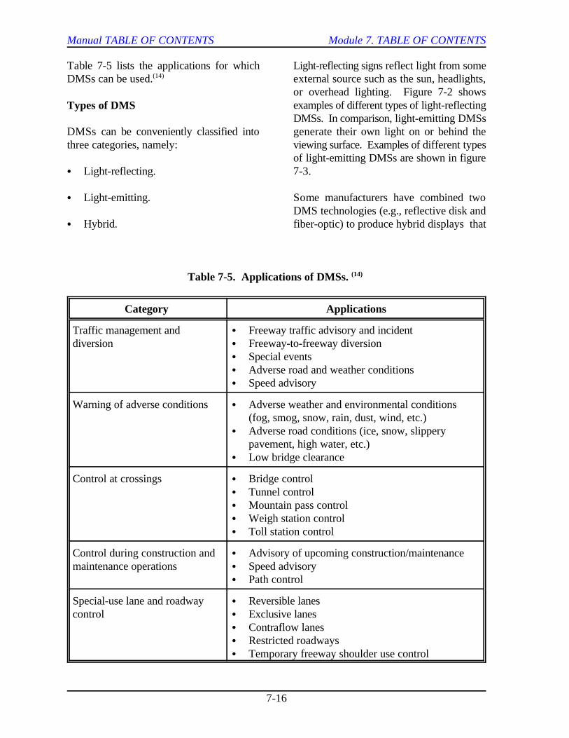
Table 7-5 lists the applications for which Light-reflecting signs reflect light from someDMSs can be used. external source such as the sun, headlights,(14)
Types of DMS
DMSs can be conveniently classified into generate their own light on or behind thethree categories, namely: viewing surface. Examples of different types
C Light-reflecting. 7-3.
C Light-emitting. Some manufacturers have combined two
C Hybrid. fiber-optic) to produce hybrid displays that
or overhead lighting. Figure 7-2 showsexamples of different types of light-reflectingDMSs. In comparison, light-emitting DMSs
of light-emitting DMSs are shown in figure
DMS technologies (e.g., reflective disk and
Table 7-5. Applications of DMSs. (14)
Category Applications
Traffic management and C Freeway traffic advisory and incidentdiversion C Freeway-to-freeway diversion
C Special eventsC Adverse road and weather conditionsC Speed advisory
Warning of adverse conditions C Adverse weather and environmental conditions(fog, smog, snow, rain, dust, wind, etc.)
C Adverse road conditions (ice, snow, slipperypavement, high water, etc.)
C Low bridge clearance
Control at crossings C Bridge controlC Tunnel controlC Mountain pass controlC Weigh station controlC Toll station control
Control during construction and C Advisory of upcoming construction/maintenancemaintenance operations C Speed advisory
C Path control
Special-use lane and roadway C Reversible lanescontrol C Exclusive lanes
C Contraflow lanesC Restricted roadwaysC Temporary freeway shoulder use control

Manual TABLE OF CONTENTS Module 7. TABLE OF CONTENTS
7-17
Figure 7-2. Examples of Light-Reflecting DMS Technologies.
exhibit the qualities of both. Some agencieshave also combined DMSs with staticdisplays to form what can also be considered The basic categories of light-reflectingto be hybrid displays. DMSs are as follows:
Several references are available that describe C Fold-out.the operational and performancecharacteristics of various DMSs (see C Scroll.references 1, 14, 15, 16) The followingparagraphs, taken from those references, C Rotating drum.briefly describe the different types of DMSsin each category. C Reflective disk matrix.
Light-Reflecting DMSs
Basic operations and characteristics of eachare described below.

Manual TABLE OF CONTENTS Module 7. TABLE OF CONTENTS
7-18
Figure 7-3. Examples of Light-Emitting DMS Technologies.
Fold-out. A fold-out sign is a conventionalhighway sign with a hinged viewing face.This type of sign can either display twomessages (one with the hinged face closed, Scroll (or Tape). A scroll sign uses a tapeone with it open) or show a message only or film upon which desired messages arewhen the hinged face is open (no message is imprinted. The tape is then rolled one waydisplayed when the hinged face is closed). or the other (or up or down) to place aTypically, signing materials that conform desired message within a display window.directly to the Manual on Uniform Traffic As with fold-out signs, scroll signs can useControl Devices (MUTCD) are used to colors and other message characteristics thatmake each message. For freeway conform with the MUTCD. Typically, up toapplications, they are most often used to 8 to 12 messages can be stored on the tape.indicate icy bridge or other hazardous The inclusion of more than 12 messages can
roadway conditions, or to indicate whethertruck weigh stations are open or closed.

Manual TABLE OF CONTENTS Module 7. TABLE OF CONTENTS
7-19
create long change-times if one or more of C Fixed-grid or shuttered matrix fiber-the messages is at the opposite end of the optic.tape.
Rotating Drum. Rotating drum signs aremade up of one to four multifaced drums,each containing two to six messages. Each Neon or Blank-Out Signs. Neon signs useface of each drum portrays one line of a neon tubing to form characters and messagesfixed message, and pivots about its axis in that are to be displayed. Two basic signorder to display the appropriate face for a designs are possible:given message. Colors and letteringcharacteristics that conform to the MUTCD C Separate each message on the sign face.can also be used on rotating drum signs.
Reflective Disk Matrix. These types ofDMSs were very popular for freewaymanagement purposes in the 1970s due totheir low energy requirements relative tolight-emitting DMS technologies. Theviewing face of a reflective disk matrix DMSis comprised of an array of permanentlymagnetized, pivoted indicators that are flatmatte black on one side and reflective yellowor a similar color on the other. Theindicators may be square, rectangular, or Lamp (Incandescent Bulb) Matrix Signs.circular in shape. An electrical current A lamp matrix DMS relies on an array ofactivated when a given pixel is to be turned incandescent bulbs affixed to a darkflips the indicator from a black matte finish background to create the characters neededto the reflective side. The sign itself can for a given message. The DMS can be aexist of a series of arrays of these indicators continuous array of bulbs, or a series of(e.g., 5 pixels by 7 pixels, or similar grid for array modules, each of which can display aeach letter position), or a continuous grid or single character in the overall message. Thismatrix over the entire sign face. The latter design provides considerable messageprovides more flexibility to operators, but at flexibility, limited only by the size of the signa higher purchase price. (typically 4 lines of text, each comprised of
Light-Emitting DMSs
The following types of light-emitting DMStechnologies are described in this section:
C Neon or blank-out.
C Lamp (incandescent mulb) matrix.
C Fixed-grid or matrix light-emitting diode(LED).
C Stack the neon tubing for each messageone over another.
The stacked design has reported drawbacks,in that emitted light will be diffused as itpasses through the overlayed neon tubing,reducing its legibility. Conversely, theseparate message design will require a fairlylarge sign face in order to display even amoderate number of messages.
12 to 20 characters).
Fixed-Grid or Shuttered Matrix Fiber-optic Signs. Fiberoptic DMSs funnel lightenergy from a light source through fiberbundles to the sign face. For a fixed-gridfiberoptic sign, the ends of these bundles(pixels) are positioned on the sign face tocreate a given message. Sets of bundles anda separate light source are then used for eachmessage portrayed on the sign. Conversely,

Manual TABLE OF CONTENTS Module 7. TABLE OF CONTENTS
7-20
the shuttered matrix fiberoptic DMS manufacturers have combined fiberoptic orpositions the ends of the fiber bundles on the LED technologies into these types of signssign face in an array similar to that used for to give them the visual boost they need.other matrix signs. The light sources for all During the times of the day that the sunof the fiber bundles remain on constantly, shines upon the sign and provides adequateand shutters at the ends of the bundles open visibility, the light sources are turned off byand close to create the characters needed to the sign. In addition to providing thedisplay each message. As with the lamp additional visual boost during nighttimematrix DMS, the shuttered fiberoptic signs conditions, this technology also eliminatescan be either a continuous array of pixels or the need for external lighting on the sign.a series of array modules, each of which This eliminates the potential for glare off ofportrays a single character. Because of its the sign face as well. Some agencies areflexibility, this tends to be the more common retrofitting reflective disk DMSs with hybridtype of fiberoptic DMS utilized for freeway reflective disk/fiberoptic technology. traffic management purposes.
Fixed-Grid or Matrix Light-Emitting hybrid DMS currently in use employsDiode (LED) Signs. Light-emitting diodes components of both static signing and one of(LEDs) are semiconductors that glow when the DMS technologies into a single sign.voltage is applied. Recent advances in LED This can reduce costs in situations when parttechnology have allowed DMS of a message will be constant and anothermanufacturers to utilize this technology to part of the message will be changed. Also,construct both fixed-grid and matrix style the static components can be constructed toDMSs. Typically, several individual LEDs conform to MUTCD principles. However,are “clustered” together in order to create this approach does limit the use of the signeach pixel. Early versions of the LED DMSs to the specific situations addressed by theexperienced difficulties in maintaining static component of the message.acceptable performance levels over time.However, LED manufacturers have strivedto alleviate many of these types of problemsin the next generation of DMSs that havebeen developed. The selection of appropriate DMS (16)
Hybrid DMSs
Two of the most common types of hybrid display cost (including operating andDMSs are the following: maintenance considerations). Further
C Reflective disk with fiberoptics/LEDs. large number of signing techniques available,
C Static sign/DMS combination. operating features. Tables 7-6 through 7-8
Reflective Disks with Fiberoptics/LEDs.To combat the times of the day andenvironmental conditions when reflectivedisk DMSs are not very visible, some
(15)
Static/DMS. The other major type of
(1)
Advantages and Disadvantages of theDMS Technologies
technology is a complex task requiringanalysis of trade-offs between displaycapability to fulfill a specific need and
complicating the selection process is the
each possessing quite different design and
present a summary of the advantages anddisadvantages that have been reported foreach type of DMS technology (seereferences 1, 14, 15, 16).

Manual TABLE OF CONTENTS Module 7. TABLE OF CONTENTS
7-21
Table 7-6. Advantages and Disadvantages of Light-Reflecting DMSs.(Adapted from 1,2,14-16)
Type Advantages Disadvantages
Foldout Simple operation Limited capacity (1 or 2 messages)
Can conform to MUTCD regulatory Higher potential for environmentaland warning signing principles and mechanical failures (i.e., panels
jamming)
Scroll Simple operation Limited capacity (8 to 12 messages)
Can conform to MUTCD regulatory Time to change messages may beand warning signing principles significant
Rotating Drum Simple operation Limited character size
Can conform to MUTCD regulatory Limited message capabilities (butand warning signing principles more than fold-out or scroll)
Disk Matrix Total message display flexibility Visibility typically lower than
Wider angle of legibility than DMSsfiberoptic or LED DMSs (see Table7-7) Disks sometimes stick or fail
Low power consumption relative to moisturelight-emitting DMSs
similar size light-emitting matrix
prematurely due to excessive dirt or
Illumination is required at night,sometimes causing glare or blurringproblems
Too often agencies will purchase DMSs information can be disseminated to thebefore signing objectives and messages are motorist by audio or visual means. Thedetermined. Often, this causes following sections describe the basic types ofdisappointment in the DMSs when these in-vehicle information technologies.agencies cannot display the desiredmessages, or when the signs provide lowerthan expected target value and legibility forthe environmental conditions present at thesite. Conversely, agencies may end up(2)
purchasing a more expensive DMS withcapabilities that exceed their actual needs. Although not as widely used as dynamic
IN-VEHICLE INFORMATION
Another realm of information system vehicles. Traditionally, information is relayedtechnologies available are those located to highway users through the AM radiowithin the vehicle itself. In-vehicle receiver in their vehicles. Upstream of the
Auditory In-Vehicle InformationTechnologies
Highway Advisory Radio
message signs, Highway Advisory Radio(HAR) is another means of providinghighway users with information in their

Manual TABLE OF CONTENTS Module 7. TABLE OF CONTENTS
7-22
Table 7-7. Advantages and Disadvantages of Light-Emitting DMSs.(Adapted from 1,2,14-16)
Type Advantages Disadvantages
Neon (blank out) Simple operation Limited message capacity
Requires a fairly large sign for evenmoderate number of messages
Current designs to not allow fornighttime dimming
Lamp (Incandescent) Simple, proven operation Continuous energy supply requiredMatrix to display message
High target value
Message flexibility costs (energy, bulb replacement)High operation and maintenance
Fixed Grid Fiberoptic Low power usage Narrow cone of vision
Can display symbols and messages Limited message capacity
Shuttered Matrix Simple operation Narrow cone of visionFiberoptic
Message flexibility Mechanical component (shutters)
Low failure rates reported costsincreases potential maintenance
Fixed Grid LED Low power usage Narrow cone of vision
Solid state devices (no bulbs) Limited message capability
Reported reliability of LED lamps Intensity adversely affected by highis very high temperatures
Long-term performance not known
Super-bright LED lamps must beused for adequate daytime visibility
Matrix LED Low power usage Narrow cone of vision
Solid state devices (no bulbs) Intensity adversely affected by high
Reported reliability of LED lampsis very high Long-term performance not known
temperatures
Super-bright LED lamps must beused for adequate daytime visibility
Manual TABLE OF CONTENTS Module 7. TABLE OF CONTENTS
7-23
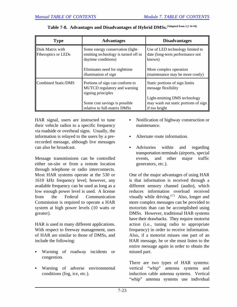
Table 7-8. Advantages and Disadvantages of Hybrid DMSs.(Adapted from 1,2 14-16)
Type Advantages Disadvantages
Disk Matrix with Some energy conservation (light- Use of LED technology limited toFiberoptics or LEDs emitting technology is turned off in date (long-term performance not
daytime conditions) known)
Eliminates need for nighttime More complex operationillumination of sign (maintenance may be more costly)
Combined Static/DMS Portions of sign can conform to Static portions of sign limitsMUTCD regulatory and warning message flexibilitysigning principles
Some cost savings is possible may wash out static portions of signrelative to full-matrix DMSs if too bright
Light-emitting DMS technology
HAR signal, users are instructed to tune C Notification of highway construction ortheir vehicle radios to a specific frequency maintenance.via roadside or overhead signs. Usually, theinformation is relayed to the users by a pre- C Alternate route information.recorded message, although live messagescan also be broadcast. C Advisories within and regarding
Message transmissions can be controlled events, and other major trafficeither on-site or from a remote location generators, etc.).through telephone or radio interconnects.Most HAR systems operate at the 530 or One of the major advantages of using HAR1610 kHz frequency level; however, any is that information is received through aavailable frequency can be used as long as a different sensory channel (audio), whichlow enough power level is used. A license reduces information overload received
from the Federal Communication visually while driving. Also, longer andCommission is required to operate a HAR more complex messages can be provided tosystem at high power levels (10 watts or motorists than can be accomplished usinggreater). DMSs. However, traditional HAR systems
HAR is used in many different applications. action (i.e., tuning radio to appropriateWith respect to freeway management, uses frequency) in order to receive information.of HAR are similar to those of DMSs, and Also, if a motorist misses one part of aninclude the following: HAR message, he or she must listen to the
C Warning of roadway incidents or missed part. congestion.
C Warning of adverse environmental vertical “whip” antenna systems andconditions (fog, ice, etc.). induction cable antenna systems. Vertical
transportation terminals (airports, special
(17)
have their drawbacks. They require motorist
entire message again in order to obtain the
There are two types of HAR systems:
“whip” antenna systems use individual
Manual TABLE OF CONTENTS Module 7. TABLE OF CONTENTS
7-24
antennas or a series of antennas C Interference with other radio systems inelectronically connected together to transmit the area is minimized. information. The signal radiates from theantenna in all directions providing a circular Disadvantages of induction cable HARarea of transmission. Vertical antenna systems include the following:systems have the following advantages:
C They are small. expensive to purchase and maintain since
C They are easy to install. the desired coverage area.
C They can be placed within several C Once installed, induction cable HARhundred feet of the roadway. systems cannot be transported from one
C They are less costly to purchase andinstall than induction cable systems.
Vertical antenna systems also have the One of the disadvantages of HAR systems isfollowing disadvantages: that they require advance signing to notify
C They are subject to damage by weather, and an action by the motorist to activate andaccidents, and vandalism. receive that information. Automated
C They often require special equipment to have been proposed that require no actionsensure that the signal is stable, reliable, by the motorist to obtain radio information.and easily tuneable. These systems emit a special electronic
C Motorists can lose the HAR signal when message, which interrupts the specially-traveling through tunnels, canyons, etc. designed radio/cassette/compact disc player
Induction cable antenna systems use a cableinstalled either under the pavement or FHWA sponsored the prototypeadjacent to the roadway. This type of development and pilot testing of an AHARantenna design produces a strong but highly system in the early 1980s. However,localized signal within a short lateral distance the difficulties associated with producing and30 to 45 m (100 to 150 ft) from the cable. marketing a receiver within a price rangeInduction cable systems have the following acceptable to motorists hindered furtheradvantages: AHAR implementation. However, recent
C The signal is strong enough to provide interest in AHAR systems. Michigan isfull coverage of a multilane facility experimenting with alternative AHARwithout causing interference to other designs at this time. Meanwhile, EuropeHAR systems. has been experimenting with a version of
C Messages can be individualized by Data System [RDS] Traffic Managementdirection of travel. Channel [TMC]) for the past few years.
C Induction cable systems are more
the cable must extend the full length of
location to another.
Automated HAR (AHAR)
motorists of the availability of information,
highway advisory radio (AHAR) systems
notification signal upstream of an HAR
to broadcast the message to the motorist.
(18,19)
emphasis on ITS has sparked renewed
(20)
these types of systems (termed the Radio
This system relies on a silent data channel
Manual TABLE OF CONTENTS Module 7. TABLE OF CONTENTS
7-25
broadcast via FM from existing radio Many metropolitan areas have establishedstations. With an appropriate radio receiver, cellular “hotlines” for motorists to call in anda motorist is then able to receive information report accident information to the highwayfrom the closest or strongest FM radio signal agency. Examples include #77 and *SP.at that location. The public agency must negotiate with the(15)
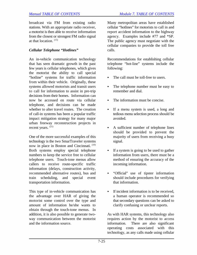
Cellular Telephone “Hotlines”
An in-vehicle communication technology Recommendations for establishing cellularthat has seen dramatic growth in the past telephone “hot-line” systems include thefew years is cellular telephones, which gives following:the motorist the ability to call special“hotline” systems for traffic information C The call must be toll-free to users.from within their vehicle. Originally, thesesystems allowed motorists and transit users C The telephone number must be easy toto call for information to assist in pre-trip remember and dial.decisions from their homes. Information cannow be accessed en route via cellular C The information must be concise.telephone, and decisions can be madewhether to alter travel routes. The creation C If a menu system is used, a long andof call-in systems has been a popular traffic tedious menu selection process should beimpact mitigation strategy for many major avoided.urban freeway reconstruction projects inrecent years. C A sufficient number of telephone lines(21)
One of the more successful examples of this majority of users from receiving a busytechnology is the two SmarTraveler systems signal.now in place in Boston and Cincinnati. (10)
Both systems employ special telephone C If a system is going to be used to gathernumbers to keep the service free to cellular information from users, there must be atelephone users. Touch-tone menus allow method of ensuring the accuracy of thecallers to receive route-specific traffic incoming information.information (delays, construction activity,recommended alternative routes), bus and C “Official” use of tipster informationtrain scheduling, and special event should include procedures for verifyingtransportation information. that information.
This type of in-vehicle communication has C If incident information is to be received,the advantage over HAR of giving the a human operator is recommended somotorist some control over the type and that secondary questions can be asked toamount of information he/she wants to clarify confusing or unclear reports.obtain through the touch-tone menus. Inaddition, it is also possible to generate two- As with HAR systems, this technology alsoway communication between the motorist requires action by the motorist to accessand the information source. information. There are also significant
cellular companies to provide the toll freecalls.
should be provided to prevent the
operating costs associated with thistechnology, as any calls made using cellular

Manual TABLE OF CONTENTS Module 7. TABLE OF CONTENTS
7-26
telephones must be paid for by either the and cooperation between themselves and themotorist, or a public agency, or else media traffic reporters. For example, someabsorbed by the corporation providing agencies allow private traffic reportingcellular telephone communication agencies to place personnel in the trafficcapabilities in the region. Finally, there is management center to obtain information onsome concern that cellular telephone usage traffic conditions and expected agencywhile driving may degrade motorist attention responses in an accurate and timely manner.and operating capabilities. Manufacturershave developed “hands-free” telephones thatallow motorists to listen and talk withoutholding the telephone receiver. Even though it was once considered an
Commercial Radio
The public has learned to depend upon the popularity in recent years. However, theremedia to provide them with “almost” real- are still a significant number of vehicles,time traffic information. Commercial radio particularly commercial vehicles and trucks,has proven to be a good means of providing equipped with CB radios. In the past, CBtravelers with traffic information both in and radios have been used primarily in motorist-out of their vehicles. Traffic and roadway aid systems. A disabled or passing travelercondition reports have become standard broadcasts a request for assistance onprogramming items on many commercial channel 9. The channel is monitored 24radio stations. Commercial radio has the hours a day, 7 days a week by a police orbest potential of reaching the greatest volunteer organization, which dispatches aidnumber of commuters, since most of them to the stranded traveler. The primaryhave radios in the vehicles they drive to and advantage of a CB radio system is that itfrom work. permits two-way communication between
The primary disadvantage of using effective range of many CB radios iscommercial radio relates to the accuracy of approximately 32 kms (20 mi), dependingthe information. Traffic reports often are upon geographic conditions. transmitted only when normal schedulingpermits. This may cause considerable timedelays between when an incident occurs andwhen it is reported by the media. Often,many incidents go unreported or are clearedby the time they are reported on the radioand television. The accuracy of the One of the newer technologies forinformation provided by commercial radio is communicating with motorists in theira function of the time between the vehicles is through a video display terminalbroadcaster’s last communication with the (VDT) mounted in the dashboard. This isincident reporting source and the number of primarily a private sector industry, which hasincidents that have occurred and/or have not been used widely for informationbeen cleared during that time. distribution. These systems can be used to
Some transportation agencies have made navigational information in one of twosubstantial efforts to improve coordination different formats. One approach is to
Citizen-Band Radio
excellent means of providing motorists withtwo-way communications from their vehicle,Citizen-Band (CB) radio has declined in
the traveler and the response agency. The
Visual In-vehicle InformationTechnologies
Video Display Terminals
provide motorists with route guidance and

Manual TABLE OF CONTENTS Module 7. TABLE OF CONTENTS
7-27
present the driver navigation and route C VDTs may also add to the visual clutterguidance information in the form of maps or already inside the vehicle.equivalent displays. With these systems, aglobal picture of the traffic network can beprovided. Recommended routes can behighlighted on the video map display as well. As technology continues to improve, theIn another approach, simple symbolic signals Head-Up Display (HUD) has become(e.g., arrows, text instructions, or a another alternative to in-vehicle VDTs forcombination of both) guide the driver along presenting visual navigational and routea recommended route. Some prototype guidance information to motorists.systems use a variety of displays depending Although originally developed for theupon whether or not the vehicle is in motion, aviation industry, several automobilethe functions selected, and level of manufacturers are beginning to developinformational and navigational displays HUDs for presenting vehicle status andavailable. navigational information to drivers.
In-vehicle VDTs offer a number of A wide variety of options for displayingadvantages over available technologies in information may be available using HUDs.providing information to motorists while Through both icons and alpha-numeric text,driving. These include the following: navigation and route guidance information
C Travel information is more readily field of view. This is expected to reduce theaccessible to the driver (providing need for visual scanning between twocontinuous access to current position, information sources (the inside instrumentrouting, and navigational information). panel and the outside environment), and the
C Computer-generated navigational mapsand displays are logical extensions of However, as might be expected, numeroustraditional forms of providing drivers concerns exist regarding the safety andwith route guidance and navigation applicability of using HUDs in the drivinginformation. environment. Currently, most HUDs
Information can be displayed in text, provide drivers with only relatively simplegraphics, or both and tailored to the needs information, such as speed indications.and desires of each motorist.
There are also limitations to in-vehicleVDTs. These include the following: The final type of information systems
C Drivers have to take their eyes off the drivers access off-roadway, at their homes,roadway in order to receive the offices, shopping malls, etc. A major thrustinformation. of ITS development and implementation
C In-vehicle VDTs present the driver with hands of motorists and passengers so as tocomplex maps and diagrams that may improve departure time, mode choice, andcreate a potential to overload the driver route choice decisions. This emphasis haswith too much information. resulted in increased utilization of a number
Head-Up Displays
may be projected directly into the driver’s
associated visual accommodation time.
(23)
under development and implementation
OFF-ROADWAY INFORMATION
discussed in this module are those that
focuses on putting more information into the

Manual TABLE OF CONTENTS Module 7. TABLE OF CONTENTS
7-28
of traditional information technologies, and displays accompanied by voice messages canhas yielded a number of new off-roadway be used to provide users with information.information sources and several new Traffic reports can also be provided bydissemination technologies. Off-roadway interrupting normal programming. Theinformation dissemination technologies primary disad-vantage of using public accessinclude the following: television is that the information is available
C Television. outside the service area or not subscribing to
C Telephones. access to the information.
C Pagers. One freeway traffic management center in
C Personal Data Assistants (PDAs). provide video and digital data directly to
C Computers. video, a computerized map display, and
C Kiosks. being implemented (which DMSs have been
Television
Television (together with radio) was one of signal. This is believed to reduce the needthe first off-roadway motorist information for censoring the images that are beingtechnologies available to motorists. Even presented, since they are not available to thetoday, commercial television stations in most public at large. major cities provide traffic reports toviewers as part of their morning programs toindicate incident locations, traffic signalmalfunctions, and other traffic “hotspots.” As discussed earlier, telephone “hotlines”These locations are usually shown on some can allow both freeway and transit users totype of wall-mounted or computer-generated obtain pre-trip information via theirmap display. telephones at home or work, or in their car
Public access television is a means of charges to call the hotline. Information canovercoming many of the disadvantages be provided using recorded messages,associated with privately owned media synthesized voice messages, or humanstations. Many city governments are operators. A touch-tone menu system canresponsible for franchising cable television be used to tailor information to a specificservice within the corporate limits of the route or travel corridor. Telephone calls arecity. As part of awarding the franchise to a also a means of developing real-timecompany, many city governments offer their rideshare matching systems that are beingown programming on one or more of these explored in several U.S. locations.dedicated channels. Public access channelscan be used by traffic management agenciesto broadcast continuous traffic informationduring peak hours. Either “crawl” messages A more recent technology now used to helpacross the bottom of the screen or map disseminate travel information to users away
only to cable subscribers. Travelers living
the particular cable company do not have
the U.S. has developed the capabilities to
television signals. They broadcast live(12)
current control and management actions
activated). These signals are scrambled sothat only those with the appropriate softwareand hardware can properly receive the
Telephones
if they are willing to pay for cellular airtime
Pagers

Manual TABLE OF CONTENTS Module 7. TABLE OF CONTENTS
7-29
from the vehicle are personal pagers. In disseminate information to travelers. AsBellevue, Washington (east of Seattle), with PDAs, two-way communicationsalphanumeric pagers provide their owners between the computer user and the travelwith hourly information regarding available information center can be established bycarpools looking for riders as well as current telephone modem or an RF communicationtraffic conditions on the Puget Sound-area link. This two-way flow of informationfreeway system. The Genesis project of allows the user to request information(24)
the ITS Guidestar program in Minneapolis, specifically tailored to his or her needs (routeMinnesota and TRANSCOM in New Jersey planning, traffic information on specificalso utilize alphanumeric pager technology roadway links, transit bus schedule andto disseminate travel conditions in real-time status, etc.).to its owners. A key constraint of pagertechnology is that broadcast messages arelimited to a small number of characters.Consequently, efforts are underway to The last off-roadway information dissem-determine which information is most relevant ination device to be discussed is theto pager owners and how to format that information kiosk. Kiosks are videoinformation succinctly, but accurately. monitors mounted on a stand-alone cabinet,(25)
Personal Data Assistants (PDAs)
Personal Data Assistants (PDAs) are the serve as an important point of access tonext higher level of sophistication in off- travel information networks in a variety ofroadway information dissemination public locations, including the following:technology. PDAs are computer productsthat have enough power to support C Hotels.applications such as time management andhandwriting recognition. By adding radio C Restaurants.frequency (RF) communications technology,PDAs allow users to interact directly with C Airports.travel information systems. This interactionallows users to obtain route planning C Gas stations (truck stops).assistance, traffic information broadcasts,and other pertinent information. Through C Retail establishments (shopping malls).keypad entry, the user can log on to theinformation system, request pertinent Kiosks are one type of informationinformation, and then log off. PDAs offer dissemination technology wherethe user increased communication and private/public partnerships are particularlyinformation transmission/receiving power relevant. For instance, some agencies areover alphanumeric pagers. However, they looking to the private sector (throughare more complex to use and expensive to advertising revenue) to help defray thepurchase. operating and maintenance costs of these (25)
Computers (Internet)
Personal computers, both desktop and where they can draw attention and reachlaptop/notebook, can also be used to their intended market.
Kiosks
in a wall, or on a counter-top. They mayhave input devices such as keypads, track-balls, or touch-screen displays. Kiosks can
systems. Proper kiosk placement is(26, 27)
also a critical issue. Many kiosks are notwell utilized because they are not located
(27)

Manual TABLE OF CONTENTS Module 7. TABLE OF CONTENTS
7-30
7.4 LESSONS LEARNED
NTCIP STANDARDS
Equipment compatibility, especially withrespect to communications, has long been aproblem for many transportation agenciesoperating various components of freewaymanagement systems. Incompatibilitiesbetween DMS and HAR hardware fromdifferent vendors have required the agencyto have separate systems to communicatewith each type of DMS or HAR. This hasmade it difficult to operate the equipmentefficiently and in an integrated manner.
In response to these and other problems, aNational Transportation CommunicationsInterface Protocol (NTCIP) is underdevelopment to reduce the difficultiesassociated with developing an integratedfreeway management system. Theseprotocols establish standard communicationslinkages between various types of hardwareand software used for traffic managementpurposes. This ultimately reduces the needfor an agency to select and stay with aparticular vendor or model of equipment.
In the information dissemination arena,standards have been proposed, or are underdevelopment, for DMS and for HAR.Standards for other equipment are likely toemerge as the need arises. Partners arestrongly encouraged to utilize NTCIPstandards where possible.
INFORMATION MESSAGE DESIGN
Although traditionally a concern associatedwith public agency information disseminationmechanisms such as DMS and HAR, theproper design and packaging of theinformation being disseminated is critical tosuccessfully meeting the goals and objectivesfor all components of an information
dissemination subsystem. Evidence alreadyexists on some of the newer ATIStechnologies that improper message designshave an adverse impact upon customer (i.e.,motorist) interpretation of the worth andusefulness of these technologies. (29)
Without proper attention to packaging, theintended audience may not be able toadequately perceive, interpret, and respondto the information. The following factorsare critical to proper message design:
C Message load.
C Message length.
C Message format.
Message load refers to the quantity ofinformation that is included in a givenmessage. Message load is an importantconsideration for DMS operations, becausethe driver must attend to many differenttasks at the same time, while trying to readand comprehend a message. If the messagepresents too much information, messageoverload may occur. Some transportationagencies have reported traffic slowing downand other adverse operational problems inthe vicinity of DMSs when messages are toolong. (1)
Message length refers to the number ofwords or characters that are displayed onone or more lines of a sign or sequence.Obviously, message length and load arerelated. However, message length and howthe message is formatted, or “chunked,”both affect message load.
Message formatting is a term that refers tothe arrangement of message elements (wordsor lines) on an information disseminationdevice (e.g., a sign) to form a message. Useof abbreviations also relates to messageformatting. Placement of message elementson the wrong line or in the wrong sequence

Manual TABLE OF CONTENTS Module 7. TABLE OF CONTENTS
7-31
will result in confusion and increased large extent by a regular sign maintenancemessage reading and comprehension times. (pixel lens cleaning, light bulb replacement)
program.The completed and detailed set of guidelinesregarding message design from which theseparagraphs were drawn are availableelsewhere. Another DMS-specific issue is what to do (2)
ENVIRONMENTAL ISSUESCONCERNING DMSs
Because they are located outdoors next to dissemination devices. One perspective isthe freeway, the effectiveness of DMSs as an that some type of information such asinformation source is also affected by current time and temperature, an agencyenvironmental factors. Two factors that can slogan, etc., should be provided at all times.be significant are sun position and Proponents argue that this indicates toweathering effects. motorists that the devices are working. The
Sun Position
Both sunlight falling directly upon the face thought argue that, according to humanof a DMS and sunlight located directly factors principles, trivial or non-trafficbehind the DMS adversely affect a driver’s specific information should be avoided soability to see the message. Sign positions that the devices do not lose credibility withwith the rear surfaces oriented west- the travelers.southwest and east-northeast shouldtherefore be avoided if possible. The west-southwest orientation is more problematic,however, because the setting sun tends to bemore intense than the rising sun.(1)
Weathering
Because of their proximity to freeway travellanes, road grime can be a problem forcertain DMSs, and significantly reduce thedistances at which they are legible.Consequently, DMS manufacturers oftenplace clear Lexan covers over the DMS faceto protect the sign from road grime andother environmental effects. One studysuggests that legibility distances of a fixed-grid fiberoptic DMS (a freeway lane controlsignal without a Lexan cover) may bereduced by as much as 25 percent after 18months in the field. It appears that these(29)
losses in legibility can be minimized to a
“AT-REST” DISPLAY CONDITIONS
with the signs when there is nothing specialto report to travelers. There are generallytwo schools of thought regarding wheninformation should be provided in
(2)
other perspective is to display informationonly when there is something new to telltravelers. Proponents of this school of
7.5 EXAMPLE OF ANINFORMATION DISSEMINATION SYSTEM:TRANSCOM
ORGANIZATION
TRANSCOM (Transportation OperationsCoordinating Committee) is a consortium of14 transportation and public safety agenciesin the New York, New Jersey, andConnecticut area whose goal is to provide acooperative, coordinated approach toregional traffic management. TRANSCOMis funded, staffed, and governed by itsmember agencies. It has an OperationsInformation Center (OIC) that is staffed 24hours per day, 7 days per week.TRANSCOM shares incident information via

Manual TABLE OF CONTENTS Module 7. TABLE OF CONTENTS
7-32
alphanumeric pager, phone, and fax to more dissemination and incident response in thethan 200 highway and transit facilities, police region. These include the following:agencies, and radio traffic services. It alsoserves as a forum for incident and special C Regionwide initiatives for coordinatedevent management planning, construction deployment and operation of VMSs,coordination, and for shared testing and HAR, and enhanced traffic monitoringimplementation of regional traffic and via CCTV.transportation management technologies.
The planning process for TRANSCOM system at the intersection of the Newbegan at the end of 1984. TRANSCOM Jersey Turnpike and Garden Statebegan operations in 1986. Originally, the Parkway, which will focus on alternativePort Authority of New York envisioned routing for New Jersey transit buses. TRANSCOM as a coordinating mechanismto facilitate traffic flow and operations at the C Expansion of traffic monitoring alongHudson River crossings. However, the I-287 Tappan Zee Bridge corridor.TRANSCOM’s focus quickly expanded to C Initiation of the TRANSMITall traffic facilities in the region. (TRANSCOM’s System for Monitoring
TRANSCOM is managed by a steering This project uses vehicles withcommittee made up of senior and mid-level transponders on a highway systemmanagers from each agency. This committee equipped with readers/antennas.directs the technical and operational focus ofTRANSCOM. Meanwhile, an executive TRANSCOM receives information regardingcommittee consisting of the chief executive incidents and transit facility conditions fromofficer from each agency decides major all over the area. The OIC is normallypolicies pertaining to TRANSCOM. staffed with two operators who receive,
Although TRANSCOM is a public sector related information. The information isinformation dissemination example, it is relayed to the agencies affected by theconsidering moving towards a public/private incident via alphanumeric pagers, facsimilepartnership. Public/private partnerships are machines, and voice communications. Thisa much more appropriate example of what is information is then disseminated by thelikely to occur in the future. various agencies according to their
OPERATIONS
The TRANSCOM OIC receives information technologies for certain agencies.regarding incidents and transit facilities fromall over the metropolitan area. The TRANSCOM operations are fully funded byoperations personnel in the OIC are its member agencies. This funding consistsemployees of one of the member agencies of both monetary contributions and in-kindand generally have some background in services such as providing operators to staffdispatch, operations, or media reporting. the OIC. The TRANSCOM partnership has allowedseveral projects to be developed andimplemented to facilitate information
C An enhanced traffic advisory/diversion
Incidents and Traffic) Operational Test.
collate, and disseminate transportation-
capabilities. In some instances,TRANSCOM has been granted authority tooperate the information dissemination
(9)

Manual TABLE OF CONTENTS Module 7. TABLE OF CONTENTS
7-33
FUTURE ACTIVITIES
The executive and steering committees are is an example of this commitment to futurelooking at a number of issues relating to operations. TRANSCOM is participatingfuture TRANSCOM operations. with other agencies in the development of aTRANSCOM will continue to pursue computerized Information Exchangeresearch and testing of advanced Network (IEN) to automate the informationtechnologies to help the region more retrieval and dissemination process.
effectively manage travel in the congestednortheast corridor. The TRANSMIT system
(30)


Manual TABLE OF CONTENTS Module 7. TABLE OF CONTENTS
7-35
7.6 REFERENCES
1. Dudek, C.L. Guidelines on the Use of Changeable Message Signs. Report No. FHWA-TS-90-043. FHWA, U.S. Department of Transportation, Washington, DC, May 1991.
2. Dudek, C.L. and Huchingson, R.D. Manual on Real-Time Motorist InformationDisplays. Report No. FHWA-IP-86-016. FHWA, U.S. Department of Transportation,Washington, DC, August 1986.
3. Inman, V., Sanchez, R., Porter, C., and Bernstein, L. TravTek Evaluation Yoked DriverStudy. Report No. FHWA-RD-94-139. FHWA, U.S. Department of Transportation,Washington, DC, October 1995.
4. Building the ITI: Putting the National Architecture into Action. Report No. FHWA-JPO-96-011. FHWA, U.S. Department of Transportation, Washington, DC, April 1996.
5. Vorce, K.E. and Plass, M. A Practical Approach to Changeable Message Sign SystemDesign and Deployment: The I-595 Experience in South Florida. Proceedings, Third ITSWorld Conference, Orlando, FL, October 1996.
6. Implementation Plan Guidance (23 CFR 655 409). Federal-Aid Policy Guide. FHWA,U.S. Department of Transportation, Washington, DC, December 1994.
7. McGowan, P.F., Olson, M.D., and Irwin, P.L. Texas Department of TransportationAdvanced Traffic Management System, San Antonio, Texas. Compendium of TechnicalPapers, 64th Annual Meeting of the Institute of Transportation Engineers, Dallas, TX,October 1994, pp 1-9.
8. Roper, D.H., Murphy, R.J., and Zimowski, R.F. Alternative Route Planning: SuccessfulIncident Traffic Management. Special Report No. 153, TRB, National Research Council,Washington, DC, 1975, pp 141-144.
9. Wilson, F.J. The TRANSCOM Coalition: Multi-Jurisdictional Issues in ITS. ITSQuarterly, Vol. IV, No. 2, Spring 1996, pp 83-95.
10. Bregman, S., Koses, D.G., and Wilson, A.P. Targeting the Car Phone Market: Findingsfrom a Survey of Callers Using Cellular Telephones to Access the SmarTravelerAdvanced Traveler Information System. Proceedings, Third ITS World Conference,Orlando, FL, October 1996.
11. Dial and Drive -- or Don’t. Inside IVHS, Vol. 5, No. 3, January 30, 1995.
12. Dellenback, S.W., and McGowan, P.F. Advanced Traveler Information Systems UsingLow Power Television Stations. Proceedings, 1996 Annual Meeting of ITS America,Houston, TX, April 1996, pp 82-86.
Manual TABLE OF CONTENTS Module 7. TABLE OF CONTENTS
7-36
13. Ullman, G.L., Wohlschlaeger, S.D., Dudek, C.L., and Wiles, P.B. Driver Interpretationsof Existing and Potential Lane Control Signal Symbols for Freeway TrafficManagement. Report No. FHWA/TX-93/1298-1, Texas Transportation Institute,College Station, TX, November 1993.
14. Dudek, C.L. Changeable Message Signs. NCHRP Synthesis of Highway Practice No.61. TRB, National Research Council, Washington, DC, 1979.
15. Gordon, R.L., Reiss, R.A., Haenel, H., Case, E. R., French, R.L., Mohaddes, A., andWolcott, R. Traffic Control Systems Handbook. Report No. FHWA-SA-95-032.FHWA, U.S. Department of Transportation, Washington, DC, February 1996.
16. Lavigne, R.C. Assessment of Changeable Message Sign Technology. Report No.FHWA/RD-87/025. FHWA, U.S. Department of Transportation, Washington, DC,December 1986.
17. Walker, J., Alicandri, E., Sedney, C., and Roberts, K. In-vehicle Navigation Devices:Effects on the Safety of Driver Performance. Report No. FHWA-RD-90-053. FHWA,U.S. Department of Transportation, Washington, DC, May 1990.
18. Automatic Audio Signing, Volume I: Executive Summary. Report No. FHWA/RD-82/012. FHWA, U.S. Department of Transportation, Washington, DC, November 1981.
19. Turnage, H.C., Hawthorne, R.C., and Birdseye, M.C.L. Automatic Audio Signing,Volume II: Prototype Development and Prototype Pilot Testing Demonstration Program.Report No. FHWA/RD-84/039. FHWA, U.S. Department of Transportation,Washington, DC, June 1984.
20. Rajendra, K., and Maki, R.E. The IVHS Strategy in Michigan. Proceedings of the IVHSAmerica Annual Meeting, Atlanta, GE, April 1993, pp 402-406.
21. Von Tomkewitsch, R. Dynamic Route Guidance and Interface Transport Managementwith ALI-SCOUT. IEEE Transactions on Vehicle Technology, Vol. 40, No. 1, February1991.
22. Dingus, T.A., Carpenter, J.T., et al. Human Factors Engineering the TravTek DriverInterface. Vehicle Navigation and Information Systems Conference Proceedings, ReportNo. SAE/P-91/253, Society of Automotive Engineers, Inc., Warrendale, PA, October1991, pp 749-756.
23. Kiefer, R.J. A Review of Driver Performance with Head-Up Displays. Proceedings,Third ITS World Conference, Orlando, FL, October 1996.
24. Haselkorn, M., Spyridakis, J., Gable, B., and Michalak, S. Bellevue Smart Traveler: AnIntegrated Phone and Pager System for Downtown Dynamic Ride Sharing. Proceedingsof the IVHS America Annual Meeting, Atlanta, GE, April 1993, pp 126-131.
Manual TABLE OF CONTENTS Module 7. TABLE OF CONTENTS
7-37
25. Starr, R.A., and Wetherby, B.C. Traffic Information on Alphanumeric Pagers: EvaluationResults from the Genesis Project. Proceedings, Third ITS World Conference, Orlando,FL, October 1996.
26. Schroeder, J.L., and Green, J. The Emergence of Smart Traveller Kiosk and the UserInterface Requirments for their Successful Deployment. Proceedings of the IVHSAmerica Annual Meeting, Atlanta, GE, April 1993, pp 831-837.
27. Pohlman, J.M., and Long, T.I. Advanced Traveler Information Project Travelink. Proceedings, Third ITS World Conference, Orlando, FL, October 1996.
28. Guiliano, G., Hall, R., and Golob, J.M. Los Angeles Smart Traveler Field OperationalTest Evaluation. Report No. UCB-ITS-RRR-95-41. California PATH Program, Instituteof Transportation Studies, University of California-Berkeley, Berkeley, CA, December1995.
29. Ullman, G.L., Tallamraju, S.S., and Trout, N.D. Visibility and Spacing of Lane ControlSignals for Freeway Traffic Management. Report No. FHWA/TX-95/1498-1. TexasTransportation Institute, College Station, TX, November 1994.
30. Tarnoff, P.J., and Batz, T. The TRANSCOM TRANSMIT Project: A UniqueInstitutional Approach to a Unique Project. Proceedings of the IVHS America AnnualMeeting, Atlanta, GE, April 1993, pp 233-237.