Embed Size (px)
Citation preview

DOE Fundamentals
ENGINEERING SYMBOLOGY, PRINTS, AND DRAWINGS
Module 6
Engineering Fabrication, Construction, and Architectural
Drawings
Engineering Symbology, Prints, & Drawings Engineering Fabrication, Construction, & Architectural Drawings
i
TABLE OF CONTENTS
Table of Co nte nts
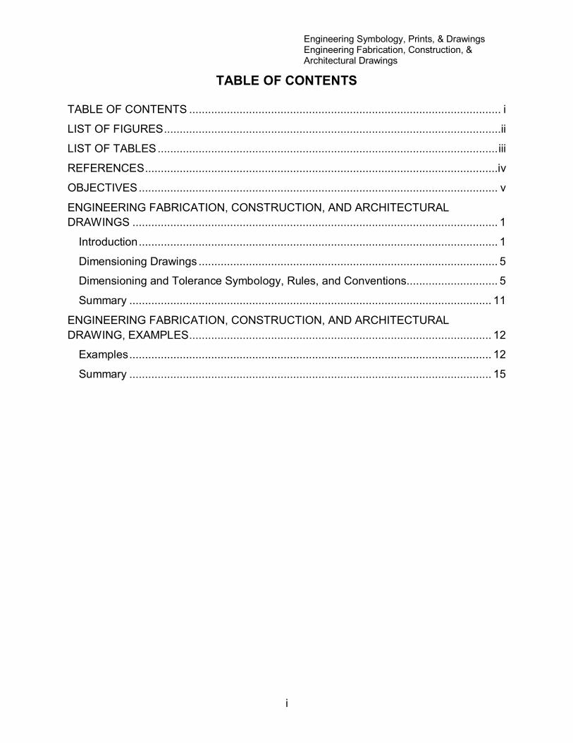
TABLE OF CONTENTS ................................................................................................... i
LIST OF FIGURES ...........................................................................................................ii
LIST OF TABLES ............................................................................................................ iii
REFERENCES ................................................................................................................iv
OBJECTIVES .................................................................................................................. v
ENGINEERING FABRICATION, CONSTRUCTION, AND ARCHITECTURAL
DRAWINGS .................................................................................................................... 1
Introduction .................................................................................................................. 1
Dimensioning Drawings ............................................................................................... 5
Dimensioning and Tolerance Symbology, Rules, and Conventions............................. 5
Summary ................................................................................................................... 11
ENGINEERING FABRICATION, CONSTRUCTION, AND ARCHITECTURAL
DRAWING, EXAMPLES ................................................................................................ 12
Examples ................................................................................................................... 12
Summary ................................................................................................................... 15
Engineering Symbology, Prints, & Drawings Engineering Fabrication, Construction, & Architectural Drawings
ii
LIST OF FIGURES
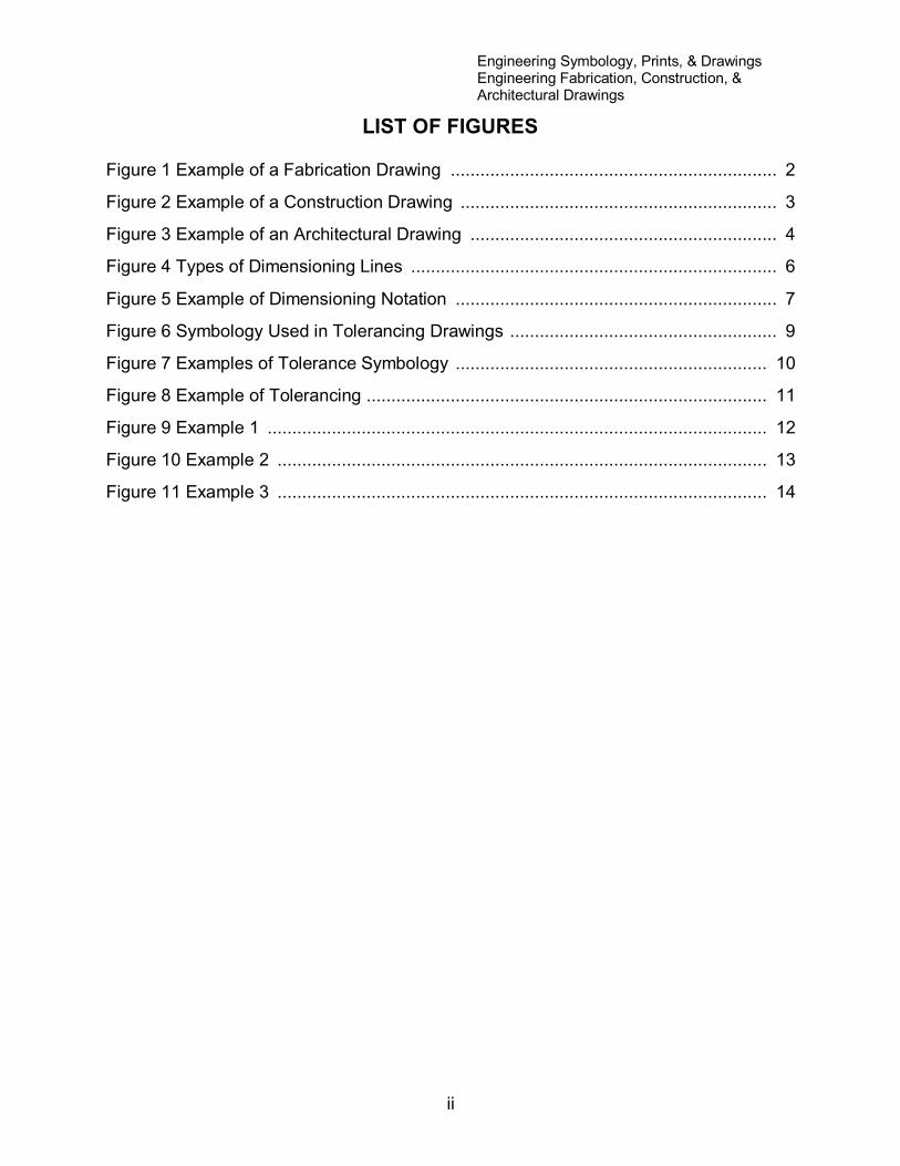
Figure 1 Example of a Fabrication Drawing .................................................................. 2
Figure 2 Example of a Construction Drawing ................................................................ 3
Figure 3 Example of an Architectural Drawing .............................................................. 4
Figure 4 Types of Dimensioning Lines .......................................................................... 6
Figure 5 Example of Dimensioning Notation ................................................................. 7
Figure 6 Symbology Used in Tolerancing Drawings ...................................................... 9
Figure 7 Examples of Tolerance Symbology ............................................................... 10
Figure 8 Example of Tolerancing ................................................................................. 11
Figure 9 Example 1 ..................................................................................................... 12
Figure 10 Example 2 ................................................................................................... 13
Figure 11 Example 3 ................................................................................................... 14

Engineering Symbology, Prints, & Drawings Engineering Fabrication, Construction, & Architectural Drawings
iii
LIST OF TABLES
NONE
Engineering Symbology, Prints, & Drawings Engineering Fabrication, Construction, & Architectural Drawings
iv
REFERENCES
ASME Y14.5-2009, Dimensioning and Tolerancing.
IEEE Std 315-1975 (Reaffirmed 1993), Graphic Symbols for Electrical and
Electronic Diagrams.
Gasperini, Richard E., Digital Troubleshooting, Movonics Company; Los Altos,
California, 1976.
Jensen - Helsel, Engineering Drawing and Design, 7th Ed., McGraw-Hill Book
Company, New York (August 15, 2007).
Lenk, John D., Handbook of Logic Circuits, Reston Publishing Company, Reston,
Virginia, 1972.
Wickes, William E., Logic Design with Integrated Circuits, John Wiley & Sons,
Inc, 1968.
Naval Auxiliary Machinery United States Naval Institute, Annapolis, Maryland,
1951.
TPC Training Systems, Reading Schematics and Symbols, Technical Publishing
Company, Barrington, Illinois, 1974.
Arnell, Alvin, Standard Graphical Symbols, McGraw-Hill Book Company, 1963.
George Masche, Systems Summary of a Westinghouse Pressurized Water
Reactor, Westinghouse Electric Corporation, 1971.
Smith-Zappe, Valve Selection Handbook, 5th Ed., Gulf Publishing Company,
Houston, Texas, December 2003.
Engineering Symbology, Prints, & Drawings Engineering Fabrication, Construction, & Architectural Drawings
v
OBJECTIVES
TERMINAL OBJECTIVE
1.0 Given an engineering fabrication, construction, or architectural drawing, READ
and INTERPRET basic dimensional and tolerance symbology, and basic
fabrication, construction, or architectural symbology.
ENABLING OBJECTIVES
1.1 STATE the purpose of engineering fabrication, construction, and
architectural drawings.
1.2 Given an engineering fabrication, construction, or architectural drawing,
DETERMINE the specified dimensions of an object.
1.3 Given an engineering fabrication, construction, or architectural drawing,
DETERMINE the maximum and minimum dimensions or location of an object or
feature from the stated drawing tolerance.
Engineering Symbology, Prints, & Drawings Engineering Fabrication, Construction, & Architectural Drawings
1
ENGINEERING FABRICATION, CONSTRUCTION, AND
ARCHITECTURAL DRAWINGS
This chapter describes the basic symbology used in the dimensions and
tolerances of engineering fabrication, construction, and architectural
drawings. Knowledge of this information will make these types of prints
easier to read and understand.
EO 1.1 STATE the purpose of engineering fabrication, construction, and
architectural drawings.
EO 1.2 Given an engineering fabrication, construction, or architectural
drawing, DETERMINE the specified dimensions of an object.
EO 1.3 Given an engineering fabrication, construction, or architectural
drawing, DETERMINE the maximum and minimum dimensions or
location of an object or feature from the stated drawing tolerance.
Introduction
This chapter will describe engineering fabrication, construction, and architectural
drawings. These three types of drawings represent the category of drawings commonly
referred to as blueprints. Fabrication, construction, and architectural drawings differ
from P&IDs, electrical prints, and logic diagrams in that they are drawn to scale and
provide the component's physical dimensions so that the part, component, or structure
can be manufactured or assembled. Although fabrication and construction drawings are
presented as separate categories, both supply information about the manufacture or
assembly of a component or structure. The only real difference between the two is the
subject matter. A fabrication drawing provides information on how a single part is
machined or fabricated in a machine shop, whereas a construction drawing provides the
construction or assembly of large multi-component structures or systems.
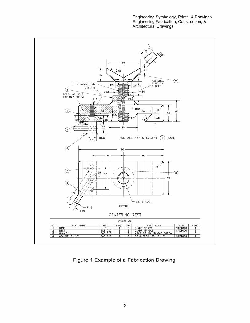
Fabrication drawings, also called machine drawings, are principally found in and around
machine and fabrication shops where the actual machine work is performed. The
drawing usually depicts the part or component as an orthographic projection (see
module 1 for definition) with each view containing the necessary dimensions. Figure 1 is
an example of a fabrication drawing. In this case, the drawing is a centering rest that is
used to support material as it is being machined.
Engineering Symbology, Prints, & Drawings Engineering Fabrication, Construction, & Architectural Drawings
2
Figure 1 Example of a Fabrication Drawing
Engineering Symbology, Prints, & Drawings Engineering Fabrication, Construction, & Architectural Drawings
3
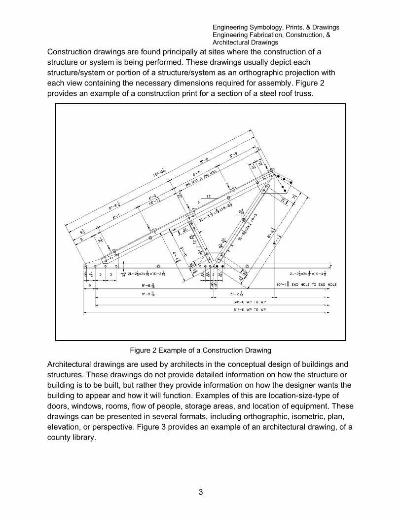
Construction drawings are found principally at sites where the construction of a
structure or system is being performed. These drawings usually depict each
structure/system or portion of a structure/system as an orthographic projection with
each view containing the necessary dimensions required for assembly. Figure 2
provides an example of a construction print for a section of a steel roof truss.
Figure 2 Example of a Construction Drawing
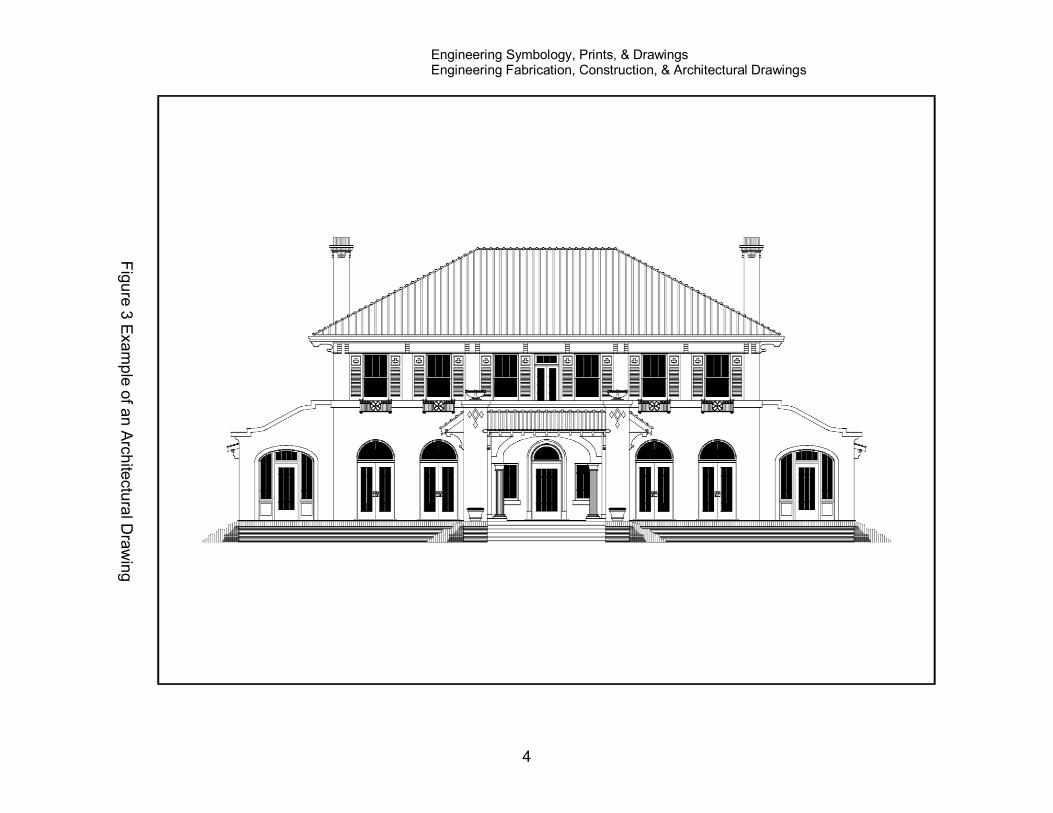
Architectural drawings are used by architects in the conceptual design of buildings and
structures. These drawings do not provide detailed information on how the structure or
building is to be built, but rather they provide information on how the designer wants the
building to appear and how it will function. Examples of this are location-size-type of
doors, windows, rooms, flow of people, storage areas, and location of equipment. These
drawings can be presented in several formats, including orthographic, isometric, plan,
elevation, or perspective. Figure 3 provides an example of an architectural drawing, of a
county library.
Engineering Symbology, Prints, & Drawings Engineering Fabrication, Construction, & Architectural Drawings
4
Fig
ure
3 E
xa
mp
le o
f an
Arc
hite
ctu
ral D
raw
ing
Engineering Symbology, Prints, & Drawings Engineering Fabrication, Construction, & Architectural Drawings
5
Dimensioning Drawings
For any engineering fabrication, construction, or architectural drawing to be of value,
exact information concerning the various dimensions and their tolerances must be
provided by the drawing. Drawings usually denote dimensions and tolerances per the
American National Standards Institute (ANSI) standards. These standards are
explained in detail in Dimensioning and Tolerancing, ANSI Y14.5M - 1982. This section
will review the basic methods of denoting dimensions and tolerances on drawings per
the ANSI standards.
Dimensions on a drawing can be expressed in one of two ways. In the first method, the
drawing is drafted to scale and any measurement is obtained by measuring the drawing
and correcting for the scale. In the second method, the actual dimensions of the
component are specified on the drawing. The second method is the preferred method
because it reduces the chances of error and allows greater accuracy and drawing
flexibility. Because even the simplest component has several dimensions that must be
stated (and each dimension must have a tolerance), a drawing can quickly become
cluttered with dimensions. To reduce this problem, the ANSI standards provide rules
and conventions for dimensioning a drawing. The basic rules and conventions must be
understood before a dimensioned drawing can be correctly read.
Dimensioning and Tolerance Symbology, Rules, and Conventions
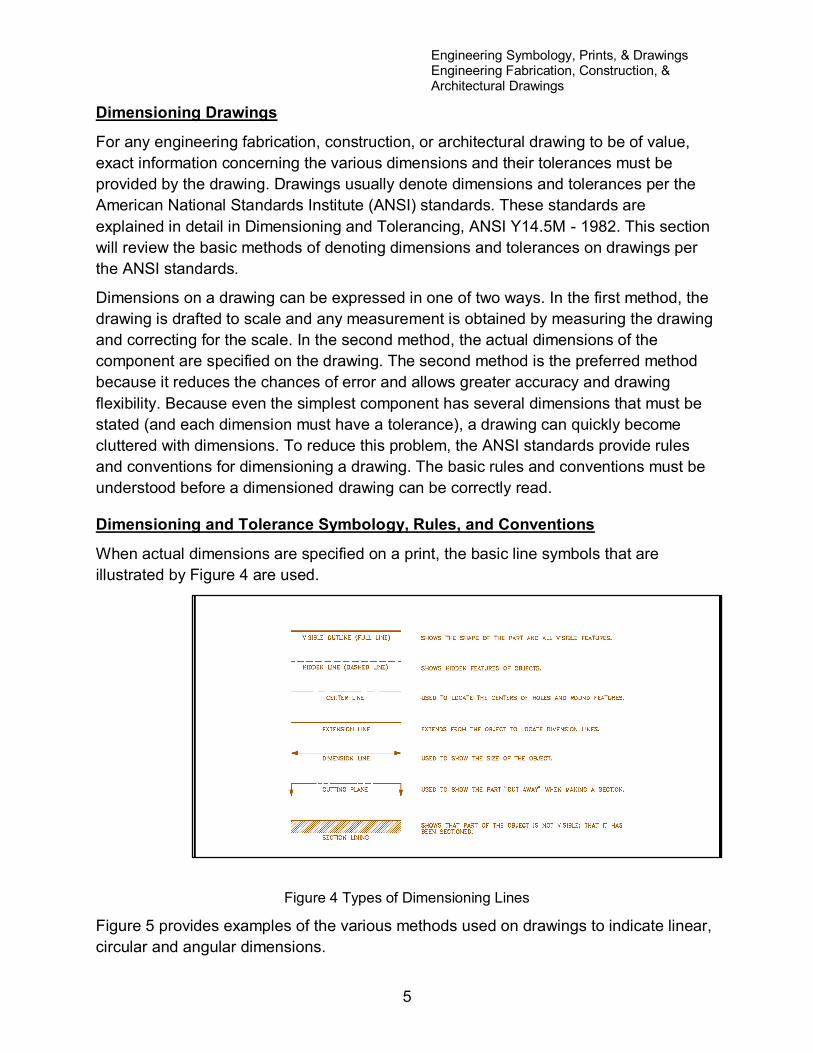
When actual dimensions are specified on a print, the basic line symbols that are
illustrated by Figure 4 are used.
Figure 4 Types of Dimensioning Lines
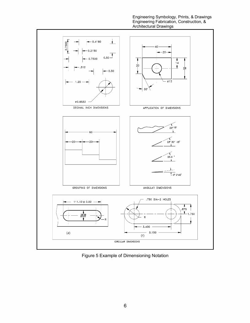
Figure 5 provides examples of the various methods used on drawings to indicate linear,
circular and angular dimensions.
Engineering Symbology, Prints, & Drawings Engineering Fabrication, Construction, & Architectural Drawings
6
Figure 5 Example of Dimensioning Notation
Engineering Symbology, Prints, & Drawings Engineering Fabrication, Construction, & Architectural Drawings
7
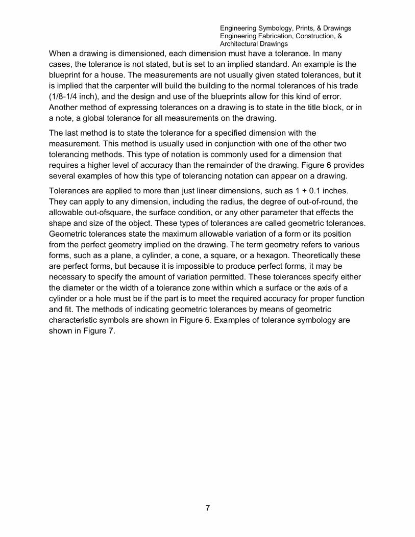
When a drawing is dimensioned, each dimension must have a tolerance. In many
cases, the tolerance is not stated, but is set to an implied standard. An example is the
blueprint for a house. The measurements are not usually given stated tolerances, but it
is implied that the carpenter will build the building to the normal tolerances of his trade
(1/8-1/4 inch), and the design and use of the blueprints allow for this kind of error.
Another method of expressing tolerances on a drawing is to state in the title block, or in
a note, a global tolerance for all measurements on the drawing.
The last method is to state the tolerance for a specified dimension with the
measurement. This method is usually used in conjunction with one of the other two
tolerancing methods. This type of notation is commonly used for a dimension that
requires a higher level of accuracy than the remainder of the drawing. Figure 6 provides
several examples of how this type of tolerancing notation can appear on a drawing.
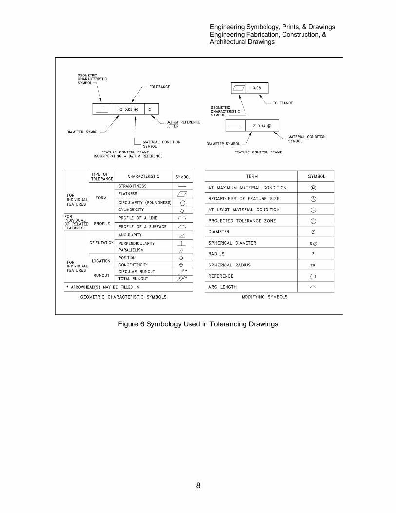
Tolerances are applied to more than just linear dimensions, such as 1 + 0.1 inches.
They can apply to any dimension, including the radius, the degree of out-of-round, the
allowable out-ofsquare, the surface condition, or any other parameter that effects the
shape and size of the object. These types of tolerances are called geometric tolerances.
Geometric tolerances state the maximum allowable variation of a form or its position
from the perfect geometry implied on the drawing. The term geometry refers to various
forms, such as a plane, a cylinder, a cone, a square, or a hexagon. Theoretically these
are perfect forms, but because it is impossible to produce perfect forms, it may be
necessary to specify the amount of variation permitted. These tolerances specify either
the diameter or the width of a tolerance zone within which a surface or the axis of a
cylinder or a hole must be if the part is to meet the required accuracy for proper function
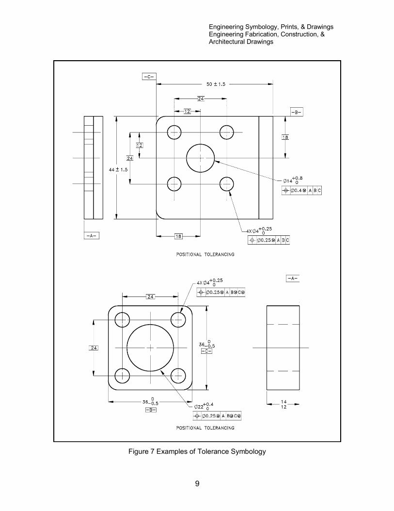
and fit. The methods of indicating geometric tolerances by means of geometric
characteristic symbols are shown in Figure 6. Examples of tolerance symbology are
shown in Figure 7.
Engineering Symbology, Prints, & Drawings Engineering Fabrication, Construction, & Architectural Drawings
8
Figure 6 Symbology Used in Tolerancing Drawings
Engineering Symbology, Prints, & Drawings Engineering Fabrication, Construction, & Architectural Drawings
9
Figure 7 Examples of Tolerance Symbology

Engineering Symbology, Prints, & Drawings Engineering Fabrication, Construction, & Architectural Drawings
10
Because tolerances allow a part or the placement of a part or feature to vary or have a
range, all of an object's dimensions cannot be specified. This allows the unspecified,
and therefore non-toleranced, dimension to absorb the errors in the critical dimensions.
As illustrated in Figure 8 (A) for example, all of the internal dimensions plus each
dimension's maximum tolerance adds up to more than the specified overall dimension
and its maximum tolerance. In this case the length of each step plus its maximum
tolerance is 1 1/10 inches, for a maximum object length of 3 3/10 inches. However the
drawing also specifies that the total length of the object cannot exceed 3 1/10 inches. A
drawing dimensioned in this manner is not correct, and one of the following changes
must be made if the part is to be correctly manufactured.
To prevent this type of conflict, the designer must either specify different tolerances for
each of the dimensions so that the length of each smaller dimension plus its maximum
error adds up to a value within the overall dimension plus its tolerance, or leave one of
the dimensions off, as illustrated in Figure 8 (B) (the preferred method).
Figure 8 Example of Tolerancing
Engineering Symbology, Prints, & Drawings Engineering Fabrication, Construction, & Architectural Drawings
11
Summary
The important information in this chapter is summarized below.
Engineering Fabrication, Construction, and Architectural Drawings Summary
The purpose of a fabrication drawing is to provide the information necessary to
manufacture and machine components.
The purpose of construction drawings is to provide the information necessary to
build and assemble structures and systems.
The purpose of architectural drawings is to provide conceptual information about
buildings and structures.
This chapter reviewed the basic symbology used in dimensioning engineering
fabrication, construction, and architectural drawings.
Engineering Symbology, Prints, & Drawings Engineering Fabrication, Construction, & Architectural Drawings
12
ENGINEERING FABRICATION, CONSTRUCTION, AND
ARCHITECTURAL DRAWING, EXAMPLES
The information presented in the previous chapter is reviewed in this
chapter through the performance of reading drawing examples.
Examples
To aid in understanding the material presented in this module, practice reading the
following prints by answering the questions. The answers are on the page following the
last example.
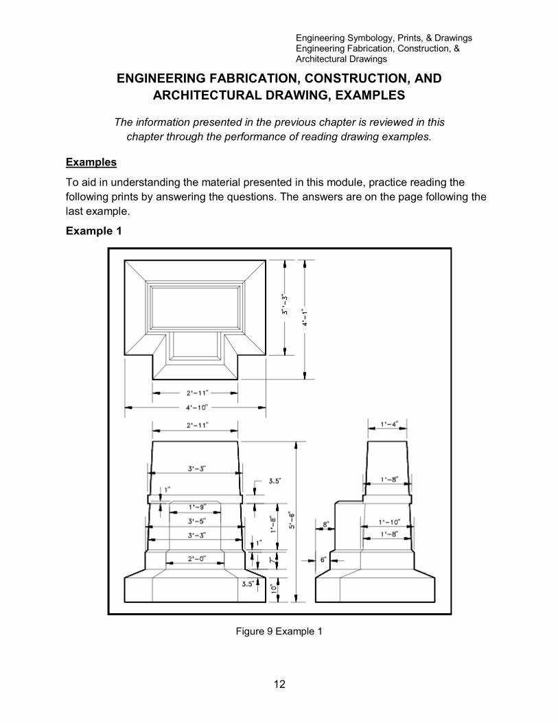
Example 1
Figure 9 Example 1
Engineering Symbology, Prints, & Drawings Engineering Fabrication, Construction, & Architectural Drawings
13
1. What is the overall height of the structure?
2. What is the width (front-to-back) of the structure?
3. What is the difference between the width (front-to-back) and the width (side-to-
side) of the base of the structure?
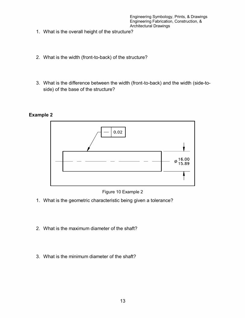
Example 2
Figure 10 Example 2
1. What is the geometric characteristic being given a tolerance?
2. What is the maximum diameter of the shaft?
3. What is the minimum diameter of the shaft?
Engineering Symbology, Prints, & Drawings Engineering Fabrication, Construction, & Architectural Drawings
14
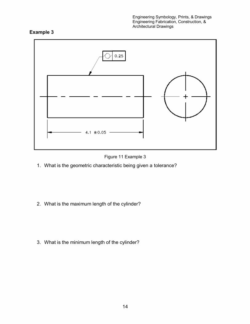
Example 3
Figure 11 Example 3
1. What is the geometric characteristic being given a tolerance?
2. What is the maximum length of the cylinder?
3. What is the minimum length of the cylinder?
Engineering Symbology, Prints, & Drawings Engineering Fabrication, Construction, & Architectural Drawings
15
Answers to example 1.
1. 5' 6"
2. 4' 1 "
3. 9" (4' 10" side-to-side distance - 4' 1" front-to-back distance)
Answers to example 2.
1. Using Figure 6, the straight line in the geometric characteristic box indicates
"straightness." This implies that the surface must be straight to within 0.02
inches.
2. 16.00 inches
3. 15.89 inches
Answers to example 3.
1. Using Figure 6, the circle with two parallel bars in the geometric characteristic
box indicates "Cylindricity," or how close to being a perfect cylinder it must be (in
this case 0.25 inches).
2. 4.15 inches. The nominal length of 4.1 plus the tolerance of 0.05.
3. 4.05 inches. The nominal length of 4.1 minus the tolerance of 0.05.
Summary
The important information in this chapter is summarized below.
Engineering Fabrication, Construction, and Architectural Drawing Exercise
Summary
This chapter reviewed the material on dimensioning and tolerancing engineering
fabrication, construction, and architectural drawings