Embed Size (px)
DESCRIPTION
Technology in radio
Citation preview
DeekshaTech
www.deekshatech.in
DEEKSHA TECH GROUP
Module 5
OFDMA and SC FDMA
Agenda Understand LTE Duplexing
Single Transmitter FDMA Principle Multi carrier principle
OFDMA and SC FDMA Principle Multipath Propagation Cyclic Prefix OFDMA and SC FDMA
Transmitter Receiver
OFDM and SC FDMA Key ParametersResource Block
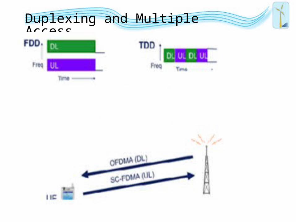
Duplexing and Multiple Access
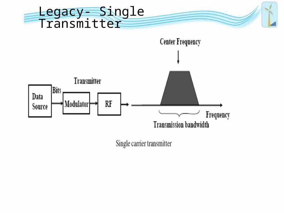
Legacy- Single Transmitter
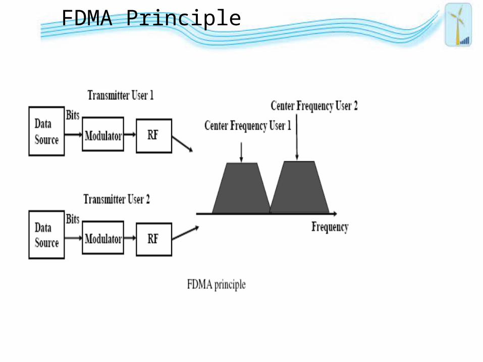
FDMA Principle
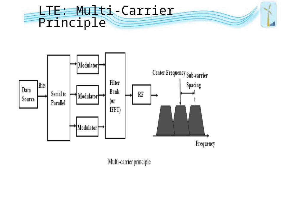
LTE: Multi-Carrier Principle
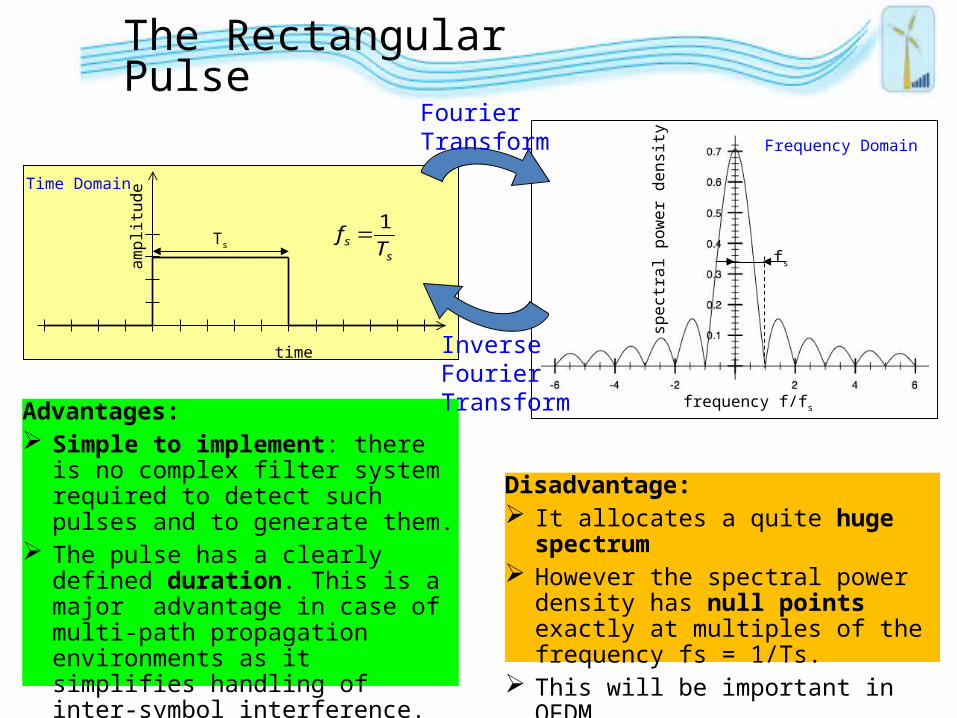
The Rectangular Pulse
Advantages: Simple to implement: there is no
complex filter system required to detect such pulses and to generate them.
The pulse has a clearly defined duration. This is a major advantage in case of multi-path propagation environments as it simplifies handling of inter-symbol interference.
Disadvantage: It allocates a quite huge spectrum However the spectral power density has
null points exactly at multiples of the frequency fs = 1/Ts.
This will be important in OFDM.
time
ampl
itude
Ts
fs 1
Ts
Time Domain
frequency f/fs
spec
tral
pow
er d
ensi
ty
Frequency Domain
fs
FourierTransform
Inverse FourierTransform
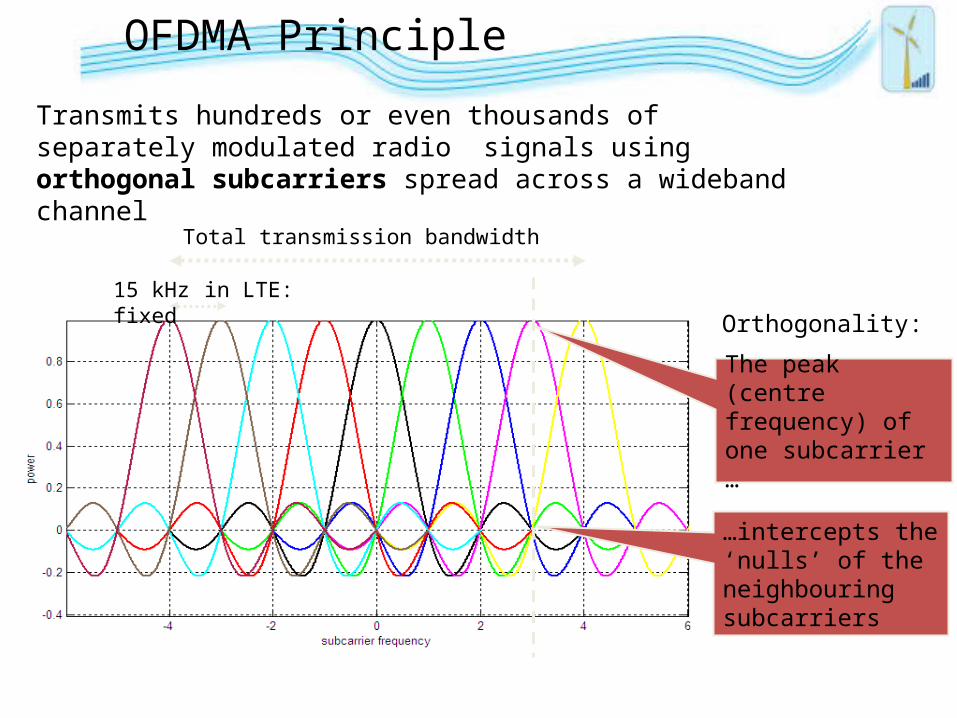
OFDMA Principle
Transmits hundreds or even thousands of separately modulated radio signals using orthogonal subcarriers spread across a wideband channel
Orthogonality:
The peak (centre frequency) of one subcarrier …
…intercepts the ‘nulls’ of the neighbouring subcarriers
15 kHz in LTE: fixed
Total transmission bandwidth
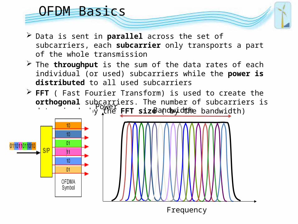
OFDM Basics
Data is sent in parallel across the set of subcarriers, each subcarrier only transports a part of the whole transmission
The throughput is the sum of the data rates of each individual (or used) subcarriers while the power is distributed to all used subcarriers
FFT ( Fast Fourier Transform) is used to create the orthogonal subcarriers. The number of subcarriers is determined by the FFT size ( by the bandwidth)
Power
Frequency
Bandwidth
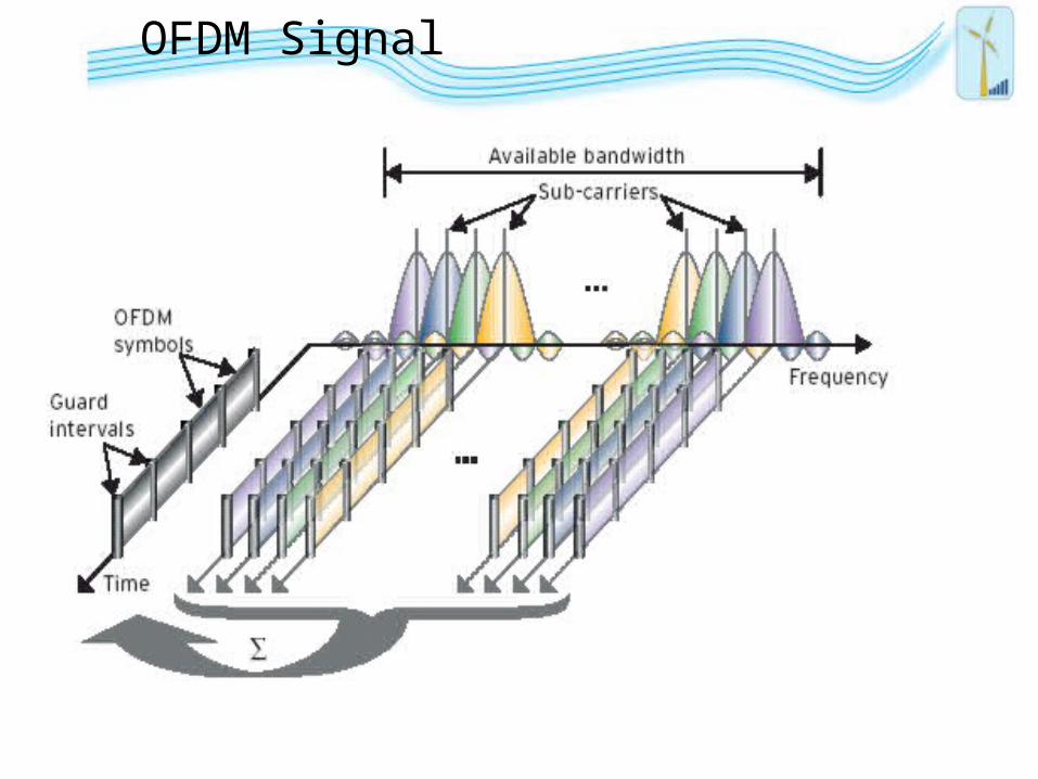
OFDM Signal
DeekshaTech
www.deekshatech.in
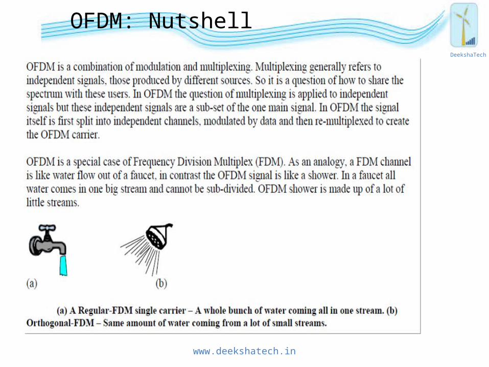
OFDM: Nutshell

Frequency-Time Representation
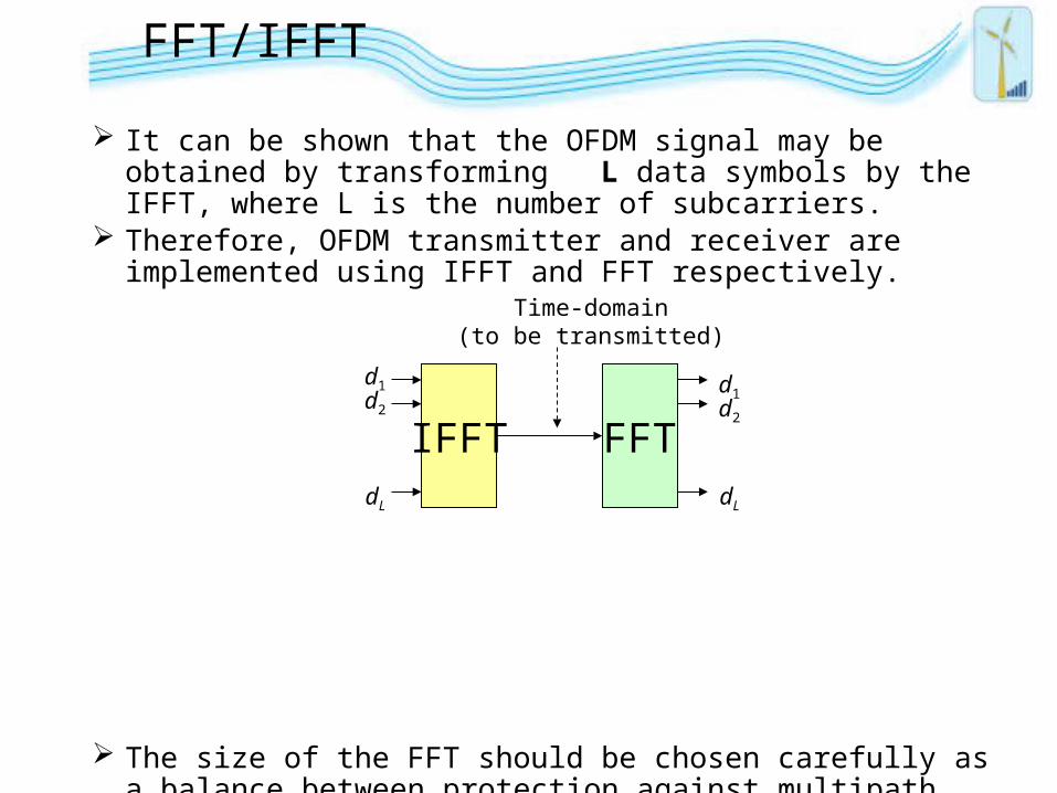
FFT/IFFT
It can be shown that the OFDM signal may be obtained by transforming L data symbols by the IFFT, where L is the number of subcarriers.
Therefore, OFDM transmitter and receiver are implemented using IFFT and FFT respectively.
The size of the FFT should be chosen carefully as a balance between protection against multipath (i.e. ISI), temporal variations (i.e. ICI), and design cost/complexity.
LTE FFT period is 66.67 usec, corresponding to the 15 KHz subcarrier separation.
IFFT FFT
d1d2
dL
d1d2
dL
Time-domain(to be transmitted)
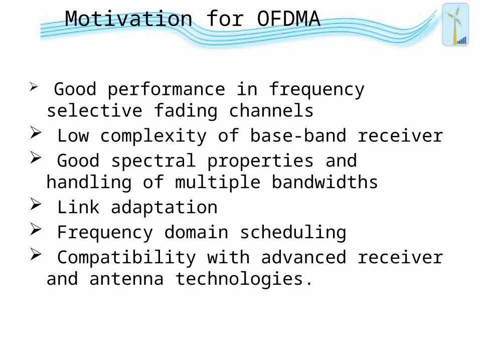
Motivation for OFDMA
Good performance in frequency selective fading channels
Low complexity of base-band receiver Good spectral properties and handling of multiple
bandwidths Link adaptation Frequency domain scheduling Compatibility with advanced receiver and antenna
technologies.

Challenges
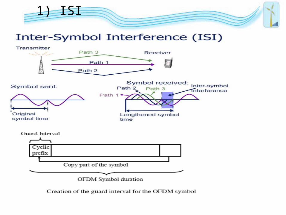
1) ISI
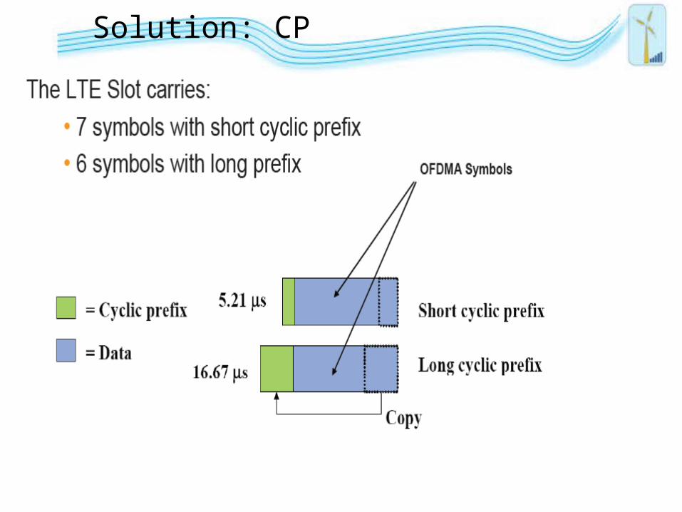
Solution: CP
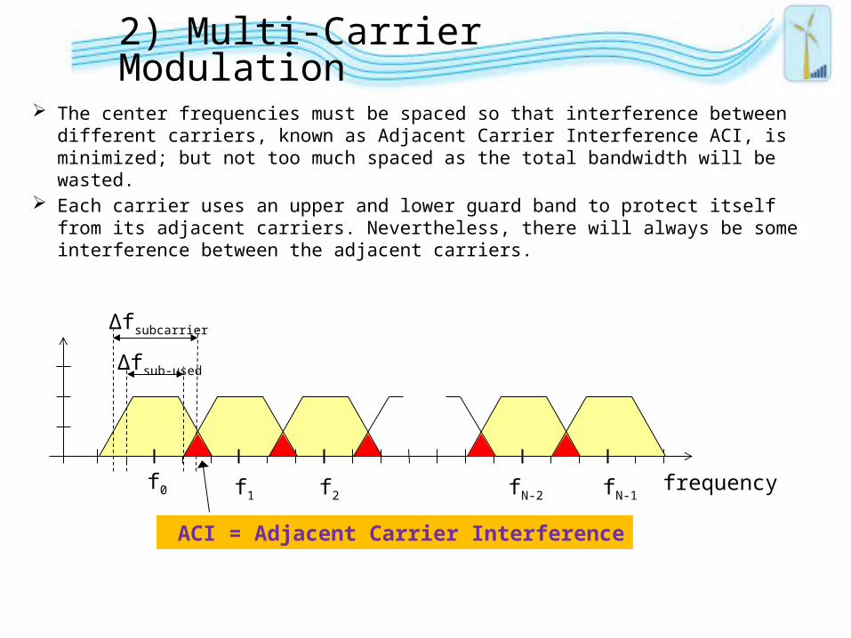
2) Multi-Carrier Modulation
The center frequencies must be spaced so that interference between different carriers, known as Adjacent Carrier Interference ACI, is minimized; but not too much spaced as the total bandwidth will be wasted.
Each carrier uses an upper and lower guard band to protect itself from its adjacent carriers. Nevertheless, there will always be some interference between the adjacent carriers.
frequency
∆fsubcarrier
f0 f1 f2 fN-1fN-2
∆fsub-used
ACI = Adjacent Carrier Interference
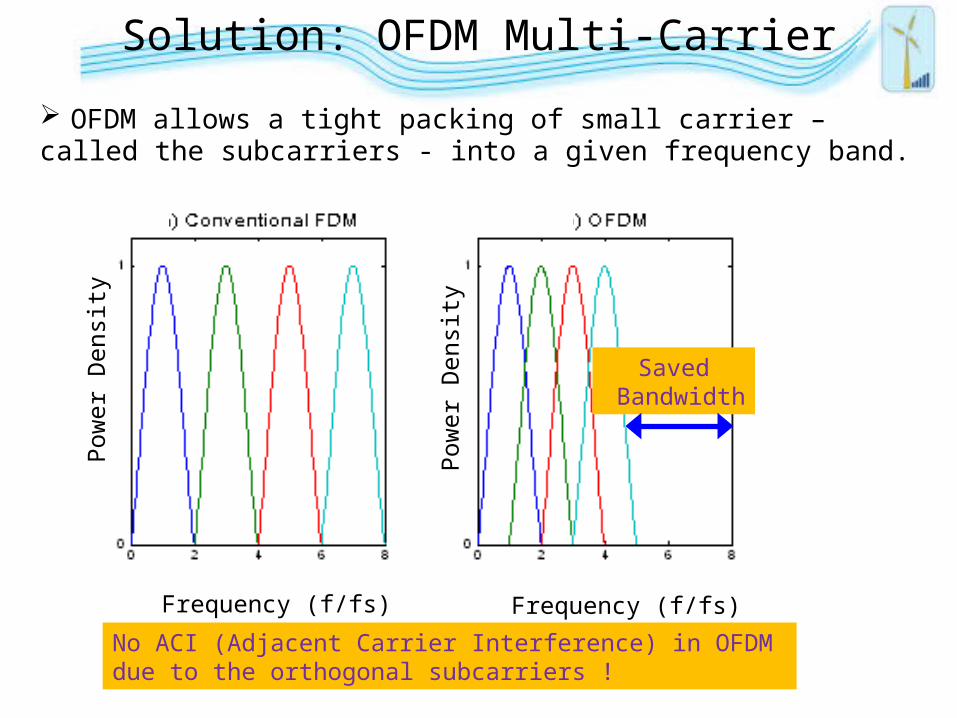
Solution: OFDM Multi-Carrier
OFDM allows a tight packing of small carrier – called the subcarriers - into a given frequency band.
No ACI (Adjacent Carrier Interference) in OFDM due to the orthogonal subcarriers !
Pow
er D
ensi
ty
Pow
er D
ensi
ty
Frequency (f/fs) Frequency (f/fs)
Saved Bandwidth
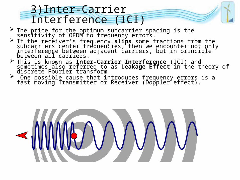
3)Inter-Carrier Interference (ICI)
The price for the optimum subcarrier spacing is the sensitivity of OFDM to frequency errors.
If the receiver’s frequency slips some fractions from the subcarriers center frequencies, then we encounter not only interference between adjacent carriers, but in principle between all carriers.
This is known as Inter-Carrier Interference (ICI) and sometimes also referred to as Leakage Effect in the theory of discrete Fourier transform.
One possible cause that introduces frequency errors is a fast moving Transmitter or Receiver (Doppler effect).
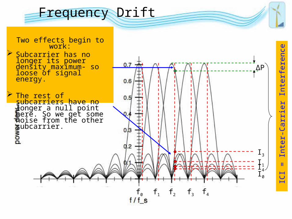
f0 f1 f2 f3 f4
∆P
I3
I1I4I0
ICI =
Inte
r-Ca
rrie
r Int
erfe
renc
e
Frequency Drift
Two effects begin to work: Subcarrier has no longer its
power density maximum- so loose of signal energy.
The rest of subcarriers have no longer a null point here. So we get some noise from the other subcarrier.
LowPassLowPass
cos(2πfct)
-sin(2πfct)
I
Q
ModulationMapper
ModulationMapper
IFFTIFFT
s0
ModulationMapper
ModulationMapper
s1
ModulationMapper
ModulationMapper
sN-1
b10 ,b11,…
Serial toParallel
Converter(Bit
Distrib.)
Serial toParallel
Converter(Bit
Distrib.)
b20 ,b21,…
bN-1 0 …
BinaryCodedData
.
.
.
D
A
D
Ax0, x1, …, xN-1 IQSplitIQ
Split
LowPassLowPass
D
A
D
A
RF
freq.f1 f2f0 fN-1
…
s0
s1 sN-1
s2
Freq
uenc
y D
omai
n
timet1 t2t0 tN-1 …x0 x1
xN-1
x2
TimeDomain
CP/G
uard
Gen
erati
onCP
/Gua
rdG
ener
ation
I
Q
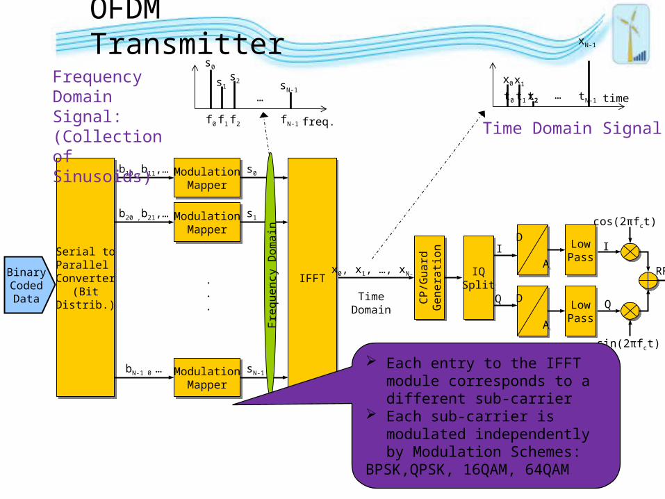
Time Domain Signal
Frequency Domain Signal:(Collection of Sinusoids)
Each entry to the IFFT module corresponds to a different sub-carrier
Each sub-carrier is modulated independently by Modulation Schemes:
BPSK,QPSK, 16QAM, 64QAM
OFDM Transmitter
reference(pilot)
Chan
nel C
orre
ction
Chan
nel C
orre
ction
Dem
odul
ator
Dem
odul
ator
Bit MappingBit Mapping
j
I
Q
A
D
A
D
ChannelEstimationChannel
Estimation
RF
Low
Noi
se A
mp.
+ Ba
ndpa
ssLo
w N
oise
Am
p.+
Band
pass
A
D
A
D
AGCAutomatic
Gain Control
AGCAutomatic
Gain Control
De-rotator
sign
al st
reng
th
LNA gain
Frequency And Timing SyncFrequency And Timing Sync
sign
al a
utoc
orre
ation
phas
e co
rrec
tion
timee
adju
st
.
.
.
s’0
s’1
s’N-1
chan
nel
resp
onse
s0
Bit MappingBit Mappings1
Bit MappingBit MappingsN-1
.
.
.
.
.
.
.
.
.
B10 ,B11,…
B20 ,B21,…
BN-1 0 …
Bit D
istrib
ution
Bit D
istrib
ution
Soft BitCodedData
freq.f1 f2f0 fN-1
…
s0s1 sN-1
s2
Frequency Domain
Time Domain
timet1 t2t0 tN-1
…y0 y1
yN-1
x2
QPSK
Im
Re
10
11
00
01
sk
d11
d10
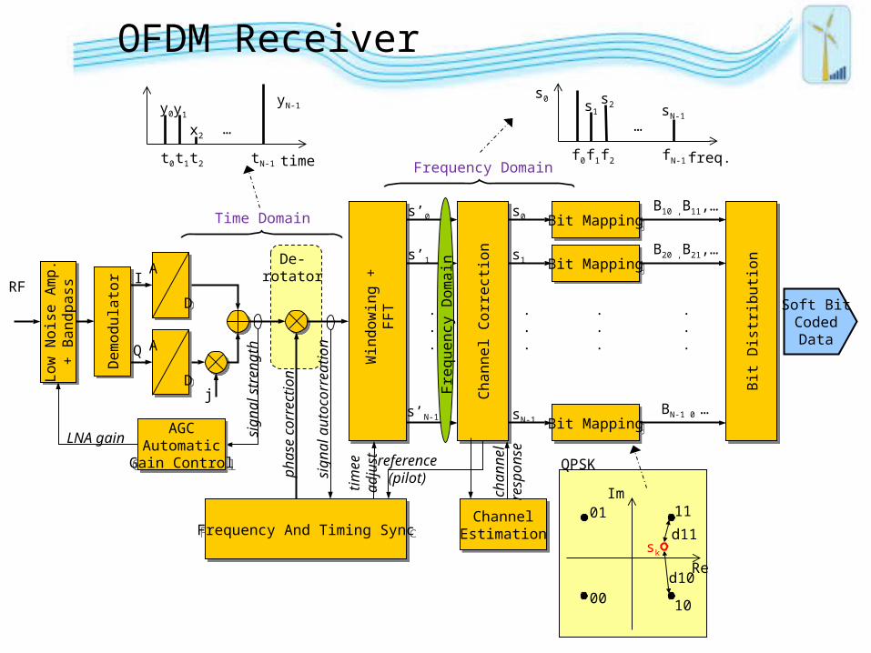
OFDM Receiver
Win
dow
ing
+FF
T
Freq
uenc
y D
omai
n
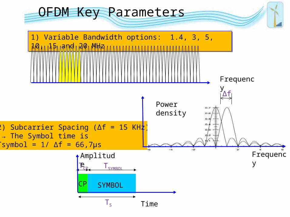
OFDM Key Parameters
2) Subcarrier Spacing (Δf = 15 KHz) → The Symbol time isTsymbol = 1/ Δf = 66,7μs
Δf
TSYMBOL
TCP SYMBOL
TCP
TS
Frequency
Time
Powerdensity
Amplitude
1) Variable Bandwidth options: 1.4, 3, 5, 10, 15 and 20 MHz1) Variable Bandwidth options: 1.4, 3, 5, 10, 15 and 20 MHz
Frequency
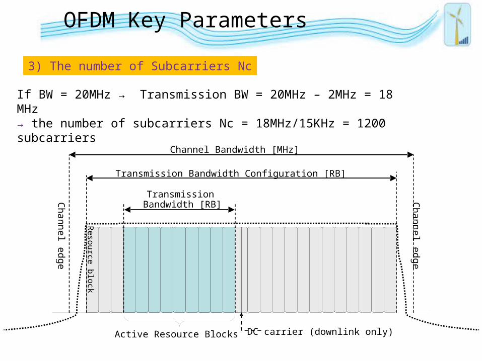
3) The number of Subcarriers Nc
If BW = 20MHz → Transmission BW = 20MHz – 2MHz = 18 MHz→ the number of subcarriers Nc = 18MHz/15KHz = 1200 subcarriers
TransmissionBandwidth [RB]
Transmission Bandwidth Configuration [RB]
Channel Bandwidth [MHz]
Resource block
Channel edge
Channel edge
DC carrier (downlink only)Active Resource Blocks
OFDM Key Parameters
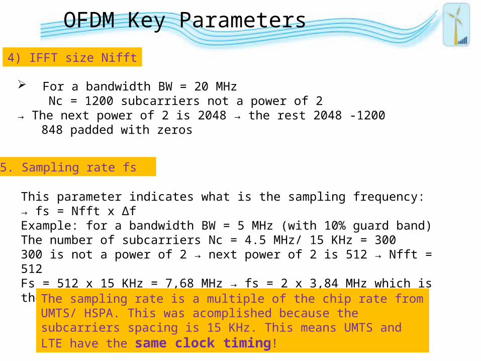
4) IFFT size Nifft
For a bandwidth BW = 20 MHz Nc = 1200 subcarriers not a power of 2
→ The next power of 2 is 2048 → the rest 2048 -1200 848 padded with zeros
5. Sampling rate fs
This parameter indicates what is the sampling frequency:→ fs = Nfft x ΔfExample: for a bandwidth BW = 5 MHz (with 10% guard band)The number of subcarriers Nc = 4.5 MHz/ 15 KHz = 300 300 is not a power of 2 → next power of 2 is 512 → Nfft = 512Fs = 512 x 15 KHz = 7,68 MHz → fs = 2 x 3,84 MHz which is the chip rate in UMTS!!
The sampling rate is a multiple of the chip rate from UMTS/ HSPA. This was acomplished because the subcarriers spacing is 15 KHz. This means UMTS and LTE have the same clock timing!
OFDM Key Parameters
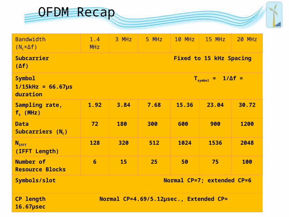
Bandwidth(NC×Δf)
1.4 MHz 3 MHz 5 MHz 10 MHz 15 MHz 20 MHz
Subcarrier Fixed to 15 kHz Spacing (Δf)
Symbol Tsymbol = 1/Δf = 1/15kHz = 66.67μsduration
Sampling rate, fS (MHz)
1.92 3.84 7.68 15.36 23.04 30.72
DataSubcarriers (NC)
72 180 300 600 900 1200
NIFFT (IFFT Length)
128 320 512 1024 1536 2048
Number of Resource Blocks
6 15 25 50 75 100
Symbols/slot Normal CP=7; extended CP=6
CP length Normal CP=4.69/5.12μsec., Extended CP= 16.67μsec
OFDM Recap
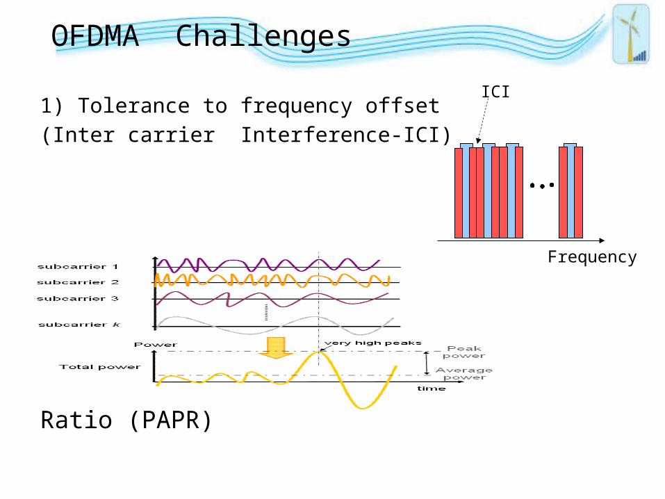
OFDMA Challenges
1) Tolerance to frequency offset
(Inter carrier Interference-ICI)
2) High Peak-to-Average Power Ratio (PAPR)
Frequency
ICI
SC FDMA
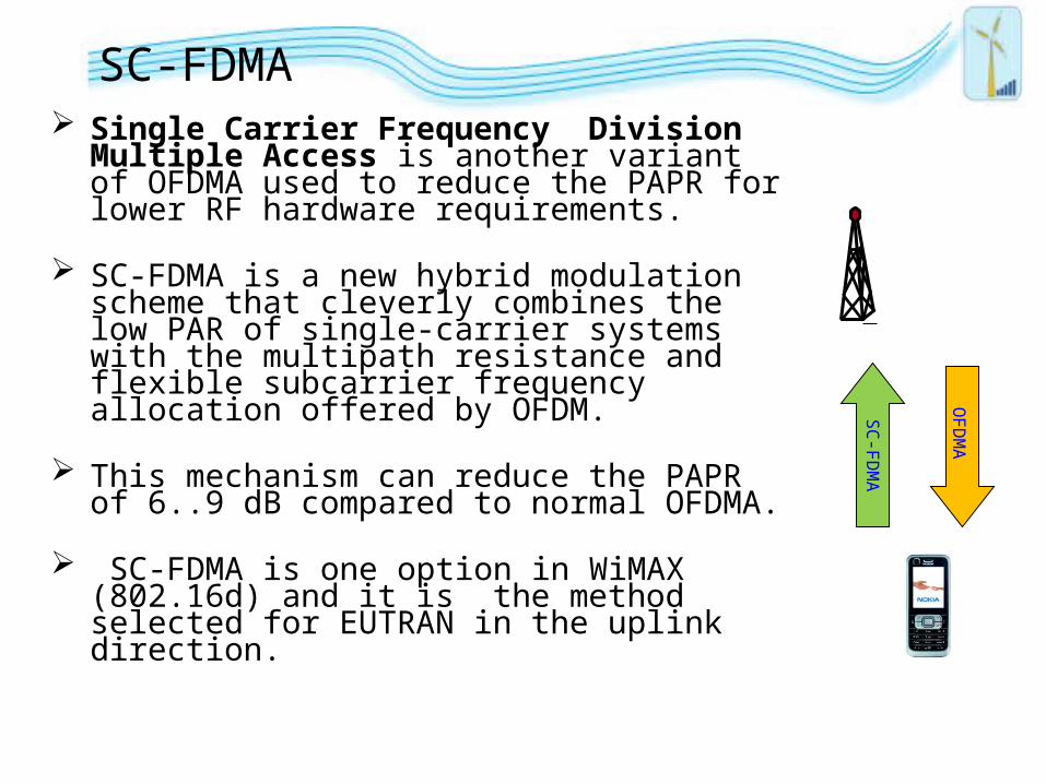
SC-FDMA Single Carrier Frequency Division Multiple
Access is another variant of OFDMA used to reduce the PAPR for lower RF hardware requirements.
SC-FDMA is a new hybrid modulation scheme that cleverly combines the low PAR of single-carrier systems with the multipath resistance and flexible subcarrier frequency allocation offered by OFDM.
This mechanism can reduce the PAPR of 6..9 dB compared to normal OFDMA.
SC-FDMA is one option in WiMAX (802.16d) and it is the method selected for EUTRAN in the uplink direction.
SC-FDM
A
OFD
MA
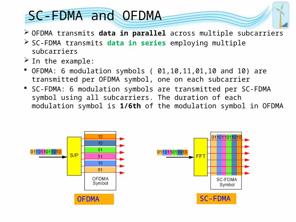
SC-FDMA and OFDMA OFDMA transmits data in parallel across multiple subcarriers SC-FDMA transmits data in series employing multiple subcarriers In the example: OFDMA: 6 modulation symbols ( 01,10,11,01,10 and 10) are
transmitted per OFDMA symbol, one on each subcarrier SC-FDMA: 6 modulation symbols are transmitted per SC-FDMA
symbol using all subcarriers. The duration of each modulation symbol is 1/6th of the modulation symbol in OFDMA
OFDMA SC-FDMA
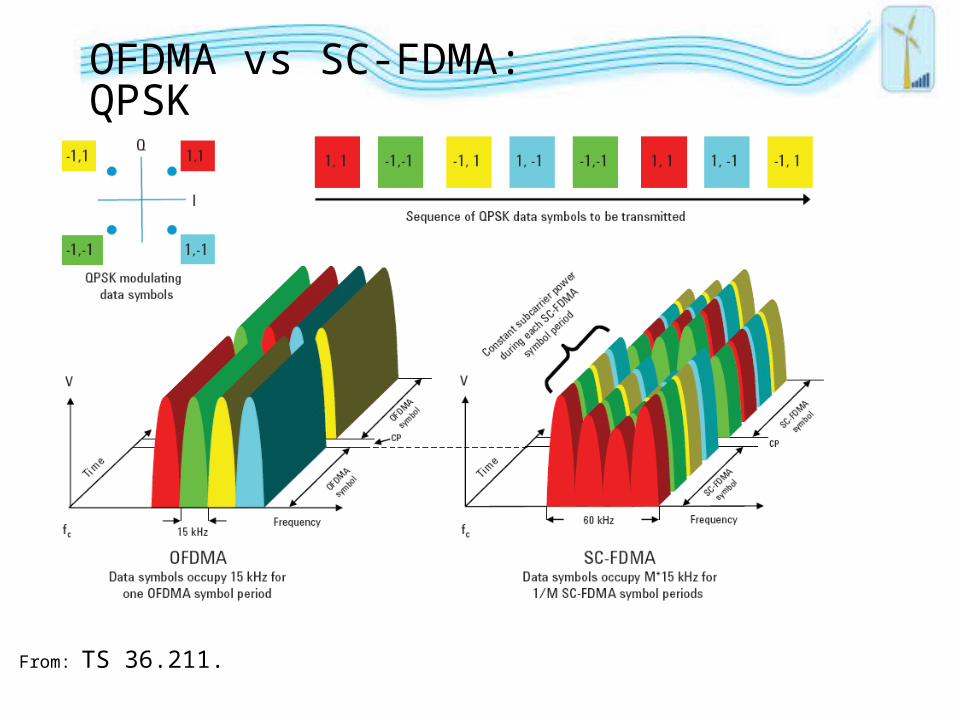
OFDMA vs SC-FDMA: QPSK
From: TS 36.211.
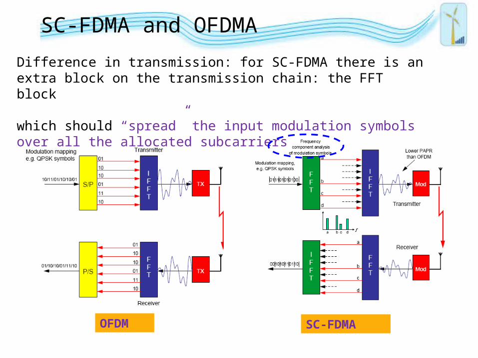
OFDM SC-FDMA
Difference in transmission: for SC-FDMA there is an extra block on the transmission chain: the FFT block
which should “spread” the input modulation symbols over all the allocated subcarriers
SC-FDMA and OFDMA
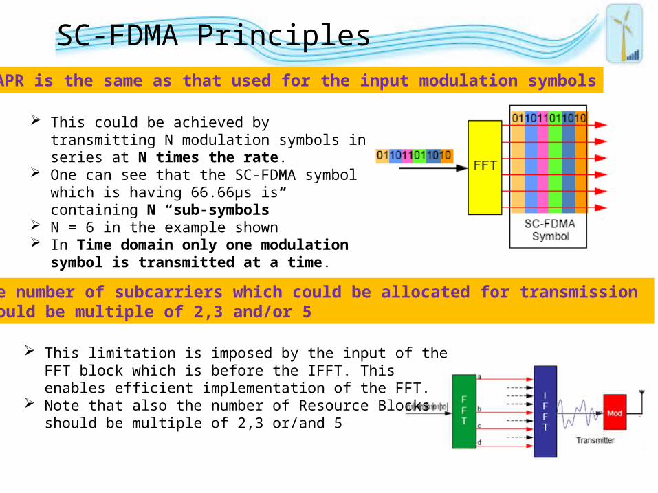
SC-FDMA Principles PAPR is the same as that used for the input modulation symbols
This could be achieved by transmitting N modulation symbols in series at N times the rate.
One can see that the SC-FDMA symbol which is having 66.66µs is containing N “sub-symbols”
N = 6 in the example shown In Time domain only one modulation symbol
is transmitted at a time.
The number of subcarriers which could be allocated for transmission should be multiple of 2,3 and/or 5
This limitation is imposed by the input of the FFT block which is before the IFFT. This enables efficient implementation of the FFT.
Note that also the number of Resource Blocks should be multiple of 2,3 or/and 5
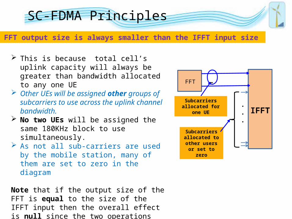
The FFT output size is always smaller than the IFFT input size
FFT
IFFT
…
.
.
.
Subcarriers allocated for one
UE
Subcarriers allocated to
other users or set to zero
This is because total cell’s uplink capacity will always be greater than bandwidth allocated to any one UE
Other UEs will be assigned other groups of subcarriers to use across the uplink channel bandwidth.
No two UEs will be assigned the same 180KHz block to use simultaneously.
As not all sub-carriers are used by the mobile station, many of them are set to zero in the diagram
Note that if the output size of the FFT is equal to the size of the IFFT input then the overall effect is null since the two operations (FFT and IFFT are complementary)
SC-FDMA Principles
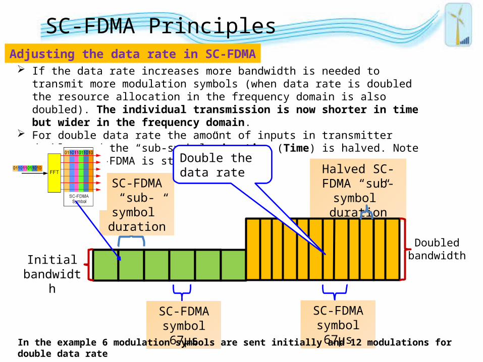
Adjusting the data rate in SC-FDMA
Halved SC-FDMA “sub-symbol”
duration
Initial bandwidth
SC-FDMA “sub-
symbol” duration
Doubled bandwidth
If the data rate increases more bandwidth is needed to transmit more modulation symbols (when data rate is doubled the resource allocation in the frequency domain is also doubled). The individual transmission is now shorter in time but wider in the frequency domain.
For double data rate the amount of inputs in transmitter doubles and the “sub-symbol” duration (Time) is halved. Note that the SC-FDMA is still 67 µs
Double the data rate
SC-FDMA symbol 67µs
SC-FDMA symbol 67µs
SC-FDMA Principles
In the example 6 modulation symbols are sent initially and 12 modulations for double data rate
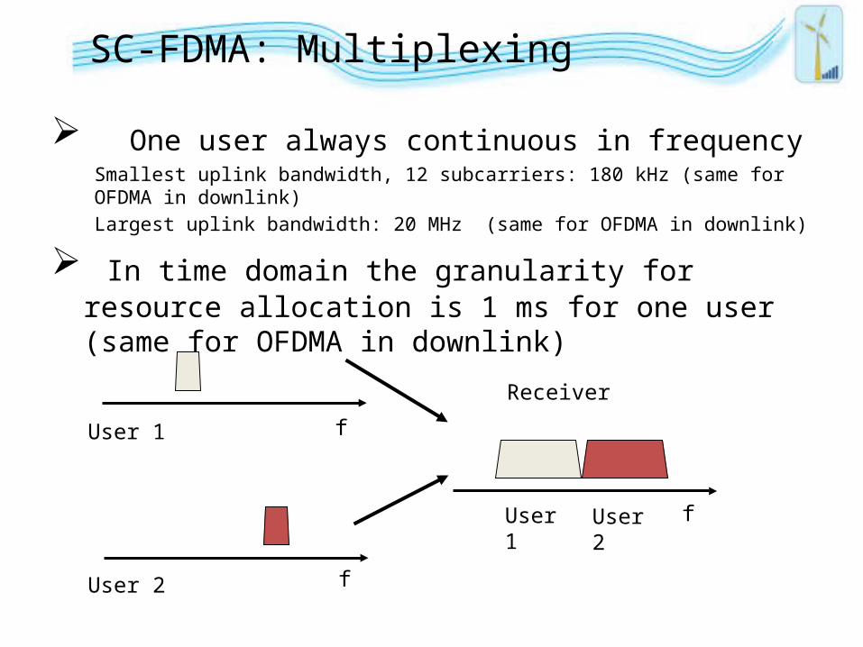
SC-FDMA: Multiplexing
One user always continuous in frequencySmallest uplink bandwidth, 12 subcarriers: 180 kHz (same for OFDMA in downlink)
Largest uplink bandwidth: 20 MHz (same for OFDMA in downlink)
In time domain the granularity for resource allocation is 1 ms for one user (same for OFDMA in downlink)
User 2 f
User 1 f
f
Receiver
User 1 User 2
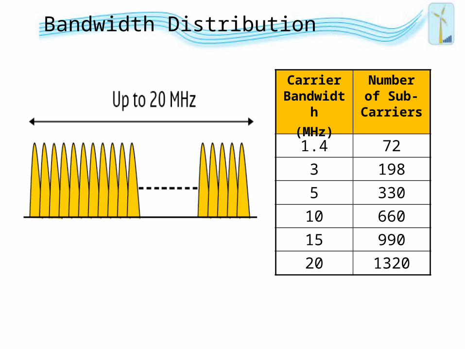
Bandwidth Distribution
Carrier Bandwidth
(MHz)
Number of Sub-
Carriers
1.4 72
3 198
5 330
10 660
15 990
20 1320
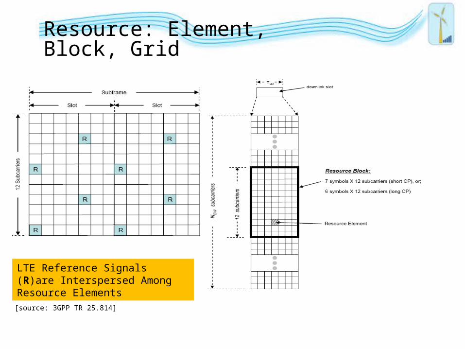
Resource: Element, Block, Grid
[source: 3GPP TR 25.814]
LTE Reference Signals (R)are Interspersed Among Resource Elements
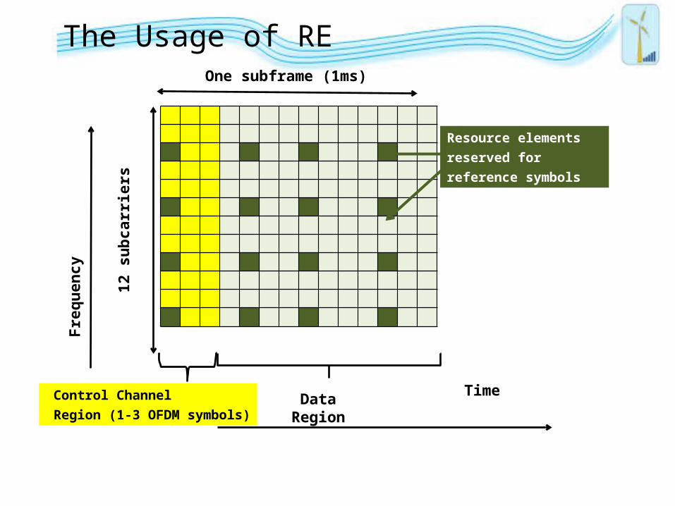
The Usage of RE
Resource elements
reserved for
reference symbols
Control Channel
Region (1-3 OFDM symbols)
One subframe (1ms)
12 s
ub
carr
iers
Fre
qu
ency
Time Data Region
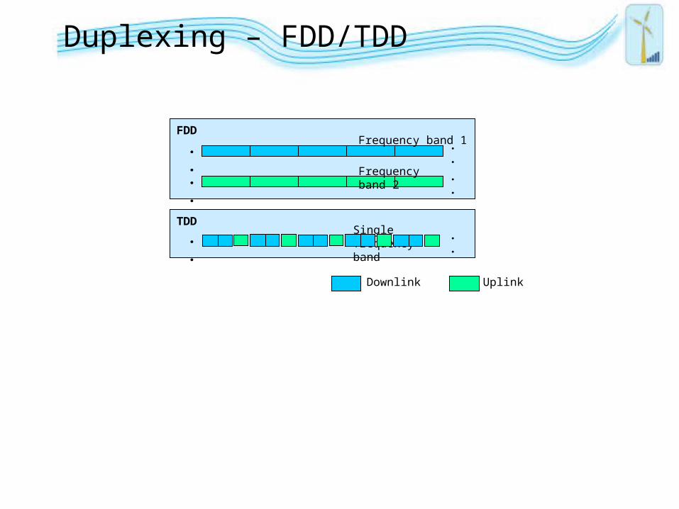
Duplexing – FDD/TDD
FDD
..
..
..
..
Downlink Uplink
Frequency band 1
Frequency band 2
.. ..Single frequency band
TDD
.
.
.
.
.
.
.
.
.
.
.
.
.
.
.
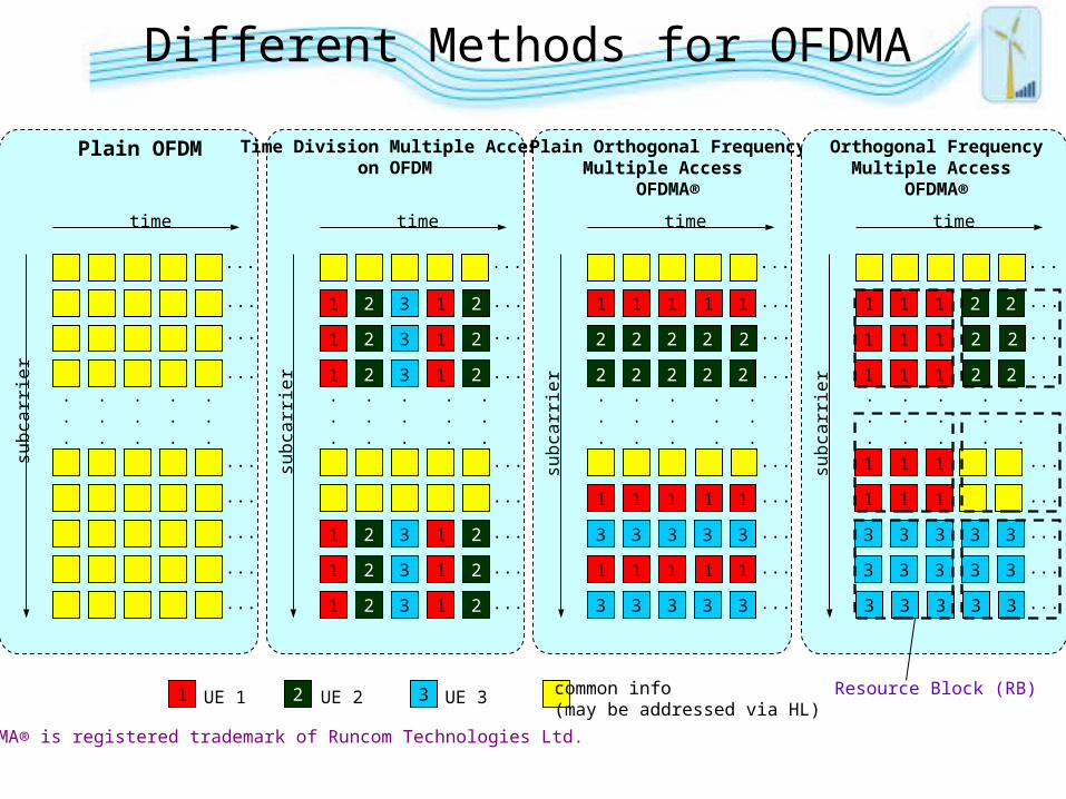
Plain OFDM
time
subc
arrie
r
...
...
...
...
...
...
...
...
...
1
1
1
1
1
1
.
.
.
2
2
2
2
2
2
.
.
.
3
3
3
3
3
3
.
.
.
.
.
.
.
.
.
Time Division Multiple Accesson OFDM
time
subc
arrie
r...
...
...
...
...
...
...
...
...
1
1
1
1
1
1
2
2
2
2
2
2
OFDMA® is registered trademark of Runcom Technologies Ltd.
1 1 1
1
.
.
.
2
2 2
2...
3 33 3 3
.
.
.
.
.
.
.
.
.
Plain Orthogonal FrequencyMultiple Access
OFDMA®
time
...
...
...
...
...
...
...
...
...
1 1
1 1 1 1
2 22
2 2 2
1
3 33 3 3
1 1 1 1su
bcar
rier
1
1
1
.
.
.
2
.
.
.
3
.
.
.
.
.
.
.
.
.
Orthogonal FrequencyMultiple Access
OFDMA®
time
...
...
...
...
...
...
...
...
...
1
1
1 1
2
22
2 2
3 33 3 3
1
subc
arrie
r
1
1 1 1
111
3 3 3
33 3 3 3
3
Resource Block (RB)1 2 3 common info(may be addressed via HL)
UE 1 UE 2 UE 3
Different Methods for OFDMA

“Thank you”