Embed Size (px)
Citation preview

MODULE 5MODULE 5
DATA FLOW DIAGRAMS
5.1 Developing Data Flow Diagrams(DFD) a) What are DFDs? b) Symbols used in DFD c) Rules of data flow d) Good style in drawing DFD5.2 Describing systems with DFD & Levelling DFDs5.3 Logical & Physical DFDs
System Analysis And Design System Analysis And Design © © V. Rajaraman
Learning Units

LEARNING GOALS
1 of 26
In this module we will learn1. What are Data Flow Diagrams (DFDs)?2. Why they are useful?3. How are they developed?4. How to level DFDs?5. Good style conventions in developing DFDs6. Difference between Logical and Physical DFDs7. Tools available to draw DFDs
Systems Analysis And Design Systems Analysis And Design © © V. Rajaraman
MOTIVATION
2 of 26
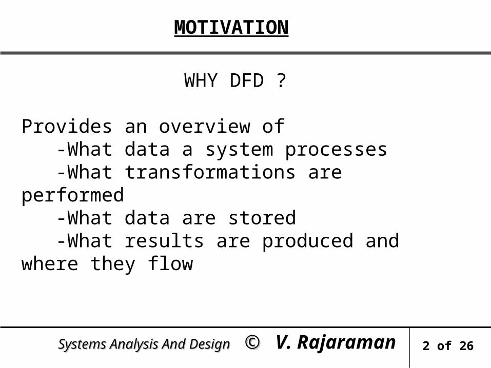
WHY DFD ?
Provides an overview of -What data a system processes -What transformations are performed -What data are stored -What results are produced and where they flow
Systems Analysis And Design Systems Analysis And Design © © V. Rajaraman

MOTIVATION
WHY DFD ?
Graphical nature makes it a good communication tool between -User and analyst -Analyst and System designer Structure of DFD allows starting from a broad overview and expand it to a hierarchy of detailed diagrams
Systems Analysis And Design Systems Analysis And Design © © V. Rajaraman
3 of 26

DATA FLOW DIAGRAMS
4 of 26
WHAT ARE DATA FLOW DIAGRAMS? DFDs models the system by depicting
External entities from which the data flows and where results terminate
Processes which transform data flows
Data stores from which the data are read or into
which data are written by the processes.
5.1.1 Systems Analysis And Design Systems Analysis And Design © © V. Rajaraman

SYMBOLS USED IN DFD
1.STORES
Stores demand note
Delivery slip
Issue Advice
PROCESS
A circle represents a process Straight lines with incoming arrows are input data flows Straight lines with outgoing arrows are output data flows Processes are given serial numbers for easy reference Labels are assigned to Data flow.These aid documentation
5.1.2 Systems Analysis And Design Systems Analysis And Design © © V. Rajaraman
5 of 26

SYMBOLS USED IN DFD
EXTERNAL ENTITIES
VENDOR CustomerInvoiceOrder
Bill
A Rectangle represents an external entity They either supply data or receive data They do not process data
5.1.3 Systems Analysis And Design Systems Analysis And Design © © V. Rajaraman
6 of 26

SYMBOLS USED IN DFD
DATA STORES
Inventory Writing Reading
A Data Store is a repository of data Data can be written into the data store
This is depicted by an outgoing arrow
Data can be read from a data storeThis is depicted by an incoming arrow
External entity cannot read or write to the data store Two data stores cannot be connected by a data flow
5.1.4 Systems Analysis And Design Systems Analysis And Design © © V. Rajaraman
7 of 26

RULES OF DATA FLOW
• Data can flow from -external entity to process -process to external entity -process to store and back -process to process
• Data cannot flow from -external entity to external entity -external entity to store -store to external entity -store to store
5.1.5 Systems Analysis And Design Systems Analysis And Design © © V. Rajaraman
8 of 26

DATA FLOW DIAGRAMS
An alternate notation is often used
3StoreIssue
Label
NameA Process
Name
Label
DS1 InventoryA Data store
5.1.6 Systems Analysis And Design Systems Analysis And Design © © V. Rajaraman
9 of 26

GOOD STYLE IN DRAWING DFD
Use meaningful names for data flows, processes and data stores.
Use top down development starting from context diagram and successively levelling DFD
Only previously stored data can be read
A process can only transfer input to output.It cannot create new data
Data stores cannot create new data
5.1.7 Systems Analysis And Design Systems Analysis And Design © © V. Rajaraman
10 of 26

DESCRIBING A SYSTEM WITH A DFD
An entire system is represented by one DFD which gives the system’s overview It is called a context diagram It gives little detail & is also known as the top level DFD
Context diagram of mess management is shown in the next transparency
5.2.1 Systems Analysis And Design Systems Analysis And Design © © V. Rajaraman
11 of 26

CONTEXT DIAGRAM OF MESS MANAGEMENT SYSTEM
MessManagement
System
Students
Mess manager Chief warden
Mess secretary
VendorsRequisitions
Payments
Daily rate
Menu
Overdue Payments
Item neededEach day
PerishableItems
Bills
Payments
Extras Note
Supplies
Overdue Bills
• Observe this diagram gives very little detail
5.2.2 Systems Analysis And Design Systems Analysis And Design © © V. Rajaraman
12 of 26

LEVELLING DFD
A context diagram gives an overview
It should be split into major processes which give greater detail.
Each major process is further split to give more detail.
Each major process is further split to give more detail
5.2.3 Systems Analysis And Design Systems Analysis And Design © © V. Rajaraman
13 of 26

WHY LEVEL DFD?
If a DFD is too detailed it will have too many data flows and will be large and difficult to understand
Start from a broad overview. Expand to details - Idea similar to using procedures and linking these with a main program
Each DFD must deal with one aspect of a big system
5.2.4 Systems Analysis And Design Systems Analysis And Design © © V. Rajaraman
14 of 26

EXPANDED DFD FOR HOSTEL MESS MANAGEMENT
Unpaid bills
1 Billing system
StudentsMess
Secretary Chief Warden
Mess manager
Payments Update dailyrate
Itemized bills at end of month
Extras/Rebates
Expenses
No of meals(today +3)
Items used each day
Student billingInformation + bills
• Going to next process (Continued in next slide)
5.2.5 Systems Analysis And Design Systems Analysis And Design © © V. Rajaraman
15 of 26

EXPANDED DFD FOR HOSTEL MESS MANAGEMENT
•Continued
5.2.6 Systems Analysis And Design Systems Analysis And Design © © V. Rajaraman
16 of 26
3Perishableordering
2Stores issue
and Control system
Mess Secretary
Mess Manager
Vendors
Orders(perishable)
Vendor data(perishable)
Vegetables and perishable requisition
Vendor data Stores inventory
Order data
Items usedtoday
Items to be issued(today +2)Vendor supplies
Order non-perishable
Menu(today +2)
Perishable order
Low stock (today+2)

EXPANDED DFD-BILLING SYSTEM
1.4Find no
Of meals to cook
1.1CalculateDaily rate
1.2CalculateStudent’s
bills1.3
Reconcilepayments
Chiefwarden
Mess Manager
Mess Secretary
Payments
Unpaid bills
Students data
Daily rate average(upto date)
Expenses data
Items rate dataStudents data
No of meals(today + 2)
Students data
Itemized bills
Bills
Extras/Rebates
• Observe numbering of processes5.2.7 Systems Analysis And Design Systems Analysis And Design © © V.
Rajaraman17 of 26

LEVELLING RULES
If process p is expanded, the process at the next level are labeled as p.1,p.2 etc.
All data flow entering or leaving p must also enter or leave its expanded version. Expanded DFD may have data stores No external entity can appear in expanded DFD Keep the number of processes at each level less than 7.
5.2.8 Systems Analysis And Design Systems Analysis And Design © © V. Rajaraman
18 of 26

ILLEGAL CONSTRUCTS IN DFD
No loops are allowed in DFD A process cannot be a pure decision
A single data flow should not be split into many flows with different labels
No data flow allowed between data stores
Compare
Actual rate > Standard rate
Actual rate <= Standard rate
Actual daily rate
Standard daily rate
5.2.9 Systems Analysis And Design Systems Analysis And Design © © V. Rajaraman
19 of 26

ILLEGAL CONSTRUCTS IN DFD
Get studentsextra/rebates
record
Calculate Bill
Extra/rebate store
Record
Ask for next record
• Not correct as loop is formed
5.2.10 Systems Analysis And Design Systems Analysis And Design © © V. Rajaraman
20 of 26

Order for items
LEVELLING EXAMPLES
5.2.11 Systems Analysis And Design Systems Analysis And Design © © V. Rajaraman
21 of 26
2Stores issue
and control system
Mess secretary
Vendor
Mess manager
Menu for(Today +2)
Vendor supplies
Vendor
Low message stock
Items issued
Items to be used on (today +2)
Low stock item (today +2) No of meals to
be cooked (today +2)
Stores inventory
Order
Stores issue control system process

LEVELLING EXAMPLES
5.2.11 Systems Analysis And Design Systems Analysis And Design © © V. Rajaraman
22 of 26
2.1Inventory update
And low stock warning
2.2Create orderfor vendor
2.4Check Itemavailability
2.3Calculate Items
needed
Mess manager
Mess secretary
Vendor
Items used today
Low stockitem
Stores inventory Order Vendor data
Items neededFrom 2.3
Vendor supplies
Order to vendor
Menu(today +2)
Items needed Low stock items (today+2)
No of meals to (today +2)
Stores inventory

LEVELLING EXAMPLES
5.2.12 Systems Analysis And Design Systems Analysis And Design © © V. Rajaraman
23 of 26
TopLevel process
Ext BExt A
1 2 4
3
Ext BExt A
F1 F4
1.1 1.2 1.4
1.3
2.1 2.2 2.3
F1
Ext A
Ext B 4.3 4.1 4.23.1 3.2 3.4
3.3
F4
Process 1 Process 2

LOGICAL AND PHYSICAL DFD
DFD’S considered so far are called logical DFDs
A physical DFD is similar to a document flow diagram. It specifies who does the operations specified by the logical DFD
Physical DFD may depict physical movements of the goods
Physical DFDs can be drawn during fact gathering phase of a life cycle
5.3.1 Systems Analysis And Design Systems Analysis And Design © © V. Rajaraman
24 of 26

PHYSICAL DFD FOR ENCASHING CHEQUE
5.3.2 Systems Analysis And Design Systems Analysis And Design © © V. Rajaraman
25 of 26
Customer
ClerkVerify A/CSignatureUpdateBalance
CashierVerify Token
Take Signature
Cash
Cheque Cheque withToken number
Bad Cheque
Customer Accounts
Store cheques Entry inDay Book
Token
Token

LOGICAL DFD FOR CHEQUE ENCASHMENT
RetrieveCustomerRecord
CheckBalance,
Issuetoken
StoreToken no& cheques
Search& match
token
UpdateDaily
cash bookCustomer
Day bookCash
Token Slip
Cheque with token
ChequeCheque with Token
Cheque Customer accounts
Cheque storeWith token no.
Token SlipOr cheque
5.3.3 Systems Analysis And Design Systems Analysis And Design © © V. Rajaraman
26 of 26