Embed Size (px)
DESCRIPTION
Â
Citation preview
1
DIGITAL DESIGN + FABRICATION SM1, 2015 Module 4
Chung-Liang Anthony Lee (694830) Rosie Gunzburg
Thursday 1pm-3pm
2
3
4
5
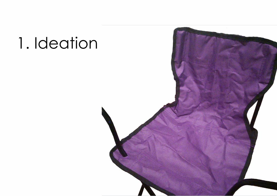
1. Ideation
6
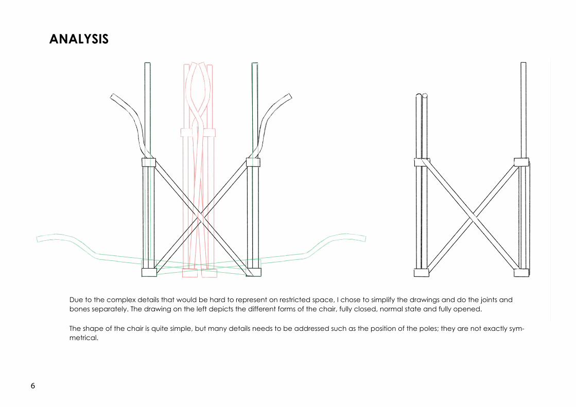
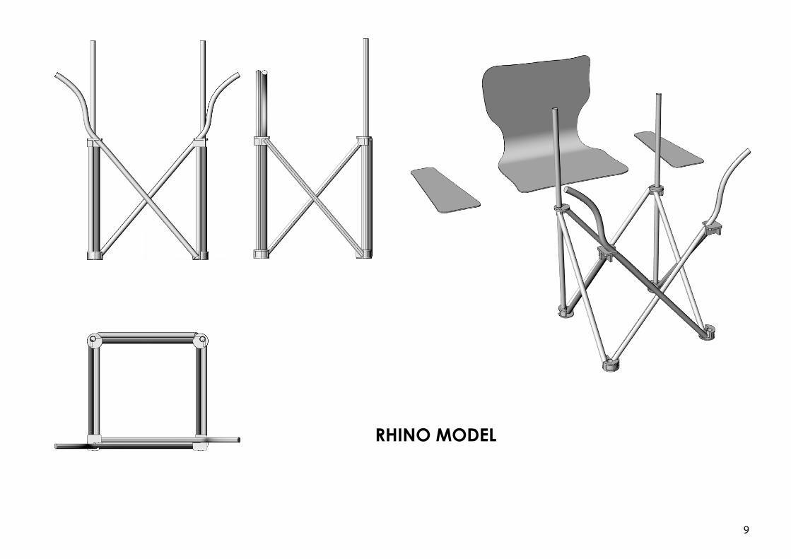
Due to the complex details that would be hard to represent on restricted space, I chose to simplify the drawings and do the joints and bones separately. The drawing on the left depicts the different forms of the chair, fully closed, normal state and fully opened.
The shape of the chair is quite simple, but many details needs to be addressed such as the position of the poles; they are not exactly sym-metrical.
ANALYSIS
7
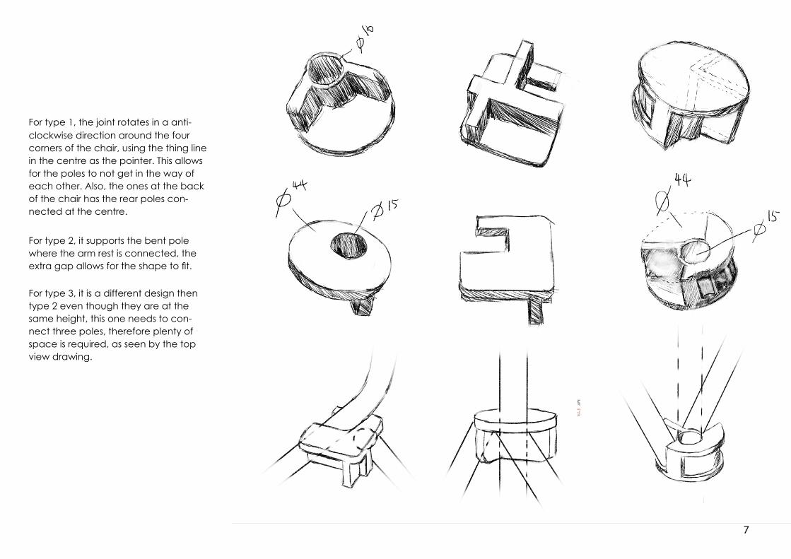
For type 1, the joint rotates in a anti-clockwise direction around the four corners of the chair, using the thing line in the centre as the pointer. This allows for the poles to not get in the way of each other. Also, the ones at the back of the chair has the rear poles con-nected at the centre.
For type 2, it supports the bent pole where the arm rest is connected, the extra gap allows for the shape to fit.
For type 3, it is a different design then type 2 even though they are at the same height, this one needs to con-nect three poles, therefore plenty of space is required, as seen by the top view drawing.
8
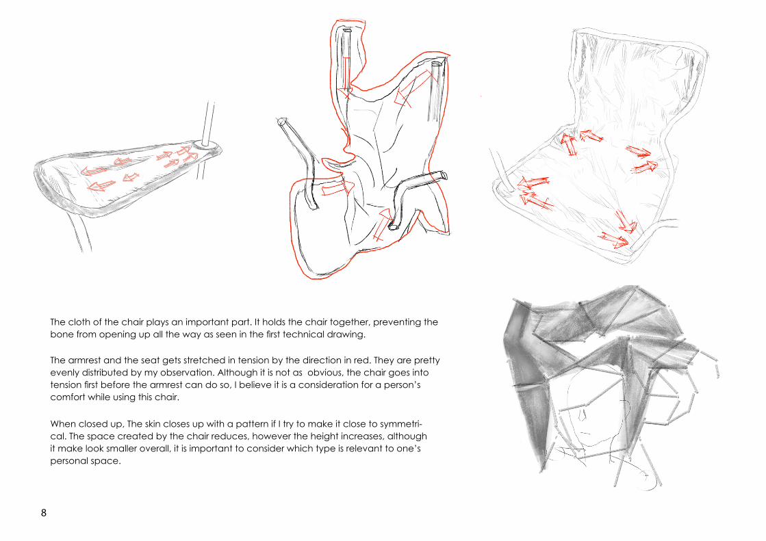
The cloth of the chair plays an important part. It holds the chair together, preventing the bone from opening up all the way as seen in the first technical drawing.
The armrest and the seat gets stretched in tension by the direction in red. They are pretty evenly distributed by my observation. Although it is not as obvious, the chair goes into tension first before the armrest can do so, I believe it is a consideration for a person’s comfort while using this chair.
When closed up, The skin closes up with a pattern if I try to make it close to symmetri-cal. The space created by the chair reduces, however the height increases, although it make look smaller overall, it is important to consider which type is relevant to one’s personal space.
9
RHINO MODEL

10
RECONFIGURED MODEL
11
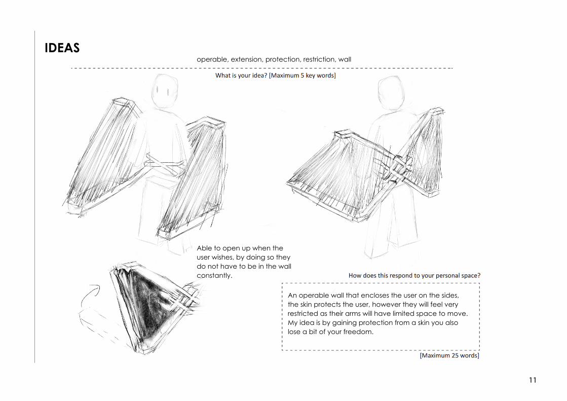
operable, extension, protection, restriction, wall
An operable wall that encloses the user on the sides, the skin protects the user, however they will feel very restricted as their arms will have limited space to move. My idea is by gaining protection from a skin you also lose a bit of your freedom.
Able to open up when the user wishes, by doing so they do not have to be in the wall constantly.
IDEAS
12
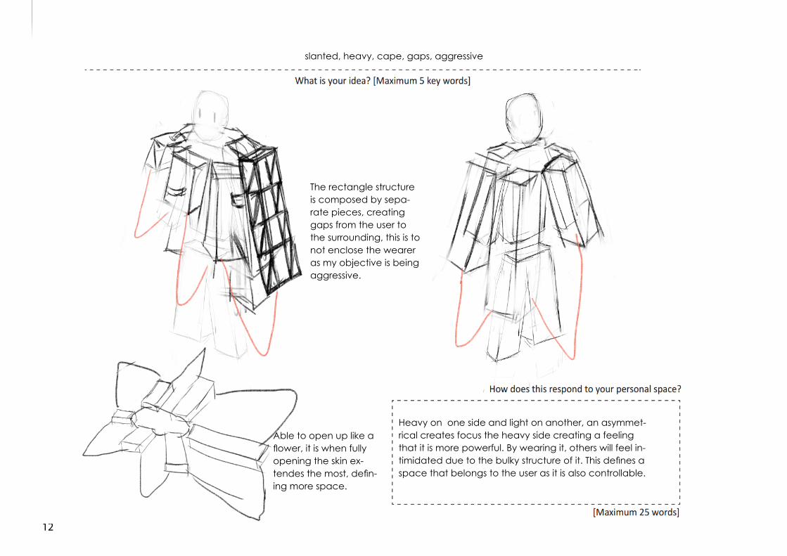
Heavy on one side and light on another, an asymmet-rical creates focus the heavy side creating a feeling that it is more powerful. By wearing it, others will feel in-timidated due to the bulky structure of it. This defines a space that belongs to the user as it is also controllable.
slanted, heavy, cape, gaps, aggressive
Able to open up like a flower, it is when fully opening the skin ex-tendes the most, defin-ing more space.
The rectangle structure is composed by sepa-rate pieces, creating gaps from the user to the surrounding, this is to not enclose the wearer as my objective is being aggressive.
13
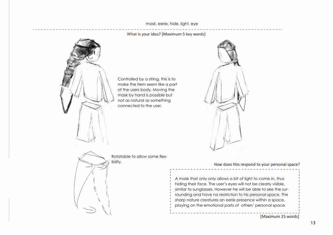
mask, eerie, hide, light, eye
A mask that only only allows a bit of light to come in, thus hiding their face. The user’s eyes will not be clearly visible, similar to sunglasses. However he will be able to see the sur-rounding and have no restriction to his personal space. The sharp nature creatures an eerie presence within a space, playing on the emotional parts of others’ personal space.
Rotatable to allow some flex-ibility.
Controlled by a string, this is to make the item seem like a part of the users body. Moving the mask by hand is possible but not as natural as something connected to the user.
14
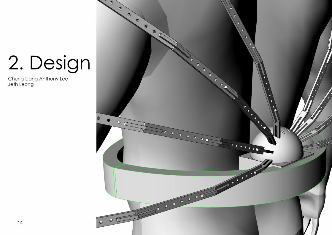
2. DesignChung-Liang Anthony LeeJeth Leong
15
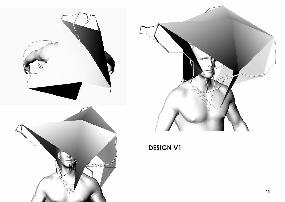
DESIGN V1
16
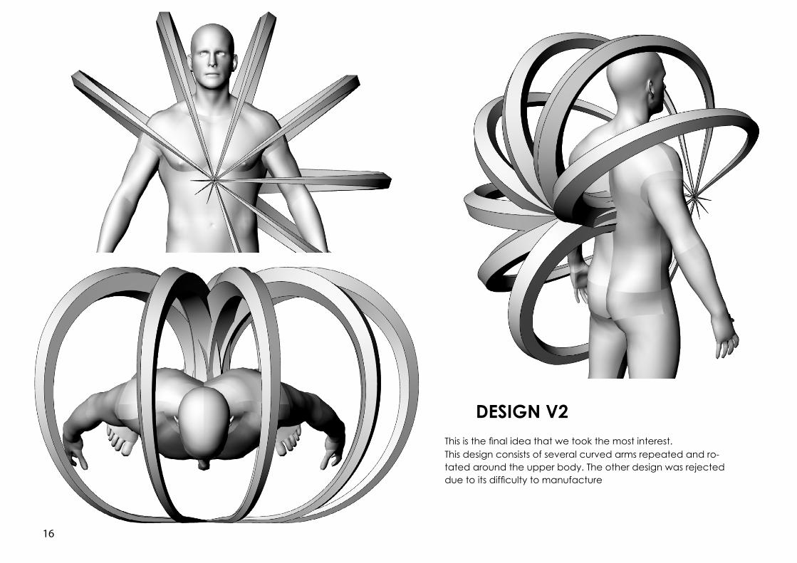
DESIGN V2This is the final idea that we took the most interest.This design consists of several curved arms repeated and ro-tated around the upper body. The other design was rejected due to its difficulty to manufacture
17
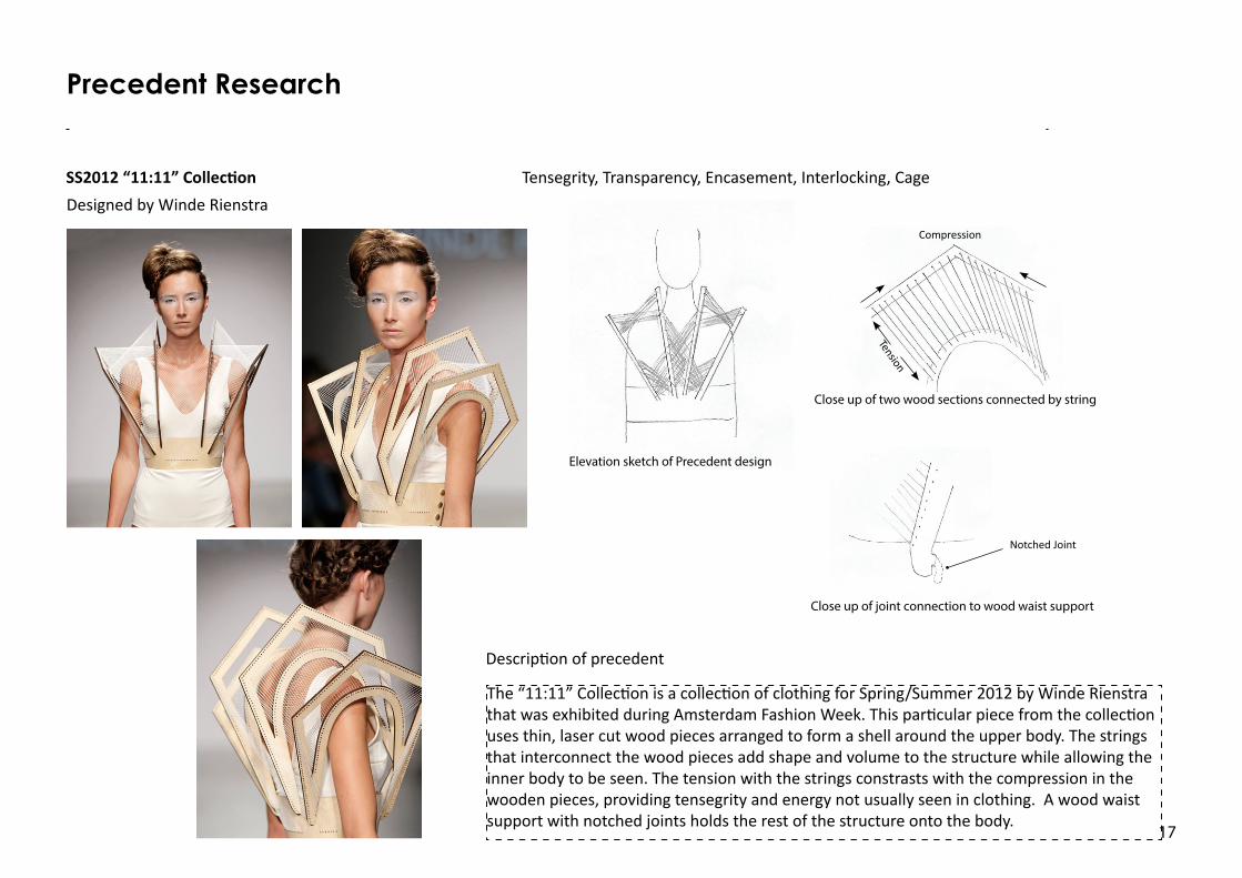
Tensegrity, Transparency, Encasement, Interlocking, Cage
The “11:11” Collection is a collection of clothing for Spring/Summer 2012 by Winde Rienstra that was exhibited during Amsterdam Fashion Week. This particular piece from the collection uses thin, laser cut wood pieces arranged to form a shell around the upper body. The strings that interconnect the wood pieces add shape and volume to the structure while allowing the inner body to be seen. The tension with the strings constrasts with the compression in the wooden pieces, providing tensegrity and energy not usually seen in clothing. A wood waist support with notched joints holds the rest of the structure onto the body.
SS2012 “11:11” Collection
Description of precedent
Precedent Research
Designed by Winde Rienstra
Elevation sketch of Precedent design
Close up of two wood sections connected by string
Close up of joint connection to wood waist support
Tension
Compression
Notched Joint
18
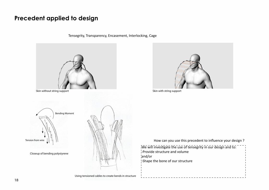
Precedent applied to design
We will investigate the use of tensegrity in our design and to:-Provide structure and volumeand/or-Shape the bone of our structure
How can you use this precedent to influence your design ?
Tensegrity, Transparency, Encasement, Interlocking, Cage
Skin without string support Skin with string support
Bending Moment
Tension from wire
Closeup of bending polystyrene
Using tensioned cables to create bends in structure
19
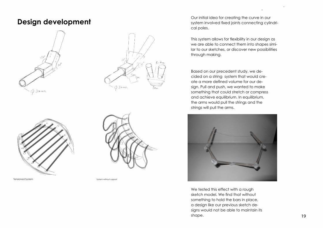
Design development
This system allows for flexibility in our design as we are able to connect them into shapes simi-lar to our sketches, or discover new possibilities through making.
Our initial idea for creating the curve in our system involved fixed joints connecting cylindri-cal poles.
Tensioned System System without support
Based on our precedent study, we de-cided on a string system that would cre-ate a more defined volume for our de-sign. Pull and push, we wanted to make something that could stretch or compress and achieve equilibrium. In equilibrium, the arms would pull the strings and the strings will pull the arms.
We tested this effect with a rough sketch model. We find that without something to hold the bars in place, a design like our previous sketch de-signs would not be able to maintain its shape.
20
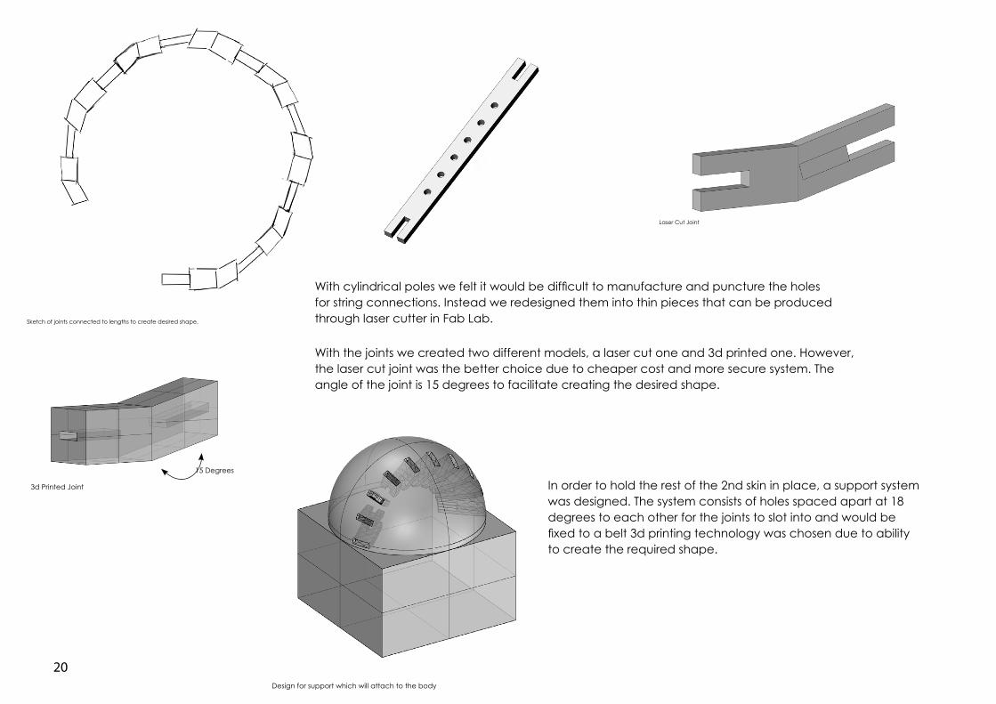
With cylindrical poles we felt it would be difficult to manufacture and puncture the holes for string connections. Instead we redesigned them into thin pieces that can be produced through laser cutter in Fab Lab.
With the joints we created two different models, a laser cut one and 3d printed one. However, the laser cut joint was the better choice due to cheaper cost and more secure system. The angle of the joint is 15 degrees to facilitate creating the desired shape.
Sketch of joints connected to lengths to create desired shape.
Laser Cut Joint
3d Printed Joint
15 Degrees
Design for support which will attach to the body
In order to hold the rest of the 2nd skin in place, a support system was designed. The system consists of holes spaced apart at 18 degrees to each other for the joints to slot into and would be fixed to a belt 3d printing technology was chosen due to ability to create the required shape.
21
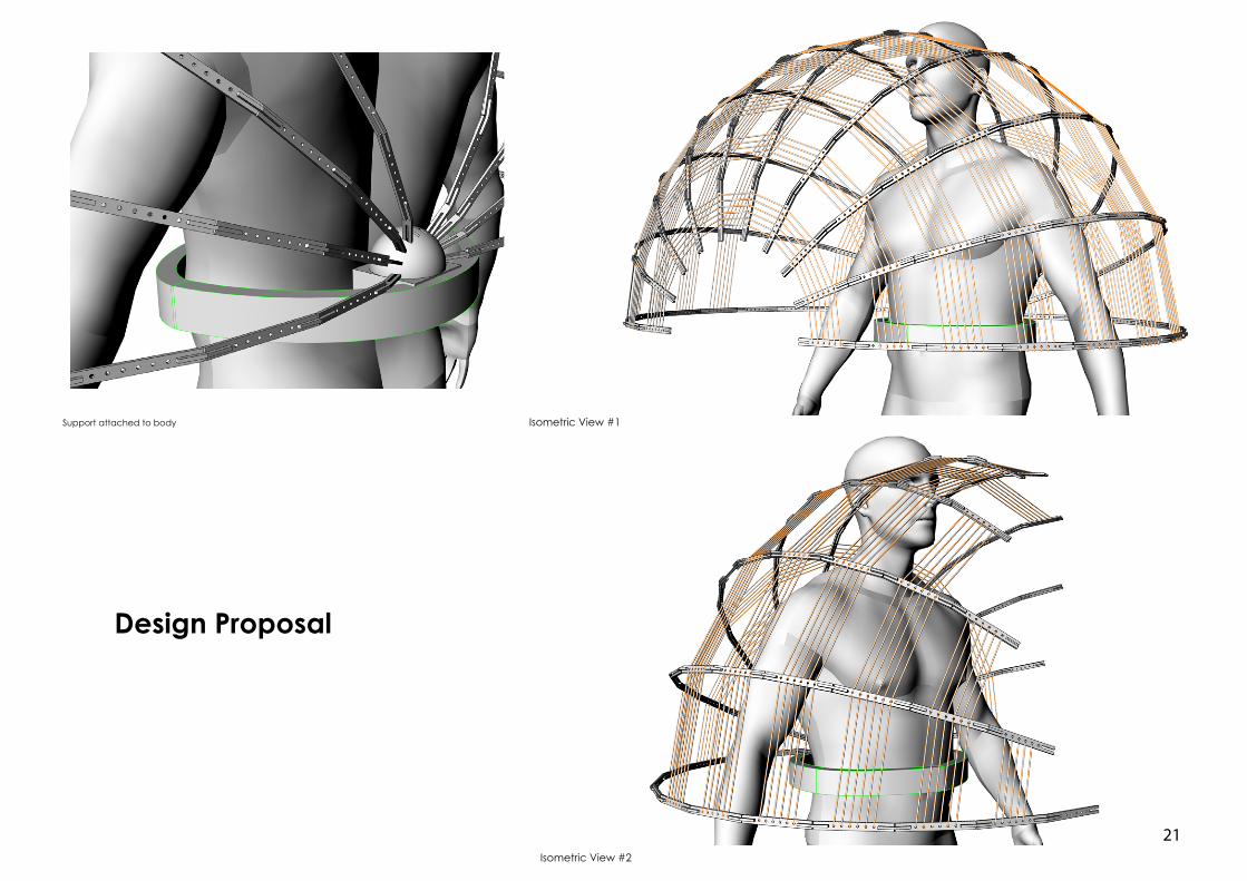
Laser Cut Joint
Isometric View #1
Isometric View #2
Support attached to body
Design Proposal
22
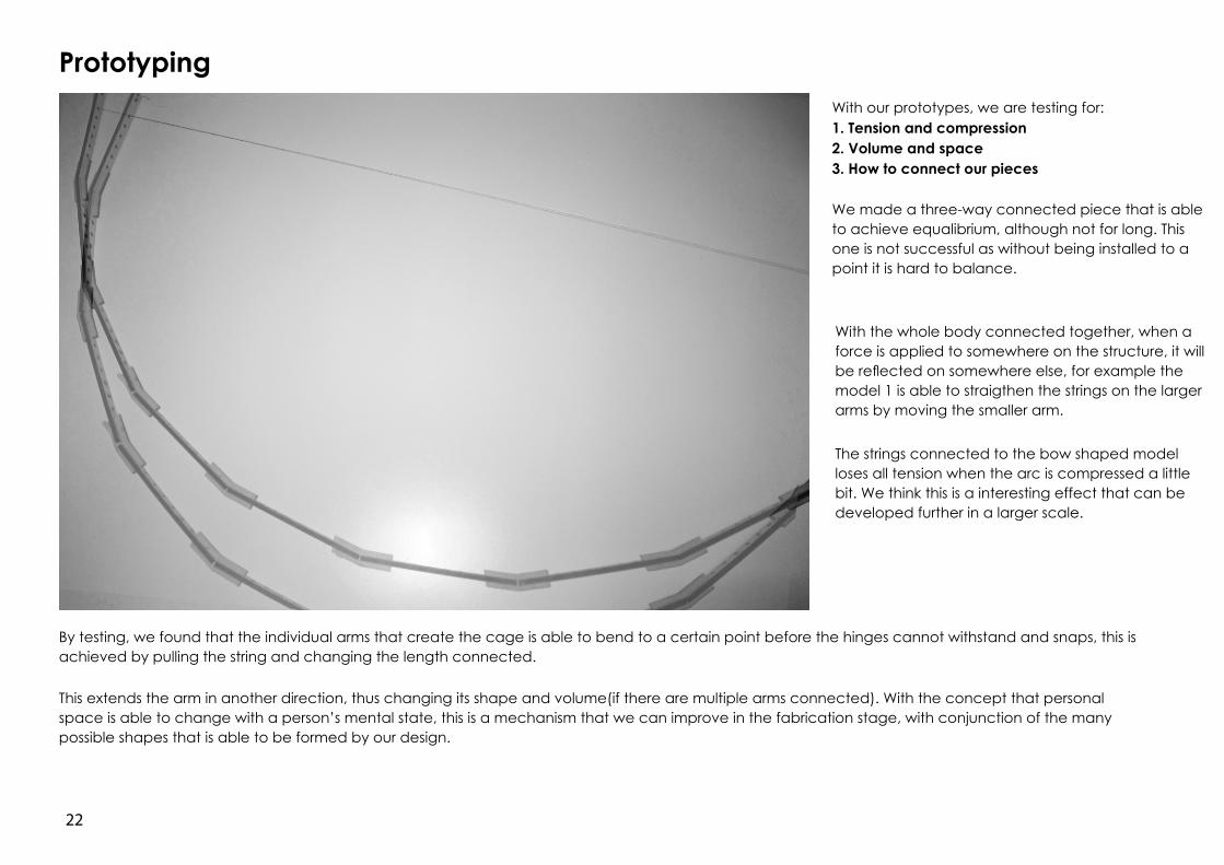
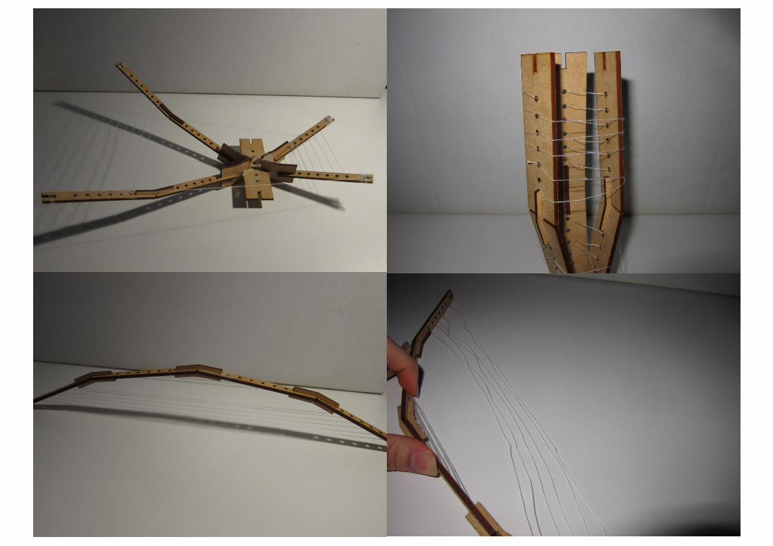
With our prototypes, we are testing for:1. Tension and compression2. Volume and space3. How to connect our pieces
We made a three-way connected piece that is able to achieve equalibrium, although not for long. This one is not successful as without being installed to a point it is hard to balance.
With the whole body connected together, when a force is applied to somewhere on the structure, it will be reflected on somewhere else, for example the model 1 is able to straigthen the strings on the larger arms by moving the smaller arm.
The strings connected to the bow shaped model loses all tension when the arc is compressed a little bit. We think this is a interesting effect that can be developed further in a larger scale.
By testing, we found that the individual arms that create the cage is able to bend to a certain point before the hinges cannot withstand and snaps, this is achieved by pulling the string and changing the length connected.
This extends the arm in another direction, thus changing its shape and volume(if there are multiple arms connected). With the concept that personal space is able to change with a person’s mental state, this is a mechanism that we can improve in the fabrication stage, with conjunction of the many possible shapes that is able to be formed by our design.
Prototyping
23
24
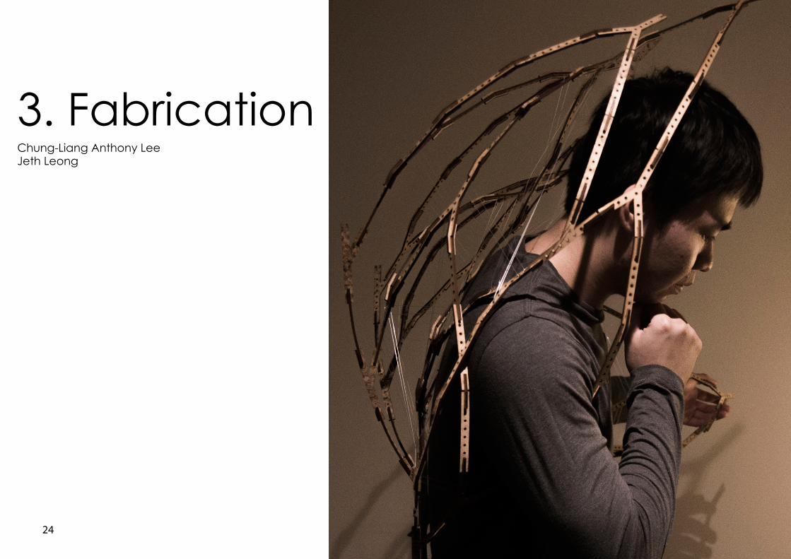
3. FabricationChung-Liang Anthony LeeJeth Leong
25
Prototype development
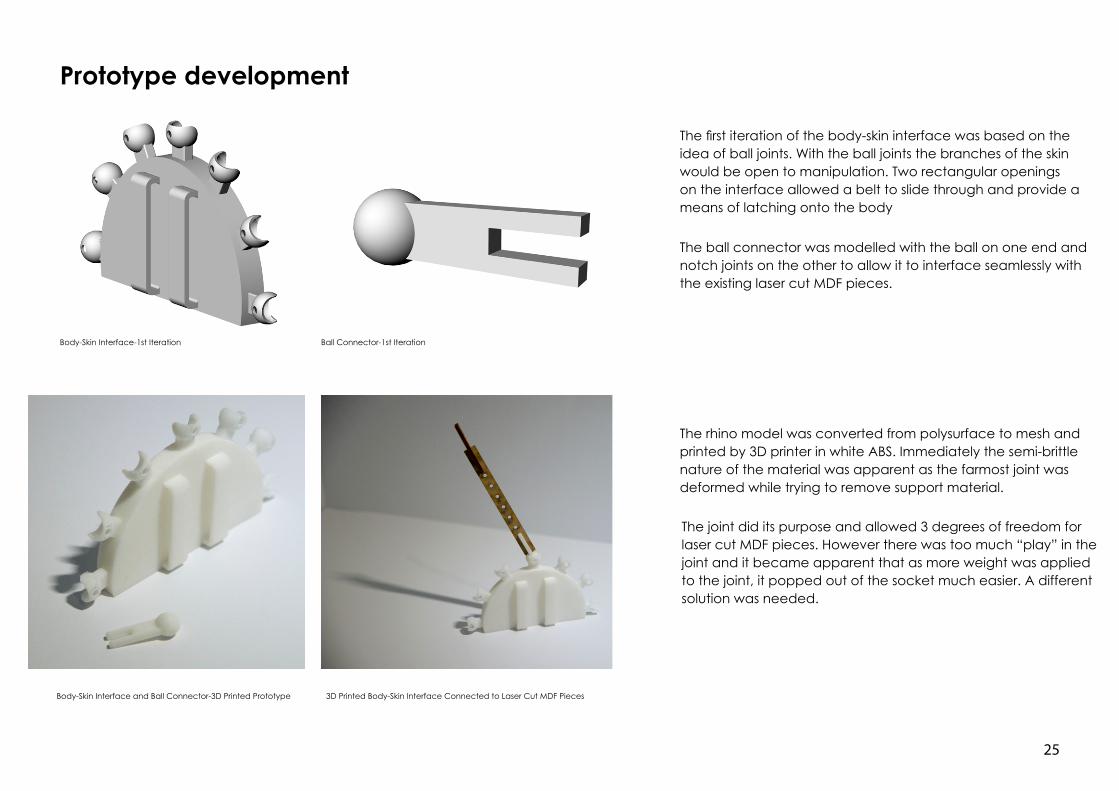
The first iteration of the body-skin interface was based on the idea of ball joints. With the ball joints the branches of the skin would be open to manipulation. Two rectangular openings on the interface allowed a belt to slide through and provide a means of latching onto the body
Body-Skin Interface-1st Iteration
The ball connector was modelled with the ball on one end and notch joints on the other to allow it to interface seamlessly with the existing laser cut MDF pieces.
Ball Connector-1st Iteration
Body-Skin Interface and Ball Connector-3D Printed Prototype 3D Printed Body-Skin Interface Connected to Laser Cut MDF Pieces
The rhino model was converted from polysurface to mesh and printed by 3D printer in white ABS. Immediately the semi-brittle nature of the material was apparent as the farmost joint was deformed while trying to remove support material.
The joint did its purpose and allowed 3 degrees of freedom for laser cut MDF pieces. However there was too much “play” in the joint and it became apparent that as more weight was applied to the joint, it popped out of the socket much easier. A different solution was needed.
26
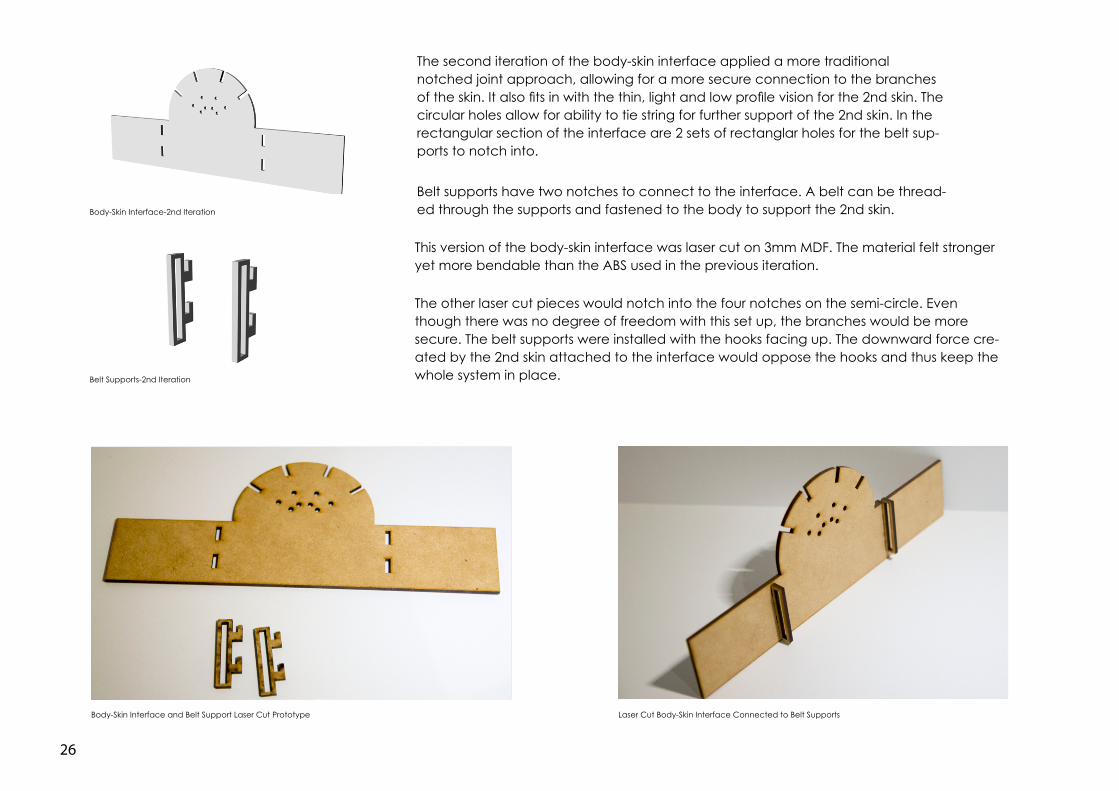
Body-Skin Interface-2nd Iteration
Belt Supports-2nd Iteration
Body-Skin Interface and Belt Support Laser Cut Prototype Laser Cut Body-Skin Interface Connected to Belt Supports
The second iteration of the body-skin interface applied a more traditional notched joint approach, allowing for a more secure connection to the branches of the skin. It also fits in with the thin, light and low profile vision for the 2nd skin. The circular holes allow for ability to tie string for further support of the 2nd skin. In the rectangular section of the interface are 2 sets of rectanglar holes for the belt sup-ports to notch into.
Belt supports have two notches to connect to the interface. A belt can be thread-ed through the supports and fastened to the body to support the 2nd skin.
This version of the body-skin interface was laser cut on 3mm MDF. The material felt stronger yet more bendable than the ABS used in the previous iteration.
The other laser cut pieces would notch into the four notches on the semi-circle. Even though there was no degree of freedom with this set up, the branches would be more secure. The belt supports were installed with the hooks facing up. The downward force cre-ated by the 2nd skin attached to the interface would oppose the hooks and thus keep the whole system in place.
27
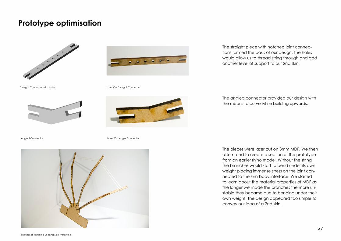
Prototype optimisation
Straight Connector with Holes Laser Cut Straight Connector
Angled Connector Laser Cut Angle Connector
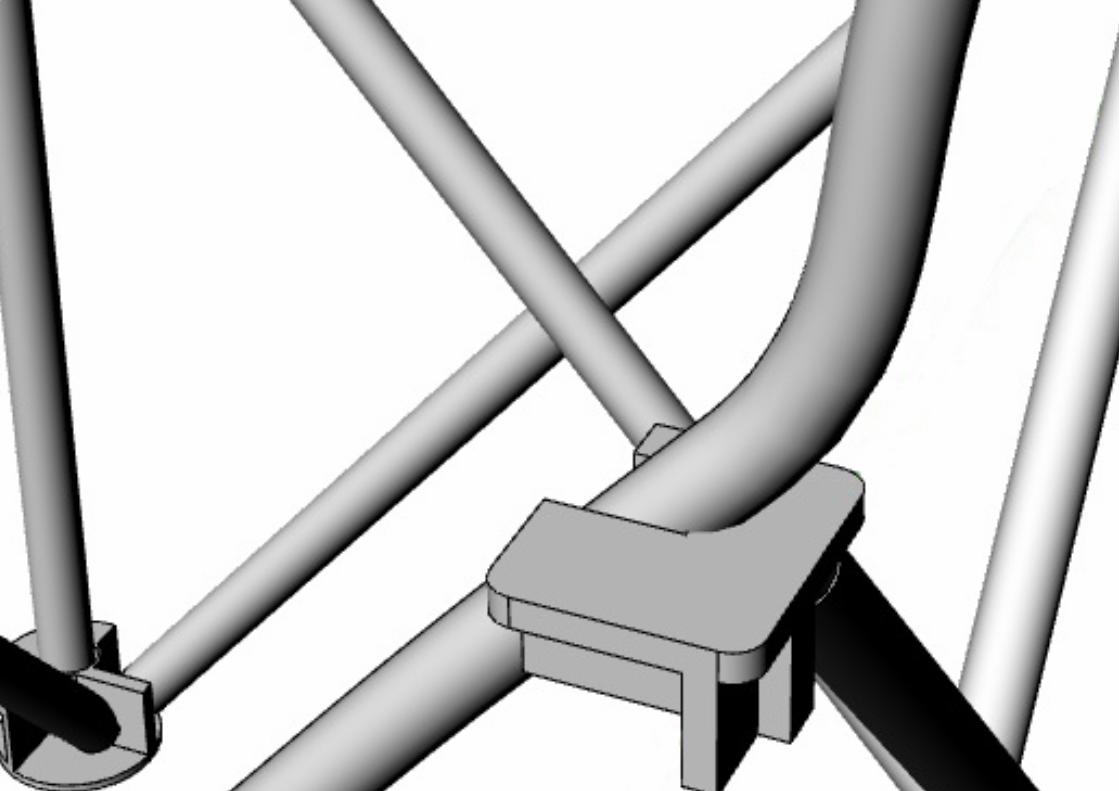
The straight piece with notched joint connec-tions formed the basis of our design. The holes would allow us to thread string through and add another level of support to our 2nd skin.
The angled connector provided our design with the means to curve while building upwards.
Section of Version 1 Second Skin Prototype
The pieces were laser cut on 3mm MDF. We then attempted to create a section of the prototype from an earlier rhino model. Without the string the branches would start to bend under its own weight placing immense stress on the joint con-nected to the skin-body interface. We started to learn about the material properties of MDF as the longer we made the branches the more un-stable they became due to bending under their own weight. The design appeared too simple to convey our idea of a 2nd skin.
28
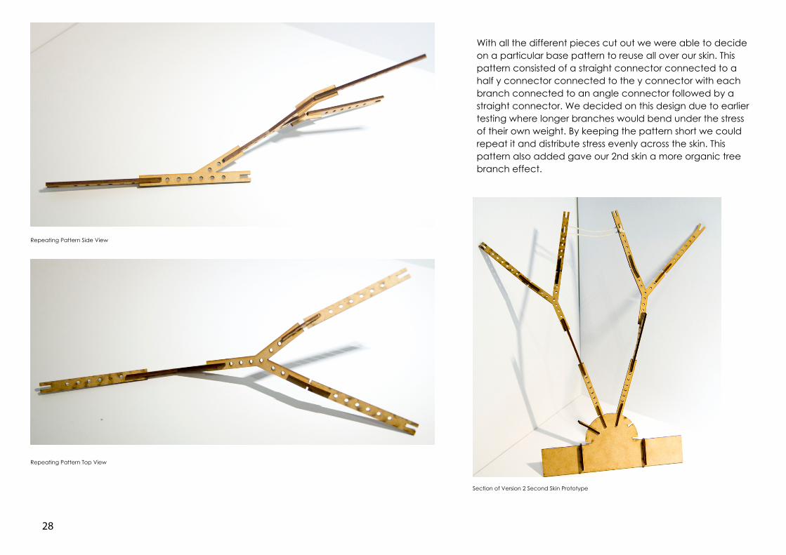
Repeating Pattern Side View
Repeating Pattern Top View
With all the different pieces cut out we were able to decide on a particular base pattern to reuse all over our skin. This pattern consisted of a straight connector connected to a half y connector connected to the y connector with each branch connected to an angle connector followed by a straight connector. We decided on this design due to earlier testing where longer branches would bend under the stress of their own weight. By keeping the pattern short we could repeat it and distribute stress evenly across the skin. This pattern also added gave our 2nd skin a more organic tree branch effect.
Section of Version 2 Second Skin Prototype
29
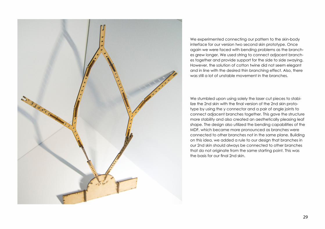
We experimented connecting our pattern to the skin-body interface for our version two second skin prototype. Once again we were faced with bending problems as the branch-es grew longer. We used string to connect adjacent branch-es together and provide support for the side to side swaying. However, the solution of cotton twine did not seem elegant and in line with the desired thin branching effect. Also, there was still a lot of unstable movement in the branches.
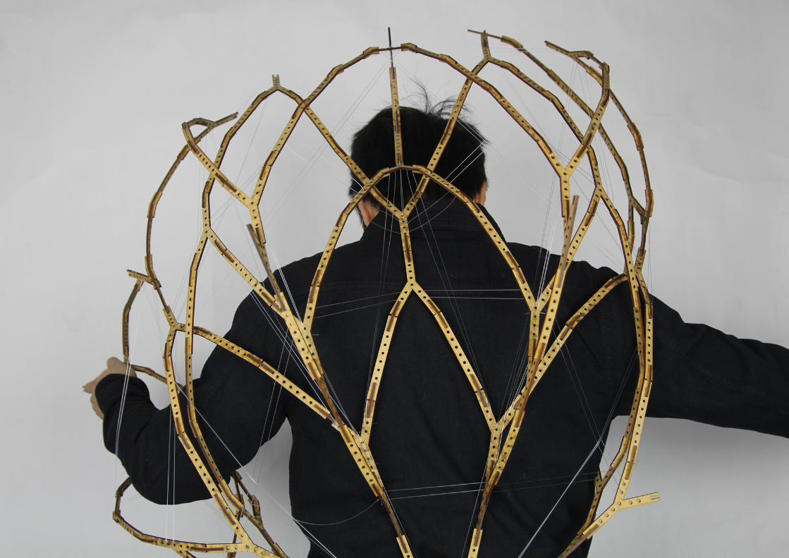
We stumbled upon using solely the laser cut pieces to stabi-lize the 2nd skin with the final version of the 2nd skin proto-type by using the y connector and a pair of angle joints to connect adjacent branches together. This gave the structure more stability and also created an aesthetically pleasing leaf shape. The design also utilized the bending capabilities of the MDF, which became more pronounced as branches were connected to other branches not in the same plane. Building on this idea, we added a rule to our design that branches in our 2nd skin should always be connected to other branches that do not originate from the same starting point. This was the basis for our final 2nd skin.
30
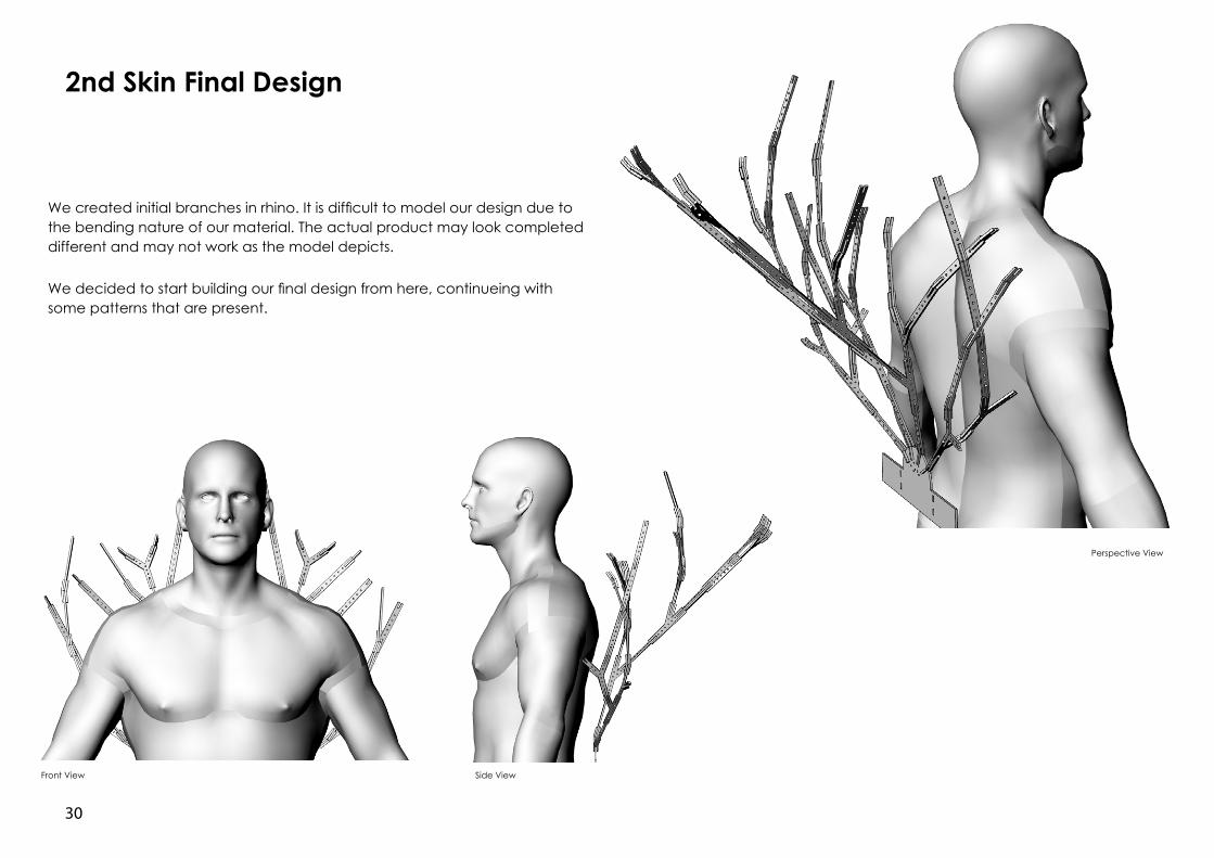
2nd Skin Final Design
Front View Side View
Perspective View
We created initial branches in rhino. It is difficult to model our design due to the bending nature of our material. The actual product may look completed different and may not work as the model depicts.
We decided to start building our final design from here, continueing with some patterns that are present.
31
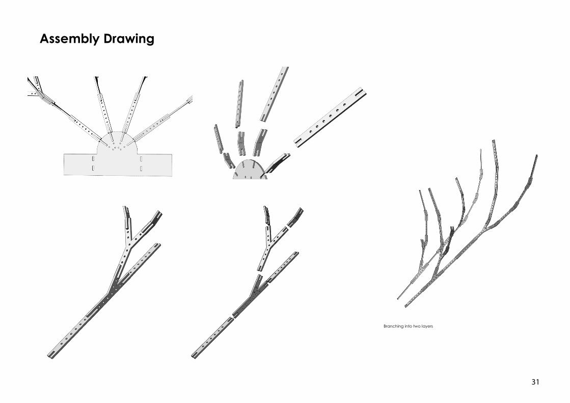
Branching into two layers
Assembly Drawing
32
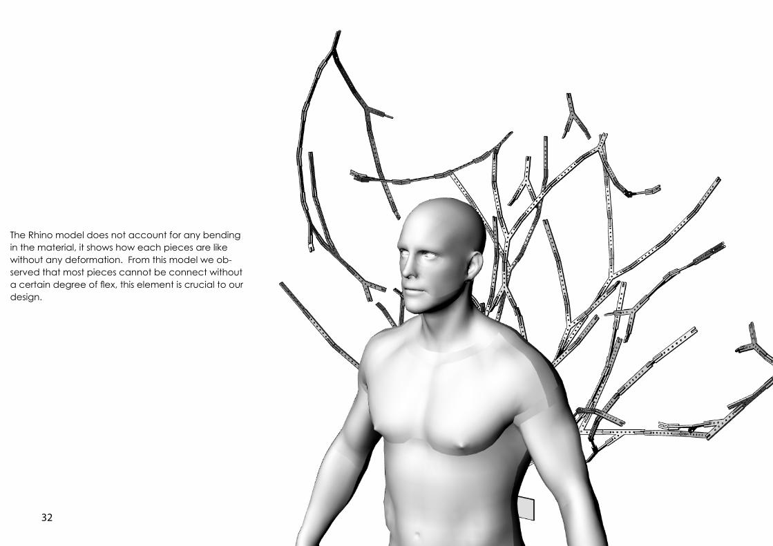
The Rhino model does not account for any bending in the material, it shows how each pieces are like without any deformation. From this model we ob-served that most pieces cannot be connect without a certain degree of flex, this element is crucial to our design.

33
34
35
36
37
4. Reflection
38
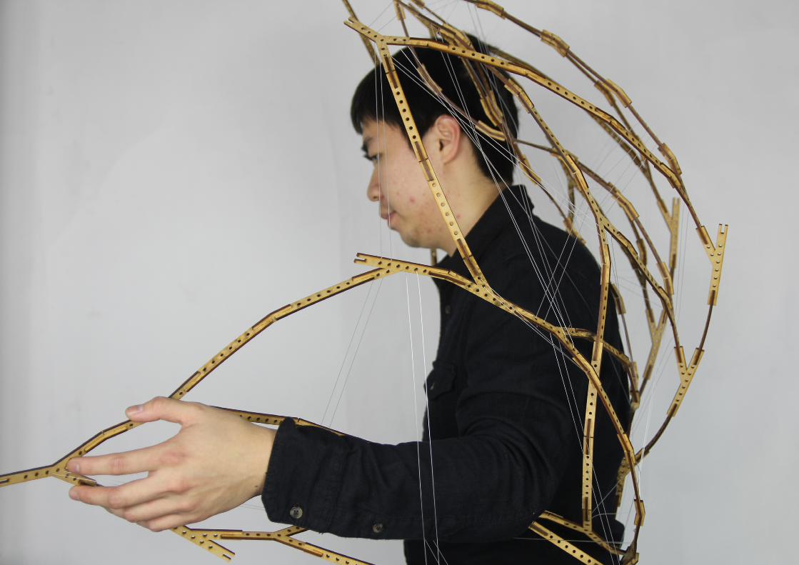
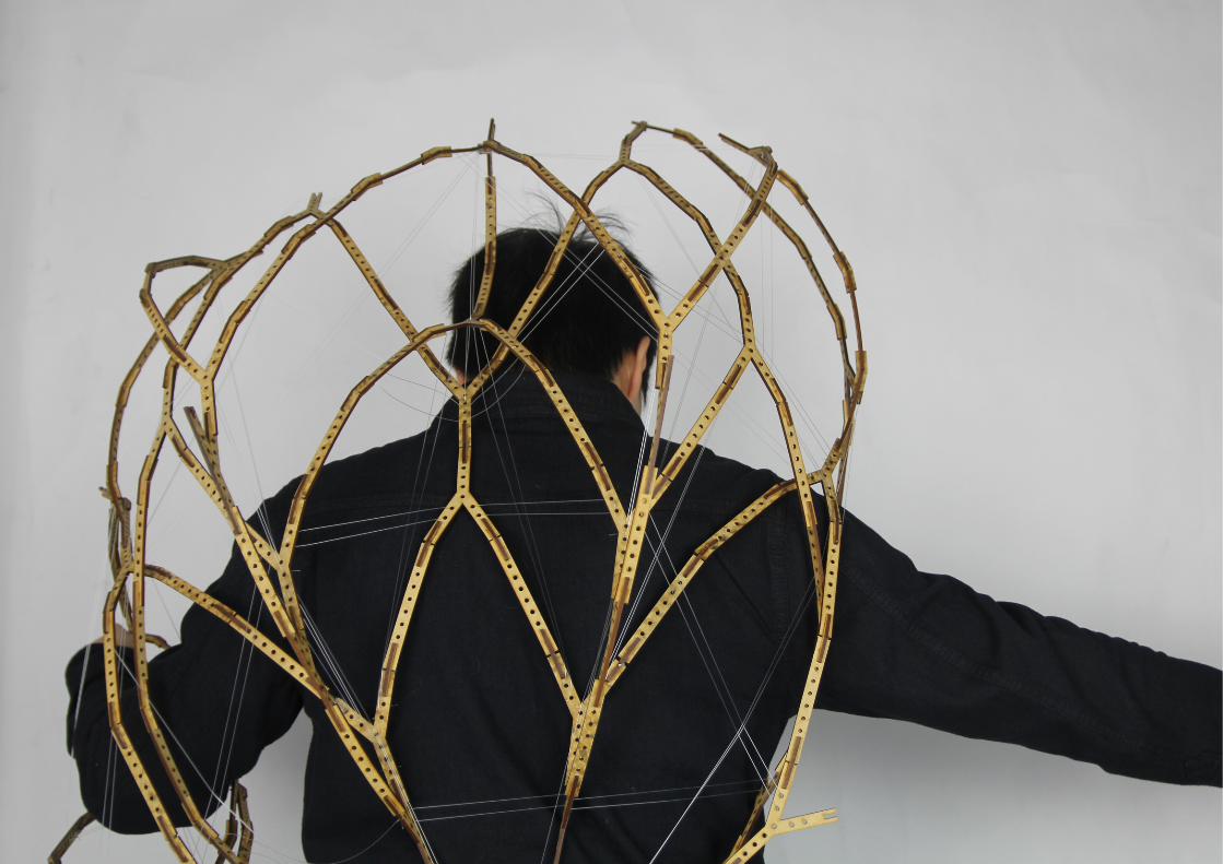
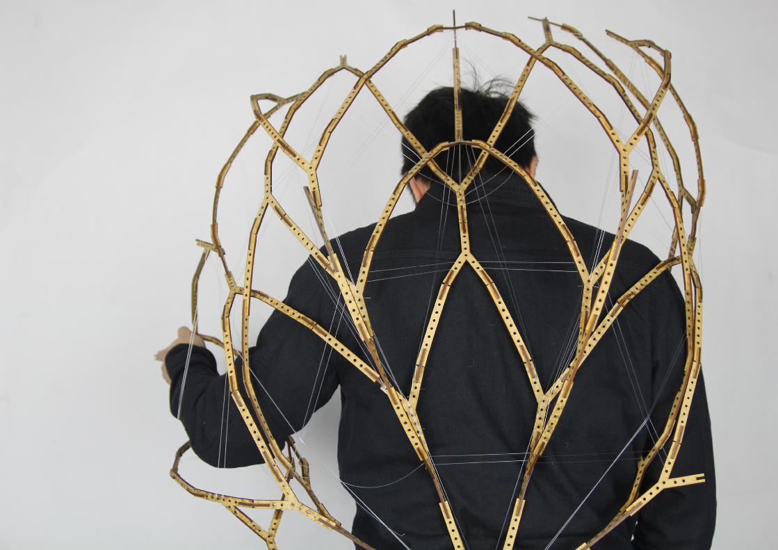
To finalise our deisgn, we built upon the model
after M3 until the structure is unable to be supported.
Being fragile already, it became even more suspect-
able to damage, in-fact small parts of the model are
broken and will need to be fix, luckily it is still able to
hold up on its own.
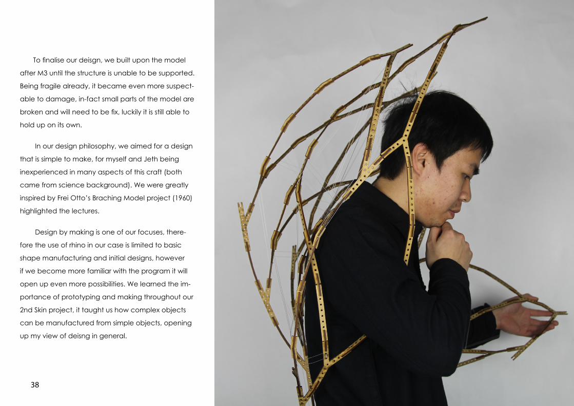
In our design philosophy, we aimed for a design
that is simple to make, for myself and Jeth being
inexperienced in many aspects of this craft (both
came from science background). We were greatly
inspired by Frei Otto’s Braching Model project (1960)
highlighted the lectures.
Design by making is one of our focuses, there-
fore the use of rhino in our case is limited to basic
shape manufacturing and initial designs, however
if we become more familiar with the program it will
open up even more possibilities. We learned the im-
portance of prototyping and making throughout our
2nd Skin project, it taught us how complex objects
can be manufactured from simple objects, opening
up my view of deisng in general.
39
40
41
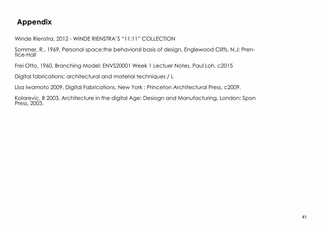
Appendix
Winde Rienstra, 2012 - WINDE RIENSTRA’S “11:11” COLLECTION
Sommer, R., 1969, Personal space:the behavioral basis of design, Englewood Cliffs, N.J: Pren-tice-Hall
Frei Otto, 1960, Branching Model: ENVS20001 Week 1 Lectuer Notes, Paul Loh, c2015
Digital fabrications: architectural and material techniques / L
Lisa Iwamoto 2009, Digital Fabrications. New York : Princeton Architectural Press, c2009.
Kolarevic, B 2003, Architecture in the digital Age: Desiogn and Manufacturing, London: Spon Press, 2003.