Embed Size (px)
Citation preview

Module3 Page 1
Module 3: Onsite Practices
ESC Practices & Minimum Standards
Chapter 3 in the 1992 ESCHB is organized in such a way that it groups certain structural practices (as shown
below).
Road stabilization practices prevent the tracking of dirt onto public roads, while sediment barriers filter sediment
laden water. Dikes and diversion either: split up drainage area, reduce them in size, or prevent stormwater from
entering an area. Sediment traps and basins filter water prior to discharge. Flumes allow stormwater to safely
1 Safety Fence
2-3 RoadStabilization
• ConstructionEntrance
• ConstructionRoadStabilization
4-8 SedimentBarriers
•Straw BaleBarrier
•Silt fence
•Brush Barrier
•Storm DrainInlet Protection
•Culvert InletProtection
9-12 Dikes andDiversions
•TemporaryDiversion Dikes
•Temporary FillDiversions
•TemporaryRight-of-WayDiversions
•Diversions
13-14Sediment Trapsand Basins
• TemporarySedimentTrap
• TemporarySedimentBasin
15-16 Flumes
• Temporary SlopeDrains
• Paved Flumes
17-21 Waterwayand OutletProtection
• StormwaterConveyanceChannel
• Outlet Protection
• Riprap
• Rock Check Dams
• Level Spreader
22-27 StreamProtection
•Vegetative StreambankStabilization
•Structural StreambankStabilization
•Temporary VehicularCrossing
•Utility Stream Crossing
•Dewatering Structures
•Turbidity Curtain
28 SubsurfaceDrain
39 Dust Control

M
flow down slopes. Waterway, outlet and stream protection protect onsite channels, outlets and off-site channels,
respectively. Finally, excess water on a site can also be removed by subsurface drain.
Each chapter (practice) in Section 3 of the ESCHB is organized into a number of sections:
1. Definition
2. Purpose
3. Condition where practice applies
4. Planning considerations
5. Design criteria
6. Construction specifications
7. Maintenance
http://www.deq.virginia.gov/Programs/Water/StormwaterManagement/Publications/ESCHandbook.aspx
DEQ realizes that there are many more sediment control measures on the market; however, the practices in the
1992 ESCHB are generic and non proprietary. If a proponent of a project wishes to use a proprietary practice, this
practice will need to be approved for use in that locality. Approval is done at the locality level, often in consultation
with the local DEQ representative.
The following is a brief review of some selected sediment control practices.
3.02 Temporary Stone Construction Entrance (CE)
Construction entrances are stone “runways” located at the points of
vehicular ingress and egress on a construction site.
Meant to reduce soil the transport onto public roads & paved areas. 6 inch thick – 12 feet wide & 70 feet long Must use filter cloth underneath VDOT #1 stone Wash rack may be used if water is carried to settling area MS-17
TAKE AWAY POINTS:
Street requires frequent cleaning - Mud must be removed from paved area at the end of eachday by shovel & broom
Stone must be replaced or cleaned frequently
odule3 Page 2
Mo
3.03 Construction Road Stabilization (CRS)
During wet weather, temporary stabilization with stone w
14 feet wide – one way; 20 feet wide two way traffic MS-17 & MS-1
3.05 Silt Fence (SF)
A silt fence is a temporary sediment barrier constructed of filter fabric and
supported by pests and sometimes wire.
as a first step measure (MS-4) and placed across or at the toe of a slope.
Used to intercept sheet and rill flow; not concentrated. (i.e. flow must be Drainage area limited to ¼ acre
be wider that 100 feet). Height above ground; Min=16” &
3.0
Thinc
onstruction Road Stabilization (CRS)
During wet weather, temporary stabilization with stone will reduce the mud and potential erosion
one way; 20 feet wide two way traffic
A silt fence is a temporary sediment barrier constructed of filter fabric and
supported by pests and sometimes wire. As perimeter control they often installed
4) and placed across or at the toe of a slope.
Used to intercept sheet and rill flow; not concentrated. (i.e. flow must be ≤ 1 CFS)¼ acre for 100 linear feet of barrier (total drainage area behind a silt fence cannot
; Min=16” & Max= 34
uce the mud and potential erosion
1 CFS)total drainage area behind a silt fence cannot
TAKE AWAY POINTS:
Sheet flow only 4” deep and 4” wide trench on upslope side Cleanout (½ barrier height) Check Stake spacing Must be removed at the end of a project per MS
4” deep and 4” wide trench on upslope side 8” of fabric in ditch
Must be removed at the end of a project per MS-18.
7 Storm Drain Inlet Protection (IP)
e 1992 ESCHB shows several types of storm drain inlet protectionluding drop inlets and curb inlets. Drainage area size limitation is 1 acre.
• Silt fence Type: 2 X 4 stakes for vertical and horizontalEntrench fabric 12 inches around inlet
• Gravel and Wire: ½” wire mesh over inlet• Concrete Block: ½” wire mesh over inlet; place at least 12 inches of stone over the wire• MS-10 requires that inlet protection is provided
stabilization of the area.
Protection (IP)
types of storm drain inlet protectionDrainage area size limitation is 1 acre.
2 X 4 stakes for vertical and horizontal; spaced 3 feet apartbric 12 inches around inlet
½” wire mesh over inlet; place at least 12 inches of stone over the wire½” wire mesh over inlet; place at least 12 inches of stone over the wire
10 requires that inlet protection is provided on all inlets that are operational before final/permanent
stone over the wire½” wire mesh over inlet; place at least 12 inches of stone over the wire
on all inlets that are operational before final/permanent
TAKE AWAY POINTS:
Purpose – keep sediment out of storm sewer & prevent the need to vacuum and/or flush afterkeep sediment out of storm sewer & prevent the need to vacuum and/or flush afterkeep sediment out of storm sewer & prevent the need to vacuum and/or flush after
dule3
construction
Page 3
3.08 Culvert Inlet Protection (CIP)
Culvert inlet protection prevents sediment from entering into the culvert.
Types of culvert inlet protection include: Silt Fence:
Maximum life = 3 monthsMinimum height = 16”; ma
Sediment Trap:Constructed per approved plan andToe of riprap no closer than 24” from opening
sediment from entering into the culvert.
include:
aximum life = 3 monthsheight = 16”; maximum height = 34”
Constructed per approved plan and specificationsToe of riprap no closer than 24” from opening
TAKE AWAY POINTS:
Culvert inlet protection is required by MSCulvert inlet protection is required by MS-10 & must be removed at the project’s end (MS10 & must be removed at the project’s end (MS-18).
3.09 Temporary Diversion Dike (DD)
This is a ridge of compacted soil which is either used to divert water away from
the project area, or divert water on-site to sediment trapping devi
conveyances, or stabilized outlets (MS-11).
Often constructed as first step measure (MS They have a maximum drainage area size of 5 acre.
3.09 Temporary Diversion Dike (DD)
This is a ridge of compacted soil which is either used to divert water away from
site to sediment trapping devices, water
11).
ucted as first step measure (MS-4) or later on when site conditions change.They have a maximum drainage area size of 5 acre.
later on when site conditions change.
TAKE AWAY POINTS:
Must be stabilized immediately after construction (MS They have a maximum life of 18 months.
Must be stabilized immediately after construction (MS-5)They have a maximum life of 18 months.
Module3 Page 4

3.10 Temporary Fill Diversions (FD)
This is a diversion used for active (earth) fill areas. They address MS-7in requiring stable fill slopes that are non-erodible and MS-8 whichrequires any concentrated runoff be directed down a slope in a controlled manner.
Typically constructed at the end of the work day. Minimum height = 9 inches They have a maximum life span of one week; thus, do NOT need to be stabilized. Constructed to divert water from the slope to a stable outfall (MS-11).
3.11 Temporary Right-of-Way Diversions (RWD)
This is a ridge of compacted soil or loose gravel placed across a disturbedright-of-way. Practice is often seen on utility projects in hilly terrain.
Constructed to reduce the flow length and divert the water to a stable outlet (MS-11). Min height 18 inches Needs proper spacing (p.63 of ESCH) Mountable by vehicles
TAKE AWAY POINTS:
Remember Module 1 regarding slope steepness and length. If you see rills or small gullies forming, consider using this “speed bump”
3.12 Diversion (DV)
This is a permanent channel with a ridge on the lower (downslope) side.
They are constructed to reduce slope length, divert stormwater runoff
and are sometimes used as perimeter control.
They must terminate in a stabilized outlet (MS-11) They must be designed to convey the runoff from a 10-year storm (MS-19).
TAKE AWAY POINTS:
Must be stabilized immediately (MS-5) and prior to being made operational
Module3 Page 5
3.13 Temporary Sediment Trap (ST)
This is a small ponded area usually formed by constructing an earthen
embankment along a slope or small drainage area. A stone weir/outlet is used to drain to drain this
defined time. They are generally used as part of the perimeter controls for the project (MS
Per MS-6, traps can only treat runoff from Storage capacity = 134 cubic yds./acre Must include 50% dry storage & 50% wet storage volume
3.14 Temporary Sediment Basin (SB)
Sediment basins consist of a temporary barrier or dam with an engineeredoutfall structure that releases the water in a controlledstructure is usually constructed across a drainage way at the low end of the project andqualified professional. They are generally used as part of the perimeter controls for the project (MSbe stabilized before made functional (MS
Per MS-6, must be used to treat stormwater runoff from areas that are 3 acres or Storage capacity = 134 cubic yds./acre Must include 50% dry storage & 50% wet storage volume
ea usually formed by constructing an earthen
embankment along a slope or small drainage area. A stone weir/outlet is used to drain to drain this
They are generally used as part of the perimeter controls for the project (MS
can only treat runoff from less than 3 acresStorage capacity = 134 cubic yds./acreMust include 50% dry storage & 50% wet storage volume.
B)
Sediment basins consist of a temporary barrier or dam with an engineeredoutfall structure that releases the water in a controlled manner. The
s usually constructed across a drainage way at the low end of the project and mustThey are generally used as part of the perimeter controls for the project (MS
be stabilized before made functional (MS-5).
to treat stormwater runoff from areas that are 3 acres orStorage capacity = 134 cubic yds./acreMust include 50% dry storage & 50% wet storage volume.
embankment along a slope or small drainage area. A stone weir/outlet is used to drain to drain this pond over a
They are generally used as part of the perimeter controls for the project (MS-4).
must be designed by aThey are generally used as part of the perimeter controls for the project (MS-4) and need to
to treat stormwater runoff from areas that are 3 acres or more
TAKE AWAY POINTS:
They have a maximum life of 18 months. Cleaned out when sediment reaches half the volume of the wet storage Mark the riser pipe at the clean out volume Make sure the low flow orifice is blocked during construction if structure will be converted
permanent SWM pond after construction
They have a maximum life of 18 months.Cleaned out when sediment reaches half the volume of the wet storage
clean out volumeMake sure the low flow orifice is blocked during construction if structure will be convertedpermanent SWM pond after constructionMake sure the low flow orifice is blocked during construction if structure will be converted
TAKE AWAY POINTS:
Minimum Standard 5 requires they be They have a maximum life of 18 months. Cleaned out when sediment reaches half the volume of the wet storage Determine a mark/measurement = half the wet storage volume Place sediment where it will NOT run back into the trap.
Minimum Standard 5 requires they be stabilized immediatelymaximum life of 18 months.
Cleaned out when sediment reaches half the volume of the wet storageDetermine a mark/measurement = half the wet storage volumePlace sediment where it will NOT run back into the trap.
Module3
3.15 Temporary Slope Drain (TSD)
Temporary slope drains consist of flexible tubing that are
conduct concentrated runoff safely from the top to the bottom
without causing erosion on or below the slope
Temporary slope drains consist of flexible tubing that are installed on slopes and
conduct concentrated runoff safely from the top to the bottom of the slope
without causing erosion on or below the slope.
Page 6

M
They are required per MS-8. Maximum Drainage area is 5 acres Need to be sized according to table 3.15
3
P
c
c
3
T
f
Maximum Drainage area is 5 acresNeed to be sized according to table 3.15-A of ESCH
P
c
c
3
TAKE AWAY POINTS:
Entrance of the drain is located at a low point Slope drain (pipe) must be properly anchored Outlet protect must be installed
Entrance of the drain is located at a low pointSlope drain (pipe) must be properly anchored
utlet protect must be installed at the bottom
.16 Paved Flumes (PF)
aved flumes are permanently concrete lined channels constructed to conduct
oncentrated stormwater runoff from the top to the bottom of a slope without
ausing erosion on or below the slope.
• They are required per MS• Must have curtain walls top and• Expansion joints are required every 90 feet
aved flumes are permanently concrete lined channels constructed to conduct
oncentrated stormwater runoff from the top to the bottom of a slope without
ausing erosion on or below the slope.
They are required per MS-8.Must have curtain walls top and bottomExpansion joints are required every 90 feet
TAKE AWAY POINTS:
Outlet protection & energy dissipaterOutlet protection & energy dissipater
odule3
.17 Stormwater Conveyance Channels (SCC)
hese are permanent channels which can be grass, rip
low without erosion. They may be used
Required to convey flows as per Manmade must handle peak flow of 10 yr. Natural must handle peak flow of 2 yr. storm Must include outlet protection and discharge into an adequate channel
.17 Stormwater Conveyance Channels (SCC)
which can be grass, rip-rap, or concrete and are designed to carry concentrated
may be used in combination with (permanent) diversions (3.12).
as per MS-19 and must be stabilized before operational (MSManmade must handle peak flow of 10 yr. stormNatural must handle peak flow of 2 yr. stormMust include outlet protection and discharge into an adequate channel
Page 7
designed to carry concentrated
in combination with (permanent) diversions (3.12).
operational (MS-5).

M
3.18 Outlet Protection (OP)
In order to reduce the erosive forces, MS-11 requires outlet protection in areas where stormwater either: a) leaves
the project site or b) exits channels, stilling basins and/or storm drain outlets.
• Filter cloth under rock• Provides a smooth transition with natural channel
3.
Th
flo
3.
Th
ac
3.
di
TAKE AWAY POINTS:
Installed at 0% grade Excavate, lay filter cloth, then install rock to design elevation, length and width
20 Rock Check Dam (CD)
ese are small temporary stone dams constructed across drainage ditches to reduce the velocity of concentrated
ws; thus reducing the potential for erosion in swales and ditches.
Two stone sizes depending on drainage area Max. height is 3 feet and middle should be 6 inches lower
TAKE AWAY POINTS:
Remove accumulated sediment when it exceeds half the height of the dam Dispose/spread sediment proper Check dams are removed at the end of a project (MS 18).
odule3 Page 8
26 Dewatering Structure (DS)
ese are temporary settling and filtering devices for water that is discharged from dewatering (pumping)
tivities. Installed as per MS-11 & MS-16c.
• Storage capacity (ft.3) should = 16 x pump discharge capacity (GPM)• Clean-out at 1/3 the capacity
27 Turbidity Curtain (TC) -This is a floating geo-textile material which minimizes sediment transport from a
sturbed area adjacent to or within a body of water. Installed as per MS-12 and MS-14.

Module3
Stablization & Vegetation
As we learned in module 1, good vegetation is 90+% effective in preventing erosion by protecting against raindrop
impact. It also slows the runoff velocity and filters stormwater. Lastly, in the long run, it is less costly then
structural practices, due to both capital and maintenance costs.
The ESC Plan should also consider preservation of existing vegetation, as it will serve to do the following:
lessen construction costs, provide existing/native vegetation, and reduce the area disturbed (important
3.30 Topsoil (TO)
Topsoiling is the method of stripping, storing and spreading the surface layer of disturbed soil in order to obtain a
more desirable planting and growing medium after a project area has been
Stockpiles must be stabilized (sediment barrier and/or seeding) Any stockpiles off-site must be inspected topsoil is spread to a minimum depth of 2” on 3:1 or steeper slopes and 4” on flatter A soil test is an inexpesive way to determine the proper amounts of nutrients need for plant establishement
29-30SeedbedPreparation
• Surfaceroughening
• Top soiling
31-34VegetationEstablishment
• Temporaryseeding
• Permanentseeding
• Sodding• Bermuda &
zoysiagrassestablishment
As we learned in module 1, good vegetation is 90+% effective in preventing erosion by protecting against raindrop
impact. It also slows the runoff velocity and filters stormwater. Lastly, in the long run, it is less costly then
to both capital and maintenance costs.
The ESC Plan should also consider preservation of existing vegetation, as it will serve to do the following:
provide existing/native vegetation, andreduce the area disturbed (important for infiltration & SWM practices).
Topsoiling is the method of stripping, storing and spreading the surface layer of disturbed soil in order to obtain a
more desirable planting and growing medium after a project area has been completed.
(sediment barrier and/or seeding) in accordance with MS2site must be inspected and stabilized as well.
topsoil is spread to a minimum depth of 2” on 3:1 or steeper slopes and 4” on flatterA soil test is an inexpesive way to determine the proper amounts of nutrients need for plant establishement
35-36 Mulches
• Mulching• Soil
stabilization,blankets andmatting
37-38 OtherVegetativeControls
• Trees,shrubs,vines andgroundcovers
• Treepreservationandprotection
39 Dustcontrol
Page 9
As we learned in module 1, good vegetation is 90+% effective in preventing erosion by protecting against raindrop
impact. It also slows the runoff velocity and filters stormwater. Lastly, in the long run, it is less costly then
The ESC Plan should also consider preservation of existing vegetation, as it will serve to do the following:
Topsoiling is the method of stripping, storing and spreading the surface layer of disturbed soil in order to obtain a
in accordance with MS2.
topsoil is spread to a minimum depth of 2” on 3:1 or steeper slopes and 4” on flatter slopesA soil test is an inexpesive way to determine the proper amounts of nutrients need for plant establishement
39 Dustcontrol

M
TS3.31 Temporary Seeding (TS)
A good vegetative cover is approximately 90% to 100% efficient in reducing erosion and is by far the least
expensive method in erosion and sediment control. This practice includes the establishment of a temporary
vegetative cover on disturbed areas by seeding appropriate, rapidly growing annual plants
As per MS-1, temporary soil stabilization shall be applied within seven days to denuded areas that may notbe at final grade but will remain dormant for longer than 14 days.
Permanent stabilization shall be applied to areas that are to be left dormant for more than one year.
3
A
s
e
TAKE AWAY POINTS: Money spent on temporary seeding can pay for itself by reducing maintenance
costs of the yemporay sediment control practices and can prevent damage on or off-site from
sediment deposition.
odule3 Page 10
PS
.32 Permanent Seeding (PS)
s inspectors we are concerned about the proper execution of the erosion and
ediment control plan including: a) proper site preparation, b) the seeding process, c) mulching, d) plant
stablishment and maintenance, and e) any ongoing erosion during the plant establishment phase.
soil should does not contain large amounts of rocks, woody materials, or construction debris
Only, certified seed should be used
seed is spread uniformly over the site; an
site should be properly mulched (see 3.35).
TAKE AWAY POINTS:
Permanent vegetation shall not be considered established until a ground cover is achieved
that is uniform (e.g., evenly distributed), mature enough to survive, and will inhibit erosion
Individuals lots in residential construction have 2 options:

M
MU
3.33 Sodding (SO)
Sodding is a specialty installation where establishment of vegetation is critical (such as high maintenance orslopes). When installed, inspections should ensure:
• Sod is laid in staggered rows• Sod is tightly butted against each other• Sod installed on steep slopes is anchored
3.35 Mulch (MU)
Mulches are generally used in combination with permanent seeding or
during periods when the area cannot be seeded (but a ground cover is required). The two major purposes forusing mulch are to:
protect the soil from raindrop impacts and provide a favorable microclimate for seed germination and plant establishment.
Types of mulch include: straw, hay, corn stalks, wood chips, bark, and fiber mulch.
#1 choice of mulch is straw – applied at 2 tons/acre Fiber mulch – applied at 500-750 lbs/acre over straw mulch
Sod must be installed within 36 hours of harvesting
TAKE AWAY POINTS:
If sodding occurs during very dry weather, subsurface must be sprayed/wetted before installation
odule3 Page 11
TAKE AWAY POINTS: Mulch can also be used as a temporary ground cover to reduce erosion

Module3 Page 12
BM
3.36 Blankets & Matting (BM)
Soil stabilization blankets are protective coverings or mat that are placed on topof planting areas located on steep slopes, channels or shorelines. They aregenerally divided into two classes:
Treatment 1 is a (bio) degradable blanket used to protect the soil from raindrop impacts on slopes steeperthan 3:1.
Treatment 2 mats are non-degradable plastic structures which can be filled and planted. These matsbecome part of the soil surface and are resistant to the high energy generated by stormwater
3.39 Dust Control (DC)
Fugitive dust can be a significant cause in air pollution and it’s important to control emissions. Excessive dust can
contribute to health problems of neighbors, especially if they have pre-existing respiratory problems. Dust can
also lead to complaints from deposits on cars, houses and other property. Major sources of dust are bare areas,
haul roads, and general construction activities.
Dust Control Measures:• Irrigation (water)• Mulch• Vegetative cover• Tillage• Spray on adhesives

Module3 Page 13
ESC Practice & Minimum Standard (MS) Reference GuidePractice# Description Type Primary MS Other MS
3.01 Safety Fence*
3.02 Construction Entrance* S MS 17
3.03 Construction Road Stabilization* S MS 17
3.04 Sediment Barrier-Straw* S MS 4 MS 3
3.05 Sediment Barrier-Fabric* S MS 4 MS 8
3.06 Brush Barrier* S MS 4 MS 8
3.07 Storm Inlet Protection* S MS 10
3.08 Culvert Inlet Protection* S MS 10
3.09 Temporary Diversion Dike* S MS 4 MS 5
3.10 Temporary Fill Diversion* S MS 8 MS 7
3.11 Temporary ROW Diversion* S MS 10 MS 11
3.12 Diversion S MS 4
3.13 Sediment Trap* S MS 4 & 6a MS 5
3.14 Sediment Basin S MS 4 & 6b MS 5
3.15 Concentrated Slope Runoff - Temp S MS 8 MS 10 & 11
3.16 Concentrated Slope Runoff - Paved S MS 8 MS 10 & 11
3.17 SW Channel Lining S MS 11 & 19 MS 5 & 14
3.18 Outlet Protection S MS 11
3.19 RipRap S MS 11 & 19 MS 7 & 9
3.20 Rock Check Dams* S MS 4 & 5 MS 3
3.21 Level Spreader S MS 11
3.22 Immediate Stabilization-Earthen V MS 5 MS 15
3.23 Immediate Stabilization-Structural/Streambank V MS 15 MS 5
3.24 Vehicular Stream Crossing S MS 13 MS 14
3.25 Utility Stream Crossing S MS 12 & 13 MS 14
3.26 Dewatering (Utility Lines, etc.) S MS 16c & 19 MS 11
3.27 Turbidity Curtain* S MS 12 MS 14
3.28 Slope Water Seeps S MS 9 MS 9
3.29 Surface Roughening V MS1 MS 2
3.30 Topsoiling V MS 2 MS 3
3.31 Temporary Seeding (inc. soil stockpiles) V MS 1 MS 2 & 5
3.32 Permament Seeding (inc. soil stockpiles) V MS 3 MS2
3.33 Sodding V MS 1 MS 3
3.34 Bermudagrass & Zoysiagrass V MS 1 & 3
3.35 Mulching V MS 1 & 3 MS 2 & 5
3.36 Soil Stabilization Blankets & Matting V MS 1 & 3 MS 7 & 19
3.37 Trees, Shrubs, Vines & Ground Cover V MS 1 & 3 MS 5
3.38 Tree Protection/Preservation V NA
3.39 Dust Control V MS 1 MS 3
NA Cut & Fill Slopes MS 7
NA *Removal of Temporary Measures MS 18*

Module3 Page 14
MinimumStandard #
Summary Description & Purpose of Minimum Standards
MS 1 Addresses permanent and temporary soil stabilization: within 7 days when site is at final grade
and on sites that are not at final grade but remain dormant for more than 14 days.
MS 2
Soil Stockpiles and borrow areas must be stabilized or protected with sediment trapping
measures. This includes off site/remote areas. According to MS-1, piles dormant > 14 days
should be temporary seeded.
MS 3Permanent Stabilization: must be applied to areas not otherwise permanently stabilized.
Ground cover needs to be uniform, mature enough to survive and inhibit erosion.
MS 4Perimeter controls (sediment basins, traps, perimeter dikes, sediment barriers or etc) must be
installed as first measures in any LDA and shall be made functional before upslope LDA occurs.
MS 5Stabilization practice shall be applied immediately to earthen structures (such as dams, dikes
& diversions) after installation.
MS 6Sediment traps & basins shall be designed & constructed based on the total drainage area they
serve.
MS 7 Cut and fill slopes shall be designed & constructed in a manner that will minimize erosion.
MS 8Concentrated runoff shall not flow down a cut or fill slope unless contained in an adequate
temporary or permanent channel, flume or slope drain structure.
MS 9 Where water seeps from a slope face, adequate drainage or other protection shall be provided.
MS 10 All storm inlet made operable during construction must be protected so sediment laden water
cannot enter without first being filtered.

Module3 Page 15
MS 11Before any newly constructed stormwater conveyance channel can be made operational,
adequate protection and any required temporary or permanent channel lining shall be
installed in both the conveyance channel & receiving channel.
MS 12Minimize encroachment to live water course. Use non-erodible materials shall be used for
constructing of causeways and coffer dams; earthen material may be used if armored by non-
erodible material.
MS 13 When construction vehicles must cross a live water course more than twice in a 6 month
period, a temporary stream crossing of non-erodible material must be provided.
MS 14 When working in a live water course, all applicable Federal, State and local regulations
pertaining to the activity must be met.
MS 15 The bed and banks of a watercourse shall be stabilized immediately after work in the
watercourse has been completed.
MS 16 Underground utility lines can have no more than 500 feet open trench and need to be stabilized
as soon as possible. All dewatering operations shall be filtered before water leaves the site.
MS 17 Provisions shall be made to minimize the transport of sediment from the site onto paved
surfaces.
MS 18 All temporary ESC measures shall be removed within 30 days of achieving a stabilized final
grade or when the measure is no longer needed.
MS 19 Stormwater standard: Protect properties and waterways downstream of a LDA from erosion
and sediment deposition due to increases in peak stormwater runoff.
Module3
Virginia Non-Proprietary BMP
Design Specification No. 1: Rooftop (and impervious area) disconnection
This strategy involves managing runoff close to i
infiltrating, filtering, treating, or reusing it as it moves from the impervious
surface to the drainage system. Two kinds of
Simple disconnection whereby rooftops and/or on
pervious areas
Disconnection leading to an alternative runoff reduction practice(s) adjacent to the roof
Design Specification No. 2: Sheet flow to a vegetated filter
strip or conserved open space
Filter strips are vegetated areas that treat sheet flow delivered from adjacent impervious and managed turf areas
by slowing runoff velocities and allowing sediment and attached pollutan
vegetation. The two design variations are
In both instances, stormwater must enter the filter strip or conserved open space as sheet flow.
from a pipe or channel, an engineered level spreader must be designed in accordance with the DEQ criteria to
convert the concentrated flow to sheet flow.
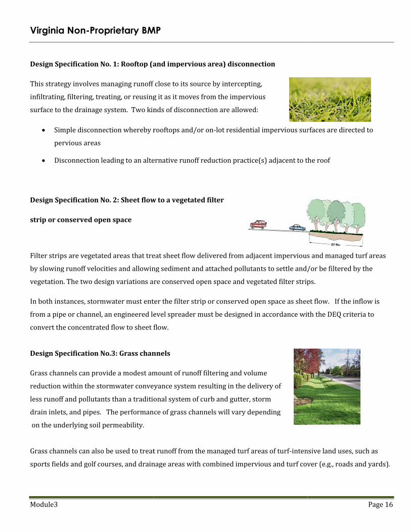
Design Specification No.3: Grass channels
Grass channels can provide a modest amount of runoff filtering and volume
reduction within the stormwater conveyance system resulting in the delivery of
less runoff and pollutants than a traditional system of curb and gutter, storm
drain inlets, and pipes. The performance of grass channels will vary depending
on the underlying soil permeability.
Grass channels can also be used to treat runoff from the managed turf areas of turf
sports fields and golf courses, and drainag
Proprietary BMP
Rooftop (and impervious area) disconnection
This strategy involves managing runoff close to its source by intercepting,
infiltrating, filtering, treating, or reusing it as it moves from the impervious
Two kinds of disconnection are allowed:
Simple disconnection whereby rooftops and/or on-lot residential impervious surfaces are directed to
Disconnection leading to an alternative runoff reduction practice(s) adjacent to the roof
Sheet flow to a vegetated filter
Filter strips are vegetated areas that treat sheet flow delivered from adjacent impervious and managed turf areas
by slowing runoff velocities and allowing sediment and attached pollutants to settle and/or be filtered by the
are conserved open space and vegetated filter strips
In both instances, stormwater must enter the filter strip or conserved open space as sheet flow.
ipe or channel, an engineered level spreader must be designed in accordance with the DEQ criteria to
convert the concentrated flow to sheet flow.
Grass channels
Grass channels can provide a modest amount of runoff filtering and volume
reduction within the stormwater conveyance system resulting in the delivery of
less runoff and pollutants than a traditional system of curb and gutter, storm
The performance of grass channels will vary depending
Grass channels can also be used to treat runoff from the managed turf areas of turf-intensive land uses, such as
sports fields and golf courses, and drainage areas with combined impervious and turf cover (e.g., roads and yards).
Page 16
lot residential impervious surfaces are directed to
Disconnection leading to an alternative runoff reduction practice(s) adjacent to the roof
Filter strips are vegetated areas that treat sheet flow delivered from adjacent impervious and managed turf areas
ts to settle and/or be filtered by the
vegetated filter strips.
In both instances, stormwater must enter the filter strip or conserved open space as sheet flow. If the inflow is
ipe or channel, an engineered level spreader must be designed in accordance with the DEQ criteria to
intensive land uses, such as
e areas with combined impervious and turf cover (e.g., roads and yards).

Module3 Page 17
Design Specification No. 4: Soil compost amendments
Soil restoration is an Environmental Site Design (ESD) practice
applied after construction to deeply till compacted soils and restore
their porosity by amending them with compost. These soil
amendments can reduce the generation of runoff from compacted
urban lawns and may also be used to enhance the runoff reduction
performance of downspout disconnections, grass channels, and filter strips.
Design Specification No. 5: Vegetated roofs
Vegetated roofs are alternative roof surfaces that typically consist of
waterproofing and drainage materials and an engineered growing
media that is designed to support plant growth. Vegetated roofs
capture and temporarily store stormwater runoff in the growing
media before it is conveyed into the storm drain system. A portion of
the captured stormwater evaporates or is taken up by plants, which helps reduce runoff volumes, peak runoff
rates, and pollutant loads on development sites.
There are two different types of vegetated roof systems. The first, intensive vegetated roofs have a
deeper growing media layer that ranges from 6 inches to 4 feet thick, which is planted with a wider
variety of plants, including trees. The second, extensive systems typically have much shallower growing
media (2 to 6 inches), which is planted with carefully selected drought tolerant vegetation. Extensive
vegetated roofs are much lighter and less expensive than intensive vegetated roofs and are recommended
for use on most development and redevelopment sites.
Design Specification No. 6: Rainwater harvesting
Rainwater harvesting systems intercept, divert, store, and release rainfall for
future use. The term rainwater harvesting is used in this specification, but it
is also known as a cistern or rainwater harvesting system. Rainwater that
falls on a rooftop is collected and conveyed into an above- or below-ground
storage tank where it can be used for non-potable water uses and on-site
stormwater disposal/infiltration. Non-potable uses may include flushing of
toilets and urinals inside buildings, landscape irrigation, exterior washing (e.g. car washes, building facades,
sidewalks, street sweepers, fire trucks, etc.), and fire suppression (sprinkler) systems.

Module3 Page 18
In many instances, rainwater harvesting can be combined with a secondary (down-gradient) runoff reduction
practice to enhance runoff volume reduction rates and/or provide treatment of overflow from the rainwater
harvesting system.
Design Specification No. 7: Permeable pavement
Permeable pavements are alternative paving surfaces that allow
stormwater runoff to filter through voids in the pavement surface into an
underlying stone reservoir, where it is temporarily stored and/or
infiltrated. A variety of permeable pavement surfaces are available,
including pervious concrete, porous asphalt, and permeable
interlocking concrete pavers. While the specific design may vary, all
permeable pavements have a similar structure, consisting of a surface pavement layer, an underlying stone
aggregate
reservoir layer and a filter layer or fabric installed on the bottom.
Design Specification No. 8: Infiltration
Infiltration practices use temporary surface or underground storage to allow incoming stormwater runoff to go
into underlying soils. Runoff first passes through multiple pretreatment mechanisms to trap sediment and organic
matter before it reaches the practice. As the stormwater penetrates the underlying soil, chemical and physical
adsorption processes remove pollutants. Infiltration practices have the greatest runoff reduction capability of any
stormwater practice and are suitable for
use in residential and other urban areas
where measured soil permeability rates
exceed 1/2 inch per hour. To prevent
possible groundwater contamination,
infiltration should not be utilized at sites
designated
as stormwater hotspots.
Design Specification No. 9: Bioretention Basins
Individual bioretention areas can serve highly impervious drainage areas less
than two acres in size. Surface runoff is directed into a shallow
landscaped depression that incorporates many of the pollutant removal
mechanisms that operate in forested ecosystems. The primary

Module3
component of a bioretention practice is the filter bed, which has a mixture of sand, soil, and organic material
filtering media with a surface mulch layer.
mulch layer and then rapidly filters through the bed.
and returned to the storm drain system.
along the bottom of the filter bed. A bioretention facility
bioretention filter. A bioretention facility
commonly referred to as a bioretention
lot is commonly referred to as a rain garden
Design Specification No. 10: Dry swales
Dry swales are essentially bioretention cells that are shallower,
configured as linear channels, and covered with turf or other surface
material (other than mulch and ornamental plants).
system that temporarily stores and then filters the desired t
volume (Tv). Dry swales rely on a pre-mixed soil media filter below the
channel that is similar to that used for bioretention.
underlying soils. In most cases, however, the runoff treated by the soil media flows into an underdrain,
conveys treated runoff back to the conveyance system fu
perforated pipe within a gravel layer on the bottom of the swale,
as simple grass channels with the same shape
Swales can be planted with turf grass, tall meadow grasses, decorative herbaceous cover, or trees.
Design Specification No. 11: Wet swales
Wet swales can provide runoff filtering and treatment within the
conveyance system and are a cross between a wetland and a swale.
These linear wetland cells often intercept shallow
maintain a wetland plant community. The saturated soil and wetland
vegetation provide an ideal environment for gravitational settling,
biological uptake, and microbial activity.
formed within the channel to create saturated soil or shallow
water conditions (typically less than 6 inches deep).
of a bioretention practice is the filter bed, which has a mixture of sand, soil, and organic material
filtering media with a surface mulch layer. During storms, runoff temporarily ponds 6 to
through the bed. Normally, the filtered runoff is collected in an underdrain
and returned to the storm drain system. The underdrain consists of a perforated pipe in a gravel layer installed
bioretention facility with an underdrain system is commonly referred to as a
A bioretention facility without an underdrain system or with a storage sump in the bottom is
ioretention basin. Small-scale or micro-bioretention used on an individual residential
arden.
Design Specification No. 10: Dry swales
Dry swales are essentially bioretention cells that are shallower,
and covered with turf or other surface
material (other than mulch and ornamental plants). They are a soil filter
s and then filters the desired treatment
mixed soil media filter below the
to that used for bioretention. If soils are extremely permeable, runoff infiltrates into
soils. In most cases, however, the runoff treated by the soil media flows into an underdrain,
conveys treated runoff back to the conveyance system further downstream. The underdrain system consists of a
perforated pipe within a gravel layer on the bottom of the swale, beneath the filter media.
as simple grass channels with the same shape and turf cover, while others may have more elaborate landscaping.
turf grass, tall meadow grasses, decorative herbaceous cover, or trees.
Design Specification No. 11: Wet swales
Wet swales can provide runoff filtering and treatment within the
cross between a wetland and a swale.
These linear wetland cells often intercept shallow groundwater to
The saturated soil and wetland
provide an ideal environment for gravitational settling,
uptake, and microbial activity. On-line or off-line cells are
formed within the channel to create saturated soil or shallow standing
water conditions (typically less than 6 inches deep).
Page 19
of a bioretention practice is the filter bed, which has a mixture of sand, soil, and organic material as the
During storms, runoff temporarily ponds 6 to 12 inches above the
runoff is collected in an underdrain
consists of a perforated pipe in a gravel layer installed
with an underdrain system is commonly referred to as a
without an underdrain system or with a storage sump in the bottom is
ed on an individual residential
If soils are extremely permeable, runoff infiltrates into
soils. In most cases, however, the runoff treated by the soil media flows into an underdrain, which
underdrain system consists of a
beneath the filter media. Dry swales may appear
more elaborate landscaping.
turf grass, tall meadow grasses, decorative herbaceous cover, or trees.

Module3
Design Specification No. 12: Filtering practices
Stormwater filters are a useful practice to treat stormwater runoff
small, highly impervious sites. Stormwater filters capture, temporarily
store, and treat stormwater runoff by passing it
filter media, collecting the filtered water in an und
returning it back to the storm drainage system. The filter consists of two chambers: the first is
and the second serves as a filter bed consisting of
Design Specification No. 13: Constructed wetlands
Constructed wetlands, sometimes called stormwater wetlands, are shallow
depressions that receive stormwater inputs for water quality treatment.
Wetlands are typically less than one-foot
depths at the forebay and in micropools) and possess variable
microtopography to promote dense and diverse wetland cover.
from each new storm displaces runoff from previous storms, and the long
residence time allows multiple pollutant removal processes to operate. The w
environment for gravitational settling, biological uptake, and microbial activity.
element in the roof-to-stream runoff reduction sequence.
upland runoff reduction opportunities have been exhausted
protection volume to manage.
Design Specification No. 14: Wet pond
Wet ponds consist of a permanent pool of standing water that
settling, biological uptake, and microbial activity.
displaces pool water from previous storms.
pollutants deposited during prior storms. When
wet ponds have a residence time that ranges from many days to
several weeks, which allows numerous pollutant removal
mechanisms to operate. Wet ponds can also provide
detention above the permanent pool to help meet channel
protection requirements.
Design Specification No. 12: Filtering practices
tice to treat stormwater runoff from
Stormwater filters capture, temporarily
store, and treat stormwater runoff by passing it through an engineered
filter media, collecting the filtered water in an underdrain, and then
returning it back to the storm drainage system. The filter consists of two chambers: the first is
s as a filter bed consisting of sand or organic filter media.
ucted wetlands
Constructed wetlands, sometimes called stormwater wetlands, are shallow
receive stormwater inputs for water quality treatment.
foot deep (although they have greater
and in micropools) and possess variable
microtopography to promote dense and diverse wetland cover. Runoff
new storm displaces runoff from previous storms, and the long
pollutant removal processes to operate. The wetland environment provides an ideal
for gravitational settling, biological uptake, and microbial activity. Constructed wetlands are the
stream runoff reduction sequence. They should only be considered
upland runoff reduction opportunities have been exhausted and there is still a remaining water quality or channel
Design Specification No. 14: Wet pond
Wet ponds consist of a permanent pool of standing water that promotes a better environment for
and microbial activity. Runoff from each new storm enters the pond and partially
displaces pool water from previous storms. The pool also acts as a barrier to re-suspension of
pollutants deposited during prior storms. When sized properly,
wet ponds have a residence time that ranges from many days to
which allows numerous pollutant removal
Wet ponds can also provide extended
detention above the permanent pool to help meet channel
Page 20
returning it back to the storm drainage system. The filter consists of two chambers: the first is devoted to settling,
etland environment provides an ideal
Constructed wetlands are the final
They should only be considered for use after all other
and there is still a remaining water quality or channel
promotes a better environment for gravitational
enters the pond and partially
suspension of sediments and other

Module3 Page 21
Design Specification No. 15: Extended detention (ED) pond
An Extended Detention (ED) Pond relies on 12 to 24 hour detention of stormwater runoff after each rain event. An
under-sized outlet structure restricts stormwater flow so it backs up and is stored within the basin. The temporary
ponding enables particulate pollutants to settle out and reduces the maximum peak discharge to the downstream
channel, thereby reducing the effective shear stress on banks of the receiving stream.
ED is normally combined with wet ponds (Design Specification No 14) or constructed wetlands (Design
Specification No 13) to maximize pollutant removal rates. Designers should note that an ED pond is the final
element in the roof to stream runoff reduction sequence, so one should be considered only if there is remaining
treatment volume or channel protection volume to manage after all other upland runoff reduction practices have
been considered and properly credited. Designers may need to submit documentation to the local plan review
authority showing that all other runoff reduction opportunities have
been exhausted and were found to be insufficient, leaving additional
water quality or channel protection volume to manage.

Module3 Page 22
When these stormwater BMP’s are being (or have been constructed), sediment is enemy. In order to ensure
the enemy is kept at bay, the responsible land disturber/contractor can do thing so as the following:
Perform maintenance on ESC practices as per the VESCP; Minimize the soils which will be compacted or disturbed; Install each BMP as per the approved plan; Follow the established construction sequence; Coordinate installation with the professional engineer.
The above is just a sampling of what module 4 will detail.
Practice Number BMP Practice
1 Rooftop disconnection
2 Sheet flow to vegetated filter or conserved open space 1
3 Grass channel
4 Soil amendments
5 Vegetated roof
6 Rainwater harvesting
7 Permeable pavement
8 Infiltration
9 Bioretention
10 Dry swale
11 Wet swale
12 Filtering practice
13 Constructed wetland
14 Wet pond
15 Extended detention pond