Embed Size (px)
Citation preview
Nitriding
UN
IVE
RS
ITY
OF T
RE
NT
O
Prof. M. Pellizzari
Course
Metallic Materials Engineering
Module 2

Nitriding M. Pellizzari Metallic Materials Engineering, - Module II
Summary
Fe-N equilibrium diagram
Nitriding processes • Gas nitriding
Lehrer diagram, Nitrogen potential KN
N. paramaters: time, temperature, KN
N. atmosphere
• Plasma nitriding
Microstrucure of nitrided steel Diffusion layer, compound layer
Nitridability
Nitriding steels
Nitriding
Nitriding M. Pellizzari Metallic Materials Engineering, - Module II
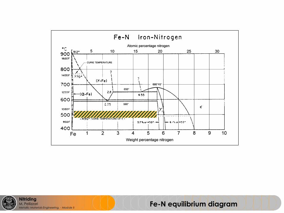
Fe-N equilibrium diagram

Nitriding M. Pellizzari Metallic Materials Engineering, - Module II
Lehrer diagram
2/33
2/13333
2/32
3
)(5.1
)()()()(
)(
)(
disso
dissoodissoo
R
RN
NH
NHNHNHNH
H
NHK
Nitrogen potential
Ammonia dissociation
2NH3(gas) 2N + 3H2(gas)
Gas nitriding

Nitriding M. Pellizzari Metallic Materials Engineering, - Module II
Compound layer
(white layer)
Diffusion layer
Thickness
Composition
Constitution
Porosity
Depth
(Deff., Dtot)
Hardness
(Microh. profile)
Internal stresses
Performance!
Processing parameters
Unnitrided core
Material
Nitriding Base material – processing parameters - performance

Nitriding M. Pellizzari Metallic Materials Engineering, - Module II
depth from surface
MICROHARDNESS
PROFILE
Diffusion layer
HV0.1 550HV
S.E.
Stot
• Solid solution hardening(N)
• Precipitation hardening (nitrides)
Diffusion layer: hardening mechanisms

Nitriding M. Pellizzari Metallic Materials Engineering, - Module II
Nitrides precipitation
porosity
Fe2,3N
Grain boundary
carbonitrides
Fe4N

Nitriding M. Pellizzari Metallic Materials Engineering, - Module II
Residual stresses

Nitriding M. Pellizzari Metallic Materials Engineering, - Module II
10 m
porosity
%N
Compound layer
Diffusion layer
Fe 4 N
Fe 2,3 N
Grain boundary carbonitrides
7.8 - 11.3 %wt
5.7 - 6.1 %wt
Nitride N solub. limit
[%wt]
C solub. limit
[%wt]
Fe4N fcc 5.7- 6.1 <0.2
Fe2,3N hcp 7.8-11.3 <4
Compound layer
Fe4N

Nitriding M. Pellizzari Metallic Materials Engineering, - Module II
223
2
3
2
1HNNH
NN 2
2
1
23
2
3HNNH
aN = K(T) · KN
Gas nitriding Nitrogen activity aN and nitriding potential KN
2/33
2/13333
2/32
3
)(5.1
)()()()(
)(
)(
disso
dissoodissoo
R
RN
NH
NHNHNHNH
H
NHK
Nitriding potential: KN

Nitriding M. Pellizzari Metallic Materials Engineering, - Module II
Lehrer Diagram
Lehrer diagram
Local equilibrium at
worpiece surface !
No information about
process kinetiks !
No information about
The effect of C !

Nitriding M. Pellizzari Metallic Materials Engineering, - Module II
KN = 0.3
KN = 1.0
KN = 2.5
KN = 0.5
Nitriding Potential KN
0.5h 1h 2h 5h 10h 20h 30h 40h
Nitriding time
Nitriding
potential Normalized C45

Nitriding M. Pellizzari Metallic Materials Engineering, - Module II
Compound layer thickness = f (T, t, KN)
Nitriding time, t Co
mp
ou
nd
la
ye
r t
hic
kn
ess
, S
c.l
.
])(
1[02
401..
NN KKaettaS lc

Nitriding M. Pellizzari Metallic Materials Engineering, - Module II
wt% N wt% N
wt% C wt% C
Depth from surface Depth from surface
Compound layer composition

Nitriding M. Pellizzari Metallic Materials Engineering, - Module II
Diffusion layer thickness = f(T,t)
c = 0.2 [mm/h1/3]
t = nitriding time [h]
Nitriding time, t
Diffu
sio
n la
ye
r t
hic
kn
ess
, D
N
tcDN 3

Nitriding M. Pellizzari Metallic Materials Engineering, - Module II
DN = k • t1/2
DN = case depth
k = k(T)
t = time [h]
Effect of nitrding time and temperature

Nitriding M. Pellizzari Metallic Materials Engineering, - Module II
Nitridability

Nitriding M. Pellizzari Metallic Materials Engineering, - Module II
Oxigen probe
Relationship between the reactions of O2 and the nitriding reactions.
Possibilty to control the nitriding process through pO2 (O2 partial pressure)
)2
31log(0992.0 ETUE E
Fresh inlet gas Composition
2/32
3
)(
)(
H
NHK
R
RN
)(
)(
2
2
H
OHK
R
RO
Nitriding atmosphere Catalytic dissociator
Zirconia element

Nitriding M. Pellizzari Metallic Materials Engineering, - Module II
Nitriding by variable KN
Nitriding time
Co
mp
ou
nd
la
ye
r t
hic
kn
ess
A certain compound layer
thickness can be obtained
independently from diffusion
layer thickness (nitrided case
depth)!

Nitriding M. Pellizzari Metallic Materials Engineering, - Module II
Nitrding steels UNI EN 10085 2003
Quench and tempering steels
Low alloyed tool steels: (NiCrMo)
High alloyed tool steels
Hot work tool steels
High speed steels

Nitriding M. Pellizzari Metallic Materials Engineering, - Module II
Nitrding steels UNI EN 10085 2003

Nitriding M. Pellizzari Metallic Materials Engineering, - Module II
Nitrding steels UNI EN 10085 2003

Nitriding M. Pellizzari Metallic Materials Engineering, - Module II
Gas nitriding furnace

Nitriding M. Pellizzari Metallic Materials Engineering, - Module II
Plasma nitriding

Nitriding M. Pellizzari Metallic Materials Engineering, - Module II
Fe4N
Fe4N
Fe2N
FeN
FeN
Fe
Cathode (-)
STEEL
Anode (+)
N°
N
N
N
Plasma nitriding

Nitriding M. Pellizzari Metallic Materials Engineering, - Module II
Advantages of plasma nitriding
- Optimum control of N transfer at the workpiece surface
- Control of compound layer constitution (, ’)
- Possibility of avoiding compound layer formation
- Control/Elimination of porosity in the compound layer
- Better control of nitrided case depth
- Lower amount of grain boundary carbonitrides
- Lower process temperatures
- Lower distorsions
- Minimal wastes (no ammonia)
- Low energy consumption
- Automatic process
- Selective nitriding trough electrical masking
- Materials: PM materials, stainless steel…
Disvantages of plasma nitriding
- Limited size of treated parts (cold wall furnaces)
- Limited productivity
- Difficult by components with high volume/surface area ratio
- Edge effect
- Low penetrating power in cavities, holes…
Plasma nitriding

Nitriding M. Pellizzari Metallic Materials Engineering, - Module II
• Increased surface hardness
• Increased wear resistance
• Improved fatigue resistance
• Improved thermal stability
Benefits of nitriding

Nitriding M. Pellizzari Metallic Materials Engineering, - Module II
0 200 400 600 800 1000
200
400
600
800
1000
1200
GNH
GNL
GNC
IN
INCL
INCH
HV
0.2
distanza dalla superficie [m]
10 m GNH 20 m
20 m 10 m
10 m 10 m
GNL
GNC IN
INCH INCL
Nitrided steel - microstructure

Nitriding M. Pellizzari Metallic Materials Engineering, - Module II
A7 A6 A5 A4 A3 A2 A10
2
4
6
8
10
G
GGGI
I
I
--------- % Carbonitruri a bordograno -------->
Tasso d
i usura
(g
/rev x
E-6
)
I = plasma
G = gas
500 N
1000 N
2000 N
50m 50m
Molinari, G. Straffelini, M. Pellizzari, M. Pirovano: Surface Engineering, 1998 Vol.14 No.6., 489
Nitrided steel – extrusion screw

Nitriding M. Pellizzari Metallic Materials Engineering, - Module II
Curve di usura per l'acciaio EN40B nitrurato, rivestito con
TiN e nitrurato+TiN (trattamento duplex)
“Load bearing capability”
Duplex treatment es: Nitriding+PVD
Nitrided – duplex PVD coated steel

Nitriding M. Pellizzari Metallic Materials Engineering, - Module II
Die casting dies

Nitriding M. Pellizzari Metallic Materials Engineering, - Module II
0 100 200 300 400 500 600
0
100
200
300
400
500
600
N
NCZ
NC
NZ
CZ NO
P max =
d tot
100 cicli a Tmax
= 900°C
120 cicli a Tmax
= 700°C
Pm
ax [
m]
dtot
[m]
50 m
Pmax dtot
nitriding vs. duplex-PVD coatings
Die casting dies
Thermal fatigue resistance
Maximum crack crack length vs. total case depth

Nitriding M. Pellizzari Metallic Materials Engineering, - Module II
10 m
10 m 10 m
10 m 20 m
10 m
Inductor
Pyrometer
Cooling water
Sample
Water nozzle
50 m
M. Pellizzari, A. Molinari, G. Straffelini: To be published in Mat.Sci.Eng.
Die casting dies
Gas nitriding vs. plasma nitriding
Thermal fatigue resistance

Nitriding M. Pellizzari Metallic Materials Engineering, - Module II
Compound layer
INERT
Diffusion layer
REACTIVE
Unnitrided steel core
INERT
Chemical rectivity against Nital 2%
(2%vol Nitric acid + 98% Etilico alcool)
Plastic mould dies
Corrosion resistance

Nitriding M. Pellizzari Metallic Materials Engineering, - Module II
Nitrocarburizing
• As in nitriding (N) also in nitrocarburizing (NC) the main element transferred to
the steel is nitrogen but in addition also carbon.
• NC gives the principal surface microstructure and hardness of N
• Nitrocarburizing started to grow remarkably with the development of the salt bath
process Tenifer (Tufftride) and the gaseous process Nitemper developed in the
sixties.
• Compared to classical nitriding, nitrocarburizing is a short time process, typically
30 minutes to 4 hours, performed at higher temperature, about 570°C compared
to 500–510 °C for gas nitriding.
• Normally both phases coexist but γ' is dominating after nitriding and ε after
nitrocarburizing. The γ'-phase causes brittle compound layers whereas ε has a
higher ductility.
• The goal of NC is a monophase ε-compound layer. Good frictional porperties are
attributed to this iron nitride, having an HCP cristral structure, similar to graphite
(good solid lubricant).
• The outermost part of the compound layer normally has some porosity.
(beneficial to lubricant entrapment and deliver during poor lubricity service
conditions).

Nitriding M. Pellizzari Metallic Materials Engineering, - Module II
• A remarkable improvement in corrosion resistance is obtained if
nitrocarburizing is followed by a short oxidation at about 450 °C.
• A 1– 2 µm thick Fe3O4 (magnetite, HCP) layer is formed on top of the
compound layer.
• The oxidation treatment gives the processed parts an aesthetically
attractive black colour.
• The first gaseous process was developed by Lucas, England, and is
called Nitrotec = Nitemper process + oxidation treatment in air. Other
oxidation methods using for example water vapour or nitrous oxide
(N2O) have later on been used.
Nitrocarburizing + postoxidation

Nitriding M. Pellizzari Metallic Materials Engineering, - Module II
Nitriding vs. Nitrocarburizing
• Three groups related to the
process medium, which may be
salt, gas or plasma.
• The salt bath processes are
loosing market to the gas
processes due to the
environmental problems with
salts, containing cyanide.
• Plasma processes are still used
in a limited number of cases but
the use increases because of
specific advantages such as the
possibility to use very low
process temperature and to
nitride e.g. stainless steel, which
is difficult by other methods.
FURNACE ATMOSPHERES 3 Nitriding and Nitrocarburizing by Torsten Holm, Lars Sproge

Nitriding M. Pellizzari Metallic Materials Engineering, - Module II
Nitriding vs. carburizing
from “Surface Hardening of Steel – Understanding the basics”, Edited by J.R. Davis, ASM International, 2002, p.3