Embed Size (px)
Citation preview
APPLIED GEOTECHNICAL ENGINEERING 15CV53
ATME College of Engineering Page 1
MODULE 1
SOIL EXPLORATION
1. INTRODUCTION
1.1 OBJECTIVES AND IMPORTANCE
1.2 STAGES OF EXPLORATION
1.3 METHODS OF EXPLORATION
1.3.1 DIRECT METHOD
TRIAL PITS
1.3.2 SEMIDIRECT METHOD
AUGER BORING
WASH BORING
PERCUSSION BORING
ROTARY BORING
1.3.3 INDIRECT METHOD
1.3.3.1 STANDARD PENETRATION TEST
1.3.3.2 GEOPHYSICAL METHODS
SEISMIC REFRACTION METHOD
ELECTRICAL RESISTIVITY METHOD
1.4 TYPES OF SAMPLES
UNDISTURBED SOIL SAMPLE
DISTURBED SOIL SAMPLE
1.5 SAMPLING TECHNIQUES/ SOIL SAMPLERS
SPLIT SPOON SAMPLERS
PISTON SAMPLERS
ROTARY SAMPLERS
1.6 SAMPLE DISTURBANCE
1.7 STABILIZATION OF BOREHOLES
1.8 BORE LOG.
1.9 ESTIMATION OF DEPTH OF GWT (HVORSLEV’S METHOD)
1.10 DRAINAGE AND DEWATERING METHODS.
1.11 RECOMMENDED QUESTIONS
1.12 OUTCOMES
1.13 FURTHER READING
APPLIED GEOTECHNICAL ENGINEERING 15CV53
ATME College of Engineering Page 2
1. INTRODUCTION
A fairly accurate assessment of the characteristics and engineering properties of the soils at a
site is essential for proper design and successful construction of any structure at the site. The
field and laboratory investigations required to obtain the necessary data for the soils for this
purpose are collectively called soil exploration.
The choice of the foundation and its depth, the bearing capacity, settlement analysis & such
other important aspects depend very much upon the various engineering properties of the
foundation soils involved.
Soil exploration may be needed not only for the design and construction of new structures,
but also for deciding upon remedial measures if a structure shows signs of distress after
construction. The design and construction of highway and airport pavements will also depend
upon the characteristics of the soil strata upon which they are to be aligned.
1.1 OBJECTIVES OR IMPORTANCE OF SOIL EXPLORATION
(i) Determination of the nature of the deposits of soil,
(ii) Determination of the depth and thickness of the various soil strata and their extent in
horizontal direction,
(iii) The location of groundwater and fluctuations in Ground Water Table,
(iv) Obtaining soil and rock samples from the various strata,
(v) The determination of the engineering properties of the soil and rock strata that affect the
Performance of the structure, and
(vi) Determination of the in-situ properties by performing field tests.
The different methods to know the different strata of the soil is called as methods of
exploration
1.2 STAGES IN SOIL EXPLORATION
STAGE 1: RECONNAISSANCE
This may be in the form of a field trip to the site which can reveal information on the type
and behavior of adjacent sites and structures such as cracks, noticeable sags, and possibly
sticking doors and windows. The type of local existing structure may influence, to a
considerable extent, the exploration program and the best foundation type for the proposed
adjacent structure. Since nearby existing structures must be maintained, excavations or
vibrations will have to be carefully controlled. Erosion in existing cuts (or ditches) may also
APPLIED GEOTECHNICAL ENGINEERING 15CV53
ATME College of Engineering Page 3
be observed. For highways, run off patterns, as well as soil stratification to the depth of the
erosion cut, may be observed. Rocky outcrops may give an indication of the presence or the
depth of bedrock.
STAGE 2: PRELIMINARY EXPLORATION
In this phase a few borings are made or a test pit is opened to establish in a general manner
the stratification, types of soil to be expected, and possibly the location of the groundwater
table. One or more borings should be taken to rock, or competent strata, if the initial borings
indicate the upper soil is loose or highly compressible. This amount of soil exploration is
usually the extent of the site investigation for small structures. A feasibility exploration
program should include enough site data and sample recovery to approximately establish the
foundation design and identify the construction procedures. It is common at this stage to limit
the number of good quality samples recovered and rely heavily on strength and settlement
correlations using index properties such as liquid limit, plasticity index, and penetration data
together with unconfined compression tests on samples recovered during penetration testing.
STAGE 3: DETAILED EXPLORATION
Where the preliminary site investigation has established the feasibility of the project, a more
detailed exploration program is undertaken. The preliminary borings and data are used as a
basis for locating additional borings, which should be confirmatory in nature, and
determining the additional samples required. If the soil is relatively uniform in stratification,
a rather orderly spacing of borings at locations close to critical superstructure elements
should be made. On occasion additional borings will be required to delineate zones of poor
soil, rocky outcrops, fills, and other areas which can influence the design and construction of
the foundation. Sufficient additional samples should be recovered to redefine the design and
for any construction procedure required by the contractor to install the foundation. This
should avoid an excessive bid for the foundation work, cost overruns, and damage to adjacent
property owners from unanticipated soil conditions discovered when the excavation is
opened.
1.3 METHODS OF EXPLORATIONS
Direct method
Semi direct method
Indirect method
APPLIED GEOTECHNICAL ENGINEERING 15CV53
ATME College of Engineering Page 4
1.3.1 DIRECT METHOD
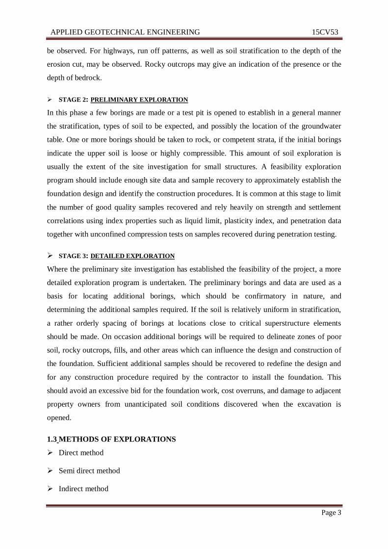
TRIAL PITS
Applicable to all types of soils Provide for visual examination in their natural condition.
Disturbed and undisturbed soil samples can be conveniently obtained at different depths.
Depth of investigation is limited to 3 to 3.5 m.
Advantages
i) Cost effective.
ii) Provide detailed information of stratigraphy.
iii) Large quantities of disturbed soils are available for testing.
iv) Large blocks of undisturbed samples can be carved out from the pits.
v) Field tests can be conducted at the bottom of the pits.
Disadvantages
i) Depth limited to about 6m.
ii) Deep pits uneconomical.
iii) Excavation below groundwater and into rock difficult and costly.
iv) Too many pits may scar site and require backfill soils.
Limitations
i) Undisturbed sampling is difficult
ii) Collapse in granular soils or below ground water table
APPLIED GEOTECHNICAL ENGINEERING 15CV53
ATME College of Engineering Page 5
1.3.2 SEMI DIRECT METHOD:
BORING TECHNIQUES
Making or drilling bore holes into the ground with a view to obtaining soil or rock samples
from specified or known depths is called ‘boring’.
The common methods of advancing bore holes are:
1. Auger boring
2. Auger and shell boring
3. Wash boring
4. Percussion drilling
5. Rotary drilling
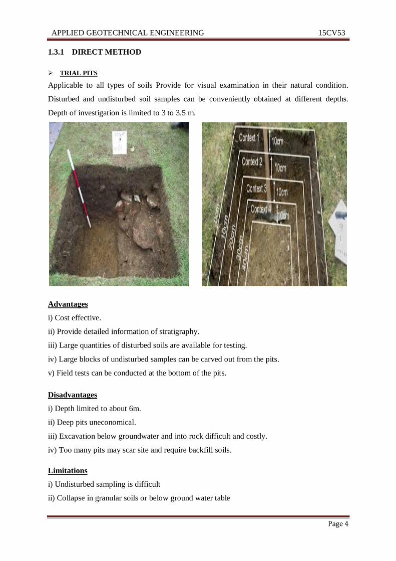
AUGER BORING
‘Soil auger’ is a device that is useful for advancing a bore hole into the ground. Augers may
be hand-operated or power-driven; the former are used for relatively small depths (less than 7
m), while the latter are used for greater depths. The soil auger is advanced by rotating it while
pressing it into the soil at the same time. It is used primarily in soils in which the bore hole
can be kept dry and unsupported. As soon as the auger gets filled with soil, it is taken out and
the soil sample collected. Two common types of augers, the post hole auger and the helical
auger.

APPLIED GEOTECHNICAL ENGINEERING 15CV53
ATME College of Engineering Page 6
AUGER AND SHELL BORING
If the sides of the hole cannot remain unsupported (filled soils), then the soil presented
besides should be prevented from sliding in by means of a pipe known as ‘shell’ or ‘casing’.
The casing is to be driven first and then the auger; whenever the casing is to be extended, the
auger has to be withdrawn, this being an impediment to quick progress of the work. An
equipment called a ‘boring rig’ is employed for power-driven augers, which may be used up
to 50 m depth (A hand rig may be sufficient for borings up to 25 m in depth). Casings may be
used for sands or stiff clays. Soft rock or gravel can be broken by chisel bits attached to drill
rods. Sand pumps are used in the case of sandy soils.
WASH BORING
Wash boring is commonly used for exploration below ground water table for which the auger
method is unsuitable. This method may be used in all kinds of soils except those mixed with
gravel and boulders. The set-up for wash boring is shown in Fig.
Initially, the hole is advanced for a short depth by using an auger. A casing pipe is pushed in
and driven with a drop weight. The driving may be with the aid of power. A hollow drill bit is
screwed to a hollow drill rod connected to a rope passing over a pulley and supported by a
tripod. Water jet under pressure is forced through the rod and the bit into the hole.
APPLIED GEOTECHNICAL ENGINEERING 15CV53
ATME College of Engineering Page 7
This loosens the soil at the lower end and forces the soil-water suspension upwards along the
annular surface between the rod and the side of the hole. This suspension is led to a settling
tank where the soil particles settle while the water overflows into a sump. The water collected
in the sump is used for circulation again.
The soil particles collected represent a very disturbed sample and is not very useful for the
evaluation of the engineering properties. Wash borings are primarily used for advancing bore
holes; whenever a soil sample is required, the chopping bit is to be replaced by a sampler.
The change of the rate of progress and change of color of wash water indicate changes in soil
strata.
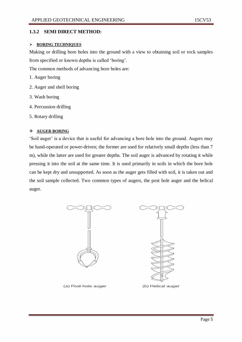
PERCUSSION DRILLING
A heavy drill bit called ‘churn bit’ is suspended from a drill rod or a cable and is driven by
repeated blows. Water is added to facilitate the breaking of stiff soil or rock. The slurry of the
pulverized material is bailed out at intervals. The method cannot be used in loose sand and is
slow in plastic clay. The formation gets badly disturbed by impact.
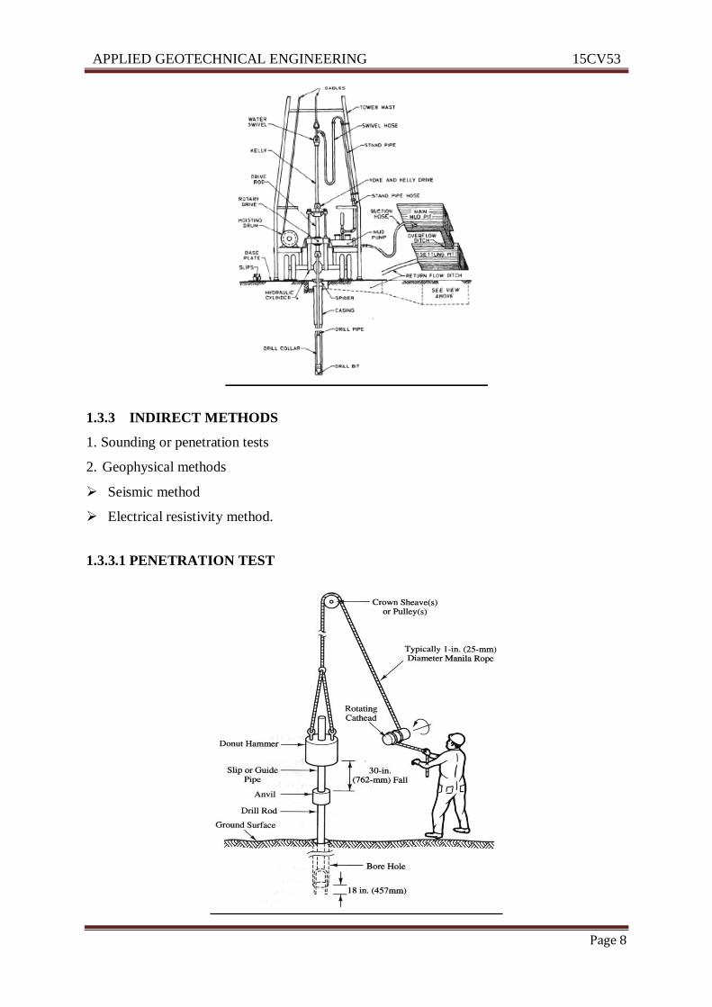
ROTARY DRILLING
This method is fast in rock formations. A drill bit, fixed to the lower end of a drill rod, is
rotated by power while being kept in firm contact with the hole. Drilling fluid or bentonite
slurry is forced under pressure through the drill rod and it comes up bringing the cuttings to
the surface. Even rock cores may be obtained by using suitable diamond drill bits. This
method is not used in porous deposits as the consumption of drilling fluid would be
prohibitively high.
APPLIED GEOTECHNICAL ENGINEERING 15CV53
ATME College of Engineering Page 8
1.3.3 INDIRECT METHODS
1. Sounding or penetration tests
2. Geophysical methods
Seismic method
Electrical resistivity method.
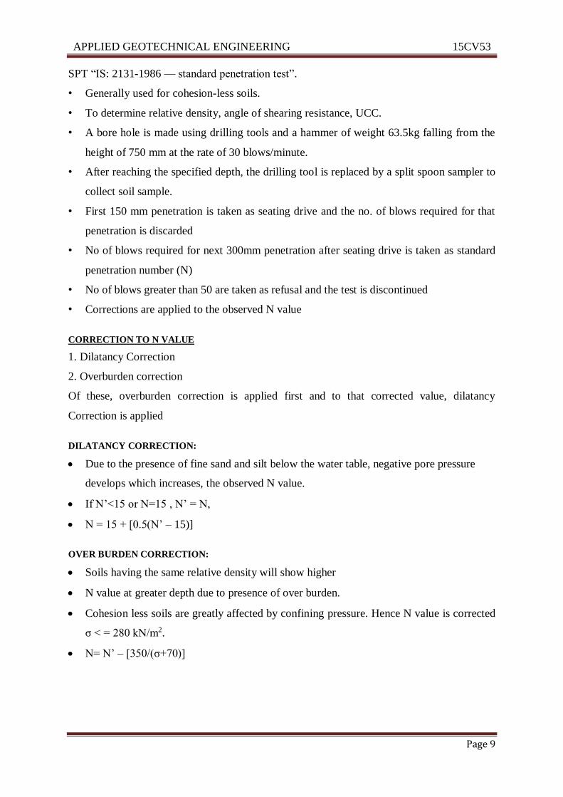
1.3.3.1 PENETRATION TEST
APPLIED GEOTECHNICAL ENGINEERING 15CV53
ATME College of Engineering Page 9
SPT “IS: 2131-1986 — standard penetration test”.
• Generally used for cohesion-less soils.
• To determine relative density, angle of shearing resistance, UCC.
• A bore hole is made using drilling tools and a hammer of weight 63.5kg falling from the
height of 750 mm at the rate of 30 blows/minute.
• After reaching the specified depth, the drilling tool is replaced by a split spoon sampler to
collect soil sample.
• First 150 mm penetration is taken as seating drive and the no. of blows required for that
penetration is discarded
• No of blows required for next 300mm penetration after seating drive is taken as standard
penetration number (N)
• No of blows greater than 50 are taken as refusal and the test is discontinued
• Corrections are applied to the observed N value
CORRECTION TO N VALUE
1. Dilatancy Correction
2. Overburden correction
Of these, overburden correction is applied first and to that corrected value, dilatancy
Correction is applied
DILATANCY CORRECTION:
Due to the presence of fine sand and silt below the water table, negative pore pressure
develops which increases, the observed N value.
If N’<15 or N=15 , N’ = N,
N = 15 + [0.5(N’ – 15)]
OVER BURDEN CORRECTION:
Soils having the same relative density will show higher
N value at greater depth due to presence of over burden.
Cohesion less soils are greatly affected by confining pressure. Hence N value is corrected
σ < = 280 kN/m2.
N= N’ – [350/(σ+70)]
APPLIED GEOTECHNICAL ENGINEERING 15CV53
ATME College of Engineering Page 10
1.3.3.2 GEOPHYSICAL METHOD
SEISMIC REFRACTION METHOD
When a shock or impact is made at a point on or in the earth, the resulting seismic (shock or
sound) waves travel through the surrounding soil at speeds related to their elastic
characteristics.
A shock may be created with a sledge hammer hitting a strike plate placed on the ground or
by detonating a small explosive charge at or below the ground surface. The radiating shock
waves are picked up by detectors, called ‘geophones’, placed in a line at increasing distances,
d1, d2, ..., from the origin of the shock (The geophone is actually a transducer, an
electromechanical device that detects vibrations and converts them into measurable electric
signals). The time required for the elastic wave to reach each geophone is automatically
recorded by a ‘seismograph’.
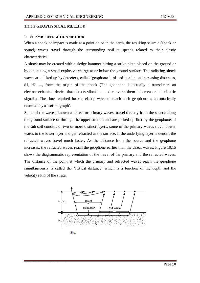
Some of the waves, known as direct or primary waves, travel directly from the source along
the ground surface or through the upper stratum and are picked up first by the geophone. If
the sub soil consists of two or more distinct layers, some of the primary waves travel down-
wards to the lower layer and get refracted as the surface. If the underlying layer is denser, the
refracted waves travel much faster. As the distance from the source and the geophone
increases, the refracted waves reach the geophone earlier than the direct waves. Figure 18.15
shows the diagrammatic representation of the travel of the primary and the refracted waves.
The distance of the point at which the primary and refracted waves reach the geophone
simultaneously is called the ‘critical distance’ which is a function of the depth and the
velocity ratio of the strata.
APPLIED GEOTECHNICAL ENGINEERING 15CV53
ATME College of Engineering Page 11
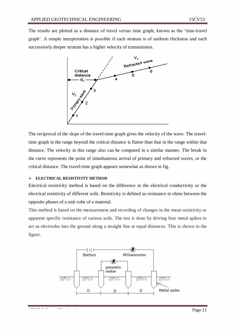
The results are plotted as a distance of travel versus time graph, known as the ‘time-travel
graph’. A simple interpretation is possible if each stratum is of uniform thickness and each
successively deeper stratum has a higher velocity of transmission.
The reciprocal of the slope of the travel-time graph gives the velocity of the wave. The travel-
time graph in the range beyond the critical distance is flatter than that in the range within that
distance. The velocity in this range also can be computed in a similar manner. The break in
the curve represents the point of simultaneous arrival of primary and refracted waves, or the
critical distance. The travel-time graph appears somewhat as shown in fig.
ELECTRICAL RESISTIVITY METHOD
Electrical resistivity method is based on the difference in the electrical conductivity or the
electrical resistivity of different soils. Resistivity is defined as resistance in ohms between the
opposite phases of a unit cube of a material.
This method is based on the measurement and recording of changes in the mean resistivity or
apparent specific resistance of various soils. The test is done by driving four metal spikes to
act as electrodes into the ground along a straight line at equal distances. This is shown in the
figure.
APPLIED GEOTECHNICAL ENGINEERING 15CV53
ATME College of Engineering Page 12
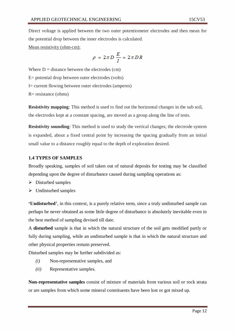
Direct voltage is applied between the two outer potentiometer electrodes and then mean for
the potential drop between the inner electrodes is calculated.
Mean resistivity (ohm-cm):
Where D = distance between the electrodes (cm)
E= potential drop between outer electrodes (volts)
I= current flowing between outer electrodes (amperes)
R= resistance (ohms)
Resistivity mapping: This method is used to find out the horizontal changes in the sub soil,
the electrodes kept at a constant spacing, are moved as a group along the line of tests.
Resistivity sounding: This method is used to study the vertical changes; the electrode system
is expanded, about a fixed central point by increasing the spacing gradually from an initial
small value to a distance roughly equal to the depth of exploration desired.
1.4 TYPES OF SAMPLES
Broadly speaking, samples of soil taken out of natural deposits for testing may be classified
depending upon the degree of disturbance caused during sampling operations as:
Disturbed samples
Undisturbed samples
‘Undisturbed’, in this context, is a purely relative term, since a truly undisturbed sample can
perhaps be never obtained as some little degree of disturbance is absolutely inevitable even in
the best method of sampling devised till date.
A disturbed sample is that in which the natural structure of the soil gets modified partly or
fully during sampling, while an undisturbed sample is that in which the natural structure and
other physical properties remain preserved.
Disturbed samples may be further subdivided as:
(i) Non-representative samples, and
(ii) Representative samples.
Non-representative samples consist of mixture of materials from various soil or rock strata
or are samples from which some mineral constituents have been lost or got mixed up.
APPLIED GEOTECHNICAL ENGINEERING 15CV53
ATME College of Engineering Page 13
Soil samples obtained from auger borings and wash borings are non-representative samples.
These are suitable only for providing qualitative information such as major changes in
subsurface strata.
Representative samples contain all the mineral constituents of the soil, but the structure of
the soil may be significantly disturbed. The water content may also have changed. They are
suitable for identification and for the determination of certain physical properties such as
Atterberg limits and grain specific gravity.
1.5 SAMPLING TECHNIQUES
‘Soil Sampling’ is the process of obtaining samples of soil from the desired depth at the
desired location in a natural soil deposit, with a view to assessing the engineering properties
of the soil for ensuring a proper design of the foundation. The ultimate aim of the exploration
methods described earlier, it must be remembered, is to obtain soil samples besides obtaining
all relevant information regarding the strata. The devices used for the purpose of sampling are
known as ‘soil samplers’.
Soil samples are classified as ‘thick wall’ samplers and ‘thin wall’ samplers. Split spoon
sampler (or split tube sampler) is of the thick-wall type, and ‘Shelby’ tubes are of the thin-
wall type.
Depending upon the mode of operation, samplers may be classified as the open drive
sampler, stationary piston sampler and rotary sampler.
Open drive sampler can be of the thick wall type as well as of the thin wall type. The head
of the sampler is provided with valves to permit water and air to escape during driving. The
check valve helps to retain the sample when the sampler is lifted. The tube may be seamless
or may be split in two parts; in the latter case it is known as the split tube or split spoon
sampler.
Stationary piston sampler consists of a sampler with a piston attached to a long piston rod
extending up to the ground surface through drill rods. The lower end of the sampler is kept
closed with the piston while the sampler is lowered through the bore hole. When the desired
elevation is reached, the piston rod is clamped, thereby keeping the piston stationary, and the
sampler tube is advanced further into the soil. The sampler is then lifted and the piston rod
clamped in position. The piston prevents the entry of water and soil into the tube when it is
being lowered, and also helps to retain the sample during the process of lifting the tube. The
sampler is, therefore, very much suited for sampling in soft soils and saturated sands.
APPLIED GEOTECHNICAL ENGINEERING 15CV53
ATME College of Engineering Page 14
Rotary samplers are of the core barrel type (USBR, 1960) with an outer tube provided with
cutting teeth and a removable thin liner inside. It is used for sampling in stiff cohesive soils.
Split-Spoon Sampler
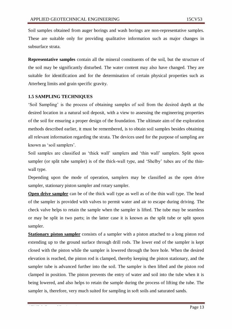
The split spoon sampler is basically a thick-walled steel tube, split length wise. The sampler
as per BIS (IS: 2131-1986—Standard Penetration Test for soils) is shown in Fig.
Fig: Split spoon sampler (I.S.)
A drive shoe attached to the lower end serves as the cutting edge. A sample head may be
screwed at the upper end of split spoon. The standard size of the spoon sampler is of 35 mm
internal and 50.8 mm external diameter. The sampler is lowered to the bottom of the bore
hole by attaching it to the drill rod. The sampler is then driven by forcing it into the soil by
blows from a hammer. The assembly of the sampler is then extracted from the hole and the
cutting edge and coupling at the top are unscrewed. The two halves of the barrel are separated
and the sample is thus exposed. The sample may be placed in a glass jar and sealed, after
visual examination. If samples need not be examined in the field, a liner is inserted inside the
split spoon. After separating the two halves, the liner with the sample is sealed with wax.
APPLIED GEOTECHNICAL ENGINEERING 15CV53
ATME College of Engineering Page 15
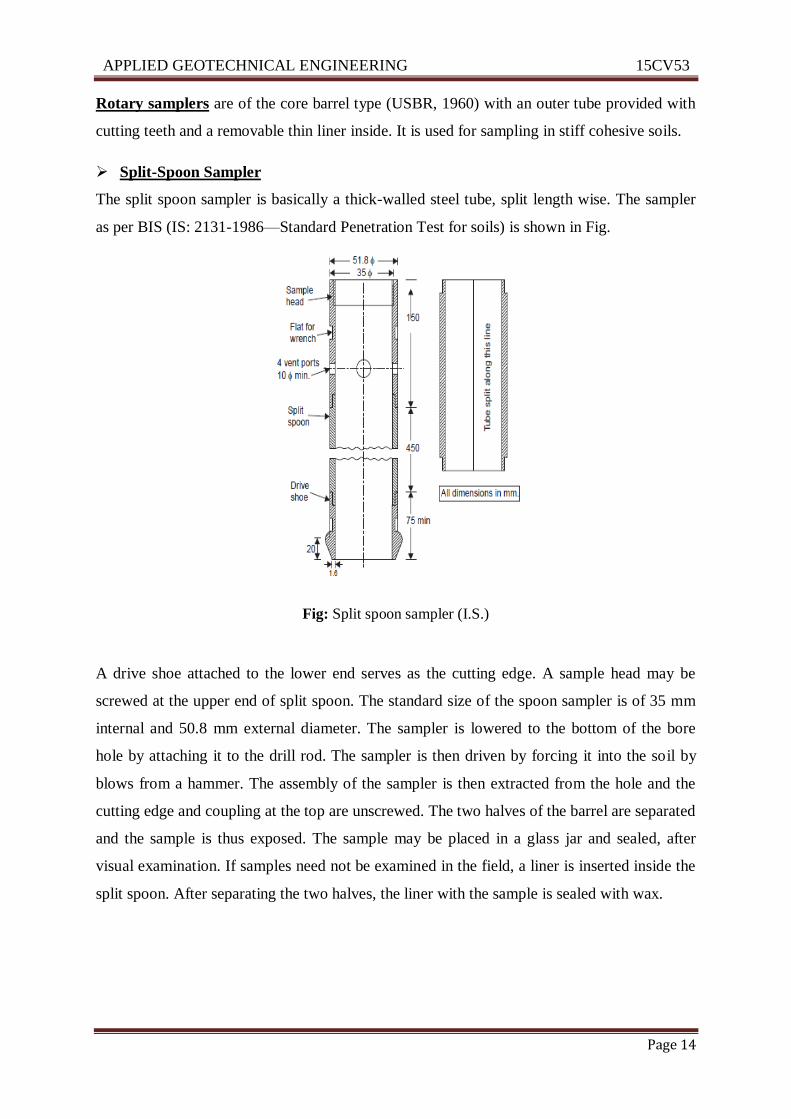
Thin-Walled Samplers
Thin-walled sampler, as per BIS (I.S.: 2132-1986 Code of Practice) for Thin walled Tube
Sampling of Soils), is shown in Fig.
Fig: Thin-walled sampler (I.S.)
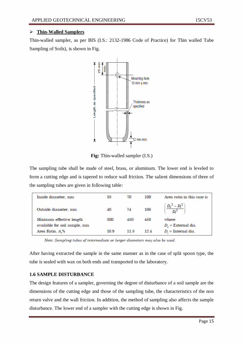
The sampling tube shall be made of steel, brass, or aluminum. The lower end is leveled to
form a cutting edge and is tapered to reduce wall friction. The salient dimensions of three of
the sampling tubes are given in following table:
After having extracted the sample in the same manner as in the case of split spoon type, the
tube is sealed with wax on both ends and transported to the laboratory.
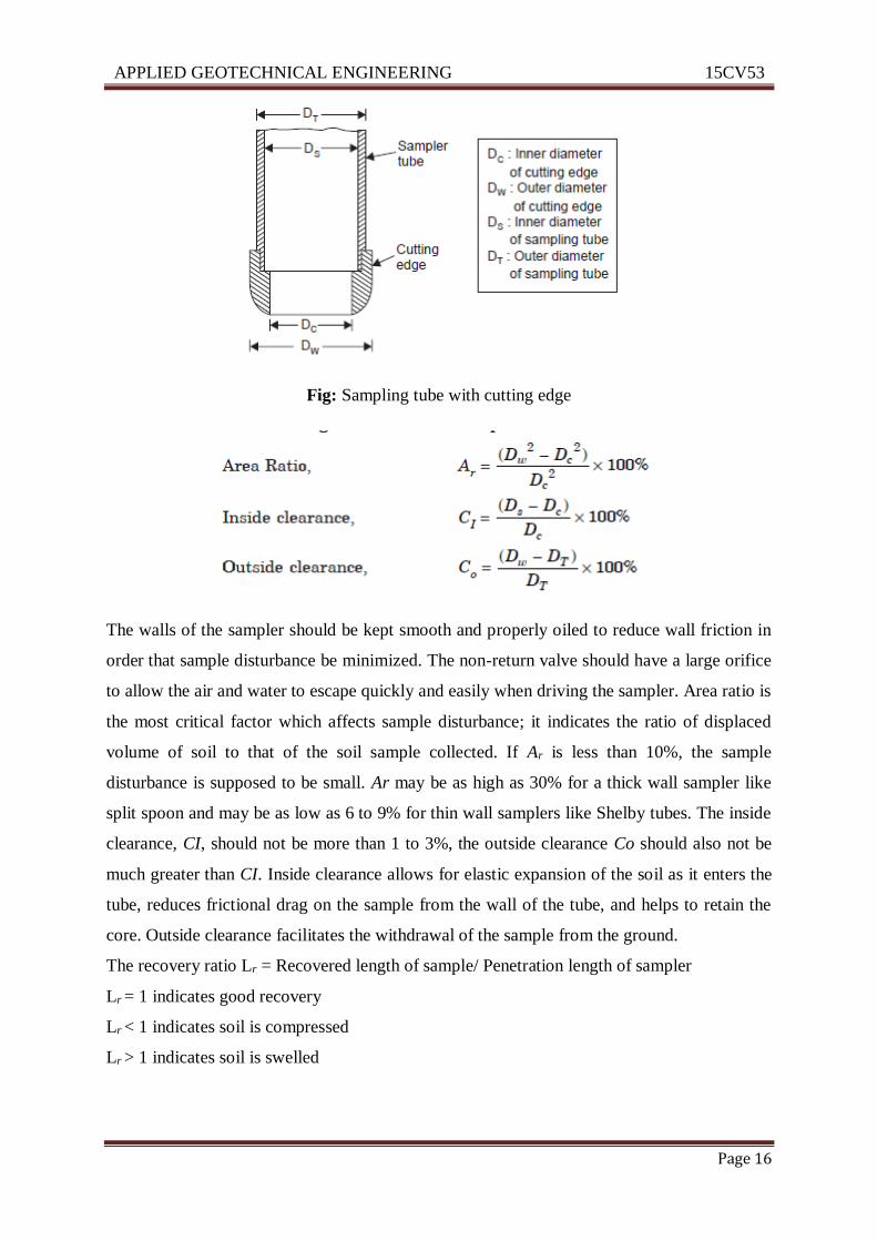
1.6 SAMPLE DISTURBANCE
The design features of a sampler, governing the degree of disturbance of a soil sample are the
dimensions of the cutting edge and those of the sampling tube, the characteristics of the non
return valve and the wall friction. In addition, the method of sampling also affects the sample
disturbance. The lower end of a sampler with the cutting edge is shown in Fig.
APPLIED GEOTECHNICAL ENGINEERING 15CV53
ATME College of Engineering Page 16
Fig: Sampling tube with cutting edge
The walls of the sampler should be kept smooth and properly oiled to reduce wall friction in
order that sample disturbance be minimized. The non-return valve should have a large orifice
to allow the air and water to escape quickly and easily when driving the sampler. Area ratio is
the most critical factor which affects sample disturbance; it indicates the ratio of displaced
volume of soil to that of the soil sample collected. If Ar is less than 10%, the sample
disturbance is supposed to be small. Ar may be as high as 30% for a thick wall sampler like
split spoon and may be as low as 6 to 9% for thin wall samplers like Shelby tubes. The inside
clearance, CI, should not be more than 1 to 3%, the outside clearance Co should also not be
much greater than CI. Inside clearance allows for elastic expansion of the soil as it enters the
tube, reduces frictional drag on the sample from the wall of the tube, and helps to retain the
core. Outside clearance facilitates the withdrawal of the sample from the ground.
The recovery ratio Lr = Recovered length of sample/ Penetration length of sampler
Lr = 1 indicates good recovery
Lr < 1 indicates soil is compressed
Lr > 1 indicates soil is swelled
APPLIED GEOTECHNICAL ENGINEERING 15CV53
ATME College of Engineering Page 17
1.7 STABILIZATION OF BORE HOLE
For geotechnical engineering purposes the borehole is not drilled to its maximum depth in a
single operation. The drilling operation is to be stopped at regular intervals for in-situ testing
and sampling. At all time, the boreholes once drilled must remain as a borehole i.e. the soils
on the sites of the borehole must not cave in and fill up the borehole. Maintaining the
integrity of the borehole is known as stabilization of borehole.
The following methods are commonly employed in practice to stabilize the borehole:
1. Self supportive.
2. Stabilizing by filling with water.
3. Stabilizing by filling with drilling mud.
4. Stabilizing by casing.
SELF SUPPORTIVE
Borehole in clay are usually self supportive. Above the water table such soil has high
apparent cohesion and below the water table enough undrained shear strength to prevent the
soil caving in the borehole.
Silty soil above the water table are also self supportive because of apparent cohesion due to
negative pore water pressure. Below the water table, negative pore water pressure gets
eliminated and borehole needs suitable support.
STABILIZING BY FILLING WITH WATER
When the GWT is at a higher elevation than that of water in the borehole, water flows into
the borehole and seepage forces tends to push the soil into the borehole.
Seepage forces can be used to keep the soil particles in their original position if the direction
of flow is reversed. This can be achieved by filling the boreholes with water to a level above
that of GWT. Boreholes in sites and sandy silts can be stabilized by this method.
STABILIZING BY FILLING WITH DRILLING MUD
Drilling mud is water with bentonite clay. The stabilizing capacity of a drilling mud lies in
the fact that it provides a coating of bentonite on the walls of borehole. This coating of high
plastic material helps coarse grained particle to stick with each other and prevents falling into
the borehole. Since, the level of drilling mud in the borehole is kept higher than GWT, no
flow occurs into the borehole. The disadvantage of using drilling mud is that it is messy.
APPLIED GEOTECHNICAL ENGINEERING 15CV53
ATME College of Engineering Page 18
STABILIZING BY CASING
Casing pipe method of stabilizing borehole is adopted in medium and coarse sand, soft clays
and whenever the other methods do not work. The hole is drilled for a short distance, the
drilling rod is withdrawn and the casing pipe having an outside diameter equal to the
diameter of borehole is pushed into the borehole. Drilling the borehole and penetrating the
casing pipe is to be continued upto the desired depth. The water level in the pipe is to be
maintained at a level higher than GWT.
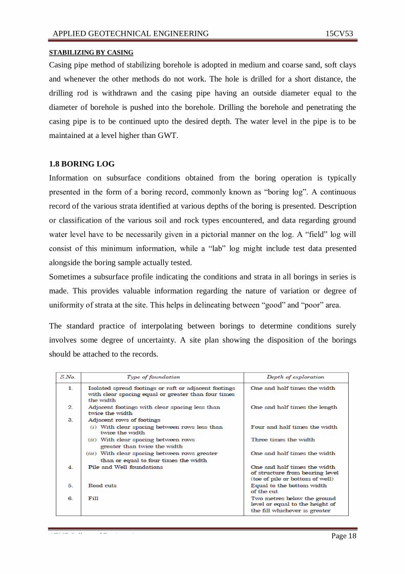
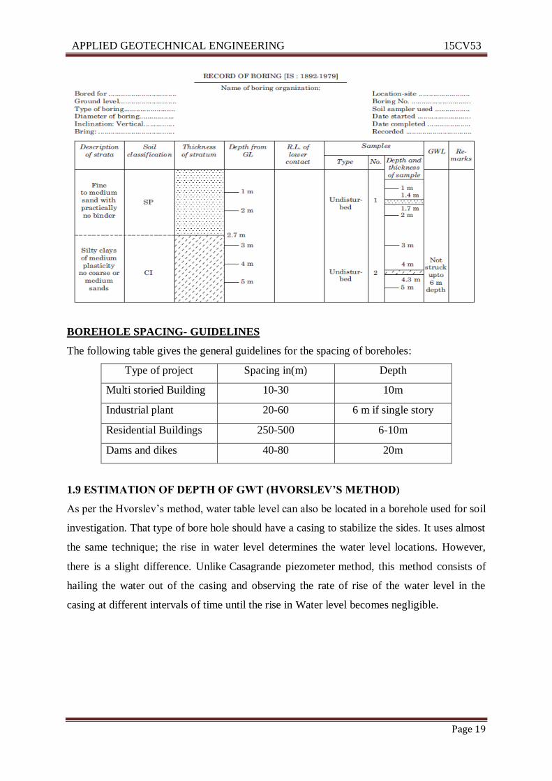
1.8 BORING LOG
Information on subsurface conditions obtained from the boring operation is typically
presented in the form of a boring record, commonly known as “boring log”. A continuous
record of the various strata identified at various depths of the boring is presented. Description
or classification of the various soil and rock types encountered, and data regarding ground
water level have to be necessarily given in a pictorial manner on the log. A “field” log will
consist of this minimum information, while a “lab” log might include test data presented
alongside the boring sample actually tested.
Sometimes a subsurface profile indicating the conditions and strata in all borings in series is
made. This provides valuable information regarding the nature of variation or degree of
uniformity of strata at the site. This helps in delineating between “good” and “poor” area.
The standard practice of interpolating between borings to determine conditions surely
involves some degree of uncertainty. A site plan showing the disposition of the borings
should be attached to the records.
APPLIED GEOTECHNICAL ENGINEERING 15CV53
ATME College of Engineering Page 19
BOREHOLE SPACING- GUIDELINES
The following table gives the general guidelines for the spacing of boreholes:
Type of project Spacing in(m) Depth
Multi storied Building 10-30 10m
Industrial plant 20-60 6 m if single story
Residential Buildings 250-500 6-10m
Dams and dikes 40-80 20m
1.9 ESTIMATION OF DEPTH OF GWT (HVORSLEV’S METHOD)
As per the Hvorslev’s method, water table level can also be located in a borehole used for soil
investigation. That type of bore hole should have a casing to stabilize the sides. It uses almost
the same technique; the rise in water level determines the water level locations. However,
there is a slight difference. Unlike Casagrande piezometer method, this method consists of
hailing the water out of the casing and observing the rate of rise of the water level in the
casing at different intervals of time until the rise in Water level becomes negligible.
APPLIED GEOTECHNICAL ENGINEERING 15CV53
ATME College of Engineering Page 20
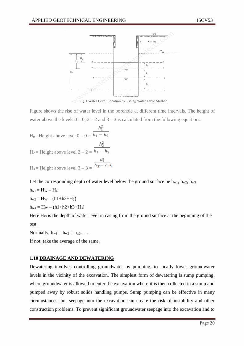
Figure shows the rise of water level in the borehole at different time intervals. The height of
water above the levels 0 – 0, 2 – 2 and 3 – 3 is calculated from the following equations.
Ho = Height above level 0 – 0 =
H2 = Height above level 2 – 2 =
H3 = Height above level 3 – 3 =
Let the corresponding depth of water level below the ground surface be hw1, hw2, hw3
hw1 = HW – HO
hw2 = HW – (h1+h2+H2)
hw3 = HW – (h1+h2+h3+H3)
Here HW is the depth of water level in casing from the ground surface at the beginning of the
test.
Normally, hw1 = hw2 = hw3…...
If not, take the average of the same.
1.10 DRAINAGE AND DEWATERING
Dewatering involves controlling groundwater by pumping, to locally lower groundwater
levels in the vicinity of the excavation. The simplest form of dewatering is sump pumping,
where groundwater is allowed to enter the excavation where it is then collected in a sump and
pumped away by robust solids handling pumps. Sump pumping can be effective in many
circumstances, but seepage into the excavation can create the risk of instability and other
construction problems. To prevent significant groundwater seepage into the excavation and to
APPLIED GEOTECHNICAL ENGINEERING 15CV53
ATME College of Engineering Page 21
ensure stability of excavation side slopes and base it may be necessary to lower groundwater
levels in advance of excavation.
OBJECTIVES OF DEWATERING OR DRAINAGE
• To keep working place dry like excavation for dams, building foundations and tunnels.
• To stabilize natural or constructed slopes
• To treat granular soils by reducing their compressibility
• To decrease lateral pressures on retaining walls or foundation
• To improve bearing capacity of foundation soils
• To reduce liquefaction potential due to seismic activity
• To prevent migration of soil particles by groundwater (phenomenon of piping)
• To reduce surface erosion
METHODS OF DEWATERING
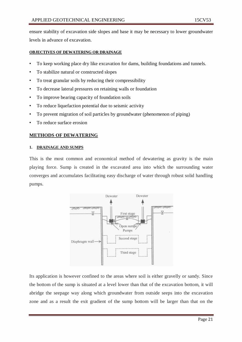
1. DRAINAGE AND SUMPS
This is the most common and economical method of dewatering as gravity is the main
playing force. Sump is created in the excavated area into which the surrounding water
converges and accumulates facilitating easy discharge of water through robust solid handling
pumps.
Its application is however confined to the areas where soil is either gravelly or sandy. Since
the bottom of the sump is situated at a level lower than that of the excavation bottom, it will
abridge the seepage way along which groundwater from outside seeps into the excavation
zone and as a result the exit gradient of the sump bottom will be larger than that on the
APPLIED GEOTECHNICAL ENGINEERING 15CV53
ATME College of Engineering Page 22
excavation surface. If the excavation area is large, several sumps may be placed along the
longer side or simply use a long narrow sump which is called a ditch.
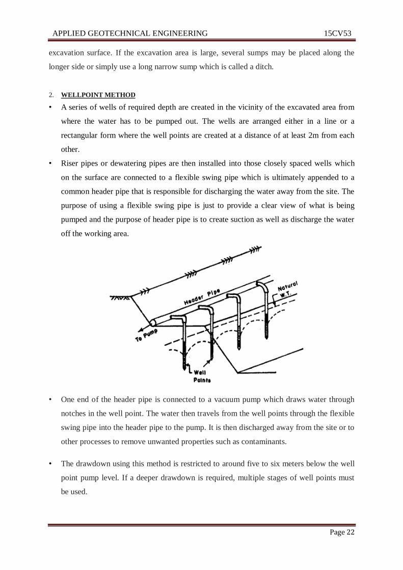
2. WELLPOINT METHOD
• A series of wells of required depth are created in the vicinity of the excavated area from
where the water has to be pumped out. The wells are arranged either in a line or a
rectangular form where the well points are created at a distance of at least 2m from each
other.
• Riser pipes or dewatering pipes are then installed into those closely spaced wells which
on the surface are connected to a flexible swing pipe which is ultimately appended to a
common header pipe that is responsible for discharging the water away from the site. The
purpose of using a flexible swing pipe is just to provide a clear view of what is being
pumped and the purpose of header pipe is to create suction as well as discharge the water
off the working area.
• One end of the header pipe is connected to a vacuum pump which draws water through
notches in the well point. The water then travels from the well points through the flexible
swing pipe into the header pipe to the pump. It is then discharged away from the site or to
other processes to remove unwanted properties such as contaminants.
• The drawdown using this method is restricted to around five to six meters below the well
point pump level. If a deeper drawdown is required, multiple stages of well points must
be used.
APPLIED GEOTECHNICAL ENGINEERING 15CV53
ATME College of Engineering Page 23
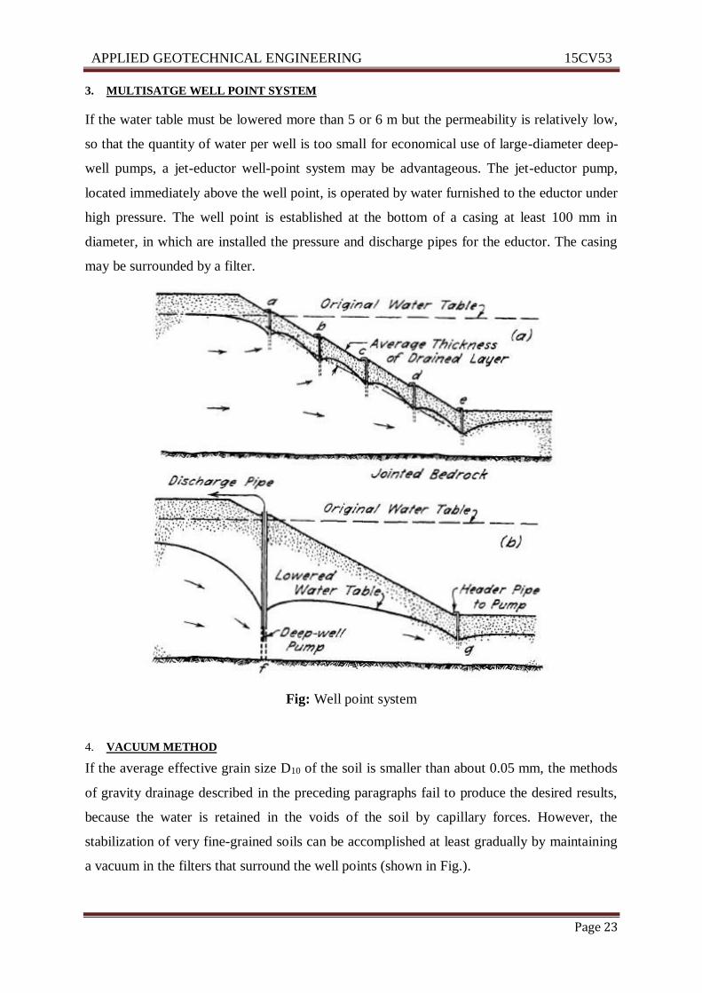
3. MULTISATGE WELL POINT SYSTEM
If the water table must be lowered more than 5 or 6 m but the permeability is relatively low,
so that the quantity of water per well is too small for economical use of large-diameter deep-
well pumps, a jet-eductor well-point system may be advantageous. The jet-eductor pump,
located immediately above the well point, is operated by water furnished to the eductor under
high pressure. The well point is established at the bottom of a casing at least 100 mm in
diameter, in which are installed the pressure and discharge pipes for the eductor. The casing
may be surrounded by a filter.
Fig: Well point system
4. VACUUM METHOD
If the average effective grain size D10 of the soil is smaller than about 0.05 mm, the methods
of gravity drainage described in the preceding paragraphs fail to produce the desired results,
because the water is retained in the voids of the soil by capillary forces. However, the
stabilization of very fine-grained soils can be accomplished at least gradually by maintaining
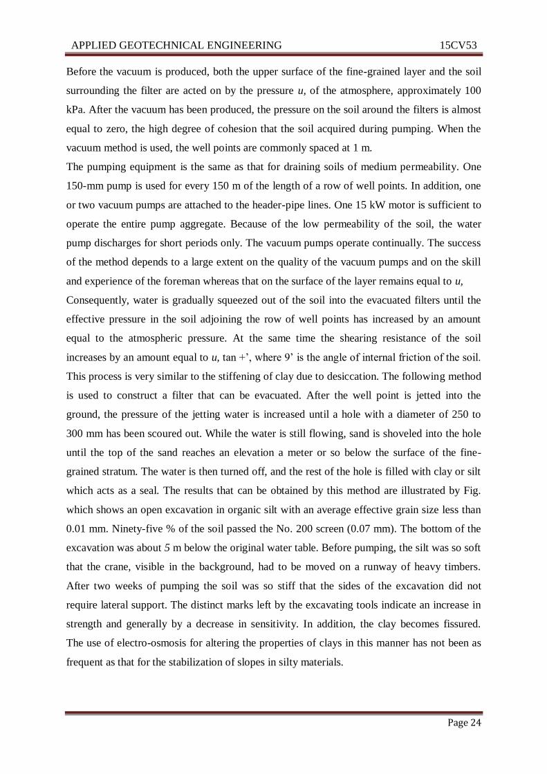
a vacuum in the filters that surround the well points (shown in Fig.).
APPLIED GEOTECHNICAL ENGINEERING 15CV53
ATME College of Engineering Page 24
Before the vacuum is produced, both the upper surface of the fine-grained layer and the soil
surrounding the filter are acted on by the pressure u, of the atmosphere, approximately 100
kPa. After the vacuum has been produced, the pressure on the soil around the filters is almost
equal to zero, the high degree of cohesion that the soil acquired during pumping. When the
vacuum method is used, the well points are commonly spaced at 1 m.
The pumping equipment is the same as that for draining soils of medium permeability. One
150-mm pump is used for every 150 m of the length of a row of well points. In addition, one
or two vacuum pumps are attached to the header-pipe lines. One 15 kW motor is sufficient to
operate the entire pump aggregate. Because of the low permeability of the soil, the water
pump discharges for short periods only. The vacuum pumps operate continually. The success
of the method depends to a large extent on the quality of the vacuum pumps and on the skill
and experience of the foreman whereas that on the surface of the layer remains equal to u,
Consequently, water is gradually squeezed out of the soil into the evacuated filters until the
effective pressure in the soil adjoining the row of well points has increased by an amount
equal to the atmospheric pressure. At the same time the shearing resistance of the soil
increases by an amount equal to u, tan +’, where 9’ is the angle of internal friction of the soil.
This process is very similar to the stiffening of clay due to desiccation. The following method
is used to construct a filter that can be evacuated. After the well point is jetted into the
ground, the pressure of the jetting water is increased until a hole with a diameter of 250 to
300 mm has been scoured out. While the water is still flowing, sand is shoveled into the hole
until the top of the sand reaches an elevation a meter or so below the surface of the fine-
grained stratum. The water is then turned off, and the rest of the hole is filled with clay or silt
which acts as a seal. The results that can be obtained by this method are illustrated by Fig.
which shows an open excavation in organic silt with an average effective grain size less than
0.01 mm. Ninety-five % of the soil passed the No. 200 screen (0.07 mm). The bottom of the
excavation was about 5 m below the original water table. Before pumping, the silt was so soft
that the crane, visible in the background, had to be moved on a runway of heavy timbers.
After two weeks of pumping the soil was so stiff that the sides of the excavation did not
require lateral support. The distinct marks left by the excavating tools indicate an increase in
strength and generally by a decrease in sensitivity. In addition, the clay becomes fissured.
The use of electro-osmosis for altering the properties of clays in this manner has not been as
frequent as that for the stabilization of slopes in silty materials.
APPLIED GEOTECHNICAL ENGINEERING 15CV53
ATME College of Engineering Page 25
Fig: Vacuum tube
ELECTRO-OSMOSIS METHOD
The principle of this method has been earlier. It has most often been applied in practice to the
stabilization of slopes being excavated into cohesion less or slightly cohesive silts below the
normal groundwater level. The time required to drain such materials by the vacuum method
may be excessive, especially under emergency conditions. Yet, the materials readily become
quick under the influence of the seepage pressures directed inward toward the face and
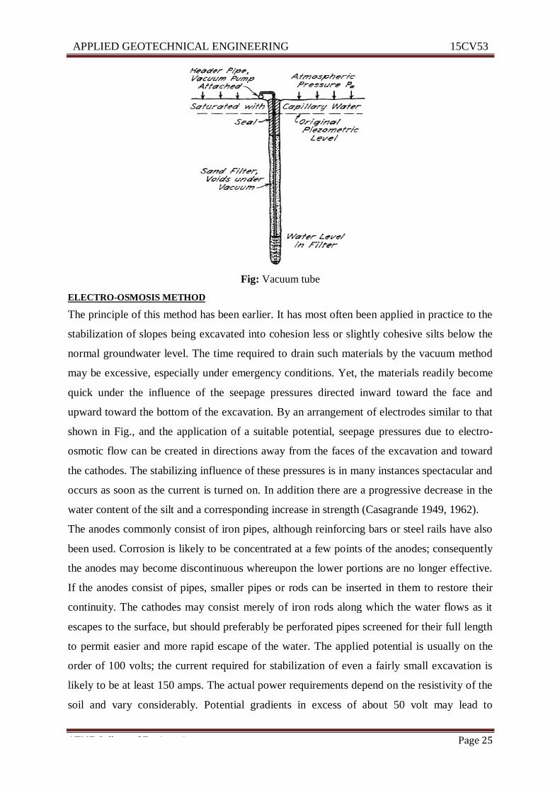
upward toward the bottom of the excavation. By an arrangement of electrodes similar to that
shown in Fig., and the application of a suitable potential, seepage pressures due to electro-
osmotic flow can be created in directions away from the faces of the excavation and toward
the cathodes. The stabilizing influence of these pressures is in many instances spectacular and
occurs as soon as the current is turned on. In addition there are a progressive decrease in the
water content of the silt and a corresponding increase in strength (Casagrande 1949, 1962).
The anodes commonly consist of iron pipes, although reinforcing bars or steel rails have also
been used. Corrosion is likely to be concentrated at a few points of the anodes; consequently
the anodes may become discontinuous whereupon the lower portions are no longer effective.
If the anodes consist of pipes, smaller pipes or rods can be inserted in them to restore their
continuity. The cathodes may consist merely of iron rods along which the water flows as it
escapes to the surface, but should preferably be perforated pipes screened for their full length
to permit easier and more rapid escape of the water. The applied potential is usually on the
order of 100 volts; the current required for stabilization of even a fairly small excavation is
likely to be at least 150 amps. The actual power requirements depend on the resistivity of the
soil and vary considerably. Potential gradients in excess of about 50 volt may lead to
APPLIED GEOTECHNICAL ENGINEERING 15CV53
ATME College of Engineering Page 26
excessive energy loss in the form of heat Electro-osmosis causes consolidation of
compressible soils such as clays. The consolidation is accompanied by the original water
table and the subgrade level. As often as a sample is taken, the water should be allowed to
rise in the casing, and the elevation to which it rises should appear in the boring record.
Excavations in soils with high permeability (k greater than ds) or in very dense mixed-
grained soils of medium permeability (k between and ds) as a rule can be drained without
undue risk by pumping from open sumps. Under favorable conditions uniform soils of
medium permeability can also be drained without mishap by pumping from sumps. However,
this procedure involves the possibility of the formation of boils on the bottom of the
excavation, associated with underground erosion and subsidence of the area surrounding the
excavation. To avoid this risk it is preferable to drain soils of medium permeability by
pumping from well points or filter wells. The drainage of the soil prior to excavation requires
2 to 6 days. The greatest depth to which the water table can be lowered by drawing the water
from one set of wells or well points is about 6m. If the bottom of the proposed excavation is
located at a greater depth, a multiple-stage setup may be used. Two or more header pipes
must be installed at a vertical spacing not exceeding about 5m. If limitations of space do not
permit a multiple-stage installation, eductor well points may be suitable. If the depth of the
excavation exceeds about 15m, it is usually preferable to drain the soil adjoining the site by
means of deep-well pumps operating within the casings of large diameter wells.
Fig: Elecro- osmosis

APPLIED GEOTECHNICAL ENGINEERING 15CV53
ATME College of Engineering Page 27
1.11 RECOMMENDED QUESTIONS
1. What are the objectives of subsurface exploration?
2. Describe with a neat sketch wash boring method of soil exploration.
3. List and explain various types of samplers
4. Explain seismic refraction method of soil exploration with neat sketch.
5. List out the methods of dewatering. Explain Vacuum method of dewatering with neat
sketch
6. In a seismic survey the following readings were obtained
Time(S) 0.1 0.2 0.3 0.4 0.45 0.5 0.55
Distance (m) 40 80 120 160 200 240 280
Geophones are fixed at 40 m in a straight line. Determine:
i) Wave velocity in soil layers
ii) Thickness of top stratum
7. Estimate the ground water level by Hvorslev’s method using the data given. Depth up to
which water is bailed out is 30m, rise in water level after first day is 2.2m, second day
1.8m and on third day it is 1.5m.
8. A sampling tube has inner diameter of 70mm and cutting edge of 68mm. its outside
diameters are 72 mm and 74mm respectively. Determine area ratio, inside clearance,
outside clearance of the sampler. This tube is pushed at the bottom of the borehole to a
distance of 580mm with length of sample recorded being 520mm. find the recovery ratio.
1.12 OUTCOMES
Students should be able to
Decide upon soil exploration techniques to be adopted for different site condition
Conduct soil exploration and to do the report of the same
Collect soil sample by using proper sampling technique base on requirement
Understand dewatering techniques and efficiency of lowering of water table
1.13 FURTHER READING
http://www.yourarticlelibrary.com/soil/soil-exploration-purpose-planning-investigation-
and-tests/45862/
https://theconstructor.org/geotechnical/soil-investigation-and-exploration/2411/