Embed Size (px)
Citation preview

MODULARITY IN SHIPDESIGN AND CONSTRUCTION Rodrigo Pérez, SENER, Madrid/Spain, [email protected] Carlos González, SENER, Madrid/Spain, [email protected] Fernando Sánchez, SENER, Madrid/Spain, [email protected] Fernando Alonso, SENER, Madrid/Spain, [email protected] SUMMARY The proper application of the modularization concepts to accommodation and common spaces demands a complex exercise of coordination among the design of all the systems and disciplines present in such spaces. The analysis of the concept carried out in this paper has strengthen the idea of the necessity to face the modular design approach in the early stages of the design. This is particularly important in the accommodation and common spaces, where the benefit of the increase of the use of the modular solutions is even higher than in other parts of the warship. In this respect the elements associated to the detail 3D model of the standard modules may be used in all kinds of 2D and 3D drawings as well as in reports for further use in production. All the attributes and technological information given to the elements would also be available to be shared with other applications handling other parts of the project: planning, material management and others. The standard module, once designed and saved could be used, instanced, in the 3D model of the warship as many times as required. Modern warships comprise large extends of equipment for propulsion and ship operation which consists of mechanical parts, electronics, tubes, cables, switchboards etc. Machinery equipment contributes significantly to the performance of the warship as well as to material and personnel cost. Modularization can help to reduce the risk of failure by using pre-tested equipment, to reduce purchasing cost as well as to pre-manufacture machinery units in the workshop. The aim of this paper is to develop concepts and design solutions for modular machinery space, on-board automation and warship equipment. In addition methods for modular design are developed and finally the solutions are demonstrated by practical solutions. The machinery spaces form about 15 % of the total outfitting work in a warship of which at least 40 % is still done on-board the ships. The aim is to shift at least 50 % of this work to workshop. NOMENCLATURE CAD/CAM Computer Aided Design/Manufacturing IP Interim Product IT Information Technology 1. INTRODUCTION Modularisation has increased in many industrial sectors, however the naval ships are still built in a traditional way with a lot of outfitting work on-board the vessel. Therefore, modularisation requires new approaches to the entire naval shipbuilding process. Modularity means the creation of interchangeable components or parts of a complex system linked together to perform desired tasks or missions through a set of common standards and interfaces. The US Naval Research Advisory Committee has defined several classes of modularity, including capability swapping modularity (mission-package modularity), component sharing modularity and construction/design modularity. Modularity also involves new business models reflecting the impact of the findings in the commercial shipbuilding. Modularity also allows the warships to be prepared to rapidly reconfigure to ensure the optimum combination of capabilities to pursue high priority missions. For an efficient implementation of the modularity concept in naval ships, it is crucial the use of a Computer Aided Design (CAD/CAM) System incorporating
specific functionalities to handle modularisation, in all design stages. Modularization must be considered in early design stages to analyse the interaction and physical connection between modules: electrical, water, air conditioning, etc. and between modules and the elements surrounding them (see figure 1).
Figure 1: Example of a frigate´s General Arrangement
The commercial shipbuilding world is often recognized by the rapid introduction of advanced capabilities. The naval sector is somehow behind the commercial world in its deployment of new technologies. Modularization holds for the potential to shrink the gap between the naval and commercial worlds. Modularity is not a new concept. It is especially not new to the world military’s design, development and acquisition of platforms or weapons systems.

This paper presents the history behind the concept of module, and shows the implementation in the FORAN System of innovative concepts like the use of the 3D simplified geometry of the standard modules with their connections and attributes and also the possibility of creating and locating instances of modules in the 3D model of the naval ship. The 3D representation of the modules is the simplified geometry of the standard module, and not the 3D detail design in this stage (see figure 2).
Figure 2: Main structure before and after module erection The implementation of the tools, to handle modules in the FORAN System, is particularly important since it remarkably simplifies the analysis mentioned above, what leads to a high potential in the improvement of the coordination among design areas and disciplines, and consequently to a more efficient naval design. The typical naval outfitting and equipment modules for these areas shall be defined, including the interfaces to the equipment and the specification of cables, pipes and air conditioning systems needed for the module. The goal will be to define a limited number of standard modules, which allows exploiting serial effects and containing a significant part of outfitting in order to achieve savings derived from increase of the amount of pre-outfitting. The interfaces of the modules with cables, pipelines, ventilation ducts and also with the surrounding structure can be easily analysed by incorporating the instances of module to the 3D model of the area where the module is to be placed in the 3D model of the warship (see figure 3). In addition, the connection points of the modules in the CAD/CAM System will help to handle the interfaces, by visualizing and assigning user attributes to categorize depending on their type and characteristics.
Figure 3: Accommodation deck on a frigate modelled
with the FORAN CAD/CAM System
In addition to the Introduction (1) and Conclusion (5) sections, this paper has been structured into three sections. Section 2 describes the historical background and evolution of the concept of module, Section 3 is devoted to explain how the build strategy and engineering for production concepts can be used as a possible approach to the definition of modules similarly to other interim products. Finally, in Section 4 it is explained from a designer perspective how to use the new tools implemented in the FORAN System to handle modules. 2. HISTORICAL BACKGROUND AND THE EVOLUTION OF THE CONCEPT OF MODULE Modularity has, during 20th century, received a lot of attention from all industries trying to increase both cost efficiency and customer satisfaction. The term module was however originated in ancient times, when it was given an architectural or structural meaning. Later, along with the industrialisation the term was attached to system parts performing distinct technical functions. Nowadays modularity is most of all seen as a way of handling complexity. From the business point of view the concept has a strong inclination towards standardisation and economies of scale on one hand, and customisation and variability on the other. One of the most important criteria of modularity can thus be said to be the functionality of the module during different stages of its lifecycle. Originally the term module had a purely structural meaning. Last century the term became ever more used for functional distinctions within a product or system. More recently the term has been used to perceive immaterial things such as knowledge, business processes and organisations. Below it is presented the basis for all of these ways to use the concept of module. 2.1 The structural approach The term module is derived from the Latin word modulus, which was a unit of measure in classical architecture. The concept can be regarded to originate from the work of roman architect Marcus Vitruvius Pollio (Vitruve) who worked under the Emperor August. The idea of combining standardisation with functional design received more attention only in the beginning of the 20th century through the paradigm of functionalism when the module was linked to the concept of a building block. It was soon realised that the productivity of building was greatly improved when the building components (modules) were prefabricated, instead of making them on the building site at difficult locations and object to unpredictable situations. The functionality of the building block was not directly connected to the module, as the module still was only related to the geometry of the interface. More recently, the building block concept does not necessarily refer to modules as they can also refer to standard or parametric design such as arrangements, system schematics and/or set of engineering procedures, 2.1.1 Drivers behind modularity

Miller and Elgård (1998) categorise the drivers behind modularity according to: creation of variety, utilisation of similarities and reduction of complexity; or in other words (mass) customisation, standardisation and clarification. 2.1.2 Reducing complexity/increasing manageability Apart from balancing standardisation and customisation many see modularity as a means for handling complexity (Langlois, 2002). Attention was devoted to the real interdependencies between modules. By minimising these interdependencies the work on each module could be done quite independently of each other; i.e. the information needed to carry out the works within one module were hidden from those working outside that module. First of all he distinguished between visible design rules and hidden design parameters (see an example in figure 4) and he continued by claiming that modularization is beneficial only if the partition is precise, unambiguous and complete.
Figure 4: Compartment 3D details in a frigate
2.2 Management and business implications of modularity Whereas the previous point dealt with the concept of modularity from both an engineering and a theoretical point of view, this point seeks to explore the practical economic realities attached to modularity. 2.2.1 Mass customisation As described, the idea of creating variety through modular production was presented already some 40 years ago (Starr, 1965) and well implemented in the car manufacturing industry. The central idea has been to meet specific customer requests at near mass production efficiency.
Figure 5: Example of a Power generation module in the
FORAN System Other authors claim that mass customisation is so similar to many other contemporary concepts, such as lean production, agile manufacturing and concurrent engineering, that a clear boundary cannot be drawn between them. In practical terms, mass customisation can be seen as the production strategy or business concept evolving from a flexible, modular product and process design. A modular design enables the configuration of modules and processes into customer unique deliveries, which as a whole constitute the basis for successful mass customisation (see figure 5). 2.2.2 Flexibility and customisation Mintzberg (1983) have developed a framework to describe the three types of standardisation used for coordination in organisations: standardization of work processes, standardization of output and standardization of skills and knowledge. A central concept in mass customisation is configuration. Configurators are tools for achieving customer integration, e.g. the idea of utilising the customer as a co-designer, as they enable fast and realistic visualisation and simulation of different product configurations. 2.3 Lifecycle engineering and functionality Quite recently lifecycle engineering has become an important concept in management and engineering. Lifecycle engineering approaches seek to ensure optimal functionality throughout all the stages of a product and therefore becomes important for companies that pursue a modular design strategy, since the functionality requirements in different phases of the lifecycle of a product are likely to have implications for decision concerning the product architecture. Ishii (1999) lists four perspectives on functionality of modules: • End user perspective. • Manufacturing perspective (e.g. Engineering for
Production methodologies). • Maintenance perspective. • Recyclability perspective. And most relevant for this paper, Ulrich (1995) suggests that changes to the product are most easily accommodated through modular architectures, due to the

drive for minimisation of interdependencies in such systems. 2.4 Benefits and limitations of modularity Broadly speaking, the benefits of modularity are the same as the main drivers listed: clarification, standardisation and customisation. To be more specific, in the following two sections we will mainly quote Pahl and Beitz (1996), who have listed some generic or usual advantages and disadvantages of modularity. 2.4.1 Advantages of modularity Advantages for the manufacturer: • Read documentation is available for tenders, project
planning and design; designing is done once and for all, though it may be more costly for that very reason.
• Additional design effort is needed for unforeseeable orders only.
• Combinations with non-modules are possible. • Overall scheduling is simplified and delivery dates
may be improved. • The execution of orders by the design and
production departments can be cut short through the production of modules in parallel; in addition parts can be supplied quickly. Computer-aided execution of orders is greatly facilitated. Calculations are simplified.
• Modules can be manufactured for stock with consequent savings.
• More appropriate sub division of assemblies ensures favourable assembly conditions (see figure 6).
• Modular product technology can be applied at successive stages of product development, for example, in product planning, in the preparation of drawings and parts lists, in the purchase of raw materials and semi-finished materials, in the production of parts, in assembly work, and also in marketing.
Figure 6: Save and cooling sub modules
Advantages for the customer include: • Short delivery times. • Better exchange possibilities and easier maintenance. • Better spare parts service. • Possible changes of functions and extensions of the
range. • Almost total elimination of failures thanks to well
developed products. • Benefits derived from the reduction of complexity.
• Benefits associated with the prefabrication (production of one unit tends to be cheaper when performed in a factory than on-site).
2.4.2 Disadvantages, limitations and dangers of modularity Disadvantages/limitations for the manufacturer: • Adaptations to special customer’s wishes are not as
easily made as they are with individual designs (loss of flexibility and market orientation).
• Product changes can only be considered at long intervals because once and for all development costs are high.
Disadvantages for the customer include: • Special wishes cannot be met easily. • Certain quality characteristics may be less
satisfactory than they would be with special purpose designs.
• Weights and structural volumes of modular products are usually greater than those of specially designed products, and so space requirements and foundation costs may increase (in some way this may be compensated by means of the weight reduction associated to a more rational design and arrangement).
• Risks associated to undermining innovation and increasing predictability, allowing thus copy possibilities for competitors.
2.5 Modularity in the naval shipbuilding industry Project based industries share many common features. Still, the group is rather heterogenic in itself. One way to perceive the differences between project based industries is to map the uniqueness of the outcome versus the uniqueness of the construction site. The desired path of evolution in the shipbuilding industry could for instance be to move towards a more standardised outcome that on the other hand would allow for a more decentralised assembly site as different suppliers are expected to carry out ever more work on behalf of the yards. The characteristics of the shipbuilding industry are still in many regards similar to that of the project based industry in general. In any case, the customer should be the starting point for any decision on modular product architectures (Ericsson and Erixon, 1999). In the specific case of machinery spaces, the application of above learnings from other industries will lead to engine rooms initially almost like empty holds so outfitting works can be mainly carried out in rather comfortable workshops where multidisciplinary integrated teams can fabricate an assembly the functional modules (see figure 7).

Figure 7: Integration of several sub-modules in FORAN
An example of modularization in warships is the MEKO family of vessels. It was developed by the German company Bloom + Voss. MEKO (Mehrzweck-Kombination) is an example of conceptual design based on modularity of combat systems and other equipment, aiming to facilitate the maintenance and to reduce the cost. MEKO ships include families of frigates, corvettes and ocean-going patrol boats. Capability-swapping or mission-package modularity also allows for a specific module to be replaced with one of a different type. The most successful example of capability swapping modularity is the Danish Stanflex concept, now nearly 25 years old and present in four classes of warships. The analysis of areas with high potential for modularization will lead, by the application of the criteria decided, to the selection of several standard modules. The modules will be designed and verified in the CAD/CAM and the production simulation Systems for those cases where there is a potential to achieve significant savings by means of the scale economy factor. 3. USING A SINGLE 3D MODEL SYSTEM IN THE MODULAR UNITS DEFINITION To be successful, modularity relies on standard interfaces and configuration management. Standard interfaces are critical in order to ensure that modules and shipboard systems can operate seamlessly once incorporated into a vessel. Configuration management is extremely important, not only to ensure connectivity among systems and components, but also to support rapid technology refresh. Modularity is a valuable way of designing platforms and integrating weapons systems. The benefits of using modularity will reduce the total ownership cost and will increase warship readiness. A modular approach to systems engineering requires the use of an adequate CAD/CAM System. 3.1 DESIGN 3.1.1 Single product model: The design of a ship by using a CAD/CAM System is carried out by producing a soft model as similar as possible to the future real ship. Modifications can be easily performed while the project is going on, improving the design and ensuring a high final quality of it.
The FORAN System manages a single 3D model, with all the information stored in a single and multi-access database. This is a simple way to ensure that all the people working in the project is using the most updated information of each discipline: hull structure, pipework, ductwork, electrical design, etc. The users will be reading and using the information of the single 3D model coordinating the different disciplines in order to reach the best design. 3.1.2 Definition and modification tools: The high standard CAD/CAM Systems usually have flexible tools to define the hull structure and the elements related to outfitting (machinery, deck, accommodation, and electrical components) with a high level of accuracy. Each structure part or outfitting element has attached all the pieces of information, both technical and geometrical that will allow to fabricate them, by obtaining the production outputs. FORAN, as one of the most developed CAD/CAM Systems in the market, has tools that simplify most of the tasks in a ship project, from the initial to the detailed design, covering all the disciplines: forms definition, naval architecture, hull structure, machinery and outfitting, electrical design and accommodation. Across this paper it has been used the terms pre-outfitting units or modular units to refer to the same concept. Their use is a good example of coordination between disciplines because most of them are usually involved in the design of these elements. The point of view of a shipbuilder has been set out in this paper, concerning the use of modular units, types, advantages and drawbacks. For a CAD/CAM System, no matter really the type of unit, the requirement is to have available the necessary tools to define and obtain production information of the modular units. The CAD/CAM System should be flexible enough to be used for any type of unit definition, in different stages and by different shipyards. One of the most powerful applications of a CAD/CAM System when working with modular units is the possibility to use standard ones previously defined for other ships or to adapt them to new design requirements, by changing some elements. The availability of flexible and quick copying and modifying tools is one of the aspects to be considered when selecting a CAD/CAM System. 3.2 Modules in the FORAN System 3.2.1 Short history of the approach to modularization into FORAN System This chapter explains the historical evolution of the concept of module into the FORAN System. The concept of module is not a new subject in FORAN. Modules were initially handled by FORAN by using one of the two approached described below. 3.2.2 Build Strategy Approach The use of the build strategy is a bottom-up approach. The design modules are used to create a 3D model where elements of all the design disciplines are incorporated. At

any point in time, the System allows to group elements from the 3D model into products composed of elements belonging to different disciplines: hull structure, piping, ventilation, electrical, … The products are created by a “build strategy” definition tool and all ship elements can be associated to the products. The System identifies such groups when extracting information from the database when generating both drawings and reports. The approach described in the previous paragraph is still available in the System and is in fact used in several organizations. The name of the current tool into the FORAN System handling the build strategy is FBUILDS. 3.2.2.1 Concept of tree Users can define a tree structure of nodes with a hierarchical relationship among them. The sons of a node inherit the attributes from the parents (see figure 8). The System automatically and internally assigns the elements to a System tree called design tree. The elements are internally classified into categories. Users can define as many trees as they want, simulating different assembly alternatives or even creating different views of the project, not necessarily linked to engineering.
Figure 8: Example of a strategy tree
3.2.2.2 Concept of node into the tree Nodes are entities into each tree that are able to be assigned elements from the 3D model. They can have associated user attributes that are passed from parents to sons, as it is shown in figure 9.
Figure 9: Node properties into the tree
3.2.2.3 Assignment of elements from the 3D model to nodes
The product model, 3D model of the boat (see figure 10), can also be read in FBUILDS. The elements which define the model can be assigned to nodes by using a copy-paste tool.
Figure 10: Example of an IP with outfitting information
3.2.2.4 Results and outputs Once the elements from the 3D model are assigned to trees/nodes, the FORAN tools used to generate outputs can produce drawings and reports based on this assignment. The System can group all the elements associated to a node and all their sons and use such assignment as a filter when reading or reporting from the database/3D model. The outputs, see figure 11, can be customized to display material lists/BoM where only the items or sub-products for the corresponding stage of the assembly process are displayed. This same concept applies to reports using other tools in the System.
Figure 11: Example of an IP output
This approach is particularly suitable to create the set of drawings/reports that need to be used to address the tasks included in the corresponding work package. The System is featured with tools that allow evaluating design aspects that can be directly or indirectly related to cost. In order to perform this analysis and comparison of alternatives, the build strategy tree/s can be used to filter out the part of the boat where the analysis is going to be applied. This is the case of aspects/concepts such as weight or weld length, that can be categorized by types and position. 3.2.3 Approach of assignment of 3D model items to specific module-zones Another approach that was used by some organizations and that is still available in the System uses the ability of

the System to assign the 3D model items belonging to any discipline, except the primary structure, to a zone. Following this approach some specific zones have to be created for this purpose. These specific zones would collect all the items that need to be allocated to the corresponding modules. The 3D model is performed by applying this assignment for as many disciplines as required, e.g. equipment layout, equipment seats, piping, HVAC, electrical and their supports. The zones are then available to filter elements out when generating the outputs, either for the reporting tools or for the generation of drawings. In this case zones could be used as well to filter the module data for both the arrangement and the manufacturing drawings. Below the main ideas in which it is based the new approach to handle modules in the early stages of the design are described. Anticipating the benefits of applying the modularization approach, the objective is to create the tools that would allow handling efficiently the increase in the use of modules. The analysis is done from a generic point of view, so most of the ideas may be applied to any CAD/CAM System (CADSYS). Some other ideas have been thought for the particular data structure of the FORAN System and then they lose this general validity. 4. MODULARIZATION FEATURES INSIDE THE CAD SYSTEM 4.1 DEFINITION OF MODULES Main functionalities implemented in the FORAN System to handle modules are described below. 4.1.1 Standards Manager The objective of this Manager is to facilitate the definition of standard modules. It allows to create new standard files (modules), to rename them and to delete them. Modules can be organised in folders. The System displays on the upper part of the right hand side of the dialog window the list of the standard modules defined (see figure 12). Standard modules can be displayed either as a list or as a tree structure.
Figure 12: Dialog window to handle standard modules
A simplified geometrical representation, as well as connections and attributes can be associated to the standard modules. Filters can also be used to facilitate the search of specific types of modules. Functionalities are grouped in tabs: basic data, simplified model, detailed model and connections.
4.1.1.1 Basic data The basic data tab allows to carry out the actions described below (see figure 13).
Figure 13: Basic data functionality window
Each standard module has an identification (user id) and a Description. The Edit attributes functionality allows to allocate values to the user attributes associated to the standard module entity (see figure 14).
Figure 14: User attributes for the standard module
4.1.1.2 Simplified model
Figure 15: Simplified model functionality window
A 3D simplified model must be associated to each standard module. The simplified model is defined usually by means of a macro file that will provide the simplified 3D geometry of the standard module (see figure 15). This allows to take advantage of the powerful capabilities of the FORAN macros.
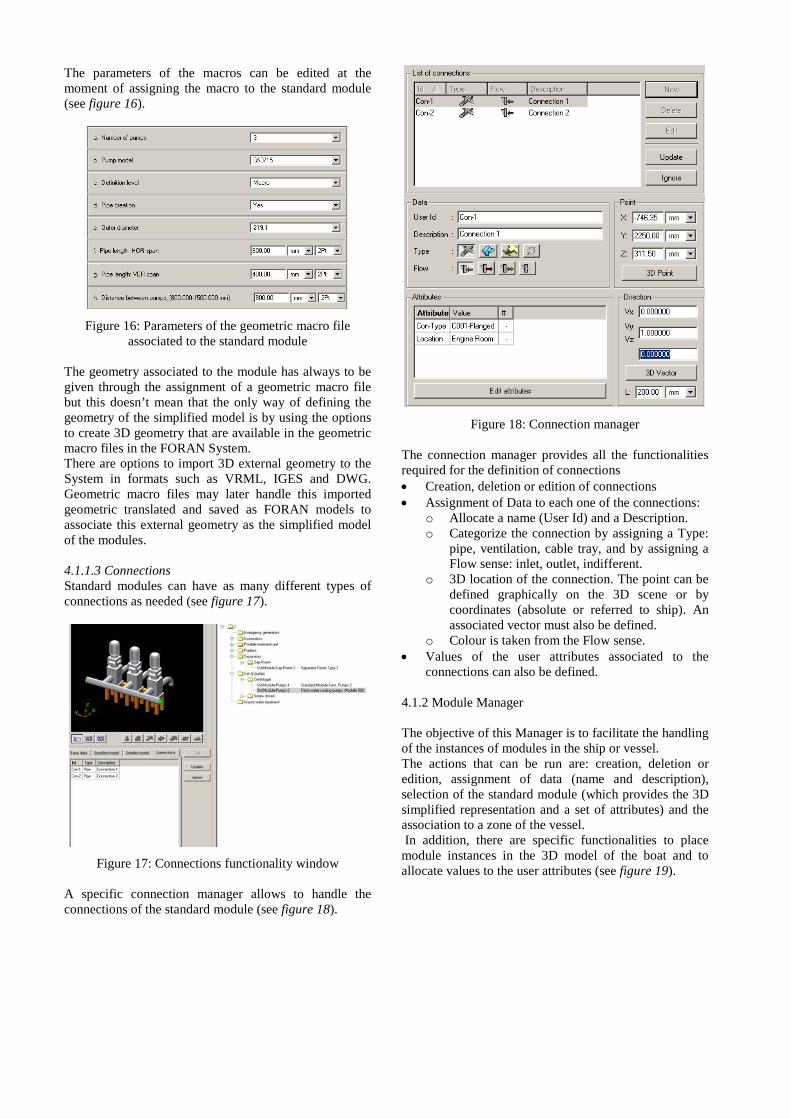
The parameters of the macros can be edited at the moment of assigning the macro to the standard module (see figure 16).
Figure 16: Parameters of the geometric macro file
associated to the standard module The geometry associated to the module has always to be given through the assignment of a geometric macro file but this doesn’t mean that the only way of defining the geometry of the simplified model is by using the options to create 3D geometry that are available in the geometric macro files in the FORAN System. There are options to import 3D external geometry to the System in formats such as VRML, IGES and DWG. Geometric macro files may later handle this imported geometric translated and saved as FORAN models to associate this external geometry as the simplified model of the modules. 4.1.1.3 Connections Standard modules can have as many different types of connections as needed (see figure 17).
Figure 17: Connections functionality window
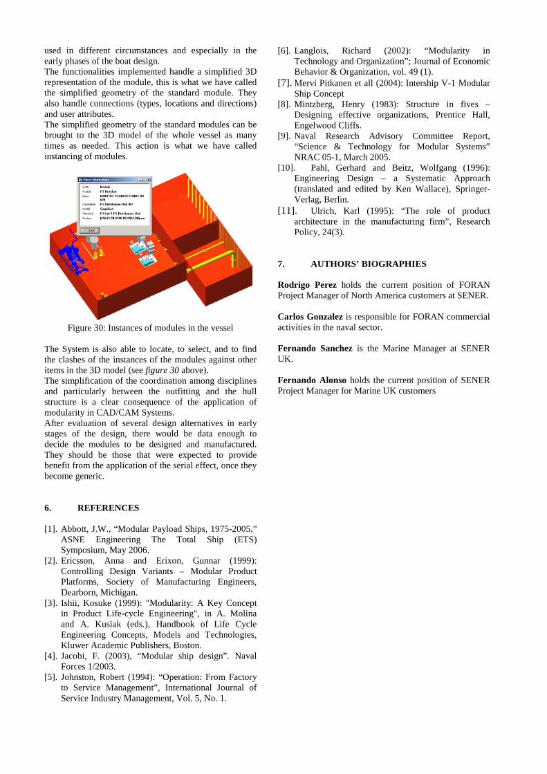
A specific connection manager allows to handle the connections of the standard module (see figure 18).
Figure 18: Connection manager
The connection manager provides all the functionalities required for the definition of connections • Creation, deletion or edition of connections • Assignment of Data to each one of the connections:
o Allocate a name (User Id) and a Description. o Categorize the connection by assigning a Type:
pipe, ventilation, cable tray, and by assigning a Flow sense: inlet, outlet, indifferent.
o 3D location of the connection. The point can be defined graphically on the 3D scene or by coordinates (absolute or referred to ship). An associated vector must also be defined.
o Colour is taken from the Flow sense. • Values of the user attributes associated to the
connections can also be defined. 4.1.2 Module Manager The objective of this Manager is to facilitate the handling of the instances of modules in the ship or vessel. The actions that can be run are: creation, deletion or edition, assignment of data (name and description), selection of the standard module (which provides the 3D simplified representation and a set of attributes) and the association to a zone of the vessel. In addition, there are specific functionalities to place module instances in the 3D model of the boat and to allocate values to the user attributes (see figure 19).

Figure 19: Module manager
When required, Modules can also be read from the database and brought to the 3D scene. The available functionalities are explained with some more detail below. 4.1.2.1 Creation, Edition and Deletion of modules
Instances of standards modules can be created, modified or deleted at any moment. The existing instances of modules can be displayed either as a list or as a tree structure under the zone to which each module instance is assigned. The assignment of each instance of module to a zone of the vessel is mandatory. 4.1.2.2 Data of the Instance of the Module: identification, standard module
The following data has to be assigned to each instance of the standard module: • User identification. • Description. • Standard module associated to the instance: it will
lead to the simplified geometry. • Zone to which the module instance is assigned. 4.1.2.3 Attributes of the Instance of the Module
The current allocation of values to the user attributes associated to a particular instance of a module is displayed, allowing to allocate new values to the user attributes or to modify the current allocation (see figure 20 below).
Figure 20: User attributes inside the Manager of Modules 4.1.2.4 Position: place, remove
The instances of the modules are placed in the 3D model of the vessel. Modules can be removed at any moment. Coordinates of the positioning point are also displayed
(absolute and boat coordinates (frame, deck, half breadth)). 4.1.3 Attributes The System associates default attributes to the different elements into the vessel database. In addition it is possible to define user attributes for them. There is no restriction in the number of attributes that can be assigned to an element, particularly to the standard modules, to the module instances and to the connections of the modules. The user attributes are given a Name and a Description. They can be declared as Compulsory or not and can be Linked to another attribute. If linked to another attribute they would only be activated when the main attribute gets the value Yes. The values can be of different types: Integer, Float, Date, String, Table, etc. User attributes can be assigned to standard modules, to connections and to module instances. As many attributes as needed can be assigned to these types of elements. Attributes can be shared among different types, can also be copied from one type to another, or can be a completely different set of attributes for each one of the types. Each one of the attributes can be given a default value, which will be offered by the System as the tentative value of the corresponding attribute when creating an item of the corresponding type in the Database.
Figure 21: Standard Module Type
In the example of the image above, figure 21, the type of element Standard Module has associated a set of attributes that are listed in the upper part of the dialog window: Delivery Date, Installation Time, Material, Price, Supplied, Supplier and Type. The attribute called Supplier has been edited. It has been created as Compulsory and as Linked to the attribute Supplied (Yes/No). It is declared as type Table, and the values are taken from a table called Tab_Supplier. It has been allocated the value C001 (Supplier 1), the default one. Below are shown two examples of lists of attributes associated to the entities Connection and Instance of module: • Attributes of the connections: the edited attribute in
the example is been declared as type String (figure 22).

Figure 22: Attributes of the connections
• Attributes of the instances of Modules: the edited
attribute in the example is been declared as type Integer (figure 23).
Figure 23: Attributes of the Modules
The attributes of the entities can be used as filters as explained in the next paragraph. 4.1.4 Filters Filters can be used to refine the search of modules in the Database in two different situations. The use is the same in both situations and it will be explained below. These situations are the following: • User attributes filters for Standard Modules • User attributes filters for Modules Below they are shown several examples of the use of user attributes as filters. It is shown how the System automatically applies different criteria to each one of them depending on the type of attribute that was selected when it was declared: values typed by the user for the type string, values selected from the table for the type table, values or interval of values for the type integer or float, etc. In the case of user attributes values type table shown in figure 24.
Figure 24: User attribute type table filters for Module
In the case of user attributes values type integer (see figure 25):
Figure 25: User attribute type integer filters for Module
In the case of user attributes values type Boolean, Yes/ No (see figure 26):
Figure 26: User attribute type Boolean filters for Module 4.2 OUTPUTS 4.2.1 Selecting and filtering the information to be displayed in the outputs The first step in the generation of module drawings is to bring to the scene, together with items from other disciplines, the modules already placed in the vessel in previous sessions, by accessing to the list of instances of modules in the project. Multi-selection facilities are available. In the image below, figure 27, the list of instances of modules is shown as a list, instead of in a tree structure.

Figure 27: List of instances of modules
Filters can be used for the selection of the instances. The filters will be set by activating the restrictions of the user attributes or of the zones. An example of the use of restrictions is shown in the image below, figure 28. In this case just one instance of module complies with the set of restrictions.
Figure 28: User attributes filter for selection of instances 4.2.2 Modules on drawings Once selected and brought to the 3D scene the information to be displayed in the drawings, all the tools available in the System to generate views, to perform sections, to create and add details to the drawings and to annotate on them by adding labels can be used. Dimensioning, display of relative distances between items or references of these items to the vessel can also be generated. Below it is shown an example of a drawing of the module FO Distribution unit (see figure 29 below) with a simplified geometry that has been imported from a VRML file. The drawing also displays some other items defined with FORAN: hull structure, equipment, piping and outfitting structures.
Figure 29: Drawing example of the module FO
Distribution unit
4.3 SECURITY As regards naval vessel, the CAD/CAM System must also incorporate tools and functionalities to ensure the access control to the vessel restricted information (e.g. ITAR), which means it would be possible to define security markings to the entities subject to control: modules, other equipment items… The capability of determining access rights levels for authenticated users on a specific entity would be defined by cross-referencing both the user and the entity security markings profile. Some rules would be defined and agreed to establish user access level to the entity according to the results of this process. FORAN is able to manage access control permissions at the required level. A new representation group (Secure) is available to be used for each model object. The aim of this level is to contain the geometry to be shown to non-authorized users during reading process.
5. CONCLUSIONS During the analysis previous to the introduction of the modular ship concept in FORAN, it was concluded that for generic modules the focus should be on the development of technical solutions, standardisation, parameterisation and the introduction of industrialised manufacturing. When it comes to ship specific modules (instances of modules) it is necessary to make sure that the design methods and procedures facilitate the handling of modules in the vessel. The approach to manage generic and specific modules in FORAN is done through the concepts of standard modules and instances of modules. In the new tools implemented in the System it has been given existence to the concept of standard module with connections and attributes as well as with an associated simplified geometry. The simplified geometry gives a rough 3D geometrical representation for the module instances, linked to the standard module. It also allows to apply some degree of parameterization. In addition, it allows to analyse and evaluate different design alternatives and interfaces, taking into consideration the surroundings. It is particularly suitable in early stages of the design. In the detail design phase of the vessel, this simplified geometry will be refined, by performing the detail design of the standard module, with all the necessary information to manufacture and mount it. From the analysis carried out in this paper, it is also clear that the practical application of the modularization on a specific vessel in a specific shipyard may still require some parametric adjustment or tuning, but the design criteria, the methodology and the understanding of the performance of the modularised solution might still be valid. The solution that has been implemented in FORAN to handle modules is generic, so it is flexible enough to be
used in different circumstances and especially in the early phases of the boat design. The functionalities implemented handle a simplified 3D representation of the module, this is what we have called the simplified geometry of the standard module. They also handle connections (types, locations and directions) and user attributes. The simplified geometry of the standard modules can be brought to the 3D model of the whole vessel as many times as needed. This action is what we have called instancing of modules.
Figure 30: Instances of modules in the vessel
The System is also able to locate, to select, and to find the clashes of the instances of the modules against other items in the 3D model (see figure 30 above). The simplification of the coordination among disciplines and particularly between the outfitting and the hull structure is a clear consequence of the application of modularity in CAD/CAM Systems. After evaluation of several design alternatives in early stages of the design, there would be data enough to decide the modules to be designed and manufactured. They should be those that were expected to provide benefit from the application of the serial effect, once they become generic. 6. REFERENCES [1]. Abbott, J.W., “Modular Payload Ships, 1975-2005,”
ASNE Engineering The Total Ship (ETS) Symposium, May 2006.
[2]. Ericsson, Anna and Erixon, Gunnar (1999): Controlling Design Variants – Modular Product Platforms, Society of Manufacturing Engineers, Dearborn, Michigan.
[3]. Ishii, Kosuke (1999): "Modularity: A Key Concept in Product Life-cycle Engineering", in A. Molina and A. Kusiak (eds.), Handbook of Life Cycle Engineering Concepts, Models and Technologies, Kluwer Academic Publishers, Boston.
[4]. Jacobi, F. (2003), “Modular ship design”. Naval Forces 1/2003.
[5]. Johnston, Robert (1994): “Operation: From Factory to Service Management”, International Journal of Service Industry Management, Vol. 5, No. 1.
[6]. Langlois, Richard (2002): “Modularity in Technology and Organization”; Journal of Economic Behavior & Organization, vol. 49 (1).
[7]. Mervi Pitkanen et all (2004): Intership V-1 Modular Ship Concept
[8]. Mintzberg, Henry (1983): Structure in fives – Designing effective organizations, Prentice Hall, Engelwood Cliffs.
[9]. Naval Research Advisory Committee Report, “Science & Technology for Modular Systems” NRAC 05-1, March 2005.
[10]. Pahl, Gerhard and Beitz, Wolfgang (1996): Engineering Design – a Systematic Approach (translated and edited by Ken Wallace), Springer-Verlag, Berlin.
[11]. Ulrich, Karl (1995): “The role of product architecture in the manufacturing firm”, Research Policy, 24(3).
7. AUTHORS’ BIOGRAPHIES Rodrigo Perez holds the current position of FORAN Project Manager of North America customers at SENER. Carlos Gonzalez is responsible for FORAN commercial activities in the naval sector. Fernando Sanchez is the Marine Manager at SENER UK. Fernando Alonso holds the current position of SENER Project Manager for Marine UK customers