Embed Size (px)
Citation preview
ModularVariable SpeedAir Handlers
2TEE3F31A1000A 4TEE3F31B1000A2TEE3F37A1000A 4TEE3F37B1000A2TEE3F39A1000A 4TEE3F39A1000A2TEE3F40A1000A 4TEE3F40B1000A2TEE3F48A1000A 4TEE3F48A1000A2TEE3F49A1000A 4TEE3F49B1000A2TEE3F64A1000A 4TEE3F64A1000A2TEE3F65A1000A 4TEE3F65B1000A
PUB. NO. 22-1717-05
2 Pub. No. 22-1717-05© 2008 Trane
Optional Equipment
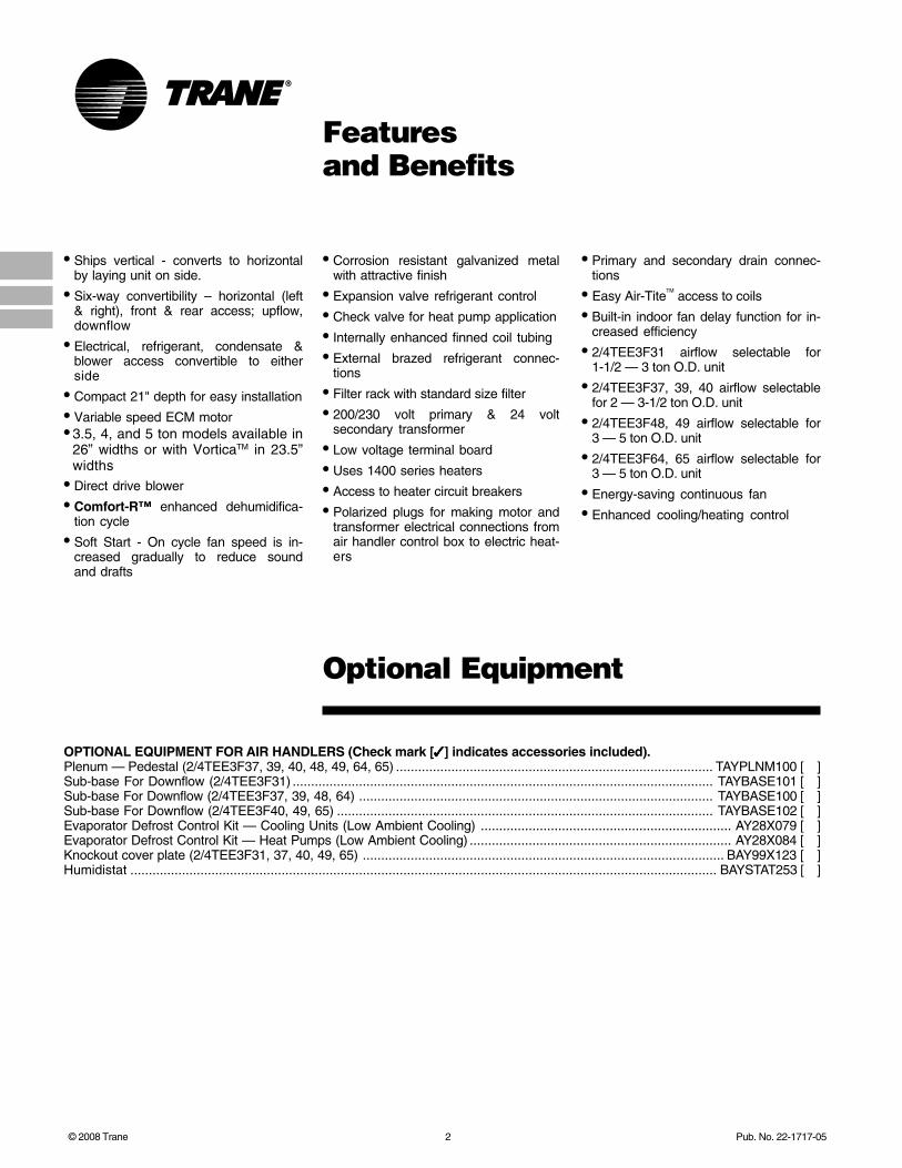
OPTIONAL EQUIPMENT FOR AIR HANDLERS (Check mark [✓✓✓✓✓] indicates accessories included).Plenum — Pedestal (2/4TEE3F37, 39, 40, 48, 49, 64, 65) ...................................................................................... TAYPLNM100 [ ]Sub-base For Downflow (2/4TEE3F31) .................................................................................................................. TAYBASE101 [ ]Sub-base For Downflow (2/4TEE3F37, 39, 48, 64) ................................................................................................ TAYBASE100 [ ]Sub-base For Downflow (2/4TEE3F40, 49, 65) ...................................................................................................... TAYBASE102 [ ]Evaporator Defrost Control Kit — Cooling Units (Low Ambient Cooling) .................................................................... AY28X079 [ ]Evaporator Defrost Control Kit — Heat Pumps (Low Ambient Cooling) ....................................................................... AY28X084 [ ]Knockout cover plate (2/4TEE3F31, 37, 40, 49, 65) .................................................................................................. BAY99X123 [ ]Humidistat ............................................................................................................................................................... BAYSTAT253 [ ]
Featuresand Benefits
• Ships vertical - converts to horizontalby laying unit on side.
• Six-way convertibility – horizontal (left& right), front & rear access; upflow,downflow
• Electrical, refrigerant, condensate &blower access convertible to eitherside
• Compact 21" depth for easy installation
• Variable speed ECM motor• 3.5, 4, and 5 ton models available in
26” widths or with VorticaTM in 23.5”widths
• Direct drive blower
• Comfort-R™ enhanced dehumidifica-tion cycle
• Soft Start - On cycle fan speed is in-creased gradually to reduce soundand drafts
• Corrosion resistant galvanized metalwith attractive finish
• Expansion valve refrigerant control
• Check valve for heat pump application
• Internally enhanced finned coil tubing
• External brazed refrigerant connec-tions
• Filter rack with standard size filter
• 200/230 volt primary & 24 voltsecondary transformer
• Low voltage terminal board
• Uses 1400 series heaters
• Access to heater circuit breakers
• Polarized plugs for making motor andtransformer electrical connections fromair handler control box to electric heat-ers
• Primary and secondary drain connec-tions
• Easy Air-TiteTM
access to coils
• Built-in indoor fan delay function for in-creased efficiency
• 2/4TEE3F31 airflow selectable for1-1/2 — 3 ton O.D. unit
• 2/4TEE3F37, 39, 40 airflow selectablefor 2 — 3-1/2 ton O.D. unit
• 2/4TEE3F48, 49 airflow selectable for3 — 5 ton O.D. unit
• 2/4TEE3F64, 65 airflow selectable for3 — 5 ton O.D. unit
• Energy-saving continuous fan
• Enhanced cooling/heating control

Pub. No. 22-1717-05 3
Contents
Features and Benefits 2Optional Equipment 2
“Air-Tite™” Features and Benefits 4
General Data 52TEE3F31A1000A 4TEE3F31B1000A 52TEE3F37A1000A 4TEE3F37B1000A 52TEE3F39A1000A 4TEE3F39A1000A 52TEE3F40A1000A 4TEE3F40B1000A 52TEE3F48A1000A 4TEE3F48A1000A 52TEE3F49A1000A 4TEE3F49B1000A 62TEE3F64A1000A 4TEE3F64A1000A 62TEE3F65A1000A 4TEE3F65B1000A 6
Performance Data 7
Electrical Data 20
Field Wiring 21
Convertibility 22
Dimensions 23
Mechanical Specification Options 26
4 Pub. No. 22-1717-05
“Air-Tite™”Features and Benefits
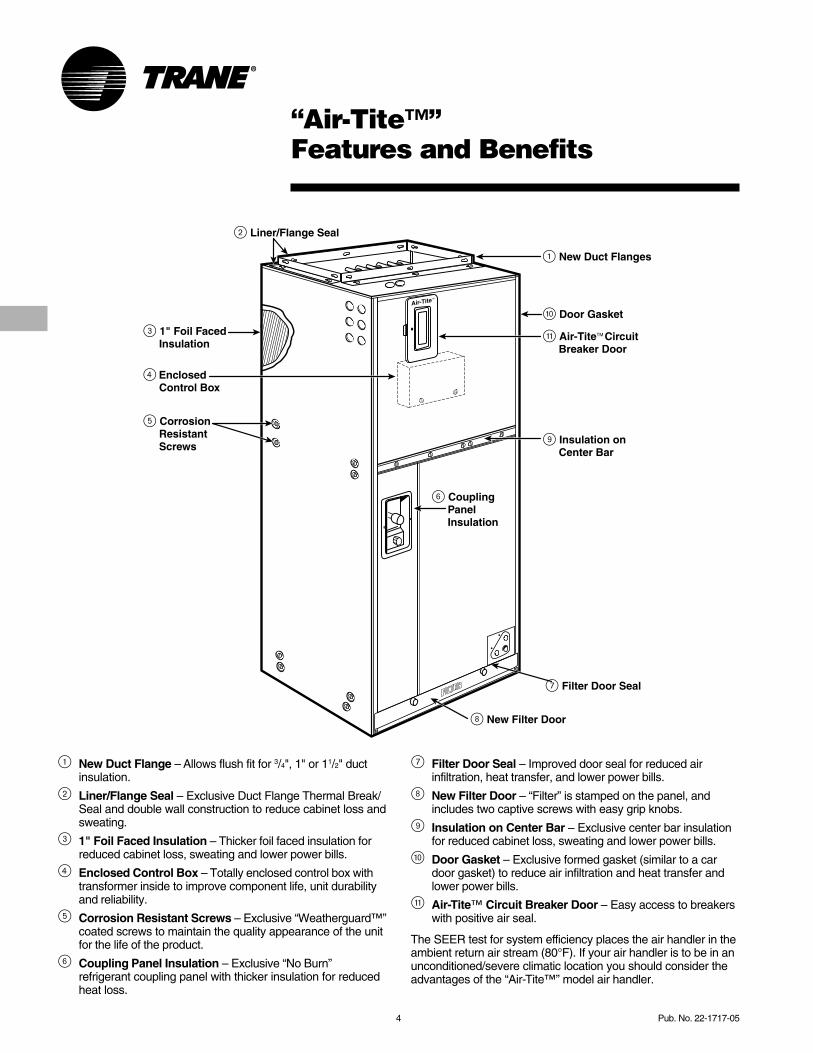
1 New Duct Flange – Allows flush fit for 3/4", 1" or 11/2" ductinsulation.
2 Liner/Flange Seal – Exclusive Duct Flange Thermal Break/Seal and double wall construction to reduce cabinet loss andsweating.
3 1" Foil Faced Insulation – Thicker foil faced insulation forreduced cabinet loss, sweating and lower power bills.
4 Enclosed Control Box – Totally enclosed control box withtransformer inside to improve component life, unit durabilityand reliability.
5 Corrosion Resistant Screws – Exclusive “Weatherguard™”coated screws to maintain the quality appearance of the unitfor the life of the product.
6 Coupling Panel Insulation – Exclusive “No Burn”refrigerant coupling panel with thicker insulation for reducedheat loss.
7 Filter Door Seal – Improved door seal for reduced airinfiltration, heat transfer, and lower power bills.
8 New Filter Door – “Filter” is stamped on the panel, andincludes two captive screws with easy grip knobs.
9 Insulation on Center Bar – Exclusive center bar insulationfor reduced cabinet loss, sweating and lower power bills.
0 Door Gasket – Exclusive formed gasket (similar to a cardoor gasket) to reduce air infiltration and heat transfer andlower power bills.
q Air-Tite™ Circuit Breaker Door – Easy access to breakerswith positive air seal.
The SEER test for system efficiency places the air handler in theambient return air stream (80°F). If your air handler is to be in anunconditioned/severe climatic location you should consider theadvantages of the “Air-Tite™” model air handler.

Pub. No. 22-1717-05 5
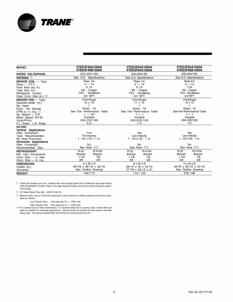
MODEL
RATED VOLTS/PH/HZ.RATINGS 1
INDOOR COIL — TypeRows — F.P.I.Face Area (sq. ft.)Tube Size (in.)Refrigerant ControlDrain Conn. Size (in.) 2
INDOOR FAN — TypeDiameter-Width (In.)No. UsedDrive - No. SpeedsCFM vs. in. w.g. 1No. Motors — H.P.Motor Speed R.P.M.Volts/Ph/HzF.L. Amps - L.R. AmpsFILTERVertical ApplicationsFilter Furnished?Type RecommendedNo.-Size-ThicknessHorizontal ApplicationsFilter Furnished?Recommended SizeREFRIGERANTRef. Line ConnectionsConn. Size — in. GasConn. Size — in. Liq.DIMENSIONSCrated (In.)UncratedWEIGHT
GeneralData
MODEL
RATED VOLTS/PH/HZ.RATINGS 1
INDOOR COIL — TypeRows — F.P.I.Face Area (sq. ft.)Tube Size (in.)Refrigerant ControlDrain Conn. Size (in.) 2
INDOOR FAN — TypeDiameter-Width (In.)No. UsedDrive - No. SpeedsCFM vs. in. w.g. 1No. Motors — H.P.Motor Speed R.P.M.Volts/Ph/HzF.L. Amps - L.R. AmpsFILTERVertical ApplicationsFilter Furnished?Type RecommendedNo.-Size-ThicknessHorizontal ApplicationsFilter Furnished?Recommended SizeREFRIGERANTRef. Line ConnectionsConn. Size — in. GasConn. Size — in. Liq.DIMENSIONSCrated (In.)UncratedWEIGHT
2TEE3F31A1000A4TEE3F31B1000A
200-230/1/60See O.D. Specifications
Plate Fin3 — 14
3.213/8 - Copper
TXV - NonBleed3/4 NPT
Centrifugal10 x 8
1Direct - 16
See Fan Performance Table1 — 1/2Variable
200-230/1/604.3
YesLow Velocity
1 - 20 X 20 - 1 in.
N oSee Note 34
R-22 R-410ABrazed Brazed
3/4 3/45/16 5/16
H x W x D44-1/2 x 24 x 23-1/2See Outline Drawing
134 / 118
2TEE3F37A1000A4TEE3F37B1000A
200-230/1/60See O.D. Specifications
Plate Fin3 — 14
3.93/8 - Copper
TXV - NonBleed3/4 NPT
Centrifugal10 x 10
1Direct - 16
See Fan Performance Table1 — 1/2Variable
200-230/1/604.3
YesLow Velocity
1 - 20 X 20 - 1 in.
NoSee Note 34
R-22 R-410ABrazed Brazed
7/8 3/43/8 3/8
H x W x D47-7/8 x 26 x 23-1/2See Outline Drawing
142 / 127
2TEE3F39A1000A4TEE3F39A1000A
200-230/1/60See O.D. Specifications
Plate Fin3 — 14
5.043/8 - Copper
TXV - NonBleed3/4 NPT
Centrifugal11 x 10
1Direct - 16
See Fan Performance Table1 — 1/2Variable
200-230/1/604.3
YesThrowaway
1 - 20 X 20 - 1 in.
N oSee Note 34
R-22 R-410ABrazed Brazed
7/8 3/43/8 3/8
H x W x D59-1/2 x 26 x 23-1/257-7/8 x 23-1/2 x 21
160 / 150
2TEE3F48A1000A4TEE3F48A1000A
200-230/1/60See O.D. Specifications
Plate Fin3 — 14
6.193/8 - Copper
TXV - NonBleed3/4 NPT
Centrifugal11 x 10
1Direct - 16
See Fan Performance Table1 — 3/4Variable
200-230/1/606.8
YesThrowaway
1 - 20 x 20 x 1 in.
N oSee Note 34
R-22 R-410ABrazed Brazed
1-1/8 7/8 3/8 3/8
H x W x D59-1/2 x 26 x 23-1/257-7/8 x 23-1/2 x 21
170/155
1 These Air Handlers are A.R.I. certified withvarious Split System Air Conditioners andHeat Pumps (ARI STANDARD 210/240).Refer to the Split System Outdoor UnitProduct Data Guides for performance data.
2 3/4" Male Plastic Pipe (Ref.: ASTM 1785-76)
3 Minimum filter size for horizontalapplications will be based on airflowselection and will be calculated as follows: Low Velocity Filter: Face area (Sq. Ft.) = CFM / 300 High Velocity Filter: Face area (Sq. Ft.) = CFM / 500
4 For customer ease of filter maintenance, it isrecommended that a properly sized, remotefilter and grille be installed for horizontalapplications. Airflow should not exceed theface value of the filter being used. Thefactory installed filter should then beremoved from the unit.
2TEE3F40A1000A4TEE3F40B1000A
200-230/1/60See O.D. Specifications
Plate Fin4 — 14
5.043/8 - Copper
TXV - NonBleed3/4 NPT
Centrifugal10 x 10
1Direct - 16
See Fan Performance Table1 — 1/2Variable
200-230/1/604.3
YesLow Velocity
1 - 20 X 25 - 1 in.
N oSee Note 34
R-22 R-410ABrazed Brazed
7/8 3/43/8 3/8
H x W x D54-1/2 x 28-1/2 x 23-1/2
See Outline Drawing174 / 155
6 Pub. No. 22-1717-05
MODEL
RATED VOLTS/PH/HZ.RATINGS 1
INDOOR COIL — TypeRows — F.P.I.Face Area (sq. ft.)Tube Size (in.)Refrigerant ControlDrain Conn. Size (in.) 2
INDOOR FAN — TypeDiameter-Width (In.)No. UsedDrive - No. SpeedsCFM vs. in. w.g. 1No. Motors — H.P.Motor Speed R.P.M.Volts/Ph/HzF.L. Amps - L.R. AmpsFILTERVertical ApplicationsFilter Furnished?Type RecommendedNo.-Size-ThicknessHorizontal ApplicationsFilter Furnished?Recommended SizeREFRIGERANTRef. Line ConnectionsConn. Size — in. GasConn. Size — in. Liq.DIMENSIONSCrated (In.)UncratedWEIGHT
2TEE3F49A1000A4TEE3F49B1000A
200-230/1/60See O.D. Specifications
Plate Fin4 — 14
6.193/8 - Copper
TXV - NonBleed3/4 NPT
Centrifugal10 x 10
1Direct - 16
See Fan Performance Table1 — 3/4Variable
200-230/1/606.8
YesThrowaway
1 - 20 x 25 x 1 in.
N oSee Note 34
R-22 R-410ABrazed Brazed
1-1/8 7/8 3/8 3/8
H x W x D60-7/6 x 28-1/2 x 23-1/2
See Outline Drawing188/173
2TEE3F64A1000A4TEE3F64A1000A
200-230/1/60See O.D. Specifications
Plate Fin3 — 14
6.193/8 - Copper
TXV - NonBleed3/4 NPT
Centrifugal11 x 10
1Direct - 16
See Fan Performance Table1 — 1
Variable200-230/1/60
7.0
YesLow Velocity
1 - 20 X 22 - 1 in.
NoSee Note 34
R-22 R-410ABrazed Brazed
1-1/8 7/8 3/8 3/8
H x W x D59-1/2 x 26 x 23-1/257-7/8 x 23-1/2 x 21
170 / 155
2TEE3F65A1000A4TEE3F65B1000A
200-230/1/60See O.D. Specifications
Plate Fin4 — 14
7.333/8 - Copper
TXV - NonBleed3/4 NPT
Centrifugal10 x 10
1Direct - 16
See Fan Performance Table1 — 1
Variable200-230/1/60
7.0
YesLow Velocity
1 - 20 X 25 - 1 in.
NoSee Note 34
R-22 R-410ABrazed Brazed
1-1/8 7/8 3/8 3/8
H x W x D65-78 x 28-1/2 x 23-1/2
See Outline Drawing218 / 196
1 These Air Handlers are A.R.I. certified with various Split System Air Conditioners and Heat Pumps(ARI STANDARD 210/240). Refer to the Split System Outdoor Unit Product Data Guides for perfor-mance data.
2 3/4" Male Plastic Pipe (Ref.: ASTM 1785-76)
3 Minimum filter size for horizontal applications will be based on airflow selection and will be calcu-lated as follows:
Low Velocity Filter: Face area (Sq. Ft.) = CFM / 300
High Velocity Filter: Face area (Sq. Ft.) = CFM / 5004 For customer ease of filter maintenance, it is recommended that a properly sized, remote filter and
grille be installed for horizontal applications. Airflow should not exceed the face value of the filterbeing used. The factory installed filter should then be removed from the unit.
Pub. No. 22-1717-05 7
PerformanceData
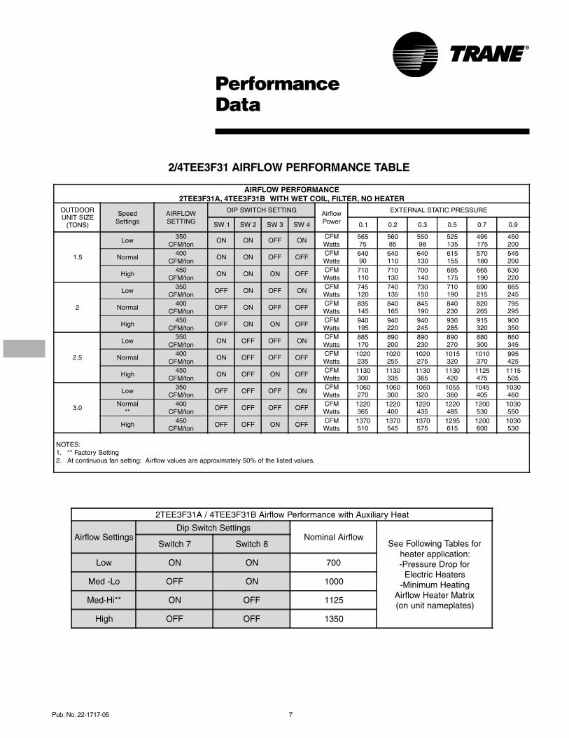
2/4TEE3F31 AIRFLOW PERFORMANCE TABLE
AIRFLOW PERFORMANCE2TEE3F31A, 4TEE3F31B WITH WET COIL, FILTER, NO HEATER
OUTDOORUNIT SIZE
(TONS)
SpeedSettings
AIRFLOWSETTING
DIP SWITCH SETTING AirflowPower
EXTERNAL STATIC PRESSURE
SW 1 SW 2 SW 3 SW 4 0.1 0.2 0.3 0.5 0.7 0.9
1.5
Low350
CFM/tonON ON OFF ON
CFMWatts
56575
56085
55098
525135
495175
450200
Normal400
CFM/tonON ON OFF OFF
CFMWatts
64090
640110
640130
615155
570180
545200
High450
CFM/tonON ON ON OFF
CFMWatts
710110
710130
700140
685175
665190
630220
2
Low350
CFM/tonOFF ON OFF ON
CFMWatts
745120
740135
730150
710190
690215
665245
Normal400
CFM/tonOFF ON OFF OFF
CFMWatts
835145
840165
845190
840230
820265
795295
High450
CFM/tonOFF ON ON OFF
CFMWatts
940195
940220
940245
930285
915320
900350
2.5
Low350
CFM/tonON OFF OFF ON
CFMWatts
885170
890200
890230
890270
880300
860345
Normal400
CFM/tonON OFF OFF OFF
CFMWatts
1020235
1020255
1020275
1015320
1010370
995425
High450
CFM/tonON OFF ON OFF
CFMWatts
1130300
1130335
1130365
1130420
1125475
1115505
3.0
Low350
CFM/tonOFF OFF OFF ON
CFMWatts
1060270
1060300
1060320
1055360
1045405
1030460
Normal**
400CFM/ton
OFF OFF OFF OFFCFMWatts
1220365
1220400
1220435
1220485
1200530
1030550
High450
CFM/tonOFF OFF ON OFF
CFMWatts
1370510
1370545
1370575
1295615
1200600
1030530
NOTES: 1. ** Factory Setting 2. At continuous fan setting: Airflow values are approximately 50% of the listed values.
2TEE3F31A / 4TEE3F31B Airflow Performance with Auxiliary Heat
Airflow SettingsDip Switch Settings
Nominal AirflowSee Following Tables for
heater application:-Pressure Drop for
Electric Heaters-Minimum Heating
Airflow Heater Matrix(on unit nameplates)
Switch 7 Switch 8
Low ON ON 700
Med -Lo OFF ON 1000
Med-Hi** ON OFF 1125
High OFF OFF 1350
8 Pub. No. 22-1717-05
PerformanceData
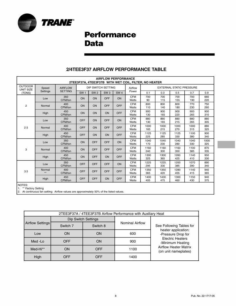
2/4TEE3F37 AIRFLOW PERFORMANCE TABLE
AIRFLOW PERFORMANCE2TEE3F37A, 4TEE3F37B WITH WET COIL, FILTER, NO HEATER
OUTDOORUNIT SIZE
(TONS)
SpeedSettings
AIRFLOWSETTING
DIP SWITCH SETTING AirflowPower
EXTERNAL STATIC PRESSURE
SW 1 SW 2 SW 3 SW 4 0.1 0.3 0.5 0.7 0.9
2
Low350
CFM/tonON ON OFF ON
CFMWatts
70090
700115
700155
700190
660220
Normal400
CFM/tonON ON OFF OFF
CFMWatts
800110
800140
800180
770230
750260
High450
CFM/tonON ON ON OFF
CFMWatts
900130
900165
900220
900265
900310
2.5
Low350
CFM/tonOFF ON OFF ON
CFMWatts
880130
880165
880215
880265
880305
Normal400
CFM/tonOFF ON OFF OFF
CFMWatts
1000165
1000215
1000270
1000315
880325
High450
CFM/tonOFF ON ON OFF
CFMWatts
1125225
1125285
1125330
1100380
900340
3
Low350
CFM/tonON OFF OFF ON
CFMWatts
1040170
1040230
1040280
1040330
1000325
Normal400
CFM/tonON OFF OFF OFF
CFMWatts
1160240
1160300
1160350
1100385
870335
High450
CFM/tonON OFF ON OFF
CFMWatts
1300325
1300365
1260425
1140410
950330
3.5
Low350
CFM/tonOFF OFF OFF ON
CFMWatts
1225295
1225330
1200385
1070390
890340
Normal**
400CFM/ton
OFF OFF OFF OFFCFMWatts
1350365
1350420
1280455
1140415
940365
High450
CFM/tonOFF OFF ON OFF
CFMWatts
1400405
1400475
1300460
1150430
940375
NOTES: 1. ** Factory Setting 2. At continuous fan setting: Airflow values are approximately 50% of the listed values.
2TEE3F37A / 4TEE3F37B Airflow Performance with Auxiliary Heat
Airflow SettingsDip Switch Settings
Nominal AirflowSee Following Tables for
heater application:-Pressure Drop for
Electric Heaters-Minimum Heating
Airflow Heater Matrix(on unit nameplates)
Switch 7 Switch 8
Low ON ON 600
Med -Lo OFF ON 900
Med-Hi** ON OFF 1100
High OFF OFF 1400
Pub. No. 22-1717-05 9
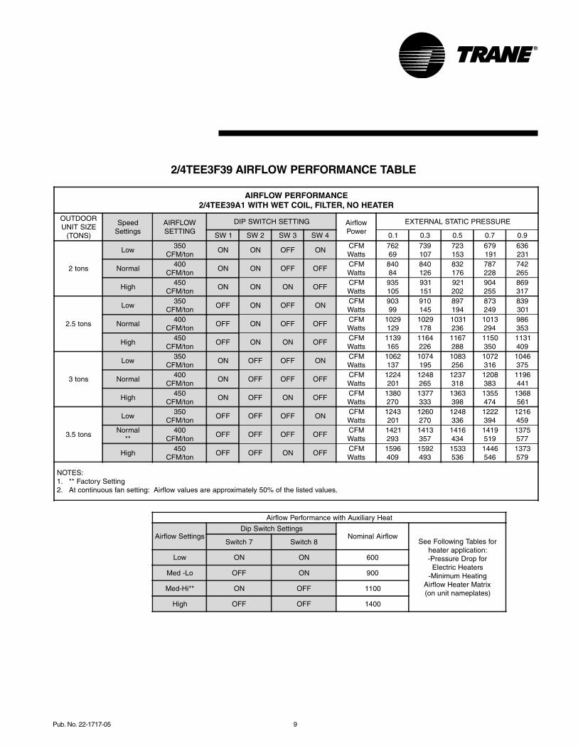
2/4TEE3F39 AIRFLOW PERFORMANCE TABLE
AIRFLOW PERFORMANCE2/4TEE39A1 WITH WET COIL, FILTER, NO HEATER
OUTDOORUNIT SIZE
(TONS)
SpeedSettings
AIRFLOWSETTING
DIP SWITCH SETTING AirflowPower
EXTERNAL STATIC PRESSURE
SW 1 SW 2 SW 3 SW 4 0.1 0.3 0.5 0.7 0.9
2 tons
Low350
CFM/tonON ON OFF ON
CFMWatts
76269
739107
723153
679191
636231
Normal400
CFM/tonON ON OFF OFF
CFMWatts
84084
840126
832176
787228
742265
High450
CFM/tonON ON ON OFF
CFMWatts
935105
931151
921202
904255
869317
2.5 tons
Low350
CFM/tonOFF ON OFF ON
CFMWatts
90399
910145
897194
873249
839301
Normal400
CFM/tonOFF ON OFF OFF
CFMWatts
1029129
1029178
1031236
1013294
986353
High450
CFM/tonOFF ON ON OFF
CFMWatts
1139165
1164226
1167288
1150350
1131409
3 tons
Low350
CFM/tonON OFF OFF ON
CFMWatts
1062137
1074195
1083256
1072316
1046375
Normal400
CFM/tonON OFF OFF OFF
CFMWatts
1224201
1248265
1237318
1208383
1196441
High450
CFM/tonON OFF ON OFF
CFMWatts
1380270
1377333
1363398
1355474
1368561
3.5 tons
Low350
CFM/tonOFF OFF OFF ON
CFMWatts
1243201
1260270
1248336
1222394
1216459
Normal**
400CFM/ton
OFF OFF OFF OFFCFMWatts
1421293
1413357
1416434
1419519
1375577
High450
CFM/tonOFF OFF ON OFF
CFMWatts
1596409
1592493
1533536
1446546
1373579
NOTES: 1. ** Factory Setting 2. At continuous fan setting: Airflow values are approximately 50% of the listed values.
Airflow Performance with Auxiliary Heat
Airflow SettingsDip Switch Settings
Nominal AirflowSee Following Tables for
heater application:-Pressure Drop for
Electric Heaters-Minimum Heating
Airflow Heater Matrix(on unit nameplates)
Switch 7 Switch 8
Low ON ON 600
Med -Lo OFF ON 900
Med-Hi** ON OFF 1100
High OFF OFF 1400

10 Pub. No. 22-1717-05
PerformanceData
2/4TEE3F40 AIRFLOW PERFORMANCE TABLE
AIRFLOW PERFORMANCE2TEE3F40A, 4TEE3F40B WITH WET COIL, FILTER, NO HEATER
OUTDOORUNIT SIZE
(TONS)
SpeedSettings
AIRFLOWSETTING
DIP SWITCH SETTING AirflowPower
EXTERNAL STATIC PRESSURE
SW 1 SW 2 SW 3 SW 4 0.1 0.2 0.3 0.5 0.7 0.9
2
Low350
CFM/tonON ON OFF ON
CFMWatts
74590
725105
700120
620150
595185
555225
Normal400
CFM/tonON ON OFF OFF
CFMWatts
825105
810120
790140
750190
710215
675250
High450
CFM/tonON ON ON OFF
CFMWatts
910135
910150
910166
875205
845275
770305
2.5
Low350
CFM/tonOFF ON OFF ON
CFMWatts
870125
865140
855160
820205
805255
750280
Normal400
CFM/tonOFF ON OFF OFF
CFMWatts
1000165
1000185
1000205
980245
940290
890340
High450
CFM/tonOFF ON ON OFF
CFMWatts
1130210
1125235
1115255
1100305
1080350
1055400
3
Low350
CFM/tonON OFF OFF ON
CFMWatts
1075185
1070200
1060220
1025275
985315
945365
Normal400
CFM/tonON OFF OFF OFF
CFMWatts
1200235
1200260
1195290
1185355
1170440
1145475
High450
CFM/tonON OFF ON OFF
CFMWatts
1350300
1365345
1375380
1375440
1350495
1320550
3.5
Low350
CFM/tonOFF OFF OFF ON
CFMWatts
1215245
1215270
1210300
1205355
1190405
1160460
Normal**
400CFM/ton
OFF OFF OFF OFFCFMWatts
1400345
1400395
1400435
1400485
1400530
1400575
High450
CFM/tonOFF OFF ON OFF
CFMWatts
1415355
1425390
1430435
1425495
1405545
1365595
NOTES: 1. ** Factory Setting 2. At continuous fan setting: Airflow values are approximately 50% of the listed values.
2TEE3F40A / 4TEE3F31B Airflow Performance with Auxiliary Heat
Airflow SettingsDip Switch Settings
Nominal AirflowSee Following Tables for
heater application:-Pressure Drop for
Electric Heaters-Minimum Heating
Airflow Heater Matrix(on unit nameplates)
Switch 7 Switch 8
Low ON ON 600
Med -Lo OFF ON 900
Med-Hi** ON OFF 1100
High OFF OFF 1400
Pub. No. 22-1717-05 11
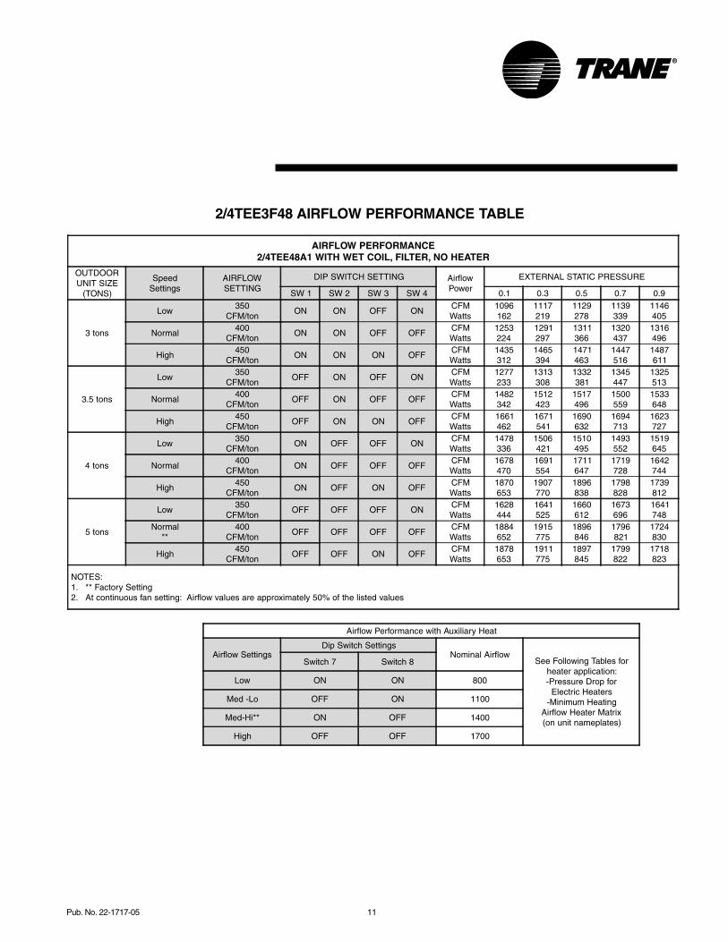
2/4TEE3F48 AIRFLOW PERFORMANCE TABLE
AIRFLOW PERFORMANCE2/4TEE48A1 WITH WET COIL, FILTER, NO HEATER
OUTDOORUNIT SIZE
(TONS)
SpeedSettings
AIRFLOWSETTING
DIP SWITCH SETTING AirflowPower
EXTERNAL STATIC PRESSURE
SW 1 SW 2 SW 3 SW 4 0.1 0.3 0.5 0.7 0.9
3 tons
Low350
CFM/tonON ON OFF ON
CFMWatts
1096162
1117219
1129278
1139339
1146405
Normal400
CFM/tonON ON OFF OFF
CFMWatts
1253224
1291297
1311366
1320437
1316496
High450
CFM/tonON ON ON OFF
CFMWatts
1435312
1465394
1471463
1447516
1487611
3.5 tons
Low350
CFM/tonOFF ON OFF ON
CFMWatts
1277233
1313308
1332381
1345447
1325513
Normal400
CFM/tonOFF ON OFF OFF
CFMWatts
1482342
1512423
1517496
1500559
1533648
High450
CFM/tonOFF ON ON OFF
CFMWatts
1661462
1671541
1690632
1694713
1623727
4 tons
Low350
CFM/tonON OFF OFF ON
CFMWatts
1478336
1506421
1510495
1493552
1519645
Normal400
CFM/tonON OFF OFF OFF
CFMWatts
1678470
1691554
1711647
1719728
1642744
High450
CFM/tonON OFF ON OFF
CFMWatts
1870653
1907770
1896838
1798828
1739812
5 tons
Low350
CFM/tonOFF OFF OFF ON
CFMWatts
1628444
1641525
1660612
1673696
1641748
Normal**
400CFM/ton
OFF OFF OFF OFFCFMWatts
1884652
1915775
1896846
1796821
1724830
High450
CFM/tonOFF OFF ON OFF
CFMWatts
1878653
1911775
1897845
1799822
1718823
NOTES: 1. ** Factory Setting 2. At continuous fan setting: Airflow values are approximately 50% of the listed values
Airflow Performance with Auxiliary Heat
Airflow SettingsDip Switch Settings
Nominal AirflowSee Following Tables for
heater application:-Pressure Drop for
Electric Heaters-Minimum Heating
Airflow Heater Matrix(on unit nameplates)
Switch 7 Switch 8
Low ON ON 800
Med -Lo OFF ON 1100
Med-Hi** ON OFF 1400
High OFF OFF 1700
12 Pub. No. 22-1717-05
PerformanceData
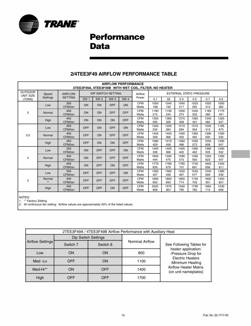
2/4TEE3F49 AIRFLOW PERFORMANCE TABLE
AIRFLOW PERFORMANCE2TEE3F49A, 4TEE3F49B WITH WET COIL, FILTER, NO HEATER
OUTDOORUNIT SIZE
(TONS)
SpeedSettings
AIRFLOWSETTING
DIP SWITCH SETTING AirflowPower
EXTERNAL STATIC PRESSURE
SW 1 SW 2 SW 3 SW 4 0.1 .02 0.3 0.5 0.7 0.9
3
Low350
CFM/tonON ON OFF ON
CFMWatts
1050168
1045192
1040217
1025265
1005313
1000362
Normal400
CFM/tonON ON OFF OFF
CFMWatts
1190215
1195245
1200274
1200333
1185392
1175451
High450
CFM/tonON ON ON OFF
CFMWatts
1355295
1360326
1370358
1365421
1345484
1325547
3.5
Low350
CFM/tonOFF ON OFF ON
CFMWatts
1200234
1205264
1215294
1210354
1205413
1185473
Normal400
CFM/tonOFF ON OFF OFF
CFMWatts
1405326
1405366
1405402
1395462
1390505
1290532
High450
CFM/tonOFF ON ON OFF
CFMWatts
1580429
1570458
1560496
1555573
1550608
1390547
4
Low350
CFM/tonON OFF OFF ON
CFMWatts
1405326
1405366
1405402
1395462
1390505
1290532
Normal400
CFM/tonON OFF OFF OFF
CFMWatts
1600444
1595475
1585515
1590593
1555623
1390547
High450
CFM/tonON OFF ON OFF
CFMWatts
1775635
1780679
1785701
1740697
1600656
1450611
5
Low350
CFM/tonOFF OFF OFF ON
CFMWatts
1565427
1560458
1550497
1545577
1540609
1380539
Normal**
400CFM/ton
OFF OFF OFF OFFCFMWatts
1800652
1800693
1800714
1740703
1600651
1450621
High450
CFM/tonOFF OFF ON OFF
CFMWatts
2020808
1975801
1930790
1795760
1665715
1530658
NOTES: 1. ** Factory Setting 2. At continuous fan setting: Airflow values are approximately 50% of the listed values.
2TEE3F49A / 4TEE3F49B Airflow Performance with Auxiliary Heat
Airflow SettingsDip Switch Settings
Nominal AirflowSee Following Tables for
heater application:-Pressure Drop for
Electric Heaters-Minimum Heating
Airflow Heater Matrix(on unit nameplates)
Switch 7 Switch 8
Low ON ON 800
Med -Lo OFF ON 1100
Med-Hi** ON OFF 1400
High OFF OFF 1700

Pub. No. 22-1717-05 13
2/4TEE3F64 AIRFLOW PERFORMANCE TABLE
AIRFLOW PERFORMANCE2/4TEE64A1 WITH WET COIL, FILTER, NO HEATER
OUTDOORUNIT SIZE
(TONS)
SpeedSettings
AIRFLOWSETTING
DIP SWITCH SETTING AirflowPower
EXTERNAL STATIC PRESSURE
SW 1 SW 2 SW 3 SW 4 0.1 0.3 0.5 0.7 0.9
3 tons
Low350
CFM/tonON ON OFF ON
CFMWatts
1192191
1222256
1226315
1213370
1185420
Normal400
CFM/tonON ON OFF OFF
CFMWatts
1380269
1382329
1388396
1402472
1381531
High450
CFM/tonON ON ON OFF
CFMWatts
1532348
1564433
1580513
1583590
1591679
3.5 tons
Low350
CFM/tonOFF ON OFF ON
CFMWatts
1389272
1385332
1396400
1409473
1387532
Normal400
CFM/tonOFF ON OFF OFF
CFMWatts
1605394
1630482
1643564
1636633
1636712
High450
CFM/tonOFF ON ON OFF
CFMWatts
1831563
1846651
1845731
1793769
1619692
4 tons
Low350
CFM/tonON OFF OFF ON
CFMWatts
1588385
1624477
1632555
1626626
1627701
Normal400
CFM/tonON OFF OFF OFF
CFMWatts
1862591
1879685
1869754
1783762
1622698
High450
CFM/tonON OFF ON OFF
CFMWatts
2081811
2052863
1956845
1827806
1699764
5 tons
Low350
CFM/tonOFF OFF OFF ON
CFMWatts
2002729
2005816
1948841
1806787
1718786
Normal**
400CFM/ton
OFF OFF OFF OFFCFMWatts
2225978
2116945
2010913
1904879
1765841
High450
CFM/tonOFF OFF ON OFF
CFMWatts
22811061
21801025
2074985
1956941
1838901
NOTES: 1. ** Factory Setting 2. At continuous fan setting: Airflow values are approximately 50% of the listed values
Airflow Performance with Auxiliary Heat
Airflow SettingsDip Switch Settings
Nominal AirflowSee Following Tables for
heater application:-Pressure Drop for
Electric Heaters-Minimum Heating
Airflow Heater Matrix(on unit nameplates)
Switch 7 Switch 8
Low ON ON 900
Med -Lo OFF ON 1200
Med-Hi ON OFF 1500
High OFF OFF 1800
14 Pub. No. 22-1717-05
PerformanceData
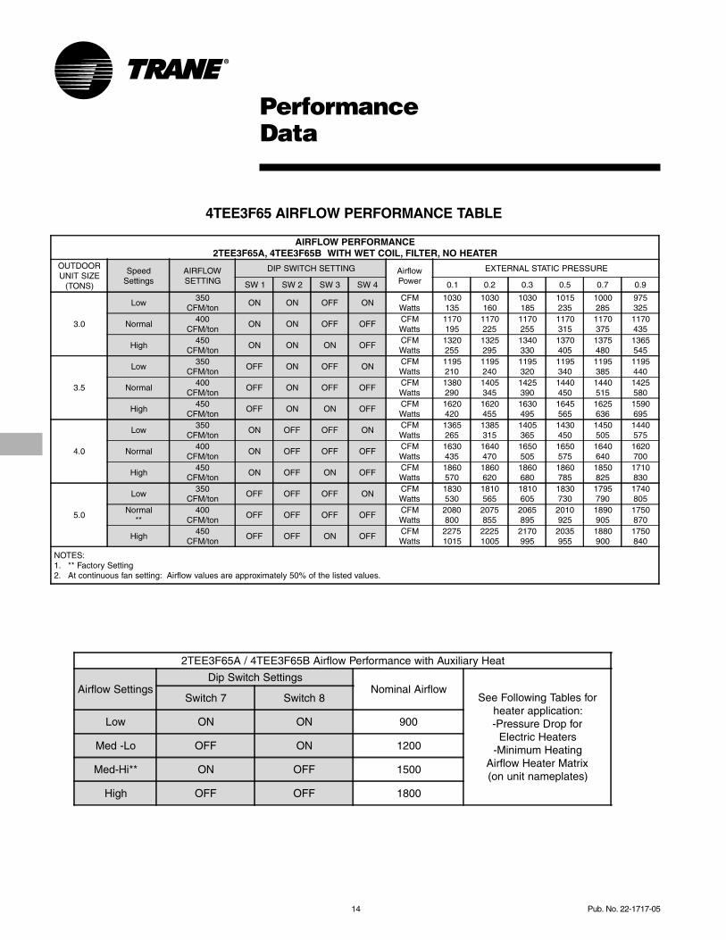
4TEE3F65 AIRFLOW PERFORMANCE TABLE
AIRFLOW PERFORMANCE2TEE3F65A, 4TEE3F65B WITH WET COIL, FILTER, NO HEATER
OUTDOORUNIT SIZE
(TONS)
SpeedSettings
AIRFLOWSETTING
DIP SWITCH SETTING AirflowPower
EXTERNAL STATIC PRESSURE
SW 1 SW 2 SW 3 SW 4 0.1 0.2 0.3 0.5 0.7 0.9
3.0
Low350
CFM/tonON ON OFF ON
CFMWatts
1030135
1030160
1030185
1015235
1000285
975325
Normal400
CFM/tonON ON OFF OFF
CFMWatts
1170195
1170225
1170255
1170315
1170375
1170435
High450
CFM/tonON ON ON OFF
CFMWatts
1320255
1325295
1340330
1370405
1375480
1365545
3.5
Low350
CFM/tonOFF ON OFF ON
CFMWatts
1195210
1195240
1195320
1195340
1195385
1195440
Normal400
CFM/tonOFF ON OFF OFF
CFMWatts
1380290
1405345
1425390
1440450
1440515
1425580
High450
CFM/tonOFF ON ON OFF
CFMWatts
1620420
1620455
1630495
1645565
1625636
1590695
4.0
Low350
CFM/tonON OFF OFF ON
CFMWatts
1365265
1385315
1405365
1430450
1450505
1440575
Normal400
CFM/tonON OFF OFF OFF
CFMWatts
1630435
1640470
1650505
1650575
1640640
1620700
High450
CFM/tonON OFF ON OFF
CFMWatts
1860570
1860620
1860680
1860785
1850825
1710830
5.0
Low350
CFM/tonOFF OFF OFF ON
CFMWatts
1830530
1810565
1810605
1830730
1795790
1740805
Normal**
400CFM/ton
OFF OFF OFF OFFCFMWatts
2080800
2075855
2065895
2010925
1890905
1750870
High450
CFM/tonOFF OFF ON OFF
CFMWatts
22751015
22251005
2170995
2035955
1880900
1750840
NOTES: 1. ** Factory Setting 2. At continuous fan setting: Airflow values are approximately 50% of the listed values.
2TEE3F65A / 4TEE3F65B Airflow Performance with Auxiliary Heat
Airflow SettingsDip Switch Settings
Nominal AirflowSee Following Tables for
heater application:-Pressure Drop for
Electric Heaters-Minimum Heating
Airflow Heater Matrix(on unit nameplates)
Switch 7 Switch 8
Low ON ON 900
Med -Lo OFF ON 1200
Med-Hi** ON OFF 1500
High OFF OFF 1800
Pub. No. 22-1717-05 15
PerformanceData
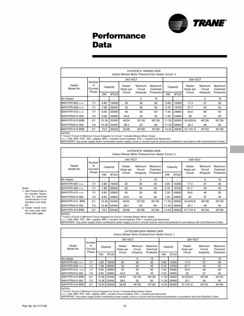
2/4TEE3F31 WIRING DATA(Indoor Blower Motor Powered from Heater Circuit 1)
HeaterModel No.
Numberof
Circuits/Phase
240 VOLT 208 VOLT
Capacity HeaterAmps per
Circuit
MinimumCircuit
Ampacity
MaximumOverloadProtection
Capacity HeaterAmps per
Circuit
MinimumCircuit
Ampacity
MaximumOverloadProtection
KW BTUH KW BTUH
No Heater - - - - 5 15 - - - 5 15
BAYHTR1405 +++ 1/1 4.80 16400 20 30 30 3.60 12300 17.3 27 30
BAYHTR1408 +++ 1/1 7.68 26200 32 45 45 5.76 19700 27.7 40 40
BAYHTR1410 +++ 1/1 9.60 32800 40 55 60 7.20 24600 34.6 49 50
BAYHTR3410 000 1/3 9.60 32800 34.6 43 45 7.20 24600 30 37 40
BAYHTR1415 BRK 2/1 15.36 52400 40/24 55*/30 60*/30 11.53 39300 34.6/20.8 49*/26 50*/30
BAYHTR3415 000 1/3 15.36 52400 38.2 52 60 11.53 39300 33.1 46 50
BAYHTR1419 BRK 2/1 19.2 65500 32/48 45*/60 45*/60 14.42 49200 27.7/41.6 40*/52 40*/60
NOTES:* Circuit 1/Circuit 2 (Minimum Circuit Ampacity for Circuit 1 includes Blower Motor Amps)+++ = 000, BRK, PDC 000 = pigtails, BRK = contains circuit breakers, PDC = contains pull disconnectIMPORTANT: Any power supply and/or combination power supply, circuit or circuits must be wired and protected in accordance with local Electrical Codes.
2/4TEE3F37 WIRING DATA(Indoor Blower Motor Powered from Heater Circuit 1)
HeaterModel No.
Numberof
Circuits/Phase
240 VOLT 208 VOLT
Capacity HeaterAmps per
Circuit
MinimumCircuit
Ampacity
MaximumOverloadProtection
Capacity HeaterAmps per
Circuit
MinimumCircuit
Ampacity
MaximumOverloadProtection
KW BTUH KW BTUH
No Heater - - - - 5 15 - - - 5 15
BAYHTR1405 +++ 1/1 4.80 16400 20 30 30 3.60 12300 17.3 27 30
BAYHTR1408 +++ 1/1 7.68 26200 32 45 45 5.76 19700 27.7 40 40
BAYHTR1410 +++ 1/1 9.60 32800 40 55 60 7.20 24600 34.6 49 50
BAYHTR3410 000 1/3 9.60 32800 34.6 43 45 7.20 24600 30 37 40
BAYHTR1415 BRK 2/1 15.36 52400 40/24 55*/30 60*/30 11.53 39300 34.6/20.8 49*/26 50*/30
BAYHTR3415 000 1/3 15.36 52400 38.2 52 60 11.53 39300 33.1 46 50
BAYHTR1419 BRK 2/1 19.2 65500 32/48 45*/60 45*/60 14.42 49200 27.7/41.6 40*/52 40*/60
NOTES:* Circuit 1/Circuit 2 (Minimum Circuit Ampacity for Circuit 1 includes Blower Motor Amps)+++ = 000, BRK, PDC 000 = pigtails, BRK = contains circuit breakers, PDC = contains pull disconnectIMPORTANT: Any power supply and/or combination power supply, circuit or circuits must be wired and protected in accordance with local Electrical Codes.
2/4TEE39A1000A WIRING DATA(Indoor Blower Motor Powered from Heater Circuit *)
HeaterModel No.
Numberof
Circuits/Phase
240 VOLT 208 VOLT
Capacity HeaterAmps per
Circuit
MinimumCircuit
Ampacity
MaximumOverloadProtection
Capacity HeaterAmps per
Circuit
MinimumCircuit
Ampacity
MaximumOverloadProtection
KW BTUH KW BTUH
No Heater - - - - 5 15 - - - 5 15 BAYHTR1405 +++ 1/1 4.80 16400 20 30 30 3.60 12300 17.3 27 30 BAYHTR1408 +++ 1/1 7.68 26200 32 45 45 5.76 19700 27.7 40 40 BAYHTR1410 +++ 1/1 9.60 32800 40 55 60 7.20 24600 34.6 49 50 BAYHTR3410 000 1/3 9.60 32800 34.6 43 45 7.20 24600 30 37 40 BAYHTR1415 BRK 2/1 15.36 52400 40/24 55*/30 60*/30 11.52 39300 34.6/20.8 49*/26 50*/30 BAYHTR3415 000 1/3 15.36 52400 38.2 52 60 11.52 39300 33.1 46 50
BAYHTR1419 BRK 2/1 19.20 65500 32/48 45*/60 45*/60 14.42 49200 27.7/41.6 40*/52 40*/60
NOTES: * Circuit 1/Circuit 2 (Minimum Circuit Ampacity for Circuit 1 includes Blower Motor Amps) +++ = 000, BRK, PDC 000 = pigtails, BRK = contains circuit breakers, PDC = contains pull disconnect IMPORTANT: Any power supply and/or combination power supply, circuit or circuits must be wired and protected in accordance with local Electrical Codes.
Notes:1. See Product Data or
Air Handler Name-plate for approvedcombinations of AirHandlers and Heat-ers.
2. Heater model num-ber may have addi-tional suffix digits.
16 Pub. No. 22-1717-05
PerformanceData
Notes:1. See Product Data or
Air Handler Name-plate for approvedcombinations of AirHandlers and Heat-ers.
2. Heater model numbermay have additionalsuffix digits.
2/4TEE3F49 WIRING DATA CHECK DATA(Indoor Blower Motor Powered from Heater Circuit *)
HeaterModel No.
Numberof
Circuits/Phase
240 VOLT 208 VOLT
Capacity HeaterAmps per
Circuit
MinimumCircuit
Ampacity
MaximumOverloadProtection
Capacity HeaterAmps per
Circuit
MinimumCircuit
Ampacity
MaximumOverloadProtection
KW BTUH KW BTUH
No Heater - - - - 9 15 - - - 9 15
BAYHTR1405 +++ 1/1 4.80 16400 20 34 40 3.60 12300 17.3 30 30
BAYHTR1408 +++ 1/1 7.68 26200 32 49 50 5.76 19700 27.7 43 45
BAYHTR1410 +++ 1/1 9.60 32800 40 59 60 7.20 24600 34.6 52 60BAYHTR3410 000 1/3 9.60 32800 34.6 43 45 7.20 24600 30 37 40BAYHTR1415 BRK 2/1 15.36 52400 40/24 59*/30 60*/30 11.53 39300 34.6/20.8 52*/26 60*/30BAYHTR3415 000 1/3 15.36 52400 38.2 55 60 11.53 39300 33.1 49 50
BAYHTR1419 BRK 2/1 19.2 65500 32/48 49*/60 50*/60 14.42 49200 27.7/41.6 43*/52 45*/60
BAYHTR1425 BRK 3/1 24.96 85200 44/40/20 55/59*/25 60/60*/25 18.73 63900 38.1/34.6/17.3 48/50*/22 50/60*/25
NOTES:* Circuit 1/Circuit 2 (Minimum Circuit Ampacity for Circuit 1 includes Blower Motor Amps)+++ = 000, BRK, PDC 000 = pigtails, BRK = contains circuit breakers, PDC = contains pull disconnectIMPORTANT: Any power supply and/or combination power supply, circuit or circuits must be wired and protected in accordance with local Electrical Codes.
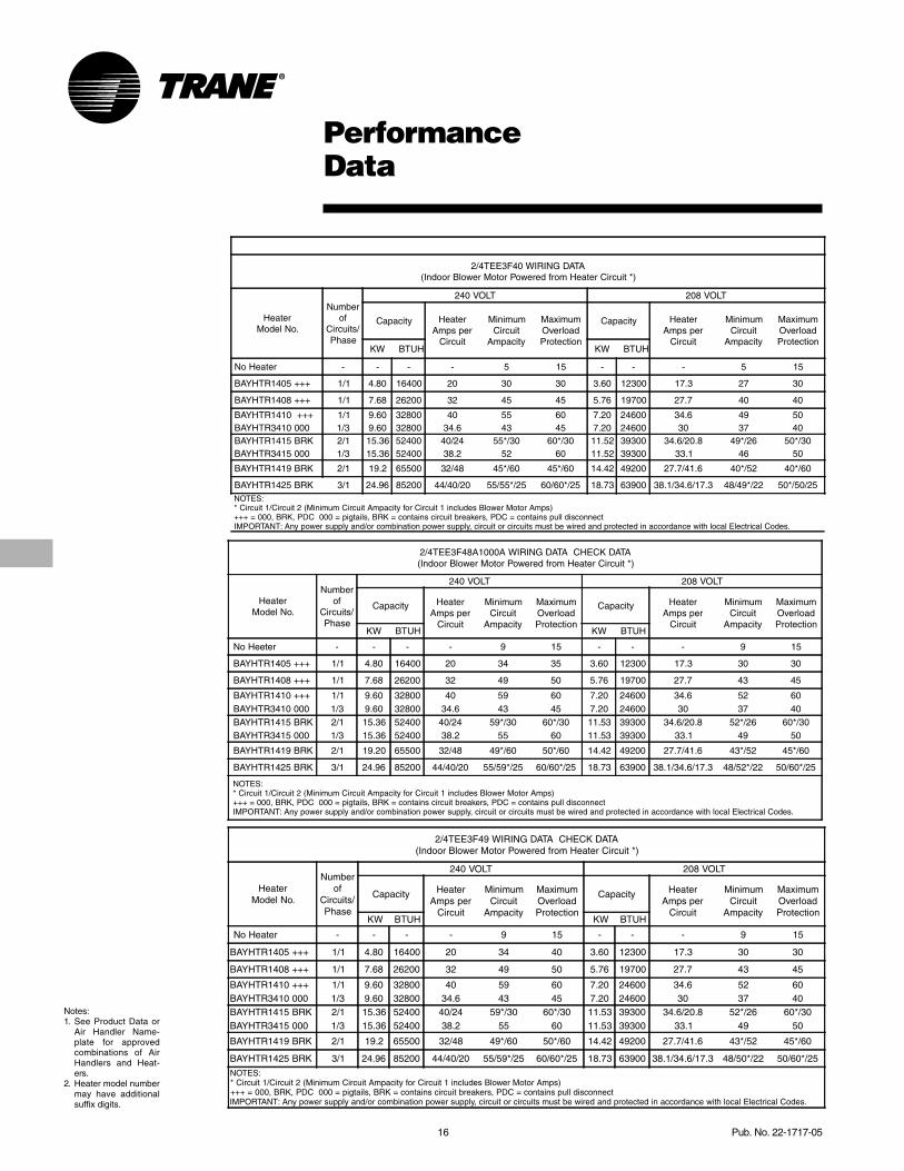
2/4TEE3F40 WIRING DATA(Indoor Blower Motor Powered from Heater Circuit *)
HeaterModel No.
Numberof
Circuits/Phase
240 VOLT 208 VOLT
Capacity HeaterAmps per
Circuit
MinimumCircuit
Ampacity
MaximumOverloadProtection
Capacity HeaterAmps per
Circuit
MinimumCircuit
Ampacity
MaximumOverloadProtection
KW BTUH KW BTUH
No Heater - - - - 5 15 - - - 5 15
BAYHTR1405 +++ 1/1 4.80 16400 20 30 30 3.60 12300 17.3 27 30
BAYHTR1408 +++ 1/1 7.68 26200 32 45 45 5.76 19700 27.7 40 40
BAYHTR1410 +++ 1/1 9.60 32800 40 55 60 7.20 24600 34.6 49 50 BAYHTR3410 000 1/3 9.60 32800 34.6 43 45 7.20 24600 30 37 40 BAYHTR1415 BRK 2/1 15.36 52400 40/24 55*/30 60*/30 11.52 39300 34.6/20.8 49*/26 50*/30 BAYHTR3415 000 1/3 15.36 52400 38.2 52 60 11.52 39300 33.1 46 50
BAYHTR1419 BRK 2/1 19.2 65500 32/48 45*/60 45*/60 14.42 49200 27.7/41.6 40*/52 40*/60
BAYHTR1425 BRK 3/1 24.96 85200 44/40/20 55/55*/25 60/60*/25 18.73 63900 38.1/34.6/17.3 48/49*/22 50*/50/25 NOTES: * Circuit 1/Circuit 2 (Minimum Circuit Ampacity for Circuit 1 includes Blower Motor Amps) +++ = 000, BRK, PDC 000 = pigtails, BRK = contains circuit breakers, PDC = contains pull disconnect IMPORTANT: Any power supply and/or combination power supply, circuit or circuits must be wired and protected in accordance with local Electrical Codes.
2/4TEE3F48A1000A WIRING DATA CHECK DATA(Indoor Blower Motor Powered from Heater Circuit *)
HeaterModel No.
Numberof
Circuits/Phase
240 VOLT 208 VOLT
Capacity HeaterAmps per
Circuit
MinimumCircuit
Ampacity
MaximumOverloadProtection
Capacity HeaterAmps per
Circuit
MinimumCircuit
Ampacity
MaximumOverloadProtection
KW BTUH KW BTUH
No Heeter - - - - 9 15 - - - 9 15
BAYHTR1405 +++ 1/1 4.80 16400 20 34 35 3.60 12300 17.3 30 30
BAYHTR1408 +++ 1/1 7.68 26200 32 49 50 5.76 19700 27.7 43 45
BAYHTR1410 +++ 1/1 9.60 32800 40 59 60 7.20 24600 34.6 52 60 BAYHTR3410 000 1/3 9.60 32800 34.6 43 45 7.20 24600 30 37 40 BAYHTR1415 BRK 2/1 15.36 52400 40/24 59*/30 60*/30 11.53 39300 34.6/20.8 52*/26 60*/30 BAYHTR3415 000 1/3 15.36 52400 38.2 55 60 11.53 39300 33.1 49 50
BAYHTR1419 BRK 2/1 19.20 65500 32/48 49*/60 50*/60 14.42 49200 27.7/41.6 43*/52 45*/60
BAYHTR1425 BRK 3/1 24.96 85200 44/40/20 55/59*/25 60/60*/25 18.73 63900 38.1/34.6/17.3 48/52*/22 50/60*/25
NOTES: * Circuit 1/Circuit 2 (Minimum Circuit Ampacity for Circuit 1 includes Blower Motor Amps) +++ = 000, BRK, PDC 000 = pigtails, BRK = contains circuit breakers, PDC = contains pull disconnect IMPORTANT: Any power supply and/or combination power supply, circuit or circuits must be wired and protected in accordance with local Electrical Codes.
Pub. No. 22-1717-05 17
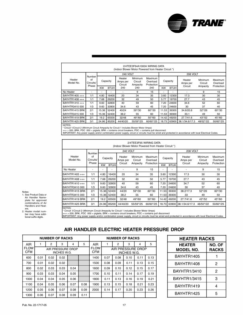
AIR HANDLER ELECTRIC HEATER PRESSURE DROP
2/4TEE3F65 WIRING DATA(Indoor Blower Motor Powered from Heater Circuit *)
HeaterModel No.
Numberof
Circuits/Phase
240 VOLT 208 VOLT
Capacity HeaterAmps per
Circuit
MinimumCircuit
Ampacity
MaximumOverloadProtection
Capacity HeaterAmps per
Circuit
MinimumCircuit
Ampacity
MaximumOverloadProtection
KW BTUH KW BTUH
No Heater - - - - 9 15 - - - 9 15
BAYHTR1405 +++ 1/1 4.80 16400 20 34 35 3.60 12300 17.3 30 30
BAYHTR1408 +++ 1/1 7.68 26200 32 49 50 5.77 19700 27.7 43 45
BAYHTR1410 +++ 1/1 9.60 32800 40 59 60 7.20 24600 34.7 52 60BAYHTR3410 000 1/3 9.60 32800 34.6 43 45 7.20 24600 30 37 40BAYHTR1415 BRK 2/1 15.36 52400 44/20 59*/30 60*/30 11.53 39300 38.2/17.3 52*/26 60*/30BAYHTR3415 000 1/3 15.36 52400 38.2 55 60 11.53 39300 33 49 50
BAYHTR1419 BRK 2/1 19.2 65500 32/48 49*/60 50*/60 14.42 49200 27.7/41.6 43*/52 45*/60
BAYHTR1425 BRK 3/1 24.96 85200 44/40/20 55/59*/25 60/60*/25 18.73 63900 38.1/34.6/17.3 48/50*/22 50/60*/25
NOTES:* Circuit 1/Circuit 2 (Minimum Circuit Ampacity for Circuit 1 includes Blower Motor Amps)+++ = 000, BRK, PDC 000 = pigtails, BRK = contains circuit breakers, PDC = contains pull disconnectIMPORTANT: Any power supply and/or combination power supply, circuit or circuits must be wired and protected in accordance with local Electrical Codes.
HEATER RACKSHEATER
MODEL NO.NO. OFRACKS
BAYHTR1405 1
BAYHTR1408 2
BAYHTR1/3410 2
BAYHTR1/3415 3
BAYHTR1419 4
BAYHTR1425 5
NUMBER OF RACKS NUMBER OF RACKS
AIRFLOWCFM
1 2 3 4 5 AIRFLOWCFM
1 2 3 4 5
AIR PRESSURE DROPINCHES W.G.
AIR PRESSURE DROPINCHES W.G.
600 0.01 0.02 0.02 1400 0.07 0.08 0.10 0.11 0.13
700 0.01 0.02 0.02 1500 0.08 0.09 0.11 0.13 0.15
800 0.02 0.03 0.03 0.04 1600 0.09 0.10 0.12 0.15 0.17
900 0.03 0.03 0.04 0.05 1700 0.10 0.11 0.14 0.17 0.19
1000 0.04 0.04 0.05 0.06 1800 0.11 0.13 0.16 0.19 0.21
1100 0.04 0.05 0.06 0.07 0.08 1900 0.13 0.15 0.18 0.21 0.23
1200 0.05 0.06 0.07 0.08 0.09 2000 0.14 0.17 0.20 0.23 0.26
1300 0.06 0.07 0.08 0.09 0.11
2/4TEE3F64A1000A WIRING DATA(Indoor Blower Motor Powered from Heater Circuit *)
HeaterModel No.
Numberof
Circuits/Phase
240 VOLT 208 VOLT
CapacityHeater
Amps perCircuit
240
MinimumCircuit
Ampacity240
MaximumOverloadProtection
240
Capacity HeaterAmps per
Circuit
MinimumCircuit
Ampacity
MaximumOverloadProtection
KW BTUH KW BTUH
No Heater - - - - 9 15 - - - 9 15 BAYHTR1405 +++ 1/1 4.80 16400 20 34 35 3.60 12300 17.3 30 30 BAYHTR1408 +++ 1/1 7.68 26200 32 49 50 5.77 19700 27.7 43 45 BAYHTR1410 +++ 1/1 9.60 32800 40 59 60 7.20 24600 34.6 52 60 BAYHTR3410 000 1/3 9.60 32800 34.6 43 45 7.20 24600 30 37 40 BAYHTR1415 BRK 2/1 15.36 52400 40/24 59*/30 60*/30 11.53 39300 34.6/20.8 52*/26 60*/30 BAYHTR3415 000 1/3 15.36 52400 38.2 55 60 11.53 39300 33.1 49 50 BAYHTR1419 BRK 2/1 19.2 65500 32/48 49*/60 50*/60 14.42 49200 27.7/41.6 43*/52 45*/60 BAYHTR1425 BRK 3/1 24.96 85200 44/40/20 55/59*/25 60/60*/25 18.73 63900 38.1/34.6/17.3 48/52*/22 50/60*/25 NOTES: * Circuit 1/Circuit 2 (Minimum Circuit Ampacity for Circuit 1 includes Blower Motor Amps) +++ = 000, BRK, PDC 000 = pigtails, BRK = contains circuit breakers, PDC = contains pull disconnect IMPORTANT: Any power supply and/or combination power supply, circuit or circuits must be wired and protected in accordance with local Electrical Codes.
Notes:1. See Product Data or
Air Handler Name-plate for approvedcombinations of AirHandlers and Heat-ers.
2. Heater model num-ber may have addi-tional suffix digits.
18 Pub. No. 22-1717-05
PerformanceData
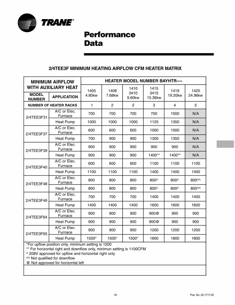
2/4TEE3F MINIMUM HEATING AIRFLOW CFM HEATER MATRIX
MINIMUM AIRFLOWWITH AUXILIARY HEAT
HEATER MODEL NUMBER BAYHTR----
14054.80kw
14087.68kw
14103410
9.60kw
14153415
15.36kw
141919.20kw
142524.96kwMODEL
NUMBERAPPLICATION
NUMBER OF HEATER RACKS 1 2 2 3 4 5
2/4TEE3F31
A/C or Elec.Furnace
700 700 700 700 1000 N/A
Heat Pump 1000 1000 1000 1125 1350 N/A
2/4TEE3F37
A/C or Elec.Furnace
600 600 600 1000 1000 N/A
Heat Pump 700 900 900 1300 1350 N/A
2/4TEE3F39
A/C or Elec.Furnace
900 900 900 900 900 N/A
Heat Pump 900 900 900 1400** 1400** N/A
2/4TEE3F40
A/C or Elec.Furnace
600 600 600 1100 1100 1100
Heat Pump 1100 1100 1100 1400 1400 1400
2/4TEE3F48
A/C or Elec.Furnace
800 800 800 800^ 800^ 800^^
Heat Pump 800 800 800 800^ 800^ 800^^
2/4TEE3F49
A/C or Elec.Furnace
700 700 700 1400 1400 1400
Heat Pump 1400 1400 1400 1600 1600 1600
2/4TEE3F64
A/C or Elec.Furnace
900 900 900 900@ 900 900
Heat Pump 900 900 900 900@ 900 900
2/4TEE3F65
A/C or Elec.Furnace
900 900 900 1200 1200 1200
Heat Pump 1500* 1500* 1500* 1800 1800 1800
*For upflow position only, minimum setting is 1200 ** For horizontal right and downflow only, minimun setting is 1100CFM ^ 208V approved for upflow and horizontal right only ^^ Not qualified for downflow @ Not approved for horizontal left
Pub. No. 22-1717-05 19
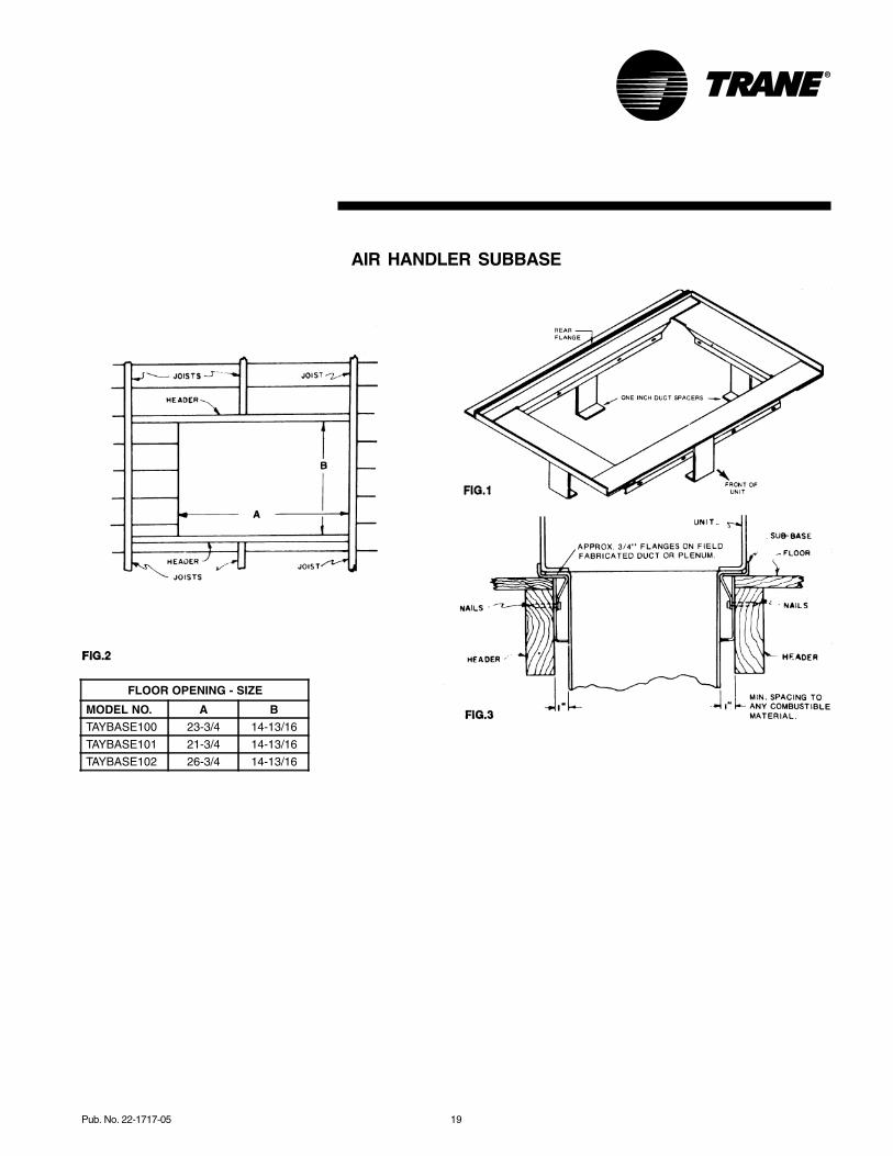
AIR HANDLER SUBBASE
FLOOR OPENING - SIZE
MODEL NO. A B TAYBASE100 23-3/4 14-13/16
TAYBASE101 21-3/4 14-13/16
TAYBASE102 26-3/4 14-13/16
20 Pub. No. 22-1717-05
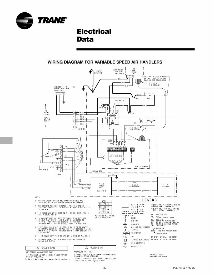
ElectricalData
WIRING DIAGRAM FOR VARIABLE SPEED AIR HANDLERS

Pub. No. 22-1717-05 21
FieldWiring
From Dwg. 21D800255 Rev. 0
From Dwg. 21D800254 Rev. 0
2/4TEE3F AIR HANDLERS WITH SINGLE SPEED COOLING
2/4TEE3F AIR HANDLERS WITH SINGLE SPEED HEAT PUMP
NOTES:1. POWER WIRING AND GROUNDING OF EQUIPMENT MUST COMPLY WITH LOCAL CODES.
2. BE SURE POWER SUPPLY AGREES WITH EQUIPMENT NAMEPLATE.
3. LOW VOLTAGE WIRING TO BE NO. 18 A.W.G. MINIMUM.
4. USE COPPER CONDUCTORS ONLY.
5. POLARIZED PLUG SECTION PM-A IS ATTACHED TO HEATER CONTROL BOX. SECTION I-PF IS FACTORY WIRED INTO AIR HANDLER.
6. TERMINAL W2 WILL HAVE INTERNAL CONNECTIONS ONLY IF SECOND CONTACTOR IS USED BY THE HEATER FOR CONTROLLING POWER TO ELECTRIC HEATING ELEMENTS. IF SECOND (BH) CONTACTOR IS NOT USED, THEN FIELD CONNECTIONS TO W2 CAN BE OMITTED AS APPROPRIATE.
7. CONNECTIONS TO "R", "BK", "O", AND "Y" MUST BE MADE AS SHOWN FOR PROPER OPERATION OF BLOWER WITH HUMIDISTAT IN COOLING.
D800254
NOTES:1. POWER WIRING AND GROUNDING OF EQUIPMENT MUST COMPLY WITH LOCAL CODES.
2. BE SURE POWER SUPPLY AGREES WITH EQUIPMENT NAMEPLATE.
3. LOW VOLTAGE WIRING TO BE NO. 18 A.W.G. MINIMUM.
4. USE COPPER CONDUCTORS ONLY.
5. POLARIZED PLUG SECTION PM-A IS ATTACHED TO HEATER CONTROL BOX. SECTION I-PF IS FACTORY WIRED INTO AIR HANDLER.
6. TERMINAL W2 WILL HAVE INTERNAL CONNECTIONS ONLY IF SECOND CONTACTOR IS USED BY THE HEATER FOR CONTROLLING POWER TO ELECTRIC HEATING ELEMENTS. IF SECOND (BH) CONTACTOR IS NOT USED, THEN FIELD CONNECTIONS TO W2 CAN BE OMITTED AS APPROPRIATE.
7. IF ODT IS NOT USED, THEN CONNECT APPROPIATE JUMPER FROM W1 TO W2 ON LVTB.
8. IF OPTIONAL HUMIDISTAT IS USED, REMOVE JUMPER (R-BK) AND INSTALL HUMIDISTAT BETWEEN "R" AND "BK".
9. CONNECT IN THIS MANNER IF O. D. UNIT HAS "F" CONNECTION.
10. CONNECT W3 TO W2 ONLY IF USING HEATER WITH 3 HEATER STAGES.
D800255

22 Pub. No. 22-1717-05
2/4TEE3F31 Through 65Convertibility
SIX (6) WAY CONVERTIBILITY
Primary Condensate
Horizontal Drain pan
Refrigerant Connections
Coil Supports
Airflow
One Unit - 4 Applications(Conversions 1-4)
Airflow
Vertical Upflow (as shipped)
One-step Conversion Stand unit on end
Horizontal LeftRotate Coil
Airflow
Vertical Downflow One-step Conversion
from Horizontal left
AirflowAirflow
Airflow
Airflow
Airflow
Easy Conversion to Opposite side Access(Conversions 5 & 6)
1 Unit is shipped asHorizontal right
2 Pull coil out androtate the coil 180˚
Slide coil back in onsupports and roll unit180˚ (so primarycondensate is down)
3
Note connections and access are nowon back side of unit
4
Horizontal Right(as shipped)
6 CONVERSION APPLICATIONS1. Horizontal Right - (Front Access)2. Vertical Upflow3. Horizontal Left - (Front Access)4. Vertical Downflow5. Horizontal Right - (Rear Access)6. Horizontal Left - (Rear Access)
Pub. No. 22-1717-05 23
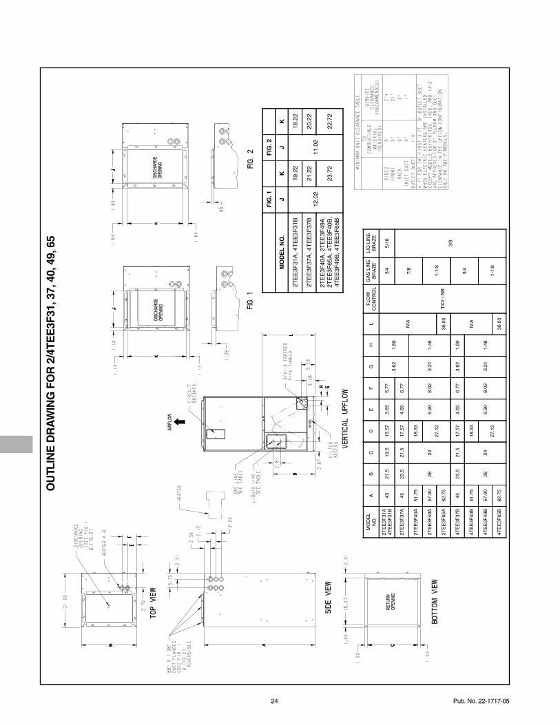
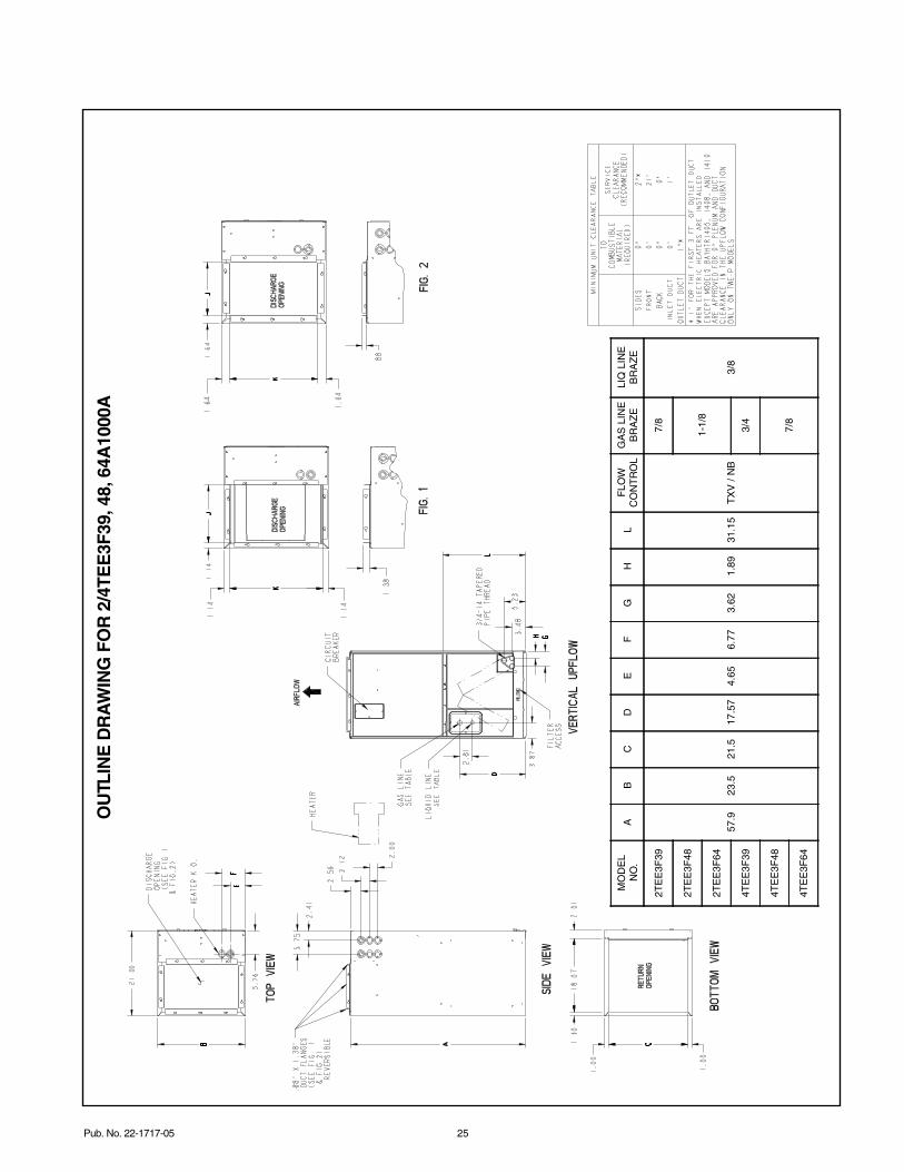
Dimensions
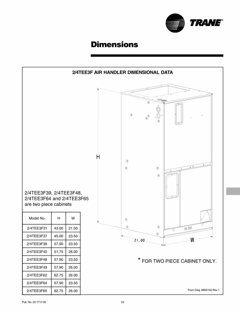
2/4TEE3F AIR HANDLER DIMENSIONAL DATA
From Dwg. B802150 Rev 1
Model No. H W
2/4TEE3F31 43.00 21.50
2/4TEE3F37 45.00 23.50
2/4TEE3F39 57.90 23.50
2/4TEE3F40 51.75 26.00
2/4TEE3F48 57.90 23.50
2/4TEE3F49 57.90 26.00
2/4TEE3F62 62.75 26.00
2/4TEE3F64 57.90 23.50
2/4TEE3F65 62.75 26.00
* FOR TWO PIECE CABINET ONLY.
2/4TEE3F39, 2/4TEE3F48,2/4TEE3F64 and 2/4TEE3F65are two piece cabinets
24 Pub. No. 22-1717-05
MO
DE
LN
O.
AB
CD
EF
GH
LF
LOW
CO
NT
RO
LG
AS
LIN
EB
RA
ZE
LIQ
LIN
EB
RA
ZE
2TE
E3F
31A
4TE
E3F
31B
4321
.519
.515
.57
3.65
5.77
3.62
1.89
N/A
TX
V /
NB
3/4
5/16
2TE
E3F
37A
4523
.521
.517
.57
4.65
6.77
7/8
3/8
2TE
E3F
40A
51.7
5
2624
18.3
3
5.90
8.02
3.21
1.48
2TE
E3F
49A
57.9
027
.12
1-1/
82T
EE
3F65
A62
.75
36.0
0
4TE
E3F
37B
4523
.521
.517
.57
4.65
6.77
3.62
1.89
N/A
3/4
4TE
E3F
40B
51.7
5
2624
18.3
3
5.90
8.02
3.21
1.48
4TE
E3F
49B
57.9
027
.12
1-1/
84T
EE
3F65
B62
.75
36.0
0
FIG
. 1F
IG. 2
MO
DE
L N
O.
JK
JK
2TE
E3F
31A
, 4T
EE
3F31
B
12.0
2
19.2
2
11.0
2
18.2
2
2TE
E3F
37A
, 4T
EE
3F37
B21
.22
20.2
2
2TE
E3F
40A
, 2T
EE
3F49
A.
2TE
E3F
65A
, 4T
EE
3F40
B,
4TE
E3F
49B
, 4T
EE
3F65
B23
.72
22.7
2
OU
TLIN
E D
RA
WIN
G F
OR
2/4
TEE
3F31
, 37,
40,
49,
65
Pub. No. 22-1717-05 25
MO
DE
LN
O.
AB
CD
EF
GH
LF
LOW
CO
NT
RO
LG
AS
LIN
EB
RA
ZE
LIQ
LIN
EB
RA
ZE
2TE
E3F
39
57.9
23.5
21.5
17.5
74.
656.
773.
621.
8931
.15
TX
V /
NB
7/8
3/8
2TE
E3F
481-
1/8
2TE
E3F
64
4TE
E3F
393/
4
4TE
E3F
487/
84T
EE
3F64
OU
TLIN
E D
RA
WIN
G F
OR
2/4
TEE
3F39
, 48,
64A
1000
A

Trane6200 Troup HighwayTyler, TX 75707www.trane.com
05/08
The manufacturer has a policy of continuous product and product data improvement and it reserves the rightto change design and specifications without notice.
MechanicalSpecification Options
Features and General InformationThese blower coil units are completely factoryassembled including coil, condensate drainpan, fan, motor, filters and controls in an insu-lated casing that can be applied in horizontalor vertical configuration. The “Air-Tite™”model has 4.2 “R” value insulation and addi-tional sealing systems. The 2/4TEE3F line ofair handlers provides exclusive compact sizecombined with 6-way convertibility in sizes upto 5 ton.
The 3.5, 4, and 5 ton TEE3F models areavailable in 26" widths or with VorticaTM
in 23.5" widths.
The unit ships in the vertical upflow configura-tion and converts to right-hand horizontalconfiguration just by laying the unit on its side.No tools required. Simple coil rotation pro-vides downflow and horizontal left applica-tions.
CasingThese models have a rugged galvanizedsheet metal and steel frame construction.The casing is painted with an enamel finish.The casing is insulated and provides knock-outs for electrical power and control wiring.
Refrigerant CircuitsThe 2/4TEE3F units have a single refrigerantcircuit. The refrigerant circuit is controlled bya factory installed non-bleed thermalexpansion valve (TXV).
CoilAluminum fin surface is mechanically bondedto 3/8-inch OD copper tubing. Coils are fac-tory pressure and leak tested.
FanThe blower housing is forward curved, dy-namically balanced with a variable speed di-rect drive fan motor. The fan motor is perma-nently lubricated.
ControlsLow voltage terminal board, fan contactor,and plug-in module for accessory electricheat control is included. 2/4TEE3F modelsalso have a check valve.
FiltersThe 2/4TEE3F31 through 2/4TEE3F65 havestandard size filters.
Electric HeatersHeaters for the 2/4TEE3F air handlers areavailable in a wide range of capacities andvoltages with various staging options, andplug-in control wiring. Heaters fit inside the in-ternal compartment.