Embed Size (px)
Citation preview

modular safety integrated controller
product catalogue
2
new
MAx Analog input expansion unit
MODULAR SAFETY INTEGRATED CONTROLLER
MBx Expansion units for connection to the most common industrial Fieldbus systems for diagnos-tics and data communication
USB Connection USB 2.0 serial bus for
the connection to Mo-saic Safety Designer
(MSD) software
Mosaic Configuration Memory (MCM) Removable memory card for saving Mosaic config-uration data for subse-quent transfers to a new device (without using a PC) or for backup
M1 (Standard) or M1S (Enhanced) Master Unit
The Master Unit can be used as a stand-alone device or to control other expansion units
Mosaic Safety Communi-cation (MSC) Allows communication between the various units through a proprietary high-speed safety bus
MIx, MOx Additional Input/Output units
MOR4, MOR4S8 Safety relay units with configurable outputs
MVx Expansion units for safety speed monitoring
Removable terminals Two versions available - with clamp contacts - with screw contacts

3MODULAR SAFETY INTEGRATED CONTROLLER
KEY FEATURES
Mosaic is a safety hub able to manage all safety functions of a machinery. Configurable and scalable, allows cost reductions and minimal wiring
Mosaic can manage safety sensors and signals such as:
- Light curtains
- Photocells
- Laser scanners
- Emergency stops
- Electromechanical switches
- Guard-lock safety door switches
- Magnetic switches
- RFID switches
- Inductive sensors
- Safety mats and edges
- Two-hands controls
- Hand grip switches
- Safety switch with guard locking
- Encoders and proximities for safety speed control
- Loading cells, pressure switches, temperature measurements, flow and level measurements
ADVANTAGES
Compared to “traditional” electromechanical safety-relays-based safety circuitries, Mosaic has the following advantages:
Reducing the number of devices and wiring used and, therefore, the overall size of the project
Speeding-up control panel construction
Providing logic configuration via a quick and easy-to-use software. Machine designers are always able to change configuration logic
Master units M1 and M1S configurable via the MSD (Mosaic Safety Designer) graphic interface (provided with each Master units at no extra cost)
Simply adding or removing safety function blocks at any stage of machine design
Is able to check the logic configuration of the application during the designing phase through the validation function and Simulation as well as to test it during the installation through the monitor function
Allows tamper-proof system configurations as:
- detection of tempering attempts through specific tests (i.e. mandatory test of the safety device at machine start-up)
- protection against unauthorized changes to the project through a 2-level password
All logic is configured through a graphic interface. No more laborious wiring is needed as with traditional solutions
A lower number of electromechanical components also means a better Performance Level and, therefore, a higher Safety Level
The project report provides the actual values of PFHd, DCavg and MTTFd according to EN 13849-1 and EN 62061
Up to
SAFETY LEVEL
SIL3 - SILCL 3PL e - Cat. 4
SIL 3
4 MODULAR SAFETY INTEGRATED CONTROLLER
Connect up to 14 expansions......to the Master Units
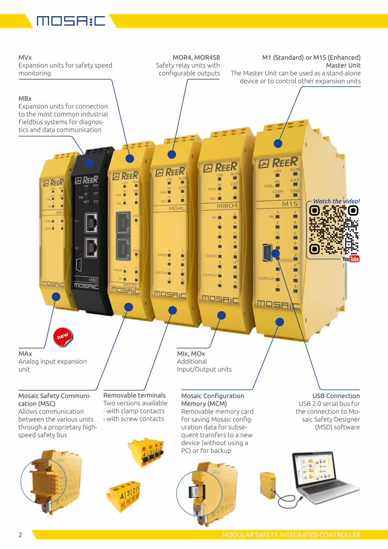
MVx
Speed monitoring expansion units
Safety speed monitoring (up to PL e) for: zero speed control, maximum speed control, speed range control, direction contol
MV0
Inputs for 2 proximity switches
MV1
Inputs for 1 incremental encoder and 2 proximity switches (TTL, HTL o SIN/COS)
MV2
Inputs for 2 incremental encoders and 2 proximity switches (TTL, HTL o SIN/COS)
Speed monitoring
MIx / MI12T8 / MAx
Input expansion units
MI8
8 digital inputs
4 test outputs (for short-circuits monitoring)
MI16
16 digital inputs
4 test outputs (for short-circuits monitoring)
MI12T8
12 digital inputs
8 test outputs (for short-circuits monitoring)
Can manage up to 4 independent safety mats/edges
MA2, MA4
2 (MA2) or 4 (MA4)4 indipendent isolated analogue channels (500 V)
Each channel can supply 24V DC up to 30 mA
Each channel can detect a 4-20 mA current or a 0-10V voltage (selectable via software)
MOx / MO4L HC S8 / MO4L
Output expansion units
MO2
2 pairs OSSD safety outputs (PNP 400 mA)
2 inputs for Start/Restart interlock and EDM
2 status outputs (PNP 100 mA)
MO4
4 pairs OSSD safety outputs (PNP 400 mA)
4 inputs for Start/Restart interlock and EDM
4 status outputs (PNP 100 mA)
MO4L HC S8 POWER
4 single OSSD safety outputs or 2 pairs (PNP 2,0 A for each channel, total current 8 A)
4 inputs for Start/Restart interlock and EDM
8 status outputs (PNP 100 mA)
MO4L
4 single OSSD safety outputs or 2 pairs (PNP 400 mA)
Up to 4 status outputs (PNP 100 mA). See note 1
4 status outputs (PNP 100 mA). See note 1
Additional inputs Additional outputs
2A2APOWER
M1
Standard Master Unit
8 digital inputs
2 inputs for Start/Restart interlock and EDM
2 pairs OSSD safety outputs (PNP 400 mA)
2 status outputs (PNP 100 mA)
4 test outputs (for short-circuits monitoring)
Not compatible with the following expansion units: MA2, MA4, MI8O4, MO4L
newnew
new
new
5MODULAR SAFETY INTEGRATED CONTROLLER
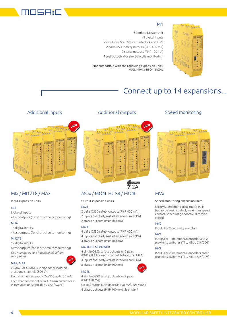
MI8Ox
Input/Output expansion units
MI8O2
8 digital inputs
2 inputs for Start/Restart inter-lock and EDM
2 pairs OSSD safety outputs (PNP 400 mA)
2 status outputs (PNP 100 mA)
4 test outputs (forshort-circuits monitoring)
MI8O4
8 digital inputs
4 inputs for Start/Restart inter-lock and EDM. See note 1
4 single OSSD safety outputs or 2 pairs (PNP 400 mA)
4 status outputs (PNP 100 mA). See note 1
4 test outputs (for short-circuits monitoring)
MBx
Field-bus interface units
Profibus DP
DeviceNET
CANopen
EthernetIP
EtherCAT
Profinet
Modbus RTU
Modbus TCP
CC-Link
USB
Connect up to 14 expansions......to the Master Units
Communication
MCT
Mosaic bus transfer
Interface unit allowing the connection of remote expan-sions via proprietary MSC bus
MCT1
1 connection interface (1 I/O)
MCT2
2 connections interface (2 I/O)
Safety relays
MOR4 / MOR4 S8 / MRx
Safety relay output expansion units
MR2
2 safety relays with guided contacts
2 NO + 1 NC contacts (250 VAC 6 A)
1 NC contacts for EDM feedback
MR4
4 safety relays with guided contacts
4 NO + 2 NC contacts (240 VAC 6 A)
2 NC contacts for EDM feedback
MR8
8 safety relays with guided contacts
8 NO + 4 NC contacts (240 VAC 6 A)
4 NC contacts for EDM feedback
MOR4
4 safety relays with guided contacts
4 NO contacts (250 VAC 6 A)
It is possible to select two different configurations via MSD: - 4 independent single channel outputs - 2 dual channel outputs
4 inputs for Start/Restart interlock and EDM
MOR4S8
As MOR4, with 8 status outputs (PNP 100 mA)
MOSx
Status output expansion units
MOS 8
8 status outputs (PNP 100 mA) See note 2
MOS16
16 status outputs (PNP 100 mA). See note 2
Additional inputs/outputs
Additional status outputs
M1S
Enhanced Master Unit
8 digital inputs
4 inputs for Start/Restart interlock and EDM. See note 1
4 single OSSD safety outputs, or 2 pairs (PNP 400 mA)
4 status outputs (PNP 100 mA). See note 1
4 test outputs (for short-circuits monitoring)
Compatible with all expansion units
new
Note 1: The total number of feedback inputs + status outputs must be not greater than 4. Example: If 3 feedback inputs are used, only one status output can be used
Note 2: Safety Level of status outputs: SIL 1 - SILCL1 - PL c - Cat.1
6 MODULAR SAFETY INTEGRATED CONTROLLER
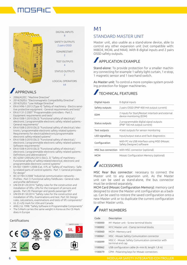
M1STANDARD MASTER UNITMaster unit, also usable as a stand-alone device, able to control any other expansion unit (not compatible with: MI8O4, MO4L and MA4). With 8 digital inputs and 2 pairs OSSD safety outputs.
APPLICATION EXAMPLE
Stand-alone: To provide protection for a smaller machin-ery connecting for example 1 safety light curtain, 1 e-stop, 1 magnetic sensor and 1 two-hand switch.
As Master unit: To control a more complex system provid-ing protection for bigger machineries.
TECHNICAL FEATURES
Digital inputs 8 digital inputs
Safety outputs 2 pairs OSSD (PNP 400 mA output current)
EDM2 inputs for Start/Restart interlock and external device monitoring (EDM)
Status outputs2 programmable digital signal outputs (PNP 100 mA output current)
Test outputs 4 test outputs for sensor monitoring
LED signalling Input/output status and fault diagnostics
ConfigurationWith PC via USB interface using MSD (Mosaic Safety Designer) software
MSC bus connection With MSC connector (optional)
MCM Mosaic Configuration Memory (optional)
ACCESSORIES
MSC Rear Bus connector: necessary to connect the Master unit to any expansion unit. As the Master unit can be used as stand-alone, the bus connector must be ordered separately. MCM Card (Mosaic Configuration Memory): memory card designed to store the Master unit configuration as a back-up. Can be used to restore the saved configuration onto a new Master unit or to duplicate the current configuration to other Master units.
PART NUMBERS
Code Description
1100000 M1 Master unit - Screw terminal blocks
1100002 M1C Master unit - Clamp terminal blocks
1100060 MCM - Memory card
1100061 MSC - Mosaic Safety Comunication connector
1100099MSC-C - Mosaic Safety Comunication connector with terminal end cap
1100062 USB configuration cable (A–mini B, length 1,8 m)
1100079 CPM - Polarizing keys for Mosaic connectors
DIGITAL INPUTS8
SAFETY OUTPUTS2 pairs OSSD
EDM/RESTART2
TEST OUTPUTS4
STATUS OUTPUTS2
LOGICAL OPERATORS64
APPROVALS • 2006/42/EC: “Machine Directive” • 2014/30/EU: “Electromagnetic Compatibility Directive”. • 2014/35/EU: “Low Voltage Directive” • EN 61496-1:2013 (Type 4) “Safety of machinery - Electro sensi-
tive protective equipment - General requirements and tests” • EN 61131-2:2007 “Programmable controllers - Part 2.
Equipment requirements and tests” • EN 61508-1:2010 (SIL3) “Functional safety of electrical /
electronic / programmable electronic safety related systems - General requirements”
• EN 61508-2:2010 (SIL3) “Functional safety of electrical / elec-tronic / programmable electronic safety related systems - Requirements for electrical/electronic/programmable electronic safety-related systems”
• EN 61508-3:2010 (SIL3) “Functional safety of electrical / electronic / programmable electronic safety related systems: Software requirements”
• EN 61508-4:2010 (SIL3) “Functional safety of electrical / electronic / programmable electronic safety related systems - Definitions and abbreviations”
• IEC 62061:2005/A2:2015 (SILCL 3) “Safety of machinery - Functional safety of safety-related electrical, electronic and programmable electronic control systems”
• EN ISO 13849-1:2008 (Cat. 4 PL e) “Safety of machinery - Safe-ty-related parts of control systems - Part 1: General principles for design”
• IEC 61784-3:2008 “Industrial communication networks - Profiles - Part 3: Functional safety fieldbuses - General rules and profile definitions”
• UNI EN 81-20:2014 “Safety rules for the construction and installation of lifts. Lifts for the transport of persons and goods. Part 20: Passenger and goods passenger lift”
• UNI EN 81-50:2014 “Safety rules for the construction and installation of lifts. Examinations and test. Part 50: Design rules, calculations, examinations and tests of lift components”
• UL (C+US) mark for USA and Canada • ANSI / UL 1998: “Safety Software in Programmable Components” • The S-Mark carries the same weight in Korea as the CE-Mark
does in Europe
Certifications
EN 8120/50
SAFETY LEVEL
SIL3 - SILCL 3PL e - Cat. 4
SIL 3
7MODULAR SAFETY INTEGRATED CONTROLLER
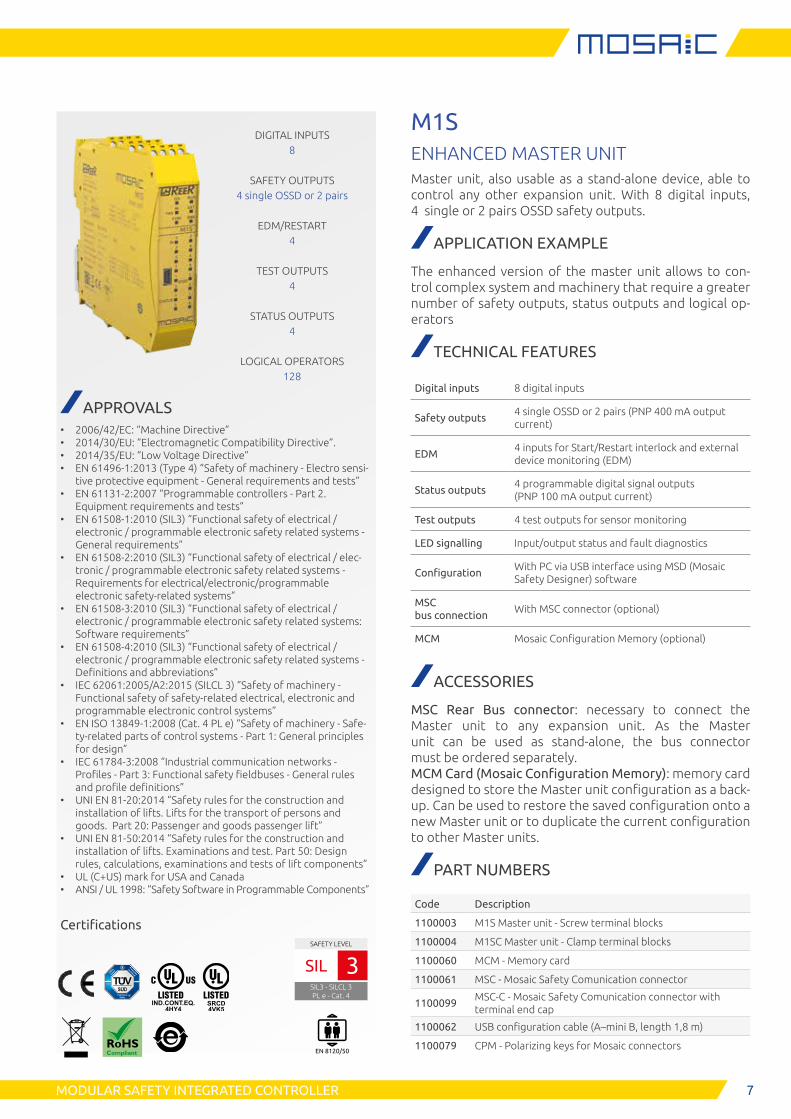
M1SENHANCED MASTER UNITMaster unit, also usable as a stand-alone device, able to control any other expansion unit. With 8 digital inputs, 4 single or 2 pairs OSSD safety outputs.
APPLICATION EXAMPLE
The enhanced version of the master unit allows to con-trol complex system and machinery that require a greater number of safety outputs, status outputs and logical op-erators
TECHNICAL FEATURES
Digital inputs 8 digital inputs
Safety outputs4 single OSSD or 2 pairs (PNP 400 mA output current)
EDM4 inputs for Start/Restart interlock and external device monitoring (EDM)
Status outputs4 programmable digital signal outputs (PNP 100 mA output current)
Test outputs 4 test outputs for sensor monitoring
LED signalling Input/output status and fault diagnostics
ConfigurationWith PC via USB interface using MSD (Mosaic Safety Designer) software
MSC bus connection
With MSC connector (optional)
MCM Mosaic Configuration Memory (optional)
ACCESSORIES
MSC Rear Bus connector: necessary to connect the Master unit to any expansion unit. As the Master unit can be used as stand-alone, the bus connector must be ordered separately. MCM Card (Mosaic Configuration Memory): memory card designed to store the Master unit configuration as a back-up. Can be used to restore the saved configuration onto a new Master unit or to duplicate the current configuration to other Master units.
PART NUMBERS
Code Description
1100003 M1S Master unit - Screw terminal blocks
1100004 M1SC Master unit - Clamp terminal blocks
1100060 MCM - Memory card
1100061 MSC - Mosaic Safety Comunication connector
1100099MSC-C - Mosaic Safety Comunication connector with terminal end cap
1100062 USB configuration cable (A–mini B, length 1,8 m)
1100079 CPM - Polarizing keys for Mosaic connectors
DIGITAL INPUTS8
SAFETY OUTPUTS4 single OSSD or 2 pairs
EDM/RESTART4
TEST OUTPUTS4
STATUS OUTPUTS4
LOGICAL OPERATORS128
APPROVALS • 2006/42/EC: “Machine Directive” • 2014/30/EU: “Electromagnetic Compatibility Directive”. • 2014/35/EU: “Low Voltage Directive” • EN 61496-1:2013 (Type 4) “Safety of machinery - Electro sensi-
tive protective equipment - General requirements and tests” • EN 61131-2:2007 “Programmable controllers - Part 2.
Equipment requirements and tests” • EN 61508-1:2010 (SIL3) “Functional safety of electrical /
electronic / programmable electronic safety related systems - General requirements”
• EN 61508-2:2010 (SIL3) “Functional safety of electrical / elec-tronic / programmable electronic safety related systems - Requirements for electrical/electronic/programmable electronic safety-related systems”
• EN 61508-3:2010 (SIL3) “Functional safety of electrical / electronic / programmable electronic safety related systems: Software requirements”
• EN 61508-4:2010 (SIL3) “Functional safety of electrical / electronic / programmable electronic safety related systems - Definitions and abbreviations”
• IEC 62061:2005/A2:2015 (SILCL 3) “Safety of machinery - Functional safety of safety-related electrical, electronic and programmable electronic control systems”
• EN ISO 13849-1:2008 (Cat. 4 PL e) “Safety of machinery - Safe-ty-related parts of control systems - Part 1: General principles for design”
• IEC 61784-3:2008 “Industrial communication networks - Profiles - Part 3: Functional safety fieldbuses - General rules and profile definitions”
• UNI EN 81-20:2014 “Safety rules for the construction and installation of lifts. Lifts for the transport of persons and goods. Part 20: Passenger and goods passenger lift”
• UNI EN 81-50:2014 “Safety rules for the construction and installation of lifts. Examinations and test. Part 50: Design rules, calculations, examinations and tests of lift components”
• UL (C+US) mark for USA and Canada • ANSI / UL 1998: “Safety Software in Programmable Components”
Certifications
EN 8120/50
SAFETY LEVEL
SIL3 - SILCL 3PL e - Cat. 4
SIL 3
8 MODULAR SAFETY INTEGRATED CONTROLLER
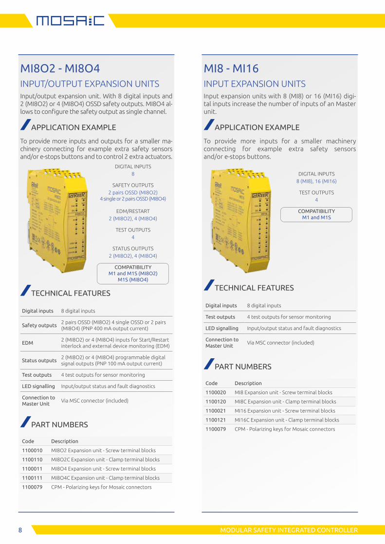
MI8O2 - MI8O4INPUT/OUTPUT EXPANSION UNITSInput/output expansion unit. With 8 digital inputs and 2 (MI8O2) or 4 (MI8O4) OSSD safety outputs. MI8O4 al-lows to configure the safety output as single channel.
APPLICATION EXAMPLE
To provide more inputs and outputs for a smaller ma-chinery connecting for example extra safety sensors and/or e-stops buttons and to control 2 extra actuators.
DIGITAL INPUTS8
SAFETY OUTPUTS2 pairs OSSD (MI8O2)
4 single or 2 pairs OSSD (MI8O4)
EDM/RESTART2 (MI8O2), 4 (MI8O4)
TEST OUTPUTS4
STATUS OUTPUTS2 (MI8O2), 4 (MI8O4)
COMPATIBILITY M1 and M1S (MI8O2)
M1S (MI8O4)
TECHNICAL FEATURES
Digital inputs 8 digital inputs
Safety outputs2 pairs OSSD (MI8O2) 4 single OSSD or 2 pairs (MI8O4) (PNP 400 mA output current)
EDM2 (MI8O2) or 4 (MI8O4) inputs for Start/Restart interlock and external device monitoring (EDM)
Status outputs2 (MI8O2) or 4 (MI8O4) programmable digital signal outputs (PNP 100 mA output current)
Test outputs 4 test outputs for sensor monitoring
LED signalling Input/output status and fault diagnostics
Connection to Master Unit
Via MSC connector (included)
PART NUMBERS
Code Description
1100010 MI8O2 Expansion unit - Screw terminal blocks
1100110 MI8O2C Expansion unit - Clamp terminal blocks
1100011 MI8O4 Expansion unit - Screw terminal blocks
1100111 MI8O4C Expansion unit - Clamp terminal blocks
1100079 CPM - Polarizing keys for Mosaic connectors
MI8 - MI16INPUT EXPANSION UNITSInput expansion units with 8 (MI8) or 16 (MI16) digi-tal inputs increase the number of inputs of an Master unit.
APPLICATION EXAMPLE
To provide more inputs for a smaller machinery connecting for example extra safety sensors and/or e-stops buttons.
DIGITAL INPUTS8 (MI8), 16 (MI16)
TEST OUTPUTS4
COMPATIBILITY M1 and M1S
TECHNICAL FEATURES
Digital inputs 8 digital inputs
Test outputs 4 test outputs for sensor monitoring
LED signalling Input/output status and fault diagnostics
Connection to Master Unit
Via MSC connector (included)
PART NUMBERS
Code Description
1100020 MI8 Expansion unit - Screw terminal blocks
1100120 MI8C Expansion unit - Clamp terminal blocks
1100021 MI16 Expansion unit - Screw terminal blocks
1100121 MI16C Expansion unit - Clamp terminal blocks
1100079 CPM - Polarizing keys for Mosaic connectors
9MODULAR SAFETY INTEGRATED CONTROLLER
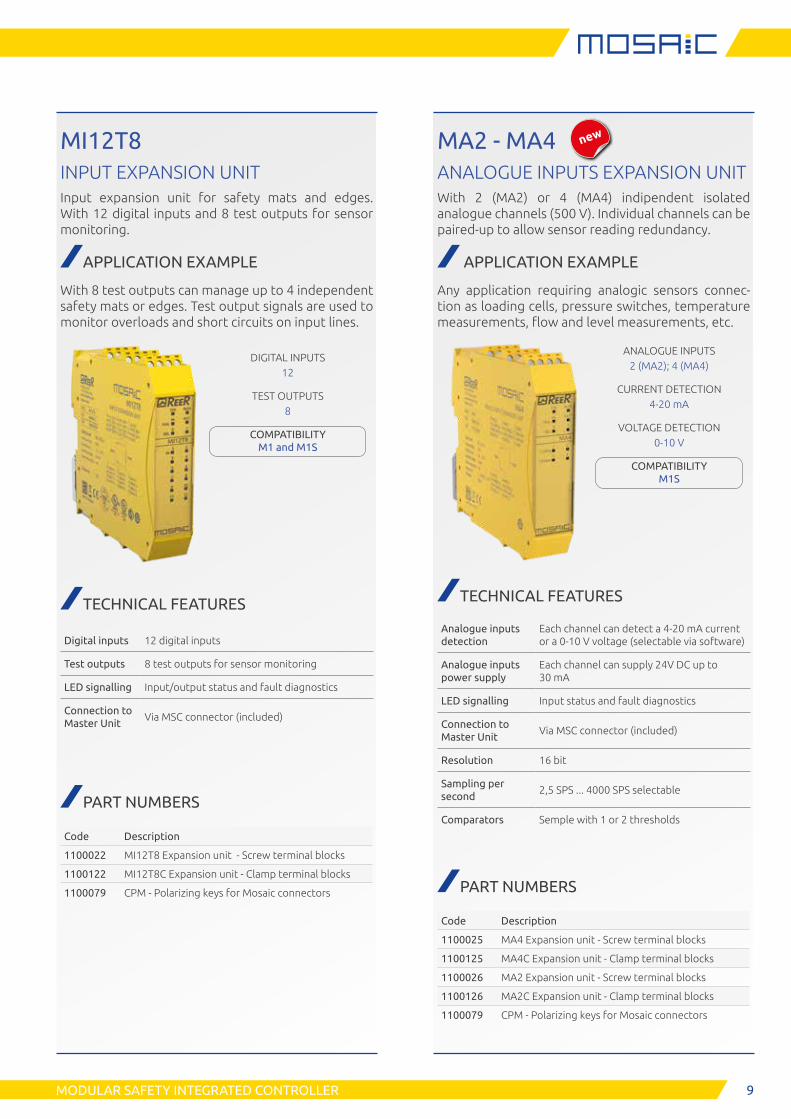
MA2 - MA4ANALOGUE INPUTS EXPANSION UNITWith 2 (MA2) or 4 (MA4) indipendent isolated analogue channels (500 V). Individual channels can be paired-up to allow sensor reading redundancy.
APPLICATION EXAMPLE
Any application requiring analogic sensors connec-tion as loading cells, pressure switches, temperature measurements, flow and level measurements, etc.
ANALOGUE INPUTS2 (MA2); 4 (MA4)
CURRENT DETECTION4-20 mA
VOLTAGE DETECTION0-10 V
COMPATIBILITY M1S
TECHNICAL FEATURES
Analogue inputs detection
Each channel can detect a 4-20 mA current or a 0-10 V voltage (selectable via software)
Analogue inputs power supply
Each channel can supply 24V DC up to 30 mA
LED signalling Input status and fault diagnostics
Connection to Master Unit
Via MSC connector (included)
Resolution 16 bit
Sampling per second
2,5 SPS ... 4000 SPS selectable
Comparators Semple with 1 or 2 thresholds
PART NUMBERS
Code Description
1100025 MA4 Expansion unit - Screw terminal blocks
1100125 MA4C Expansion unit - Clamp terminal blocks
1100026 MA2 Expansion unit - Screw terminal blocks
1100126 MA2C Expansion unit - Clamp terminal blocks
1100079 CPM - Polarizing keys for Mosaic connectors
MI12T8INPUT EXPANSION UNITInput expansion unit for safety mats and edges. With 12 digital inputs and 8 test outputs for sensor monitoring.
APPLICATION EXAMPLE
With 8 test outputs can manage up to 4 independent safety mats or edges. Test output signals are used to monitor overloads and short circuits on input lines.
DIGITAL INPUTS12
TEST OUTPUTS8
COMPATIBILITY M1 and M1S
TECHNICAL FEATURES
Digital inputs 12 digital inputs
Test outputs 8 test outputs for sensor monitoring
LED signalling Input/output status and fault diagnostics
Connection to Master Unit
Via MSC connector (included)
PART NUMBERS
Code Description
1100022 MI12T8 Expansion unit - Screw terminal blocks
1100122 MI12T8C Expansion unit - Clamp terminal blocks
1100079 CPM - Polarizing keys for Mosaic connectors
new
10 MODULAR SAFETY INTEGRATED CONTROLLER
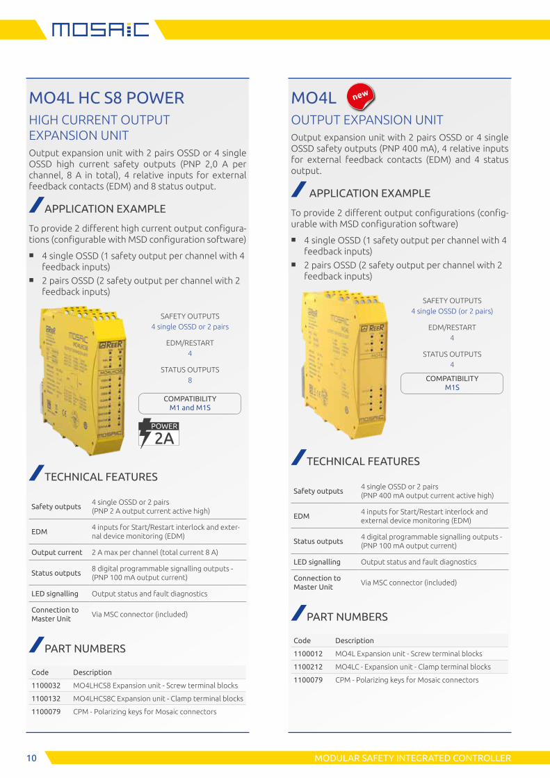
MO4L HC S8 POWERHIGH CURRENT OUTPUT EXPANSION UNITOutput expansion unit with 2 pairs OSSD or 4 single OSSD high current safety outputs (PNP 2,0 A per channel, 8 A in total), 4 relative inputs for external feedback contacts (EDM) and 8 status output.
APPLICATION EXAMPLE
To provide 2 different high current output configura-tions (configurable with MSD configuration software)
■ 4 single OSSD (1 safety output per channel with 4 feedback inputs)
■ 2 pairs OSSD (2 safety output per channel with 2 feedback inputs)
SAFETY OUTPUTS4 single OSSD or 2 pairs
EDM/RESTART4
STATUS OUTPUTS8
COMPATIBILITY M1 and M1S
TECHNICAL FEATURES
Safety outputs4 single OSSD or 2 pairs (PNP 2 A output current active high)
EDM4 inputs for Start/Restart interlock and exter-nal device monitoring (EDM)
Output current 2 A max per channel (total current 8 A)
Status outputs8 digital programmable signalling outputs - (PNP 100 mA output current)
LED signalling Output status and fault diagnostics
Connection to Master Unit
Via MSC connector (included)
PART NUMBERS
Code Description
1100032 MO4LHCS8 Expansion unit - Screw terminal blocks
1100132 MO4LHCS8C Expansion unit - Clamp terminal blocks
1100079 CPM - Polarizing keys for Mosaic connectors
MO4LOUTPUT EXPANSION UNITOutput expansion unit with 2 pairs OSSD or 4 single OSSD safety outputs (PNP 400 mA), 4 relative inputs for external feedback contacts (EDM) and 4 status output.
APPLICATION EXAMPLE
To provide 2 different output configurations (config-urable with MSD configuration software)
■ 4 single OSSD (1 safety output per channel with 4 feedback inputs)
■ 2 pairs OSSD (2 safety output per channel with 2 feedback inputs)
SAFETY OUTPUTS4 single OSSD (or 2 pairs)
EDM/RESTART4
STATUS OUTPUTS4
COMPATIBILITY M1S
TECHNICAL FEATURES
Safety outputs4 single OSSD or 2 pairs (PNP 400 mA output current active high)
EDM4 inputs for Start/Restart interlock and external device monitoring (EDM)
Status outputs4 digital programmable signalling outputs - (PNP 100 mA output current)
LED signalling Output status and fault diagnostics
Connection to Master Unit
Via MSC connector (included)
PART NUMBERS
Code Description
1100012 MO4L Expansion unit - Screw terminal blocks
1100212 MO4LC - Expansion unit - Clamp terminal blocks
1100079 CPM - Polarizing keys for Mosaic connectors
2A2APOWER
new
11MODULAR SAFETY INTEGRATED CONTROLLER
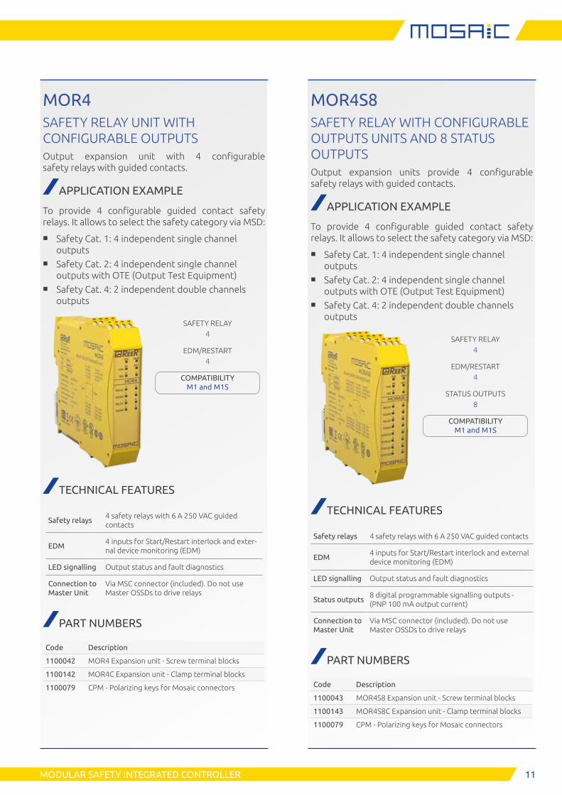
MOR4SAFETY RELAY UNIT WITH CONFIGURABLE OUTPUTSOutput expansion unit with 4 configurable safety relays with guided contacts.
APPLICATION EXAMPLE
To provide 4 configurable guided contact safety relays. It allows to select the safety category via MSD:
■ Safety Cat. 1: 4 independent single channel outputs
■ Safety Cat. 2: 4 independent single channel outputs with OTE (Output Test Equipment)
■ Safety Cat. 4: 2 independent double channels outputs
SAFETY RELAY4
EDM/RESTART4
COMPATIBILITY M1 and M1S
TECHNICAL FEATURES
Safety relays4 safety relays with 6 A 250 VAC guided contacts
EDM4 inputs for Start/Restart interlock and exter-nal device monitoring (EDM)
LED signalling Output status and fault diagnostics
Connection to Master Unit
Via MSC connector (included). Do not use Master OSSDs to drive relays
PART NUMBERS
Code Description
1100042 MOR4 Expansion unit - Screw terminal blocks
1100142 MOR4C Expansion unit - Clamp terminal blocks
1100079 CPM - Polarizing keys for Mosaic connectors
MOR4S8SAFETY RELAY WITH CONFIGURABLE OUTPUTS UNITS AND 8 STATUS OUTPUTSOutput expansion units provide 4 configurable safety relays with guided contacts.
APPLICATION EXAMPLE
To provide 4 configurable guided contact safety relays. It allows to select the safety category via MSD:
■ Safety Cat. 1: 4 independent single channel outputs
■ Safety Cat. 2: 4 independent single channel outputs with OTE (Output Test Equipment)
■ Safety Cat. 4: 2 independent double channels outputs
SAFETY RELAY4
EDM/RESTART4
STATUS OUTPUTS8
COMPATIBILITY M1 and M1S
TECHNICAL FEATURES
Safety relays 4 safety relays with 6 A 250 VAC guided contacts
EDM4 inputs for Start/Restart interlock and external device monitoring (EDM)
LED signalling Output status and fault diagnostics
Status outputs8 digital programmable signalling outputs - (PNP 100 mA output current)
Connection to Master Unit
Via MSC connector (included). Do not use Master OSSDs to drive relays
PART NUMBERS
Code Description
1100043 MOR4S8 Expansion unit - Screw terminal blocks
1100143 MOR4S8C Expansion unit - Clamp terminal blocks
1100079 CPM - Polarizing keys for Mosaic connectors
12 MODULAR SAFETY INTEGRATED CONTROLLER
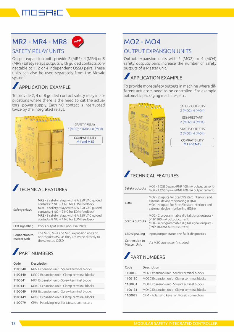
MR2 - MR4 - MR8SAFETY RELAY UNITSOutput expansion units provide 2 (MR2), 4 (MR4) or 8 (MR8) safety relays outputs with guided contacts con-nectable to 1, 2 or 4 independent OSSD pairs. These units can also be used separately from the Mosaic system.
APPLICATION EXAMPLE
To provide 2, 4 or 8 guided contact safety relay in ap-plications where there is the need to cut the actua-tors power supply. Each NO contact is interrupted twice by the integrated relays.
SAFETY RELAY2 (MR2); 4 (MR4); 8 (MR8)
COMPATIBILITY M1 and M1S
TECHNICAL FEATURES
Safety relays
MR2 - 2 safety relays with 6 A 250 VAC guided contacts: 2 NO + 1 NC for EDM feedback MR4 - 4 safety relays with 6 A 250 VAC guided contacts: 4 NO + 2 NC for EDM feedback MR8 - 8 safety relays with 6 A 250 VAC guided contacts: 8 NO + 4 NC for EDM feedback
LED signalling OSSD output status (input in MRx)
Connection to Master Unit
The MR2, MR4 and MR8 expansion units do not require MSC as they are wired directly to the selected OSSD
PART NUMBERS
Code Description
1100040 MR2 Expansion unit - Screw terminal blocks
1100140 MR2C Expansion unit - Clamp terminal blocks
1100041 MR4 Expansion unit - Screw terminal blocks
1100141 MR4C Expansion unit - Clamp terminal blocks
1100049 MR8 Expansion unit - Screw terminal blocks
1100149 MR8C Expansion unit - Clamp terminal blocks
1100079 CPM - Polarizing keys for Mosaic connectors
MO2 - MO4OUTPUT EXPANSION UNITSOutput expansion units with 2 (MO2) or 4 (MO4) safety outputs pairs increase the number of safety outputs of a Master unit.
APPLICATION EXAMPLE
To provide more safety outputs in machine where dif-ferent actuators need to be controlled. For example automatic packaging machines, etc.
SAFETY OUTPUTS2 (MO2), 4 (MO4)
EDM/RESTART2 (MO2), 4 (MO4)
STATUS OUTPUTS2 (MO2), 4 (MO4)
COMPATIBILITY M1 and M1S
TECHNICAL FEATURES
Safety outputsMO2 - 2 OSSD pairs (PNP 400 mA output current) MO4 - 4 OSSD pairs (PNP 400 mA output current)
EDM
MO2 - 2 inputs for Start/Restart interlock and external device monitoring (EDM) MO4 - 4 inputs for Start/Restart interlock and external device monitoring (EDM)
Status outputs
MO2 - 2 programmable digital signal outputs - (PNP 100 mA output current) MO4 - 4 programmable digital signal outputs - (PNP 100 mA output current)
LED signalling Input/output status and fault diagnostics
Connection to Master Unit
Via MSC connector (included)
PART NUMBERS
Code Description
1100030 MO2 Expansion unit - Screw terminal blocks
1100130 MO2C Expansion unit - Clamp terminal blocks
1100031 MO4 Expansion unit - Screw terminal blocks
1100131 MO4C Expansion unit - Clamp terminal blocks
1100079 CPM - Polarizing keys for Mosaic connectors
new
13MODULAR SAFETY INTEGRATED CONTROLLER
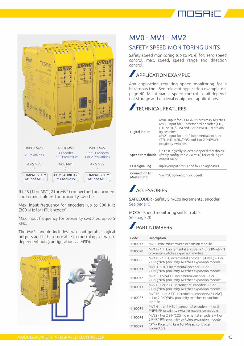
INPUT MV0 INPUT MV1 INPUT MV2
2 Proximities1 Encoder
1 or 2 Proximities1 or 2 Encoders
1 or 2 Proximities
AXIS MV0 AXIS MV1 AXIS MV22 2 2
COMPATIBILITY M1 and M1S
COMPATIBILITY M1 and M1S
COMPATIBILITY M1 and M1S
RJ-45 (1 for MV1, 2 for MV2) connectors for encoders and terminal blocks for proximity switches.
Max. input frequency for encoders: up to 500 KHz (300 KHz for HTL encoder).
Max. input frequency for proximity switches: up to 5 KHz.
The MV2 module includes two configurable logical outputs and is therefore able to control up to two in-dependent axis (configuration via MSD).
MV0 - MV1 - MV2SAFETY SPEED MONITORING UNITSSafety speed monitoring (up to PL e) for: zero speed control, max. speed, speed range and direction control.
APPLICATION EXAMPLE
Any application requiring speed monitoring for a hazardous tool. See relevant application example on-page 40. Maintenance speed control in rail depend-ent storage and retrieval equipment applications.
TECHNICAL FEATURES
Digital inputs
MV0 - Input for 2 PNP/NPN proximity switches MV1 - Input for 1 incremental encoder (TTL, HTL or SIN/COS) and 1 or 2 PNP/NPN proxim-ity switches MV2 - Input for 1 or 2 incremental encoder (TTL, HTL o SIN/COS) and 1 or 2 PNP/NPN proximity switches
Speed thresholdsUp to 8 logically selectable speed thresholds (freely configurable via MSD) for each logical output (axis)
LED signalling Input/output status and fault diagnostics
Connection to Master Unit
Via MSC connector (included)
ACCESSORIES
SAFECODER - Safety Sin/Cos incremental encoder. See page15
MCCV - Speed monitoring sniffer cable. See page 20
PART NUMBERS
Code Description
1100077 MV0 - Proximities switch expansion module
1100070MV1T - 1 TTL incremental encoder + 1 or 2 PNP/NPN proximity switches expansion module
1100086MV1TB - 1 TTL incremental encoder (24 VDC) + 1 or 2 PNP/NPN proximity switches expansion module
1100071MV1H - 1 HTL incremental encoder + 1 or 2 PNP/NPN proximity switches expansion module
1100072MV1S - 1 SIN/COS incremental encoder + 1 or 2 PNP/NPN proximity switches expansion module
1100073MV2T - 1 or 2 TTL incremental encoders + 1 or 2 PNP/NPN proximity switches expansion module
1100087MV2TB - 1 or 2 TTL incremental encoders (24 VDC) + 1 or 2 PNP/NPN proximity switches expansion module
1100074MV2H - 1 or 2 HTL incremental encoders + 1 or 2 PNP/NPN proximity switches expansion module
1100076MV2S - 1 or 2 SIN/COS incremental encoders + 1 or 2 PNP/NPN proximity switches expansion module
1100079CPM - Polarizing keys for Mosaic controller connectors
14 MODULAR SAFETY INTEGRATED CONTROLLER
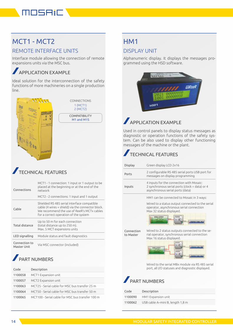
MCT1 - MCT2REMOTE INTERFACE UNITSInterface module allowing the connection of remote expansions units via the MSC bus.
APPLICATION EXAMPLE
Ideal solution for the interconnection of the safety functions of more machineries on a single production line.
CONNECTIONS1 (MCT1) 2 (MCT2)
COMPATIBILITY M1 and M1S
TECHNICAL FEATURES
Connections
MCT1 - 1 connection: 1 input or 1 output to be placed at the beginning or at the end of the network
MCT2 - 2 connections: 1 input and 1 output
Cable
Shielded RS 485 serial interface compatible cable (4 wires + shield) via the connector block. We recommend the use of ReeR’s MCTx cables for a correct operation of the system
Total distanceUp to 50 m for each connection (total distance up to 250 m). Max. 5 MCT expansions units
LED signalling Module status and fault diagnostics
Connection to Master Unit
Via MSC connector (included)
PART NUMBERS
Code Description
1100058 MCT1 Expansion unit
1100057 MCT2 Expansion unit
1100063 MCT25 - Serial cable for MSC bus transfer 25 m
1100064 MCT50 - Serial cable for MSC bus transfer 50 m
1100065 MCT100 - Serial cable for MSC bus transfer 100 m
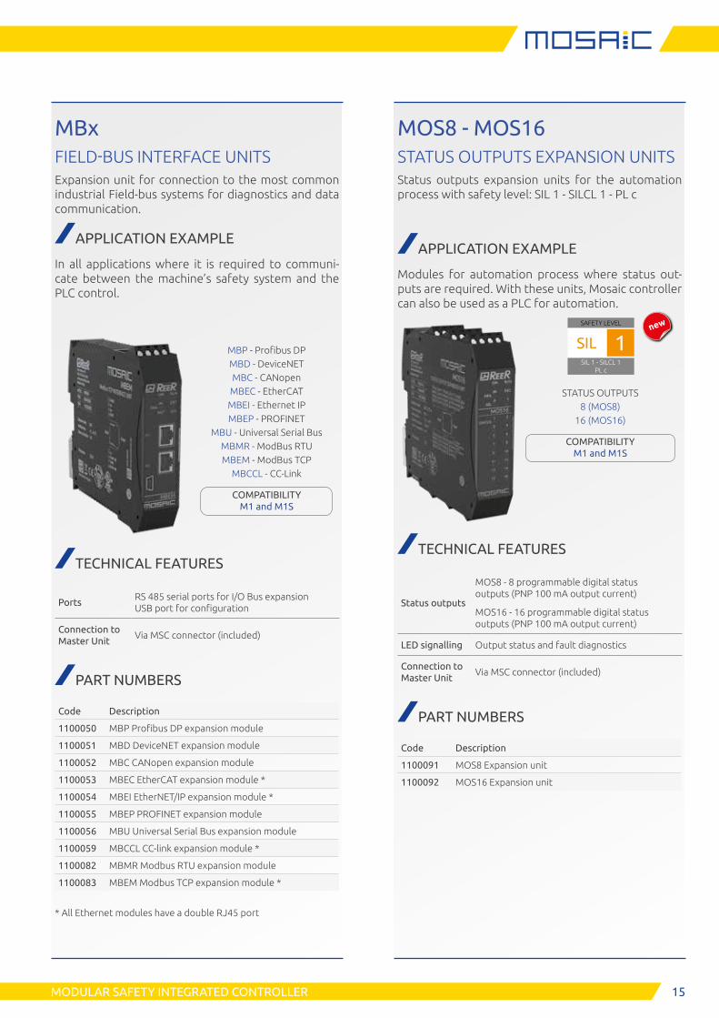
HM1DISPLAY UNITAlphanumeric display. It displays the messages pro-grammed using the HSD software.
APPLICATION EXAMPLE
Used in control panels to display status messages as diagnostic or operation functions of the safety sys-tem. Can be also used to display other functioning messages of the machine or the plant.
TECHNICAL FEATURES
Display Green display LCD 2x16
Ports2 configurable RS 485 serial ports USB port for messages on display programming
Inputs4 inputs for the connection with Mosaic: 2 synchronous serial ports (clock + data) or 4 asynchronous serial ports (data)
Connection to Master
HM1 can be connected to Mosaic in 3 ways:
Wired to a status output connected to the serial operator, asynchronous serial connection Max 32 status displayed.
Wired to 2 status outputs connected to the se-rial operator, synchronous serial connection Max 16 status displayed.
Wired to the serial MBx module via RS 485 serial port, all I/O statuses and diagnostic displayed.
PART NUMBERS
Code Description
1100090 HM1 Expansion unit
1100062 USB cable A–mini B, length 1,8 m
15MODULAR SAFETY INTEGRATED CONTROLLER
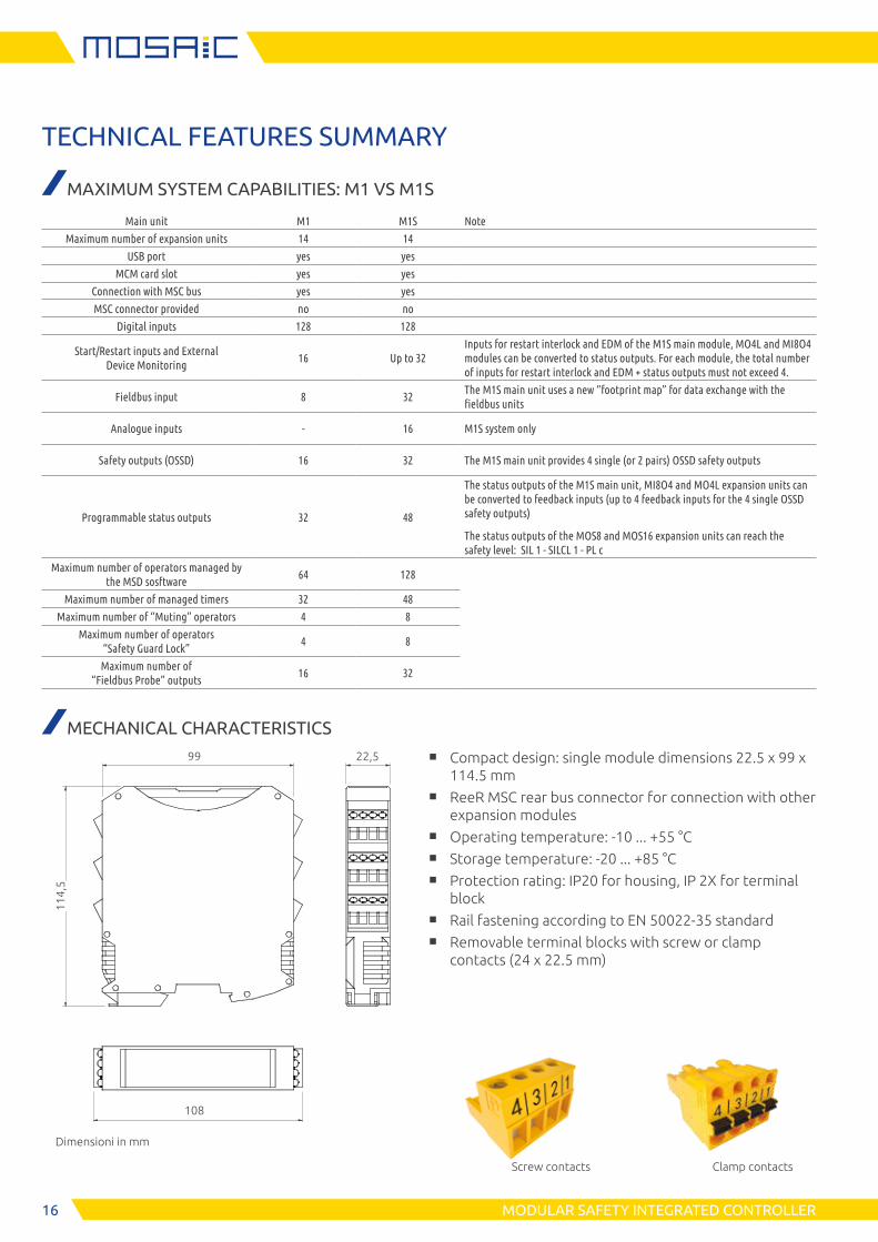
MBxFIELD-BUS INTERFACE UNITSExpansion unit for connection to the most common industrial Field-bus systems for diagnostics and data communication.
APPLICATION EXAMPLE
In all applications where it is required to communi-cate between the machine’s safety system and the PLC control.
MBP - Profibus DPMBD - DeviceNETMBC - CANopen
MBEC - EtherCATMBEI - Ethernet IPMBEP - PROFINET
MBU - Universal Serial BusMBMR - ModBus RTUMBEM - ModBus TCP
MBCCL - CC-Link
COMPATIBILITY M1 and M1S
TECHNICAL FEATURES
PortsRS 485 serial ports for I/O Bus expansion USB port for configuration
Connection to Master Unit
Via MSC connector (included)
PART NUMBERS
Code Description
1100050 MBP Profibus DP expansion module
1100051 MBD DeviceNET expansion module
1100052 MBC CANopen expansion module
1100053 MBEC EtherCAT expansion module *
1100054 MBEI EtherNET/IP expansion module *
1100055 MBEP PROFINET expansion module
1100056 MBU Universal Serial Bus expansion module
1100059 MBCCL CC-link expansion module *
1100082 MBMR Modbus RTU expansion module
1100083 MBEM Modbus TCP expansion module *
* All Ethernet modules have a double RJ45 port
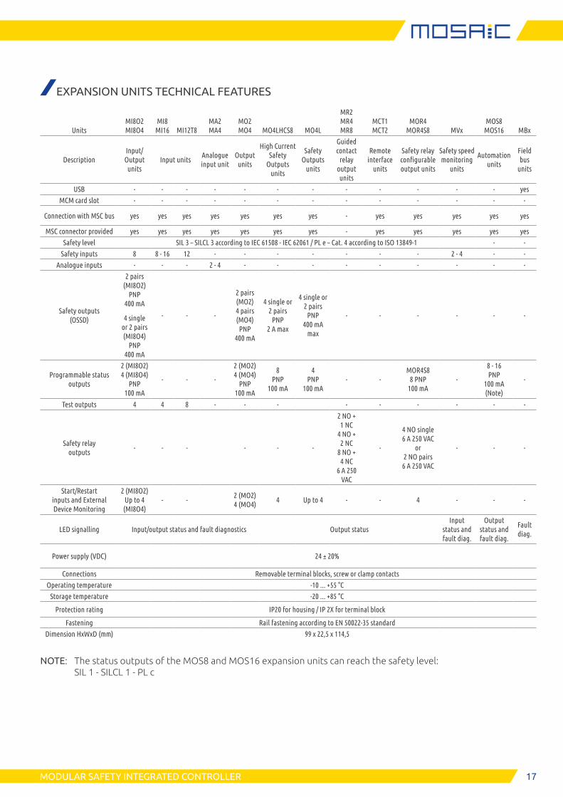
MOS8 - MOS16STATUS OUTPUTS EXPANSION UNITSStatus outputs expansion units for the automation process with safety level: SIL 1 - SILCL 1 - PL c
APPLICATION EXAMPLE
Modules for automation process where status out-puts are required. With these units, Mosaic controller can also be used as a PLC for automation.
SAFETY LEVEL
SIL 1 - SILCL 1PL c
SIL 1
STATUS OUTPUTS8 (MOS8)
16 (MOS16)
COMPATIBILITY M1 and M1S
TECHNICAL FEATURES
Status outputs
MOS8 - 8 programmable digital status outputs (PNP 100 mA output current)
MOS16 - 16 programmable digital status outputs (PNP 100 mA output current)
LED signalling Output status and fault diagnostics
Connection to Master Unit
Via MSC connector (included)
PART NUMBERS
Code Description
1100091 MOS8 Expansion unit
1100092 MOS16 Expansion unit
new
16 MODULAR SAFETY INTEGRATED CONTROLLER
TECHNICAL FEATURES SUMMARY
MAXIMUM SYSTEM CAPABILITIES: M1 VS M1S
Main unit M1 M1S Note
Maximum number of expansion units 14 14
USB port yes yes
MCM card slot yes yes
Connection with MSC bus yes yes
MSC connector provided no no
Digital inputs 128 128
Start/Restart inputs and External Device Monitoring
16 Up to 32Inputs for restart interlock and EDM of the M1S main module, MO4L and MI8O4 modules can be converted to status outputs. For each module, the total number of inputs for restart interlock and EDM + status outputs must not exceed 4.
Fieldbus input 8 32The M1S main unit uses a new “footprint map” for data exchange with the fieldbus units
Analogue inputs - 16 M1S system only
Safety outputs (OSSD) 16 32 The M1S main unit provides 4 single (or 2 pairs) OSSD safety outputs
Programmable status outputs 32 48
The status outputs of the M1S main unit, MI8O4 and MO4L expansion units can be converted to feedback inputs (up to 4 feedback inputs for the 4 single OSSD safety outputs)
The status outputs of the MOS8 and MOS16 expansion units can reach the safety level: SIL 1 - SILCL 1 - PL c
Maximum number of operators managed by the MSD sosftware
64 128
Maximum number of managed timers 32 48
Maximum number of “Muting” operators 4 8
Maximum number of operators “Safety Guard Lock”
4 8
Maximum number of “Fieldbus Probe” outputs
16 32
MECHANICAL CHARACTERISTICS
99 22,5
114,
5
108
Dimensioni in mm
Screw contacts Clamp contacts
■ Compact design: single module dimensions 22.5 x 99 x 114.5 mm
■ ReeR MSC rear bus connector for connection with other expansion modules
■ Operating temperature: -10 ... +55 °C ■ Storage temperature: -20 ... +85 °C ■ Protection rating: IP20 for housing, IP 2X for terminal
block ■ Rail fastening according to EN 50022-35 standard ■ Removable terminal blocks with screw or clamp
contacts (24 x 22.5 mm)
17MODULAR SAFETY INTEGRATED CONTROLLER
EXPANSION UNITS TECHNICAL FEATURES
UnitsMI8O2 MI8O4
MI8 MI16 MI12T8
MA2 MA4
MO2 MO4 MO4LHCS8 MO4L
MR2 MR4 MR8
MCT1 MCT2
MOR4 MOR4S8 MVx
MOS8 MOS16 MBx
DescriptionInput/ Output
unitsInput units
Analogue input unit
Output units
High Current Safety
Outputs units
Safety Outputs
units
Guided contact
relay output units
Remote interface
units
Safety relay configurable output units
Safety speed monitoring
units
Automation units
Field bus
units
USB - - - - - - - - - - - - yes
MCM card slot - - - - - - - - - - - - -
Connection with MSC bus yes yes yes yes yes yes yes - yes yes yes yes yes
MSC connector provided yes yes yes yes yes yes yes - yes yes yes yes yes
Safety level SIL 3 – SILCL 3 according to IEC 61508 - IEC 62061 / PL e – Cat. 4 according to ISO 13849-1 - -
Safety inputs 8 8 - 16 12 - - - - - - - 2 - 4 - -
Analogue inputs - - - 2 - 4 - - - - - - - - -
Safety outputs (OSSD)
2 pairs (MI8O2)
PNP 400 mA
4 single or 2 pairs (MI8O4)
PNP 400 mA
- - -
2 pairs (MO2) 4 pairs (MO4) PNP
400 mA
4 single or 2 pairs
PNP 2 A max
4 single or 2 pairs
PNP 400 mA
max
- - - - - -
Programmable status outputs
2 (MI8O2) 4 (MI8O4)
PNP 100 mA
- - -
2 (MO2) 4 (MO4)
PNP 100 mA
8 PNP
100 mA
4 PNP
100 mA- -
MOR4S8 8 PNP
100 mA-
8 - 16 PNP
100 mA (Note)
-
Test outputs 4 4 8 - - - - - - - - -
Safety relay outputs
- - - - - -
2 NO + 1 NC
4 NO + 2 NC
8 NO + 4 NC
6 A 250 VAC
-
4 NO single 6 A 250 VAC
or 2 NO pairs
6 A 250 VAC
- - -
Start/Restart inputs and External Device Monitoring
2 (MI8O2) Up to 4
(MI8O4)- -
2 (MO2) 4 (MO4)
4 Up to 4 - - 4 - - -
LED signalling Input/output status and fault diagnostics Output statusInput
status and fault diag.
Output status and fault diag.
Fault diag.
Power supply (VDC) 24 ± 20%
Connections Removable terminal blocks, screw or clamp contacts
Operating temperature -10 ... +55 °C
Storage temperature -20 ... +85 °C
Protection rating IP20 for housing / IP 2X for terminal block
Fastening Rail fastening according to EN 50022-35 standard
Dimension HxWxD (mm) 99 x 22,5 x 114,5
NOTE: The status outputs of the MOS8 and MOS16 expansion units can reach the safety level: SIL 1 - SILCL 1 - PL c
18
Shaft version
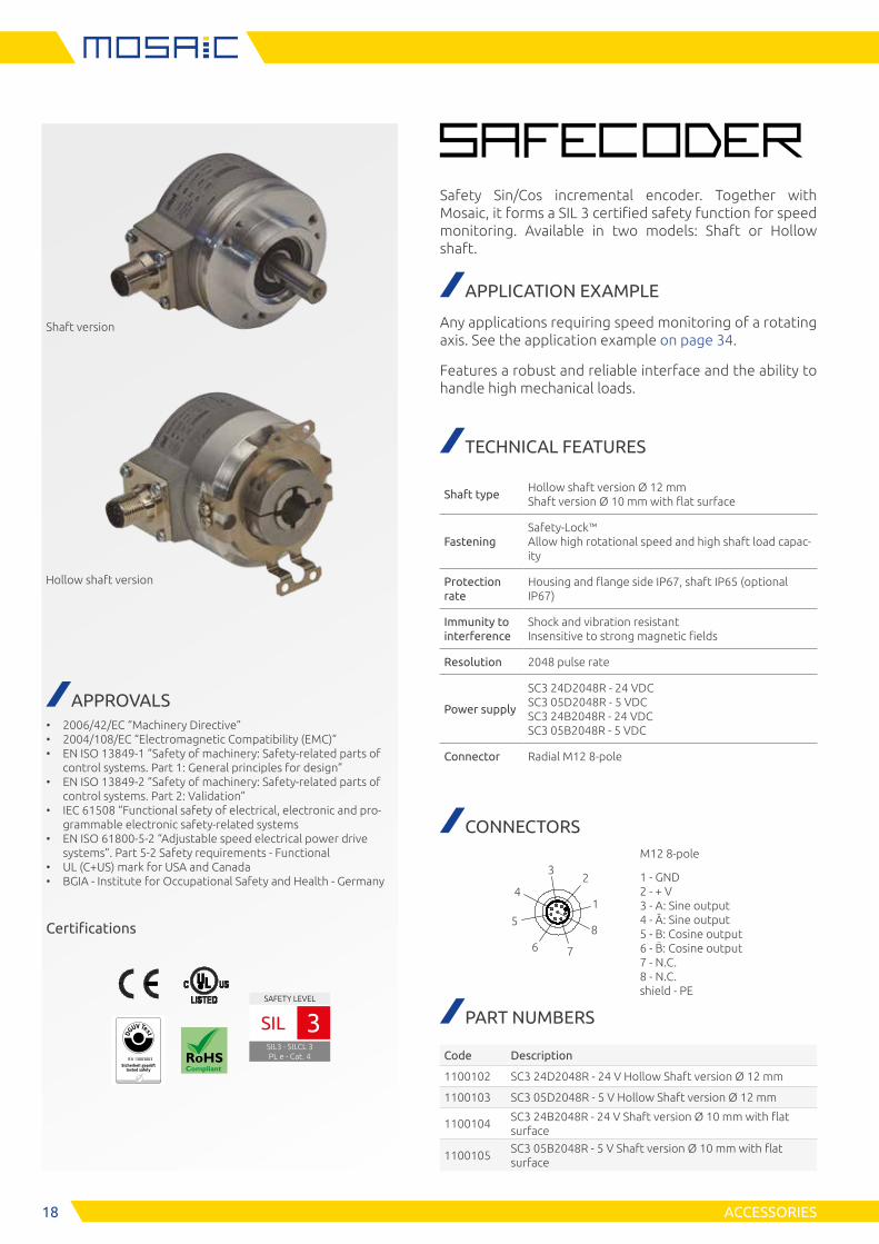
Safety Sin/Cos incremental encoder. Together with Mosaic, it forms a SIL 3 certified safety function for speed monitoring. Available in two models: Shaft or Hollow shaft.
Hollow shaft version
APPROVALS • 2006/42/EC “Machinery Directive” • 2004/108/EC “Electromagnetic Compatibility (EMC)” • EN ISO 13849-1 “Safety of machinery: Safety-related parts of
control systems. Part 1: General principles for design” • EN ISO 13849-2 “Safety of machinery: Safety-related parts of
control systems. Part 2: Validation” • IEC 61508 “Functional safety of electrical, electronic and pro-
grammable electronic safety-related systems • EN ISO 61800-5-2 “Adjustable speed electrical power drive
systems”. Part 5-2 Safety requirements - Functional • UL (C+US) mark for USA and Canada • BGIA - Institute for Occupational Safety and Health - Germany
Certifications
APPLICATION EXAMPLE
Any applications requiring speed monitoring of a rotating axis. See the application example on page 34.
Features a robust and reliable interface and the ability to handle high mechanical loads.
TECHNICAL FEATURES
Shaft typeHollow shaft version Ø 12 mm Shaft version Ø 10 mm with flat surface
FasteningSafety-Lock™ Allow high rotational speed and high shaft load capac-ity
Protection rate
Housing and flange side IP67, shaft IP65 (optional IP67)
Immunity to interference
Shock and vibration resistant Insensitive to strong magnetic fields
Resolution 2048 pulse rate
Power supply
SC3 24D2048R - 24 VDC SC3 05D2048R - 5 VDC SC3 24B2048R - 24 VDC SC3 05B2048R - 5 VDC
Connector Radial M12 8-pole
CONNECTORS
42
3
1
5
6 7
8
M12 8-pole
1 - GND 2 - + V 3 - A: Sine output 4 - Ā: Sine output 5 - B: Cosine output 6 - B: Cosine output 7 - N.C. 8 - N.C. shield - PE
PART NUMBERS
Code Description
1100102 SC3 24D2048R - 24 V Hollow Shaft version Ø 12 mm
1100103 SC3 05D2048R - 5 V Hollow Shaft version Ø 12 mm
1100104SC3 24B2048R - 24 V Shaft version Ø 10 mm with flat surface
1100105SC3 05B2048R - 5 V Shaft version Ø 10 mm with flat surface
ACCESSORIES
E S P E
IFA 13003003
SAFETY LEVEL
SIL3 - SILCL 3PL e - Cat. 4
SIL 3
1919ACCESSORIES
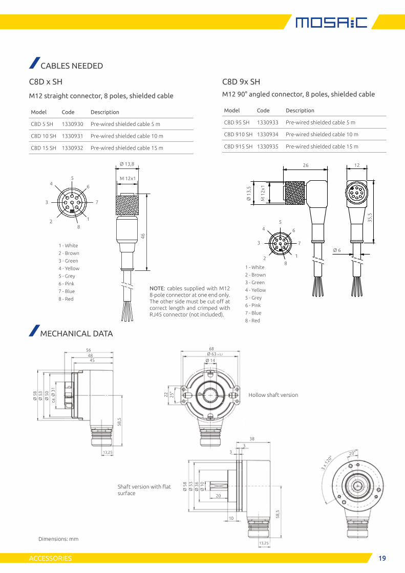
CABLES NEEDED
NOTE: cables supplied with M12 8-pole connector at one end only. The other side must be cut off at correct length and crimped with RJ45 connector (not included).
Shaft version with flat surface
C8D x SH
M12 straight connector, 8 poles, shielded cable
Model Code Description
C8D 5 SH 1330930 Pre-wired shielded cable 5 m
C8D 10 SH 1330931 Pre-wired shielded cable 10 m
C8D 15 SH 1330932 Pre-wired shielded cable 15 m
Ø 13,8
M 12x1
46
1 - White
2 - Brown
3 - Green
4 - Yellow
5 - Grey
6 - Pink
7 - Blue
8 - Red
2
3
54
1
6
8
7
Ø 1
3,5
M 1
2x1
35,5
1 - White
2 - Brown
3 - Green
4 - Yellow
5 - Grey
6 - Pink
7 - Blue
8 - Red
2
3
54
1
6
8
7Ø 6
26 12
C8D 9x SH
M12 90° angled connector, 8 poles, shielded cable
Model Code Description
C8D 95 SH 1330933 Pre-wired shielded cable 5 m
C8D 910 SH 1330934 Pre-wired shielded cable 10 m
C8D 915 SH 1330935 Pre-wired shielded cable 15 m
MECHANICAL DATA
Hollow shaft version
Ø 5
8Ø
53
Ø 3
6Ø
10
20
10
13,25
38
33
58,5
3 x
120°
20°
Ø 5
8Ø
53
Ø 5
0
ca. Ø
31
564845
13,25
58,5
68Ø 63 ± 0,1
Ø 14
22 25°
Dimensions: mm
20 ACCESSORIES
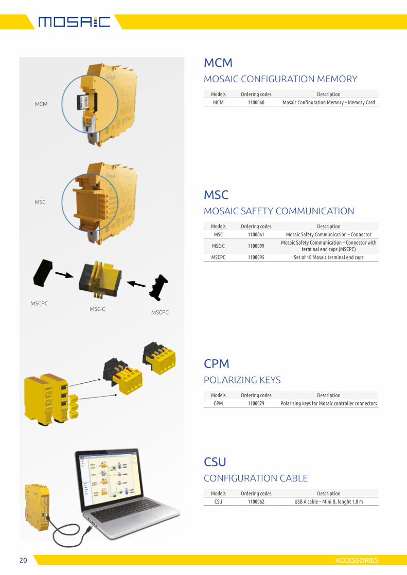
MCMMOSAIC CONFIGURATION MEMORY
Models Ordering codes Description
MCM 1100060 Mosaic Configuration Memory – Memory Card
MSCMOSAIC SAFETY COMMUNICATION
Models Ordering codes Description
MSC 1100061 Mosaic Safety Communication – Connector
MSC-C 1100099Mosaic Safety Communication – Connector with
terminal end caps (MSCPC)
MSCPC 1100095 Set of 10 Mosaic terminal end caps
CPMPOLARIZING KEYS
Models Ordering codes Description
CPM 1100079 Polarizing keys for Mosaic controller connectors
CSUCONFIGURATION CABLE
Models Ordering codes Description
CSU 1100062 USB A cable – Mini B, lenght 1,8 m
MSCPC
MSCPCMSC-C
MSC
MCM
2121ACCESSORIES
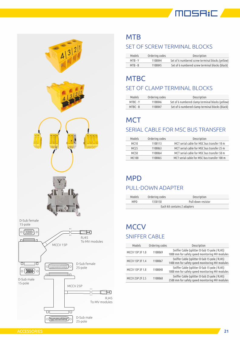
MTBSET OF SCREW TERMINAL BLOCKS
Models Ordering codes Description
MTB - Y 1100044 Set of 6 numbered screw terminal blocks (yellow)
MTB - B 1100045 Set of 6 numbered screw terminal blocks (black)
MTBCSET OF CLAMP TERMINAL BLOCKS
Models Ordering codes Description
MTBC - Y 1100046 Set of 6 numbered clamp terminal blocks (yellow)
MTBC - B 1100047 Set of 6 numbered clamp terminal blocks (black)
MCTSERIAL CABLE FOR MSC BUS TRANSFER
Models Ordering codes Description
MC10 1100113 MCT serial cable for MSC bus transfer 10 m
MC25 1100063 MCT serial cable for MSC bus transfer 25 m
MC50 1100064 MCT serial cable for MSC bus transfer 50 m
MC100 1100065 MCT serial cable for MSC bus transfer 100 m
MPDPULL-DOWN ADAPTER
Models Ordering codes Description
MPD 1350150 Pull-down resistor
Each kit contains 2 adapters
MCCVSNIFFER CABLE
Models Ordering codes Description
MCCV 15P 3F 1.0 1100069Sniffer Cable (splitter D-Sub 15-pole / RJ45)
1000 mm for safety speed monitoring MV modules
MCCV 15P 3F 1.4 1100067Sniffer Cable (splitter D-Sub 15-pole / RJ45)
1400 mm for safety speed monitoring MV modules
MCCV 15P 3F 1.8 1100048Sniffer Cable (splitter D-Sub 15-pole / RJ45)
1800 mm for safety speed monitoring MV modules
MCCV 25P 2F 2.5 1100068Sniffer Cable (splitter D-Sub 25-pole / RJ45)
2500 mm for safety speed monitoring MV modules
D-Sub female 25-pole
D-Sub male 25-pole
RJ45 To MV modules
D-Sub female 15-pole
D-Sub male 15-pole
RJ45 To MV modules
MCCV 15P
MCCV 25P
22 MOSAIC SAFETY DESIGNER
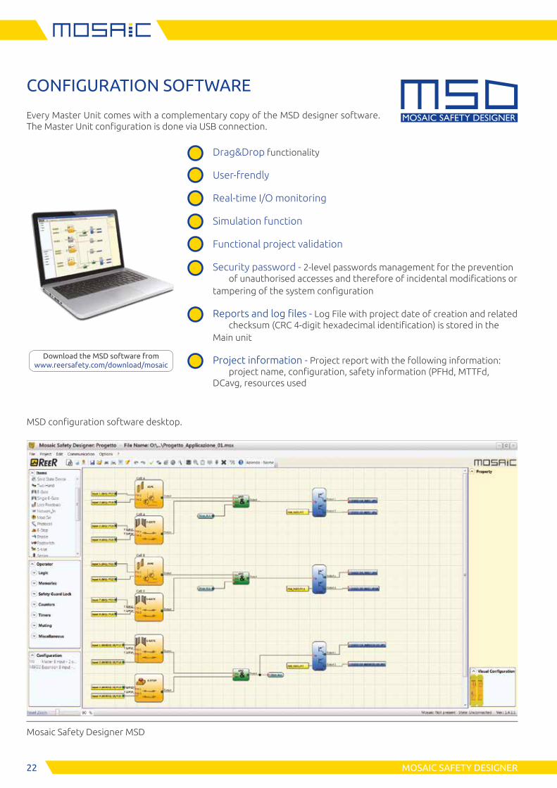
CONFIGURATION SOFTWARE
Every Master Unit comes with a complementary copy of the MSD designer software. The Master Unit configuration is done via USB connection.
MSD configuration software desktop.
Mosaic Safety Designer MSD
Drag&Drop functionality
User-frendly
Real-time I/O monitoring
Simulation function
Functional project validation
Security password - 2-level passwords management for the prevention of unauthorised accesses and therefore of incidental modifications or
tampering of the system configuration
Reports and log files - Log File with project date of creation and related checksum (CRC 4-digit hexadecimal identification) is stored in the
Main unit
Project information - Project report with the following information: project name, configuration, safety information (PFHd, MTTFd,
DCavg, resources used
Download the MSD software from www.reersafety.com/download/mosaic
23MOSAIC SAFETY DESIGNER
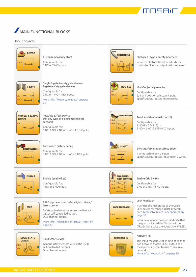
MAIN FUNCTIONAL BLOCKS
Input objects
E-stop (emergency stop)
Configurable for: 1 NC or 2 NC inputs.
Photocell (Type 2 safety photocell)
Input for photocells that need external controller. Specific output test is required.
Single E-gate (safety gate device) E-gate (safety gate device)
Configurable for: 2 NC or 1 NC + 1NO inputs.
More info: “Property window” on page 29.
Mod-Sel (safety selector)
Configurable for: 2, 3 or 4 position selectors inputs. Specific output test is not required.
Testable Safety Device (for any type of electromechanical sensors)
Configurable for: 1 NC, 1 NO, 2 NC or 1 NC + 1 NO inputs.
Two-Hand (bi-manual control)
Configurable for: 2 NO (EN 574 III A) or 2 NO + 2 NC (EN 574 III C) inputs.
Footswitch (safety pedal)
Configurable for: 1 NC, 1 NO, 2 NC or 1 NO + 1 NC inputs.
S-Mat (safety mat or safety edge)
4 wires technology. 2 inputs Specific output test is required on 2 wires.
Enable (enable key)
Configurable for: 1 NO or 2 NO inputs.
Enable Grip Switch
Configurable for 2 NC or 2 NO + 1 NC inputs.
ESPE (optoeletronic safety light curtain / laser scanner)
Safety optoelectronics sensors with static OSSD, self-controlled output Dual channel inputs.
More info: “Automatic or Manual Reset” on page 29.
Lock Feedback
It verifies the lock status of the Guard Lock device for mobile guard or safety gate. More info: Guard Lock operator on page 32.
In the case where the inputs indicate that the guard is locked the Output will be 1 (TRUE). Otherwise the output is 0 (FALSE).
Solid State Device
Generic safety sensors with static OSSD self-controlled outputs Dual channel inputs.
Network_In
This input must be used in case of connec-tion between Mosaic OSSD output and the input of another Mosaic to realize a network. More info: “Network_In” on page 29.
24 MOSAIC SAFETY DESIGNER
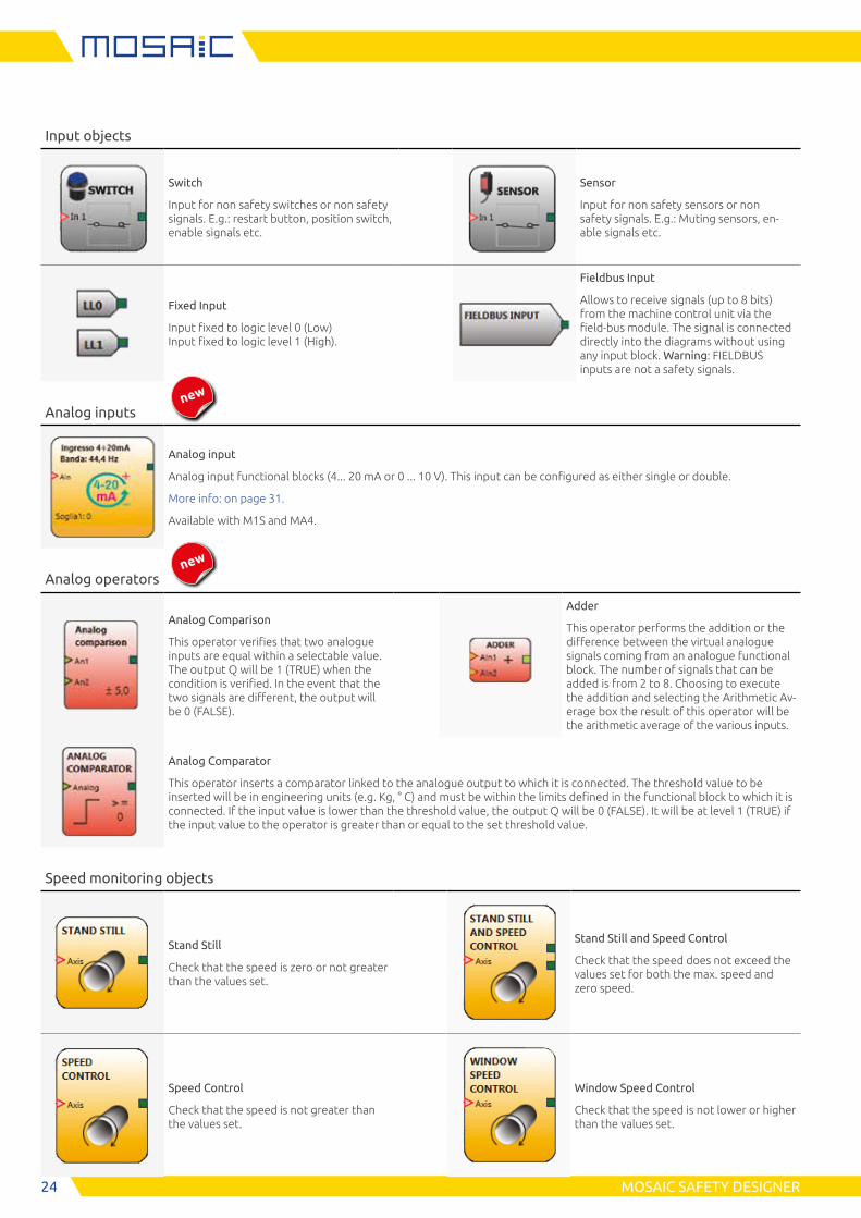
Input objects
Switch
Input for non safety switches or non safety signals. E.g.: restart button, position switch, enable signals etc.
Sensor
Input for non safety sensors or non safety signals. E.g.: Muting sensors, en-able signals etc.
Fixed Input
Input fixed to logic level 0 (Low) Input fixed to logic level 1 (High).
Fieldbus Input
Allows to receive signals (up to 8 bits) from the machine control unit via the field-bus module. The signal is connected directly into the diagrams without using any input block. Warning: FIELDBUS inputs are not a safety signals.
Analog inputs
Analog input
Analog input functional blocks (4... 20 mA or 0 ... 10 V). This input can be configured as either single or double.
More info: on page 31.
Available with M1S and MA4.
Analog operators
Analog Comparison
This operator verifies that two analogue inputs are equal within a selectable value. The output Q will be 1 (TRUE) when the condition is verified. In the event that the two signals are different, the output will be 0 (FALSE).
Adder
This operator performs the addition or the difference between the virtual analogue signals coming from an analogue functional block. The number of signals that can be added is from 2 to 8. Choosing to execute the addition and selecting the Arithmetic Av-erage box the result of this operator will be the arithmetic average of the various inputs.
Analog Comparator
This operator inserts a comparator linked to the analogue output to which it is connected. The threshold value to be inserted will be in engineering units (e.g. Kg, ° C) and must be within the limits defined in the functional block to which it is connected. If the input value is lower than the threshold value, the output Q will be 0 (FALSE). It will be at level 1 (TRUE) if the input value to the operator is greater than or equal to the set threshold value.
Speed monitoring objects
Stand Still
Check that the speed is zero or not greater than the values set.
Stand Still and Speed Control
Check that the speed does not exceed the values set for both the max. speed and zero speed.
Speed Control
Check that the speed is not greater than the values set.
Window Speed Control
Check that the speed is not lower or higher than the values set.
new
new
25MOSAIC SAFETY DESIGNER
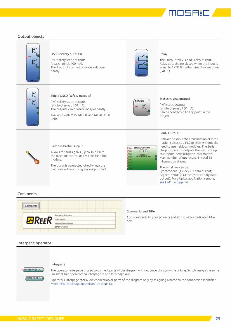
Output objects
OSSD (safety outputs)
PNP safety static outputs (dual channel, 400 mA). The 2 outputs cannot operate indepen-dently.
Relay
The Output relay is a NO relay output. Relay outputs are closed when the input is equal to 1 (TRUE), otherwise they are open (FALSE).
Single OSSD (safety outputs)
PNP safety static outputs (single channel, 400 mA). The outputs can operate independently.
Available with M1S, MI8O4 and MO4LHCS8 units.
Status (signal output)
PNP static outputs (single channel, 100 mA). Can be connected to any point in the project.
Fieldbus Probe Output
Allows to send signals (up to 16 bits) to the machine control unit via the field-bus module.
The signal is connected directly into the diagrams without using any output block.
Serial Output
It makes possible the transmission of infor-mation status to a PLC or HM1 without the need to use fieldbus modules. The Serial Output operator outputs the status of up to 8 inputs, serializing the information. Max. number of operators: 4 - total 32 information status.
The serial line can be: Synchronous (1 clock + 1 data output) Asynchronous (1 Manchester coding data output). For a tipical application sample, see HM1 on page 14.
Comments
Comments and Title
Add comments to your projects and sign it with a dedicated title box.
Interpage operator
IInterpage
The operator Interpage is used to connect parts of the diagram without trace physically the linking. Simply assign the same link identifier operators to Interpage In and Interpage out.
Operators Interpage that allow connection of parts of the diagram only by assigning a name to the connection identifier. More info: “Interpage operators” on page 33.
26 MOSAIC SAFETY DESIGNER
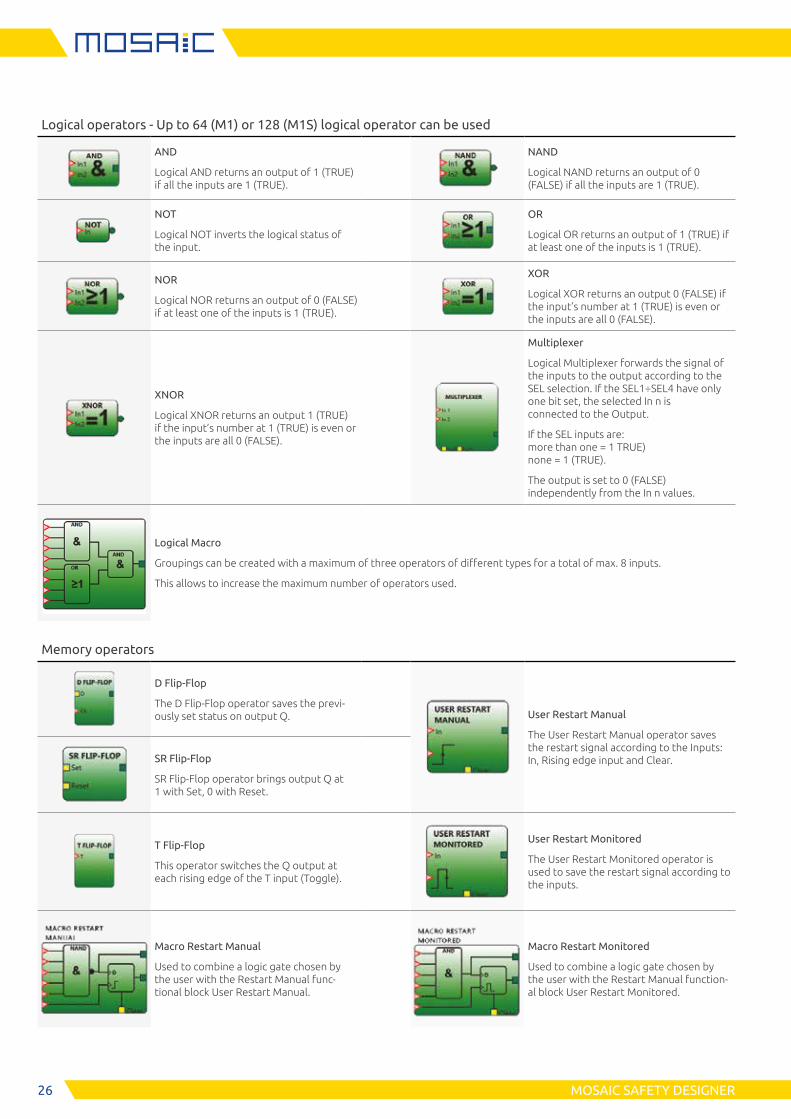
Logical operators - Up to 64 (M1) or 128 (M1S) logical operator can be used
AND
Logical AND returns an output of 1 (TRUE) if all the inputs are 1 (TRUE).
NAND
Logical NAND returns an output of 0 (FALSE) if all the inputs are 1 (TRUE).
NOT
Logical NOT inverts the logical status of the input.
OR
Logical OR returns an output of 1 (TRUE) if at least one of the inputs is 1 (TRUE).
NOR
Logical NOR returns an output of 0 (FALSE) if at least one of the inputs is 1 (TRUE).
XOR
Logical XOR returns an output 0 (FALSE) if the input’s number at 1 (TRUE) is even or the inputs are all 0 (FALSE).
XNOR
Logical XNOR returns an output 1 (TRUE) if the input’s number at 1 (TRUE) is even or the inputs are all 0 (FALSE).
Multiplexer
Logical Multiplexer forwards the signal of the inputs to the output according to the SEL selection. If the SEL1÷SEL4 have only one bit set, the selected In n is connected to the Output.
If the SEL inputs are: more than one = 1 TRUE) none = 1 (TRUE).
The output is set to 0 (FALSE) independently from the In n values.
Logical Macro
Groupings can be created with a maximum of three operators of different types for a total of max. 8 inputs.
This allows to increase the maximum number of operators used.
Memory operators
D Flip-Flop
The D Flip-Flop operator saves the previ-ously set status on output Q. User Restart Manual
The User Restart Manual operator saves the restart signal according to the Inputs: In, Rising edge input and Clear.SR Flip-Flop
SR Flip-Flop operator brings output Q at 1 with Set, 0 with Reset.
T Flip-Flop
This operator switches the Q output at each rising edge of the T input (Toggle).
User Restart Monitored
The User Restart Monitored operator is used to save the restart signal according to the inputs.
Macro Restart Manual
Used to combine a logic gate chosen by the user with the Restart Manual func-tional block User Restart Manual.
Macro Restart Monitored
Used to combine a logic gate chosen by the user with the Restart Manual function-al block User Restart Monitored.
27MOSAIC SAFETY DESIGNER
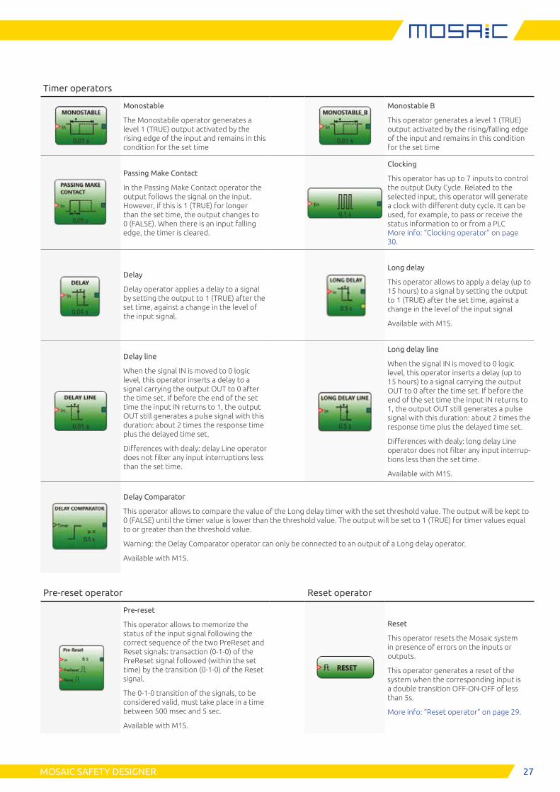
Timer operators
Monostable
The Monostabile operator generates a level 1 (TRUE) output activated by the rising edge of the input and remains in this condition for the set time
Monostable B
This operator generates a level 1 (TRUE) output activated by the rising/falling edge of the input and remains in this condition for the set time
Passing Make Contact
In the Passing Make Contact operator the output follows the signal on the input. However, if this is 1 (TRUE) for longer than the set time, the output changes to 0 (FALSE). When there is an input falling edge, the timer is cleared.
Clocking
This operator has up to 7 inputs to control the output Duty Cycle. Related to the selected input, this operator will generate a clock with different duty cycle. It can be used, for example, to pass or receive the status information to or from a PLC More info: “Clocking operator” on page 30.
Delay
Delay operator applies a delay to a signal by setting the output to 1 (TRUE) after the set time, against a change in the level of the input signal.
Long delay
This operator allows to apply a delay (up to 15 hours) to a signal by setting the output to 1 (TRUE) after the set time, against a change in the level of the input signal
Available with M1S.
Delay line
When the signal IN is moved to 0 logic level, this operator inserts a delay to a signal carrying the output OUT to 0 after the time set. If before the end of the set time the input IN returns to 1, the output OUT still generates a pulse signal with this duration: about 2 times the response time plus the delayed time set.
Differences with dealy: delay Line operator does not filter any input interruptions less than the set time.
Long delay line
When the signal IN is moved to 0 logic level, this operator inserts a delay (up to 15 hours) to a signal carrying the output OUT to 0 after the time set. If before the end of the set time the input IN returns to 1, the output OUT still generates a pulse signal with this duration: about 2 times the response time plus the delayed time set.
Differences with dealy: long delay Line operator does not filter any input interrup-tions less than the set time.
Available with M1S.
Delay Comparator
This operator allows to compare the value of the Long delay timer with the set threshold value. The output will be kept to 0 (FALSE) until the timer value is lower than the threshold value. The output will be set to 1 (TRUE) for timer values equal to or greater than the threshold value.
Warning: the Delay Comparator operator can only be connected to an output of a Long delay operator.
Available with M1S.
Pre-reset operator Reset operator
Pre-reset
This operator allows to memorize the status of the input signal following the correct sequence of the two PreReset and Reset signals: transaction (0-1-0) of the PreReset signal followed (within the set time) by the transition (0-1-0) of the Reset signal.
The 0-1-0 transition of the signals, to be considered valid, must take place in a time between 500 msec and 5 sec.
Available with M1S.
Reset
This operator resets the Mosaic system in presence of errors on the inputs or outputs.
This operator generates a reset of the system when the corresponding input is a double transition OFF-ON-OFF of less than 5s.
More info: “Reset operator” on page 29.
28 MOSAIC SAFETY DESIGNER
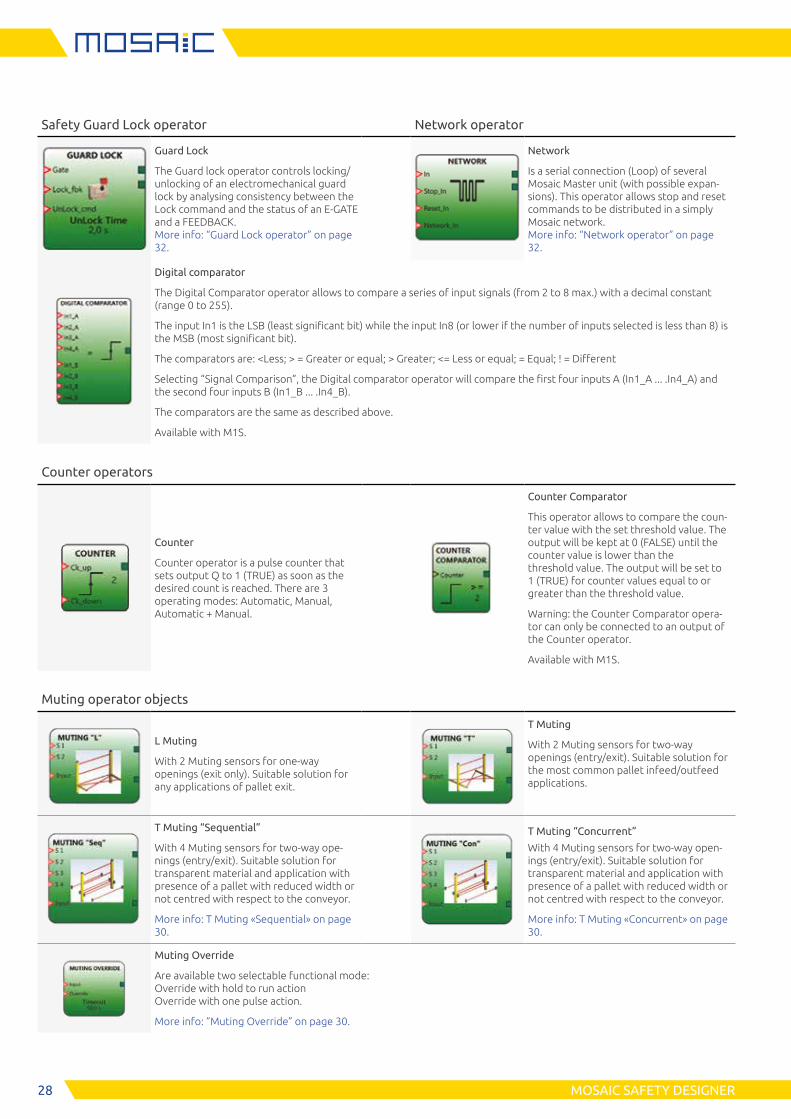
Safety Guard Lock operator Network operator
Guard Lock
The Guard lock operator controls locking/unlocking of an electromechanical guard lock by analysing consistency between the Lock command and the status of an E-GATE and a FEEDBACK. More info: “Guard Lock operator” on page 32.
Network
Is a serial connection (Loop) of several Mosaic Master unit (with possible expan-sions). This operator allows stop and reset commands to be distributed in a simply Mosaic network. More info: “Network operator” on page 32.
Digital comparator
The Digital Comparator operator allows to compare a series of input signals (from 2 to 8 max.) with a decimal constant (range 0 to 255).
The input In1 is the LSB (least significant bit) while the input In8 (or lower if the number of inputs selected is less than 8) is the MSB (most significant bit).
The comparators are: <Less; > = Greater or equal; > Greater; <= Less or equal; = Equal; ! = Different
Selecting “Signal Comparison”, the Digital comparator operator will compare the first four inputs A (In1_A ... .In4_A) and the second four inputs B (In1_B ... .In4_B).
The comparators are the same as described above.
Available with M1S.
Counter operators
Counter
Counter operator is a pulse counter that sets output Q to 1 (TRUE) as soon as the desired count is reached. There are 3 operating modes: Automatic, Manual, Automatic + Manual.
Counter Comparator
This operator allows to compare the coun-ter value with the set threshold value. The output will be kept at 0 (FALSE) until the counter value is lower than the threshold value. The output will be set to 1 (TRUE) for counter values equal to or greater than the threshold value.
Warning: the Counter Comparator opera-tor can only be connected to an output of the Counter operator.
Available with M1S.
Muting operator objects
L Muting
With 2 Muting sensors for one-way openings (exit only). Suitable solution for any applications of pallet exit.
T Muting
With 2 Muting sensors for two-way openings (entry/exit). Suitable solution for the most common pallet infeed/outfeed applications.
T Muting “Sequential”
With 4 Muting sensors for two-way ope-nings (entry/exit). Suitable solution for transparent material and application with presence of a pallet with reduced width or not centred with respect to the conveyor.
More info: T Muting «Sequential» on page 30.
T Muting “Concurrent”
With 4 Muting sensors for two-way open-ings (entry/exit). Suitable solution for transparent material and application with presence of a pallet with reduced width or not centred with respect to the conveyor.
More info: T Muting «Concurrent» on page 30.
Muting Override
Are available two selectable functional mode: Override with hold to run action Override with one pulse action.
More info: “Muting Override” on page 30.
29MOSAIC SAFETY DESIGNER
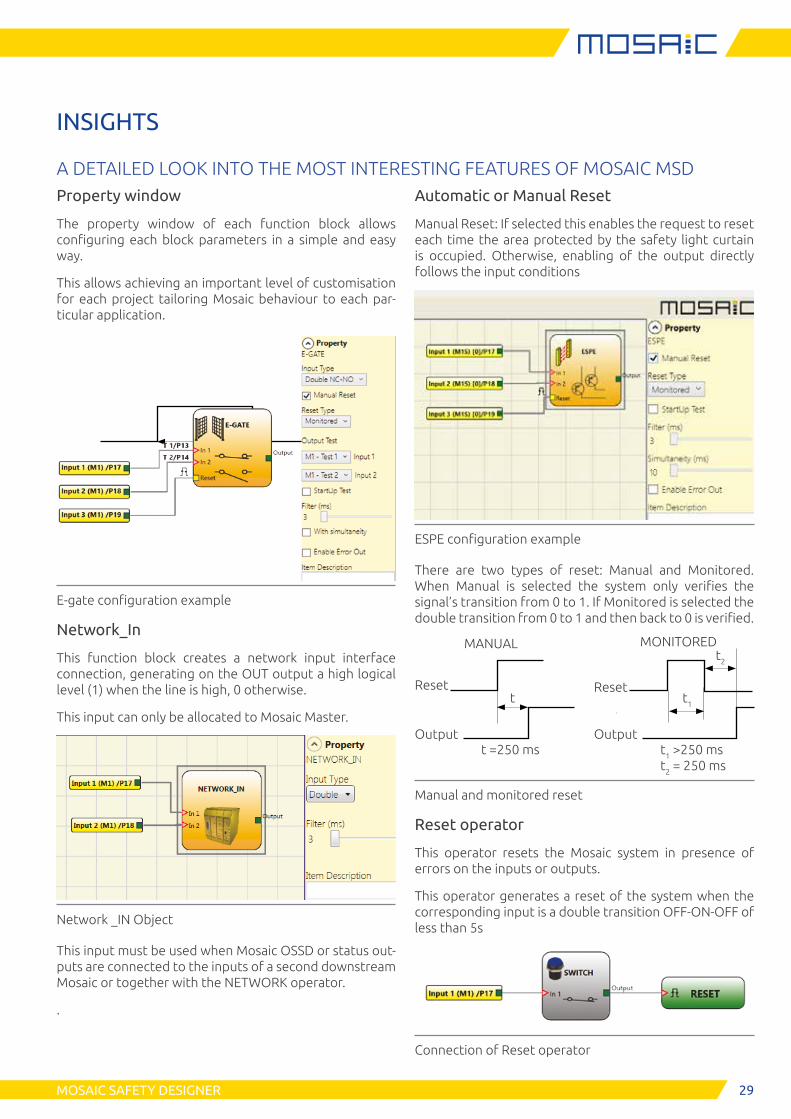
INSIGHTS
A DETAILED LOOK INTO THE MOST INTERESTING FEATURES OF MOSAIC MSDAutomatic or Manual Reset
Manual Reset: If selected this enables the request to reset each time the area protected by the safety light curtain is occupied. Otherwise, enabling of the output directly follows the input conditions
ESPE configuration example
There are two types of reset: Manual and Monitored. When Manual is selected the system only verifies the signal’s transition from 0 to 1. If Monitored is selected the double transition from 0 to 1 and then back to 0 is verified.
Reset
Output
t
t =250 ms
MANUAL
Reset
Output
t1
t1 >250 ms t2 = 250 ms
MONITOREDt2
Manual and monitored reset
Reset operator
This operator resets the Mosaic system in presence of errors on the inputs or outputs.
This operator generates a reset of the system when the corresponding input is a double transition OFF-ON-OFF of less than 5s
Connection of Reset operator
Property window
The property window of each function block allows configuring each block parameters in a simple and easy way.
This allows achieving an important level of customisation for each project tailoring Mosaic behaviour to each par-ticular application.
E-gate configuration example
Network_In
This function block creates a network input interface connection, generating on the OUT output a high logical level (1) when the line is high, 0 otherwise.
This input can only be allocated to Mosaic Master.
Network _IN Object
This input must be used when Mosaic OSSD or status out-puts are connected to the inputs of a second downstream Mosaic or together with the NETWORK operator.
.
30 MOSAIC SAFETY DESIGNER
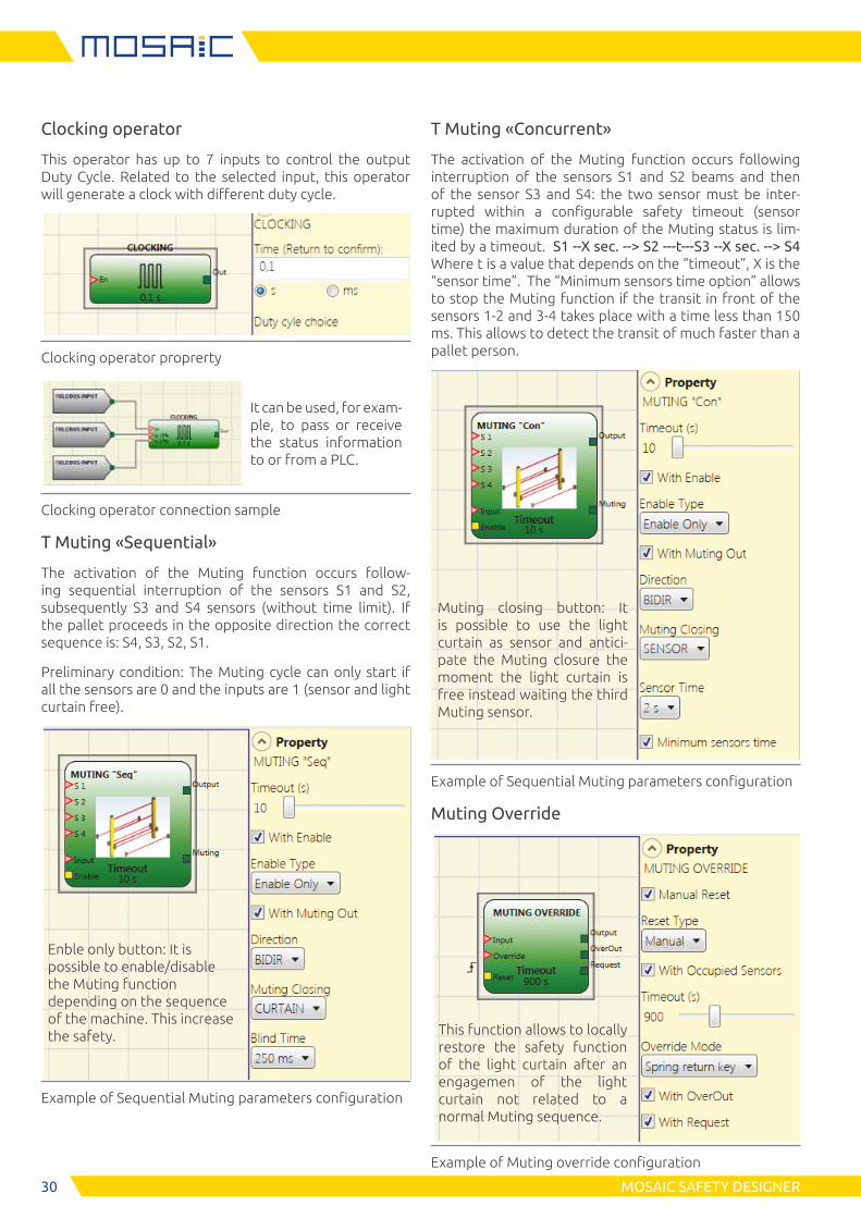
Clocking operator
This operator has up to 7 inputs to control the output Duty Cycle. Related to the selected input, this operator will generate a clock with different duty cycle.
Clocking operator proprerty
Clocking operator connection sample
T Muting «Sequential»
The activation of the Muting function occurs follow-ing sequential interruption of the sensors S1 and S2, subsequently S3 and S4 sensors (without time limit). If the pallet proceeds in the opposite direction the correct sequence is: S4, S3, S2, S1.
Preliminary condition: The Muting cycle can only start if all the sensors are 0 and the inputs are 1 (sensor and light curtain free).
Example of Sequential Muting parameters configuration
T Muting «Concurrent»
The activation of the Muting function occurs following interruption of the sensors S1 and S2 beams and then of the sensor S3 and S4: the two sensor must be inter-rupted within a configurable safety timeout (sensor time) the maximum duration of the Muting status is lim-ited by a timeout. S1 --X sec. --> S2 ---t---S3 --X sec. --> S4 Where t is a value that depends on the “timeout”, X is the “sensor time”. The “Minimum sensors time option” allows to stop the Muting function if the transit in front of the sensors 1-2 and 3-4 takes place with a time less than 150 ms. This allows to detect the transit of much faster than a pallet person.
Example of Sequential Muting parameters configuration
Muting Override
Example of Muting override configuration
Enble only button: It is possible to enable/disable the Muting function depending on the sequence of the machine. This increase the safety.
It can be used, for exam-ple, to pass or receive the status information to or from a PLC.
Muting closing button: It is possible to use the light curtain as sensor and antici-pate the Muting closure the moment the light curtain is free instead waiting the third Muting sensor.
This function allows to locally restore the safety function of the light curtain after an engagemen of the light curtain not related to a normal Muting sequence.
31MOSAIC SAFETY DESIGNER
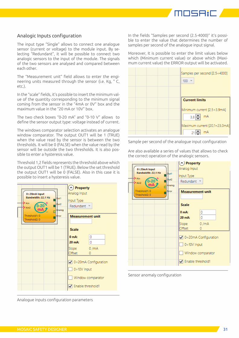
Analogic Inputs configuration
The input type “Single” allows to connect one analogue sensor (current or voltage) to the module input. By se-lecting “Redundant”, it will be possible to connect two analogic sensors to the input of the module. The signals of the two sensors are analysed and compared between each other.
The “Measurement unit” field allows to enter the engi-neering units measured through the sensor (i.e. Kg, ° C, etc.).
In the “scale” fields, it’s possible to insert the minimum val-ue of the quantity corresponding to the minimum signal coming from the sensor in the “4mA or 0V” box and the maximum value in the “20 mA or 10V” box.
The two check boxes “0-20 mA” and “0-10 V” allows to define the sensor output type: voltage instead of current.
The windows comparator selection activates an analogue window comparator. The output OUT1 will be 1 (TRUE) when the value read by the sensor is between the two thresholds. It will be 0 (FALSE) when the value read by the sensor will be outside the two thresholds. It is also pos-sible to enter a hysteresis value.
Threshold 1,2 fields represents the threshold above which the output OUT1 will be 1 (TRUE). Below the set threshold the output OUT1 will be 0 (FALSE). Also in this case it is possible to insert a hysteresis value.
Analogue inputs configuration parameters
In the fields “Samples per second (2.5-4000)” it’s possi-ble to enter the value that determines the number of samples per second of the analogue input signal.
Moreover, It is possible to enter the limit values below which (Minimum current value) or above which (Maxi-mum current value) the ERROR output will be activated.
Sample per second of the analogue input configuration
Are also available a series of values that allows to check the correct operation of the analogic sensors.
Sensor anomaly configuration
32 MOSAIC SAFETY DESIGNER
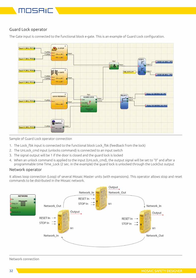
Guard Lock operator
The Gate input is connected to the functional block e-gate. This is an example of Guard Lock configuration.
Sample of Guard Lock operator connection
1. The Lock_fbk input is connected to the functional block Lock_fbk (feedback from the lock)
2. The UnLock_cmd input (unlocks command) is connected to an input switch
3. The signal output will be 1 if the door is closed and the guard lock is locked
4. When an unlock command is applied to the input (UnLock_cmd), the output signal will be set to “0” and after a programmable time Time_Lock (2 sec. in the example) the guard lock is unlocked through the LockOut output
Network operator
It allows loop connection (Loop) of several Mosaic Master units (with expansions). This operator allows stop and reset commands to be distributed in the Mosaic network.
Network connection
33MOSAIC SAFETY DESIGNER
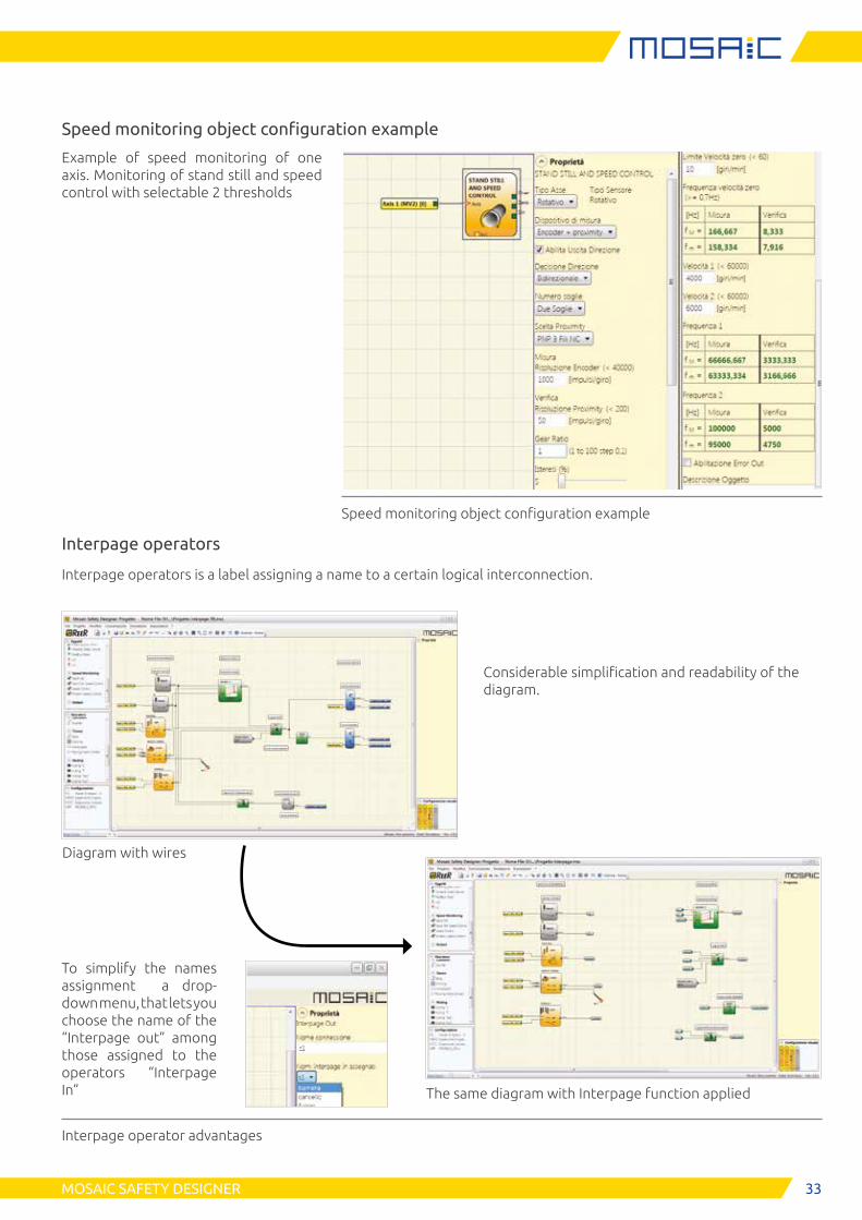
Speed monitoring object configuration example
Example of speed monitoring of one axis. Monitoring of stand still and speed control with selectable 2 thresholds
Speed monitoring object configuration example
Interpage operators
Interpage operators is a label assigning a name to a certain logical interconnection.
Interpage operator advantages
Diagram with wires
Considerable simplification and readability of the diagram.
To simplify the names assignment a drop-down menu, that lets you choose the name of the “Interpage out” among those assigned to the operators “Interpage In” The same diagram with Interpage function applied
34 MOSAIC SAFETY DESIGNER
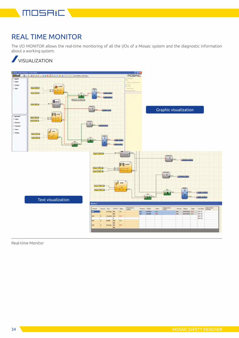
REAL TIME MONITORThe I/O MONITOR allows the real-time monitoring of all the I/Os of a Mosaic system and the diagnostic information about a working system.
VISUALIZATION
Text visualization
Real-time Monitor
Graphic visualization
35MOSAIC SAFETY DESIGNER
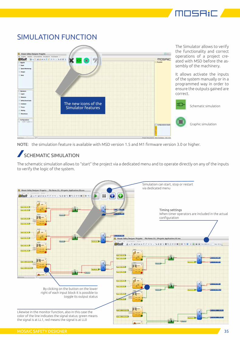
SIMULATION FUNCTIONThe Simulator allows to verify the functionality and correct operations of a project cre-ated with MSD before the as-sembly of the machinery.
It allows activate the inputs of the system manually or in a programmed way in order to ensure the outputs gained are correct.
Schematic simulation
Graphic simulation
The new icons of the Simulator features
NOTE: the simulation feature is available with MSD version 1.5 and M1 firmware version 3.0 or higher.
SCHEMATIC SIMULATION
The schematic simulation allows to “start” the project via a dedicated menu and to operate directly on any of the inputs to verify the logic of the system.
Simulation can start, stop or restart via dedicated menu
By clicking on the button on the lower right of each input block it is possible to
toggle its output status
Likewise in the monitor function, also in this case the color of the line indicates the signal status: green means the signal is at LL1, red means the signal is at LL0
Timing settings When timer operators are included in the actual configuration
36 MOSAIC SAFETY DESIGNER
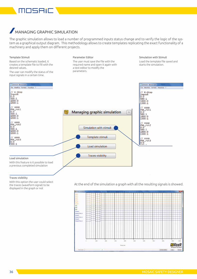
MANAGING GRAPHIC SIMULATION
The graphic simulation allows to load a number of programmed inputs status change and to verify the logic of the sys-tem as a graphical output diagram. This methodology allows to create templates replicating the exact functionality of a machinery and apply them on different projects.
Template Stimuli
Based on the schematic loaded, it creates a template file to fill with the desired values.
The user can modify the status of the input signals in a certain time.
Parameter Editor
The user must save the file with the required name and open it again with a text editor to modify the parameters.
Simulation with Stimuli
Load the template file saved and starts the simulation.
Load simulation
With this feature is it possible to load a previous completed simulation
Traces visibility
With this option the user could select the traces (waveform signal) to be displayed in the graph or not
At the end of the simulation a graph with all the resulting signals is showed.
37
1
2
HSD SOFTWARE
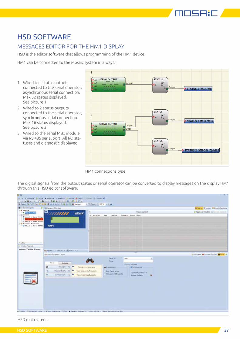
HSD SOFTWAREMESSAGES EDITOR FOR THE HM1 DISPLAYHSD is the editor software that allows programming of the HM1 device.
HM1 can be connected to the Mosaic system in 3 ways:
1. Wired to a status output connected to the serial operator, asynchronous serial connection. Max 32 status displayed. See picture 1
2. Wired to 2 status outputs connected to the serial operator, synchronous serial connection. Max 16 status displayed. See picture 2
3. Wired to the serial MBx module via RS 485 serial port, All I/O sta-tuses and diagnostic displayed
HM1 connections type
HSD main screen
The digital signals from the output status or serial operator can be converted to display messages on the display HM1 through this HSD editor software.
38 APPLICATION EXAMPLES
APPLICATION EXAMPLES
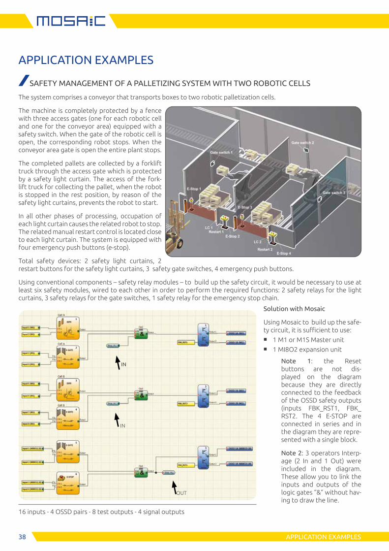
SAFETY MANAGEMENT OF A PALLETIZING SYSTEM WITH TWO ROBOTIC CELLS
The system comprises a conveyor that transports boxes to two robotic palletization cells.
The machine is completely protected by a fence with three access gates (one for each robotic cell and one for the conveyor area) equipped with a safety switch. When the gate of the robotic cell is open, the corresponding robot stops. When the conveyor area gate is open the entire plant stops.
The completed pallets are collected by a forklift truck through the access gate which is protected by a safety light curtain. The access of the fork-lift truck for collecting the pallet, when the robot is stopped in the rest position, by reason of the safety light curtains, prevents the robot to start.
In all other phases of processing, occupation of each light curtain causes the related robot to stop. The related manual restart control is located close to each light curtain. The system is equipped with four emergency push buttons (e-stop).
Total safety devices: 2 safety light curtains, 2 restart buttons for the safety light curtains, 3 safety gate switches, 4 emergency push buttons.
Using conventional components – safety relay modules – to build up the safety circuit, it would be necessary to use at least six safety modules, wired to each other in order to perform the required functions: 2 safety relays for the light curtains, 3 safety relays for the gate switches, 1 safety relay for the emergency stop chain.
IN
IN
OUT
Solution with Mosaic
Using Mosaic to build up the safe-ty circuit, it is sufficient to use:
■ 1 M1 or M1S Master unit ■ 1 MI8O2 expansion unit
Note 1: the Reset buttons are not dis-played on the diagram because they are directly connected to the feedback of the OSSD safety outputs (inputs FBK_RST1, FBK_RST2. The 4 E-STOP are connected in series and in the diagram they are repre-sented with a single block.
Note 2: 3 operators Interp-age (2 In and 1 Out) were included in the diagram. These allow you to link the inputs and outputs of the logic gates “&” without hav-ing to draw the line.
16 inputs - 4 OSSD pairs - 8 test outputs - 4 signal outputs
39APPLICATION EXAMPLES
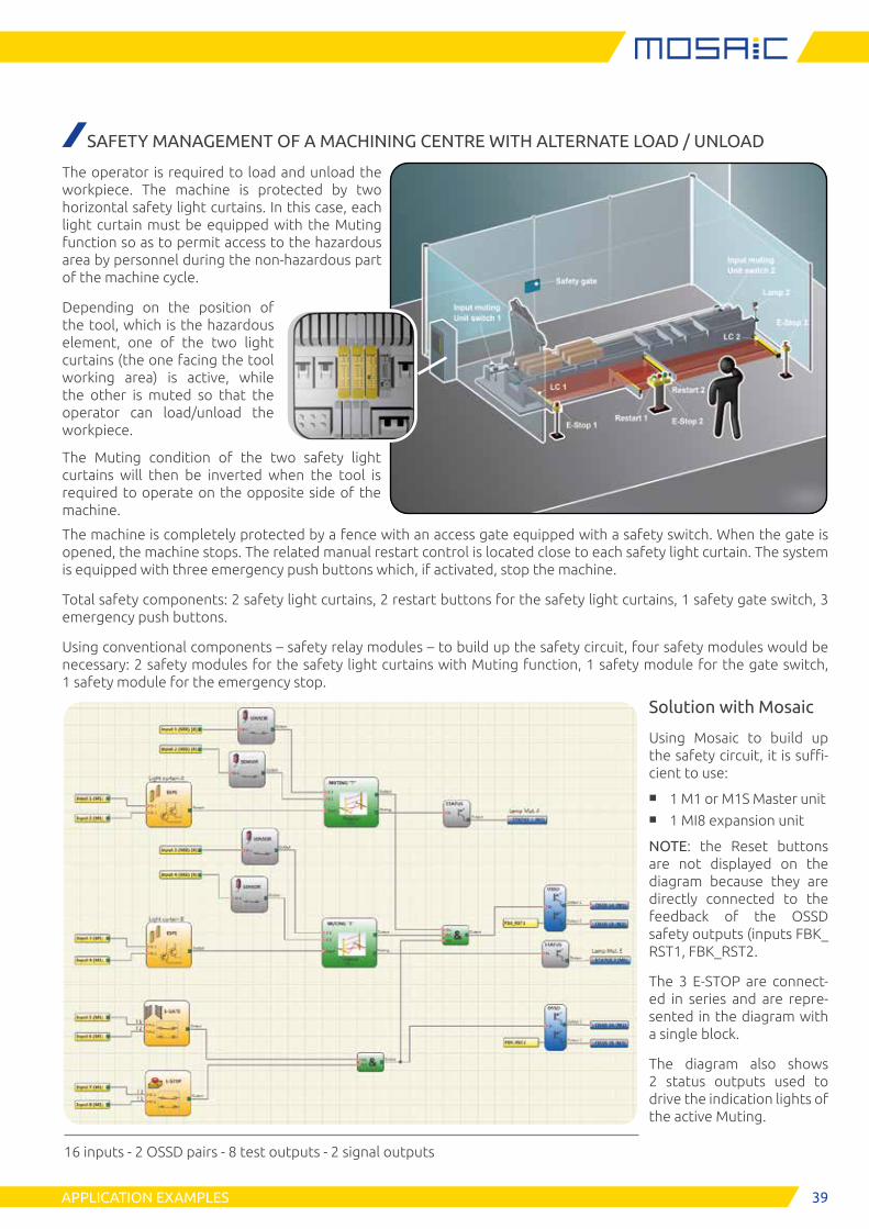
SAFETY MANAGEMENT OF A MACHINING CENTRE WITH ALTERNATE LOAD / UNLOAD
The operator is required to load and unload the workpiece. The machine is protected by two horizontal safety light curtains. In this case, each light curtain must be equipped with the Muting function so as to permit access to the hazardous area by personnel during the non-hazardous part of the machine cycle.
Depending on the position of the tool, which is the hazardous element, one of the two light curtains (the one facing the tool working area) is active, while the other is muted so that the operator can load/unload the workpiece.
The Muting condition of the two safety light curtains will then be inverted when the tool is required to operate on the opposite side of the machine.
The machine is completely protected by a fence with an access gate equipped with a safety switch. When the gate is opened, the machine stops. The related manual restart control is located close to each safety light curtain. The system is equipped with three emergency push buttons which, if activated, stop the machine.
Total safety components: 2 safety light curtains, 2 restart buttons for the safety light curtains, 1 safety gate switch, 3 emergency push buttons.
Using conventional components – safety relay modules – to build up the safety circuit, four safety modules would be necessary: 2 safety modules for the safety light curtains with Muting function, 1 safety module for the gate switch, 1 safety module for the emergency stop.
Solution with Mosaic
Using Mosaic to build up the safety circuit, it is suffi-cient to use:
■ 1 M1 or M1S Master unit ■ 1 MI8 expansion unit
NOTE: the Reset buttons are not displayed on the diagram because they are directly connected to the feedback of the OSSD safety outputs (inputs FBK_RST1, FBK_RST2.
The 3 E-STOP are connect-ed in series and are repre-sented in the diagram with a single block.
The diagram also shows 2 status outputs used to drive the indication lights of the active Muting.
16 inputs - 2 OSSD pairs - 8 test outputs - 2 signal outputs
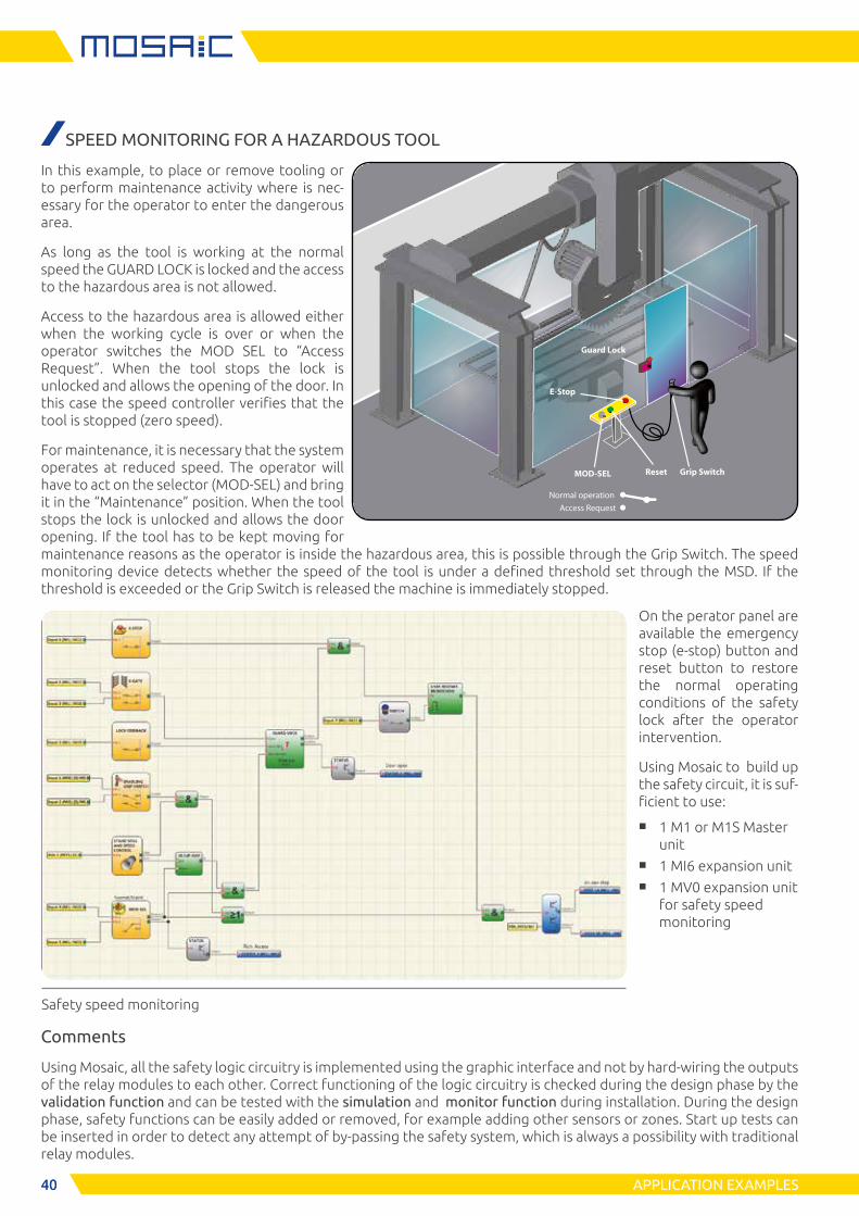
4040
Access Request
MOD-SEL Reset
E-Stop
Grip Switch
Guard Lock
Normal operation
APPLICATION EXAMPLES
Safety speed monitoring
SPEED MONITORING FOR A HAZARDOUS TOOL
In this example, to place or remove tooling or to perform maintenance activity where is nec-essary for the operator to enter the dangerous area.
As long as the tool is working at the normal speed the GUARD LOCK is locked and the access to the hazardous area is not allowed.
Access to the hazardous area is allowed either when the working cycle is over or when the operator switches the MOD SEL to “Access Request”. When the tool stops the lock is unlocked and allows the opening of the door. In this case the speed controller verifies that the tool is stopped (zero speed).
For maintenance, it is necessary that the system operates at reduced speed. The operator will have to act on the selector (MOD-SEL) and bring it in the “Maintenance” position. When the tool stops the lock is unlocked and allows the door opening. If the tool has to be kept moving for maintenance reasons as the operator is inside the hazardous area, this is possible through the Grip Switch. The speed monitoring device detects whether the speed of the tool is under a defined threshold set through the MSD. If the threshold is exceeded or the Grip Switch is released the machine is immediately stopped.
On the perator panel are available the emergency stop (e-stop) button and reset button to restore the normal operating conditions of the safety lock after the operator intervention.
Using Mosaic to build up the safety circuit, it is suf-ficient to use:
■ 1 M1 or M1S Master unit
■ 1 MI6 expansion unit ■ 1 MV0 expansion unit
for safety speed monitoring
Comments
Using Mosaic, all the safety logic circuitry is implemented using the graphic interface and not by hard-wiring the outputs of the relay modules to each other. Correct functioning of the logic circuitry is checked during the design phase by the validation function and can be tested with the simulation and monitor function during installation. During the design phase, safety functions can be easily added or removed, for example adding other sensors or zones. Start up tests can be inserted in order to detect any attempt of by-passing the safety system, which is always a possibility with traditional relay modules.
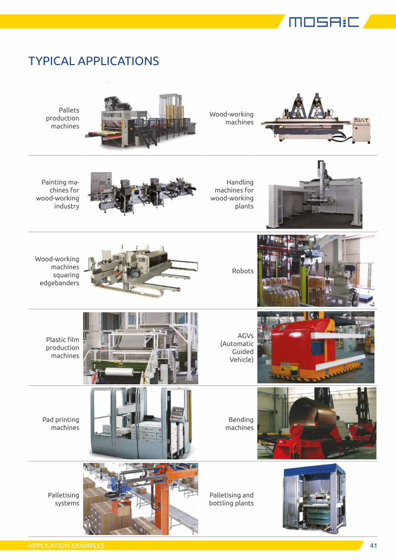
41APPLICATION EXAMPLES
TYPICAL APPLICATIONS
Pallets production
machines
Wood-working machines
Painting ma-chines for
wood-working industry
Handling machines for
wood-working plants
Wood-working machines squaring
edgebanders
Robots
Plastic film production
machines
AGVs (Automatic
Guided Vehicle)
Pad printing machines
Bending machines
Palletising systems
Palletising and bottling plants

4242 APPLICATION EXAMPLES
Elevators
Crate packer/unpa-
cker and palletising
systems
Beam drilling and sawing
machines
Panel sizing saws
Vertical lift storage system
Rail dependent storage and
retrieval equipment
Industrial boilers
Industrial thermal
processes
Wood working CNC
Cutting tables for glass
Industrial plant
application with MA2 and MA4 Analogic imput unit:
Loading cells (weight, compression and traction measurements), pressure switches, temperature measurements, flow measurements, level measu-
rements, etc.

43
We put our Customers always first
ReeR after sales service is committed to support all customers that need technical guidance regarding functionality, handling and installation of our products.
Customer Service Hotline +39 011 24 82 215
Monday to Friday 8.30 - 12.30 and 13.30-18.00 (CET)
or contact [email protected]
For product returns please visit www.reersafety.com for further information.
CUSTOMER SERVICE
ReeR SpA Via Carcano, 32 10153 Torino, Italy T +39 011 248 2215F +39 011 859 867
More than 60 years of quality and innovation
Founded in Turin (Italy) in 1959, ReeR distinguished itself for its strong commitment to innovation and technology.
A steady growth throughout the years allowed ReeR to become a point of reference in the safety automation in-dustry at a worldwide level.
The Safety Division is in fact today a world leader in the development and manufacturing of safety optoelectronic sensors and controllers.
ReeR is ISO 9001, ISO 14001 and ISO 45001 certified.
Made in Italysince 1959
www.reersafety.com | [email protected]
ReeR SpA does not guarantee that product information in this catalogue are the most current available. ReeR SpA reserves the right to make changes to the products described without notice and assumes no liability as a result of their use or application. Our goal is to keep the information on this catalogue timely and accurate, however ReeR SpA accepts no responsibility or liability whatsoever with regard to the information on this catalogue. Reproduction is not authorised, except with the expressed permission of ReeR SpA.
Issue 2 - Rev. 1.5 April 2020
8946225MOSAIC - English
Printed in Italy