Embed Size (px)
Citation preview

Modular Nanosatellites as Amateur Radio Communication Platforms
Funded by the
New Hampshire Space Grant Consortium
Gus Moore; Todd Kerner, KB2BCT; Amish Parashar, KE6EZM

Project Concept
• Modularity by Design
• A functional bus module providing Power, Control, Communications
• Platform for Single-Purpose Research
• Compatibility with other University Programs
• Incremental Development

Evolution of DARTSAT
“Student Initiated, Student Designed, Faculty Mentored”
• Conceived Fall ‘99 as Amateur Radio Communications Satellite
• Desired Experimental Capabilities
“A Modular Approach
to Space Access”
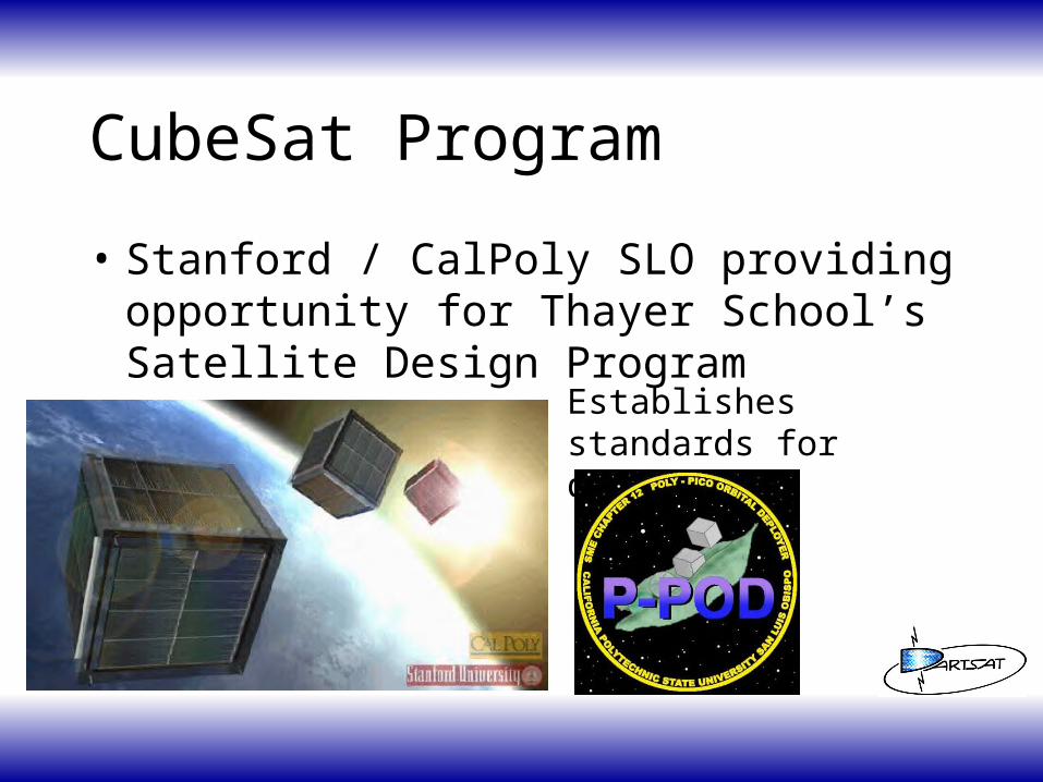
CubeSat Program
• Stanford / CalPoly SLO providing opportunity for Thayer School’s Satellite Design Program
Establishes standards for design

DARTSAT Specifications
• 10 cm cube pre-release, < 1 kg
• 1 year functional life
• Amateur radio communication
• < $10,000 System Bus
• Capability to support a wide variety of experiments at any time
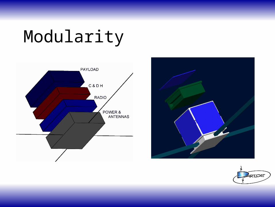
Modularity

Low Earth Orbit

Functional Block Diagram

DARTSAT Functions
• CPU– FM repeater (J-mode)– DTMF control– Analog Measurements– Morse Code ID
• Data Acquisition– Temperature– Solar Cell Power– Battery Status– Magnetic Fields (Orientation)

Power
• Batteries– 4.8V, 2A NiCds
• Solar Panels– 6.0V, 200 mA
• Distribution– Passive Diodes

Radio Specifications
• Receiver: 144 MHz uplink– Motorola MC13136– FM, 1 uV sensitivity, 5 kHz bandwidth– 3.8 VDC, 50 mA Operation
• Transmitter: 440 MHz download– Motorola MC13176, RF2117 Amplifier– FM, 125 to 500 mW RF Output, 5 kHz BW– 3.8 VDC, 500 mA max operation

Antennas •Perpendicular Dipoles for Transmitter & Receiver
•0 dB Gain
•Omni directional since satellite is not stabilized
•Using circularly polarized, high gain antennas on ground
•Antenna deployment once space borne
Unique Challenges• Wide Temperature Oscillation
-40 to +50 C
• Limited Power • Physically small package
– SMT all parts if necessary
• Extreme Vibrations high spin rates not stabilized
• Radiation Issues little mass protecting the circuitry

Testing DARTSAT
• Conducted at Lockheed / Sanders– Temperature– Vacuum– Vibration– Electrical Interference– Charging Case– Radiation Hardness

DARTSAT Status• Satellite Design Complete
– Radios– Mechanical– Power– Control
• Prototype complete – January 2001• Testing – February 2001• Flight unit – March 2001
Conclusions
• New student program, inaugural to Dartmouth Space Programs
• Provides a link between Amateur Radio and Academic Communities
• Future– Standardized Bus Plug and Play Science
Experiments– Constellations Low cost, large area
communications

Recognition
• New Hampshire Space Grant Consortium
• Lockheed Sanders
• Stanford / CalPoly
• Apple Computer
• Thayer School and Dartmouth College Alumni