Embed Size (px)
Citation preview
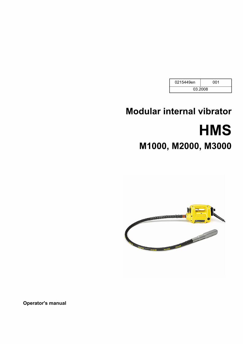
Modular internal vibrator
HMSM1000, M2000, M3000
0215449en 001
03.2008
Operator's manual

M1000, M2000, M3000 Contents
3
1 Foreword .................................................................................................................... 5
2 Introduction ............................................................................................................... 62.1 Means of representation for this operator's manual ........................................... 62.2 WACKER representative .................................................................................... 72.3 Described machine parts.................................................................................... 7
3 Safety information .................................................................................................... 83.1 Principle.............................................................................................................. 83.2 Qualification of the operating personnel ........................................................... 113.3 Protective gear ................................................................................................. 113.4 Transport .......................................................................................................... 123.5 Operating safety ............................................................................................... 123.6 Safety during the operation of electric appliances............................................ 133.7 Maintenance..................................................................................................... 153.8 Safety labels ..................................................................................................... 15
4 Scope of delivery .................................................................................................... 16
5 Description .............................................................................................................. 175.1 Application........................................................................................................ 175.2 Functionality ..................................................................................................... 175.3 Drive components and operator's controls ....................................................... 185.4 Flexible shaft components................................................................................ 195.5 Vibrator head components ............................................................................... 19
6 Transport ................................................................................................................. 20
7 Operation ................................................................................................................. 217.1 Prior to starting the machine............................................................................. 217.2 Mounting the vibrator head............................................................................... 227.3 Starting up ........................................................................................................ 247.4 Decomissioning ................................................................................................ 26
8 Maintenance ............................................................................................................ 288.1 Maintenance schedule...................................................................................... 298.2 Maintenance work ............................................................................................ 30
9 Troubleshooting ...................................................................................................... 39
10 Disposal ................................................................................................................... 4010.1 Disposal of the machine ................................................................................... 40
Inhalt
4
Contents M1000, M2000, M3000
11 Accessories ............................................................................................................. 4111.1 Special wrench for flexible shaft ....................................................................... 4111.2 Pipe thread seal ............................................................................................... 4111.3 Special lubricant for flexible shafts ................................................................... 4111.4 SS-adapter ....................................................................................................... 4111.5 Carrying belt ..................................................................................................... 41
12 Technical data ......................................................................................................... 4212.1 Drive ................................................................................................................. 4212.2 Noise and vibration figures............................................................................... 4312.3 Flexible shafts .................................................................................................. 4412.4 Vibrator head.................................................................................................... 4512.5 Notes regarding class rating and protection class............................................ 4612.6 Extension cable ................................................................................................ 4712.7 Allowable Drive - Flexible Shaft - Vibrator Head combinations ........................ 49
EC Declaration of Conformity ................................................................................ 51
UL Certificate ........................................................................................................... 53
DIN EN ISO 9001 Certificate ................................................................................... 55
Foreword
5
1 Foreword
This operator's manual contains information and procedures for the safe opera-tion and maintenance of your WACKER machine. In the interest of your own safety and to prevent accidents, you should carefully read through the safety in-formation, familiarize yourself with it and observe it at all times.This operator's manual is not a manual for extensive maintenance and repair work. Such work should be carried out by WACKER Service or authorized spe-cialists.
The safety of the operator was one of the most important aspects taken into con-sideration when this machine was designed. Nevertheless, improper use or in-correct maintenance can pose a risk. Please operate and maintain your WACKER machine in accordance with the instructions in this operator's manual. Your reward will be troublefree operation and a high degree of availability.
Defective machine parts must be replaced immediately!Please contact your WACKER representative if you have any questions con-cerning operation or maintenance.
All rights reserved, especially reproduction and distribution rights.Copyright 2008 Wacker Construction Equipment AG
No part of this publication may be reproduced in any form or by any means, elec-tronic or mechanical, including photocopying, without the expressed written per-mission of WACKER.Any type of reproduction, distribution or storage on data media of any type and form not authorized by WACKER represents an infringement of copyright and will be prosecuted. We expressly reserve the right to make technical modifications – even without special notice – which aim at further improving our machines or their safety stan-dards.
6
Introduction
2 Introduction
2.1 Means of representation for this operator's manual
Warning symbolsThis operator's manual contains safety imformation of the categories: DANGER, WARNING, CAUTION, NOTICE.They should be followed to prevent danger to life and limb or damage to equip-ment or improper service.
Notes
Note: Complementary information will be displayed here.
Instructions This symbol indicates there is something for you to do.
1. Numbered instructions indicate that you have to carry out something in a defined sequence.
This symbol is used for lists.
DANGERThis warning notice indicates hazards that result in serious injury or even death.
Danger can be avoided by the following the actions mentioned.
WARNINGThis warning notice indicates hazards that can result in serious injury or even death.
Danger can be avoided by the following the actions mentioned.
CAUTIONThis warning notice indicates hazards that can result in minor injury.
Danger can be avoided by the following the actions mentioned.
NOTICEThis warning notice indicates hazards that can result in material damage.
Danger can be avoided by the following the actions mentioned.
Introduction
7
2.2 WACKER representative
Depending on your country, your WACKER representative is your WACKER Service, your WACKER affiliate or your WACKER dealer.You can find the addresses in the Internet at www.wackergroup.com.The addresses of the WACKER main locations are located at the end of this op-erator's manual.
2.3 Described machine parts
This operator's manual is valid for different machine parts from a product range. Therefore some figures can differ from the actual appearance of your machine. It is also possible that the descriptions include components which are not a part of your machine. Details for the described machine types can be found in the chapter Technical Data.
8
Safety information M1000, M2000, M3000
3 Safety information
3.1 Principle
State of the artThis machine has been constructed with state-of-the-art technology according to the recognized rules of safety. Nevertheless, when used improperly, dangers to the life and limb of the operator or to third persons or damage to the machine or other materials cannot be excluded.
Proper useThe machine may only be used for compacting fresh concrete. The vibrator head has to be immersed in the fresh concrete.Its proper use also includes the observance of all instructions contained in this operator's manual as well as complying with the required service and mainte-nance instructions.Any other use is regarded as improper. Any damage resulting from improper use will void the warranty and the liability on behalf of the manufacturer. The operator assumes full responsibility.
Structural modificationsNever attempt to modify the machine without the written permission of the man-ufacturer. To do so will endanger your safety and the safety of other people! In addition, this will void the warranty and the liability on behalf of the manufacturer.Especially the following are cases of structural modifications:
Opening the machine and the permanent removal of components from WACKER.Installing new components which are not from WACKER and not equivalent to the original parts in design and quality.Installation of accessories which are not from WACKER.
It is no problem to install spare parts from WACKER.It is no problem to install accessories that are available in the WACKER product range of your machine. Please refer to the installation regulations in this opera-tor's manual.
Requirements for operationThe ability to operate the machine safely requires:
Proper transport, storage and setup.Careful operation.Careful service and maintenance.
M1000, M2000, M3000 Safety information
9
OperationOperate the machine only as intended and only when in proper working condi-tion.Operate the machine in a safety-conscious manner with all safety devices at-tached and enabled. Do not modify or disable any safety devices.Before starting operation, check that all control and safety devices are function-ing properly.Never operate the machine in a potentially explosive environment.
SupervisionNever leave the machine running unattended!
MaintenanceRegular maintenance is required in order for the machine to operate properly and reliably over time. Neglected maintenance work can make the machine danger-ous to use.
Strictly observe the prescribed maintenance intervals.Do not use the machine if it requires maintenance or repairs.
MalfunctionsIf you detect a malfunction, you must shut down and secure the machine imme-diately.Eliminate the malfunctions that impair safety immediately!Have damaged or defective components replaced immediately!For further information, refer to chapter Troubleshooting.
Spare parts, accessoriesOnly use spare parts and accessories from WACKER. Non-compliance will ex-empt the manufacturer from all liability.
Exclusion of liabilityWACKER will refuse to accept liability for injuries to persons or for damage to materials in the following cases:
Structural modifications.Improper use.Improper handling.Use of spare parts and accessories not produced by WACKER.
10
Safety information M1000, M2000, M3000
Operator's manualAlways keep the operator's manual near the machine or near the worksite for quick reference. If you have misplaced the operator's manual or require an additional copy, con-tact your WACKER representative or download it from the Internet (www.wackergroup.com).Always hand over this operator's manual to other operators or to the future owner of the machine.
Country-specific regulationsObserve the country-specific regulations, standards and guidelines in reference to accident prevention and environmental safety, for example those pertaining to hazardous materials and wearing protective gear.Complement the operator's manual with additional instructions taking into ac-count the operational, regulatory, national or generally applicable safety guide-lines.
Operator's controlsAlways keep the operator's controls of the machine dry, clean and free of oil or grease.The function of the operator's controls must not be manipulated or rendered in-effective.
CleaningAlways keep the machine clean and be sure to clean it each time you have fin-ished using it.Do not use gasoline or solvents. Danger of explosion!
Checking for signs of damageInspect the machine when it is switched off for any signs of damage at least once per work shift.Do not start the machine if there is visible damage or defects.Have any damage or defects eliminated immediately.
M1000, M2000, M3000 Safety information
11
3.2 Qualification of the operating personnel
Operator qualificationsOnly trained personnel are permitted to start and operate the machine. The fol-lowing rules also apply:
You are physically and mentally fit.You have received instruction on how to independently use the machine.You have received instruction in the proper use of the machine.You are familiar with required safety devices.You are authorized to start machines and systems in accordance with the standards governing safety.You have been assigned to work on the machine by your company.
Incorrect operationIncorrect operation or misuse by untrained personnel can endanger the health and safety of the operator and also cause machine and material damage.
Operating company responsibilitiesThe operating company must make the operator's manual available to the oper-ator and ensure that the operator has read and understood it.
Work recommendationsPlease observe the recommendations below:
Work only if you are in a good physical condition.Work attentively, particularly as you finish.Do not operate the machine when you are tired.Carry out all work calmly, circumspectly and carefully.Never operate the machine under the influence of alcohol, drugs or medica-tion. This can impair your vision, reactions and your judgment.Work in a manner that does not endanger others.
3.3 Protective gear
Work clothingClothing should be appropriate, i.e. should be close-fitting but not restrict your movement.When on construction sites, do not wear long hair loosely, loose clothing or jew-elry including rings. These objects can easily get caught or be drawn in by mov-ing machine parts.
12
Safety information M1000, M2000, M3000
Personal protective gearWear personal protective gear to avoid injuries or health hazards:
Non-skid, hard-toed shoes.Work gloves made of durable material.Overalls made of durable material.Hard hat.Ear protection.
Ear protectionThis machine generates noise that exceeds the country-specific permissible noise levels (individual rating level). It may therefore be necessary to wear ear protection. You can find the exact value in the chapter Technical Data.WACKER recommends that you always wear ear protection.
3.4 Transport
Switching off the machineBefore you transport the machine, switch it off and pull the plug out of the plug receptacle. Allow the motor to cool down.
Transporting the machineSecure the machine on the transport device against tilting, falling or slipping.
RestartingMachines, machine parts, accessories or tools that were detached for transport purposes must be re-mounted and fastened before restarting.Only operate in accordance with the operating instructions.
3.5 Operating safety
Work environmentFamiliarize yourself with your work environment before you start work. This in-cludes e.g. the following items:
Obstacles in the work and traffic area.Load-carrying capacity of the ground.The measures needed to cordon off the construction site from public traffic.The measures needed to secure walls and ceilings.Options available in the event of an accident.
Starting the machineObserve the safety information and warning notices located on the machine.Never attempt to switch on a machine that requires maintenance or repairs.Switch on the machine as directed in the operator's manual.
M1000, M2000, M3000 Safety information
13
Vertical stabilityAlways make sure that you stand firmly when working with the machine. This ap-plies particularly when working on scaffoldings, ladders, etc.
Switching off the machineSwitch off the machine and pull the plug out of the plug receptacle in the following situations:
Before breaks.If you are not using the machine.
Store the machine or put it down in such a way that it cannot tilt, fall down or slip.
StorageStore the machine or put it down in such a way that it cannot tilt, fall down or slip.
Storage locationStore the machine after operation at a sealed off, clean and dry location inacces-sible to children.
3.6 Safety during the operation of electric appliances
Specific regulations for electrical appliancesObserve the safety information provided in the brochure General Safety Rules which is included in the scope of delivery of your machine.Also observe the country-specific regulations, standards and guidelines in refer-ence to accident prevention in connection with electrical equipment and ma-chines.
14
Safety information M1000, M2000, M3000
Power supply with residual current protective device (> 50 V AC)
Note: The rated voltage is indicated on the nameplate of your machine.The machine can be connected to a 15 A/16 A/20 A shock-proof plug receptacle (continental type) with a corresponding overload protection.One of the following fault current protective switches is required:
Standard fault current protective switch (AC sensitive, type A).AC/DC sensitive fault current protective switch (type B).
The machine may only be connected to an electric power supply with all machine parts in proper working condition. Take special notice of the following machine parts:
Plug.Power cable over the entire length.
The machine may only be connected to an electric power supply whereby the connector of the grounded conductor (PE) is intact.There must be at least one of the following safety devices if connected to a sta-tionary or mobile generator:
Fault current protective switch.Isolation (earth leakage) monitor.IT-net.
Note: Observe the respective national safety regulations!
Extension cableThe machine may only be operated with undamaged extension cables!Only use extension cables with grounded conductor and correct connection of the grounded conductor to the plug and coupling (not for 42 V machines).Only use extension cables which are suitable for use at construction sites: Aver-age rubber hose H05RR-F or better – WACKER recommends H07RN-F or a country-specific equivalent design.Immediately replace damaged extension cables (e.g. tears in the sheathing) or loose plugs and couplings.
Protecting the power cableDo not use the power cable to pull or lift the machine.Do not unplug the power cable by pulling on the cable.Protect the power cable from heat, oil and sharp edges.If the power cable is damaged or the plug is loose, have it replaced immediately by your WACKER representative.
M1000, M2000, M3000 Safety information
15
3.7 Maintenance
Maintenance workService and maintenance work must only be carried out to the extent described in these operating instructions. All additional work, e.g., the replacement of the power cable, must be carried out by the WACKER representative to prevent any safety risks.For further information, refer to chapter Maintenance.
Disconnecting the machine from the electric power supplyBefore carrying out service or maintenance work, pull the plug out of the plug re-ceptacle in order to disconnect the machine from the electric power supply.
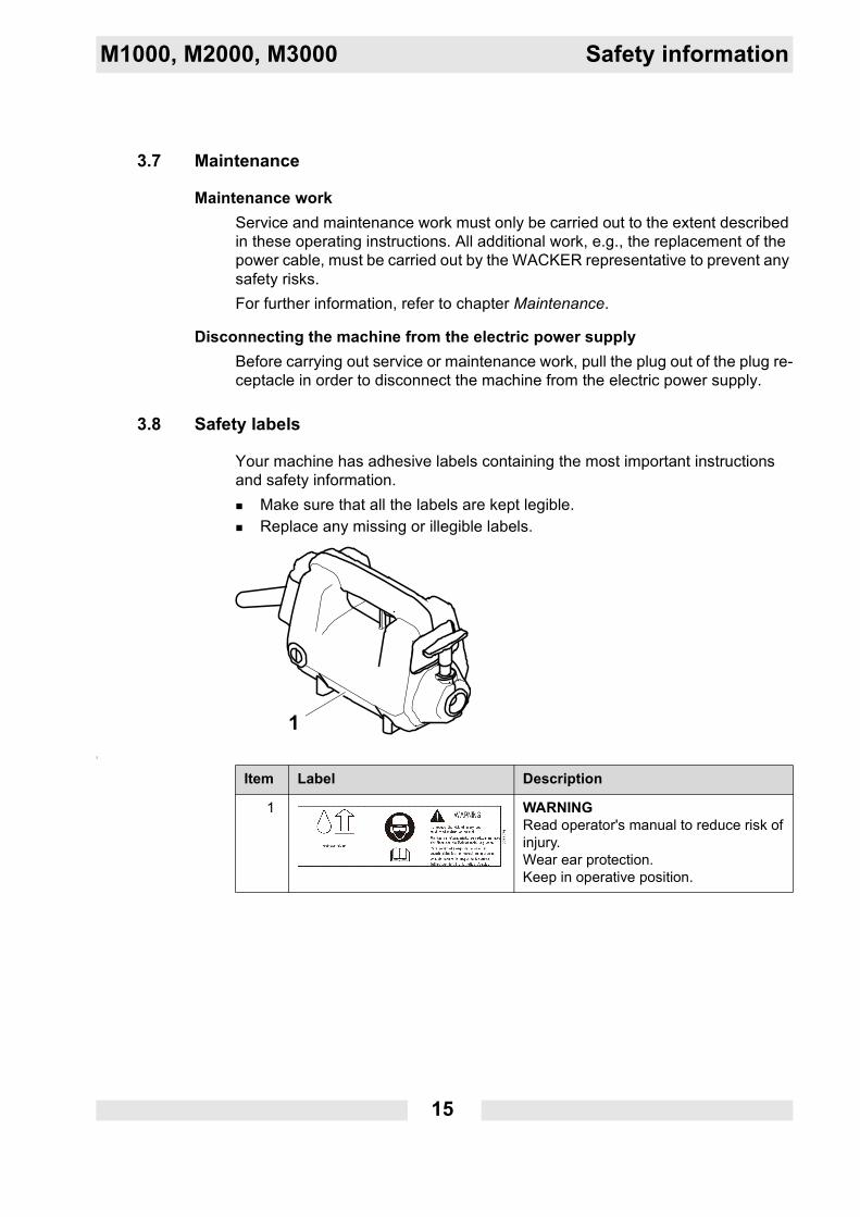
3.8 Safety labels
Your machine has adhesive labels containing the most important instructions and safety information.
Make sure that all the labels are kept legible.Replace any missing or illegible labels.
2
Item Label Description
1 WARNINGRead operator's manual to reduce risk of injury.Wear ear protection.Keep in operative position.
16
Scope of delivery M1000, M2000, M3000
4 Scope of delivery
Individual components of the machine must be ordered separately.The total scope of delivery includes:
Drive.Flexible shaft.Vibrator head.Operator's manual.Parts book.General safety instructions.
M1000, M2000, M3000 Description
17
5 Description
5.1 Application
The machine is designed to compact fresh concrete in formworks and on even surfaces.The vibrator head has to be immersed in the fresh concrete.
5.2 Functionality
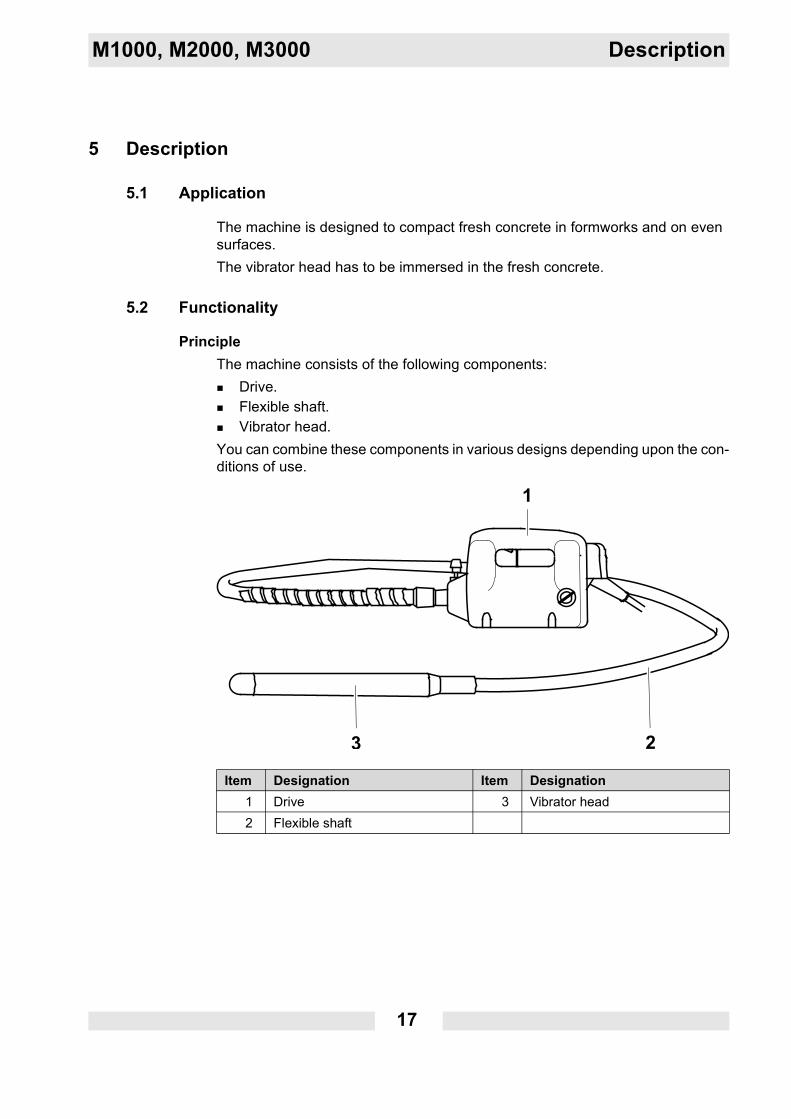
PrincipleThe machine consists of the following components:
Drive.Flexible shaft.Vibrator head.
You can combine these components in various designs depending upon the con-ditions of use.
Item Designation Item Designation1 Drive 3 Vibrator head2 Flexible shaft
18
Description M1000, M2000, M3000
By means of the flexible shaft, the drive drives the vibrator head, which gener-ates high-frequency vibrations. These vibrations will cause the vibrator head to execute precessions.Concrete is deaerated and compressed in the effective range of the vibrator head when the vibrator head is immersed into the fresh concrete.The fresh concrete is simultaneously cooling the vibrator head.
Note: The concrete is being compressed for as long as bubbles of air arise.
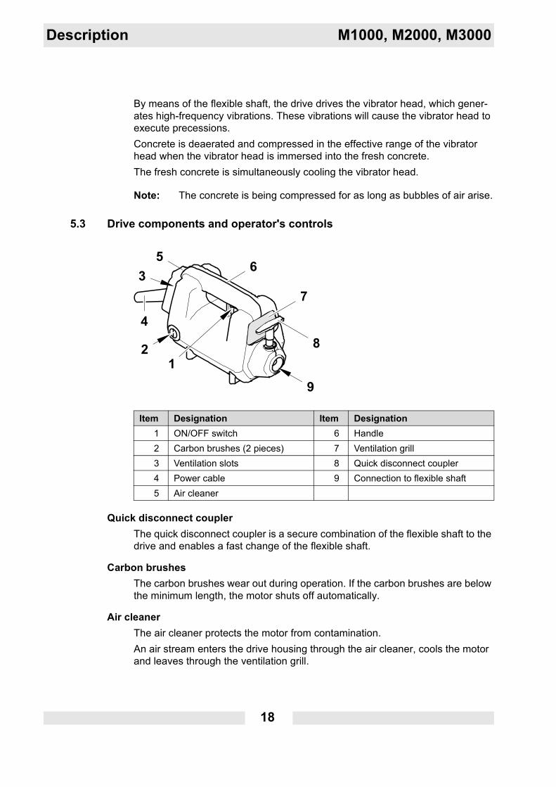
5.3 Drive components and operator's controls
Quick disconnect couplerThe quick disconnect coupler is a secure combination of the flexible shaft to the drive and enables a fast change of the flexible shaft.
Carbon brushesThe carbon brushes wear out during operation. If the carbon brushes are below the minimum length, the motor shuts off automatically.
Air cleanerThe air cleaner protects the motor from contamination.An air stream enters the drive housing through the air cleaner, cools the motor and leaves through the ventilation grill.
Item Designation Item Designation1 ON/OFF switch 6 Handle2 Carbon brushes (2 pieces) 7 Ventilation grill3 Ventilation slots 8 Quick disconnect coupler4 Power cable 9 Connection to flexible shaft5 Air cleaner
M1000, M2000, M3000 Description
19
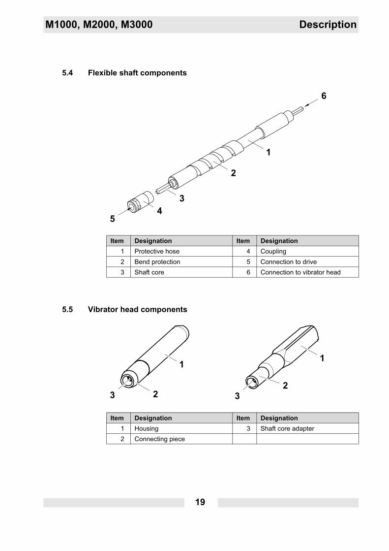
5.4 Flexible shaft components
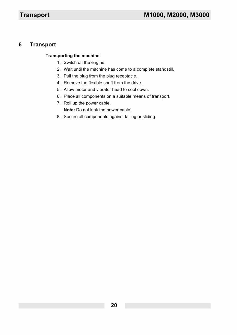
5.5 Vibrator head components
Item Designation Item Designation1 Protective hose 4 Coupling2 Bend protection 5 Connection to drive3 Shaft core 6 Connection to vibrator head
Item Designation Item Designation1 Housing 3 Shaft core adapter2 Connecting piece
20
Transport M1000, M2000, M3000
6 Transport
Transporting the machine1. Switch off the engine.2. Wait until the machine has come to a complete standstill.3. Pull the plug from the plug receptacle.4. Remove the flexible shaft from the drive.5. Allow motor and vibrator head to cool down.6. Place all components on a suitable means of transport.7. Roll up the power cable.
Note: Do not kink the power cable!8. Secure all components against falling or sliding.
M1000, M2000, M3000 Operation
21
7 Operation
7.1 Prior to starting the machine
After unpacking, the machine is ready for operation.
PlugThe machine comes with a country-specific plug as a standard equipment.
Note on the version without mains plug (non-EU countries)
Carrying out checksCheck if mains or power distribution on the construction site have the correct operating voltage (see nameplate of the machine or chapter Technical Data).Check if mains or power distribution on the constructions site are protected in accordance with current standards and regulations.
WARNINGImproper handling can result in injury or serious material damage.
Read and follow all safety instructions of this operator's manual, see chapter Safety information.
WARNINGLeakage current due to permeating moisture. Injuries from electrocution.
In moist environment keep or set the machine in operative position.Use extension cable of IPx4 design, so that the plug/coupling connection is protected from spraying water.
DANGERImproper assembly of plug.Danger of electrocution.
Only a qualified electrician is permitted to assemble the plug and perform a subsequent safety check according to the directives in effect.Observe the assembly instructions.
22
Operation M1000, M2000, M3000
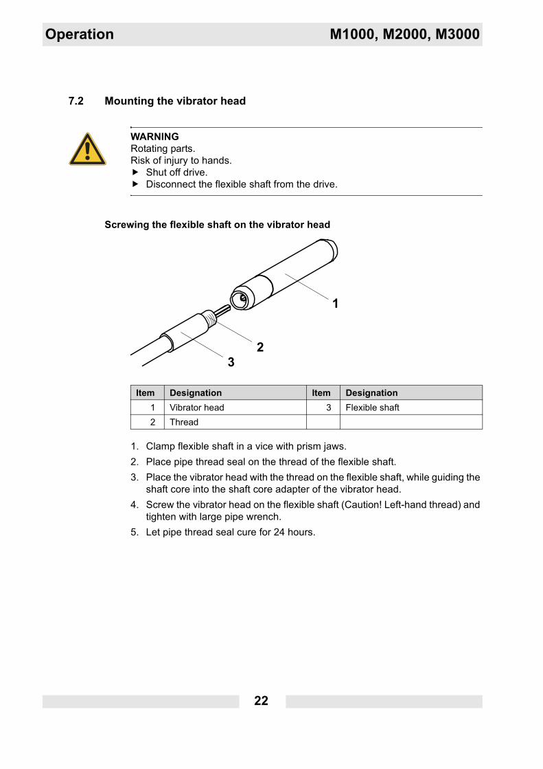
7.2 Mounting the vibrator head
Screwing the flexible shaft on the vibrator head
1. Clamp flexible shaft in a vice with prism jaws.2. Place pipe thread seal on the thread of the flexible shaft.3. Place the vibrator head with the thread on the flexible shaft, while guiding the
shaft core into the shaft core adapter of the vibrator head.4. Screw the vibrator head on the flexible shaft (Caution! Left-hand thread) and
tighten with large pipe wrench.5. Let pipe thread seal cure for 24 hours.
WARNINGRotating parts.Risk of injury to hands.
Shut off drive.Disconnect the flexible shaft from the drive.
Item Designation Item Designation1 Vibrator head 3 Flexible shaft2 Thread
M1000, M2000, M3000 Operation
23
Coupling the flexible shaft to the drive
1. Set drive upright on the floor. Drive must be shut off.
2. Lift quick disconnect coupler.3. Stick the flexible shaft coupling in the drive coupling, while guiding the shaft
core in the shaft core adapter of the drive.4. Guide the flexible shaft coupling until it stops.5. Release the quick disconnect coupler.6. Turn the flexible shaft until the quick disconnect coupler engages.7. Control whether the quick disconnect coupler is completely engaged by pull-
ing on the flexible shaft.
Note: If the flexible shaft core is new, the drive must run approx. 5 minutes with the flexible shaft connected (if necessary with the vibrator head as well).
Item Designation1 Flexible shaft2 Coupling3 Quick disconnect coupler
24
Operation M1000, M2000, M3000
7.3 Starting up
Connecting the machine to the power supply
1. Turn off ON/OFF switch.Note: When the ON/OFF switch is pressed, the machine starts to run imme-diately at the connection. The machine can strike out and may injure persons or be damaged.
2. If required, connect a permitted extension cable to the power cable of the ma-chine.Note: See chapter Technical data for the permitted lengths and cross-section areas of extension cables.
3. Insert the plug into the plug receptacle.
NOTICEElectrical voltage.Incorrect voltage can cause damage on the machine.
Check if the voltage of the current source corresponds with the information of the machine, see chapter Technical Data.
WARNINGElectrical voltage.Injuries from electrocution.
Check power cable and extension cable for signs of damage.Only use extension cables for which grounded conductors are connected to the plug and the coupling (only for machines of class rating I).
M1000, M2000, M3000 Operation
25
Switching on the machine
1. Lift vibrator head from floor with protective hose, to prevent damage to the machine or foundation.
2. Switch on the machine via the ON/OFF switch.
Compacting fresh concrete1. Quickly immerse the vibrator head in the fresh concrete, hold it for several
seconds and slowly pull it out again.2. Immerse the vibrator head in all areas of the formwork and compact the fresh
concrete.
Note:Compact especially intensively in corner areas and the formwork because of the high reinforcement. Make sure that the vibrator head does not touch the reinforcement. Damages can occur both on the vibrator head and also on the concrete, if it is already in the curing process.The holding time of the vibrator head in the concrete depends on the diame-ter of the vibrator head, the consistency of the concrete and the layer thick-ness.Indications that the concrete is sufficiently compacted:
The concrete no longer sets.Air bubbles no longer or rarely rise.The sound of the vibrator head is not changing anymore.
Item Designation1 ON/OFF switch
26
Operation M1000, M2000, M3000
7.4 Decomissioning
Switching off the machine
1. Slowly remove the machine from the fresh concrete; hold the vibrator head in the air.
2. Switch off the machine via the ON/OFF switch.3. Wait until the machine has come to a complete standstill.4. Put down the machine slowly.
Note: Do not kink the protective hose and power cable!5. Pull the plug from the plug receptacle.
Disconnecting the flexible shaft from the drive
1. Lift quick disconnect coupler.2. Remove the flexible shaft coupling from the drive coupling.3. Release the quick disconnect coupler.
NOTICEThe vibrator head moves if it is turned on and not immersed in the fresh con-crete.Danger of injury or danger of damage to property by uncontrolled vibrator head.
Switch the machine off before you put it down.
NOTICEThe vibrator head heats up if it is turned on and not immersed in the fresh con-crete.Hot surface can cause burns.Damage to the machine with excessive wear.
Do not operate the machine with the internal vibrator not immersed in the fresh concrete.
NOTICEThe coupling of the flexible shaft heats up during operation.Hot surface can cause burns.
Allow the coupling of the flexible shaft to cool before touching it.
M1000, M2000, M3000 Operation
27
Cleaning the machineClean the machine after each use.1. Clean the vibrator head and protective hose with water.
Note: You can remove concrete residuals by immersing the running machine into gravel.
2. Wipe the drive with a damp and clean cloth.3. Clean the ventilation grill with a suitable tool.
28
Maintenance M1000, M2000, M3000
8 Maintenance
WARNINGImproper handling can result in injury or serious material damage.
Read and follow all safety instructions of this operator's manual, see chapter Safety information.
WARNINGElectrical voltage.Injuries from electrocution.
Remove the plug from the plug receptacle before all work on the machine.
M1000, M2000, M3000 Maintenance
29
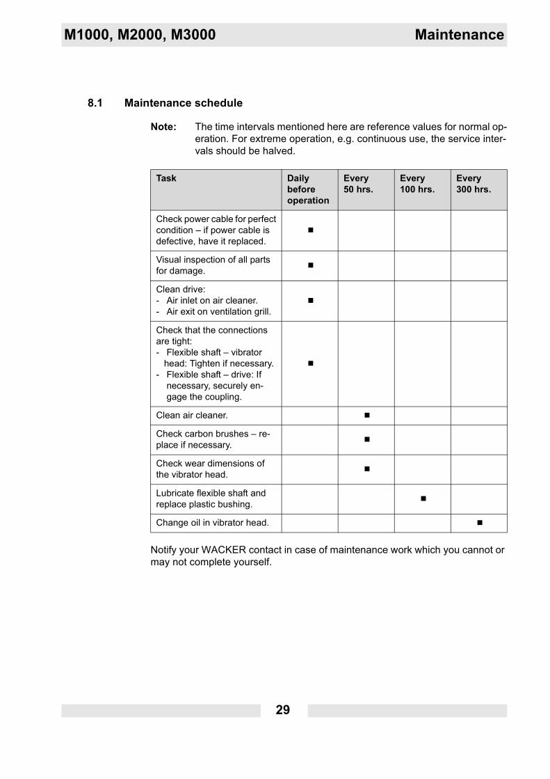
8.1 Maintenance schedule
Note: The time intervals mentioned here are reference values for normal op-eration. For extreme operation, e.g. continuous use, the service inter-vals should be halved.
Notify your WACKER contact in case of maintenance work which you cannot or may not complete yourself.
Task Daily before operation
Every 50 hrs.
Every 100 hrs.
Every 300 hrs.
Check power cable for perfect condition – if power cable is defective, have it replaced.
Visual inspection of all parts for damage.
Clean drive:- Air inlet on air cleaner.- Air exit on ventilation grill.
Check that the connections are tight:- Flexible shaft – vibrator
head: Tighten if necessary.- Flexible shaft – drive: If
necessary, securely en-gage the coupling.
Clean air cleaner.
Check carbon brushes – re-place if necessary.
Check wear dimensions of the vibrator head.
Lubricate flexible shaft and replace plastic bushing.
Change oil in vibrator head.
30
Maintenance M1000, M2000, M3000
8.2 Maintenance work
Work in the workshopPerform maintenance work in a workshop on a workbench. This has the following benefits:
Protection of the machine of contamination on the construction site.A level and clean work surface makes work easier.There is a better overview over small parts and they are not lost as easily.
8.2.1 Visual inspection
Checking the machine
Check all machine components for damage or cracks.
WARNINGA damaged machine part or power cable can result in personal injury caused by electric current.
Do not operate a damaged machine.Have a damaged machine repaired immediately.
M1000, M2000, M3000 Maintenance
31
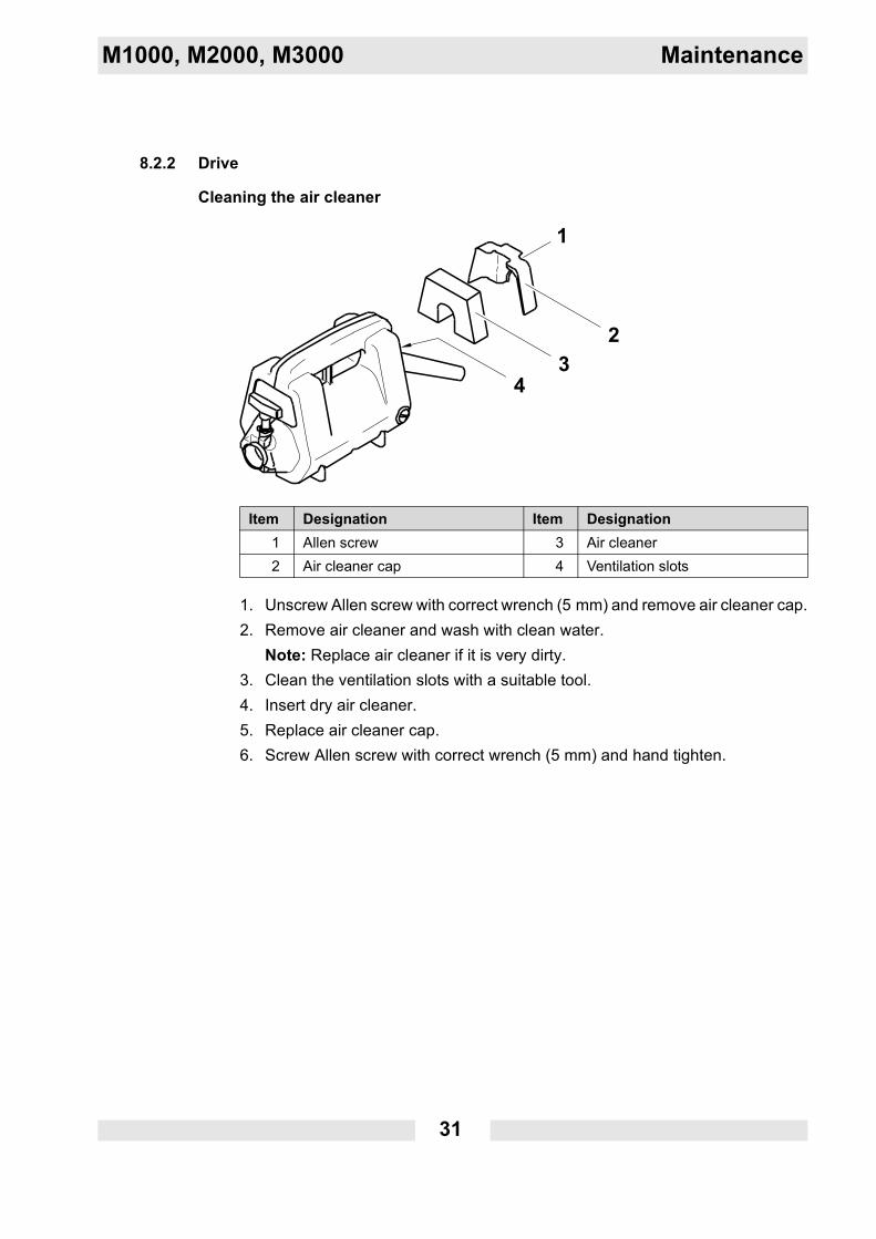
8.2.2 Drive
Cleaning the air cleaner
1. Unscrew Allen screw with correct wrench (5 mm) and remove air cleaner cap.2. Remove air cleaner and wash with clean water.
Note: Replace air cleaner if it is very dirty.3. Clean the ventilation slots with a suitable tool.4. Insert dry air cleaner.5. Replace air cleaner cap.6. Screw Allen screw with correct wrench (5 mm) and hand tighten.
Item Designation Item Designation1 Allen screw 3 Air cleaner2 Air cleaner cap 4 Ventilation slots
32
Maintenance M1000, M2000, M3000
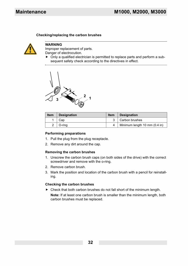
Checking/replacing the carbon brushes
Performing preparations1. Pull the plug from the plug receptacle.2. Remove any dirt around the cap.
Removing the carbon brushes1. Unscrew the carbon brush caps (on both sides of the drive) with the correct
screwdriver and remove with the o-ring.2. Remove carbon brush.3. Mark the position and location of the carbon brush with a pencil for reinstall-
ing.
Checking the carbon brushesCheck that both carbon brushes do not fall short of the minimum length.Note: If at least one carbon brush is smaller than the minimum length, both carbon brushes must be replaced.
WARNINGImproper replacement of parts.Danger of electrocution.
Only a qualified electrician is permitted to replace parts and perform a sub-sequent safety check according to the directives in effect.
Item Designation Item Designation1 Cap 3 Carbon brushes2 O-ring 4 Minimum length 10 mm (0.4 in)
M1000, M2000, M3000 Maintenance
33
Inserting the carbon brushes1. Install carbon brush (on both sides of drive).
Pay attention to the original position and location of used carbon brushes, to avoid damage and sparking on the collector.
2. Screw on cap with o-ring and tighten with a screwdriver hand tight.
Note: If you have installed new carbon brushes, the drive must be run for ap-prox. 5 minutes without the flexible shaft attached.
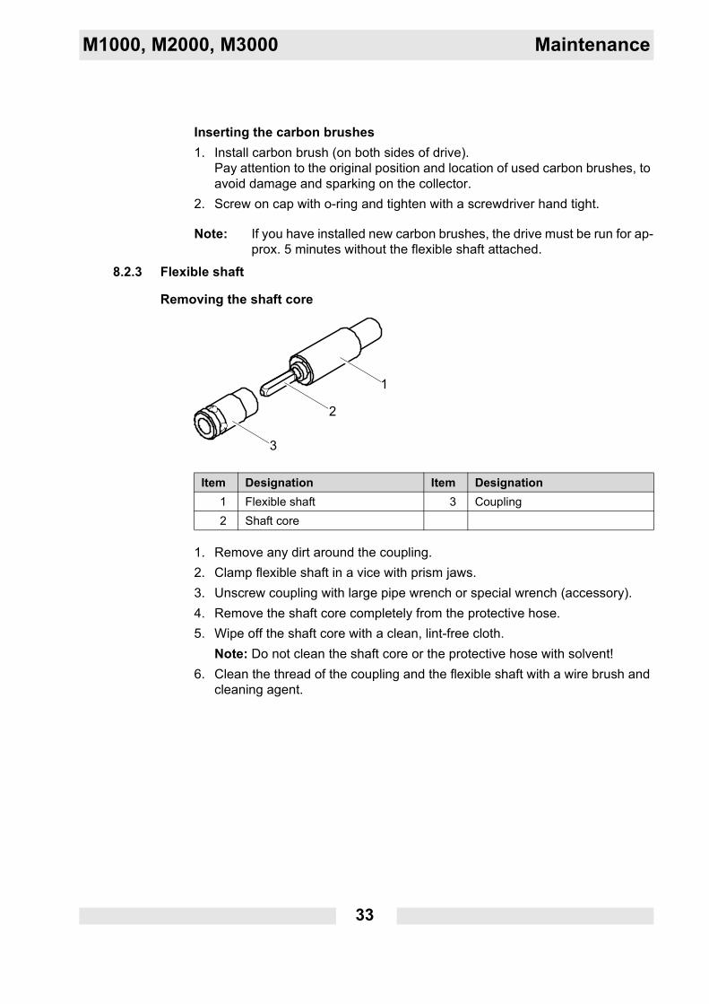
8.2.3 Flexible shaft
Removing the shaft core
1. Remove any dirt around the coupling.2. Clamp flexible shaft in a vice with prism jaws.3. Unscrew coupling with large pipe wrench or special wrench (accessory).4. Remove the shaft core completely from the protective hose.5. Wipe off the shaft core with a clean, lint-free cloth.
Note: Do not clean the shaft core or the protective hose with solvent!6. Clean the thread of the coupling and the flexible shaft with a wire brush and
cleaning agent.
Item Designation Item Designation1 Flexible shaft 3 Coupling2 Shaft core
34
Maintenance M1000, M2000, M3000
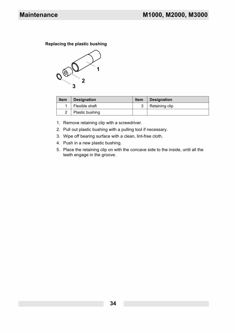
Replacing the plastic bushing
1. Remove retaining clip with a screwdriver.2. Pull out plastic bushing with a pulling tool if necessary.3. Wipe off bearing surface with a clean, lint-free cloth.4. Push in a new plastic bushing.5. Place the retaining clip on with the concave side to the inside, until all the
teeth engage in the groove.
Item Designation Item Designation1 Flexible shaft 3 Retaining clip2 Plastic bushing
M1000, M2000, M3000 Maintenance
35
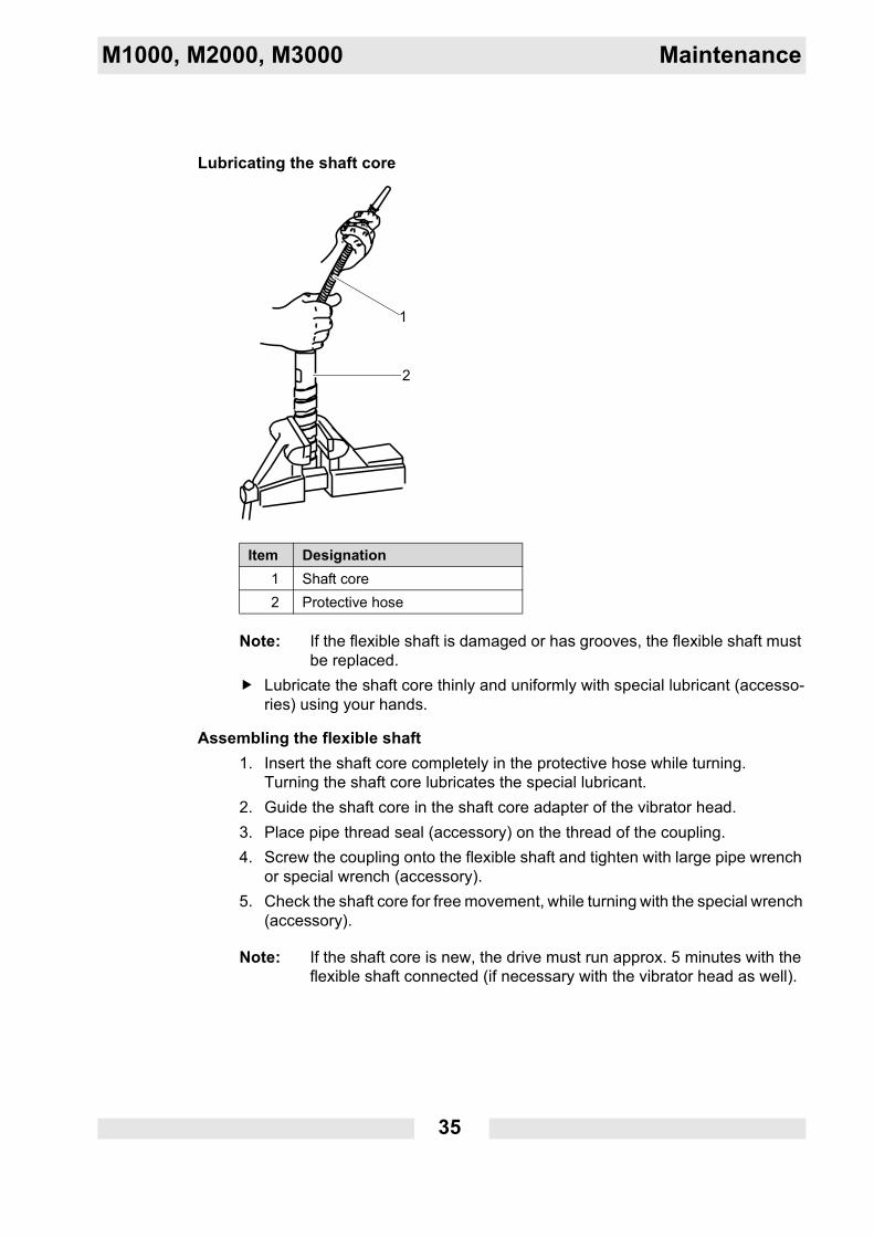
Lubricating the shaft core
Note: If the flexible shaft is damaged or has grooves, the flexible shaft must be replaced.
Lubricate the shaft core thinly and uniformly with special lubricant (accesso-ries) using your hands.
Assembling the flexible shaft1. Insert the shaft core completely in the protective hose while turning.
Turning the shaft core lubricates the special lubricant.2. Guide the shaft core in the shaft core adapter of the vibrator head.3. Place pipe thread seal (accessory) on the thread of the coupling.4. Screw the coupling onto the flexible shaft and tighten with large pipe wrench
or special wrench (accessory).5. Check the shaft core for free movement, while turning with the special wrench
(accessory).
Note: If the shaft core is new, the drive must run approx. 5 minutes with the flexible shaft connected (if necessary with the vibrator head as well).
Item Designation1 Shaft core2 Protective hose
36
Maintenance M1000, M2000, M3000
8.2.4 Vibrator head
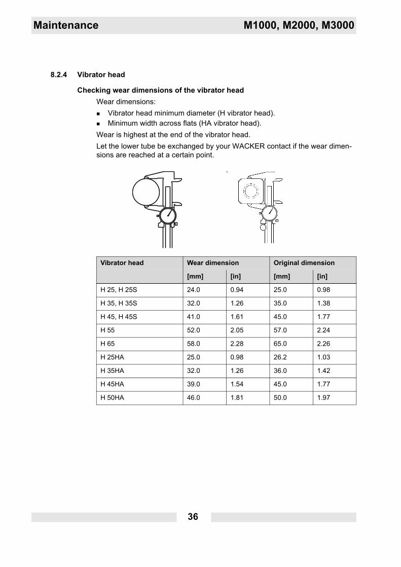
Checking wear dimensions of the vibrator headWear dimensions:
Vibrator head minimum diameter (H vibrator head).Minimum width across flats (HA vibrator head).
Wear is highest at the end of the vibrator head.Let the lower tube be exchanged by your WACKER contact if the wear dimen-sions are reached at a certain point.
Vibrator head Wear dimension Original dimension
[mm] [in] [mm] [in]
H 25, H 25S 24.0 0.94 25.0 0.98
H 35, H 35S 32.0 1.26 35.0 1.38
H 45, H 45S 41.0 1.61 45.0 1.77
H 55 52.0 2.05 57.0 2.24
H 65 58.0 2.28 65.0 2.26
H 25HA 25.0 0.98 26.2 1.03
H 35HA 32.0 1.26 36.0 1.42
H 45HA 39.0 1.54 45.0 1.77
H 50HA 46.0 1.81 50.0 1.97
M1000, M2000, M3000 Maintenance
37
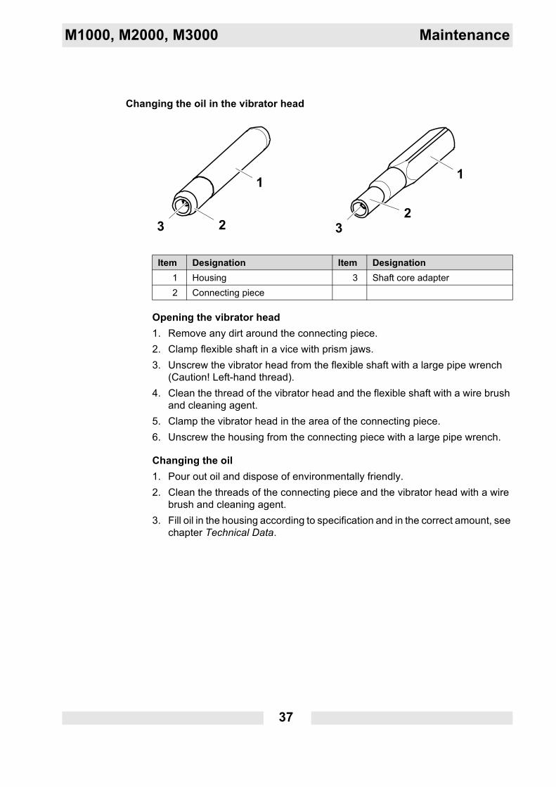
Changing the oil in the vibrator head
Opening the vibrator head1. Remove any dirt around the connecting piece.2. Clamp flexible shaft in a vice with prism jaws.3. Unscrew the vibrator head from the flexible shaft with a large pipe wrench
(Caution! Left-hand thread).4. Clean the thread of the vibrator head and the flexible shaft with a wire brush
and cleaning agent.5. Clamp the vibrator head in the area of the connecting piece.6. Unscrew the housing from the connecting piece with a large pipe wrench.
Changing the oil1. Pour out oil and dispose of environmentally friendly.2. Clean the threads of the connecting piece and the vibrator head with a wire
brush and cleaning agent.3. Fill oil in the housing according to specification and in the correct amount, see
chapter Technical Data.
Item Designation Item Designation1 Housing 3 Shaft core adapter2 Connecting piece
38
Maintenance M1000, M2000, M3000
Assembling the vibrator head1. Place pipe thread seal on the thread of the housing.2. Screw the housing on the connecting piece and tighten with a large pipe
wrench.3. Place pipe thread seal on the thread of the flexible shaft.4. Place the vibrator head with the thread on the flexible shaft, while guiding the
shaft core into the shaft core adapter of the vibrator head.5. Screw the vibrator head on the flexible shaft (Caution! Left-hand thread) and
tighten with large pipe wrench.6. Let pipe thread seal cure for 24 hours.
M1000, M2000, M3000 Troubleshooting
39
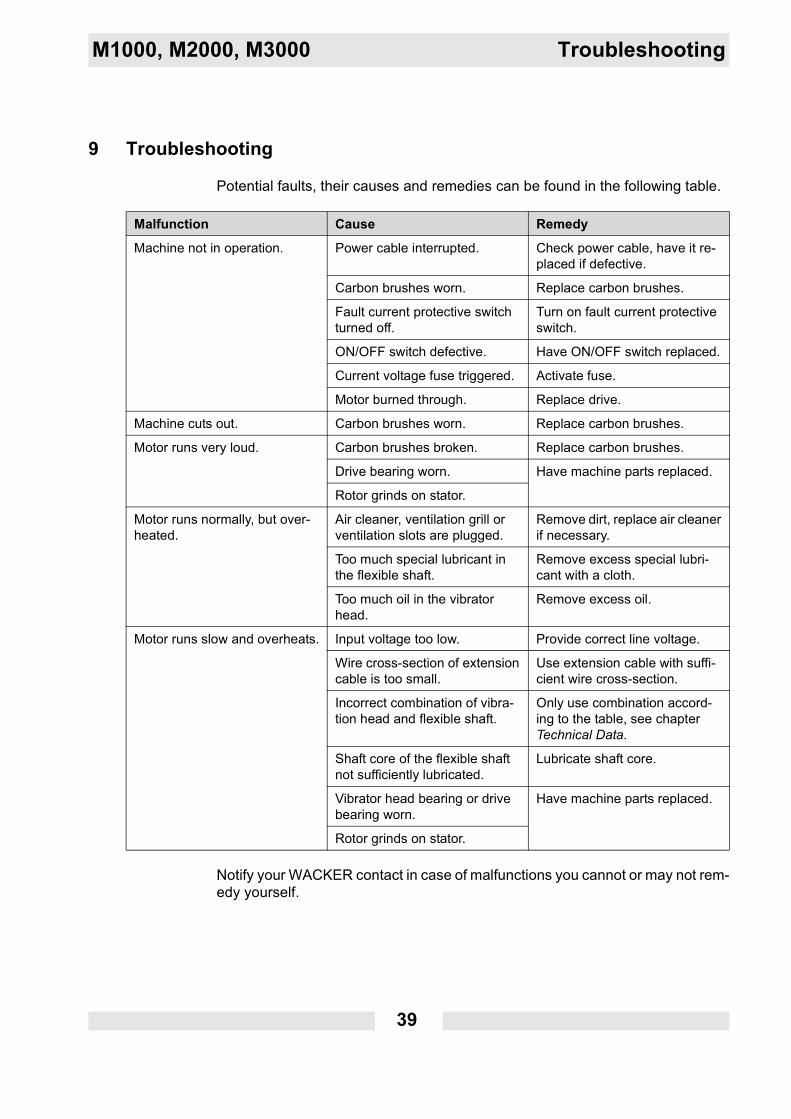
9 Troubleshooting
Potential faults, their causes and remedies can be found in the following table.
Notify your WACKER contact in case of malfunctions you cannot or may not rem-edy yourself.
Malfunction Cause Remedy
Machine not in operation. Power cable interrupted. Check power cable, have it re-placed if defective.
Carbon brushes worn. Replace carbon brushes.
Fault current protective switch turned off.
Turn on fault current protective switch.
ON/OFF switch defective. Have ON/OFF switch replaced.
Current voltage fuse triggered. Activate fuse.
Motor burned through. Replace drive.
Machine cuts out. Carbon brushes worn. Replace carbon brushes.
Motor runs very loud. Carbon brushes broken. Replace carbon brushes.
Drive bearing worn. Have machine parts replaced.
Rotor grinds on stator.
Motor runs normally, but over-heated.
Air cleaner, ventilation grill or ventilation slots are plugged.
Remove dirt, replace air cleaner if necessary.
Too much special lubricant in the flexible shaft.
Remove excess special lubri-cant with a cloth.
Too much oil in the vibrator head.
Remove excess oil.
Motor runs slow and overheats. Input voltage too low. Provide correct line voltage.
Wire cross-section of extension cable is too small.
Use extension cable with suffi-cient wire cross-section.
Incorrect combination of vibra-tion head and flexible shaft.
Only use combination accord-ing to the table, see chapter Technical Data.
Shaft core of the flexible shaft not sufficiently lubricated.
Lubricate shaft core.
Vibrator head bearing or drive bearing worn.
Have machine parts replaced.
Rotor grinds on stator.
40
Disposal M1000, M2000, M3000
10 Disposal
10.1 Disposal of the machine
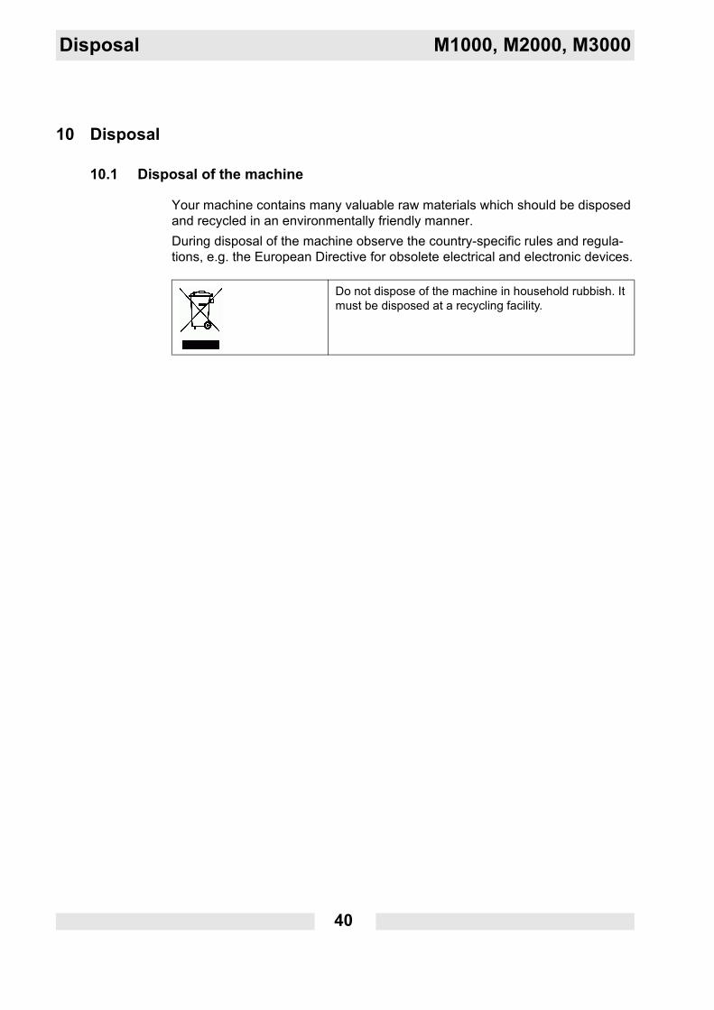
Your machine contains many valuable raw materials which should be disposed and recycled in an environmentally friendly manner. During disposal of the machine observe the country-specific rules and regula-tions, e.g. the European Directive for obsolete electrical and electronic devices.
Do not dispose of the machine in household rubbish. It must be disposed at a recycling facility.
M1000, M2000, M3000 Accessories
41
11 Accessories
There is a wide range of accessories available for the machine.For more information on the individual accessories, visit the following website: www.wackergroup.com.
11.1 Special wrench for flexible shaft
The flexible shaft coupling can be removed easier with the special wrench.
11.2 Pipe thread seal
The pipe thread seal is needed for sealing the thread connection between the vi-brator head and the flexible shaft, as well as between coupling and flexible shaft.
11.3 Special lubricant for flexible shafts
The WACKER special lubricant is needed for lubricating flexible shaft cores in the flexible shafts.
11.4 SS-adapter
The SS-adapter is used to connect two S-flexible shafts.
Various lengths of flexible shafts is found in the Technical Data chapter.
11.5 Carrying belt
You can carry the drive with the carrying belt, if you must often change position.
NOTICEMotor overload.Flexible shafts which are too long can overload the motor.
Keep a total length of 9 m (29.6 ft).
42
Technical data M1000, M2000, M3000
12 Technical data
12.1 Drive
Note: All drives are double insulated. In addition, some models have a grounded conductor connection.
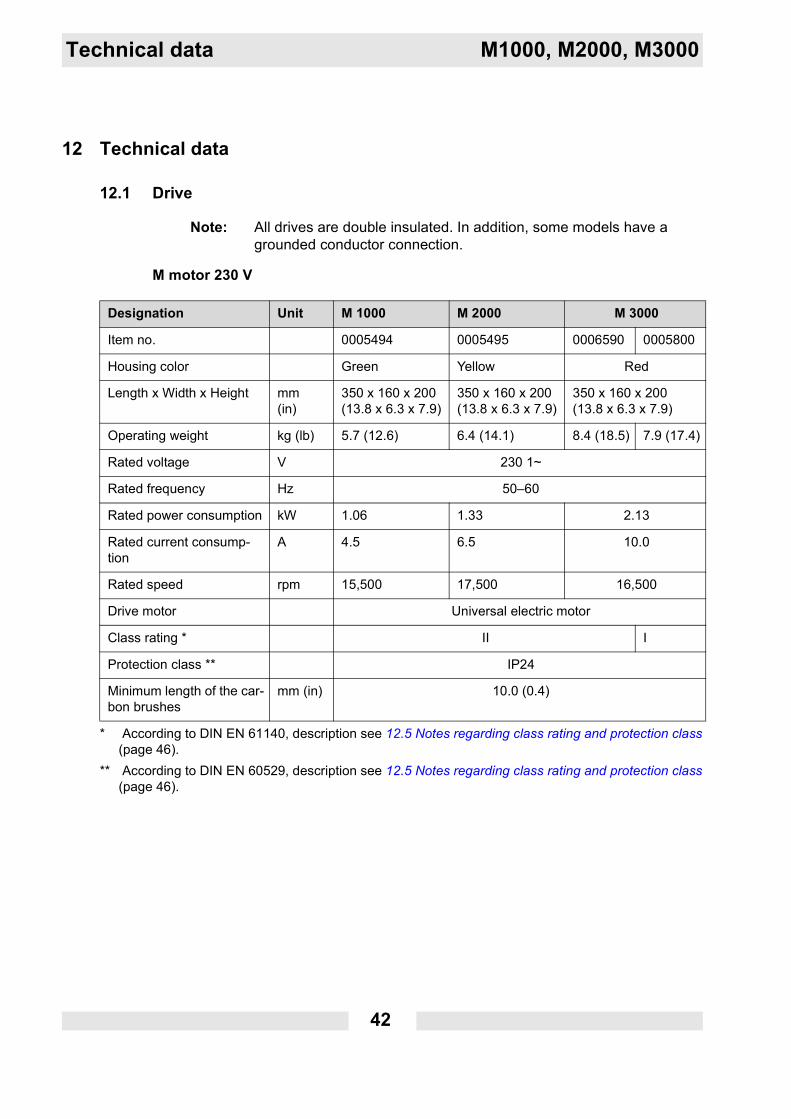
M motor 230 V
Designation Unit M 1000 M 2000 M 3000
Item no. 0005494 0005495 0006590 0005800
Housing color Green Yellow Red
Length x Width x Height mm(in)
350 x 160 x 200(13.8 x 6.3 x 7.9)
350 x 160 x 200(13.8 x 6.3 x 7.9)
350 x 160 x 200(13.8 x 6.3 x 7.9)
Operating weight kg (lb) 5.7 (12.6) 6.4 (14.1) 8.4 (18.5) 7.9 (17.4)
Rated voltage V 230 1~
Rated frequency Hz 50–60
Rated power consumption kW 1.06 1.33 2.13
Rated current consump-tion
A 4.5 6.5 10.0
Rated speed rpm 15,500 17,500 16,500
Drive motor Universal electric motor
Class rating *
* According to DIN EN 61140, description see 12.5 Notes regarding class rating and protection class (page 46).
II I
Protection class **
** According to DIN EN 60529, description see 12.5 Notes regarding class rating and protection class (page 46).
IP24
Minimum length of the car-bon brushes
mm (in) 10.0 (0.4)
M1000, M2000, M3000 Technical data
43
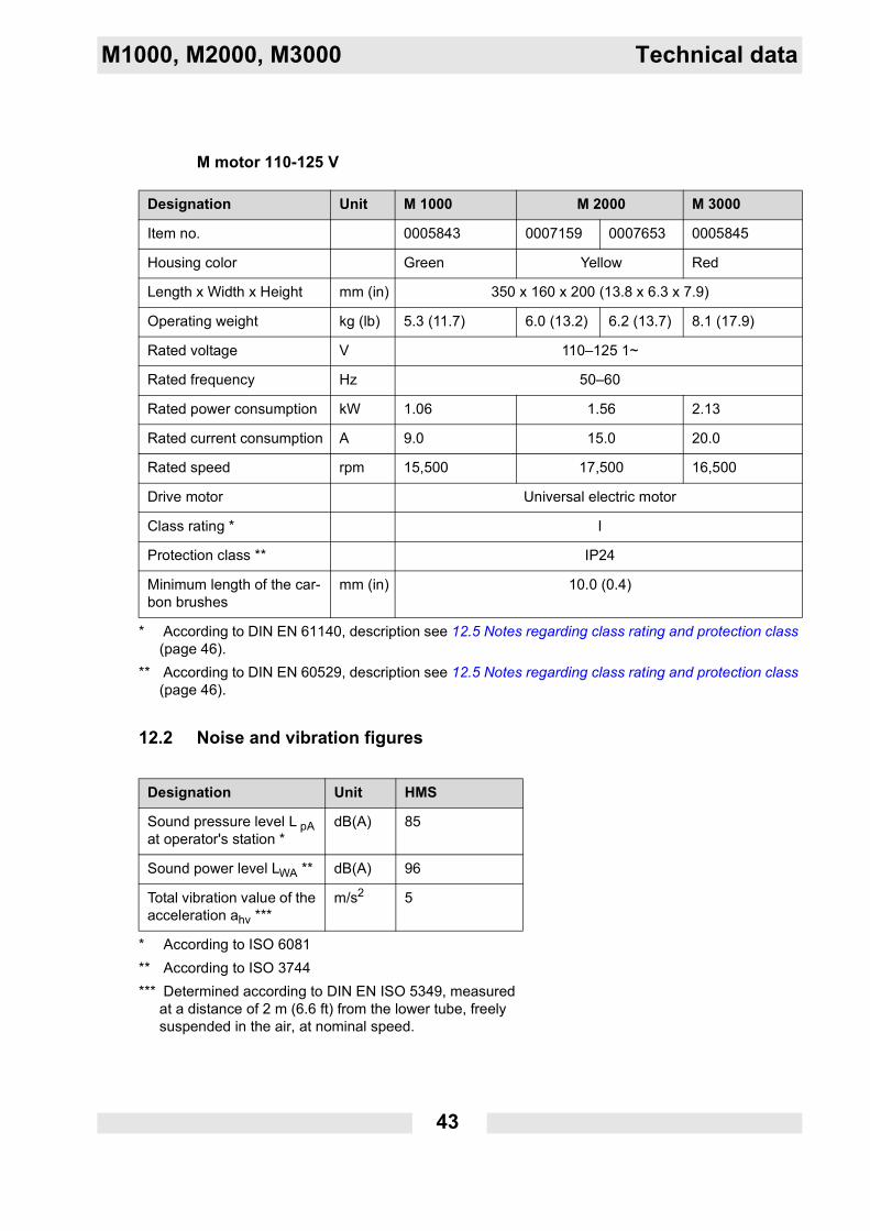
M motor 110-125 V
12.2 Noise and vibration figures
Designation Unit M 1000 M 2000 M 3000
Item no. 0005843 0007159 0007653 0005845
Housing color Green Yellow Red
Length x Width x Height mm (in) 350 x 160 x 200 (13.8 x 6.3 x 7.9)
Operating weight kg (lb) 5.3 (11.7) 6.0 (13.2) 6.2 (13.7) 8.1 (17.9)
Rated voltage V 110–125 1~
Rated frequency Hz 50–60
Rated power consumption kW 1.06 1.56 2.13
Rated current consumption A 9.0 15.0 20.0
Rated speed rpm 15,500 17,500 16,500
Drive motor Universal electric motor
Class rating *
* According to DIN EN 61140, description see 12.5 Notes regarding class rating and protection class (page 46).
I
Protection class **
** According to DIN EN 60529, description see 12.5 Notes regarding class rating and protection class (page 46).
IP24
Minimum length of the car-bon brushes
mm (in) 10.0 (0.4)
Designation Unit HMS
Sound pressure level L pA at operator's station *
* According to ISO 6081
dB(A) 85
Sound power level LWA **
** According to ISO 3744
dB(A) 96
Total vibration value of the acceleration ahv ***
*** Determined according to DIN EN ISO 5349, measured at a distance of 2 m (6.6 ft) from the lower tube, freely suspended in the air, at nominal speed.
m/s2 5
44
Technical data M1000, M2000, M3000
12.3 Flexible shafts
S-flexible shafts
E-flexible shafts
Designation Unit SM0-S SM1-S SM2-S SM3-S
Length m (ft) 0.5 (1.6) 1.0 (3.3) 2.0 (6.6) 3.0 (9.8)
Weight kg (lb) 1.3 (2.9) 2.7 (5.9) 4.3 (9.5) 5.9 (13.0)
Designation Unit SM4-S SM5-S SM7-S SM9-S
Length m (ft) 4.0 (13.1) 5.0 (16.4) 7.0 (23.0) 9.0 (29.5)
Weight kg (lb) 7.1 (15.7) 9.3 (20.5) 12.9 (28.4) 15.1 (33.3)
Designation Unit SM1-E SM2-E SM4-E
Length m (ft) 1.0 (1.6) 2.0 (6.6) 4.0 (13.1)
Weight kg (lb) 1.5 (3.3) 2.5 (5.5) 4.3 (9.8)
M1000, M2000, M3000 Technical data
45
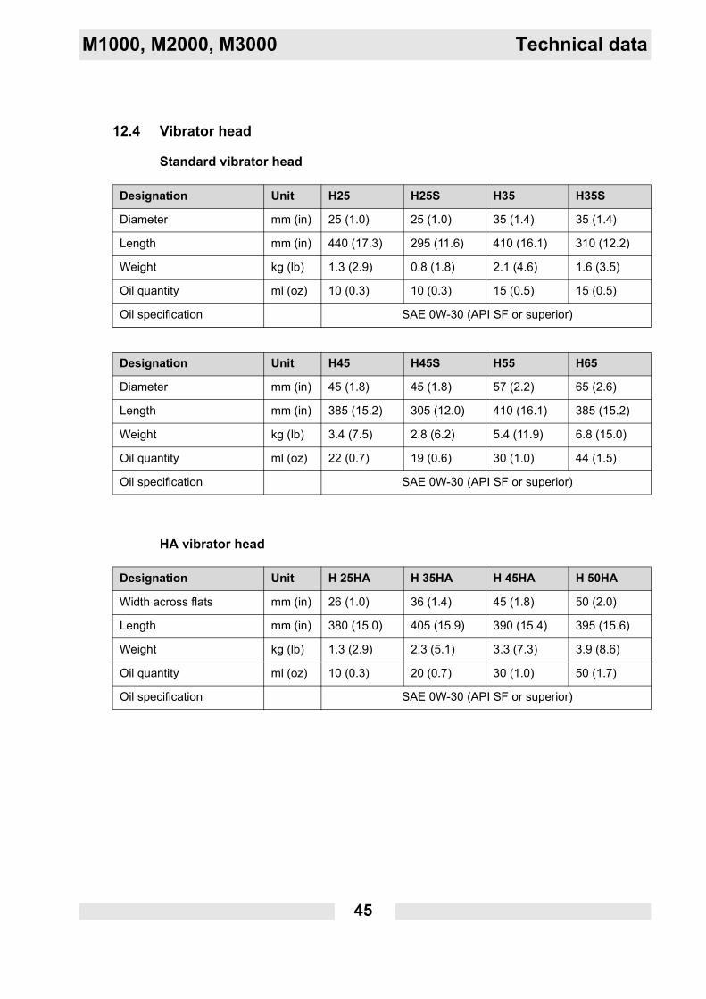
12.4 Vibrator head
Standard vibrator head
HA vibrator head
Designation Unit H25 H25S H35 H35S
Diameter mm (in) 25 (1.0) 25 (1.0) 35 (1.4) 35 (1.4)
Length mm (in) 440 (17.3) 295 (11.6) 410 (16.1) 310 (12.2)
Weight kg (lb) 1.3 (2.9) 0.8 (1.8) 2.1 (4.6) 1.6 (3.5)
Oil quantity ml (oz) 10 (0.3) 10 (0.3) 15 (0.5) 15 (0.5)
Oil specification SAE 0W-30 (API SF or superior)
Designation Unit H45 H45S H55 H65
Diameter mm (in) 45 (1.8) 45 (1.8) 57 (2.2) 65 (2.6)
Length mm (in) 385 (15.2) 305 (12.0) 410 (16.1) 385 (15.2)
Weight kg (lb) 3.4 (7.5) 2.8 (6.2) 5.4 (11.9) 6.8 (15.0)
Oil quantity ml (oz) 22 (0.7) 19 (0.6) 30 (1.0) 44 (1.5)
Oil specification SAE 0W-30 (API SF or superior)
Designation Unit H 25HA H 35HA H 45HA H 50HA
Width across flats mm (in) 26 (1.0) 36 (1.4) 45 (1.8) 50 (2.0)
Length mm (in) 380 (15.0) 405 (15.9) 390 (15.4) 395 (15.6)
Weight kg (lb) 1.3 (2.9) 2.3 (5.1) 3.3 (7.3) 3.9 (8.6)
Oil quantity ml (oz) 10 (0.3) 20 (0.7) 30 (1.0) 50 (1.7)
Oil specification SAE 0W-30 (API SF or superior)
46
Technical data M1000, M2000, M3000
12.5 Notes regarding class rating and protection class
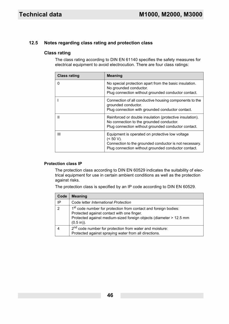
Class ratingThe class rating according to DIN EN 61140 specifies the safety measures for electrical equipment to avoid electrocution. There are four class ratings:
Protection class IPThe protection class according to DIN EN 60529 indicates the suitability of elec-trical equipment for use in certain ambient conditions as well as the protection against risks.The protection class is specified by an IP code according to DIN EN 60529.
Class rating Meaning
0 No special protection apart from the basic insulation.No grounded conductor.Plug connection without grounded conductor contact.
I Connection of all conductive housing components to the grounded conductor. Plug connection with grounded conductor contact.
II Reinforced or double insulation (protective insulation).No connection to the grounded conductor. Plug connection without grounded conductor contact.
III Equipment is operated on protective low voltage (< 50 V).Connection to the grounded conductor is not necessary. Plug connection without grounded conductor contact.
Code MeaningIP Code letter International Protection2 1st code number for protection from contact and foreign bodies:
Protected against contact with one finger.Protected against medium-sized foreign objects (diameter > 12.5 mm (0.5 in)).
4 2nd code number for protection from water and moisture:Protected against spraying water from all directions.
M1000, M2000, M3000 Technical data
47
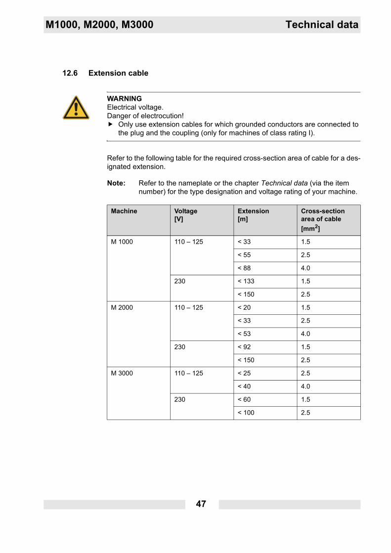
12.6 Extension cable
Refer to the following table for the required cross-section area of cable for a des-ignated extension.
Note: Refer to the nameplate or the chapter Technical data (via the item number) for the type designation and voltage rating of your machine.
WARNINGElectrical voltage.Danger of electrocution!
Only use extension cables for which grounded conductors are connected to the plug and the coupling (only for machines of class rating I).
Machine Voltage [V]
Extension [m]
Cross-section area of cable[mm2]
M 1000 110 – 125 < 33 1.5
< 55 2.5
< 88 4.0
230 < 133 1.5
< 150 2.5
M 2000 110 – 125 < 20 1.5
< 33 2.5
< 53 4.0
230 < 92 1.5
< 150 2.5
M 3000 110 – 125 < 25 2.5
< 40 4.0
230 < 60 1.5
< 100 2.5
48
Technical data M1000, M2000, M3000
Extension cable for the US market:
ExampleYou utilize a M2000/110 - 125 V and want to use an extension cable with a length of 25 m (80 ft).The machine has an input voltage of 110 – 125 V.According to the table, the extension cable must feature a cross-section area of 2.5 mm2 (AWG 14).
Note: Only use extension cables > 5 m (17 ft).
Machine Voltage [V]
Extension [ft]
Cross-section area of cable [AWG]
M 1000 110 – 125 < 96 16
< 151 14
< 239 12
M 2000 110 – 125 < 57 16
< 91 14
< 143 12
< 227 10
M 3000 110 – 125 < 68 14
< 107 12
< 170 10
M1000, M2000, M3000 Technical data
49
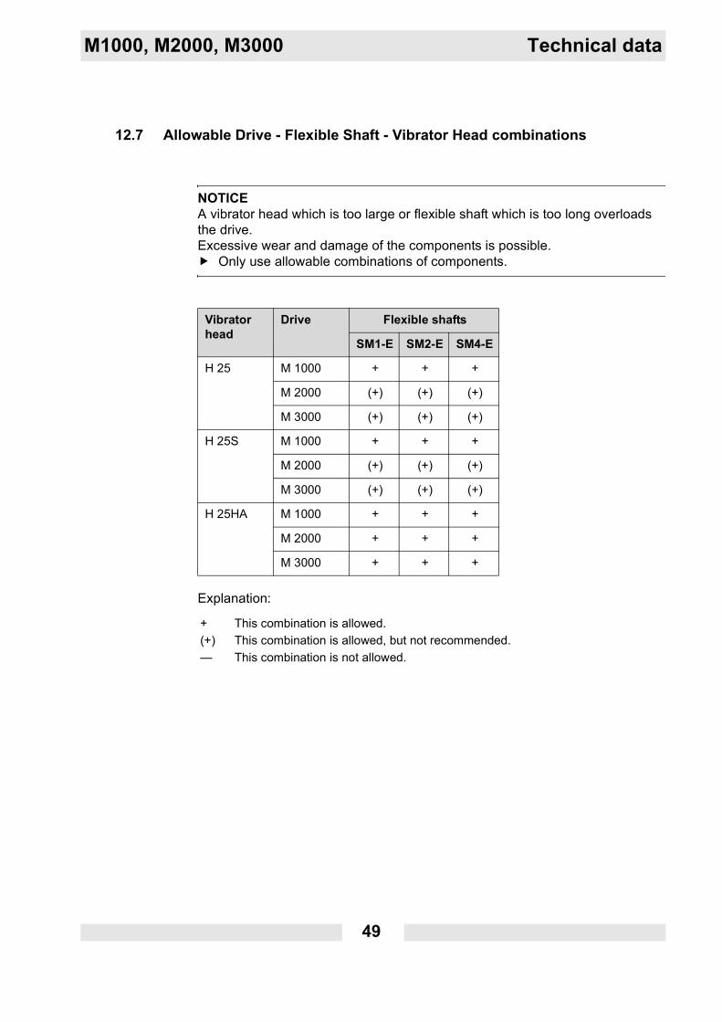
12.7 Allowable Drive - Flexible Shaft - Vibrator Head combinations
Explanation:
NOTICEA vibrator head which is too large or flexible shaft which is too long overloads the drive.Excessive wear and damage of the components is possible.
Only use allowable combinations of components.
Vibrator head
Drive Flexible shafts
SM1-E SM2-E SM4-E
H 25 M 1000 + + +
M 2000 (+) (+) (+)
M 3000 (+) (+) (+)
H 25S M 1000 + + +
M 2000 (+) (+) (+)
M 3000 (+) (+) (+)
H 25HA M 1000 + + +
M 2000 + + +
M 3000 + + +
+ This combination is allowed.(+) This combination is allowed, but not recommended.— This combination is not allowed.
50
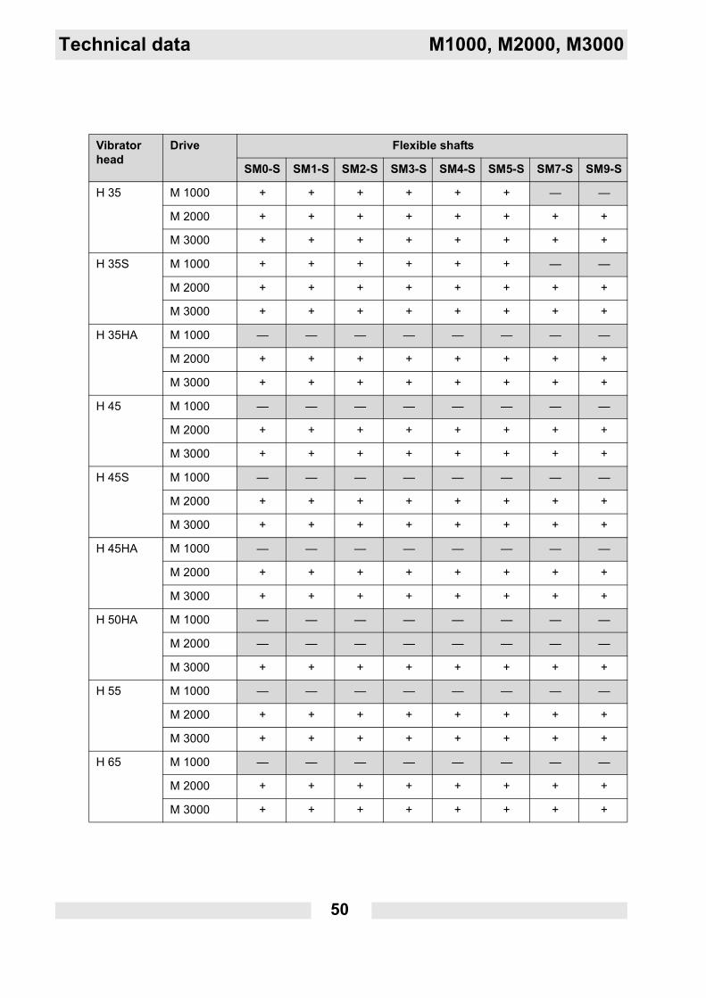
Technical data M1000, M2000, M3000
Vibrator head
Drive Flexible shafts
SM0-S SM1-S SM2-S SM3-S SM4-S SM5-S SM7-S SM9-S
H 35 M 1000 + + + + + + — —
M 2000 + + + + + + + +
M 3000 + + + + + + + +
H 35S M 1000 + + + + + + — —
M 2000 + + + + + + + +
M 3000 + + + + + + + +
H 35HA M 1000 — — — — — — — —
M 2000 + + + + + + + +
M 3000 + + + + + + + +
H 45 M 1000 — — — — — — — —
M 2000 + + + + + + + +
M 3000 + + + + + + + +
H 45S M 1000 — — — — — — — —
M 2000 + + + + + + + +
M 3000 + + + + + + + +
H 45HA M 1000 — — — — — — — —
M 2000 + + + + + + + +
M 3000 + + + + + + + +
H 50HA M 1000 — — — — — — — —
M 2000 — — — — — — — —
M 3000 + + + + + + + +
H 55 M 1000 — — — — — — — —
M 2000 + + + + + + + +
M 3000 + + + + + + + +
H 65 M 1000 — — — — — — — —
M 2000 + + + + + + + +
M 3000 + + + + + + + +
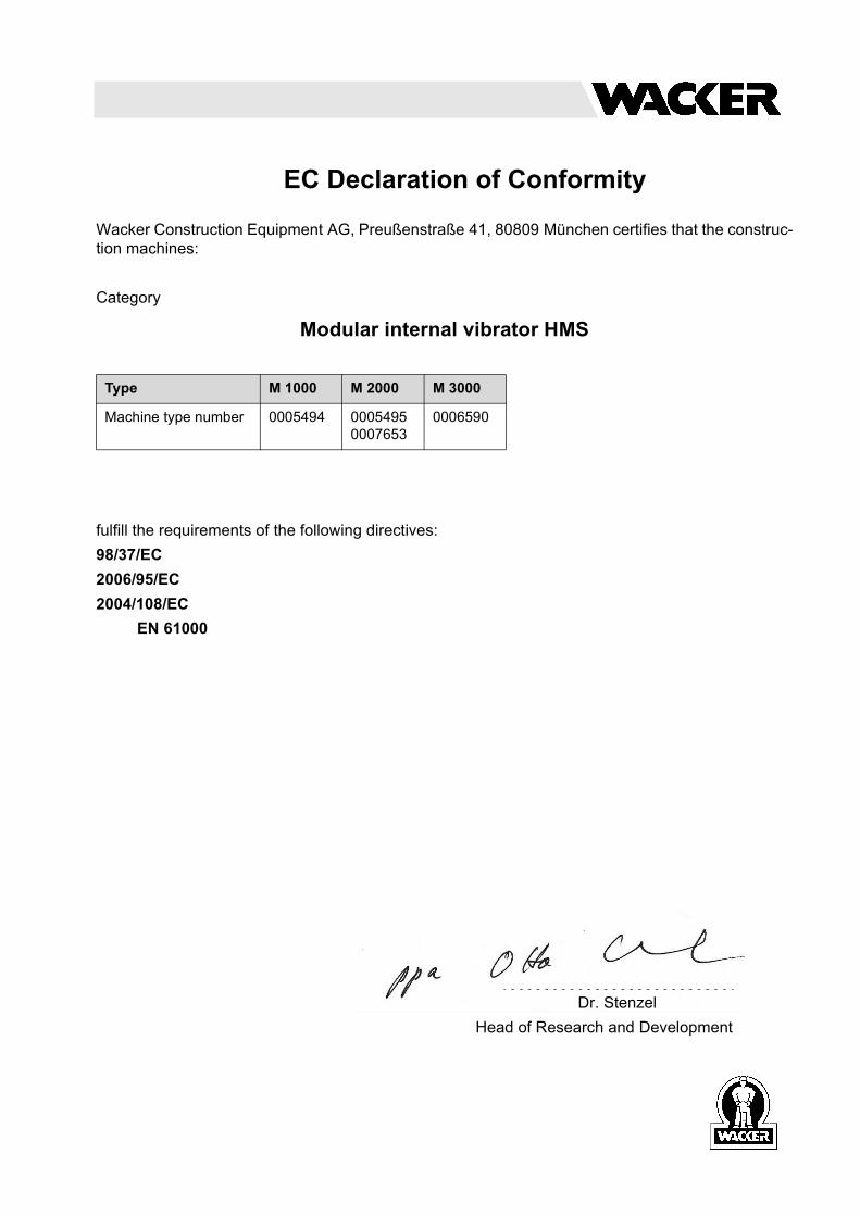
EC Declaration of Conformity
Wacker Construction Equipment AG, Preußenstraße 41, 80809 München certifies that the construc-tion machines:
Category
Modular internal vibrator HMS
fulfill the requirements of the following directives:98/37/EC2006/95/EC2004/108/EC
EN 61000
Type M 1000 M 2000 M 3000
Machine type number 0005494 0005495 0007653
0006590
Dr. StenzelHead of Research and Development

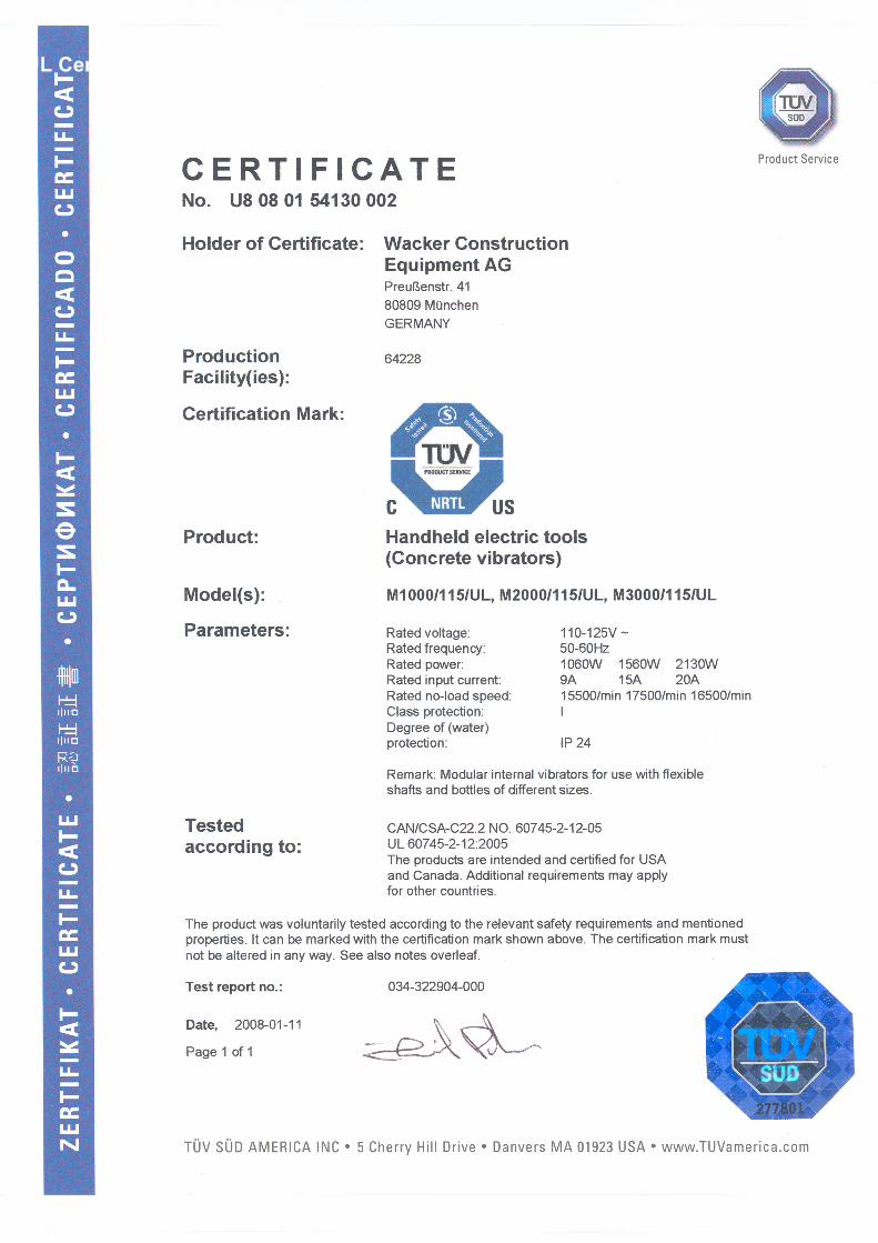
UL Certificate

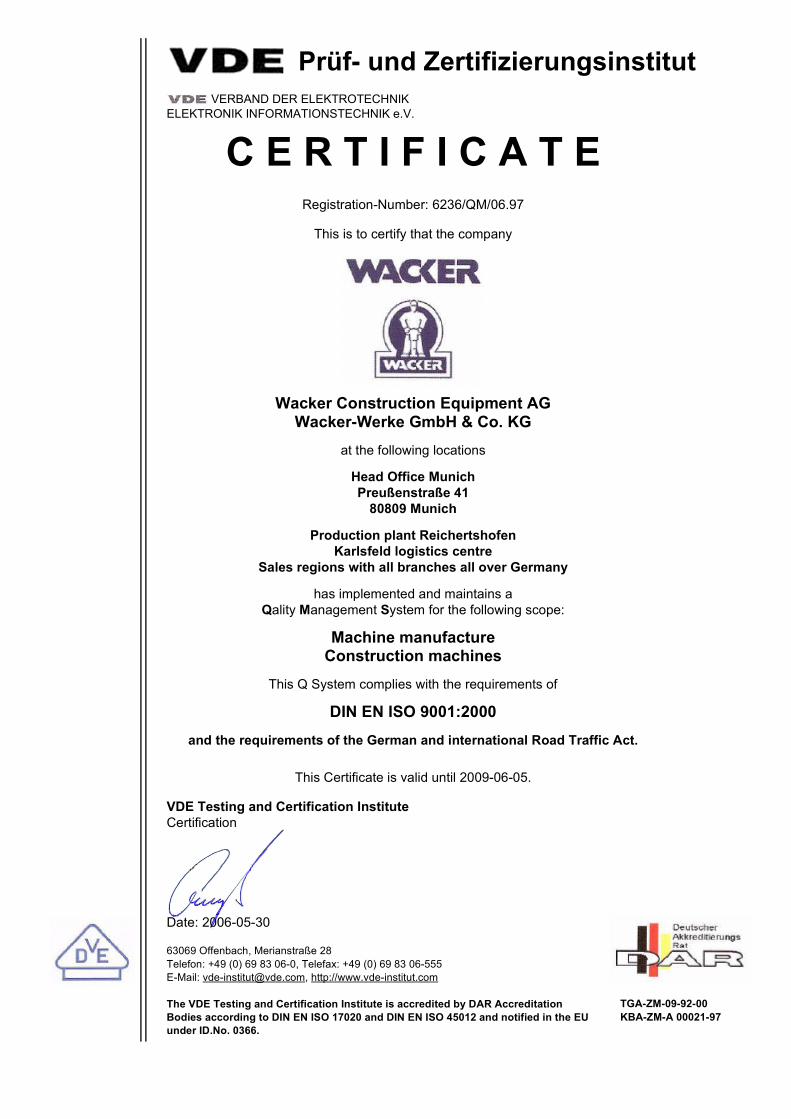
Prüf- und Zertifizierungsinstitut VERBAND DER ELEKTROTECHNIK
ELEKTRONIK INFORMATIONSTECHNIK e.V.
C E R T I F I C A T ERegistration-Number: 6236/QM/06.97
This is to certify that the company
Wacker Construction Equipment AGWacker-Werke GmbH & Co. KG
at the following locations
Head Office MunichPreußenstraße 41
80809 Munich
Production plant ReichertshofenKarlsfeld logistics centre
Sales regions with all branches all over Germany
has implemented and maintains a Qality Management System for the following scope:
Machine manufactureConstruction machines
This Q System complies with the requirements of
DIN EN ISO 9001:2000and the requirements of the German and international Road Traffic Act.
This Certificate is valid until 2009-06-05.
VDE Testing and Certification InstituteCertification
Date: 2006-05-30
63069 Offenbach, Merianstraße 28Telefon: +49 (0) 69 83 06-0, Telefax: +49 (0) 69 83 06-555E-Mail: [email protected], http://www.vde-institut.com
The VDE Testing and Certification Institute is accredited by DAR AccreditationBodies according to DIN EN ISO 17020 and DIN EN ISO 45012 and notified in the EUunder ID.No. 0366.
TGA-ZM-09-92-00KBA-ZM-A 00021-97
DIN EN ISO 9001 Certificate

Wacker Construction Equipment AG, Preußenstraße 41, 80809 München – Deutschland – Tel.: +49-(0)89-354 02-0 – Fax: +49-(0)89-354 02-390Wacker Corporation – P.O. Box 9007 – Menomonee Falls, WI 53052-9007 – USA – Tel.: +1(1)262-255-0500 – Fax: +1(1)262-255-0550 – Support: 800-770-0957Wacker Machinery (HK) Ltd.– Skyline Tower, Suite 2303, 23/F – 39 Wang Kwong Road, Kowloon Bay – Hong Kong – Tel.: +852-3188-5506, Fax: +852-2406-6021