Embed Size (px)
Citation preview

TECHNICAL MANUAL
DSC2
Issued by :
ICS Electronics Ltd
Unit V
Rudford Industrial Estate Ford, Arundel West-Sussex BN18 0BD
MODULAR GMDSS
COMMUNICATIONS SYSTEM

II
DSC2 Technical Manual GENERAL
12/06/07
II
IMPORTANT
Servicing the DSC2 system is limited to exchanging the defective ‘Module’ and returning this module to ICS Electronics Ltd. for repairs. This manual does not include
diagrams or parts lists for this reason. Any attempt to repair a ‘Module’ or modify its content may cause harmful interference
and will render any existing warranty void.
No part of this document may be reproduced or transmitted in any form or by any means, electronic or mechanical, for any purpose, without the express written
permission of ICS Electronics Ltd.
The information in this document is provided for reference only. ICS Electronics Limited does not assume any liability arising out of the application or
use of the information or products described herein.
© 1996 ICS Electronics Limited. All rights reserved

III
DSC2 Technical Manual GENERAL
12/06/07
III
This page left intentionally blank.
IV
DSC2 Technical Manual GENERAL
12/06/07
IV
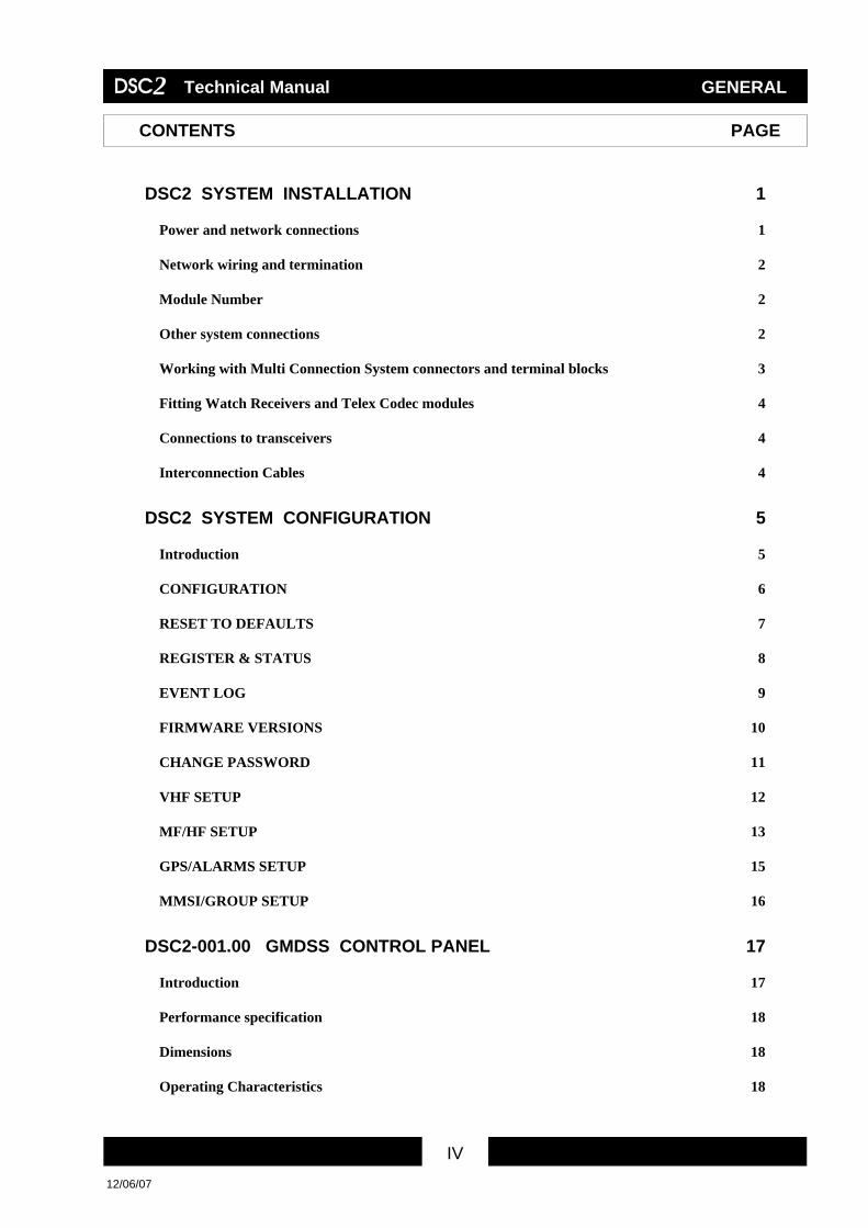
CONTENTS PAGE
DSC2 SYSTEM INSTALLATION 1
Power and network connections 1
Network wiring and termination 2
Module Number 2
Other system connections 2
Working with Multi Connection System connectors and terminal blocks 3
Fitting Watch Receivers and Telex Codec modules 4
Connections to transceivers 4
Interconnection Cables 4
DSC2 SYSTEM CONFIGURATION 5
Introduction 5
CONFIGURATION 6
RESET TO DEFAULTS 7
REGISTER & STATUS 8
EVENT LOG 9
FIRMWARE VERSIONS 10
CHANGE PASSWORD 11
VHF SETUP 12
MF/HF SETUP 13
GPS/ALARMS SETUP 15
MMSI/GROUP SETUP 16
DSC2-001.00 GMDSS CONTROL PANEL 17
Introduction 17
Performance specification 18
Dimensions 18
Operating Characteristics 18

V
DSC2 Technical Manual GENERAL
12/06/07
V
CONTENTS PAGE
Indicators & Fuses 18
Network 18
Display 18
Controls 18
Auxiliary alarm output 18
Printer output 19
Connections 20
Access area 21
Control Panel outline & dimensions 22
Certificate of Type Approval 23
DSC2-002.00 GMDSS VHF DSC MODEM 25
Introduction 25
Performance specification 25
Dimensions 25
Operating Characteristics 26
Indicators & Fuses 26
Network 26
Connections to transceiver 26
DSC modulation index 27
Connectors 27
Network termination & Unit Number links 28
Module outline & dimensions 28
Module outline & dimensions 29
Certificate of Type Approval 30
DSC2-002.02 VHF DSC/AIS MODEM 32
Introduction 32
Performance specification 32

VI
DSC2 Technical Manual GENERAL
12/06/07
VI
CONTENTS PAGE
AIS operation 32
Dimensions 33
Operating Characteristics 33
Indicators & Fuses 33
Network 33
DSC modulation index 33
Connections to transceiver 34
Connectors 34
Network termination & Unit Number links 35
Module outline & dimensions 36
DSC2-003.00 GMDSS MF/HF DSC MODEM 37
Introduction 37
Performance specification 37
Dimensions 37
Operating Characteristics 38
Indicators & Fuses 38
Network 38
Connections to transceiver 38
Connectors 39
Network termination & Unit Number links 40
Module outline & dimensions 41
Certificate of Type Approval 42
DSC2-003.01 GMDSS MF DSC MODEM 44
Introduction 44
Performance specification 44
Dimensions 44
Operating Characteristics 45

VII
DSC2 Technical Manual GENERAL
12/06/07
VII
CONTENTS PAGE
Indicators & Fuses 45
Network 45
Operational characteristics 45
Connections to transceiver 45
Connectors 46
Network termination & Unit Number links 47
Module outline & dimensions 47
Module outline & dimensions 48
Certificate of Type Approval 49
DSC2-004.00 GMDSS VHF CH70 WATCH RECEIVER 52
Introduction 52
Performance specification 52
Dimensions 52
Indicators & Fuses 52
Network 53
Operating Characteristics 53
Connections 53
Module outline & dimensions 54
Certificate of Type Approval 55
DSC2-005.00 GMDSS MF/HF SCANNING WATCH RECEIVER 57
Introduction 57
Performance specification 57
Dimensions 57
Indicators & Fuses 58
Network 58
Operating Characteristics 58
Connections 59

VIII
DSC2 Technical Manual GENERAL
12/06/07
VIII
CONTENTS PAGE
Module outline & dimensions 60
Certificate of Type Approval 61
DSC2-006.00 GMDSS MF/HF TELEX CODEC 63
Introduction 63
Performance specification 63
Dimensions 63
Operating Characteristics 63
Indicators & Fuses 64
Network 64
Service link jumper 64
System connections 64
Connections 65
Network termination & Unit Number links 66
Module outline & dimensions 68
Certificate of Type Approval 69
DSC2-007.01 RT2048 GMDSS TRANSCEIVER INTERFACE 71
Introduction 71
Dimensions 71
Indicators & Fuses 71
Power 71
Network 72
Use with a DSC2-002.00 VHF DSC Modem 72
Connections for interfaces with serial numbers up to 0199 included 72
Connections for interfaces with serial numbers from 0200 onwards 73
System connection diagram 75
Network termination & Unit number links 75
Module outline & dimensions 76

IX
DSC2 Technical Manual GENERAL
12/06/07
IX
CONTENTS PAGE
DSC2-007.03 RE2100TLX GMDSS TRANSCEIVER INTERFACE 77
Introduction 77
Dimensions 77
Indicators & Fuses 77
Network 77
Power 78
System requirements 78
Sailor RE2100 set up 78
DSC2 system set up 78
Connections 79
Connections for interfaces with serial numbers up to 0199 included 79
Connections for interfaces with serial numbers from 0200 onwards 80
Network termination & Unit number links 81
Module outline & dimensions 82
DSC2-007.06 TRP3000 GMDSS TRANSCEIVER INTERFACE 84
Introduction 84
Dimensions 84
Indicators & Fuses 84
Network 84
Connections 85
Module outline & dimensions 86
DSC2-007.07 TRP7000 GMDSS TRANSCEIVER INTERFACE 87
Introduction 87
Dimensions 87
Indicators & Fuses 87
Network 87
Connections 88

X
DSC2 Technical Manual GENERAL
12/06/07
X
CONTENTS PAGE
System requirements: 89
Module outline & dimensions 89
DSC2-007.08 TRP8000 GMDSS TRANSCEIVER INTERFACE 90
Introduction 90
Dimensions 90
Operating Characteristics 90
Indicators & Fuses 90
Network 91
Audio in/out 91
PTT Input 91
PTT Output 91
Transceiver connection 91
Typical set up 91
Use with a DSC2-003 MF/HF DSC Modem 91
Connections 92
System requirements 93
Module outline & dimensions 93
DSC2-007.09 TRP9000 GMDSS TRANSCEIVER INTERFACE 94
Introduction 94
Dimensions 94
Indicators & Fuses 94
Network 94
Connections 95
System requirements 96
Module outline & dimensions 96

XI
DSC2 Technical Manual GENERAL
12/06/07
XI
CONTENTS PAGE
DSC2-007.10 IC-M710 GMDSS TRANSCEIVER INTERFACE 97
Introduction 97
Dimensions 97
Indicators & Fuses 97
Network 97
Connections 98
System requirements: 98
Operation 98
Setup of M710 for use with DSC2 98
Interconnection Cable Layout 99
Module outline & dimensions 100
DSC2-007.11 RE2100NOTLX GMDSS TRANSCEIVER INTERFACE 101
Introduction 101
Dimensions 101
Indicators & Fuses 101
Network 101
Power 102
System requirements 102
DSC2 system set up 102
Sailor RE2100 set up 103
Connections 104
Network termination & Unit number links 105
Module outline & dimensions 106
DSC2-007.12 RT2047/D GMDSS TRANSCEIVER INTERFACE 107
Introduction 107
Dimensions 107
Indicators & Fuses 107

XII
DSC2 Technical Manual GENERAL
12/06/07
XII
CONTENTS PAGE
Power 107
Network 108
Network Use with a DSC2-002.00 VHF DSC Modem 108
Connections 108
System connection diagram 110
Network termination & Unit number links 110
Module outline & dimensions 111
DSC2-007.13 RS8400 GMDSS TRANSCEIVER INTERFACE 112
Introduction 112
Dimensions 112
Indicators & Fuses 112
Network 112
Power 112
Connections 113
System requirements: 113
Operation 113
Interconnection Cable Layout 114
Module outline & dimensions 115
DSC2-008.00 GMDSS GPS / ALARM INTERFACE 117
Introduction 117
Dimensions 117
Operating Characteristics 117
Indicators & Fuses 117
Network 118
NMEA0183 GPS input 118
Alarm inputs 118
Alarm outputs 118

XIII
DSC2 Technical Manual GENERAL
12/06/07
XIII
CONTENTS PAGE
Alarm power 118
Alarm set up 118
Connections 119
Module outline & dimensions 120
DSC2-009.00 GMDSS NETWORK ROUTER 121
Introduction 121
Dimensions 121
Operating Characteristics 121
Indicators & Fuses 121
The Network Router and the single fault principle. 122
Typical DSC2 combination for Sea Area A3, using Duplication 122
Network 124
Module outline & dimensions 125
Connections 125
DSC2-010.00 GMDSS MF/HF TELEX PC INTERFACE 126
Introduction 126
Performance specification 126
Dimensions 126
Operating Characteristics 126
Indicators & Fuses 126
Network 127
Connections 127
Connection cable to PC 127
Network termination & Unit number links 128
Certificate of Type Approval 129
Module outline & dimensions 131
XIV
DSC2 Technical Manual GENERAL
12/06/07
XIV
CONTENTS PAGE
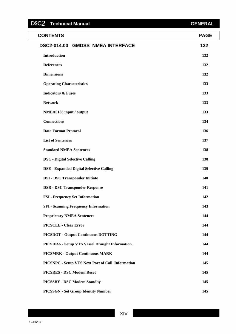
DSC2-014.00 GMDSS NMEA INTERFACE 132
Introduction 132
References 132
Dimensions 132
Operating Characteristics 133
Indicators & Fuses 133
Network 133
NMEA0183 input / output 133
Connections 134
Data Format Protocol 136
List of Sentences 137
Standard NMEA Sentences 138
DSC - Digital Selective Calling 138
DSE - Expanded Digital Selective Calling 139
DSI - DSC Transponder Initiate 140
DSR - DSC Transponder Response 141
FSI - Frequency Set Information 142
SFI - Scanning Frequency Information 143
Proprietary NMEA Sentences 144
PICSCLE - Clear Error 144
PICSDOT - Output Continuous DOTTING 144
PICSDRA - Setup VTS Vessel Draught Information 144
PICSMRK - Output Continuous MARK 144
PICSNPC - Setup VTS Next Port of Call Information 145
PICSRES - DSC Modem Reset 145
PICSSBY - DSC Modem Standby 145
PICSSGN - Set Group Identity Number 145

XV
DSC2 Technical Manual GENERAL
12/06/07
XV
CONTENTS PAGE
PICSSMN - Set MMSI Number 146
PICSSPC - Output Continuous SPACE 146
PICSSTA - Enable/Disable NMEA Status Output 146
PICSSxx - DSC Module Status 147
PICSTWX - Frequency Control 149
PICSTYP - Setup VTS Sub Type Information 149
PICSVTS - Setup VTS Transponder Information 149
PICSWPT - Setup VTS Waypoint Information 150
PICSWRX - DSC Receive Frequency and Address Information 150

1
DSC2 Technical Manual General
Issued 20/11/98 Doc. Ref: 0131 © Copyright ICS 19981
DSC2 SYSTEM INSTALLATION This guide assumes the installer has prior knowledge of the configuration of the system and the modules to be installed.
Power and network connections Determine which modules require power and/or network connection from the following table:
Module Type Power requirements Network Voltage Current connection DSC2-001.00 Control Panel 10.8 - 31.2 Vdc 2.0 A Yes DSC2-002.00 VHF DSC Modem 10.8 - 31.2 Vdc 1.6 A Yes DSC2-003.00 MF/HF DSC Modem 10.8 - 31.2 Vdc 1.6 A Yes DSC2-003.01 MF DSC Modem 10.8 - 31.2 Vdc 1.6 A Yes DSC2-004.00 VHF Watch Receiver powered from VHF DSC Modem No DSC2-005.00 MF/HF Scanning Watch Receiver powered from MF/HF DSC Modem No DSC2-006.00 MF/HF Telex Codec powered from MF/HF DSC Modem Yes DSC2-007.01 RT2048 Transceiver Interface powered from RT2048 Yes DSC2-007.03 RE2100tlx Transceiver Interface powered from RE2100 Yes DSC2-007.06 TRP3000 Transceiver Interface powered from TRP3000 Yes DSC2-007.07 TRP7000 Transceiver Interface powered from TRP7000 Yes DSC2-007.08 TRP8000 Transceiver Interface powered from TRP8000 Yes DSC2-007.09 TRP9000 Transceiver Interface powered from TRP9000 Yes DSC2-007.10 M710 Transceiver Interface powered from M710 Yes DSC2-007.11 RE2100notlx Transceiver Interface powered from RE2100 Yes DSC2-007.12 RT2047/D Transceiver Interface powered from RT2047/D Yes DSC2-008.00 GPS/Alarm Interface 10.8 - 31.2 Vdc 0.5 A Yes DSC2-009.00 Network Router 10.8 - 31.2 Vdc 0.5 A Yes DSC2-010.00 MF/HF Telex PC Interface 10.8 - 31.2 Vdc 0.5 A Yes
All modules requiring network or power connection, excluding the Control Panels and Printers, use a standard 6 way connector, supplied with the modules. The pin assignment is as follows:
NETWORK/POWER connector
1 Network Data B 2 Network Data A 3 Not used 4 Not used 5 Power Supply negative 6 Power Supply positive
An earth stud is provided adjacent to this connector.
The Control Panels use a way terminal block with the terminal numbers marked. See Control Panel technical information for connection details.

2
DSC2 Technical Manual General
Issued 20/11/98 Doc. Ref: 0131 © Copyright ICS 19982
Network wiring and termination
The network connections of the respective modules must form a daisy chain with the two ends terminated. A shielded, twisted pair data cable capable of supporting communications at 1.25 Mb/s must be used (see “Interconnection Cables” at the end of this section)
Network terminators are included in all modules with a network connection and these may be enabled or disabled via a jumper link. Prior to installation determine which modules require the terminators to be enabled (i.e. modules at either end of a network) and set these accordingly (link fitted) The default setting is disabled (link not fitted).
Excluding the Control Panel and Printer, the network termination link is located inside the modules adjacent to the ‘POWER/NETWORK’ connector. Refer to the specific module technical information for details.
The Control Panel network termination link is accessible via the rear access plate.
Module Number
All modules connected to the network have a set of module number links which must be set prior to installation of the modules. The default setting is Module Number 1 for all modules.
If a second module of the same type is connected to the same network (including networks divided by routers) then it's module number should be set to Module Number 2. Likewise a third module of the same type connected to the same network should be set to Module Number 3.
Modules that are logically linked through the network must have the same Module Number setting. The logical links are as follows:- VHF DSC Modem and VHF Transceiver Interface MF/HF DSC Modem and MF/HF Transceiver Interface Telex Codec and Telex PC Interface
Examples: VHF DSC Modem Module Number 1 linked with VHF Transceiver Interface Module Number 1 VHF DSC Modem Module Number 2 linked with VHF Transceiver Interface Module Number 2
See individual module information for location and setting of module number links.
Other system connections Refer to the relevant module technical information for details.

3
DSC2 Technical Manual General
Issued 20/11/98 Doc. Ref: 0131 © Copyright ICS 19983
Working with Multi Connection System connectors and terminal blocks
Three types of connectors are used in the DSC2 system: * BNC connectors for MF, HF and VHF aerial connections * Sub-D connectors (DB9, DB15, DB25, etc.) * Multi System Connectors (MSC). These connectors have an orange color.
The Multi System Connectors (MSC) are used for NETWORK/POWER, AUDIO/CONTROL and GPS/Alarm input/output connections.
Multi-stranded wires from 0.08 mm2 up to 2.50 mm2 can be inserted in and extracted from the MSC connector or terminal block by using an operating lever or a simple screwdriver of the appropriate size. If more than one wire has to go into one connection point, care should be taken that the wires are properly twisted together before inserting them into the connector. If this is not possible, a suitable insulated crimp terminal must be used to bond the wires together before insertion into the terminal block or connector.
4
DSC2 Technical Manual General
Issued 20/11/98 Doc. Ref: 0131 © Copyright ICS 19984
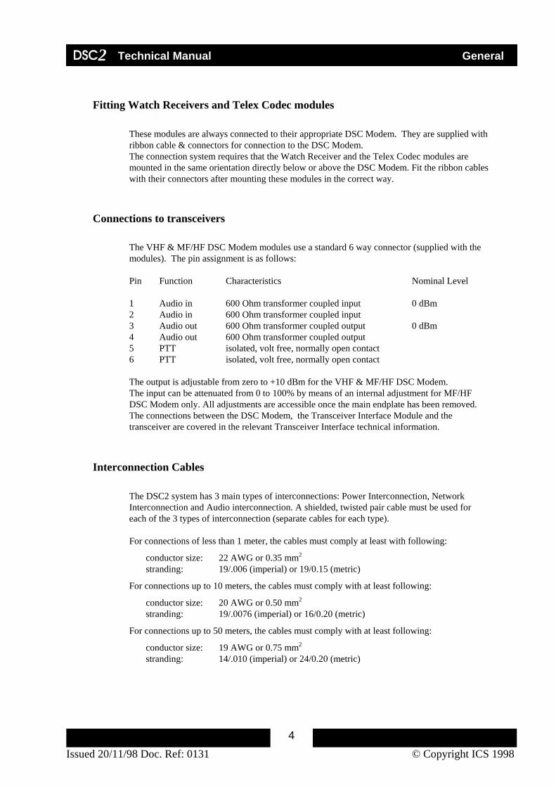
Fitting Watch Receivers and Telex Codec modules These modules are always connected to their appropriate DSC Modem. They are supplied with
ribbon cable & connectors for connection to the DSC Modem. The connection system requires that the Watch Receiver and the Telex Codec modules are
mounted in the same orientation directly below or above the DSC Modem. Fit the ribbon cables with their connectors after mounting these modules in the correct way.
Connections to transceivers
The VHF & MF/HF DSC Modem modules use a standard 6 way connector (supplied with the modules). The pin assignment is as follows: Pin Function Characteristics Nominal Level 1 Audio in 600 Ohm transformer coupled input 0 dBm 2 Audio in 600 Ohm transformer coupled input 3 Audio out 600 Ohm transformer coupled output 0 dBm 4 Audio out 600 Ohm transformer coupled output 5 PTT isolated, volt free, normally open contact 6 PTT isolated, volt free, normally open contact The output is adjustable from zero to +10 dBm for the VHF & MF/HF DSC Modem. The input can be attenuated from 0 to 100% by means of an internal adjustment for MF/HF DSC Modem only. All adjustments are accessible once the main endplate has been removed. The connections between the DSC Modem, the Transceiver Interface Module and the transceiver are covered in the relevant Transceiver Interface technical information.
Interconnection Cables The DSC2 system has 3 main types of interconnections: Power Interconnection, Network Interconnection and Audio interconnection. A shielded, twisted pair cable must be used for each of the 3 types of interconnection (separate cables for each type). For connections of less than 1 meter, the cables must comply at least with following:
conductor size: 22 AWG or 0.35 mm2 stranding: 19/.006 (imperial) or 19/0.15 (metric)
For connections up to 10 meters, the cables must comply with at least following:
conductor size: 20 AWG or 0.50 mm2 stranding: 19/.0076 (imperial) or 16/0.20 (metric)
For connections up to 50 meters, the cables must comply with at least following:
conductor size: 19 AWG or 0.75 mm2 stranding: 14/.010 (imperial) or 24/0.20 (metric)

DSC2 Technical Manual GENERAL
20/11/98
5
DSC2 SYSTEM CONFIGURATION
Introduction The configuration process of the DSC2 system sets up all the Control Panels in the system to ensure correct operation with all available DSC2 modules. The configuration operation must be carried out by the installation engineer when the system is installed or when any major changes are required. The configuration options of the DSC2 are protected by a password to prevent unauthorized access. The configuration process specifies which modules are available for use within the DSC2 system and sets up the operating characteristics of the system. Any changes made to the configuration settings will be sent to all the Control Panels that are present on the network. Whilst in the ‘CONFIGURATION’ menu, it will not be possible to send any type of DSC call or respond to any new calls. The configuration menu is entered by selecting the ‘CONFIGURATION’ option in the DSC2 menu. Access to the configuration menu is password protected. Once the correct configuration password has been entered a warning message is displayed indicating that it will not be possible to send any distress alerts or call or see any new calls whilst in the configuration mode.
If ‘Yes’ is selected, the ‘CONFIGURATION’ menu will be entered.

DSC2 Technical Manual GENERAL
20/11/98
6
CONFIGURATION
The ‘CONFIGURATION’ menu options perform the following functions:
RESET TO DEFAULTS Sets configuration options to factory defaults. REGISTER & STATUS Registers & shows the status of the registered modules. EVENT LOG Displays a log of all DSC2 module faults and events. FIRMWARE VERSIONS Displays the firmware versions of the DSC2 modules. CHANGE PASSWORD Change the configuration menu password. VHF SETUP Sets up the VHF transceiver system operation. MF/HF SETUP Sets up the MF/HF transceiver system operation. GPS/ALARMS SETUP Sets up the GPS/ALARM input and output alarms. MMSI/GROUP SETUP Sets/Changes the system MMSI and group identities. Cancel Displays the following confirmation prompt before
exiting the configuration menu:
. Each of the configuration menu options will now be described in more detail.

DSC2 Technical Manual GENERAL
20/11/98
7
RESET TO DEFAULTS This menu allows the reset all of the configuration and preference
settings of the control panel. The reset information is listed below:
All DSC2 modules are set to ‘not registered’
. ` Configuration menu password is set to: ‘999999’
. All transceivers are set to automatic tuning.
. ‘Channel tuning’ on MF/HF is disabled. All Preference options are reset to default settings.
The Message Log is cleared.
The Call Directory is cleared.
All GPS/ALARM alarms are cleared. MMSI and Group identities are reset to: ‘999999999’
As this operation clears the MMSI and groups identities, the link
LK12, which is described under the ‘MMSI/GROUP SETUP’ option, must be set on the Control Panel circuit board before this option can be carried out.
The ‘MMSI/GROUP SETUP’ menu option will be automatically entered, once the reset operation has been carried out When this operation has been completed, the reset configuration data is transmitted to all the control panels currently present on the network.

DSC2 Technical Manual GENERAL
20/11/98
8
REGISTER & STATUS This menu allows to ‘REGISTER’ the modules connected to the
DSC2 system and shows the status of all the DSC2 modules currently present on the system. The display indicates which modules are registered, shows if any modules are indicating a fault and displays the ‘status word’ for modules currently present on the network.
The ‘REGISTER & STATUS’ menu is displayed on up to 4 pages.
The first page shows the status of the Control Panels present in the system. If VHF modules are registered or are present on the network the next page shows the status of these modules.
If there are no VHF modules, this page is not displayed. If MF/HF modules are registered or are present on the network the next page shows the status of these modules.
If there are no MF/HF modules, this page is not displayed.
The final page shows the status of any Telex, GPS/Alarm and Printer modules that are registered or are present on the network. The ‘REGISTER’ button will set as ‘Registered’ all modules that are currently seen on the network and are indicating no errors. From this point on only these modules will be available for use by the system. In addition, only faults present on these modules will be reported. Before this selection is made the installation engineer must ensure that all the required equipment is present on the system and indicating no faults.

DSC2 Technical Manual GENERAL
20/11/98
9
EVENT LOG This menu shows any system faults or other events that have occurred
in the DSC2 system.
The ‘EVENT LOG’ indicates module failures, the recovery of modules that reported a fault and events such as ‘GPS/Alarm Interface’ alarms.
A ‘√ ‘ symbol displayed next to a Fault indicates that this module is no longer showing a fault indication. The ‘Clear Log’ button allows the contents of the ‘EVENT LOG’ to be cleared.

DSC2 Technical Manual GENERAL
20/11/98
10
FIRMWARE VERSIONS This menu displays the versions of firmware build into the DSC2
modules that are currently present on the network.
The ‘FIRMWARE VERSIONS’ menu is displayed on up to 4 pages.
The first page shows the firmware versions of the Control Panels currently on the system. If VHF modules are registered or are present on the network, the next page shows the firmware versions of these modules.
If there are no VHF modules, this page is not displayed. If MF/HF modules are registered or are present on the network, the next page shows the firmware versions of these modules.
If there are no MF/HF modules, this page is not displayed.
The final page shows the firmware versions of any Telex, GPS/Alarm and Printer modules that are present on the network.

DSC2 Technical Manual GENERAL
20/11/98
11
CHANGE PASSWORD This menu allows the CONFIGURATION menu access password to
be changed. The password is a 6 digit number. The new password is transmitted to all the control panels on the network, so that it is the same for all of the control panels. When this option is selected, the password set-up screen is displayed:
If a new password is entered the following screen is displayed allowing the new password to be confirmed.

DSC2 Technical Manual GENERAL
20/11/98
12
VHF SETUP This menu allows the operating configuration of the VHF part of the
system to be set up. If no VHF transceivers are registered, this menu option is not displayed:
Tx/Rx CONTROL allows VHF transceiver systems to be set to MANUAL or AUTOMATIC (default) tuning. Before changing the Tx/Rx CONTROL for the transceiver, ensure that the selection matches the operating characteristics of the VHF transceiver interface. Select MANUAL when no transceiver interface is fitted.
AUTO ACKNOWLEDGE will enable non distress calls requiring an acknowledgment to be automatically acknowledged. The automatic acknowledge operation will only be carried out if the VHF transceiver system is not in use, the Tx/ Rx CONTROL is set for automatic tuning and the transceiver is not currently tuned to a DSC distress and safety frequency,.
DOTTING TEST, SPACE TEST, MARK TEST allows a dotting,
space or mark test to be carried out on a VHF transceiver system. RESET DSC allows VHF DSC modules to be reset.
ACCEPT OWN MMSI enables a test mode allowing calls to be received that were transmitted using the system’s own MMSI. Once the option selected, the button changes to ‘REJECT OWN MMSI’ allowing the test mode to be switched off.

DSC2 Technical Manual GENERAL
20/11/98
13
MF/HF SETUP This menu allows the operating configuration of the MF/HF part of
the system to be set up. If no MF/HF transceivers are registered, this menu option is not displayed:
Tx/Rx CONTROL allows MF/HF transceiver systems to be set for MANUAL or AUTOMATIC (default) tuning. Before changing the Tx/Rx CONTROL for the transceiver, ensure that the selection matches the operating characteristics of the MF/HF transceiver interface. Select MANUAL when no transceiver interface is fitted.
CHANNEL SETUP allows channel selection for DSC calls made
using this transceiver. This setting enables normal MF/HF channel operation and recommendation M.586 channel operation. Before changing CHANNEL SETUP for the transceiver, ensure that the selection matches the operating characteristics of the MF/HF transceiver interface. Default setting is NO CHANNEL TUNE. AUTO ACKNOWLEDGE enables non distress calls requiring an acknowledgment to be automatically acknowledged. The operation will only be carried out if the MF/HF transceiver system is not in use, the Tx/ Rx CONTROL is set for automatic tuning and the transceiver is not currently tuned to a DSC distress and safety frequency,.
CHANGE SEA AREA enables the setting of the current sea area to
A2 or A3. The MF/HF Watch receiver frequency table will be set according to the selected sea area. On a multi-control panel installation it is important to note that all control panels should be connected and fully functional before changing sea areas to enable the correct synchronization of watch receiver frequency tables.
DOTTING TEST, SPACE TEST, MARK TEST allows a dotting, space or mark test to be carried out on a MF/HF transceiver system. RESET DSC allows MF/HF DSC modules to be reset.

DSC2 Technical Manual GENERAL
20/11/98
14
ACCEPT OWN MMSI enables a test mode allowing calls to be received that were transmitted using the system’s own MMSI. Once the option selected, the button changes to ‘REJECT OWN MMSI’ allowing the test mode to be switched off.

DSC2 Technical Manual GENERAL
20/11/98
15
GPS/ALARMS SETUP This menu allows the alarm inputs and outputs provided in the
GPS/Alarm modules to be set up. If no GPS/Alarm modules are registered, a warning message will be displayed:
If GPS/Alarm modules are registered the following set-up page will be displayed for each of the GPS/Alarm modules that are available:
Alarm inputs can be set-up to reflect an incoming INMARSAT EGC,
a NAVTEX alert or a text string specified by the user and become active on closure of their respective input contact. The input alarms can be set to normal priority, which sounds a warning beep and displays the alarm, or high priority which sounds the control panel siren.
Alarm outputs can be set for an INMARSAT distress transmission or
can be used for the transmission of DSC distress alerts or calls. The alarm outputs can be set to be active for 1 to 9 seconds or for the duration of the event.

DSC2 Technical Manual GENERAL
20/11/98
16
MMSI/GROUP SETUP This menu allows the 9 digit MMSI and group identities of the DSC
system to be set up. The MMSI value must be set to the vessels MMSI, as this will be included in all DSC calls to show the identity of the sender. It is also used in identifying calls to this vessel.
If the vessel belongs to one or more group MMSI’s - also known as ‘Ships Having Common Interest’ - these can also be specified. This will ensure that calls addressed to these groups are received. Since the MMSI and groups identities are very important, a special link -LK 12 - has to be set on the Control Panel circuit board before this menu can be entered. If this link is not made when this option is selected the following error message is displayed:
Otherwise the following menu is displayed which allows the MMSI
and each of the group MMSI’s to be changed.

DSC2 Technical Manual GMDSS Control Panel
Issued 20/11/98 Doc. Ref: 0240 © Copyright ICS 199817
DSC2-001.00 GMDSS Control Panel
Front View
Rear View
DISTRESS
ENTER
BRIGHTNESS
CONTRAST
DSC GMDSS Control Panel2
ICS
Introduction The DSC2-001.00 Control Panel is the heart of the modular DSC2 system. It provides the user interface for all of the elements of a full DSC2 system. Most functions are performed on a 120 x 90 mm transmissive FSTN LCD display Touchscreen LCD display. Four dedicated buttons including a protected ‘DISTRESS’ button provide other key functions. Only relevant information and control buttons for a given operation are presented to the operator, and the display is large enough to show a complete incoming DSC message of any complexity and complete selection menus for many functions.
DSC2 Technical Manual GMDSS Control Panel
Issued 20/11/98 Doc. Ref: 0240 © Copyright ICS 199818
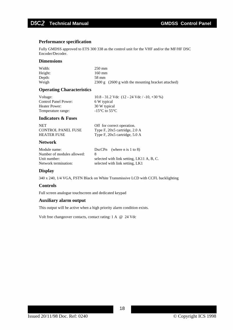
Performance specification Fully GMDSS approved to ETS 300 338 as the control unit for the VHF and/or the MF/HF DSC Encoder/Decoder.
Dimensions Width: 250 mm Height: 160 mm Depth: 58 mm Weigh 2300 g (2600 g with the mounting bracket attached)
Operating Characteristics Voltage: 10.8 - 31.2 Vdc (12 - 24 Vdc / -10, +30 %) Control Panel Power: 6 W typical Heater Power: 30 W typical Temperature range: -15°C to 55°C
Indicators & Fuses NET Off for correct operation. CONTROL PANEL FUSE Type F, 20x5 cartridge, 2.0 A HEATER FUSE Type F, 20x5 cartridge, 5.0 A
Network Module name: DscCPn (where n is 1 to 8) Number of modules allowed: 8 Unit number: selected with link setting, LK11 A, B, C. Network termination: selected with link setting, LK1
Display 340 x 240, 1/4 VGA, FSTN Black on White Transmissive LCD with CCFL backlighting
Controls Full screen analogue touchscreen and dedicated keypad
Auxiliary alarm output This output will be active when a high priority alarm condition exists. Volt free changeover contacts, contact rating: 1 A @ 24 Vdc

DSC2 Technical Manual GMDSS Control Panel
Issued 20/11/98 Doc. Ref: 0240 © Copyright ICS 199819
Printer output Units manufactured after July 1998, having serial numbers of 00100-1154 or greater, that are fitted with version 2.1 firmware or later, support logging printing of all received calls through a EIA232 interface, available on the main Terminal strip, J1. The printer output is intended for connection to an OKI ML280 Epson compatible serial printer with continuous paper roll. Whilst other printer types may be acceptable operation is not guaranteed. The EAI232 Serial interface is configured for Baud rate: 9600 Data bits 8 Stop bits 1 Parity None Flow control Xon/Xoff The control panel includes buffering for up to 10 messages to allow for the printer temporarily going offline or running out of paper.

DSC2 Technical Manual GMDSS Control Panel
Issued 20/11/98 Doc. Ref: 0240 © Copyright ICS 199820
Connections
J1
1 Network GND 2 Network Data B 3 Network Data A 4 EIA232 GND 1 5 EIA232 Rx input 1 6 EIA232 Tx output 1 7 Auxiliary alarm output (NC) 8 Auxiliary alarm output (COM) 9 Auxiliary alarm output (NO) 10 GND 11 Supply Negative 12 Supply Positive 13 Heater A ( see ‘Heater Connection’ ) 14 Heater B ( see ‘Heater Connection’ ) 15 Heater C ( see ‘Heater Connection’ ) 16 Heater D ( see ‘Heater Connection’ )
Heater connection The heater is connected differently for 12V or 24V operation as follows : 12V operation Heater A Heater supply - Heater B Heater supply + Heater C Link to Heater D Heater D Link to Heater C 24V operation Heater A Heater supply - Heater B Not used Heater C Heater supply + Heater D Not used
1 Applicable to units having serial numbers 00100-1154 and beyond.
DSC2 Technical Manual GMDSS Control Panel
Issued 20/11/98 Doc. Ref: 0240 © Copyright ICS 199821
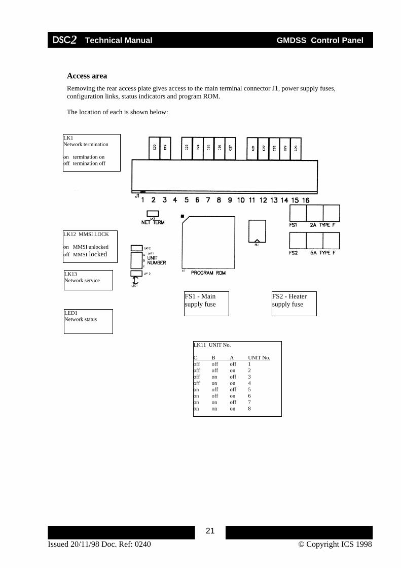
Access area Removing the rear access plate gives access to the main terminal connector J1, power supply fuses, configuration links, status indicators and program ROM. The location of each is shown below:
LK12 MMSI LOCK on MMSI unlocked off MMSI locked
LK11 UNIT No. C B A UNIT No. off off off 1 off off on 2 off on off 3 off on on 4 on off off 5 on off on 6 on on off 7 on on on 8
LED1 Network status
LK13 Network service
FS1 - Main supply fuse
FS2 - Heater supply fuse
LK1 Network termination on termination on off termination off

DSC2 Technical Manual GMDSS Control Panel
Issued 20/11/98 Doc. Ref: 0240 © Copyright ICS 199822
Control Panel outline & dimensions
250.
0
160.0
58.0
61.0
16.0
50.0 55.0M5
MO
UN
TIN
G H
OL
120.
065
.0
147.0 6.5
M4
MO
UN
TIN
G H
OLE
S
2.0
2.5
DIS
TR
ES
S
2D
SC EN
TE
R
BR
IGH
TN
ES
S
CO
NT
RA
ST

DSC2 Technical Manual GMDSS Control Panel
Issued 20/11/98 Doc. Ref: 0240 © Copyright ICS 199823
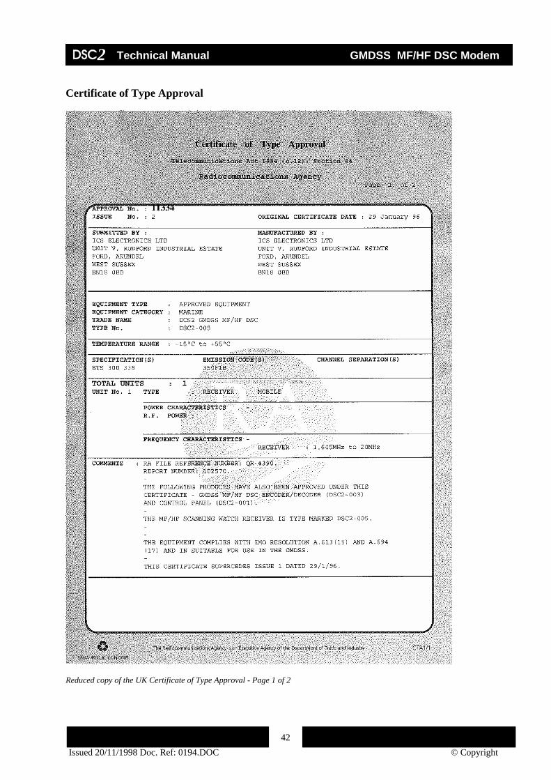
Certificate of Type Approval
Reduced copy of the UK Certificate of Type Approval - Page 1 of 2

DSC2 Technical Manual GMDSS Control Panel
Issued 20/11/98 Doc. Ref: 0240 © Copyright ICS 199824
Reduced copy of the UK Certificate of Type Approval - Page 2 of 2 Additional copies of this Certificate of Type Approval can be obtained from ICS Electronics on request.
DSC2 Technical Manual GMDSS VHF DSC Modem
Issued 20/11/98 © Copyright ICS 1998
25
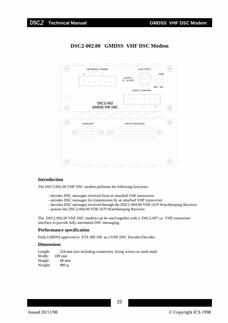
DSC2-002.00 GMDSS VHF DSC Modem
WATCH RECEIVERAUXILIARY
1
SUPPLY12 - 24 VDC
AUDIO / CONTROL
NETWORK / POWER
DSC2-002GMDSS VHF DSC
NET ON
PWR
1.6A TYPE F
1
Introduction The DSC2-002.00 VHF DSC modem performs the following functions:
- decodes DSC messages received from an attached VHF transceiver - encodes DSC messages for transmission by an attached VHF transceiver - decodes DSC messages received through the DSC2-004.00 VHF ch70 Watchkeeping Receiver - powers the DSC2-004.00 VHF ch70 Watchkeeping Receiver
The DSC2-002.00 VHF DSC modem can be used together with a DSC2-007.xx VHF transceiver interface to provide fully automated DSC messaging.
Performance specification Fully GMDSS approved to ETS 300 338 as a VHF DSC Encoder/Decoder.
Dimensions Length: 224 mm (not including connectors, fixing screws or earth stud) Width: 109 mm Height: 48 mm Weight: 980 g

DSC2 Technical Manual GMDSS VHF DSC Modem
Issued 20/11/98 © Copyright ICS 1998
26
Operating Characteristics Voltage: 10.8 - 31.2 Vdc (12 - 24 Vdc / -10%, +30 %) Power: 2 W (when used as a stand alone unit) 3 W (when used with a DSC2-004.00 connected to it) Temperature range: -15°C to 55°C
Indicators & Fuses PWR On when power connected and fuse OK. ON On when main 5V internal supply is OK. NET Off for correct operation. FUSE Type F, 20x5 cartridge, 1.6 A
Network Module name: DscVHFn (where n is 1 to 4) Number of modules allowed: 4 (maximum) Unit number: selectable via link setting, LK3 Network termination: selectable via link setting, LK1
Connections to transceiver Audio output level: Adjustable from zero to +10dBm
Nominally set for 0dBm. The output level may be adjusted by removing the main endplate and adjusting the output level potentiometer, VR3. See below.
Audio input level -10dBm to 10dBm (Tx isolated 600 Ohm impedance). PTT (Push To Talk) isolated, volt free, normally open contact Switch voltage 100 Vdc max. Switch current 0.5 Adc max. Switch power 10 W max. Where transceiver interface units are used, the connections between the DSC modem, the interface unit and the transceiver are covered in the relevant Transceiver Interface technical information.
Output level adjustment VR3

DSC2 Technical Manual GMDSS VHF DSC Modem
Issued 20/11/98 © Copyright ICS 1998
27
DSC modulation index The DSC modulation index of the complete VHF installation should be checked for conformity to the appropriate standard. Transceiver interface units are nominally set to give a modulation index of two for a DSC modem audio output setting of 0dBm. . If necessary the DSC modem’s audio output level may be adjusted as described above.
Connectors
NETWORK/POWER connector
1 Network Data B 2 Network Data A 3 Not used 4 Not used 5 Power Supply Negative 6 Power Supply Positive
AUDIO/CONTROL connector
1 Audio in (balanced 600 ohm transformer coupled input) 2 Audio in (balanced 600 ohm transformer coupled input) 3 Audio out (balanced 600 ohm transformer coupled output) 4 Audio out (balanced 600 ohm transformer coupled output) 5 PTT (isolated, volt free, normally open contact) 6 PTT (isolated, volt free, normally open contact)
WATCH RECEIVER connection (DSC2-004.00)
The ch70 Watch Receiver (DSC2-004.00) is connected to the DSC Modem with a 25 way ribbon cable assembly, which can be obtained from ICS Electronics (Pt. No. 1130.CAD).

DSC2 Technical Manual GMDSS VHF DSC Modem
Issued 20/11/98 © Copyright ICS 1998
28
Network termination & Unit Number links
LK1 NETWORK TERMINATION on termination on off termination off
LK3 UNIT No. B A Unit No. off off 1 off on 2 on off 3 on on 4

DSC2 Technical Manual GMDSS VHF DSC Modem
Issued 20/11/98 © Copyright ICS 1998
29
Module outline & dimensions
47.0
0
43.0
0
233.
20
109.00
223.
20
WATCH RECEIVER AUXILIARY
DSC2-002GMDSS VHF DSC
NET ON
PWR
1.6A TYPE F
AUDIO / CONTROL
NETWORK/POWER
SUPPLY12 - 24 VDC

DSC2 Technical Manual GMDSS VHF DSC Modem
Issued 20/11/98 © Copyright ICS 1998
30
Certificate of Type Approval
Reduced copy of the UK Certificate of Type Approval - Page 1 of 2

DSC2 Technical Manual GMDSS VHF DSC Modem
Issued 20/11/98 © Copyright ICS 1998
31
Reduced copy of the UK Certificate of Type Approval - Page 2 of 2 Additional copies of this Certificate of Type Approval can be obtained from ICS Electronics on request.

DSC2 Technical Manual VHF DSC/AIS Modem
19/02/98
32
DSC2-002.02 VHF DSC/AIS Modem
WATCH RECEIVERAUXILIARY
1
SUPPLY12 - 24 VDC
AUDIO / CONTROL
NETWORK / POWER
DSC2-002GMDSS VHF DSC
NET ON
PWR
1.6A TYPE F
1
Introduction The DSC2-002.02 VHF DSC/AIS modem performs the following functions:
- decodes DSC and AIS messages received from an attached VHF transceiver - encodes DSC and AIS messages for transmission by an attached VHF transceiver - decodes DSC and AIS messages received through the DSC2-004.00 VHF ch70 Watchkeeping Receiver
- powers the DSC2-004.00 VHF ch70 Watchkeeping Receiver The DSC2-002.02 VHF DSC/AIS modem can be used together with a DSC2-007.xx VHF transceiver interface to provide fully automated DSC and AIS messaging.
Performance specification Fully GMDSS compliant to ETS 300 338 as a VHF DSC Encoder/Decoder. Complies with ITU-R M.8251.
AIS operation In addition to DSC operation the DSC2-002.02 VHF DSC modem supports AIS operation on channel 70 and an additional VHF working channel.

DSC2 Technical Manual VHF DSC/AIS Modem
19/02/98
33
Dimensions Length: 224 mm (not including connectors, fixing screws or earth stud) Width: 109 mm Height: 48 mm Weight: 980 g
Operating Characteristics Voltage: 10.8 - 31.2 Vdc (12 - 24 Vdc / -10%, +30 %) Power: 2 W (when used as a stand alone unit) 3 W (when used with a DSC2-004.00 connected to it) Temperature range: -15°C to 55°C
Indicators & Fuses PWR On when power connected and fuse OK. ON On when main 5V internal supply is OK. NET Off for correct operation. FUSE Type F, 20x5 cartridge, 1.6 A
Network Module name: DscVHFn (where n is 1 to 4) Number of modules allowed: 4 (maximum) Unit number: selectable via link setting, LK3 Network termination: selectable via link setting, LK1
DSC modulation index The DSC modulation index of the complete VHF installation should be checked for conformity to the appropriate standard. Transceiver interface units are nominally set to give a modulation index of two for a DSC modem audio output setting of 0dBm. . If necessary the DSC modem’s audio output level may be adjusted as described above.

DSC2 Technical Manual VHF DSC/AIS Modem
19/02/98
34
Connections to transceiver Audio output level: Adjustable from zero to +10dBm
Nominally set for 0dBm. The output level may be adjusted by removing the main endplate and adjusting the output level potentiometer, VR3. See below.
Audio input level -10dBm to 10dBm (Tx isolated 600 Ohm impedance). PTT (Push To Talk) isolated, volt free, normally open contact Switch voltage 100 Vdc max. Switch current 0.5 Adc max. Switch power 10 W max. Where transceiver interface units are used, the connections between the DSC modem, the interface unit and the transceiver are covered in the relevant Transceiver Interface technical information.
Connectors
NETWORK/POWER connector
1 Network Data B 2 Network Data A 3 Not used 4 Not used 5 Power Supply Negative 6 Power Supply Positive
AUDIO/CONTROL connector
1 Audio in (balanced 600 ohm transformer coupled input) 2 Audio in (balanced 600 ohm transformer coupled input) 3 Audio out (balanced 600 ohm transformer coupled output) 4 Audio out (balanced 600 ohm transformer coupled output) 5 PTT (isolated, volt free, normally open contact) 6 PTT (isolated, volt free, normally open contact)
WATCH RECEIVER connection (DSC2-004.00)
The ch70 Watch Receiver (DSC2-004.00) is connected to the DSC Modem with a 25 way ribbon cable assembly, which can be obtained from ICS Electronics (Pt. No. 1130.CAD).
Output level adjustment VR3

DSC2 Technical Manual VHF DSC/AIS Modem
19/02/98
35
Network termination & Unit Number links
LK1 NETWORK TERMINATION on termination on off termination off
LK3 UNIT No. B A Unit No. off off 1 off on 2 on off 3 on on 4

DSC2 Technical Manual VHF DSC/AIS Modem
19/02/98
36
Module outline & dimensions
47.0
0
43.0
0
233.
20
109.00
223.
20
WATCH RECEIVER AUXILIARY
DSC2-002GMDSS VHF DSC
NET ON
PWR
1.6A TYPE F
AUDIO / CONTROL
NETWORK/POWER
SUPPLY12 - 24 VDC

DSC2 Technical Manual GMDSS MF/HF DSC Modem
37 Issued 20/11/1998 Doc. Ref: 0194.DOC © Copyright
DSC2-003.00 GMDSS MF/HF DSC Modem
WATCH RECEIVERAUXILIARY
1
SUPPLY12 - 24 VDC
AUDIO / CONTROL
NETWORK / POWER
DSC2-003GMDSS MF/HF DSC
NET ON
PWR
1.6A TYPE F
1
Introduction The DSC2-003.00 MF/HF DSC modem performs the following functions: - decodes DSC messages received from an attached MF/HF transceiver - encodes DSC messages for transmission by an attached MF/HF transceiver - decodes DSC messages received from the DSC-005.00 MF/HF Scanning Watch Receiver - powers and controls the DSC2-005.00 MF/HF Scanning Watch Receiver - powers the DSC2-006.00 Telex Codec and controls the switching between DSC and Telex The DSC2-003.00 MF/HF DSC modem can be used in conjunction with a DSC2-007.xx MF/HF transceiver interface to provide fully automated DSC messaging.
Performance specification Fully GMDSS approved to ETS 300 338 as a MF/HF DSC Encoder/Decoder.
Dimensions Length: 224 mm (not including connectors, fixing screws or earth stud) Width: 109 mm Height: 48 mm Weight: 980 g

DSC2 Technical Manual GMDSS MF/HF DSC Modem
38 Issued 20/11/1998 Doc. Ref: 0194.DOC © Copyright
Operating Characteristics Voltage: 10.8 - 31.2 Vdc (12 - 24 Vdc / -10%, +30 %) Power: 2.5 W typical (when used as a stand-alone unit) 8.5 W typical (with a DSC2-005.00 connected to it) 3.0 W typical (with a DSC2-006.00 connected to it) 9.0 W typical (with a DSC2-005.00 & DSC2-006.00 connected to it) Temperature range: -15°C to 55°C
Indicators & Fuses PWR On when power connected and fuse OK. ON On when main 5V internal supply is OK. NET Off for correct operation. FUSE Type F, 20x5 cartridge, 1.6 A
Network Module name: DscMF/HFn (where n is 1 to 4) Number of modules allowed: 4 Unit number: selectable via link setting, LK3 Network termination: selectable via link setting, LK1
Connections to transceiver Audio output level: adjustable from zero to +10dBm (accessible behind the main endplate). Audio input level: -10dBm to 10dBm nominal (600 Ohm impedance) (additional adjustable attenuation available if required) PTT: isolated, volt free, normally open contact (100 Vdc, 0.5 Adc, 10 W max.) Where Transceiver Interface units are used, the connections between the DSC modem, the interface unit and the transceiver are covered in the relevant Transceiver Interface technical information.

DSC2 Technical Manual GMDSS MF/HF DSC Modem
39 Issued 20/11/1998 Doc. Ref: 0194.DOC © Copyright
Connectors
NETWORK/POWER connector
1 Network Data B 2 Network Data A 3 Not used 4 Not used 5 Power Supply Negative 6 Power Supply Positive
AUDIO/CONTROL connector
1 Audio in (balanced 600 Ohm transformer coupled input) 2 Audio in (balanced 600 Ohm transformer coupled input) 3 Audio out (balanced 600 Ohm transformer coupled output) 4 Audio out (balanced 600 Ohm transformer coupled output) 5 PTT (isolated, volt free, normally open contact) 6 PTT (isolated, volt free, normally open contact)
MF/HF Scanning Watch Receiver connector (DSC2-005.00)
The MF/HF Scanning Watch Receiver (DSC2-005.00) is connected to the DSC Modem with a 25 way ribbon cable assembly, which can be obtained from ICS Electronics.
(Pt. No. 1130.CAD).
MF/HF Telex Codec connector (DSC2-006.00)
The MF/HF Telex Codec (DSC2-006.00) is connected to the DSC Modem with a 9 way ribbon cable assembly, which can be obtained from ICS Electronics (Pt. No. 1123.CAD).

DSC2 Technical Manual GMDSS MF/HF DSC Modem
40 Issued 20/11/1998 Doc. Ref: 0194.DOC © Copyright
Network termination & Unit Number links
LK 1 NETWORK TERMINATION on termination on off termination off
LK3 UNIT Number B A Unit No. off off 1 off on 2 on off 3 on on 4

DSC2 Technical Manual GMDSS MF/HF DSC Modem
41 Issued 20/11/1998 Doc. Ref: 0194.DOC © Copyright
Module outline & dimensions
47.0
0
43.0
0
233.
20
109.00
223.
20
MF/HF SCANNING WATCH RECEIVER TELEX
DSC2-003 GMDSS MF/HF DSC
NET ON
PWR
1.6A TYPE F
AUDIO / CONTROL
NETWORK/POWER
SUPPLY12 - 24 VDC
DSC2 Technical Manual GMDSS MF/HF DSC Modem
42 Issued 20/11/1998 Doc. Ref: 0194.DOC © Copyright
Certificate of Type Approval
Reduced copy of the UK Certificate of Type Approval - Page 1 of 2

DSC2 Technical Manual GMDSS MF/HF DSC Modem
43 Issued 20/11/1998 Doc. Ref: 0194.DOC © Copyright
Reduced copy of the UK Certificate of Type Approval - Page 2 of 2 Additional copies of this Certificate of Type Approval can be obtained from ICS Electronics on request.

DSC2 Technical Manual GMDSS MF DSC Modem
44 Issued 20/11/1998 Doc. Ref: 0650 © Copyright ICS
DSC2-003.01 GMDSS MF DSC Modem
WATCH RECEIVERAUXILIARY
1
SUPPLY12 - 24 VDC
AUDIO / CONTROL
NETWORK / POWER
DSC2-003GMDSS MF/HF DSC
NET ON
PWR
1.6A TYPE F
1
Introduction The DSC2-003.01 MF DSC modem performs the following functions: - decodes DSC messages received from an attached MF transceiver - encodes DSC messages for transmission by an attached MF transceiver - decodes DSC messages received from the DSC-005.00 Watch Receiver - powers and controls the DSC2-005.00 Watch Receiver - powers the DSC2-006.00 Telex Codec and controls the switching between DSC and Telex The DSC2-003.01 MF/HF DSC modem can be used in conjunction with a DSC2-007.xx MF/HF transceiver interface to provide fully automated DSC messaging.
Performance specification Fully GMDSS compliant to ETS 300 338 as a MF DSC Encoder/Decoder.
Dimensions Length: 224 mm (not including connectors, fixing screws or earth stud) Width: 109 mm Height: 48 mm Weight: 980 g

DSC2 Technical Manual GMDSS MF DSC Modem
45 Issued 20/11/1998 Doc. Ref: 0650 © Copyright ICS
Operating Characteristics Voltage: 10.8 - 31.2 Vdc (12 - 24 Vdc / -10%, +30 %)
Power: 2.5 W typical (when used as a stand-alone unit) 8.5 W typical (with a DSC2-005.00 connected to it) 3.0 W typical (with a DSC2-006.00 connected to it) 9.0 W typical (with a DSC2-005.00 & DSC2-006.00 connected to it)
Temperature range: -15°C to +55°C
Indicators & Fuses PWR On when power connected and fuse OK. ON On when main 5V internal supply is OK. NET Off for correct operation.
FUSE Type F, 20x5 cartridge, 1.6 A
Network Module name: DscMF/HFn (where n is 1 to 4) Number of modules allowed: 4 Unit number: selectable via link setting, LK3 Network termination: selectable via link setting, LK1
Operational characteristics At power up or when reset the DSC2-003.01 sets the associated DSC2-005 Watch receiver to monitor the 2187.5kHz channel only. The modem will disregard watch receiver set-up control from the Control Panel. All DSC call types including acknowledgements may be received through this channel.
The modem may be used in manual or automatic modes.
Connections to transceiver Audio output level: Adjustable from 0dBm to +10dBm
Nominally set for 0dBm. The output level may be adjusted by removing the main endplate and adjusting the output level potentiometer, VR3.
Audio input level: -10dBm to +10dBm nominal (600 Ohm impedance) (additional adjustable attenuation available via VR1) PTT: isolated, volt free, normally open contact
Output level adjustment VR3
Input attenuator VR1

DSC2 Technical Manual GMDSS MF DSC Modem
46 Issued 20/11/1998 Doc. Ref: 0650 © Copyright ICS
Connectors
NETWORK/POWER connector
1 Network Data B 2 Network Data A 3 Not used 4 Not used 5 Power Supply Negative 6 Power Supply Positive
AUDIO/CONTROL connector
1 Audio in (balanced 600 Ohm transformer coupled input) 2 Audio in (balanced 600 Ohm transformer coupled input) 3 Audio out (balanced 600 Ohm transformer coupled output) 4 Audio out (balanced 600 Ohm transformer coupled output) 5 PTT (isolated, volt free, normally open contact) 6 PTT (isolated, volt free, normally open contact)
MF/HF Scanning Watch Receiver connector (DSC2-005.00)
The MF/HF Scanning Watch Receiver (DSC2-005.00) is connected to the DSC Modem with a 25 way ribbon cable assembly, which can be obtained from ICS Electronics.
(Pt. No. 1130.CAD).
MF/HF Telex Codec connector (DSC2-006.00)
The MF/HF Telex Codec (DSC2-006.00) is connected to the DSC Modem with a 9 way ribbon cable assembly, which can be obtained from ICS Electronics (Pt. No. 1123.CAD).

DSC2 Technical Manual GMDSS MF DSC Modem
47 Issued 20/11/1998 Doc. Ref: 0650 © Copyright ICS
Network termination & Unit Number links
LK 1 NETWORK TERMINATION on termination on off termination off
LK3 UNIT Number B A Unit No. off off 1 off on 2 on off 3 on on 4

DSC2 Technical Manual GMDSS MF DSC Modem
48 Issued 20/11/1998 Doc. Ref: 0650 © Copyright ICS
Module outline & dimensions
47.0
0
43.0
0
233.
20
109.00
223.
20
MF/HF SCANNING WATCH RECEIVER TELEX
DSC2-003 GMDSS MF/HF DSC
NET ON
PWR
1.6A TYPE F
AUDIO / CONTROL
NETWORK/POWER
SUPPLY12 - 24 VDC

DSC2 Technical Manual GMDSS MF DSC Modem
49 Issued 20/11/1998 Doc. Ref: 0650 © Copyright ICS
Certificate of Type Approval
Reduced copy of the UK Certificate of Type Approval - Page 1 of 2

DSC2 Technical Manual GMDSS MF DSC Modem
50 Issued 20/11/1998 Doc. Ref: 0650 © Copyright ICS
Reduced copy of the UK Certificate of Type Approval - Page 2 of 2 Additional copies of this Certificate of Type Approval can be obtained from ICS Electronics on request.

DSC2 Technical Manual GMDSS MF DSC Modem
51 Issued 20/11/1998 Doc. Ref: 0650 © Copyright ICS

DSC2 Technical Manual GMDSS VHF ch70 Watch Receiver
52 Issued 20/11/1998 Doc. Ref: 0195 © Copyright ICS
DSC2-004.00 GMDSS VHF ch70 Watch Receiver
PWR
CD
DSC2-004 GMDSS VHF CH70 WATCH RECEIVER
VHF DSC
ANTENNA
Introduction The DSC2-004.00 VHF ch70 Watch Receiver maintains a continuous watch on ch70 for DSC messages. Received messages are sent to the DSC2-002.00 VHF DSC Modem for decoding.
Performance specification Fully GMDSS approved to ETS 300 338 as a VHF DSC Watchkeeping Receiver with integrated DSC decoder when used together with a DSC2-002.00 VHF DSC Modem.
Dimensions Length: 224 mm (not including connectors, fixing screws or earth stud) Width: 109 mm Height: 32 mm Weight 750 g
Indicators & Fuses PWR On when power from DSC2-002.00 connected and OK. CD On when a modulated carrier is detected. FUSE protected by an auto-resetting thermal fuse within the DSC2-002.00 VHF DSC Modem

DSC2 Technical Manual GMDSS VHF ch70 Watch Receiver
53 Issued 20/11/1998 Doc. Ref: 0195 © Copyright ICS
Network No network connection
Operating Characteristics Voltage: powered by the DSC2-002.00 VHF DSC Modem. Power: see the technical notes on the DSC2-002.00 VHF DSC Modem Temperature range: -15°C to 55°C Frequency: ch70 (156.525 MHz) Sensitivity: <0dBμV Co-channel rejection: >-5dBμV unwanted Adjacent channel selectivity: >73dBμV unwanted Inter-modulation response: >68dBμV unwanted Dynamic range: >100dB Conducted spurious emissions: <2nW DSC decoding: compliant with ITU-R. 493 Antenna input impedance: 50Ω
Connections
ANTENNA
BNC 50Ω
VHF DSC Modem (DSC2-002.00)
The VHF ch70 Watch Receiver (DSC2-004.00) is connected to the DSC Modem with a 25 way ribbon cable assembly, which can be obtained from ICS Electronics.
(Pt. No. 1130.CAD).

DSC2 Technical Manual GMDSS VHF ch70 Watch Receiver
54 Issued 20/11/1998 Doc. Ref: 0195 © Copyright ICS
Module outline & dimensions
223.
20 247.
10
28.0
0
32.0
0
109.00
VHF CH70WATCHKEEPING RECEIVER
ON
LOCK

DSC2 Technical Manual GMDSS VHF ch70 Watch Receiver
55 Issued 20/11/1998 Doc. Ref: 0195 © Copyright ICS
Certificate of Type Approval
Reduced copy of the UK Certificate of Type Approval - Page 1 of 2

DSC2 Technical Manual GMDSS VHF ch70 Watch Receiver
56 Issued 20/11/1998 Doc. Ref: 0195 © Copyright ICS
Reduced copy of the UK Certificate of Type Approval - Page 2 of 2 Additional copies of this Certificate of Type Approval can be obtained from ICS Electronics on request.

DSC2 Technical Manual GMDSS MF/HF Scanning Watch Receiver
57 Issued 20/11/1998 Doc. Ref: 0194 © Copyright ICS
DSC2-005.00 GMDSS MF/HF Scanning Watch Receiver
PWR
LOCK
DSC2-005 GMDSS MF/HF SCANNING WATCH RECEIVER
MF/HF DSC
ANTENNA
Introduction The DSC2-005.00 MF/HF Scanning Watch Receiver maintains a continuous watch on up to six MF/HF frequencies. These may be the six international distress frequencies or a combination of international distress and DSC international or national calling frequencies. The DSC2-001.00 Control Panel or a similar means of control must be used to set up the frequencies to be scanned.
Performance specification Fully GMDSS approved to ETS 300 338 as a MF/HF DSC Scanning Watchkeeping Receiver with integrated DSC decoder when used with a DSC2-003.00 MF/HF DSC Modem.
Dimensions Length: 224 mm (not including connectors, fixing screws or earth stud) Width: 109 mm Height: 48 mm Weight 880 g

DSC2 Technical Manual GMDSS MF/HF Scanning Watch Receiver
58 Issued 20/11/1998 Doc. Ref: 0194 © Copyright ICS
Indicators & Fuses PWR On when power from DSC2-003 connected and OK. LOCK On when locked to a scanning frequency. FUSE the power supply for the DSC2-005 is protected by auto-resetting
thermal fuses within DSC2-003.
Network No network connection
Operating Characteristics Voltage: powered by the DSC2-003 MF/HF DSC Modem. Power: see the technical notes on the DSC2-003 MF/HF DSC Modem. Temperature range: -15°C to 55°C Frequency range: 1.605 MHz to 20.000 MHz Scanning efficiency: >95% of calls detected Calling sensitivity: <0dBμV Adjacent channel selectivity: >60dBμV unwanted Co-channel rejection: >14dBμV unwanted Inter-modulation response: >70dBμV unwanted Blocking and spurious: ±1kHz to ±3kHz 60dBμV unwanted ±9kHz to ±2GHz 90dBμV unwanted Dynamic range: >80dB Conducted spurious emissions: <2nW DSC decoding: compliant with ITU-R 493 Antenna input impedance: 50Ω Antenna power (optional): 12V nominal @ 100mA max. Protected by auto-resetting thermal fuse in DSC2-003

DSC2 Technical Manual GMDSS MF/HF Scanning Watch Receiver
59 Issued 20/11/1998 Doc. Ref: 0194 © Copyright ICS
Connections
ANTENNA
BNC 50Ω
MF/HF DSC (DSC2-003)
The MF/HF Scanning Watch Receiver (DSC2-005.00) is connected to the DSC Modem with a 25 way ribbon cable assembly, which can be obtained from ICS Electronics.
(Pt. Number 1130.CAD).

DSC2 Technical Manual GMDSS MF/HF Scanning Watch Receiver
60 Issued 20/11/1998 Doc. Ref: 0194 © Copyright ICS
Module outline & dimensions
223.
38
109.00
247.
17
43.0
0
47.0
0
PWR
LOCK
DSC2-005 GMDSS MF/HF SCANNING WATCH RECEIVER
ANTENNA
MF/HF DSC

DSC2 Technical Manual GMDSS MF/HF Scanning Watch Receiver
61 Issued 20/11/1998 Doc. Ref: 0194 © Copyright ICS
Certificate of Type Approval
Reduced copy of the UK Certificate of Type Approval - Page 1 of 2

DSC2 Technical Manual GMDSS MF/HF Scanning Watch Receiver
62 Issued 20/11/1998 Doc. Ref: 0194 © Copyright ICS
Reduced copy of the UK Certificate of Type Approval - Page 2 of 2 Additional copies of this Certificate of Type Approval can be obtained from ICS Electronics on request.

DSC2 Technical Manual GMDSS MF/HF Telex Codec
63
Issued 20/11/1998 Doc. Ref: 0200 © Copyright ICS 1998
DSC2-006.00 GMDSS MF/HF Telex Codec
1
NET
PWR
DSC2-006 GMDSS TELEX
NETWORK / POWER
MF/HF DSC
Introduction The DSC2-006 Telex module is used in conjunction with a DSC2-003 MF/HF DSC, DSC2-010 Telex PC interface, optional DSC2-007 Transceiver interface, MF/HF transceiver and Autocom software on a PC to provide a GMDSS compliant transceiver Telex system which may be integrated with the DSC and transceiver telephony requirements of the MF/HF transceiver installation. This module encodes and decodes ARQ and FEC data sent to and received from the associated MF/HF transceiver via the modem section of the DSC2-003 MF/HF DSC.
Performance specification Fully GMDSS approved to ETS 300 367.
Dimensions Length: 224 mm (not including connectors, fixing screws or earth stud) Width: 109 mm Height: 32 mm Weight 720 g
Operating Characteristics Voltage: Powered by DSC2-003 MF/HF DSC Power: 3W typical (including the DSC2-003) Temperature range: -15°C to 55°C
DSC2 Technical Manual GMDSS MF/HF Telex Codec
64
Issued 20/11/1998 Doc. Ref: 0200 © Copyright ICS 1998
Indicators & Fuses PWR On when power from DSC2-003 is connected and OK. NET Off for correct operation. FUSE protected by auto-resetting thermal fuses within DSC2-003
Network Module name: DscTLXn (where n is 1 to 2) Number of modules allowed: 2 (maximum) Module number: selectable via link setting, jumper LK2 Network termination: selectable via link setting, jumper LK1
Service link jumper When service link jumper ‘LK4’ is fitted, ‘locked’ commands may be accessed. The setting of this link is only checked at power up.
System connections A typical configuration is shown below
DSC2-006Telex
Module
DSC2-007Transceiver
Interface
MF/HFTransceiver
COAST STATION 0043
MESSAGE LOG FOR 21/11/93
TOTAL MESSAGES SENT 12METEOROLOGICAL 8NAV WARNINGS 4
************************************************************************************
DSC2-010Telex PCInterface
Network FrequencyControl
Autocom
Audio in/out &Tx controlDSC2-003
MF/HF DSC
Cable Assy. 1123.CAD
Notes: 1 For some transceivers the Audio in/out & Tx control lines may be routed through the transceiver
interface.
2 The module numbers of the all the DSC modules shown above must be the same and must not conflict with other MF/HF DSC/Telex installations on the network.

DSC2 Technical Manual GMDSS MF/HF Telex Codec
65
Issued 20/11/1998 Doc. Ref: 0200 © Copyright ICS 1998
Connections
NETWORK/POWER
1 Network Data B 2 Network Data A 3 Not used 4 Not used 5 Not used 6 Not used
MF/HF DSC (DSC2-003)
Via 9 way ribbon cable assembly (Pt. Number 1123.CAD)
CONNECTION TO TRANSCEIVER
Refer to DSC2-003 Technical Information.
CONNECTION TO PC
Refer to DSC2-010 Technical Information.

DSC2 Technical Manual GMDSS MF/HF Telex Codec
66
Issued 20/11/1998 Doc. Ref: 0200 © Copyright ICS 1998
Network termination & Unit Number links
JUMPER LK 1
Jumper fitted = network terminated
Jumper not fitted = network not terminated
Network EPROM
JUMPER LK 2 A B Unit number 0 * 1 1 * 2 * Do not fit the B jumper 0 = Jumper not fitted 1 = Jumper fitted
A B
Service link jumper (non-volatile memory
access)
Telex EPROM

DSC2 Technical Manual GMDSS MF/HF Telex Codec
67
Issued 20/11/1998 Doc. Ref: 0200 © Copyright ICS 1998

DSC2 Technical Manual GMDSS MF/HF Telex Codec
68
Issued 20/11/1998 Doc. Ref: 0200 © Copyright ICS 1998
Module outline & dimensions
233
223
28 32
109
DSC TELEX
NET 1
ON
PWR500mA TYPE TNETWORK/POWER
NET 0
MF/HF DSC

DSC2 Technical Manual GMDSS MF/HF Telex Codec
69
Issued 20/11/1998 Doc. Ref: 0200 © Copyright ICS 1998
Certificate of Type Approval
Reduced copy of the UK Certificate of Type Approval - Page 1 of 2

DSC2 Technical Manual GMDSS MF/HF Telex Codec
70
Issued 20/11/1998 Doc. Ref: 0200 © Copyright ICS 1998
Reduced copy of the UK Certificate of Type Approval - Page 2 of 2 Additional copies of this Certificate of Type Approval can be obtained from ICS Electronics on request.

DSC2 Technical Manual RT2048 GMDSS Transceiver Interface
71
Issued 20/11/1998 Doc. Ref:0035 © Copyright ICS
DSC2-007.01 RT2048 GMDSS Transceiver Interface
ON
NET
DSC2-007 GMDSS TRANSCEIVER INTERFACE
1
NETWORK / POWER AUDIO/CONTROL
1
HANDSET TRANSCEIVER
Introduction The DSC2-007.01 is used to automatically control a Sailor RT2048 VHF transceiver. It provides fully automated channel control and audio switching functions.
Dimensions Length: 95 mm (not including mating connectors) Width: 109 mm Height: 32 mm Weight 300 g
Indicators & Fuses PWR On when main 5V internal supply is OK. NET Off for correct operation. FUSE Type F, 20x5 cartridge, 0.5 A, located within the DSC2-007
Power The DSC2-007.01 is powered from the transceiver it is connected to and needs approximately 100 mA from the 13 Vdc provided by the RT2048.
Important
The transceiver interface case is electrically connected to the 0V line of the transceiver.
To conform with power supply isolation requirements the transceiver must be powered from a floating supply.

DSC2 Technical Manual RT2048 GMDSS Transceiver Interface
72
Issued 20/11/1998 Doc. Ref:0035 © Copyright ICS
Network Module name: DscVTRXn (where n is 1 to 4) Number of modules allowed: 4 Module number: selectable via link setting, jumper LK2 Network termination: selectable via link setting, jumper LK1
Use with a DSC2-002.00 VHF DSC Modem The ‘unit number’ of the VHF DSC2-002 Modem and DSC2-007 Transceiver Interface must be the same and may not conflict with other VHF DSC Modems or Transceiver Interfaces on the network.
Connections for interfaces with serial numbers up to 0199 included
AUDIO/CONTROL
1 Override GND 2 Override 3 DSC LED- 4 DSC LED+ 5 PTT GND 6 PTT in 7 Audio out (balanced 600 Ohm transformer coupled output) 8 Audio out (balanced 600 Ohm transformer coupled output) 9 Audio in (balanced 600 Ohm transformer coupled input) 10 Audio in (balanced 600 Ohm transformer coupled input)
Override The audio switching between the RT2048 and the DSC modem is automatically controlled by the interface provided the Override connection is linked to the Override GND connection. If this link is broken, the audio switching is forced to connect the RT2048 handset with the RT2048.
DSC LED output A LED may be connected between the DSC LED outputs to indicate when the interface module has switched the transceiver to DSC mode. This output is current-limited to 10 mA.
Audio in/out The audio input and output are balanced, transformer isolated connections. A 0 dBm audio input level from the VHF DSC2-002 Modem should produce the required deviation in the transceiver. The output level on the VHF DSC Modem may need adjusting to obtain the correct deviation of the transceiver.
PTT input This input accepts a volt free, closing active contact, as provided by the VHF DSC Modem.
NETWORK/POWER
1 Network Data B 2 Network Data A 3 Not used 4 Not used 5 Not used 6 Not used

DSC2 Technical Manual RT2048 GMDSS Transceiver Interface
73
Issued 20/11/1998 Doc. Ref:0035 © Copyright ICS
TRANSCEIVER
1 Audio out 2 GND 3 GND 4 Mic 5 PTT 6 No connection 7 SP VHF Bus interrupt 8 SP VHF Bus 9 13 Vdc
Connection to the transceiver is made directly into the transceiver’s handset socket from the Transceiver Interface connector marked ‘TRANSCEIVER’, using a suitable cable.
HANDSET
1 Audio out 2 GND 3 GND 4 Mic 5 PTT 6 No connection 7 No connection 8 No connection 9 No connection
The handset is connected to the connector marked ‘HANDSET’ on the Transceiver Interface. Connections for interfaces with serial numbers from 0200 onwards
AUDIO/CONTROL
1 Audio in (balanced 600 Ohm transformer coupled input) 2 Audio in (balanced 600 Ohm transformer coupled input) 3 Audio out (balanced 600 Ohm transformer coupled output) 4 Audio out (balanced 600 Ohm transformer coupled output) 5 PTT GND 6 PTT in
Audio in/out The audio input and output are balanced, transformer isolated connections. A 0 dBm audio input level from the VHF DSC2-002 Modem should produce the required deviation in the transceiver. The output level on the VHF DSC Modem may need adjusting to obtain the correct deviation of the transceiver.
PTT input This input accepts a volt free, closing active contact, as provided by the VHF DSC Modem.

DSC2 Technical Manual RT2048 GMDSS Transceiver Interface
74
Issued 20/11/1998 Doc. Ref:0035 © Copyright ICS
NETWORK/POWER 1 Network Data B 2 Network Data A 3 Not used 4 Not used 5 Not used 6 Not used
TRANSCEIVER
1 Audio out 2 GND 3 GND 4 Mic 5 PTT 6 No connection 7 SP VHF Bus interrupt 8 SP VHF Bus 9 13 Vdc
Connection to the transceiver is made directly into the transceiver’s handset socket from the Transceiver Interface connector marked ‘TRANSCEIVER’ using a suitable cable.
HANDSET
1 Audio out 2 GND 3 GND 4 Mic 5 PTT 6 No connection 7 No connection 8 No connection 9 No connection
The handset is connected to the connector marked ‘HANDSET’ on the Transceiver Interface.

DSC2 Technical Manual RT2048 GMDSS Transceiver Interface
75
Issued 20/11/1998 Doc. Ref:0035 © Copyright ICS
System connection diagram
Network termination & Unit number links
JUMPER LK 1
Jumper fitted = network terminated
Jumper not fitted = network not terminated
JUMPER LK 2 B A Unit number 0 0 1 0 1 2 1 0 3 1 1 4 0 = Jumper not fitted 1 = Jumper fitted
NetworkVHF DSC
Cable 1140.CADor equivalent

DSC2 Technical Manual RT2048 GMDSS Transceiver Interface
76
Issued 20/11/1998 Doc. Ref:0035 © Copyright ICS
Module outline & dimensions
109
28 32
83 93
HANDSETTRANSCEIVER
ON
NET
DSC2-007 GMDSS TRANSCEIVER INTERFACE
1
NETWORK / POWER AUDIO/CONTROL
1

DSC2 Technical Manual RE2100TLX GMDSS Transceiver Interface
77 Issued 11/07/00 Doc. Ref 0118 © Copyright ICS 2000
DSC2-007.03 RE2100TLX GMDSS Transceiver Interface
RE2100
SP-BUS
Introduction The DSC2-007.03 is used to automatically control a Sailor RE2100/R2120 MF/HF transceiver system. The interface provides automated channel control and audio switching functions.
Dimensions Length: 95 mm (not including mating connectors) Width: 109 mm Height: 32 mm Weight 300 g
Indicators & Fuses PWR On when main 5V internal supply is OK. NET Off for correct operation. FUSES Internal auto-resetting type
Network Module name: DscHTRXn (where n is 1 to 4) Number of modules allowed: 4 Module number: selectable via link setting, jumper LK2 Network termination: selectable via link setting, jumper LK1
ON
NET
DSC2-007 GMDSS TRANSCEIVER INTERFACE
1
NETWORK / POWER AUDIO/CONTROL
1
DSC2 Technical Manual RE2100TLX GMDSS Transceiver Interface
78 Issued 11/07/00 Doc. Ref 0118 © Copyright ICS 2000
Power The DSC2-007.03 is powered from the transceiver.
System requirements The interface is for use with a system comprising the following items: Sailor RE2100 MF/HF SSB Receiver/Exciter/Control Unit Sailor R2120 Duplex SSB receiver Sailor T2130 Transmitter Sailor AT2110 ATU Sailor N2165 Power supply ICS DSC2-001 Control panel ICS DSC2-003 MF/HF DSC Modem ICS DSC2-006 Telex Codec (optional) ICS DSC2-010 Telex PC interface (optional)
Sailor RE2100 set up The following service program settings must be set up on the RE2100:- SP-02-1 Set R2120 to receive in telex mode. SP-07-3 Register that a telex unit is present on the SP-BUS. The interface uses SP-BUS
commands used by Sailor RM2150/2151 DSC/Telex units. To register enter service program SP-07-3 and press 2 followed by enter. This registers a type 2 unit (Telex) at address 3. SP-47-4 Set duplex filter in R2120 in telex mode SP-47-8 Set Tx-ready output active low Note: The RE2100 must be set to run in service program mode to effect / save the changes. Older units require the ‘link’ setting P03 located under cover, right hand side to be moved before the new settings are saved. Current units allow access and save of settings via keypad entry alone. RE2100 handset priority ‘links’ are located in the handset base, these should be positioned according to installation requirements. If the links are incorrectly set, the RE2100 will be ‘Occupied’ and unavailable for DSC control. Refer to the RE2100 installation instructions for details.
DSC2 system set up Configure HF system for automatic transceiver control. Adjust audio output level on the MF/HF DSC Modem as required. Adjustment is located behind the main connector end of the unit. (see DSC2-003 MF/HF DSC Modem data sheet)

DSC2 Technical Manual RE2100TLX GMDSS Transceiver Interface
79 Issued 11/07/00 Doc. Ref 0118 © Copyright ICS 2000
Connections
Connections for interfaces with serial numbers up to 0199 included
INTERFACE TO T2130 (Use cable assembly 1140.CAD)
DSC2-007.03 (D15 connector) Sailor T2130 Pin Color Function Connector-pin
1 Red Aux AF to Tx ST7-1 2 Blue 0dBm out ST7-3 3 Green Tx key ST3-5 4 Yellow HT on ST3-3 5 White Tx ready From R2120 J1-6 [via N2165] to T2130 (free wire) 6 Black SP bus interrupt ST7-7 7 Brown -18V ST2-14 8 Violet +9V ST2-3 9 Orange Aux AF to Tx ST7-2 10 Pink 0dBm out ST7-4 11 Turquoise Gnd ST7-10 12 Gray Gnd ST7-10 13 Red/Blue Gnd ST7-10 14 Green/Red Gnd ST7-10 15 Yellow/Red Gnd ST7-10 Shroud Screen Chassis
INSIDE THE T2130
Link +18V to TX_KEY+ and HT_ON+ as follows: ST3-4 to ST3-6 to ST2-4
SP BUS
Connection is made via the BNC connector. The SP-BUS may be terminated by fitting Jumper LK2.
AUDIO/CONTROL
Pin Function MF/HF DSC Modem 1 Not used 2 Not used 3 DSC LED - output 4 DSC LED. + output 5 PTT Gnd PTT 6 PTT PTT 7 Audio out Audio in 8 Audio out Audio in 9 Audio in Audio out 10 Audio in Audio out
NETWORK/POWER
1 Network Data B 2 Network Data A 3 Not used 4 Not used 5 Not used 6 Not used

DSC2 Technical Manual RE2100TLX GMDSS Transceiver Interface
80 Issued 11/07/00 Doc. Ref 0118 © Copyright ICS 2000
Connections for interfaces with serial numbers from 0200 onwards
INTERFACE TO T2130 (Use cable assembly 1140.CAD)
DSC2-007.03 (D15 connector) Sailor T2130 Pin Color Function Connector-pin 1 Red Aux AF to Tx ST7-1 2 Blue 0dBm out ST7-3 3 Green Tx key ST3-5 4 Yellow HT on ST3-3 5 White Tx ready From R2120 J1-6,N2165 ST1-10 to T2130 (free wire) 6 Black SP bus interrupt ST7-7 7 Brown -18V ST2-14 8 Violet +9V ST2-3 9 Orange Aux AF to Tx ST7-2 10 Pink 0dBm out ST7-4 11 Turquoise Gnd ST7-10 12 Gray Gnd ST7-10 13 Red/Blue Gnd ST7-10 14 Green/Red Gnd ST7-10 15 Yellow/Red Gnd ST7-10 Shroud Screen Chassis
T2130
Link +18V to TX_KEY+ and HT_ON+ as follows: ST3-4 to ST3-6 to ST2-4
SP BUS
Connection is made via the BNC connector. The SP-BUS may be terminated by fitting Jumper LK4.
AUDIO/CONTROL
1 Audio in 2 Audio in 3 Audio out 4 Audio out 5 PTT GND 6 PTT in
NETWORK/POWER
1 Network Data B 2 Network Data A 3 Not used 4 Not used 5 Not used 6 Not used The ‘AUDIO/CONTROL’ and ‘NETWORK/POWER’ connections are brought in line with the other DSC2 modules from serial number 0200 onwards to allow easy daisy chaining of modules within the system.

DSC2 Technical Manual RE2100TLX GMDSS Transceiver Interface
81 Issued 11/07/00 Doc. Ref 0118 © Copyright ICS 2000
Network termination & Unit number links
JUMPER LK 1
Jumper fitted = network terminated Jumper not fitted =
network not terminated
JUMPER LK 2 B A Unit number 0 0 1 0 1 2 1 0 3 1 1 4 0 = Jumper not fitted 1 = Jumper fitted
JUMPER LK 4
Jumper fitted = SP-bus terminated Jumper not fitted =
SP-bus not terminated

DSC2 Technical Manual RE2100TLX GMDSS Transceiver Interface
82 Issued 11/07/00 Doc. Ref 0118 © Copyright ICS 2000
Module outline & dimensions
RE2100
SP-BUS
109.00
28.0
0
32.0
0
83.2
0
92.7
0
ON
NET
DSC2-007 GMDSS TRANSCEIVER INTERFACE
1
NETWORK / POWER AUDIO/CONTROL
1

DSC2 Technical Manual RE2100TLX GMDSS Transceiver Interface
0118 29/06/98
83

DSC2 Technical Manual TRP3000 GMDSS Transceiver Interface
84 Issued 20/11/1998 Doc. Ref: 0250 © Copyright ICS
DSC2-007.06 TRP3000 GMDSS Transceiver Interface
ON
NET
DSC2-007 GMDSS TRANSCEIVER INTERFACE
1
NETWORK / POWER AUDIO/CONTROL
1
HANDSET TRANSCEIVER
Introduction The DSC2-007.06 is used to automatically control a SKANTI TRP3000 VHF transceiver. It provides fully automated channel control and audio switching functions. It also deals with the identity & priority functions of any TRP3000 configuration.
Dimensions Length: 93 mm (not including mating connectors or earth stud) Width: 109 mm Height: 32 mm Weight 300 g
Indicators & Fuses PWR On when main 5V internal supply is OK. NET Off for correct operation. FUSE Auto-resetting thermal fuse located within the DSC2-007
Network Module name: DscVTRXn (where n is 1 to 4) Number of modules allowed: 4 Module number: selectable via link setting, LK2 Network termination: selectable via link setting, LK1

DSC2 Technical Manual TRP3000 GMDSS Transceiver Interface
85 Issued 20/11/1998 Doc. Ref: 0250 © Copyright ICS
Connections
NETWORK/POWER
1 Network Data B 2 Network Data A 3 Not used 4 Not used 5 Not used 6 Not used
AUDIO/CONTROL
1 Audio in 2 Audio in 3 Audio out 4 Audio out 5 PTT GND 6 PTT
TRANSCEIVER
D9 female Pin no. Function 1 On 2 Data 3 GND 4 AF- 5 AF+ 6 +8 Vdc Shroud Chassis GND
HANDSET
D9 female Pin no. Function 1 On 2 Data 3 GND 4 AF- 5 AF+ 6 +8 Vdc Shroud Chassis GND

DSC2 Technical Manual TRP3000 GMDSS Transceiver Interface
86 Issued 20/11/1998 Doc. Ref: 0250 © Copyright ICS
Module outline & dimensions
109
28 32
83 93
HANDSETTRANSCEIVER
ON
NET
DSC2-007 GMDSS TRANSCEIVER INTERFACE
1
NETWORK / POWER AUDIO/CONTROL
1

DSC2 Technical Manual TRP7000 GMDSS Transceiver Interface
87 Issued 20/11/1998 Doc. Ref: 0251 © Copyright ICS 1998
DSC2-007.07 TRP7000 GMDSS Transceiver Interface
ON
NET
DSC2-007 GMDSS TRANSCEIVER INTERFACE
1
NETWORK / POWER AUDIO/CONTROL
1
TRANSCEIVER
Introduction The DSC2-007.07 is used to automatically control a SKANTI TRP7000 MF/HF transceiver. It provides fully automated frequency control and audio routing.
Dimensions Length: 95 mm (not including mating connectors) Width: 109 mm Height: 32 mm Weight 300 g
Indicators & Fuses PWR On when main 5V internal supply is OK. NET Off for correct operation. FUSE Auto-resetting thermal fuse located within the DSC2-007
Network Module name: DscHTRXn (where n is 1 to 4) Number of modules allowed: 4 Module number: selected with link setting, LK2 Network termination: selected with link setting, LK1

DSC2 Technical Manual TRP7000 GMDSS Transceiver Interface
88 Issued 20/11/1998 Doc. Ref: 0251 © Copyright ICS 1998
Connections
NETWORK/POWER
1 Network Data B 2 Network Data A 3 Not used 4 Not used 5 Not used 6 Not used
AUDIO/CONTROL
1 Audio in 2 Audio in 3 Audio out 4 Audio out 5 PTT GND 6 PTT
TRANSCEIVER
DSC2-007.07 TRP7200 TU D25 male D25 female ‘COM’ PIN Function Signal direction PIN 1 +24 Vdc switched ⇐ 25 2 Audio in ⇐ 8 3 Audio out ⇒ 15 4 PTT N.C. 5 AUXout2 N.C. 6 AUXout1 ⇒ 12 7 NMEAinA N.C. 8 NMEAinB N.C. 9 RS422out+ N.C. 10 RS422in+ N.C. 11 RS232 GND ⇔ 7 12 RS232 TxD out ⇒ 2 13 RS232 RxD in ⇐ 3 14 GND ⇔ 13 15 Audio in ⇐ 21 16 Audio out ⇒ 16 17 PTT GND N.C. 18 AUXout2 GND N.C. 19 AUXout1 GND ⇔ 13 20 AUXin ⇐ 4 21 AUXin GND ⇔ 13 22 RS422out- N.C. 23 RS422in- N.C. 24 RS232 RTS out ⇒ 20 25 RS232 CTS in N.C. Shroud Chassis GND Chassis (directly connected to GND)

DSC2 Technical Manual TRP7000 GMDSS Transceiver Interface
89 Issued 20/11/1998 Doc. Ref: 0251 © Copyright ICS 1998
System requirements: For DSC and/or telex operation the TRP7200 must be fitted with the following:
Interface-A 718 > Set Function No. 75 for DSC: Value =6 Telex filter on 715 PCB Master oscillator 713 ( 10 Hz stability) TRP7200 Program Prom Issue 5.00 or higher TRP7200 Configuration Prom Issue 2.00 or higher When the DSC2 has control of the system, the ‘Remote’ indication on the CU will flash and the CU locks out any key functions other than Volume, Speaker, Backlight and On/Off. However, pressing ‘2182’, ‘TLX’ or ‘Enter’ returns control to the CU.
Module outline & dimensions
109
28 32
83 93
ON
NET
DSC2-007 GMDSS TRANSCEIVER INTERFACE
1
NETWORK / POWER AUDIO/CONTROL
1
TRANSCEIVER

DSC2 Technical Manual TRP8000 GMDSS Transceiver Interface
90 Issued 20/11/1998 Doc. Ref: 0252 © Copyright ICS
DSC2-007.08 TRP8000 GMDSS Transceiver Interface
ON
NET
DSC2-007 GMDSS TRANSCEIVER INTERFACE
1
NETWORK / POWER AUDIO/CONTROL
1
TRANSCEIVER
Introduction The DSC2-007.08 is used to automatically control a SKANTI TRP8000 MF/HF transceiver. It provides fully automated control and audio routing. It supports Radio Telephony, Radio Telex and DSC functions. The module is powered from the transceiver. It is protected by a auto-resetting thermal fuse located within the unit.
Dimensions Length: 95 mm (not including mating connectors) Width: 109 mm Height: 32 mm Weight 300 g
Operating Characteristics Voltage: Powered by the TRP8000 (Vmax = 31.2 Vdc / Vmin = 10.8 Vdc) Current: 100 mA Power: 3 W typical Temperature Range: -15 °C to +55 °C
Indicators & Fuses PWR On when main 5V internal supply is OK. NET Off for correct operation. FUSE 300 mA auto-resetting thermal fuse located within the DSC2-007

DSC2 Technical Manual TRP8000 GMDSS Transceiver Interface
91 Issued 20/11/1998 Doc. Ref: 0252 © Copyright ICS
Network Module name: DscHTRXn (where n is 1 to 4) Number of modules allowed: 4 Module number: selected with link setting, LK2 Network termination: selected with link setting, LK1
Audio in/out The audio input and output are routed through the module to simplify connection to the transceiver. The audio output level is set at the DSC Modem for 0dBm. The MF/HF DSC output level can be adjusted in the DSC Modem to obtain the correct output power of the transceiver. The adjustment trimmer is located behind the endplate of the DSC Modem. See the technical documentation of the DSC2-003 DSC Modem for more information.
PTT Input This inputs accepts a volt free closing contact as provided by the MF/HF DSC.
PTT Output This output provides a volt free closing contact to the TRP8000.
Transceiver connection Connection to the transceiver is made via a single 25 way cable into the terminal connections of the TRP8000 Control Unit.
Typical set up
To TransceiverDSC Audio/PTT
Network
DSC2-007f Interface
TRP Control Unit
Use with a DSC2-003 MF/HF DSC Modem Configure the MF/HF system for automatic transceiver control on the Control Panel. Adjust audio output level on the MF/HF DSC Modem as required. Adjustment is located behind the endplate of the DSC2-003 at the side of the main connector end of the unit. The unit number of the MF/HF DSC and the interface module must be the same and must not clash with other MF/HF DSC’s on the network..

DSC2 Technical Manual TRP8000 GMDSS Transceiver Interface
92 Issued 20/11/1998 Doc. Ref: 0252 © Copyright ICS
Connections
NETWORK/POWER
1 Network Data B 2 Network Data A 3 Not used 4 Not used 5 Not used 6 Not used
AUDIO/CONTROL
1 Audio in 2 Audio in 3 Audio out 4 Audio out 5 PTT GND 6 PTT Input
TRANSCEIVER
DSC2-007.08 TRP8000 CU TRP8000 CU D25 male TS1 TS2 PIN Function Signal direction PIN PIN 1 +15V switched ⇐ 1 2 Audio in ⇐ 17 3 Audio out ⇒ 13 4 PTT Output N.C. 5 AUXout2 N.C. 6 AUXout1 ⇒ 9 7 NMEAinA N.C. 8 NMEAinB N.C. 9 RS422out+ N.C. 10 RS422in+ N.C. 11 RS232 GND ⇔ 2 & 4 12 RS232 TxD out ⇒ 1 13 RS232 RxD in ⇐ 3 14 GND ⇔ 16 15 Audio in ⇐ 18 16 Audio out ⇒ 14 17 PTT GND N.C. 18 AUXout2 GND N.C. 19 AUXout1 GND ⇔ 10 20 AUXin N.C. (can be on hook switch) 21 AUXin GND N.C. 22 RS422out- N.C. 23 RS422in- N.C. 24 RS232 RTS out N.C. 25 RS232 CTS in N.C. Shroud Chassis GND ⇔ Chassis (directly connected to GND)

DSC2 Technical Manual TRP8000 GMDSS Transceiver Interface
93 Issued 20/11/1998 Doc. Ref: 0252 © Copyright ICS
System requirements For DSC and/or telex operation the TRP8000 must be fitted with the following: Telex filter in transceiver unit. Master oscillator 615 ( 10 Hz stability). CU configuration prom set for Autotelex operation. When the DSC2 has control of the system, the ‘Telex’ key led on the CU will flash and the CU locks out key entries other than ‘2182’ or ‘Telex’. Key entries ‘2182’ or ‘Telex’ which return control to the CU.
Module outline & dimensions
109
28 32
83 93
ON
NET
DSC2-007 GMDSS TRANSCEIVER INTERFACE
1
NETWORK / POWER AUDIO/CONTROL
1
TRANSCEIVER

DSC2 Technical Manual TRP9000 GMDSS Transceiver Interface
94 Issued 20/11/1998 Doc. Ref: 0253 © Copyright ICS
DSC2-007.09 TRP9000 GMDSS Transceiver Interface
ON
NET
DSC2-007 GMDSS TRANSCEIVER INTERFACE
1
NETWORK / POWER AUDIO/CONTROL
1
TRANSCEIVER
Introduction The DSC2-007.09 is used to automatically control a SKANTI TRP9000 MF/HF transceiver. It provides fully automated frequency control and audio routing.
Dimensions Length: 95 mm (not including mating connectors) Width: 109 mm Height: 32 mm Weight 300 g
Indicators & Fuses PWR On when main 5V internal supply is OK. NET Off for correct operation. FUSE Auto-resetting thermal fuse located within the DSC2-007
Network Module name: DscHTRXn (where n is 1 to 4) Number of modules allowed: 4 Module number: selected with link setting, LK2 Network termination: selected with link setting, LK1

DSC2 Technical Manual TRP9000 GMDSS Transceiver Interface
95 Issued 20/11/1998 Doc. Ref: 0253 © Copyright ICS
Connections
NETWORK/POWER
1 Network Data B 2 Network Data A 3 Not used 4 Not used 5 Not used 6 Not used
AUDIO/CONTROL
1 Audio in 2 Audio in 3 Audio out 4 Audio out 5 PTT GND 6 PTT
TRANSCEIVER
DSC2-007.09 TRP9500 TU TRP9500 TU TRP9500 TU 25 way D-sub male 9 way D-sub female 9 way D-sub female 10 way TS ‘COM’ ‘Line, Key’ ‘AUX’ PIN Function Signal direction PIN PIN PIN 1 + 24V switched ⇐ 7 2 Audio in ⇐ 3 3 Audio out ⇒ 1 4 PTT N.C. 5 AUXout2 N.C. 6 AUXout1 ⇒ 5 7 NMEAinA N.C. 8 NMEAinB N.C. 9 RS422out+ N.C. 10 RS422in+ N.C. 11 RS232 GND ⇔ 5 12 RS232 TxD out ⇒ 3 13 RS232 RxD in ⇐ 2 14 GND ⇔ 10 15 Audio in ⇐ 4 16 Audio out ⇒ 2 17 PTT GND N.C. 18 AUXout2 GND N.C. 19 AUXout1 GND ⇔ 9 20 AUXin 1 21 AUXin GND N.C. 22 RS422out- N.C. 23 RS422in- N.C. 24 RS232 RTS out ⇒ 4 25 RS232 CTS in N.C. Shroud Chassis GND ⇔ Chassis (directly connected to GND)
DSC2 Technical Manual TRP9000 GMDSS Transceiver Interface
96 Issued 20/11/1998 Doc. Ref: 0253 © Copyright ICS
System requirements For DSC and/or telex operation the TRP9000 must be fitted with the following: 718S option board Telex filter in transceiver unit When DSC has control of system the ‘Remote’ annunciator on the CU will flash and the CU locks out key entries other than ‘2182’ or ‘Enter’. Key entries ‘2182’ or ‘Enter’ return control to the CU.
Module outline & dimensions
109
28 32
83 93
ON
NET
DSC2-007 GMDSS TRANSCEIVER INTERFACE
1
NETWORK / POWER AUDIO/CONTROL
1
TRANSCEIVER

DSC2 Technical Manual IC-M710 GMDSS Transceiver Interface
97 Issued 17/01/2000 Doc. Ref: 0254 © Copyright ICS
DSC2-007.10 IC-M710 GMDSS Transceiver Interface
ON
NET
DSC2-007 GMDSS TRANSCEIVER INTERFACE
1
NETWORK / POWER AUDIO/CONTROL
1
TRANSCEIVER
Introduction The DSC2-007.10 is used to automatically control an ICOM IC-M710 MF/HF transceiver. It provides fully automated channel control and audio switching functions.
Dimensions Length: 95 mm (not including mating connectors) Width: 109 mm Height: 32 mm Weight 300 g
Indicators & Fuses PWR On when main 5V internal supply is OK. NET Off for correct operation. FUSE Auto-resetting thermal fuse located within the DSC2-007
Network Module name: DscHTRXn (where n is 1 to 4) Number of modules allowed: 4 Module number: selectable via link setting, LK2 Network termination: selectable via link setting, LK1

DSC2 Technical Manual IC-M710 GMDSS Transceiver Interface
98 Issued 17/01/2000 Doc. Ref: 0254 © Copyright ICS
Connections
NETWORK/POWER
1 Network Data B 2 Network Data A 3 Not used 4 Not used 5 Not used 6 Not used
AUDIO/CONTROL
1 Audio in 2 Audio in 3 Audio out 4 Audio out 5 PTT GND 6 PTT
System requirements: The M710 must be the GMDSS version.
Operation When the DSC2 has control of the system, the DSC legend or ‘Remote’ will be displayed on the M710’s display, and general operation from the M710’s panel is inhibited. The interface includes attenuation on the audio output to the M710. It is set up for a nominal modem output of 0dBm, hence adjustment of the modem’s output level should not be required. For DSC transmission the transceiver is keyed via the NMEA interface. For Telex operation the keying is provided by the transceiver interface’s AUXout1 signal, which is an open drain output. If Telex operation is not required the connections to the MOD/AF connector on the M710 need not be made.
Setup of M710 for use with DSC2 The M710 GMDSS ‘Set Mode’ option settings for current operation with DSC2 system(s) are show below, refer to M710 user manual for detailed information. To enter M710 ‘set mode’, power on unit while holding down the FUNC and 1 buttons.
GROUP ITEM SELECT (channel) 1 SITOR ON 2 TUNER AT - 130 3 AUT - TUN ON 4 SC - TYPE CH-rES 5 SC-SPD 4 6 CH - DISP CH - Co 7 NAR - FIL ON 8 FSK - SFT 170 9 FSK - REV oFF 10 CW - BK IN FULL 11 LCD - CNT 7 12 REMT - ID 01 13 REMT - IF d - Sub

DSC2 Technical Manual IC-M710 GMDSS Transceiver Interface
99 Issued 17/01/2000 Doc. Ref: 0254 © Copyright ICS
Interconnection Cable Layout DSC2-007.10 M710 M710 M710 D25 male DIN 7 female D9 female D9 female ‘TRANSCEIVER ‘ACC’ ‘DSC’ ‘MOD/AF’ PIN Function Direction Pin No. Pin No. Pin No. 1 +Vdc switched ⇐ 7 (TP1) 2 Audio in ⇐ 3 (TP2) 3 Audio out ⇒ 1 (TP3) 1 (TP6) 4 PTT ⇒ 5 AUXout2 ⇒ 6 AUXout1 ⇒ 5 (TP7) 7 NMEAinA ⇐ 7 (TP4) 8 NMEAinB ⇐ 8 (TP4) 9 RS422out- ⇒ 6 (TP5) 10 RS422in+ ⇐ 11 RS232 GND ⇔ 12 RS232 TxD out ⇒ 13 RS232 RxD in ⇐ 14 GND ⇔ 2 (TP1) 15 Audio in ⇐ 4 (TP2) 16 Audio out ⇒ 2 (TP3) 2 (TP6) 17 PTT GND ⇒ 18 AUXout2 GND ⇔ 19 AUXout1GND ⇔ 9 (TP7) 20 AUXin ⇐ 21 AUXin GND ⇔ 22 RS422out+ ⇒ 5 (TP5) 23 RS422in- ⇐ 24 RS232 RTS out ⇒ 25 RS232 CTS in ⇐ Shroud Chassis GND ⇔ Shroud Shroud Important: Connections should be made using twisted pairs. The paired signals are identified using (TPn) notation in the table above. Maximum cable length should not exceed 20 metres.

DSC2 Technical Manual IC-M710 GMDSS Transceiver Interface
100 Issued 17/01/2000 Doc. Ref: 0254 © Copyright ICS
Module outline & dimensions
109
28 32
83 93
ON
NET
DSC2-007 GMDSS TRANSCEIVER INTERFACE
1
NETWORK / POWER AUDIO/CONTROL
1
TRANSCEIVER
DSC2 Technical Manual RE2100NOTLX GMDSS Transceiver Interface
101 Issued 130/11/01 Doc. Ref: 0535 © Copyright ICS
DSC2-007.11 RE2100NOTLX GMDSS Transceiver Interface
RE2100
SP-BUS
Introduction The DSC2-007.11 is used to automatically control a Sailor RE2100 MF/HF transceiver system. The interface provides automated channel control and audio switching functions. The DSC2-007.11 can not be used with NBDP (Radio-Telex). The interface is especially developed for systems not requiring any NBDP function, i.e. Sea Area A2 systems with NBDP exemption or Sea Area A3 systems with two Inmarsat C transceivers. A R2120 SSB receiver is not required with this interface.
Dimensions Length: 95 mm (not including mating connectors) Width: 109 mm Height: 32 mm Weight 300 g
Indicators & Fuses PWR On when main 5V internal supply is OK. NET Off for correct operation. FUSES Internal auto-resetting type
Network Module name: DscHTRXn (where n is 1 to 4) Number of modules allowed: 4 Module number: selectable via link setting, LK2 Network termination: selectable via link setting, LK1
ON
NET
DSC2-007 GMDSS TRANSCEIVER INTERFACE
1
NETWORK / POWER AUDIO/CONTROL
1

DSC2 Technical Manual RE2100NOTLX GMDSS Transceiver Interface
102 Issued 130/11/01 Doc. Ref: 0535 © Copyright ICS
Power The DSC2-007.11 is powered from the transceiver.
System requirements The interface is for use with a system comprising the following items: Sailor RE2100 MF/HF SSB Receiver/Exciter/Control Unit Sailor T2130 Transmitter Sailor AT2110 ATU Sailor N2165 Power supply ICS DSC2-001 Control panel ICS DSC2-003 MF/HF DSC Modem
DSC2 system set up Configure HF system for automatic transceiver control. Adjust audio output level on the MF/HF DSC Modem as required. Adjustment is located behind the main connector end of the unit. (see DSC2-003 MF/HF DSC Modem data sheet)

DSC2 Technical Manual RE2100NOTLX GMDSS Transceiver Interface
103 Issued 130/11/01 Doc. Ref: 0535 © Copyright ICS
Sailor RE2100 set up Service program settings The following service program settings must be set up on the RE2100:- SP-02-0 Telex mode not active in duplex receiver SP-07-3 Register that a telex unit is present on the SP-BUS. The interface uses SP-BUS
commands used by Sailor RM2150/2151 DSC/Telex units. To register enter service program SP-07-3 and press 2 followed by enter. This registers a type 2 unit (Telex) at address 3. Note: The RE2100 must be set to run in service program mode to effect / save the changes. Older units require the ‘link’ setting P03 located under cover, right hand side to be moved before the new settings are saved. Current units allow access and save of settings via keypad entry alone. Handset RE2100 handset priority ‘links’ are located in the handset base, these should be positioned according to installation requirements. If the links are incorrectly set, the RE2100 will be ‘Occupied’ and unavailable for DSC control. Refer to the RE2100 installation instructions for details. Squelch As the RE2100 receiver is used for reception of DSC acks it is important that the squelch on the 0dm output is disabled. Jumper link P04 on the RE2100 Rx unit Module must be set in the '0dm independent on squelch' position.
RE2100 Receiver Unit Module 1 - View from components side with upper side tracks
P04 Fit in right hand position (pin 1-2)

DSC2 Technical Manual RE2100NOTLX GMDSS Transceiver Interface
104 Issued 130/11/01 Doc. Ref: 0535 © Copyright ICS
Connections
INTERFACE TO T2130 (Use cable assembly 1140.CAD)
DSC2-007.11 (D15 connector) Sailor T2130 Pin Color Function Connector-pin 1 Red Aux AF to Tx ST7-1 2 Blue 0dBm out ST7-3 3 Green Tx key ST3-5 4 Yellow HT on ST3-3 5 White Tx ready Not used 6 Black SP bus interrupt ST7-7 7 Brown -18V ST2-14 8 Violet +9V ST2-3 9 Orange Aux AF to Tx ST7-2 10 Pink 0dBm out ST7-4 11 Turquoise Gnd ST7-10 12 Gray Gnd ST7-10 13 Red/Blue Gnd ST7-10 14 Green/Red Gnd ST7-10 15 Yellow/Red Gnd ST7-10 Shroud Screen Chassis
T2130
Link +18V to TX_KEY+ and HT_ON+ as follows: ST3-4 to ST3-6 to ST2-4
SP BUS
Connection is made via the BNC connector. The SP-BUS may be terminated by fitting Jumper LK4.
AUDIO/CONTROL
1 Audio in 2 Audio in 3 Audio out 4 Audio out 5 PTT GND 6 PTT in
NETWORK/POWER
1 Network Data B 2 Network Data A 3 Not used 4 Not used 5 Not used 6 Not used

DSC2 Technical Manual RE2100NOTLX GMDSS Transceiver Interface
105 Issued 130/11/01 Doc. Ref: 0535 © Copyright ICS
Network termination & Unit number links
JUMPER LK 1
Jumper fitted = network terminated Jumper not fitted =
network not terminated
JUMPER LK 2 B A Unit number 0 0 1 0 1 2 1 0 3 1 1 4 0 = Jumper not fitted 1 = Jumper fitted
JUMPER LK 4
Jumper fitted = SP-bus terminated Jumper not fitted =
SP-bus not terminated

DSC2 Technical Manual RE2100NOTLX GMDSS Transceiver Interface
106 Issued 130/11/01 Doc. Ref: 0535 © Copyright ICS
Module outline & dimensions
RE2100
SP-BUS
109.00
28.0
0
32.0
0
83.2
0
92.7
0
ON
NET
DSC2-007 GMDSS TRANSCEIVER INTERFACE
1
NETWORK / POWER AUDIO/CONTROL
1

DSC2 Technical Manual RT2047/D GMDSS Transceiver Interface
107 Issued 20/11/1998 Doc. Ref: 0630 © Copyright ICS 1998
DSC2-007.12 RT2047/D GMDSS Transceiver Interface
ON
NET
DSC2-007 GMDSS TRANSCEIVER INTERFACE
1
NETWORK / POWER AUDIO/CONTROL
1
HANDSET TRANSCEIVER
Introduction The DSC2-007.12 is used to automatically control a Sailor RT2047/D VHF transceiver. It provides fully automated channel control and audio switching functions.
Dimensions Length: 95 mm (not including mating connectors) Width: 109 mm Height: 32 mm Weight 300 g
Indicators & Fuses PWR On when main 5V internal supply is OK. NET Off for correct operation. FUSE Type F, 20x5 cartridge, 0.5 A, located within the DSC2-007
Power The DSC2-007.12 is powered from the transceiver it is connected to and needs approximately 100 mA from the 13 Vdc provided by the RT2047/D.
Important
The transceiver interface case is electrically connected to the 0V line of the transceiver.
To conform with power supply isolation requirements the transceiver must be powered from a floating supply.

DSC2 Technical Manual RT2047/D GMDSS Transceiver Interface
108 Issued 20/11/1998 Doc. Ref: 0630 © Copyright ICS 1998
Network Module name: DscVTRXn (where n is 1 to 4) Number of modules allowed: 4 Module number: selectable via link setting, jumper LK2 Network termination: selectable via link setting, jumper LK1
Network Use with a DSC2-002.00 VHF DSC Modem The ‘unit number’ of the VHF DSC2-002 Modem and DSC2-007 Transceiver Interface must be the same and may not conflict with other VHF DSC Modems or Transceiver Interfaces on the network.
Connections
AUDIO/CONTROL
1 Audio in (balanced 600 Ohm transformer coupled input) 2 Audio in (balanced 600 Ohm transformer coupled input) 3 Audio out (balanced 600 Ohm transformer coupled output) 4 Audio out (balanced 600 Ohm transformer coupled output) 5 PTT GND 6 PTT in Audio in/out The audio input and output are balanced, transformer isolated connections. A 0 dBm audio input level from the VHF DSC2-002 Modem should produce the required deviation in the transceiver. The output level on the VHF DSC Modem may need adjusting to obtain the correct deviation of the transceiver. PTT input This input accepts a volt free, closing active contact, as provided by the VHF DSC Modem.
NETWORK/POWER
1 Network Data B 2 Network Data A 3 Not used 4 Not used 5 Not used 6 Not used
TRANSCEIVER
1 Audio out 2 GND 3 GND 4 Mic 5 PTT 6 No connection 7 SP VHF Bus interrupt 8 SP VHF Bus 9 13 Vdc Connection to the transceiver is made directly into the transceiver’s handset socket from the Transceiver Interface connector marked ‘TRANSCEIVER’ using a suitable cable.

DSC2 Technical Manual RT2047/D GMDSS Transceiver Interface
109 Issued 20/11/1998 Doc. Ref: 0630 © Copyright ICS 1998
HANDSET
1 Audio out 2 GND 3 GND 4 Mic 5 PTT 6 No connection 7 No connection 8 No connection 9 No connection The handset is connected to the connector marked ‘HANDSET’ on the Transceiver Interface.

DSC2 Technical Manual RT2047/D GMDSS Transceiver Interface
110 Issued 20/11/1998 Doc. Ref: 0630 © Copyright ICS 1998
System connection diagram
Network termination & Unit number links
JUMPER LK 1
Jumper fitted = network terminated
Jumper not fitted = network not terminated
JUMPER LK 2 B A Unit number 0 0 1 0 1 2 1 0 3 1 1 4 0 = Jumper not fitted 1 = Jumper fitted
NetworkVHF DSC
Cable 1140.CADor equivalent

DSC2 Technical Manual RT2047/D GMDSS Transceiver Interface
111 Issued 20/11/1998 Doc. Ref: 0630 © Copyright ICS 1998
Module outline & dimensions
109
28 32
83 93
HANDSETTRANSCEIVER
ON
NET
DSC2-007 GMDSS TRANSCEIVER INTERFACE
1
NETWORK / POWER AUDIO/CONTROL
1

DSC2 Technical Manual RS8400 GMDSS Transceiver Interface
112 Issued 15/12/1998 Doc. Ref: 0732 © Copyright ICS 1998
DSC2-007.13 RS8400 GMDSS Transceiver Interface
ON
NET
DSC2-007 GMDSS TRANSCEIVER INTERFACE
1
NETWORK / POWER AUDIO/CONTROL
1
TRANSCEIVER
Introduction The DSC2-007.13 is used to automatically control a SHIPMATE RS8400 VHF transceiver. It provides fully automated channel control and audio switching functions.
Dimensions Length: 95 mm (not including mating connectors) Width: 109 mm Height: 32 mm Weight 300 g
Indicators & Fuses PWR On when main 5V internal supply is OK. NET Off for correct operation. FUSE Auto-resetting thermal fuse located within the DSC2-007
Network Module name: DscVTRXn (where n is 1 to 4) Number of modules allowed: 4 Module number: selectable via link setting, LK2 Network termination: selectable via link setting, LK1
Power The DSC2-007.13 is powered from the second handset outlet of the transceiver it is connected to. It requires approximately 40mA from the 10Vdc provided by the RS8400.
Important
The transceiver interface case is electrically connected to the 0V line of the transceiver.
To conform with power supply isolation requirements the transceiver must be powered from a floating supply.

DSC2 Technical Manual RS8400 GMDSS Transceiver Interface
113 Issued 15/12/1998 Doc. Ref: 0732 © Copyright ICS 1998
Connections
NETWORK/POWER
1 Network Data B 2 Network Data A 3 Not used 4 Not used 5 Not used 6 Not used
AUDIO/CONTROL
1 Audio in 2 Audio in 3 Audio out 4 Audio out 5 PTT GND 6 PTT
System requirements: Any DSC2-001.00 Control Panel used with this interface must have firmware version 2.0 or later. The RS8400 must be fitted with firmware compatible with the DSC2-007.13.
Operation When the DSC2 has control of the RS8400, and ch70 is selected, the legend ‘OCC’ and the channel number’70’ will be displayed on the RS8400. General operation from the RS8400’s handset is then inhibited. The interface includes fixed attenuation on the audio output to the RS8400 to set the transmit deviation. It is set up for a nominal modem output of 0dBm. Minor adjustment of the modem’s output level to set the correct deviation, may be required.

DSC2 Technical Manual RS8400 GMDSS Transceiver Interface
114 Issued 15/12/1998 Doc. Ref: 0732 © Copyright ICS 1998
Interconnection Cable Layout DSC2-007.13 RS8400 RS8400 D25 male RJ11 RJ11 ‘TRANSCEIVER ‘#2’ ‘AUX’ PIN Function Direction Pin No. Pin No. 1 +Vdc switched ⇐ 5 see note 2 Audio in ⇐ 6 3 Audio out ⇒ 4 PTT ⇒ 5 AUXout2 ⇒ 6 AUXout1 ⇒ 7 NMEAinA ⇐ 5 8 NMEAinB ⇐ 6 9 RS422out- ⇒ 4 10 RS422in+ ⇐ 11 RS232 GND ⇔ 12 RS232 TxD out ⇒ 13 RS232 RxD in ⇐ 14 GND ⇔ 3 see note 15 Audio in ⇐ 1 16 Audio out ⇒ 2 17 PTT GND ⇒ 18 AUXout2 GND ⇔ 19 AUXout1GND ⇔ 20 AUXin ⇐ 21 AUXin GND ⇔ 22 RS422out+ ⇒ 3 23 RS422in- ⇐ 24 RS232 RTS out ⇒ 25 RS232 CTS in ⇐ Shroud Chassis GND ⇔ Important:
When viewing the RS8400 connection face, Pin 1 of the RJ11 sockets is the right hand pin Maximum cable length should not exceed 5 metres. NOTE: If the second handset is required the interface may be powered directly from the 12V supply used to power the RS8400.

DSC2 Technical Manual RS8400 GMDSS Transceiver Interface
115 Issued 15/12/1998 Doc. Ref: 0732 © Copyright ICS 1998
Module outline & dimensions
109
28 32
83 93
ON
NET
DSC2-007 GMDSS TRANSCEIVER INTERFACE
1
NETWORK / POWER AUDIO/CONTROL
1
TRANSCEIVER

DSC2 Technical Manual GMDSS NMEA Interface
12/06/07
116

DSC2 Technical Manual GMDSS GPS / Alarm Interface
117 Issued 20/11/1998 Doc. Ref: 0126 © Copyright ICS
DSC2-008.00 GMDSS GPS / Alarm Interface
1 PWR
ONNET
DSC2-008 GMDSS GPS/ALARM INTERFACE
500mA TYPE FNETWORK / POWER
SUPPLY12 - 24 VDC
1
GPS / ALARMS
Introduction This is a multifunction module providing the following features: NMEA0183 GPS input 2 isolated alarm inputs 2 isolated alarm outputs
Dimensions Length: 95mm (not including mating connectors) Width: 109mm Height: 32mm Weight: 300 g
Operating Characteristics Voltage: 10.8 - 31.2 Vdc (12 - 24 Vdc /-10%,+30%) Current: 200mA Temperature range: -15°C to +55°C
Indicators & Fuses PWR On when power connected and fuse OK. ON On when main 5V internal supply is OK. NET Off for correct operation. FUSE Type F, 20x5 cartridge, 500mA

DSC2 Technical Manual GMDSS GPS / Alarm Interface
118 Issued 20/11/1998 Doc. Ref: 0126 © Copyright ICS
Network Module name: DscGPS/ALARMn (where n is 1 to 4) Number of modules allowed: 4 Module number: selected with link setting, LK2 Network termination: selected with link setting, LK1
NMEA0183 GPS input This is an opto-isolated input compatible with NMEA0183 and IEC1162. Position and time information from the GPS are converted to DSC2 format and broadcast over the network. The following sentences showing which data they provide are supported:- Sentence Position UTC COG & SOG Date GGA • • GLL Version 2 • • RMC • • • • VTG • ZDA • The selected sentences should be output every 1 to 4 seconds.
Alarm inputs Two independent opto-isolated alarm inputs are provided. These may be connected to external devices e.g. Navtex, Inmarsat EGC output, etc. allowing the DSC system to monitor their status and display incoming alarms on the Control panel. Input voltage range: 2 - 24 Vdc Input current: 10mA max.
Alarm outputs Two independent isolated alarm outputs with change over contacts are provided. These may be connected to external devices e.g. Inmarsat Alarm input, receiver mute inputs, etc. allowing the DSC system remote control of their associated function. Contact rating: 1A @ 24Vdc
Alarm power An alarm power output derived from the incoming supply is provided to simplify interfacing of external equipment. Alarm output: 4.5V via a source resistance of 100 Ohms
Alarm set up Alarm functions are set up from the Control panel using the “SETUP ALARMS” feature of the “CONFIGURATION” menu, refer to the DSC2 Technical Manual for further information.

DSC2 Technical Manual GMDSS GPS / Alarm Interface
119 Issued 20/11/1998 Doc. Ref: 0126 © Copyright ICS
Connections
NETWORK/POWER
1 Network Data B 2 Network Data A 3 Not used 4 Not used 5 Power Supply Negative 6 Power Supply Positive
GPS/ALARMS
1 NMEA A 2 NMEA B 3 IN1+ 4 IN1- 5 IN2+ 6 IN2- 7 Supply- 8 Alarm power 9 OUT1 Normally closed 10 OUT1 Common 11 OUT1 Normally open 12 OUT2 Normally closed 13 OUT2 Common 14 OUT2 Normally open

DSC2 Technical Manual GMDSS GPS / Alarm Interface
120 Issued 20/11/1998 Doc. Ref: 0126 © Copyright ICS
Module outline & dimensions
83
3228
109
93
1 PWR
ONNET
DSC2-008 GMDSS GPS/ALARM INTERFACE
500mA TYPE FNETWORK / POWER
SUPPLY12 - 24 VDC
1
GPS / ALARMS

DSC2 Technical Manual GMDSS Network Router
121 Issued 20/11/1998 Doc. Ref: 0273 © Copyright ICS 1998
DSC2-009.00 GMDSS Network Router
Introduction The GMDSS Network Router module provides network separation in cases where maintaining a high level of functional availability is required. The Network Router is fully transparent to all operations performed on either side.
Dimensions Length: 95mm (not including mating connectors) Width: 109mm Height: 32mm Weight: 300 g
Operating Characteristics Voltage: 10.8 - 31.2 Vdc (12 - 24 Vdc /-10%,+30%) Current: 200mA Temperature range: -15°C to +55°C
Indicators & Fuses PWR On when power connected and fuse OK. ON On when main 5V internal supply is OK. PKT On during transfer of a data package (simultaneous on both sides). NETa Off for correct operation. NETb Off for correct operation. FUSE Type F, 20x5 cartridge, 500mA
1 PWR
ONNETa
PKT
DSC2-009 GMDSS NETWORK ROUTER
500mA TYPE FNETWORK a / POWER
SUPPLY12 - 24 VDC
1PKT
NETb
NETWORK b

DSC2 Technical Manual GMDSS Network Router
122 Issued 20/11/1998 Doc. Ref: 0273 © Copyright ICS 1998
The Network Router and the single fault principle. The single fault principle means that no single fault should cause a complete GMDSS system to fail. IMO states in SOLAS-GMDSS, Chapter IV, Regulation 15, paragraphs 6 & 7 that availability of the functional requirements specified in regulation 4 shall be ensured by using such methods as duplication of equipment, shore-based maintenance or at-sea electronic maintenance. For Sea-areas A3 and A4, a combination of at least two of these methods must be used.
Typical DSC2 combination for Sea Area A3, using Duplication
VHF DSC Modem
VHF Transceiver
DSC Printer
DSC2-002.00
DSC2-012.00
MF/HF Scanning Watch Receiver
DSC2-005.00
DSC Printer
DSC2-012.00
Control Panel
DSC2-001.00
2
DISTRESS
ENTER
BRIGHTNESS
CONTRAST
DSC GMDSS DSC Control Panel
MF/HF DSC ModemDSC2-003.00
MF/HF Telex CodecDSC2-006.00
MF/HF Transceiver
Control Panel
DSC2-001.00
2
DISTRESS
ENTER
BRIGHTNESS
CONTRAST
DSC GMDSS DSC Control Panel
SATCOM C Transceiver
GPS/AlarmInterface
DSC2-008.00
Transceiver Interface
DSC2-007.06
DSC2-010.00
Telex PC Interface
SATCOM C Printer
TelexPrinter
VHF Transceiver
DSC Printer
DSC2-012.00
Transceiver Interface
DSC2-007.08
Transceiver Interface
DSC2-007.08
Ch70 WatchReceiver
DSC2-004.20
VHF DSC Modem
DSC2-002.00
PRIMARY INSTALLATION DUPLICATION INSTALLATIONVHF 1 MF/HF VHF 2 SATCOM C
PC
DSC2-009.00
Network Router
Remote AlarmInput
Remote AlarmOutput
PC
The Primary and the Duplication installation are separated by a DSC2-009.00 GMDSS Network Router. This allows any single fault to occur in this DSC2 combination without taking the whole system down. In normal operations, this Router is fully transparent towards operation of the system

DSC2 Technical Manual GMDSS Network Router
123 Issued 20/11/1998 Doc. Ref: 0273 © Copyright ICS 1998
Properties of the Router All modules are connected to the network through a Network Transformer. This means that whatever happens inside a module only results in the breakdown of that module. But should a Network Transformer or the network cabling become short-circuited, it would take the whole network down if there was no Router present. If there was no Network Router present, a single fault would cause the entire system to fail. Internal Block Diagram
TransferProcessor aNetwork a Interface Network b Interface
NETWORK a NETWORK b
DSC2-009.00 ROUTER
TransferProcessor b
A DSC2-009.00 GMDSS Network Router has two major identical internal building blocks each consisting of a Transfer Processor and a Network Interface. The Network Interfaces and the Transfer Processors electronics are provided with power from the system that supplies the modules connected to Network a. The Network Interfaces each consist of electronics and a Network Transformer for connection to the network. Each building block is based on Lonworks® technology from Echelon. The Network Interfaces are based on the TPT/XF-1250 Twisted pair Transceiver and the Transfer Processor is based on the RTR-10 Router Core Module. These components have each an MTBF of more than 12,000,000 hours at 55°C (worst case). As shown in the block diagram, the Router is connected to each network through a separate Network Transformer. This means, that whatever happens inside the module of the Router, both networks remain fully operational, but both sides will not be able to see each other anymore. Hence there is a DSC2-001 Control Panel located on each side of the Router, so that both sides still can be operated, even with a broken down Router. A short circuit of one of the Network Transformers is seen as a “single fault”. That is one of the reasons for having two separate Network Transformers inside the Router.

DSC2 Technical Manual GMDSS Network Router
124 Issued 20/11/1998 Doc. Ref: 0273 © Copyright ICS 1998
Major single faults that may occur while the two sides will remain fully functional, but operate separately, are:
* Loss of power to the Router. * Breakdown of the electronics of the Router. Single fault that may occur within the Router which will still have either the Primary or Duplication section operational:
* Short circuit of one Network Transformer. Single fault that may occur outside the Router, on either the Primary or Duplication side, which will still have the non-affected section fully operational:
* Any fault. The Router provides the necessary safety to ensure availability of equipment based on the principle that no single fault should cause the complete system (Primary and Duplication) to fail.
Network Network termination: selected with link setting, LK1 for Network a, LK2 for Network b
LK1 LK2

DSC2 Technical Manual GMDSS Network Router
125 Issued 20/11/1998 Doc. Ref: 0273 © Copyright ICS 1998
Module outline & dimensions
Connections
NETWORK a / POWER NETWORK b
1 Network Data B 1 Network Data B 2 Network Data A 2 Network Data A 3 Not used 3 Not used 4 Not used 4 Not used 5 Power Supply Negative 5 Not used 6 Power Supply Positive 6 Not used
83
3228
109
93
1 PKT
NETb
NETWORK b
1 PWR
ONNETa
PKT
DSC2-009 GMDSS NETWORK ROUTER
500mA TYPE FNETWORK a / POWER
SUPPLY12 - 24 VDC

DSC2 Technical Manual GMDSS MF/HF Telex PC Interface
126 Issued 20/11/1998 Doc. Ref: 0201 © Copyright ICS 1998
DSC2-010.00 GMDSS MF/HF Telex PC Interface
1 PWR
ONNET
DSC2-010 GMDSS TELEX PC INTERFACE
500mA TYPE FNETWORK / POWER
SERIAL
SUPPLY12 - 24 VDC
Introduction The DSC2-010 Telex PC Interface is used as part of the DSC2 GMDSS compliant Radio Telex system. It converts the RS232 serial information from and to the PC running the Autocom software into the DSC2 network format.
Performance specification Fully GMDSS approved to ETS 300 367 when used as part of a DSC2 Telex system.
Dimensions Length: 95mm (not including mating connectors) Width: 109mm Height: 32mm Weight 300 g
Operating Characteristics Voltage: 10.8 - 31.2 Vdc (12 - 24 Vdc / -10%, +30 %) Power: 3.5 W Temperature range: -15°C to 55°C
Indicators & Fuses PWR On when power connected and fuse OK. ON On when main 5V internal supply is OK. NET Off for correct operation. FUSES 500mA Type F, 20mm x 5mm cartridge

DSC2 Technical Manual GMDSS MF/HF Telex PC Interface
127 Issued 20/11/1998 Doc. Ref: 0201 © Copyright ICS 1998
Network Module name: DscTLXPCn (where n is 1 to 2) Number of modules allowed: 2 Module number: selected with link setting, jumper LK2 Network termination: selected with link setting, jumper LK1
Connections
NETWORK/POWER
1 Network Data B 2 Network Data A 3 Not used 4 Not used 5 Power Supply Negative 6 Power Supply Positive SERIAL
1 Not used 2 Transmit 3 Receive 4 Not used 5 Serial GND 6 Not used 7 CTS 8 RTS 9 Not used Shield Chassis GND
Connection cable to PC The interface requires a simple connection cable as detailed below. From DSC2-010 Serial To PC D9 COM port D9 male D9 female Pin Number Function Connector-pin Number 1 Not used 1 2 Transmit data 2 3 Receive data 3 4 Not used 4 5 Serial GND 5 6 Not used 6 7 CTS 7 Note: Connection not required 8 RTS 8 Note: Connection not required 9 Not used 9 Shroud Shield Shroud Refer to DSC2-006 Telex module Technical information for an overview of other system connections.

DSC2 Technical Manual GMDSS MF/HF Telex PC Interface
128 Issued 20/11/1998 Doc. Ref: 0201 © Copyright ICS 1998
Network termination & Unit number links
JUMPER LK 1
Jumper fitted = network terminated
Jumper not fitted = network not terminated
JUMPER LK 2 A B Unit number
0 * 1 1 * 2 * Do not fit jumper B 0 = Jumper not fitted 1 = Jumper fitted
B A

DSC2 Technical Manual GMDSS MF/HF Telex PC Interface
129 Issued 20/11/1998 Doc. Ref: 0201 © Copyright ICS 1998
Certificate of Type Approval

DSC2 Technical Manual GMDSS MF/HF Telex PC Interface
130 Issued 20/11/1998 Doc. Ref: 0201 © Copyright ICS 1998
Reduced copy of the UK Certificate of Type Approval - Page 2 of 2 Additional copies of this Certificate of Type Approval can be obtained from ICS Electronics on request.

DSC2 Technical Manual GMDSS MF/HF Telex PC Interface
131 Issued 20/11/1998 Doc. Ref: 0201 © Copyright ICS 1998
Module outline & dimensions
83
3228
109
93
1 PWR
ONNET
DSC2-010 GMDSS TELEX PC INTERFACE
500mA TYPE FNETWORK / POWER
SUPPLY12 - 24 VDC
SERIAL

DSC2 Technical Manual GMDSS NMEA Interface
0211.DOC Issue 5 01/03/00
132
DSC2-014.00 GMDSS NMEA Interface
1 PWR
ONNET
DSC2-014 GMDSS NMEA INTERFACE
500mA TYPE FNETWORK / POWER
SUPPLY12 - 24 VDC
NMEA
Introduction The DSC2-014.00 NMEA Interface allows DSC2 systems to be built without using the DSC2-001.00 Control Panels. Typical applications include Automatic Identification System (AIS) transponders and Integrated Radio Communication Systems. The interface uses standard NMEA 0183 sentences to send and receive DSC calls, control transceivers and set up local options.
References This data sheet is based on the changes proposed to NMEA 0183 Version 2.01 and will form the basis for NMEA 0183 Version 2.02 to be released pending review by the NMEA Standards Committee. IEC1162: Digital Interfaces: Navigational and radio communications equipment on board ships. International Telecommunication Union (ITU) Recommendations: A. ITU-R M.493-6, Digital Selective Calling System For Use In The Maritime Mobile Service. B. ITU-R M.821, Optional Expansion of the Digital Selective-Calling System For Use In The
Maritime Mobile Service. C. ITU-R M. 825-1, Characteristics of a Transponder System Using Digital Selective-Calling
Techniques For Use With Vessel Traffic Services and Ship-To-Ship Identification.
Dimensions Length: 224 mm (not including connectors, fixing screws or earth stud) Width: 109 mm Height: 32 mm Weight: 700 g

DSC2 Technical Manual GMDSS NMEA Interface
0211.DOC Issue 5 01/03/00
133
Operating Characteristics Voltage: 10.8 - 31.2 Vdc (12 - 24 Vdc +30%-10%) Power: 3.5 W typical Temperature range: -15°C to 55°C
Indicators & Fuses PWR On when power connected and fuse OK. ON On when main 5V internal supply is OK. NET Off for correct operation. FUSE Type F, 20 x 5 cartridge, 1.6 A
Network Module name: DscNMEAn (where n is 1 to 4) Number of modules allowed: 4 Module number: selectable via link setting Network termination: selectable via link setting
NMEA0183 input / output These are differential inputs & outputs compatible with NMEA0183 and IEC1162. Serial numbers 01400-0101 to 01400-0199 included have RS232 connections (see separate table).

DSC2 Technical Manual GMDSS NMEA Interface
0211.DOC Issue 5 01/03/00
134
Connections NETWORK/POWER 1 Network Data B 2 Network Data A 3 Not used 4 Not used 5 Power Supply Negative 6 Power Supply Positive NMEA RS232 (serial numbers 01400-0101 up to 01400-0199 included) Pin Function Pin Function 1 1 * Do NOT connect 2 2 TX Output 3 3 Rx Input 4 4 * Do NOT connect 5 5 GND 6 6 * Do NOT connect 7 7 * Do NOT connect 8 8 * Do NOT connect 9 9 * Do NOT connect

DSC2 Technical Manual GMDSS NMEA Interface
0211.DOC Issue 5 01/03/00
135
NMEA RS232 (serial numbers 01400-0200 onwards) Pin Function Pin Function 1 1 * Do NOT connect 2 2 Rx Input 3 3 Tx Output 4 4 * Do NOT connect 5 5 GND 6 6 * Do NOT connect 7 7 * Do NOT connect 8 8 * Do NOT connect 9 9 * Do NOT connect

DSC2 Technical Manual GMDSS NMEA Interface
0211.DOC Issue 5 01/03/00
136
Data Format Protocol Data is in serial asynchronous ASCII form. The first bit is a start bit and is followed by data bits, least-significant-bit first as illustrated below. The following parameters are used: Baud rate 4800, Data bits 8 (d7 = 0), Parity None, Stop bits One. D0 Dl D2 D3 D4 D5 D6 D7 STOP BIT DATA BITS START BIT Characters All transmitted data shall be interpreted as ASCII characters. The most significant bit of the 8-bit character shall always be transmitted as zero (d7 = 0). Reserved Characters The reserved character set consists of those ASCII characters shown in Clause 6.1 (Table 1) of IEC1162 . These characters are used for specific formatting purposes, such as sentence and field delimiting, and may not be used in data fields. Valid Characters The valid character set consists of all printable ASCII characters (HEX 20 to HEX 7E) except those defined as reserved characters. Undefined Characters ASCII values not specified as either "reserved characters" or "valid characters" are excluded and may not be transmitted at any time. Character Symbols When individual characters are used in this standard to define units of measurement, to indicate the type of data field, type of sentence, etc. they will be interpreted according to the character symbol table in Clause 6.1 (Table 3) of IEC1162. Fields A field consists of a string of valid characters, or no characters (NULL field), located between two appropriate delimiter characters. Address Field An address field is the first field in a sentence and follows the “$” delimiter, it serves to define the sentence. Characters within the address field are limited to digits and upper case letters Data Fields Data Fields in approved sentences follow a “,” delimiter and contain valid characters in accordance with the formats illustrated in Clause 6.2 (Table 6) of IEC1162. Data fields in proprietary sentences contain only valid characters but are not defined by this standard. Because of the presence of variable data fields and NULL fields, specific data fields may only be located within a sentence by observing the field delimiters “,”. Therefore it is essential for the LISTENER to locate fields by counting delimiters rather than counting the total number of characters received from the start of the sentence.

DSC2 Technical Manual GMDSS NMEA Interface
0211.DOC Issue 5 01/03/00
137
List of Sentences Standard Sentences DSC Digital Selective Calling DSE Expanded Digital Selective Calling DSR DSC Transponder Response (Only available in the VTS version) DSI DSC Transponder Initiate (Only available in the VTS version) FSI Frequency Set Information SFI Scanning Frequency Information Proprietary Sentences PICSCLE Clear DSC modem error PICSDOT Output continuous DOTTING PICSDRA Set vessel draught details (Only available in the VTS version) PICSMRK Output MARK tone PICSNPC Set VTS next port of call details (Only available in the VTS version) PICSRES DSC MODEM Reset PICSSBY Set standby state/cancel command PICSSGN Set Group ID number PICSSMN Set MMSI number PICSSPC Output SPACE tone PICSSxx DSC2 Module status PICSSTA Control output of DSC2 module status PICSTYP Set vessel sub type details (Only available in the VTS version) PICSVTS Set VTS vessel details (Only available in the VTS version) PICSWPT Set VTS waypoint details (Only available in the VTS version) PICSTWX Set DSC modem frequency control (Only available version 1.1 and above) PICSWRX Watch receiver information

DSC2 Technical Manual GMDSS NMEA Interface
0211.DOC Issue 5 01/03/00
138
Standard NMEA Sentences
DSC - Digital Selective Calling This sentence is used to initiate a call at, or receive a call from, a transceiver using Digital Selective Calling in accordance with Recommendation ITU-R M.493 (formerly CCIR Recommendation 493). $--DSC,xx,xxxxxxxxxx,xx,xx,xx,x.x,x.x,xxxxxxxxxx,xx,a,a*hh<CR><LF> Expansion indicator 1 Acknowledgment 2 Nature of Distress 3,4 MMSI of ship in distress 3,5 Time 6 or Tel. Number 7 Position or Channel/Frequency 9 Type of communication 4,10 or Second Telecommand 4 Nature of Distress 4,10, or First Telecommand 4 Category 4
Address 5 Format Specifier 4 Notes: 1. Expansion indicator "E", NULL otherwise. When set to "E" this sentence is followed by the DSC
Expansion sentence $--DSE, without intervening sentences, as the next transmitted or received sentence.
2. Acknowledgement type: “R” = Acknowledge Request “B” = Acknowledgement “S” = Neither (end of sequence) 3. For Distress Acknowledgement, Distress Relay and Distress Relay Acknowledgement calls only,
NULL otherwise. 4. Use two least-significant digits of symbol codes in ITU-R M.493 Table 3 5. Maritime Mobile Service Identifier (MMSI) for the station to be called or the MMSI of the calling
station in a received call. For a nine-digit MMSI "0" shall be added as the tenth digit. For calls to a geographic the area is coded in accordance with ITU-R M.493 paragraph 5.3 and Figure 6. System configuration (wiring) and the Talker ID is used to confirm if the sentence is transmitted or received. The MMSI of the calling station for transmitted calls is inserted automatically in the ITU-R M.493 transmission at the transceiver.
6. Time (UTC) of position, four digits, hhmm (hours and minutes) 7. Telephone number, 16 digits maximum, odd/even information to be inserted by the DSC equipment 8. Latitude/longitude, degrees and minutes, 10 digits, coded in accordance with ITU-R M.493 paragraph 9. Frequency or channel, six or twelve digits, coded in accordance with ITU-R M.493 Table 13. For US
simplex use of international duplex channels (“A” channels, reference 47 CFR 80.373(f)) add 1000 to the channel number
10. Distress calls only.

DSC2 Technical Manual GMDSS NMEA Interface
0211.DOC Issue 5 01/03/00
139
DSE - Expanded Digital Selective Calling This sentence immediately follows, without intervening sentences or characters, $--DSC, $--DSI or $--DSR when the DSC Expansion field in these sentences is set to "E". It is used to initiate or receive DSC expansion data from a transceiver using Digital Selective Calling in accordance with Recommendation ITU-R M.821 (formerly CCIR Recommendation 821). $--DSE,x,x,a,xxxxxxxxxx,xx,c--c ...... xx,c--c*hh<CR><LF> Data set 1,2 ‘n’ Additional data sets 1,2 Data set 1,2 ‘1’ Vessel MMSI 3 Query/Reply flag 4 Message number 5 Total number of messages 5 Notes: 1. Data sets consist of two fields. The first field is the code field: the least significant digits of symbol
codes in ITU-R 821 Table 1. The second field is the data field: the additional information required by ITU-R M.821, NULL otherwise. The digits appearing in these fields are the same data or commands as specified by ITU-R M.821 except that commands for "No data available" and "Data request" are replaced with NULL fields. A variable number of data sets are allowed, NULL field are not required for unused data sets.
2. ASCII characters are used to describe text (station name and port of call), not symbols of ITU-R M.821 Table 2. When “,” (Comma, HEX 2C - a reserved character in NMEA 0 183) is needed, “’“ (Apostrophe, HEX 27) is substituted.
3. Identical to the address field in the associated $--DSC, $--DSI or $--DSR sentence. 4. “Q” = Query. A device is requesting expanded data. Code fields filled as desired, all data fields
NULL. “R” = Reply. A device is responding with selected expanded data, in response to a query, “A” = Automatic. A device is transmitting data automatically, not in response to a query request.
5. The number of Data Sets may require the transmission of multiple messages. The first field specifies the total number of messages, minimum value = 1. The second field identifies the order of this message (message number), minimum value = 1.

DSC2 Technical Manual GMDSS NMEA Interface
0211.DOC Issue 5 01/03/00
140
DSI - DSC Transponder Initiate This sentence is used to initiate a call at a transceiver using Digital Selective Calling in accordance with Recommendation ITU-R M.825 (formerly CCIR Recommendation 825). $--DSI,x,x,xxxxxxxxxx,xxx,xx,xxxxxxxxxxxxxxxxxxxxxx,xx,c-c, ...... xx,c--c,a*hh<CR><LF> Expansion Indicator 1 Command Set ‘n’ 2,3 Command Set ‘n’ 2,3 Geographic area, 0.01 minutes 4 Vessel type 4 Vessel Course, degrees true 4 Vessel MMSI 5 Message number 6 Total number of messages 6 Notes: 1. Expansion indicator = “E”, NULL otherwise. When set to “E” this sentence is followed by the DSC
Expansion sentence $--DSE, without intervening sentences or characters, as the next transmitted sentence.
2. Command sets consist of two fields. The first field is the two least significant digits of symbol codes in ITU-R 825 Table 4, the second field is the additional information required by ITU-R M.825, NULL otherwise. A variable number of command sets are allowed, NULL field are not required for unused command sets.
3. ASCII characters are used to describe station name and port of call, not symbols of ITU-R M.825 Table 1. When “,” (Comma, HEX 2C - a reserved character in NMEA 0183) is needed, “’” (Apostrophe, HEX 27) is substituted.
4. Geographical area and/or vessels of a specified type or on a specified course may be addressed. Code in accordance with ITU-R M.825 paragraph 5. and Table 3. These fields shall be NULL when the MMSI of an individual station is used.
5. Maritime Mobile Service Identifier (MMSI) for the individual station to be called. For a nine-digit MMSI “0” shall be added as the tenth digit. This field is NULL when addressing ships by area, type or course.
6. The number of Command Sets may require the transmission of multiple messages. The first field specifies the total number of messages, minimum value = 1. The second field identifies the order of this message (message number), minimum value = 1.

DSC2 Technical Manual GMDSS NMEA Interface
0211.DOC Issue 5 01/03/00
141
DSR - DSC Transponder Response This sentence is used to receive data from a transceiver using Digital Selective Calling in accordance with Recommendation ITU-R M.825 (formerly CCIR Recommendation 825). $--DSR,x,x,xxxxxxxxxx,xx,c--c ...... xx,c--c,a*hh<CR><LF> Expansion indicator 1 Data set ‘n’ 2,3 Data set ‘1’ 2,3 Vessel MMSI 4 Message number 5 Total number of messages 5 Notes: 1. Expansion indicator - “F”, NULL otherwise. When set to “E” this sentence is followed by the DSC
Expansion sentence $--DSE, without intervening sentence or characters, as the next received sentence.
2. Data sets consist of two fields. The first field is the two least significant digits of symbol codes in ITU-R M.825 Table 4, the second field is the additional information required by ITU-R M.825, NULL otherwise. A variable number of data sets are allowed, NULL field are not required for unused data sets.
3. ASCII characters are used to describe station name and port of call, not symbols of ITU-R M.825 Table 1. When “,” (Comma, HEX 2C - a reserved character in NMEA 0183) is needed, “’” (Apostrophe, HEX 27) is substituted.
4. Maritime Mobile Service Identifier (MMSI) for the individual station to he called. For a nine-digit MMSI “0” shall be added as the tenth digit.
5. The number of Data Sets may require the transmission of multiple messages. The first field specifies the total number of messages, minimum value = 1. The second field identifies the order of this message (message number), minimum value = 1.

DSC2 Technical Manual GMDSS NMEA Interface
0211.DOC Issue 5 01/03/00
142
FSI - Frequency Set Information This sentence is used to set frequency, mode of operation and transmitter power level of a transceiver; to read out frequencies, mode and power and to acknowledge setting commands. $--FSI,xxxxxx,xxxxxx,c,x*hh<CR><LF> Power level, 0 = Standby; 1 = lowest; 9 = highest Mode of operation 1 Receiving frequency 2,3 Transmitting frequency 2,3 Notes: 1. Mode of operation:
d = F3E/G3E simplex, telephone e = F3E/G3E duplex, telephone m = J3E, telephone o = H3E, telephone q = F1B/J2B FEC NBDP, TELEX/teleprinter s = F1B/J2B ARQ NBDP, TELEX/teleprinter t = F1B/J2B receive only, teleprinter/DSC w = F1B/J2B, teleprinter/DSC x = A1A Morse, tape recorder { = A1A Morse, Morse key/head set | = F1C/F2C/F3C, FAX-machine NULL for no information.
2. Frequencies to be in 100 Hz increments. MF/HF telephone channels to have first digit 3 followed by ITU channel numbers with leading zeros as required. MF/HF teletype channels to have first digit 4; the second and third digit frequency bands; and the fourth to sixth digits ITU channel numbers; each with leading zeros as required. VHF channels to have the first digit 9 followed by channel numbers with leading zeros as required.
3. For paired frequencies, only the transmitting frequency needs to be included and NULL for the receiving frequency field. For receive frequencies only, the transmitting frequency field shall be NULL.

DSC2 Technical Manual GMDSS NMEA Interface
0211.DOC Issue 5 01/03/00
143
SFI - Scanning Frequency Information This sentence is used to set frequencies and mode of operation for scanning purposes and to acknowledge setting commands. Scanning frequencies are listed in order of scanning. Note: For DSC distress and safety watchkeeping only 6 channels shall be scanned in the same scanning sequence. To indicate a frequency set at the scanning receiver use the FSI sentence. $--SFI,x.x,x.x,xxxxxx,c, ...... xxxxxx,c*hh<CR><LF> 6th frequency, mode 3 2nd-5th frequency, mode 3 Mode of operation 1 1st frequency or ITU channel 2 Message number 4 Total number of messages being transmitted 4 Notes: 1. Mode of operation:
d = F3E/G3E simplex, telephone e = F3E/G3E duplex, telephone m = J3E, telephone o = H3E, telephone q = F1B/J2B FEC NBDP, TELEX/teleprinters = F1B/J2B ARQ NBDP, TELEX/teleprinter t = F1B/J2B receive only, teleprinter/DSC w = F1B/J2B, teleprinter/DSC x = A1A, tape recorder { = A1A Morse, Morse key/head set | = F1C/F2C/F3C, FAX-machine NULL for no information
2. Frequencies to be in 100 Hz increments. MF/HF telephone channels to have first digit 3 followed by ITU channel numbers with leading zeros as required. MF/HF teletype channels to have first digit 4; the second and third digit frequency bands; and the fourth to sixth digits ITU channel numbers; each with leading zeros as required. VHF channels to have first digit 9 followed by channel number with leading zeros as required.
3. A variable number of frequency-mode pair fields are allowed up to a maximum of six pairs. NULL fields are not required for unused pairs when less than six pairs are transmitted.
4. Scanning frequency information may require the transmission of multiple messages. The first field specifies the total number of messages, minimum value = 1. The second field identifies the order of this message (message number), minimum value = 1.

DSC2 Technical Manual GMDSS NMEA Interface
0211.DOC Issue 5 01/03/00
144
Proprietary NMEA Sentences
PICSCLE - Clear Error This sentence will clear a DSC modem error flag and error code in the DSC modem status. $PICSCLE,hh*hh<CR><LF> Address 1 Note: 1. This field is for future expansion and should be set NULL.
PICSDOT - Output Continuous DOTTING This sentence is used to set a DSC modem into a continuous MARK/SPACE dotting test mode. This mode is cancelled by the PICSSBY sentence. $PICSDOT,hh*hh<CR><LF> Address 1
Note: 1. This field is for future expansion and should be set NULL.
PICSDRA - Setup VTS Vessel Draught Information Sets the vessel’s draught details required by the VTS transponder. $PICSDRA, hh,xxxx*hh<CR><LF> Draught 2
Address 1 Notes: 1. This field is for future expansion and should be set NULL. 2. The vessel’s draught in decimetres
PICSMRK - Output Continuous MARK This sentence is used to set a DSC modem into a continuous MARK test mode. This mode is cancelled by the PICSSBY sentence. $PICSMRK,hh*hh<CR><LF> Address 1 Note: 1. This field is for future expansion and should be set NULL.

DSC2 Technical Manual GMDSS NMEA Interface
0211.DOC Issue 5 01/03/00
145
PICSNPC - Setup VTS Next Port of Call Information Sets the vessel’s next port of call details required by the VTS transponder. $PICSNPC, hh,xxxxxxxxxx*hh<CR><LF> Next port of call 2
Address 1 Notes: 1. This field is for future expansion and should be set NULL. 2. The vessel’s next port of call, maximum length 20 characters.
PICSRES - DSC Modem Reset This sentence will force a DSC modem reset. $PICSRES,hh*hh<CR><LF> Address 1 Note: 1. This field is for future expansion and should be set NULL.
PICSSBY - DSC Modem Standby This sentence will cancel any commands in progress on a DSC modem and ensure it is ready for new commands. $PICSSBY,hh*hh<CR><LF> Address 1 Note: 1. This field is for future expansion and should be set NULL.
PICSSGN - Set Group Identity Number Sets the Group MMSI number used to filter DSC group calls. $PICSSGN,0xxxxxxxx0*hh<CR><LF> Group ID 1 Note: 1. All ten digits should be included. The least significant digit shall always be set to zero (0). Note that
the most significant digit of a group MMSI number should also be zero.
PICSSMN - Set MMSI Number Sets the MMSI number used to filter DSC Individual calls.

DSC2 Technical Manual GMDSS NMEA Interface
0211.DOC Issue 5 01/03/00
146
$PICSSMN,xxxxxxxxx0*hh<CR><LF> MMSI number 1 Note: 1. All ten digits should be included and the least significant digit shall always be set to zero (0).
PICSSPC - Output Continuous SPACE This sentence is used to set a DSC modem into a continuous SPACE test mode. This mode is cancelled by the PICSSBY sentence. $PICSSPC,hh*hh<CR><LF> Address 1 Note: 1. This field is for future expansion and should be set NULL.
PICSSTA - Enable/Disable NMEA Status Output This sentence is used to enable or disable the output of the PICSSxx NMEA status messages. $PICSSTA,hh,c*hh<CR><LF> Status Control Character 2 Address 1 Notes: 1. This field is for future expansion and should be set NULL. 2. Status Control
‘0’ = Disable NMEA status output ‘1’ = Enable NMEA status output

DSC2 Technical Manual GMDSS NMEA Interface
0211.DOC Issue 5 01/03/00
147
PICSSxx - DSC Module Status These sentences are used as a transport for DSC status messages in the DSC2 network system. All modules in the DSC2 system output status messages onto the network every five seconds or whenever the content of the message changes. When the DSC2-014 receives a status message, it translates and outputs this message as an Sxx NMEA sentence. This allows closed loop systems to be developed and ensures correct operation of the system. VHF DSC Modem Status $PICSS02,hh,xxxxx,xxx,xxxxx*hh<CR><LF> Error code, most recent error condition 2 Build 4 Status 3 Address 1
MF/HF DSC Modem Status $PICSS03,hh,xxxxx,xxx,xxxxx*hh<CR><LF> Error code, most recent error condition 2 Build 4 Status 3 Address 1
Notes VHF & HF DSC Modem Status: 1. This field is for future expansion and will be NULL or undefined.
2. enum ErrorCodes { errVTRX = 1000, // VHF Transceiver interface did not respond errHTRX, // HF Transceiver interface did not respond errNOCHANNELFREE, // the tx channel was not free errMODBUSY, // the VHF DSC was already sending a message errPTTERROR // the transceiver PTT did not respond } 3. VHF/HF status flags const stStandby = 0x0001; // stand by mode not stVhfSend or test const stMarkTest = 0x0002; // mark test const stSpaceTest = 0x0004; // space test const stDotTest = 0x0008; // dotting test const stDistress = 0x0020; // distress tx active const stSend = 0x0040; // tx in progress const stWRXactive = 0x0100; // indicates input active const stRCVactive = 0x0200; // indicates input active
const stWRXinstalled = 0x4000; // indicates watch receiver fitted const stError = 0x8000; // error flag
4. Build = Software version number * 10

DSC2 Technical Manual GMDSS NMEA Interface
0211.DOC Issue 5 01/03/00
148
Transceiver Interface Status $PICSS07,hh,xxx,xxx,xxx,xxxxx,xxxxx,c,x*hh<CR><LF> Power Level 4 Mode of operation 4 Receiving Frequency 4 Transmitting Frequency 4 Type identifies the radio the transceiver interface controls Build 3 Status 2 Address 1
Notes: 1. This field is for future expansion and will be NULL or undefined.
2. Status const stComERR = 1; const stDSC = 2; const stPTT = 4; const stTLX = 8; const stRT = 16; const stNBDP = 32; const stTUNING = 128; 3. Build = Software version number * 10 4. The Transmit and Receive frequency, Mode and Power have the same format as in the FSI sentence. GMDSS NMEA Interface Status $PICSS14,hh,xxxxx,xx,x,x,x,x*hh<CR><LF> Position Output 7 VTS Active 6 Radio Number 5 Radio Type 4 Build 3 Status 2 Address 1
Notes: 1. This field is for future expansion and will be NULL or undefined. 2. Status: LONerrorFlag = 0x0800 ; // Network error detected EventErrorFlag = 0x8000 ; // Event overflow error detected 3. Build = Software version number * 10 4. Radio Type = ‘0’ = VHF, ‘1’ = HF 5. Radio Number = 0 to 3 6. VTS Active = ‘1’ if VTS support enabled 7. Position Output = ‘1’ if NMEA interface is outputting GPS position data to the network

DSC2 Technical Manual GMDSS NMEA Interface
0211.DOC Issue 5 01/03/00
149
PICSTWX - Frequency Control This sentence is used to control the source of frequency control commands for the transceiver. $PICSTWX,c*hh<CR><LF>
Frequency Control Character 1 Notes: 1. Frequency Control
‘0’ = Disable DSC Modem Frequency control ‘1’ = Enable DSC Modem Frequency control (default)
PICSTYP - Setup VTS Sub Type Information Sets the vessel’s sub type details required by the VTS transponder. $PICSTYP, hh,x*hh<CR><LF> Sub Type 2
Address 1 Notes: 1. This field is for future expansion and should be set NULL. 2. Vessel sub type value from ‘0’ to ‘9’ in accordance with ITU-R M825 Annex 1 Table 3.
PICSVTS - Setup VTS Transponder Information Sets the fixed vessel details required by the VTS transponder. $PICSVTS, hh, xx,xxxxxxxxxx,xxxx,xxx*hh<CR><LF> VTS setup code 5 Length 4 Vessel Name 3 Vessel Type 2
Address 1 Notes: 1. This field is for future expansion and should be set NULL. 2. The vessel type code in accordance with ITU-R M825 Annex 1 Table 3. 3. Vessel name, maximum length of 20 characters. 4. Length of the vessel in metres 5. VTS setup code const vtsEnVHF = 1 ; // Enable VHF vts const vtsEnHF = 2 ; // Enable HF vts const vtsDisRND = 4 ; // Disable random delay before reply const vtsDisAREActrl = 8 ; // Disable 0.5^2 area limit const vtsDisEnqLimit = 16 ; // Disable 3/15 min enquiry limit const vtsDisAutoAck = 32 ; // Disable auto acknowledgement

DSC2 Technical Manual GMDSS NMEA Interface
0211.DOC Issue 5 01/03/00
150
PICSWPT - Setup VTS Waypoint Information Sets the vessel waypoint details required by the VTS transponder. $PICSWPT,hh,x,xxxxxxxxxxxxxxxxxx,xx,xxxx*hh<CR><LF> ETA 5 Route Position Indicator 4 Waypoint position 3 Destination type 2
Address 1 Notes: 1. This field is for future expansion and should be set NULL. 2. The destination type, ‘0’ for current destination waypoint, ‘1’ for next destination waypoint. 3. Waypoint position, 18 characters encoded in accordance with ITU-R M825 Annex 1 Table 3. 4. Route position indicator. A value between ‘00’ and ‘99’, set to NULL if no information available. 5. Estimated Time of Arrival. Coded as 4 characters, 2 for hours and 2 for minutes. Maximum reportable
time is ‘9959’ - 99 h 59 min.
PICSWRX - DSC Receive Frequency and Address Information This sentence will immediately follow a DSC sentence sequence and indicates the frequency the call was received on and the original address of the DSC call. $PICSWRX,hh,xxxxxx,xxxxxxxxxx,c*hh<CR><LF> Call valid Call Address 3 Receive Frequency 2 Address 1 Notes: 1. This field is for future expansion and should be set NULL. 2. The receive frequency of the DSC call coded in accordance with ITU-R 493 Annex 1 Table 13. If the
DSC call was not received on a watch receiver this field will be set NULL. 3. The address details of the DSC call. If this field contains a Maritime Mobile Service Identifier
(MMSI) for the station to be called, for a nine-digit MMSI "0" shall be added as the tenth digit. For calls to a geographic the area is coded in accordance with ITU-R M.493 paragraph 5.3 and Figure 6.
4. Call valid - ‘1’ if OK or ‘0’ if error detected