Embed Size (px)
Citation preview

Modular electrical linear drives OSP-EOperating Instructions ORIGA SYSTEM PLUS
2
Modular electrical linear drives OSP-E
3
EN
Content
1 Foreword to the Operating Instructions 4
2 Safety 5
3 Warranty 6
4 Transport and Assembly 64.1 Transport ........................................................................................................................ 64.2 Interim storage ............................................................................................................... 74.3 Assembly ....................................................................................................................... 7
5 Commissioning 7
6 After sales service 7
7 Belt drives OSP-E..BHD / OSP-E..BV / OSP-E..B 87.1 Technical data ................................................................................................................ 87.2 Structural arrangement and operating mode .................................................................... 127.3 Maintenance / repair ..................................................................................................... 15
8 Spindle drives OSP-E..SB / OSP-E..ST / OSP-E..SBR / OSP-E..STR 248.1 Technical data .............................................................................................................. 248.2 Structural arrangement and operating mode .................................................................... 278.3 Maintenance / repair ..................................................................................................... 29
9 Accessories 349.1 Multi-axle system .......................................................................................................... 349.2 Linear guides ................................................................................................................ 349.3 Mountings and sensors .................................................................................................. 349.4 Couplingbox and coupling .............................................................................................. 349.5 Synchronous belt drive with configuration capability ......................................................... 37
10 Manufacturer’s statement 39
11 Spare part lists 4011.1 OSP-E..BHD (Recirculating ball bearing guide) ................................................................ 4011.2 OSP-E..BHD (Roller Guide) ............................................................................................ 4211.3 OSP-E..BV .................................................................................................................... 4411.4 OSP-E..B .................................................................................................................... 4611.5 OSP-E..B (Bi-Parting version) ......................................................................................... 4811.6 OSP-E..SB ................................................................................................................... 5011.7 OSP-E..ST .................................................................................................................... 5211.8 OSP-E..SB ................................................................................................................... 5411.9 OSP-E..STR .................................................................................................................. 55

4
Modular electrical linear drives OSP-E
Operator’s responsibilitiesThe operator/organisation in charge is responsible for:• CompliancewithEN89/655replacedby2001/45EWGanditsnationalimplementation,• Compliancewith89/392/EECintheversion91/368/EECand93/44/EEC• Compliancewiththenationalregulationsforworkingsafetyapplicable.• UsingtheOSP-Efortheintendedpurposeonly.• CompliancewithallrulesandregulationsoftheseOperatingInstructions.
It is not permitted to start the OSP-E until it has been ascertained that the machine into which the unit has been assembled fully complies with the provisions of the EC Machines Directive .
1 Foreword to the Operating Instructions
ThepurposeoftheseOperatingInstructionsistoassistyouinfamiliarisingyourselfwiththeOSP-Eandtomakeuseofthefunctionsithasbeendesignedfor.TheOperatingInstructionscontainimportantadvicesothatyoucanusetheOSP-Esafely,reliablyandeco-nomically.ObservanceoftheseOperatingInstructionswillhelpyoutoavoiddanger,reduce repaircostsanddowntimeaswellastoincreasereliabilityandtheservicelifeoftheOSP-E.TheseOperatingInstructionsneedtobereadandappliedbyallpersonsworkingwiththeOSP-E,including:• operatingtheunit,includingsetupwork,troubleshootingduringtheworksequence,removalofproduc-
tionwaste,servicing,handlingaswellasremovingwasteofhazardousmaterials(operatingandauxiliarymaterials);
• maintenance(preventivemaintenance,inspection,repairs)InadditiontotheOperatingInstructionsandthemandatoryregulationsforaccidentpreventionandenviron-mentalprotectionapplicableintheusercountryandatthelocationofdeployment,thestandardtechnicalrulesandregulationsforsafeandprofessionalworkshallalsobeobserved.
Explanation of symbols and instruction notesInstructionnotesmarkedwiththesesymbolshelptopreventphysicalinjuryandharmforpersons.Allusersshallbeinformedofallsuchinstructionnotes.
CopyrightParker-Origa GmbH has the copyright to these Operating. Instructions Copyright 2008©.NopartoftheseOperatingInstructionsmaybecopiedordistributedorusedinanywayordivulgedtothirdpartiesforcompetitivepurposes.Anyinfringementmayresultinlegalaction.
The identification plateThisidentificationplateislocatedattheOSP-Einthegrooveofthecylinderbarrel.
Product observationItisouraimtohavesafeandreliableproductsthatrepresentstate-of-the-arttechnology.Forthisreason,weconstantlymonitorourproductsevenafterdelivery.Pleaseinformusimmediatelyofanyrepeatingfaultsorproblems with the OSP-E.
Symbol Explanation Symbol Explanation
Attention:Safety-relevantpassagesoftheOperating Instructions will indicate this symbol
Attention:Dangeroflacerations
Information:Symbolfortipsandinstruc-tionstofacilitateworkingwiththemachineand to prevent damage
Important:Wearprotectivegoggles
Attention:Fallingloads Important:Wearprotectivegloves
Attention:Dangerresultingfromcrushing Note:Accessoriesavailable
5
EN
2 Safety
Use in accordance with the design purposeWe will only warrant the operating safety of the OSP-E if it is used in accordance with the design purpose.Thefollowingusageisinaccordancewiththedesignpurpose:• movingloads,• applyingforce.The OSP-E is powered by electric motors.Alsotobetakenintoaccount:• Theconditionsasstatedandstipulatedintheorderconfirmation,• theoperatinginstructionsIftheOSP-Eisusedforanyotherpurposes,thisconstitutesausenotinaccordancewiththedesignpurpose.Thismayresultinmaterialdamageandpersonalinjuryforwhichwecannotbeheldresponsibleorliableinanyway.Theuserisentirelyresponsibleforanyriskarisingfromsuchause.
The Operating PersonnelTheoperatoroftheoverallplantneedstoensurethatonlyauthorisedandqualifiedspecialised personnelareallowedtoworkwithandattheOSP-E.Authorisedpersonnelaretrainedspecialisedpersonneloftheuser,themanufacturerandtheservicepartner.
Working with an awareness of safetyThecontentsoftheseOperatingInstructions,particularlythechapteron“SafetyInstructions”mustbedulyobserved under all circumstances.Beforecommencingwork,allpersonnelassignedtoworkwiththeOSP-EmusthavereadandthoroughlyunderstoodtheOperatingInstructions-andthechapteronSafetyinparticular.Doingsowhileatworkistoolate!!ThisalsoappliesinparticulartopersonnelworkingoccasionallyontheOSP-E,e.g.,duringset-upandmaintenance.Atappropriateintervals,checkthesafety-awarenessofthepersonnelatworkwithdueobservanceoftheOperating Instructions.
The following is not permitted:• carryingoutindependentmodificationsoftheOSP-E,• usingworkingmethodsthatimpairthesafetyoftheOSP-E.
Observe at the OSP-E:• Allattachedsafetyinstructions
Maintaintheseinstructionsinafullylegiblecondition.Observealsothemanufacturer’sinstructionsonlubricants,solventsandcleaningagents.
Conversions and alterationsThelineardrivesshallnotbemodifiedinitsconstructionandsafetyaspects,withoutthepriorwrittenap-provalofParker-Origa GmbH. Any such modifications carried out without approval will rule out all liability on thepartofParker-Origa GmbH.Inprinciple,nosafetyandprotectiondevices/equipmentshallbedismantledorputoutofoperation.Wheninstallingspecialattachments,theassemblyregulationsofthemanufacturershallbeobservedasrequired.Thefollowingregulatoryinstrumentsmustbeobservedasamatterofcourse:• relevantrulesandregulationsforaccidentprevention,• generallyrecognisedsafetyregulations,• EU-Directivesand• country-specificprovisions.
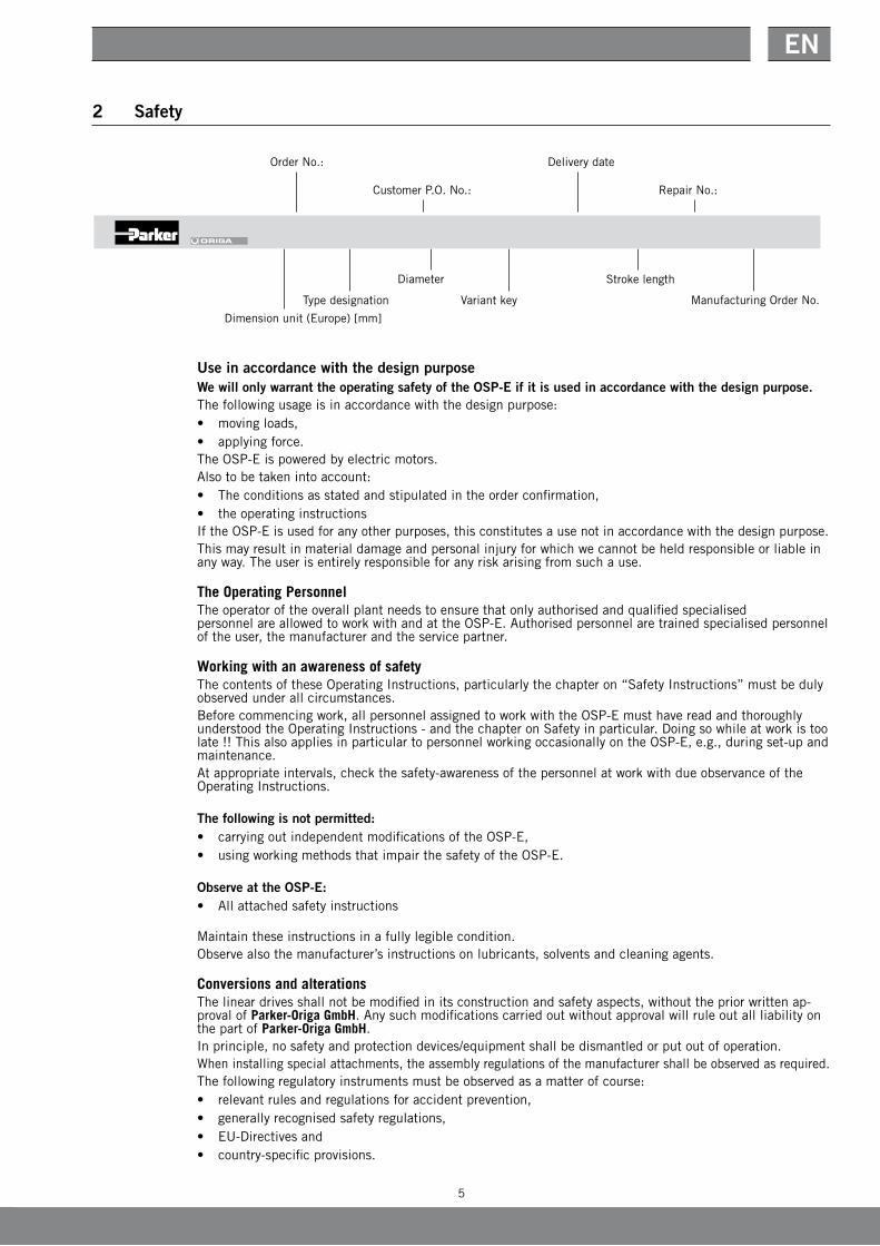
12917/50404HPCA/5.07.2000/R:EU/OSP-E..-50-00000-00400/900006511
Dimension unit (Europe) [mm]
Type designation
Diameter
Variantkey
Strokelength
ManufacturingOrderNo.
OrderNo.:
CustomerP.O.No.:
Delivery date
RepairNo.:

6
Modular electrical linear drives OSP-E
Spare partsTheuseoforiginalsparepartsandaccessoriesauthorisedbythemanufacturerisanimportantaspectforyoursafety.TheuseofotherpartsmaychangethecharacteristicsoftheOSP-E.Weacceptnoliabilityforanyconsequencesresultingfromtheuseofsuchparts.
3 Warranty
WereservetherighttomakealterationstotheseOperatingInstructionsaswellastotechnical detailswithreferencetodataandillustrationsascontainedintheseOperatingInstructions.Parker-Origa GmbH issuesnoqualityanddurabilityguaranteesoranyguaranteesforthesuitabilityforcertainpurposes unless these are expressly agreed in writing.Publicstatements,statementsofqualityoradvertisingarenotstatementsofcharacteristics.Iftheuserwantstomakeaclaimunderthewarranty,heneedstonotifythefaultimmediatelyanddescribeitpreciselyinhisstatementofcomplaint.UndernocircumstancesisParker-Origa GmbH responsiblefordam-agetotheproductitselforforconsequentialdamagecausedbytheproduct,ascausedbyincorrectandfaultyhandlingoftheproduct.InsofarasParker-Origa GmbH isresponsibleforafault, Parker-Origa GmbH may,atitsdiscretion,eitherrepair/modifytheproductorreplacetheitemwithanewone.AllOSP-EareprovidedwithanidentificationplatewithintheframeworkofISO9000,thatis attached to an OSP-E. This identification plate shall not be removed or destroyed in any way.AliabilityofMessrsParker-Origa GmbH –irrespectiveofthelegalreason–existsonlyintheeventofinten-tionalorgrossnegligence,culpableinjurytolife,body,health,intheeventofdeficiencieswithmaliciousintentofdeceptionorfaultstheabsenceofwhichhasbeenexpresslyguaranteed.Furthermore,thecompanyisliabletotheextentstipulatedbytheproductliabilitylawregardingpersonalin-juryormateri-aldamageonobjectsusedprivately.Intheeventofculpableviolationofessentialcontractualobligations,Parker-Origa GmbH isliablealsointhecaseofminornegligence, however,limitedtothedamagethatcouldbeforeseenunderthecontract.Any other claims are ruled out.Nowarrantyshallapplyintheeventofnon-observanceoftheseOperatingInstructions,therelevantlegalprovisionsaswellasfurtherinstructionsofthesupplier.Inparticular,wearenotresponsibleforstoppagescausedbymodificationsbythecustomerorotherpersons.Insuchcases,wechargethenormalrepaircosts.Thesearealsochargedforaninspectionoftheequipmentwherenofaultcanbefoundontheequipment.This regulation also applies during the warranty period.Usershavenorightsregardingthesupplyofpreviousequipmentversionsorregardingtheupgradingofequipmenttothecurrentversion.
4 Transport and Assembly
4.1 TransportThelineardrivesOSP-Earehigh-precisionequipment. Strongandabruptjolts/bumpscandamagethemechanicalsystem oraffectthefunctioning.Inordertoavoiddamageduringtransport, theequipmentisfixedinappropriateprotectivepackaging.
Danger caused by falling load
Incorrect transport and assembly of the OSP-E can:• endangerhumanlife,• resultinmaterialdamage.
Transport of the packaged OSP-E with a crane or a forked-lift truck.• Applyslingingasshown,andpositionthefork-lifttruckasshown.
Transport of the OSP-E with a crane• Applyslingingasshown.
InformationTransport damage and missing parts are to be reported immediately and in writing to the transport company or to Parker-Origa GmbH or to the delivery company.
7
EN
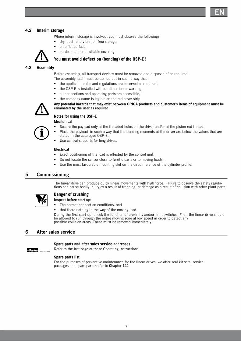
4.2 Interim storageWhereinterimstorageisinvolved,youmustobservethefollowing:• dry,dust-andvibration-freestorage,• onaflatsurface,• outdoorsunderasuitablecovering.
You must avoid deflection (bending) of the OSP-E !
4.3 AssemblyBeforeassembly,alltransportdevicesmustberemovedanddisposedofasrequired.Theassemblyitselfmustbecarriedoutinsuchawaythat• theapplicablerulesandregulationsareobservedasrequired,• theOSP-Eisinstalledwithoutdistortionorwarping,• allconnectionsandoperatingpartsareaccessible,• thecompanynameislegibleontheredcoverstrip.Any potential hazards that may exist between ORIGA products and customer’s items of equipment must be eliminated by the user as required.
Notes for using the OSP-EMechanical• Securethepayloadonlyatthethreadedholesonthedriverand/oratthepistonrodthread.• Placethepayloadinsuchawaythatthebendingmomentsatthedriverarebelowthevaluesthatare
stated in the catalogue OSP-E.• Usecentralsupportsforlongdrives.
Electrical• Exactpositioningoftheloadiseffectedbythecontrolunit.• Donotlocatethesensorclosetoferriticpartsortomovingloads.• Usethemostfavourablemountingslotonthecircumferenceofthecylinderprofile.
5 Commissioning
Thelineardrivecanproducequicklinearmovementswithhighforce.Failuretoobservethesafetyregula-tionscancausebodilyinjuryasaresultoftrapping,ordamageasaresultofcollisionwithotherplantparts.
Danger of crushingInspect before start-up:• Thecorrectconnectionconditions,and• thattherenothinginthewayofthemovingload.Duringthefirststart-up,checkthefunctionofproximityand/orlimitswitches.First,thelineardriveshouldbeallowedtorunthroughtheentiremovingzoneatlowspeedinordertodetectany possible collision areas. These must be removed immediately.
6 After sales service
Spare parts and after sales service addressesRefertothelastpageoftheseOperatingInstructions
Spare parts listForthepurposesofpreventivemaintenanceforthelineardrives,weoffersealkitsets,service packagesandspareparts(refertoChapter 11).
8
Modular electrical linear drives OSP-E
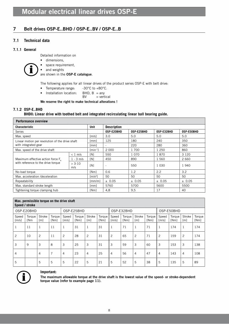
Performance overview
Characteristic Unit DescriptionSeries OSP-E20BHD OSP-E25BHD OSP-E32BHD OSP-E50BHDMax. speed [m/s] 3.0 5.0 5.0 5.0
Linearmotionperrevolutionofthedriveshaftwith integrated gear
[mm] 125 180 240 350
[mm] - 220 280 360
Max.speedofthedriveshaft [min-1] 2 000 1 700 1 250 860
MaximumeffectiveactionforceFA withreferencetothedrivetorque
< 1 m/s [N] 550 1 070 1 870 3 120
1 - 3 m/s [N] 450 890 1 560 2 660
> 3-10 m/s
[N] - 550 1 030 1 940
No-loadtorque [Nm] 0.6 1.2 2.2 3.2
Max. acceleration /deceleration [m/s²] 50 50 50 50
Repeatability [mm/m] ± 0.05 ± 0.05 ± 0.05 ± 0.05
Max.standardstrokelength [mm] 5760 5700 5600 5500
Tighteningtorqueclampinghub [Nm] 4,8 9,5 17 40
7 Belt drives OSP-E..BHD / OSP-E..BV / OSP-E..B
7.1 Technical data
7.1.1 GeneralDetailedinformationon• dimensions,• spacerequirement,• andweightsare shown in the OSP-E catalogue.
ThefollowingappliesforalllineardrivesoftheproductseriesOSP-Ewithbeltdrive:• Temperaturerange: -30°Cto+80°C.• Installationlocation: BHD,B=any
BV =verticalWe reserve the right to make technical alterations !
7.1.2 OSP-E..BHD BHDII: Linear drive with toothed belt and integrated recirculating linear ball bearing guide.
Max. permissible torque on the drive shaftSpeed / stroke
OSP-E20BHD OSP-E25BHD OSP-E32BHD OSP-E50BHD
Speed [m/s]
Torque[Nm
Stroke[m]
Torque[Nm]
Speed [m/s]
Torque[Nm]
Stroke[m]
Torque[Nm]
Speed[m/s]
Torque[Nm]
Stroke[m]
Torque[Nm]
Speed[m/s]
Torque[Nm]
Stroke[m]
Torque[Nm]
1 11 1 11 1 31 1 31 1 71 1 71 1 174 1 174
2 10 2 11 2 28 2 31 2 65 2 71 2 159 2 174
3 9 3 8 3 25 3 31 3 59 3 60 3 153 3 138
4 4 7 4 23 4 25 4 56 4 47 4 143 4 108
5 5 5 5 22 5 21 5 52 5 38 5 135 5 89
Important:The maximum allowable torque at the drive shaft is the lowest value of the speed- or stroke-dependent torque value (refer to example page 11).

9
EN
Performance overview
Characteristic Unit Description
Series OSP-E25BHD OSP-E32BHD OSP-E50BHD
Max. speed [m/s] 10 10 10
Linearmotionperrevolutionofthedriveshaft [mm] 180 240 350
Max.speedofthedriveshaft [min-1] 3 000 2 500 1 700
Maximumeffectiveactionforcewithreferencetothedrivetorque
<1m/s: [N] 1 070 1 870 3 120
1 - 3 m/s [N] 890 1 560 2 660
> 3-10 m/s [N] 550 1 030 1 940
No-loadtorque [Nm] 1.2 2.2 3.2
Max. acceleration /deceleration [m/s²] 40 40 40
Repeatability [mm/m] ± 0.05 ± 0.05 ± 0.05
Max.standardstrokelength [m] 7 7 7
Tighteningtorqueclampinghub [Nm] 9,5 17 40
Max. allowable torque at the drive shaftSpeed / stroke
OSP-E25BHD OSP-E32BHD OSP-E50BHD
Speed[m/s]
Torque[Nm]
Stroke[m]
Torque[Nm]
Speed [m/s]
Torque[Nm]
Stroke[m]
Torque[Nm]
Speed [m/s]
Torque[Nm]
Stroke[m]
Torque[Nm]
1 31 1 31 1 71 1 71 1 174 1 10,0
2 28 2 31 2 65 2 71 2 159 2 10,0
3 25 3 31 3 59 3 60 3 153 3 138
4 23 3 25 4 56 4 47 4 143 4 108
5 22 5 21 5 52 5 38 5 135 5 89
6 21 6 17 6 50 6 32 6 132 6 76
7 19 7 15 7 47 7 28 7 126 7 66
8 18 8 46 8 120
9 17 9 44 9 116
10 16 10 39 10 108
7.1.3 OSP-E..BHD
BHD: Linear drive with toothedbelt and integrated roller guide
Important:The maximum allowable torque at the drive shaft is the lowest value of the speed- or stroke-dependent torque value (refer to example page11).

10
Modular electrical linear drives OSP-E
Max. allowable torque at the drive shaftSpeed / stroke
OSP-E20BHD OSP-E25BHD
Speed .[m/s]
Torque[Nm] Stroke[m] Torque[Nm] Speed [m/s] Torque[Nm] Stroke[m] Torque[Nm]
1 19 1 17 1 36 1 36
2 17 2 10.5 2 30 36
3 15.5 3 30
4 28
5 27
7.1.4 OSP-E..BV Vertical linear drive with with toothed belt and inegrated recirculating linear ball bearing guide
Performance overview
Characteristic Unit Description
Series OSP-E20BHD OSP-E25BHD
Max. speed [m/s] 3.0 5.0
Linearmotionperrevolutionofthedriveshaft [mm] 108 160
Max.speedofthedriveshaft [min-1] 1 700 1 875
MaximumeffectiveactionforceFA with referencetothedrivetorque
<1m/s: [N] 650 1 430
1-3m/s: [N] 890 1 560
>3-5m/s: [N] - 1 050
No-loadtorque [Nm] 0.6 1.2
Max. acceleration /deceleration [m/s²] 20 20
Repeatability [mm/m] ± 0.05 ± 0.05
Max.standardstrokelength [mm] 1 000 1 000
Tighteningtorqueclampinghub [Nm] 4.8 9.5
Recomended permissible mass [kg] 10 20
Important:The maximum allowable torque at the drive shaft is the lowest value of the speed- or stroke-dependent torque value (refer to example page11).

11
EN
7.1.5 OSP-E..B
Linear drive with toothed belt and internal plain bearing guide
Performance overview
Characteristic Unit Description
Series OSP-E25B OSP-E32B OSP-E50B
Max. speed [m/s] 2 3 5
Linearmotionperrevolutionofthedriveshaft [mm] 60 60 100
Max.speedofthedriveshaft [min-1] 2 000 3 000 3 000
MaximumeffectiveactionforceFA with referencetothedrivetorque
<1m/s: [N] 50 150 425
1-2m/s: [N] 50 120 375
>2m/s: [N] - 100 300
Max. acceleration /deceleration [m/s²] 10 10 10
Repeatability [mm/m] ± 0.05 ± 0.05 ± 0.05
Max.standardstrokelength
Bi-Parting version[m]
3.0 5.0 5.0
2 x 1.5 2 x 2.5 2 x 2.5
No-loadtorque [Nm] 0.4 0.5 0.6
Max. allowable torque at the drive shaftSpeed / stroke
OSP-E25B OSP-E32B OSP-E50B
Speed [m/s]
Torque[Nm]
Stroke[m]
Torque[Nm]
Speed [m/s]
Torque[Nm]
Stroke[m]
Torque[Nm]
Speed [m/s]
Torque[Nm]
Stroke[m]
Torque[Nm]
1 0.9 1 0.9 1 2.3 1 2.3 1 10.0 1 10.0
2 0.9 2 0.9 2 2.0 2 2.3 2 9.5 2 10.0
3 0.9 3 1.8 3 2.3 3 9.0 3 9.0
4 2.3 4 8.0 4 7.0
5 1.8 5 7.5 5 6.0
Important:The maximum allowable torque at the drive shaft is the lowest value of the speed- or stroke-dependent torque value.
Example:OSP-E32Bstroke2m,requiresspeed3m/s;FromtableOSP-E..B:Speed3m/smeans1.8Nmandstroke2mmeans2.3Nm.Themaximumtorqueinthisapplicationis1.8Nm.
12
Modular electrical linear drives OSP-E
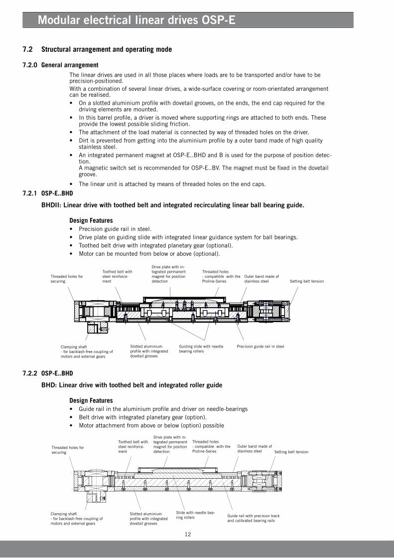
7.2.2 OSP-E..BHD
BHD: Linear drive with toothed belt and integrated roller guide
Design Features• Guiderailinthealuminiumprofileanddriveronneedle-bearings• Beltdrivewithintegratedplanetarygear(option).• Motorattachmentfromaboveorbelow(option)possible
Threadedholesforsecuring
Outerbandmadeofstainless steel
Drive plate with in-tegrated permanent magnetforpositiondetection
Slotted aluminium profile with integrated dovetail grooves
Threaded holes - compatible with the Proline-Series
Slide with needle bea-ring rollers Guiderailwithprecisiontrack
and calibrated bearing rails
Toothed belt with steelreinforce-ment
Clampingshaft-forbacklash-freecouplingofmotors and external gears
Setting belt tension
7.2 Structural arrangement and operating mode
7.2.0 General arrangementThe linear drives are used in all those places where loads are to be transported and/or have to be precision-positioned.Withacombinationofseverallineardrives,awide-surfacecoveringorroom-orientatedarrangementcan be realised.• Onaslottedaluminiumprofilewithdovetailgrooves,ontheends,theendcaprequiredforthe
driving elements are mounted.• Inthisbarrelprofile,adriverismovedwheresupportingringsareattachedtobothends.These
providethelowestpossibleslidingfriction.• Theattachmentoftheloadmaterialisconnectedbywayofthreadedholesonthedriver.• Dirtispreventedfromgettingintothealuminiumprofilebyaouterbandmadeofhighquality
stainless steel.• AnintegratedpermanentmagnetatOSP-E..BHDandBisusedforthepurposeofpositiondetec-
tion. AmagneticswitchsetisrecommendedforOSP-E..BV.Themagnetmustbefixedinthedovetailgroove.
• Thelinearunitisattachedbymeansofthreadedholesontheendcaps.
7.2.1 OSP-E..BHD
BHDII: Linear drive with toothed belt and integrated recirculating linear ball bearing guide.
Design Features• Precisionguiderailinsteel.• Driveplateonguidingslidewithintegratedlinearguidancesystemforballbearings.• Toothedbeltdrivewithintegratedplanetarygear(optional).• Motorcanbemountedfrombeloworabove(optional).
Threadedholesforsecuring
Outerbandmadeofstainless steel
Drive plate with in-tegrated permanent magnetforpositiondetection
Slotted aluminium profile with integrated dovetail grooves
Threaded holes - compatible with the Proline-Series
Guiding slide with needle bearing rollers
Toothed belt with steelreinforce-ment
Clampingshaft-forbacklash-freecouplingofmotors and external gears
Setting belt tension
Precision guide rail in steel
13
EN
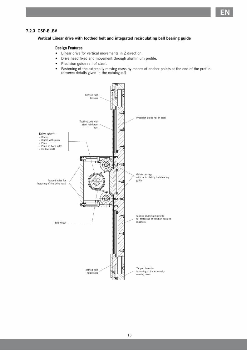
7.2.3 OSP-E..BV
Vertical Linear drive with toothed belt and integrated recirculating ball bearing guide
Design Features• LineardriveforverticalmovementsinZdirection.• Driveheadfixedandmovementthroughaluminiumprofile.• Precisionguiderailofsteel.• Fasteningoftheexternallymovingmassbymeansofanchorpointsattheendoftheprofile.
(observe details given in the catalogue!)
Tappedholesforfasteningofthedrivehead
Belt wheel
Toothed beltFixedside
Driveshaft:- Clamp- Clamp with plain- Plain- Plain on both sides- Hollowshaft
Toothed belt with steelreinforce-
ment
Setting belt tension
Precision guide rail in steel
Guide carriage with recirculating ball-bearing guide
Slotted aluminium profileforfasteningofpositionsensingmagnets
Tappedholesforfasteningoftheexternallymoving mass
14
Modular electrical linear drives OSP-E
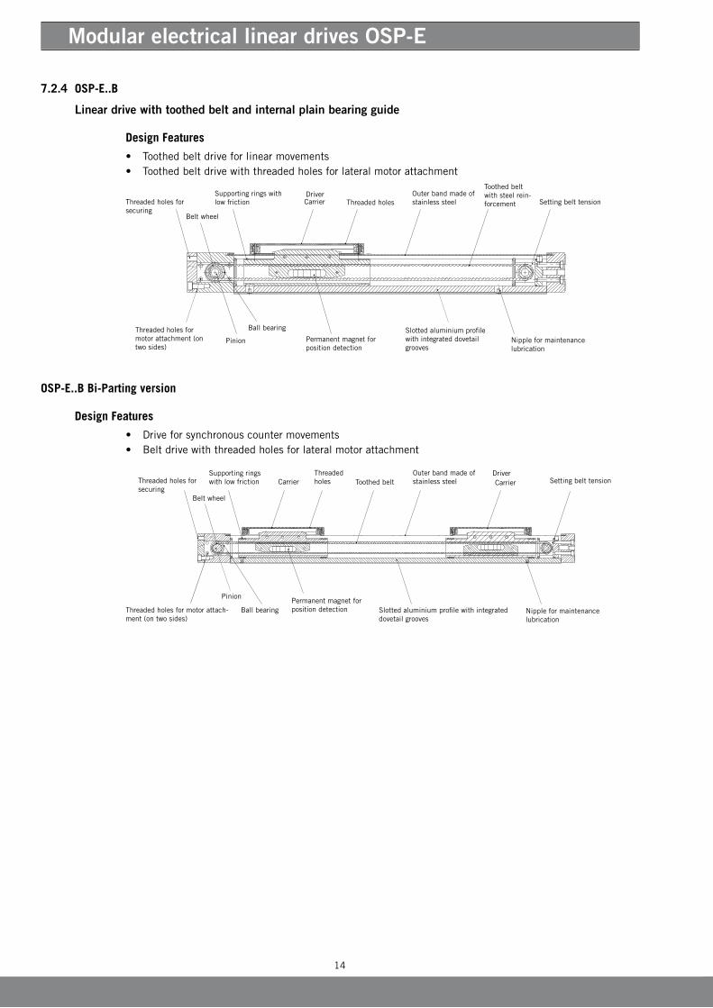
OSP-E..B Bi-Parting version
Design Features
• Driveforsynchronouscountermovements• Beltdrivewiththreadedholesforlateralmotorattachment
7.2.4 OSP-E..B
Linear drive with toothed belt and internal plain bearing guide
Design Features
• Toothedbeltdriveforlinearmovements• Toothedbeltdrivewiththreadedholesforlateralmotorattachment
Threadedholesforsecuring
Outerbandmadeofstainless steel
Belt wheel
Supporting rings with lowfriction Threaded holes
Nippleformaintenancelubrication
Carrier
Permanentmagnetforposition detection
Slotted aluminium profile with integrated dovetail grooves
Toothed belt with steel rein-forcement
Ball bearing
Pinion
Threadedholesformotor attachment (on two sides)
Setting belt tension Driver
Threadedholesforsecuring
Ball bearing
Outerbandmadeofstainless steel Carrier
Slotted aluminium profile with integrated dovetail grooves
Permanentmagnetforposition detection
Toothed belt
Nippleformaintenancelubrication
Threaded holes
Supporting rings withlowfriction Setting belt tension
Threadedholesformotorattach-ment (on two sides)
Belt wheel
Carrier
Pinion
Driver

15
EN
7.3 Maintenance / repair
AttentionMaintenance and repair work shall only be carried out by specially trained and instructed persons !
AttentionThe machine or the working zone must be cordoned off for safety purposes as required !
7.3.1 CleaningThelineardrivemustbekeptfreefromdirtparticlesatalltimes,particularlythesurfacebetweentheouterband and the aluminium profile and/or the wipers at the carrier.Forcleaning,useonlynonaggressivecleansersandlint-freecloths.
Attention After every cleaning operation, the corresponding parts must be lubricated as required.
7.3.2 LubricationTherollerguidesandshaftbearingsarelubricatedforlife.Werecommendaninspectionofthelineardriveaftermax.3000kmoranoperatingperiodof12months,depending on the application.Thefollowingaspectsmustbetakenintoaccount:• Load• Speed• Temperature• Surroundingconditionofthelineardrives.
Visual inspection for lubricating grease:• Makesurethattheouterbandhasathinlubricatingfilmonbothsides.• Makesurethattheguiderail(OSP-E..BHD)iscoveredwithathinlubricatingfilmasrequired.Forthis
purpose,theclampingpiecesfortheouterbandmustbeloosenedsothatthiscanbeliftedupeasily.
Lubrication of the running surfaces in the tube (OSP-E..B):Onthedownwardfacingsideofthelineardrive,therearetwogreasenipplesforlubricatingtherunningsurfaces.Inordertoperformlubricationwithagreasegun,thedrivermustbemovedintoitscorres-pond-inggreasingposition(ifnecessary,inchingmovementinthedirectionofthemechanicallimitpositionofthedrive).Refertothetablefortheclearancevalues.
Type Dimension a [mm] Dimension b [mm]
OSP-E25B 64 71
OSP-E32B 73 79
OSP-E50B 98 103
Lubricant
• Parker-Origa-grease2 (HO-Grease2IdentNo.:#15071Tube45gr)
(Drive side)
(Reverse guide side )Lubricating nipple
Lubricating nipple
a
b
16
Modular electrical linear drives OSP-E
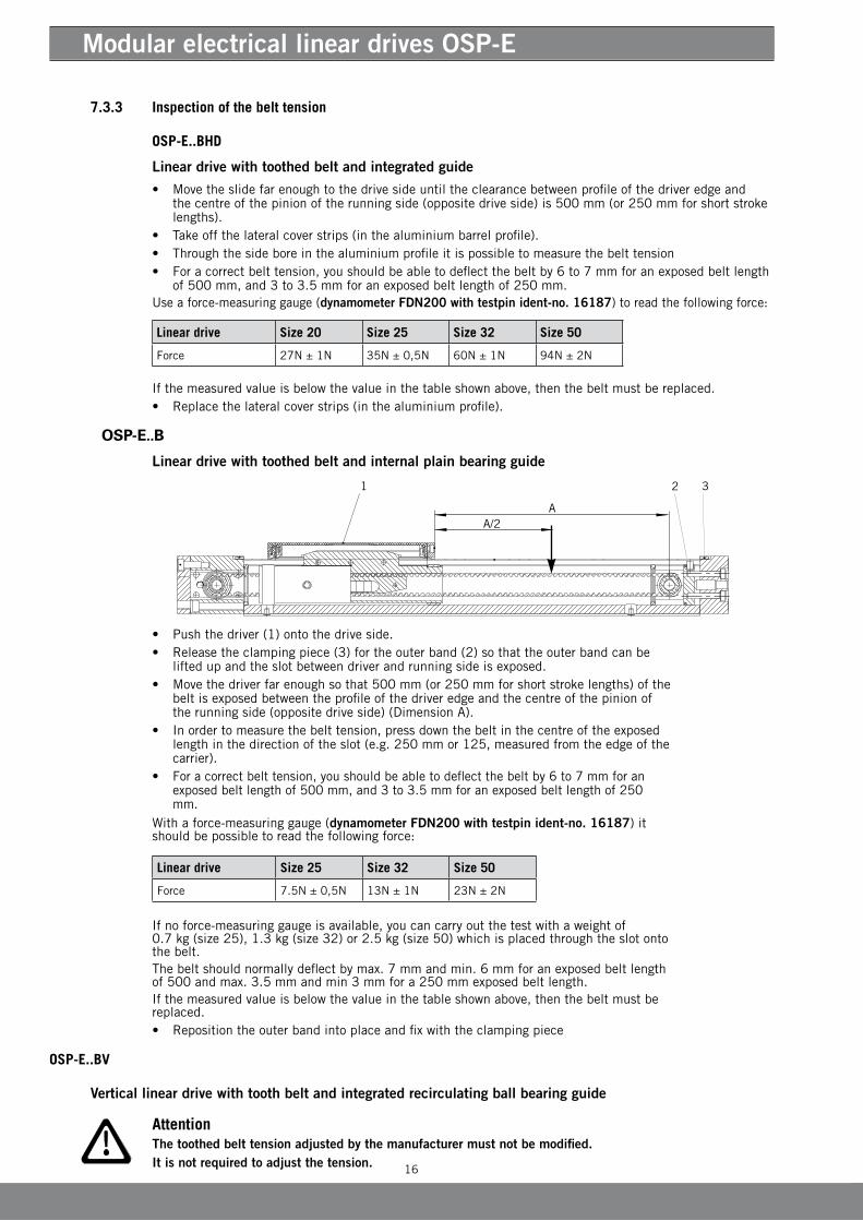
7.3.3 Inspection of the belt tension
OSP-E..BHD
Linear drive with toothed belt and integrated guide
• Movetheslidefarenoughtothedrivesideuntiltheclearancebetweenprofileofthedriveredgeandthecentreofthepinionoftherunningside(oppositedriveside)is500mm(or250mmforshortstrokelengths).
• Takeoffthelateralcoverstrips(inthealuminiumbarrelprofile).• Throughthesideboreinthealuminiumprofileitispossibletomeasurethebelttension• Foracorrectbelttension,youshouldbeabletodeflectthebeltby6to7mmforanexposedbeltlength
of500mm,and3to3.5mmforanexposedbeltlengthof250mm.Useaforce-measuringgauge (dynamometer FDN200 with testpin ident-no. 16187)toreadthefollowingforce:
Ifthemeasuredvalueisbelowthevalueinthetableshownabove,thenthebeltmustbereplaced.• Replacethelateralcoverstrips(inthealuminiumprofile).
OSP-E..B
Linear drive with toothed belt and internal plain bearing guide
Withaforce-measuringgauge(dynamometer FDN200 with testpin ident-no. 16187) it shouldbepossibletoreadthefollowingforce:
Linear drive Size 25 Size 32 Size 50
Force 7.5N±0,5N 13N±1N 23N±2N
Ifnoforce-measuringgaugeisavailable,youcancarryoutthetestwithaweightof 0.7kg(size25),1.3kg(size32)or2.5kg(size50)whichisplacedthroughtheslotontothe belt.Thebeltshouldnormallydeflectbymax.7mmandmin.6mmforanexposedbeltlengthof500andmax.3.5mmandmin3mmfora250mmexposedbeltlength.Ifthemeasuredvalueisbelowthevalueinthetableshownabove,thenthebeltmustbereplaced.• Repositiontheouterbandintoplaceandfixwiththeclampingpiece
OSP-E..BV
Vertical linear drive with tooth belt and integrated recirculating ball bearing guide
Attention The toothed belt tension adjusted by the manufacturer must not be modified.It is not required to adjust the tension.
• Pushthedriver(1)ontothedriveside.• Releasetheclampingpiece(3)fortheouterband(2)sothattheouterbandcanbe
liftedupandtheslotbetweendriverandrunningsideisexposed.• Movethedriverfarenoughsothat500mm(or250mmforshortstrokelengths)ofthe
beltisexposedbetweentheprofileofthedriveredgeandthecentreofthepinionofthe running side (opposite drive side) (Dimension A).
• Inordertomeasurethebelttension,pressdownthebeltinthecentreoftheexposedlengthinthedirectionoftheslot(e.g.250mmor125,measuredfromtheedgeofthecarrier).
• Foracorrectbelttension,youshouldbeabletodeflectthebeltby6to7mmforan exposedbeltlengthof500mm,and3to3.5mmforanexposedbeltlengthof250mm.
Linear drive Size 20 Size 25 Size 32 Size 50
Force 27N±1N 35N±0,5N 60N±1N 94N±2N
17
EN
5
4
32
1
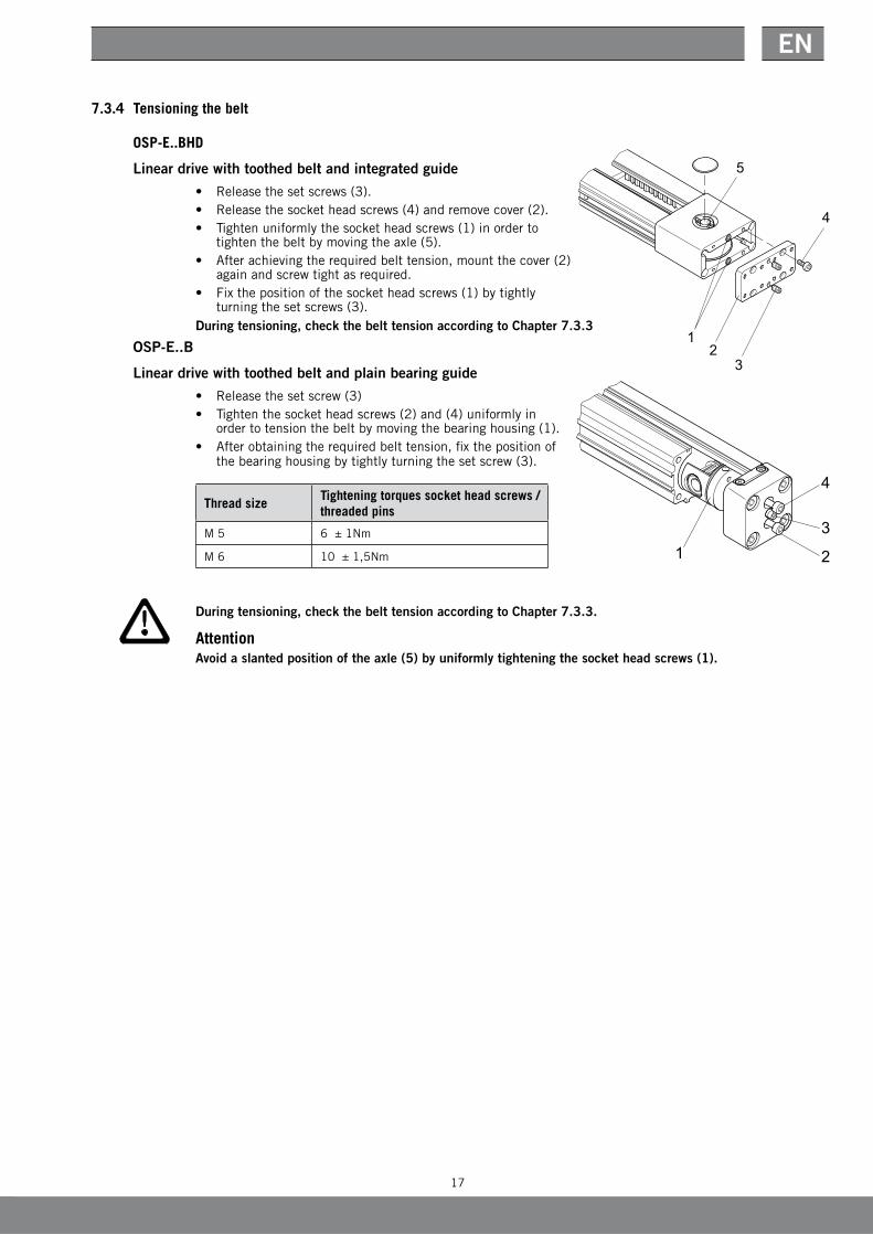
7.3.4 Tensioning the belt
OSP-E..BHD
Linear drive with toothed belt and integrated guide
• Releasethesetscrews(3).• Releasethesocketheadscrews(4)andremovecover(2).• Tightenuniformlythesocketheadscrews(1)inorderto
tighten the belt by moving the axle (5).• Afterachievingtherequiredbelttension,mountthecover(2)
againandscrewtightasrequired.• Fixthepositionofthesocketheadscrews(1)bytightly
turning the set screws (3).During tensioning, check the belt tension according to Chapter 7.3.3
OSP-E..B
Linear drive with toothed belt and plain bearing guide
• Releasethesetscrew(3)• Tightenthesocketheadscrews(2)and(4)uniformlyin
order to tension the belt by moving the bearing housing (1).• Afterobtainingtherequiredbelttension,fixthepositionof
the bearing housing by tightly turning the set screw (3).
Thread sizeTightening torques socket head screws / threaded pins
M 5 6±1Nm
M 6 10±1,5Nm
During tensioning, check the belt tension according to Chapter 7.3.3.
AttentionAvoid a slanted position of the axle (5) by uniformly tightening the socket head screws (1).
1 2
3
4
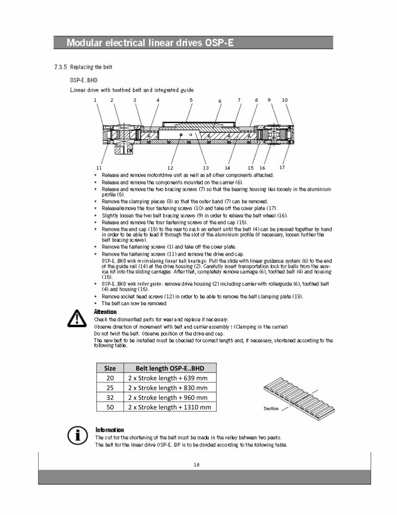
Size Belt length OSP-E..BHD
20 2 x Stroke length + 639 mm
25 2 x Stroke length + 830 mm
32 2 x Stroke length + 960 mm
50 2 x Stroke length + 1310 mm

Size Clearance Dimension A
20 185 mm
25 218 mm
32 262 mm
50 347 mm
Sorting of tooth belt, bi-parting
Size Teeth
Drive side Reverse Guide side
20 3 4
25 2 1
32 4 3
50 6 5
20
Modular electrical linear drives OSP-E
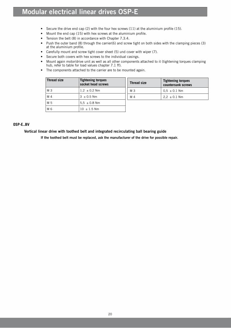
• Securethedriveendcap(2)withthefourhexscrews(11)atthealuminiumprofile(15).• Mounttheendcap(15)withhexscrewsatthealuminiumprofile.• Tensionthebelt(8)inaccordancewithChapter7.3.4.• Push the outer band (8) through the carrier(6) and screw tight on both sides with the clamping pieces (3)
at the aluminium profile.• Carefullymountandscrewtightcoversheet(5)undcoverwithwiper(7).• Securebothcoverswithhexscrewstotheindividualcasings.• Mountagainmotor/driveunitaswellasallothercomponentsattachedtoit(tighteningtorquesclamping
hub,refertotableforloadvalueschapter 7.1ff).• Thecomponentsattachedtothecarrieraretobemountedagain.
OSP-E..BV
Vertical linear drive with toothed belt and integrated recirculating ball bearing guide
If the toothed belt must be replaced, ask the manufacturer of the drive for possible repair.
Thread sizeTightening torques countersunk screws
M 3 0,5±0.1Nm
M 4 2,2±0.1Nm
Thread size Tightening torques socket head screws
M 3 1.2±0.2Nm
M 4 3±0.5Nm
M 5 5,5±0.8Nm
M 6 10±1.5Nm
21
EN
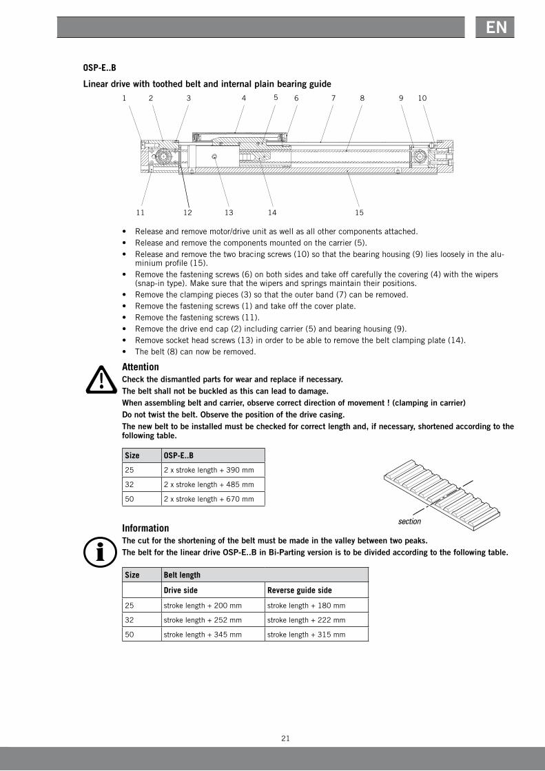
OSP-E..B
Linear drive with toothed belt and internal plain bearing guide
• Releaseandremovemotor/driveunitaswellasallothercomponentsattached.• Releaseandremovethecomponentsmountedonthecarrier(5).• Releaseandremovethetwobracingscrews(10)sothatthebearinghousing(9)lieslooselyinthealu-
minium profile (15).• Removethefasteningscrews(6)onbothsidesandtakeoffcarefullythecovering(4)withthewipers
(snap-intype).Makesurethatthewipersandspringsmaintaintheirpositions.• Removetheclampingpieces(3)sothattheouterband(7)canberemoved.• Removethefasteningscrews(1)andtakeoffthecoverplate.• Removethefasteningscrews(11).• Removethedriveendcap(2)includingcarrier(5)andbearinghousing(9).• Removesocketheadscrews(13)inordertobeabletoremovethebeltclampingplate(14).• Thebelt(8)cannowberemoved.
1 2 3 4 6 7 8 10
11
95
13 14 1512
AttentionCheck the dismantled parts for wear and replace if necessary.The belt shall not be buckled as this can lead to damage.When assembling belt and carrier, observe correct direction of movement ! (clamping in carrier)Do not twist the belt. Observe the position of the drive casing.The new belt to be installed must be checked for correct length and, if necessary, shortened according to the following table.
Size OSP-E..B
25 2xstrokelength+390mm
32 2xstrokelength+485mm
50 2xstrokelength+670mm
InformationThe cut for the shortening of the belt must be made in the valley between two peaks.The belt for the linear drive OSP-E..B in Bi-Parting version is to be divided according to the following table.
Size Belt length
Drive side Reverse guide side
25 strokelength+200mm strokelength+180mm
32 strokelength+252mm strokelength+222mm
50 strokelength+345mm strokelength+315mm
section

22
Modular electrical linear drives OSP-E
A Aorderstroke
OSP-E..B
Size clearance dimension A
25 125 mm
32 150 mm
50 200 mm
InformationAfter assembly, the clearance dimension (A) on both sides must be checked and, if required, corrected by shifting the belt.
Mounting of the belt
• Placebelt(8)aroundthedrivebeltwheel.• MovetheX-ringsoverthebelt(8)asthesecannotbemountedafter.• Movethebeltend,whichisnottobeclamped,correctlypositionedthroughthecarrier(5)andaround
thesecondbeltwheel(donotforgettheX-rings).• Putinthebeltclampingplate(14)intothecarrier(5).
OSP-E..B• Placeinthebelt(8)intothebeltclampingplate(14)onbothsidesinsuchawaythatnotoothremains
free(beltendsmeetinthemiddle).
OSP-E..B Bi-Parting version• Placeinthebelt(8)intothebeltclampingplate(14)onbothsidesinsuchawaythatthemiddletooth
oftheclampingplateremainsfree.• Withthescrews(13)securethebeltclampingplatetothecarrier(5)(andsecurewiththreadlock).• Movethebearinghousing(9)andthecarrier(5)intothealuminiumprofile(15)..
AttentionDo not twist the belt. Observe the position of the drive casing (2). When assembling belt and carrier, observe correct direction of movement ! (clamping in carrier
• Withthehelpofthesupportingringsandthesliderails,bringthecarrier(5)intoitscorrectposition.• Securethedriveendcap(2)withthefourhexscrews(11)atthealuminiumprofile(15).• Securethecoverplatewiththetwohexscrews(1)atthedriveendcap(2).
1 2 3 4 6 7 8 10
11
95
13 14 1512

23
EN
• Tensionthebelt(8)inaccordancewithChapter7.3.4.• Pushtheouterband(7)throughthecarrierandscrewtightonbothsideswiththeclampingpiecesat
the aluminium profile.• Withgreatcare,mountthecovering(4)withthewipers(snap-intype)andscrewtightasrequired.Make
sure that the wipers and springs maintain their positions.• Motor/driveunitandallattachedcomponentsaretobemountedagain.• Thecomponentsattachedtothecarrieraretobemountedagain.
Thread sizeTightening torques socket head screws
M 3 1.2±0.2Nm
M 4 3±0.5Nm
M 5 5.5±0.8Nm
M 6 10±1.5Nm
Thread sizeTightening torques countersunk screws
M 3 0.5±0.1Nm
M 4 2.2±0.1Nm
7.3.6 Replace wiper / outer bandIfthewipersareworn,thesemustbereplacedaccordingly.
• Loosenandremovethecomponentsmountedonthecarrier.• Removethefasteningscrews(2)onbothsidesandtakeoffcarefullythecovering(1)withthewipers
(snap-intype).Makesurethatthewipersandspringsmaintaintheirpositions.• Thenewwiperscannowbemountedagain.If the outer band has visible damage so that dirt can get into the aluminium profile, it must be replaced im-mediately.• Dismantlewipers.• Removeclampingpieces(3)sothattheouterband(4)canberemovedandreplaced
Thread size Tightening torques countersunk screws
M 3 0,5±0.1Nm
M 4 2,2±0.1Nm
7.3.7 Replace bearing strips / bearing ringsThe clearance between the bearing strips (2) and the aluminium profile should be maximum 0.2 mm. Any excessofthisvaluemeansthatthebearingstripsmustbereplaced.
• DismantlethedriveinaccordancewithChapter7.3.4(donotdismantlethebelt!)• Removebothbearingstrips(2)andreplacewithnewbearingstripsofthesamecolour.• Inspectthesupportingrings(1)forwearand,ifnecessary,replacewithnewsupportingringsofthesame
thickness.
1 2 4 33
24
Modular electrical linear drives OSP-E
7.3.8 Check the bearingsIfthereisincreasednoisedevelopmentwiththemovementofthelineardrives,thebearingsmustbein-spectedforwear.Suchaninspectionshouldbecarriedoutevery3000kmrunningperformanceorevery12months.• Loosenandremovemotor/driveunitaswellasallothercomponentsattached.• Inspectbeltandguidesforpossibledirt(loosenouterbandandliftupforvisualinspection).• Turndriveshaftbyhandinbothdirections.Thisshouldbepossiblewithoutjoltsandwitheasymove-
ment.Inordertochecktherunningbehaviourinabetterway,ifnecessary,mountcouplingondriveaxle.Observetorqueforno-loadrun!(seepage8/10)
• Ifthisisnotpossible,thelineardrivemustbedismantledandthedamagedbearingreplaced.
8 Spindle drives OSP-E..SB / OSP-E..ST / OSP-E..SBR / OSP-E..STR
8.1 Technical data
8.1.1 GeneralDetailedinformationon• dimensions,• spacerequirement,• weightsare shown in the OSP-E catalogue.
ForalllineardrivesoftheproductseriesOSP-E,thefollowingapplies:
Temperature ranges: • OSP-E..SB -20°Cto+80°C.• OSP-E..ST -20°Cto+70°C.• OSP-E..SBR -20°Cto+80°C.• OSP-E..STR -20°Cto+70°C.
Installationlocation:nospecificrequirements
We reserve the right to make technical alterations !

25
EN
Performance overview
Characteristic Unit Description
Series OSP-E25SB OSP-E32SB OSP-E50SB
Pitch [mm] 5 5 10 5 10 25 50
Max. speed [m/s] 0.25 0.25 0.5 0.25 0.5 1.25 2.5
Linearmotionperrevolutionofthedriveshaft [mm] 5 5 10 5 10 25 50
Max.speedofthedriveshaft [min-1] 3 000 3 000 3 000
MaximumeffectiveactionforceFA
withreferencetothedrivetorque
[N] 250 600 1 500
[Nm] 0.35 0.75 1.3 1.7 3.1 7.3 14.6
No-loadtorque [Nm] 0.2 0.2 0.3 0.3 0.4 0.5 0.6
Max.allowabledrivetorqueatthedriveshaft [Nm] 0.6 1.5 2.8 4.2 7.5 20 20
Repeatability [mm/m] ± 0.05 ± 0.05 ± 0.05
Max.standardstrokelength [m] 1.1 2.0 3.2
8.1.2 OSP-E..SB
Linear drive with ball screw drive and internal plain bearing guide
Performance overview
Characteristic Unit Description
Series OSP-E25ST OSP-E32ST OSP-E50ST
Pitch [mm] 4 4 6
Max. speed [m/s] 0.1 0.1 0.15
Linearmotionperrevolutionofthedriveshaft [mm] 4 4 6
Max.speedofthedriveshaft [min-1] 1 500 1 500 1 500
MaximumeffectiveactionforceFA
withreferencetothedrivetorque
[N] 600 1 300 2 500
[Nm] 1.35 3.2 8.8
No-loadtorque [Nm] 0.3 0.4 0.5
Max.allowabledrivetorqueatthedriveshaft [Nm] 1.55 4.0 9.4
Self-lockingFL [N] 600 1300 2500
Repeatability [mm/m] ± 0.5 ± 0.5 ± 0.5
Max.standardstrokelength [m] 1.1 2.0 2.5
8.1.3 OSP-E..ST
Linear drive with trapezoidal screw drive and internal plain bearing guide

26
Modular electrical linear drives OSP-E
8.1.4 OSP-E..SBR
Linear drive with ball screw drive, internal plain bearing guide and piston rod
8.1.5 OSP-E..STR
Linear drive with trapezoidal screw drive, internal plain bearing guide and piston rod
Performance overview
Characteristic Unit
Series OSP-E25STR OSP-E32STR OSP-E50STR
Pitch [mm] 3 4 5
Max. speed [m/s] 0.075 0.1 0.125
Linearmotionperrevolutionofthedriveshaft [mm] 3 4 5
Max.speedofthedriveshaft [min-1] 1 500 1 500 1 500
MaximumeffectiveactionforceFAwithreferencetothedrivetorque
[N] 800 1 600 3 300
[Nm] 1.35 3.4 9.25
No-loadtorque [Nm] 0.3 0.4 0.5
Max.allowabledrivetorqueatthedriveshaft [Nm] 1.7 4.4 12
Self-lockingFl [N] 800 1600 3300
Repeatability [mm/m] ± 0.5 ± 0.5 ± 0.5
Max.standardstrokelength [m] 0.5 0.5 0.5
Performance overview
Characteristic Unit
Series OSP-E25SBR OSP-E32SBR OSP-E50SBR
Pitch [mm] 5 5 10 5 10 25
Max. speed [m/s] 0.25 0.25 0.5 0.25 0.5 1.25
Linearmotionperrevolutionofthedriveshaft [mm] 5 5 10 5 10 25
Max.speedofthedriveshaft [min-1] 3 000 3 000 3 000
MaximumeffectiveactionforceFA
withreferencetothedrivetorque
[N] 250 550 1090 750 990 1680
[Nm] 0.3 0.65 2.6 0.9 2.4 10
No-loadtorque [Nm] 0.2 0.2 0.3 0.3 0.4 0.5
Max.allowabledrivetorqueatthedriveshaft [Nm] 0.6 1.5 2.8 4.2 7.5 20
Repeatability [mm/m] ± 0.05 ± 0.05 ± 0.05
Max.standardstrokelength [mm] 500 500 500

27
EN
8.2 Structural arrangement and operating mode
8.2.1 General arrangementThe linear drives are used in all those places where loads are to be transported and/or have to be precision-positioned.Withacombinationofseverallineardrives,awide-surfacecoveringorroom-orientatedarrangementcanberealised.• Onaslottedaluminiumprofilewithdovetailgrooves,ontheends,theendcaprequiredforthedriving
elements are mounted.• Inthisbarrelprofile,acarrierismovedwheresupportingringsareattachedtobothends.Theseprovide
thelowestpossibleslidingfriction.• Theattachmentoftheloadmaterialisconnectedbywayofthreadedholesatthecarrier.• Dirtispreventedfromgettingintothealuminiumprofilebyanouterbandmadeofhighqualitystainless
steel.• Anintegratedpermanentmagnetisusedforthepurposeofpositiondetection.• Onthesideofthedriveshaftthereareendcapscrewswithinternalthreadsforsecuringthecoupling
housingandtheflangeplate.
8.2.2 OSP-E..SB
Linear drive with ball screw drive, internal plain bearing guide and piston rod
Design Features• Ballscrewdrive• internalplainbearingguide
8.2.3 OSP-E..ST
Linear drive with trapezoidal screw drive, internal plain bearing guide and piston rod
Design Features• Trapezoidalthreaddrive• selflocking
Two-row slanted ball bearing
DriveshaftOuterbandmadeofstainless steel
Slotted aluminium profile with integrated dovetail grooves
Permanentmagnetforposition detection
Threaded holes
Supporting rings withlowfrictionCarrier
Threaded spindle
Ball nut
Covering
Plastic nut Driveshaft
Outerbandmadeofstainless steel Carrier
Slotted aluminium profile with integrated dovetail grooves
Permanentmagnetforposition detection
Threaded holes
Supporting rings withlowfriction
Trapezoidalthreadedspindle
Two-row slanted ball bearing
28
Modular electrical linear drives OSP-E
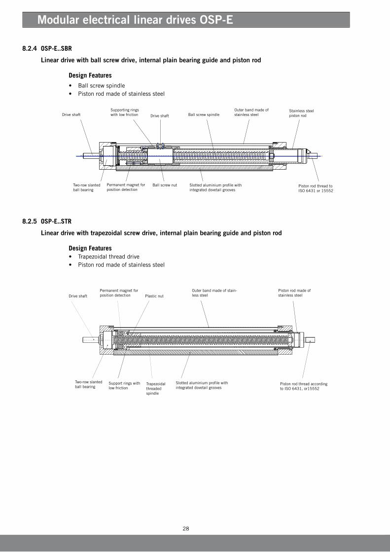
8.2.4 OSP-E..SBR
Linear drive with ball screw drive, internal plain bearing guide and piston rod
Design Features
• Ballscrewspindle• Pistonrodmadeofstainlesssteel
8.2.5 OSP-E..STR
Linear drive with trapezoidal screw drive, internal plain bearing guide and piston rod
Design Features• Trapezoidalthreaddrive• Pistonrodmadeofstainlesssteel
Pistonrodmadeofstainless steel Driveshaft
Outerbandmadeofstain-less steel Plastic nut
Slotted aluminium profile with integrated dovetail grooves
Permanentmagnetforposition detection
Support rings with lowfriction
Trapezoidalthreaded spindle
Piston rod thread according toISO6431,or15552
Two-row slanted ball bearing
Stainless steel piston rodDriveshaft
Slotted aluminium profile with integrated dovetail grooves
Permanentmagnetforposition detection
Supporting rings withlowfriction
Piston rod thread to ISO 6431 or 15552
Two-row slanted ball bearing
Ball screw spindle
Ball screw nut
DriveshaftOuterbandmadeofstainless steel

29
EN
Thread sizeTightening torques countersunk screws
M 3 0,5±0,1Nm
M 4 2,2±0,1Nm
8.3 Maintenance / repair
AttentionMaintenance and repair work shall only be carried out by specially trained and instructed persons !The machine or the working zone must be cordoned off for safety purposes as required !
8.3.1 CleaningThelineardrivemustbekeptfreefromdirtparticlesatalltimes,particularlythesurfacebetweentheouterband and the aluminium profile and/or the wipers at the carrier.Forcleaning,useonlynonaggressivecleansersandlint-freecloths.
AttentionAfter every cleaning operation, the corresponding parts must be lubricated as required.
8.3.2 LubricationTheshaftbearingshavelife-longlubrication.Thefollowingaspectsofthelineardrivesmustbetakenintoaccount:• Load• Speed• Temperature• Surroundingcondition
Lubricant for trapezoidal and ball screw spindle as well as cylinder tube• Parker-Origa-grease2(HO-Grease2IdentNo.:#15071Tube45gr)
Inspection interval for linear drive OSP-E..SB and OSP-E..SBRCarryoutavisualinspectionafteranoperatingperiodofmax.3000kmor12months.
Inspection interval for linear drive OSP-E..ST and OSP-E..STRCarryoutavisualinspectionafteranoperatingperiodofmax.300kmor24months.
Visual inspection for lubricating grease• Makesurethattheouterband/pistonrodhasalwaysathinlubricatingfilmonbothsides.• Makesurethatthespindlesarecoveredwithathinlubricatingfilm.Forthispurpose,theclamping
piecesfortheouterbandmustbeloosenedsothatthiscanbeliftedupeasily.
Lubricating the drive OSP-E..SB and OSP-E..ST• Pushthecarrier(1)intothecentralposition.• Loosenclampingpieces(2)andliftuptheouterband(3).• Placealineofgreaseonthethreadedspindleandtheinsideofthetube.• Pushthedriverbackwardandforwardafewtimesbyhandtoovertheentireguidelength.• Tightlyclamptheouterbandagain.

30
Modular electrical linear drives OSP-E
Lubricating the spindle of linear drive OSP-E..SBR and OSP-E..STR• Removethemotor/driveunitfromthedriveshaft(1).• Movethepistonrod(29)byhandintotheextendedposition.• Releasethecountersunkscrews(4)andclampingpiece(5).Liftthecoverband(14).• Dispenseacontinuousstringofgreaseontothethreadedspindle(13)andtheinsideofthetube(22)).• Movethepistonrod(29)byhandseveraltimesthroughthecompletestroke.• Repositionthecoverband(14).Puttheclampingpiece(5)backintoplaceandinsertthecounter-sunk
screws(4),tighteningthemtotheappropriatetorque.• Afterthelubricationthemotor/driveunitisreadytobemountedagain.
Thread sizeTightening torques countersunk screws
M 3 0,5±0,1Nm
M 4 2,2±0,1Nm
8.3.3 Check axle backlash of drive spindles
Inspection of the axle backlash of the drive spindles• Theaxlebacklashofthedrive spindles is determined by axially moving the carrier (1)
(OSP-E..SB / OSP-E..ST) and/or the piston rod (2) (OSP-E..SBR / OSP-E..STR) at machine standstill.The determined clearance shouldnotexceed:• OSP-E..S 0.2 mm• OSP-E..ST 0.5 mm• OSP-E..SBR 0.2 mm• OSP-E..STR 0.5 mm
AttentionIf the allowable backlash clearance is exceeded, the spindle nuts and/or the spindles must be replaced.
8.3.4 Replacing the spindle nut / spindle
OSP-E..SB
Linear drive with ball screw drive and internal plain bearing guide
InformationThe exchange of the ball screw spindle requires perfect coordination. The ball screw nut must be adjusted precisely in order to avoid premature wear due to faulty installation. The spindle must only be repaired by Parker-Origa GmbH or separately instructed personnel.
31
EN
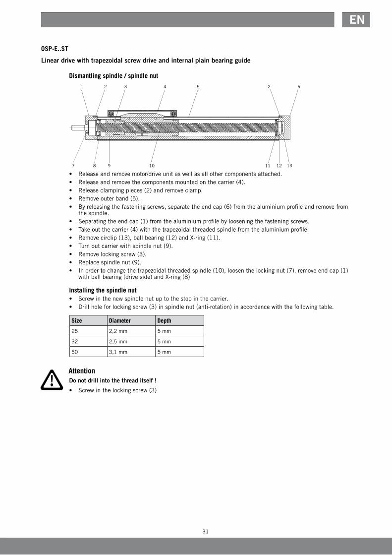
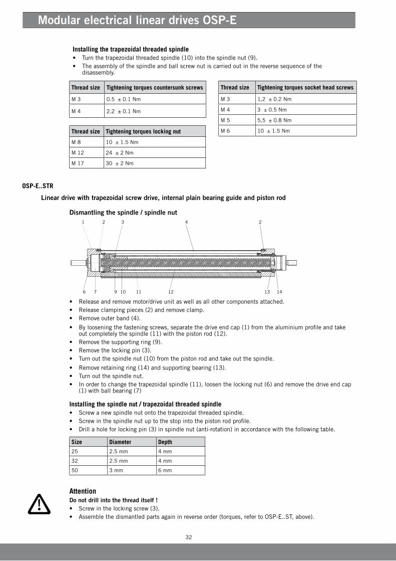
OSP-E..ST
Linear drive with trapezoidal screw drive and internal plain bearing guide
Dismantling spindle / spindle nut
• Releaseandremovemotor/driveunitaswellasallothercomponentsattached.• Releaseandremovethecomponentsmountedonthecarrier(4).• Releaseclampingpieces(2)andremoveclamp.• Removeouterband(5).• Byreleasingthefasteningscrews,separatetheendcap(6)fromthealuminiumprofileandremovefrom
the spindle.• Separatingtheendcap(1)fromthealuminiumprofilebylooseningthefasteningscrews.• Takeoutthecarrier(4)withthetrapezoidalthreadedspindlefromthealuminiumprofile.• Removecirclip(13),ballbearing(12)andX-ring(11).• Turnoutcarrierwithspindlenut(9).• Removelockingscrew(3).• Replacespindlenut(9).• Inordertochangethetrapezoidalthreadedspindle(10),loosenthelockingnut(7),removeendcap(1)
withballbearing(driveside)andX-ring(8)
Installing the spindle nut• Screwinthenewspindlenutuptothestopinthecarrier.• Drillholeforlockingscrew(3)inspindlenut(anti-rotation)inaccordancewiththefollowingtable.
Attention
Do not drill into the thread itself !
• Screwinthelockingscrew(3)
Size Diameter Depth
25 2,2mm 5 mm
32 2,5mm 5 mm
50 3,1mm 5 mm
32
Modular electrical linear drives OSP-E
Thread size Tightening torques countersunk screws
M 3 0.5±0.1Nm
M 4 2.2±0.1Nm
Thread size Tightening torques locking nut
M 8 10±1.5Nm
M 12 24±2Nm
M 17 30±2Nm
OSP-E..STR
Linear drive with trapezoidal screw drive, internal plain bearing guide and piston rod
Dismantling the spindle / spindle nut
• Releaseandremovemotor/driveunitaswellasallothercomponentsattached.• Releaseclampingpieces(2)andremoveclamp.• Removeouterband(4).
• Byloosening thefasteningscrews,separatethedriveendcap(1)fromthealuminiumprofileandtakeout completely the spindle (11) with the piston rod (12).
• Removethesupportingring(9).• Removethelockingpin(3).• Turnoutthespindlenut(10)fromthepistonrodandtakeoutthespindle.
• Removeretaining ring (14) and supporting bearing (13).• Turnoutthespindlenut.• Inordertochangethetrapezoidalspindle(11),loosenthelockingnut(6)andremovethedriveendcap
(1) with ball bearing (7)
Installing the spindle nut / trapezoidal threaded spindle• Screwanewspindlenutontothetrapezoidalthreadedspindle.• Screwinthespindlenutuptothestopintothepistonrodprofile.• Drillaholeforlockingpin(3)inspindlenut(anti-rotation)inaccordancewiththefollowingtable. Size Diameter Depth
25 2.5 mm 4 mm
32 2.5 mm 4 mm
50 3 mm 6 mm
AttentionDo not drill into the thread itself !• Screwinthelockingscrew(3).• Assemblethedismantledpartsagaininreverseorder(torques,refertoOSP-E..ST,above).
Thread size Tightening torques socket head screws
M 3 1,2±0.2Nm
M 4 3±0.5Nm
M 5 5,5±0.8Nm
M 6 10±1.5Nm
Installing the trapezoidal threaded spindle• Turnthetrapezoidalthreadedspindle(10)intothespindlenut(9).• Theassemblyofthespindleandballscrewnutiscarriedoutinthereversesequenceofthe
disassembly.

33
EN
8.3.5 Replacing the wiper / outer bandIfthewipersareworndown(OSP-E..SandOSP-E..ST),thesemustbereplacedaccordingly.• Loosenandremovethecomponentsmountedonthecarrier.
• Removethefasteningscrews(4)onbothsidesandtakeoffcarefullythecovering(3)withthewipers(snap-intype).Makesurethatthewipersandspringsmaintaintheirpositions.
• Thenewwiperscannowbemountedagain.
If the outer band has visible damage so that dirt can get into the aluminium profile, it must be replaced im-mediately.
• Dismantlewipers(OSP-E..SandOSP-E..ST).• Removeclampingpieces(1)sothattheouterband(2)canberemovedandreplaced.
Thread size Tightening torques countersunk screws
M 3 0.5 ± 0.1 Nm
M 4 2.2 ± 0.1 Nm
8.3.6 Replacing bearing strips (OSP-E..S and OSP-E..ST) / supporting ringsThe clearance between the bearing strips (1) and the aluminium profile should be maximum 0.2 mm. Any excessofthisvaluemeansthatthesliderailsmustbereplaced.• DismantledriveaccordingtoChapter8.3.4(donotdismantlespindleandnut!)
• Removebothbearingstrips(2)andreplacewithnewbearingstripsofthesamecolour.• Checkbothsupportingrings(1)forwearandreplace,ifnecessary,bynewsupportingringswiththe
samethickness.
8.3.7 Checking the bearingsIfthereisincreasednoisedevelopmentwiththemovementofthelineardrives,thebearingsmustbein-spectedforwear.Werecommendaninspectionofthelineardrives(OSP-E..ST and OSP-E..STR)afteranoperatingdurationofmax.300kmor24months.AninspectionofthelineardriveOSP-E..SB and OSP-E..SBR shouldbecarriedoutafteranoperatingdurationofmax.3000kmor12months.• Releaseandremovemotor/driveunitaswellasallothercomponentsattached.• Checkthespindlesandguidesforpossibledirt(loosenouterbandandliftupforvisualinspection).• Turndriveshaftbyhandinbothdirections.Thisshouldbepossiblewithoutjoltsandwitheasymove-
ment.Inordertochecktherunningbehaviourinabetterway,ifnecessary,mountcouplingondriveaxle.Observetorqueforno-loadrun!(seecap.7.1...)
• Ifthisisnotpossible,thelineardrivemustbedismantledandthedamagedbearingreplaced.

34
Modular electrical linear drives OSP-E
9 Accessories
9.1 Multi-axle systemWiththeuseofParker-Origaadapterplates,profileattachmentsand/orintermediatedriveshafts,thecon-nectionoflineardrivesinamulti-axlearrangementispossible.FurtherinformationonthissubjectcanbefoundintheOSP-Ecatalogue.
9.2 Linear guidesThe Origa System Plus–OSP–offersthepossibilityofadaptingvarioustypesofguidestothelineardrive.FurtherinformationonthissubjectisavailableintheOSP-Ecatalogueorintheseparateoperatinginstruc-tionsforguidesandbrakes.
9.3 Mountings and sensorsWiththehelpofthecomprehensiverangeofParker-Origaaccessoriesformountingcomponents,thelineardrives can be secured depending on the surrounding conditions.
WiththeParker-Origasensors,anon-contactscanningofthelineardrivesisachievedatendand/orinterme-diate positions.FurtherinformationonthissubjectcanbefoundintheOSP-Ecatalogue.
9.4 Couplingbox and coupling
9.4.1 OSP-E belt drive
• Pushthelocationring(6)overthedriveshaft(7)untilthisispositionedinthecoverofthedrive.Ob-serveandensurecorrectlocationofthelocationring!
• Connectthecoupling(5)withthedriveshaft(7)insuchawaythatthereisadefinedclearance“X”,asstated in the table
• ormakesurethatthehexscrewatthemotorendofthecouplingisaccessiblethroughthewindowinthecoupling housing (4).
• Securecoupling(5)tothedriveshaft(7).• Pushthecouplinghousing(4)ontothelocationring(6).
Size Dimension „X“ Dimension „Y“ Tightening torque
OSP-E20BHD 6,4mm 2 mm 10,5Nm
OSP-E20BV 6,4mm 2 mm 10,5Nm
OSP-E25BV 13 mm 2 mm 10,5Nm
OSP-E25B 14 mm 1 mm 0,76Nm
OSP-E32B 10 mm 1,5mm 1,34Nm
OSP-E50B 5 mm 2 mm 10,5NmY
5 7
35
EN
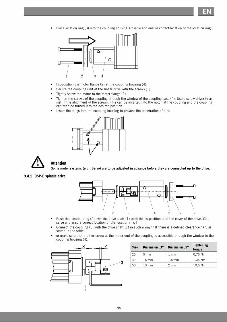
• Placelocationring(3)intothecouplinghousing.Observeandensurecorrectlocationofthelocationring!
• Fix-positionthemotorflange(2)atthecouplinghousing(4).• Securethecouplingunitatthelineardrivewiththescrews(1).• Tightlyscrewthemotortothemotorflange(2).• Tightenthescrewsofthecouplingthroughthewindowofthecouplingcase(4).Useascrewdrivertoas-
sistinthealignmentofthescrews.Thiscanbeinsertedintothenotchatthecouplingandthecouplingcan then be turned into the desired position.
• Inserttheplugsintothecouplinghousingtopreventthepenetrationofdirt.
AttentionSome motor systems (e.g., Servo) are to be adjusted in advance before they are connected up to the drive.
9.4.2 OSP-E spindle drive
• Pushthelocationring(2)overthedriveshaft(1)untilthisispositionedinthecoverofthedrive.Ob-serveandensurecorrectlocationofthelocationring!
• Connectthecoupling(3)withthedriveshaft(1)insuchawaythatthereisadefinedclearance“X”,asstated in the table
• ormakesurethatthehexscrewatthemotorendofthecouplingisaccessiblethroughthewindowinthecoupling housing (4).
Size Dimension „X“ Dimension „Y“Tightening torque
25 5 mm 1 mm 0,76Nm
32 15 mm 1,5mm 1,34Nm
50 13 mm 2 mm 10,5Nm
3 41 2
36
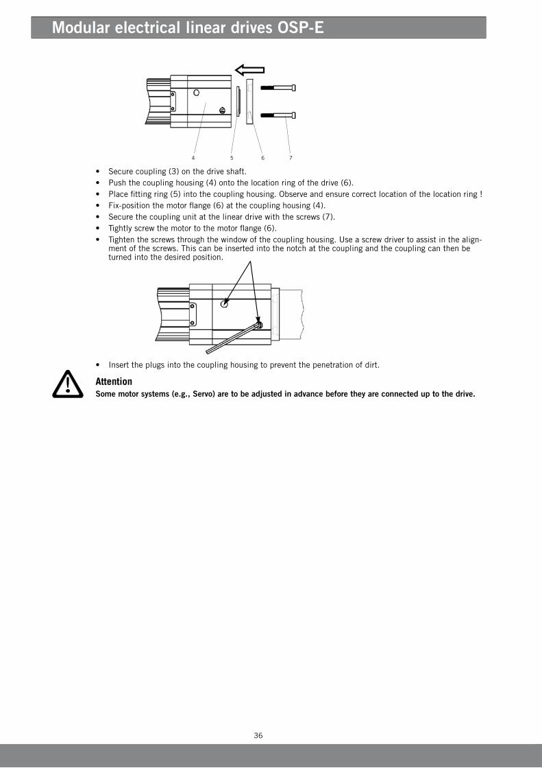
Modular electrical linear drives OSP-E
• Securecoupling(3)onthedriveshaft.• Pushthecouplinghousing(4)ontothelocationringofthedrive(6).• Placefittingring(5)intothecouplinghousing.Observeandensurecorrectlocationofthelocationring!• Fix-positionthemotorflange(6)atthecouplinghousing(4).• Securethecouplingunitatthelineardrivewiththescrews(7).• Tightlyscrewthemotortothemotorflange(6).• Tightenthescrewsthroughthewindowofthecouplinghousing.Useascrewdrivertoassistinthealign-
mentofthescrews.Thiscanbeinsertedintothenotchatthecouplingandthecouplingcanthenbeturned into the desired position.
• Inserttheplugsintothecouplinghousingtopreventthepenetrationofdirt.
AttentionSome motor systems (e.g., Servo) are to be adjusted in advance before they are connected up to the drive.

37
EN
Tightening torqueM5:5,5±0.8NmM6:10±1.5NmLoctite 243 (ID 3183)
Tightening torqueM4:3±0.5NmM5:5,5±0.8NmM6:10±1.5NmM8:20±1.5NmM10:40±6NmLoctite 243 (ID 3183)
Fitwiththeslotatrightangles to the set screw
Identification plate
Tightening torqueM6:6±0.5NmM8:10±1NmM10:23±2NmLoctite 243 (ID 3183)
Fitwiththestopofthesleeve to the top
Tightening torque5.5±0.8NmLoctite 243 (ID 3183)
POS DESIGNATION
A FLANGEPLATE
B COVER
C COGBELTWHEELAT5DRIVESIDE
D COGBELTWHEELAT5MOTORSIDE
E CLAMPINGSLEEVE
F COGBELT
G SOCkETSETSCREWDRIVESIDE
H SOCkETSETSCREWMOTORSIDE
J SOCkETHEADCAPSCREWDRIVESIDE
k SOCkETHEADCAPSCREWMOTORSIDE
L COUNTERSUNkSCREWM3X10DIN7991
IDENTIFICATIONPLATE
Parts for the option „smooth drive shaft“
POS DESIGNATION
C COGBELTWHEELACTUATORAT5DRIVESIDE
M CLAMPINGSLEEVE
9.5 Synchronous belt drive with configuration capability
9.5.1 Design Features

38
Modular electrical linear drives OSP-E
9.5.2 Sequence of assembly:
Pay attention to tightening torque.• Fitthemotortotheflangeplate.• Fitthelineardrivetotheflangeplateensuringthattheaxlescentresaresetatthecorrectdistance
appart. (See table)• Pushonbeltwheelsandfeedontimingbelt.(Seedrawing)• Settheclearencebetweenthebeltwheelandflangefaceto1.5+/-0.5mmandtightenthelocking
screws.• Installtoothedbeltsandcorrectcentredistanceifnecessary.• Fitthecoverplate.
Size OSP-E25 OPS-E32 OSP-E50
Transmission ratio 1:1 2:1 1:1 2:1 1:1 2:1
Axle-centres [mm] 110 109.3 110 111.4 135 133.7
Axle-centres
39
EN
10 Manufacturer’s statement
Parker-Origa GmbH
40
Modular electrical linear drives OSP-E
Supplied kits
11 Spare part lists
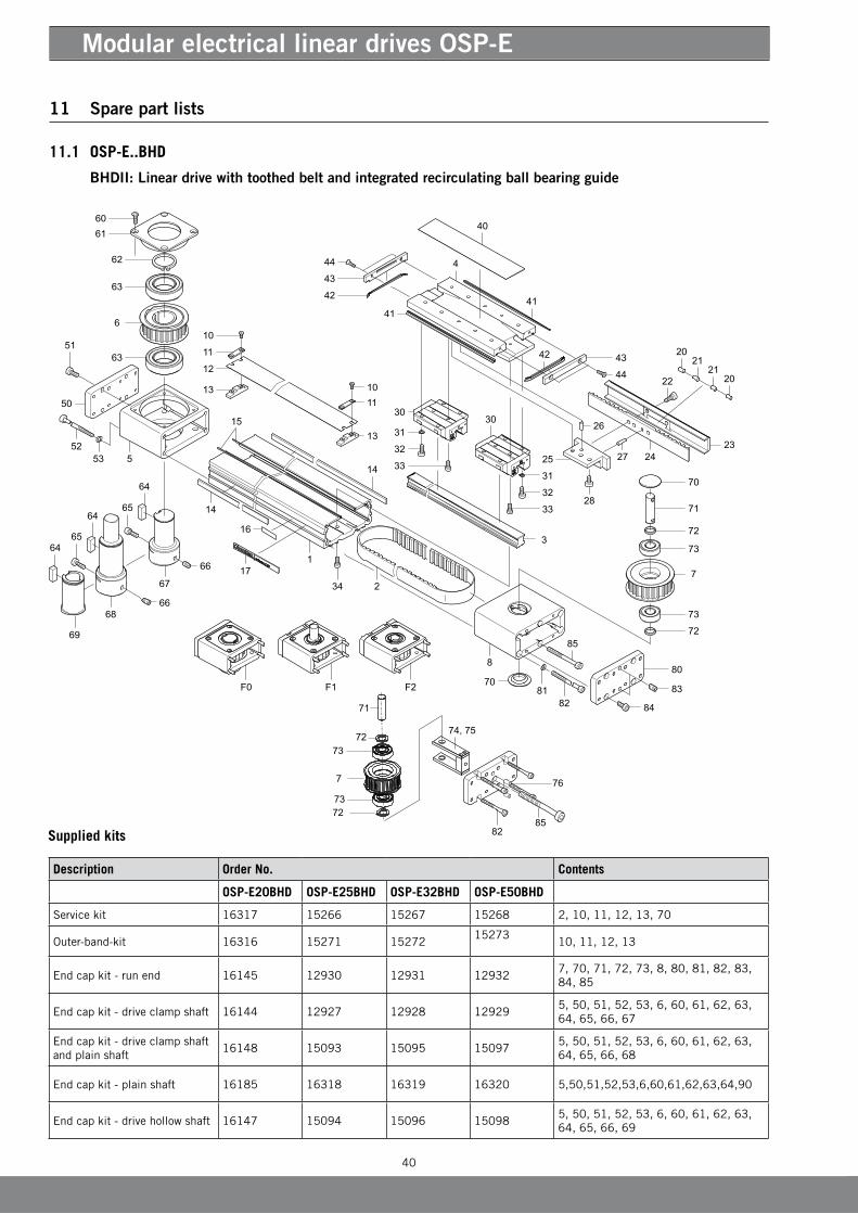
11.1 OSP-E..BHD (Recirculating ball bearing guide)
BHDII: Linear drive with toothed belt and integrated recirculating ball bearing guide
Description Order No. Contents
OSP-E20BHD OSP-E25BHD OSP-E32BHD OSP-E50BHD
Servicekit 16317 15266 15267 15268 2,10,11,12,13,70
Outer-band-kit 16316 15271 1527215273
10,11,12,13
Endcapkit-runend 16145 12930 12931 129327,70,71,72,73,8,80,81,82,83,84,85
Endcapkit-driveclampshaft 16144 12927 12928 129295,50,51,52,53,6,60,61,62,63,64,65,66,67
Endcapkit-driveclampshaftandplainshaft
16148 15093 15095 150975,50,51,52,53,6,60,61,62,63,64,65,66,68
Endcapkit-plainshaft 16185 16318 16319 16320 5,50,51,52,53,6,60,61,62,63,64,90
Endcapkit-drivehollowshaft 16147 15094 15096 150985,50,51,52,53,6,60,61,62,63,64,65,66,69

41
EN
POS. DESCRIPTION POS. DESCRIPTION
1 CyLINDERBARRELOSP-E..BHD
2 TOOTH BELT OSP-E..BHD
3 GUIDERAILOSP-E..BHD
4 CARRIER OSP-E..BHD
5 CAPACTUATOROSP-E..BHD
6 TOOTHBELTWHEELACTUATOROSP-E..BHD
7 TOOTHBELTWHEELCIRCULATIONOSP-E..BHD
8 ENDCAPRUNENDOSP-E..BHD
10 COUNTERSUNkSCREWDIN7991
11 CLAMPINGPIECEFOROUTERBANDOSP-E..BHD
12 OUTERBANDOSP-E..BHD
13 CLAMPINGPIECEFORINNERBANDOSP-E..BHD-II
14 COVER RAIL
15 MAGNETICSTRIP
16 IDENTIFICATIONPLATE
17 COVER RAIL- LABEL
20 STEEL BOLT (2*OSP-E20BHD,25BHD,32BHD/3*OSP-E50BHD)
21 MAGNET (1*OSP-E20BHD / 6*OSP-E25BHD / 2*OSP-E32BHD / 3*OSP-E50BHD)
22 SOCkETHEADCAPSCREWDIN6912
23 CLAMPINGPLATEOSP-E..BHD
24 TOOTH BELT kEyLOCk OSP-E..BHD
25 TOOTH BELT SHACkLE PLATE OSP-E..BHD-II
26 ROLLPINDIN6325 ONLyOSP-E32BHDANDOSP-E50BHD
27 ROLLPINDIN7
28 SOCkETHEADCAPSCREWDIN7984
30 GUIDEDCARRIAGEOSP-E..BHD
31 WASHER
32 SOCkETHEADCAPSCREWDIN912
33 SOCkETHEADCAPSCREWDIN7984
34 SOCkETHEADCAPSCREWDIN7984
40 COVER OSP-E..BHD
41 SIDEWIPER
42 WIPERGABLEEND
43 WIPERCOVER
44 COUNTERSUNkSCREWDIN7991
50 COVERPLATEACTUATORFOROSP-E..BHD
51 SOCkETHEADCAPSCREWDIN912
52 SOCkETHEADCAPSCREWDIN912
53 WASHER
60 COUNTERSUNkSCREWDIN7991
61 COVERCAPACTUATOROSP-E..BHD
62 WASHERDIN471
63 BALLBEARING
64 kEyDIN6885
65 SOCkETHEADCAPSCREWDIN912
66 SOCkETSETSCREWDIN913
67 CLAMPSHAFT
68 CLAMPSHAFTWITHPLAINSHAFT
69 HOLLOWSHAFTWITHkEyWAy
70 COVERCAP(NOTOSP-E20BHD)
71 AXLECIRCULATIONOSP-E..BHD
72 DISTANCERINGOSP-E..BHD
73 BALLBEARING
80 COVERPLATECIRCULATIONOSP-E..BHD
81 WASHER
82 SOCkETHEADCAPSCREWDIN912
83 SOCkETSETSCREWDIN913
84 SOCkETHEADCAPSCREWDIN912
85 SOCkETHEADCAPSCREWDIN912

42
Modular electrical linear drives OSP-E
Supplied kits
11.2 OSP-E..BHD (Roller Guide)
BHD: Linear drive with toothed belt and integrated roller guide
F0 F1 F2
18
3231
26
29
46
28 43
48
50
4
44
40
39
36
40
39
34
38
41
3231
42
42
37
35
43
8
73
8
7
20
21
1927
26
30
24
25
34 33
23
47
1
2
20
22
196
119
10
14
1212
13
13
15
16
19
17
15
5
21
45
1617
19
49
28
28
Description Order No. Contents
OSP-E25BHD OSP-E32BHD OSP-E50BHD
Servicekit 15266 15267 15268 19,20,21,22,42,44
Outer-band-kit 15271 15272 15273 19,20,21,22
Endcapkit-runend 12930 12931 1293231,32,34,35,36,37,38,39,40,41,42,43
Endcapkit-driveclampshaft
12927 12928 1292923,24,25,26,27,28,29,30,31,32,33,34,43,46
Endcapkit-clampshaftwithplainshaft
15093 15095 1509723,24,25,26,27,28,29,30,31,32,33,34,43,46
Endcapkit-driveplain 16318 16319 16320 5,50,51,52,53,6,60,61,62,63,64,90
Endcapkit-drivehollowshaft
15094 15096 1509823,24,25,26,27,28,29,30,31,32,33,34
43
EN
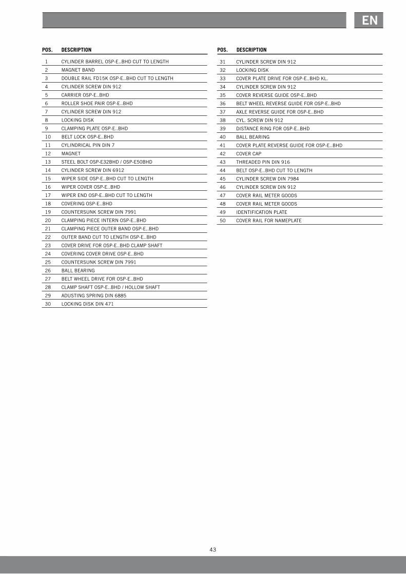
POS. DESCRIPTIONPOS. DESCRIPTION
1 CyLINDERBARRELOSP-E..BHDCUTTOLENGTH
2 MAGNETBAND
3 DOUBLERAILFD15kOSP-E..BHDCUTTOLENGTH
4 CyLINDERSCREWDIN912
5 CARRIER OSP-E..BHD
6 ROLLER SHOE PAIR OSP-E..BHD
7 CyLINDERSCREWDIN912
8 LOCkINGDISk
9 CLAMPINGPLATEOSP-E..BHD
10 BELT LOCk OSP-E..BHD
11 CyLINDRICALPINDIN7
12 MAGNET
13 STEEL BOLT OSP-E32BHD / OSP-E50BHD
14 CyLINDERSCREWDIN6912
15 WIPERSIDEOSP-E..BHDCUTTOLENGTH
16 WIPERCOVEROSP-E..BHD
17 WIPERENDOSP-E..BHDCUTTOLENGTH
18 COVERINGOSP-E..BHD
19 COUNTERSUNkSCREWDIN7991
20 CLAMPINGPIECEINTERNOSP-E..BHD
21 CLAMPINGPIECEOUTERBANDOSP-E..BHD
22 OUTERBANDCUTTOLENGTHOSP-E..BHD
23 COVERDRIVEFOROSP-E..BHDCLAMPSHAFT
24 COVERINGCOVERDRIVEOSP-E..BHD
25 COUNTERSUNkSCREWDIN7991
26 BALLBEARING
27 BELTWHEELDRIVEFOROSP-E..BHD
28 CLAMPSHAFTOSP-E..BHD/HOLLOWSHAFT
29 ADUSTINGSPRINGDIN6885
30 LOCkINGDISkDIN471
31 CyLINDERSCREWDIN912
32 LOCkINGDISk
33 COVERPLATEDRIVEFOROSP-E..BHDkL.
34 CyLINDERSCREWDIN912
35 COVERREVERSEGUIDEOSP-E..BHD
36 BELTWHEELREVERSEGUIDEFOROSP-E..BHD
37 AXLEREVERSEGUIDEFOROSP-E..BHD
38 CyL.SCREWDIN912
39 DISTANCERINGFOROSP-E..BHD
40 BALLBEARING
41 COVERPLATEREVERSEGUIDEFOROSP-E..BHD
42 COVER CAP
43 THREADEDPINDIN916
44 BELTOSP-E..BHDCUTTOLENGTH
45 CyLINDERSCREWDIN7984
46 CyLINDERSCREWDIN912
47 COVER RAIL METER GOODS
48 COVER RAIL METER GOODS
49 IDENTIFICATIONPLATE
50 COVERRAILFORNAMEPLATE

44
Modular electrical linear drives OSP-E
11.3 OSP-E..BV
Vertical linear drive with tooth belt and integrated recirculating ball bearing guide

45
EN
POS DESCRIPTIONPOS. DESCRIPTION
1 CyLINDERBARRELOSP-E..BV
2 TOOTHED BELT OSP-E..BV
3 GUIDERAILOSP-E..BV
4 CAPACTUATOROSP-E..BV
5 TOOTHED BELT DRIVE OSP-E..BV
6 CLAMPSHAFT
7 TOOTHBELTWHEELCIRCULATIONOSP-E..BV
10 COVER PLATE OSP-E..BV
11 SOCkETHEADCAPSCREWDIN912
12 SCREWFORCOVER
13 SOCkETSETSCREWDIN916
14 COVER RAIL
15 IDENTIFICATIONPLATE
16 COVERRAILIDENTIFICATIONPLATE
20 BELT LOCk OSP-E..BV
21 CLAMPINGPLATEOSP-E..BV
22 CyLINDRICALPINDIN6325
24 SOCkETHEADCAPSCREWDIN7984
30 GUIDEDCARRIAGEOSP-E..BV
31 CARRIER PLATE OSP-E..BV
32 COVER PLATE OSP-E..BV
33 SOCkETHEADCAPSCREWDIN7984
34 LOCkWASHER
35 LOCkWASHER
36 SOCkETHEADCAPSCREWDIN912
37 SOCkETHEADCAPSCREWDIN6912
38 SOCkETHEADCAPSCREWDIN7984
40 COVER PLATE DRIVE OSP-E..BV
41 SOCkETHEADCAPSCREWDIN7984
42 LOCkWASHER
43 SOCkETHEADCAPSCREWDIN912
44 LOCkWASHER
45 COVERCAPGPN910/4010
46 PLUG7D
47 PLUGM6
50 COUNTERSUNkSCREWDIN7991
51 COVERCAPACTUATOROSP-E..BV
52 LOCkWASHERDIN471
53 BALLBEARING
54 kEyWAy
55 SOCkETHEADCAPSCREWDIN912
56 SOCkETSETSCREWDIN913
60 SHAFTWITHPLAIN
61 CLAMPSHAFTWITHPLAINSHAFT
62 CLAMPSHAFTWITHPLAINSHAFTDOUBLESIDED
63 HOLLOWSHAFTWITHkEyWAy
70 LOCkWASHERDIN472
71 DISTANCERING
72 BALLBEARING
73 kEEPER
90 LOCk RAIL
92 SOCkETHEADCAPSCREW
93 MAGNET
94 kL3087(RS-SNC)

46
Modular electrical linear drives OSP-E
Supplied kits
11.4 OSP-E..B
Linear Drive with toothed belt and internal plain bearing guide
Description Order No. Contents
OSP-E25B OSP-E32B OSP-E50B
Sealkit 12110 12111 121124,5,19,21,22,28,29,30,31,34,40,43
Servicekit 15247 15248 15249 Sealkit+2,10
Carrierkit 12172 12173 121743,4,5,6,7,19,28,29,30,31,34,39,40,41
Endcapkitrunningunit 12113 12117 121219,12,13,14,15,16,18,20,21,22,24,25,26
Endcapkitshaft0 12114 / 15277* 12118 / 15280* 12122 / 15283*8,15,17,21,23,26,27,32,33,35,45,46,47,48
Endcapkitshaft1 12115 / 15278* 12119 / 15281* 12123 / 15284*8,15,17,21,23,26,27,32,33,35,45,46,47,48
Endcapkitshaft2 12116 / 15279* 12120 / 15282* 12124 / 15285*8,15,17,21,23,26,27,32,33,35,45,46,47,48
*) Stainless steel version

47
EN
POS. DESCRIPTION POS. DESCRIPTION
1 CyLINDERBARRELOSP-E..BCUTTOLENGTH
2 OUTERBANDCUTTOLENGTHOSP-E..B
3 CARRIER OSP-E..B
4 SUPPORTRINGOSP-E..B
5 BEARINGSTRIPOSP-E..B
6 MAGNETHOUSINGFOROSP-E..B
7 MAGNET10DX3LFOROSP-E..B
8 DRIVEENDCAPFOROSP-E..B
9 RUNENDCAPFOROSP-E..B
10 BELTOSP-E..BCUTTOLENGTH
11 SHAFTONE-SIDEOSP-E32B/OSP-E50B
12 AXLEREVERSEGUIDEFOROSP-E..B
13 BELTWHEELREVERSEGUIDEFOROSP-E..B
14 BEARINGHOUSINGFOROSP-E..B
15 CLAMPINGPIECEEXTERN
16 SCREWFORCOVER
17 COVERPLATEFOROSP-E..B
18 BALLBEARING
19 CyLINDERSCREW
20 CyLINDRICALPINDIN6325
21 X-RING
22 O-RING
23 CyLINDERSCREWDIN912
24 THREADEDPINDIN916
25 CyLINDERSCREWDIN912
26 COUNTERSUNkSCREWDIN963
27 CyLINDERSCREWDIN912
28 COVER
29 WIPER
30 SIDEWIPERCUTTOLENGTHONSIDE
31 THRUSTSPRINGFORWIPER
32 BALLBEARING
33 CIRCLIPDIN472
34 O-RING
35 PLUGPLASTICFORSECURINGBOREHOLES
36 COVERRAILFORNAMEPLATE
37 COVER RAIL METER GOODS
38 COVER RAIL METER GOODS
39 BOLTFORMAGNET
40 COUNTERSUNkSCREWDIN7991
41 MAGNETOSP-E32B
42 GREASENIPPLEA1
43 GREASEFORGUIDE
44 IDENTIFICATIONPLATEOSP
45 BRACINGPINDIN7343OSP-E25B
46 BELTWHEELDRIVEFOROSP-E25B
47 DISTANCERINGFOROSP-E25B
48 SHAFTONESIDEOSP-E25B
48
Modular electrical linear drives OSP-E
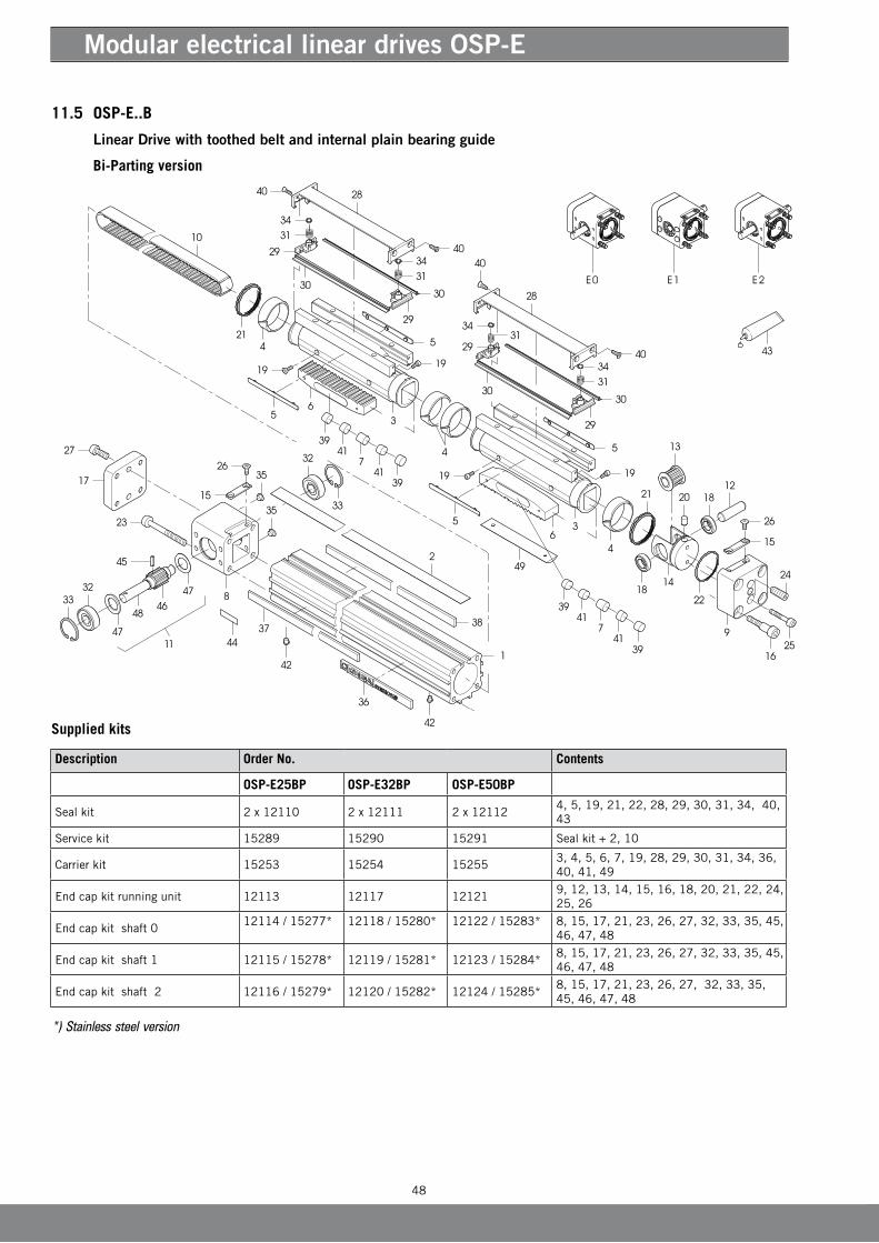
11.5 OSP-E..B (Bi-Parting version)
Linear Drive with toothed belt and internal plain bearing guide
Bi-Parting version
Supplied kits
Description Order No. Contents
OSP-E25BP OSP-E32BP OSP-E50BP
Sealkit 2 x 12110 2 x 12111 2 x 121124,5,19,21,22,28,29,30,31,34,40,43
Servicekit 15289 15290 15291 Sealkit+2,10
Carrierkit 15253 15254 152553,4,5,6,7,19,28,29,30,31,34,36,40,41,49
Endcapkitrunningunit 12113 12117 121219,12,13,14,15,16,18,20,21,22,24,25,26
Endcapkitshaft012114 / 15277* 12118 / 15280* 12122 / 15283* 8,15,17,21,23,26,27,32,33,35,45,
46,47,48
Endcapkitshaft1 12115 / 15278* 12119 / 15281* 12123 / 15284*8,15,17,21,23,26,27,32,33,35,45,46,47,48
Endcapkitshaft2 12116 / 15279* 12120 / 15282* 12124 / 15285*8,15,17,21,23,26,27,32,33,35,45,46,47,48
*) Stainless steel version
49
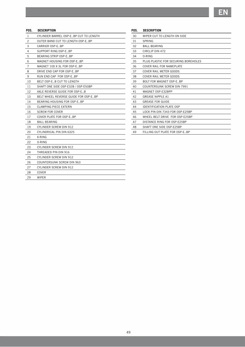
EN
1 CyLINDERBARRELOSP-E..BPCUTTOLENGTH
2 OUTERBANDCUTTOLENGTHOSP-E..BP
3 CARRIER OSP-E..BP
4 SUPPORTRINGOSP-E..BP
5 BEARINGSTRIPOSP-E..BP
6 MAGNETHOUSINGFOROSP-E..BP
7 MAGNET10DX3LFOROSP-E..BP
8 DRIVEENDCAPFOROSP-E..BP
9 RUNENDCAPFOROSP-E..BP
10 BELTOSP-E..BCUTTOLENGTH
11 SHAFTONESIDEOSP-E32B/OSP-E50BP
12 AXLEREVERSEGUIDEFOROSP-E..B
13 BELTWHEELREVERSEGUIDEFOROSP-E..BP
14 BEARINGHOUSINGFOROSP-E..BP
15 CLAMPINGPIECEEXTERN
16 SCREWFORCOVER
17 COVERPLATEFOROSP-E..BP
18 BALLBEARING
19 CyLINDERSCREWDIN912
20 CyLINDRICALPINDIN6325
21 X-RING
22 O-RING
23 CyLINDERSCREWDIN912
24 THREADEDPINDIN916
25 CyLINDERSCREWDIN912
26 COUNTERSUNkSCREWDIN963
27 CyLINDERSCREWDIN912
28 COVER
29 WIPER
30 WIPERCUTTOLENGTHONSIDE
31 SPRING
32 BALLBEARING
33 CIRCLIPDIN472
34 O-RING
35 PLUGPLASTICFORSECURINGBOREHOLES
36 COVERRAILFORNAMEPLATE
37 COVER RAIL METER GOODS
38 COVER RAIL METER GOODS
39 BOLTFORMAGNETOSP-E..BP
40 COUNTERSUNkSCREWDIN7991
41 MAGNETOSP-E32BPP
42 GREASENIPPLEA1
43 GREASEFORGUIDE
44 IDENTIFICATIONPLATEOSP
45 LOCkPINDIN7343FOROSP-E25BP
46 WHEELBELTDRIVEFOROSP-E25BP
47 DISTANCERINGFOROSP-E25BP
48 SHAFTONESIDEOSP-E25BP
49 FILLINGOUTPLATEFOROSP-E..BP
POS. DESCRIPTION POS. DESCRIPTION
50
Modular electrical linear drives OSP-E
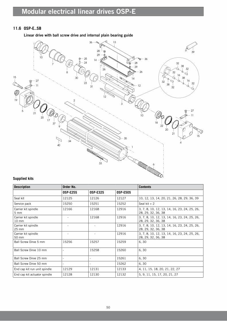
11.6 OSP-E..SB
Linear drive with ball screw drive and internal plain bearing guide
Description Order No. Contents
OSP-E25S OSP-E32S OSP-E50S
Sealkit 12125 12126 12127 10,12,13,14,20,21,26,28,29,36,39
Servicepack 15250 15251 15252 Sealkit+2
Carrierkitspindle5 mm
12166 12168 12916 3,7,8,10,12,13,14,16,23,24,25,26,28,29,32,36,38
Carrierkitspindle10 mm
- 12168 12916 3,7,8,10,12,13,14,16,23,24,25,26,28,29,32,36,38
Carrierkitspindle25 mm
- - 12916 3,7,8,10,12,13,14,16,23,24,25,26,28,29,32,36,38
Carrierkitspindle50 mm
- - 12916 3,7,8,10,12,13,14,16,23,24,25,26,28,29,32,36,38
Ball Screw Dirve 5 mm 15256 15257 15259 6,30
Ball Screw Dirve 10 mm - 15258 15260 6,30
Ball Screw Dirve 25 mm - - 15261 6,30
Ball Screw Dirve 50 mm - - 15262 6,30
Endcapkitrununitspindle 12129 12131 12133 4,11,15,18,20,21,22,27
Endcapkitactuatorspindle 12128 12130 12132 5,9,11,15,17,20,21,27
Supplied kits
51
EN
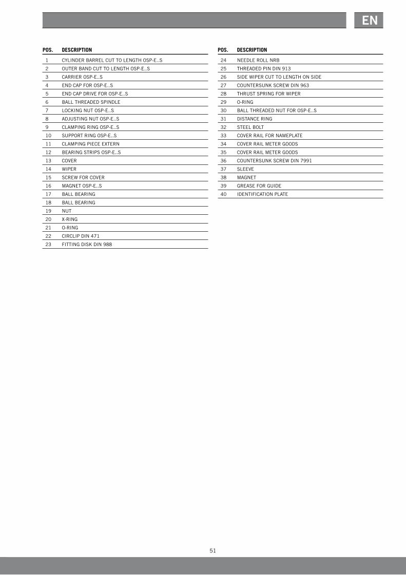
POS. DESCRIPTIONPOS. DESCRIPTION
1 CyLINDERBARRELCUTTOLENGTHOSP-E..S
2 OUTERBANDCUTTOLENGTHOSP-E..S
3 CARRIER OSP-E..S
4 ENDCAPFOROSP-E..S
5 ENDCAPDRIVEFOROSP-E..S
6 BALLTHREADEDSPINDLE
7 LOCkINGNUTOSP-E..S
8 ADJUSTINGNUTOSP-E..S
9 CLAMPINGRINGOSP-E..S
10 SUPPORTRINGOSP-E..S
11 CLAMPINGPIECEEXTERN
12 BEARINGSTRIPSOSP-E..S
13 COVER
14 WIPER
15 SCREWFORCOVER
16 MAGNETOSP-E..S
17 BALLBEARING
18 BALLBEARING
19 NUT
20 X-RING
21 O-RING
22 CIRCLIPDIN471
23 FITTINGDISkDIN988
24 NEEDLEROLLNRB
25 THREADEDPINDIN913
26 SIDEWIPERCUTTOLENGTHONSIDE
27 COUNTERSUNkSCREWDIN963
28 THRUSTSPRINGFORWIPER
29 O-RING
30 BALLTHREADEDNUTFOROSP-E..S
31 DISTANCERING
32 STEEL BOLT
33 COVERRAILFORNAMEPLATE
34 COVER RAIL METER GOODS
35 COVER RAIL METER GOODS
36 COUNTERSUNkSCREWDIN7991
37 SLEEVE
38 MAGNET
39 GREASEFORGUIDE
40 IDENTIFICATIONPLATE

52
Modular electrical linear drives OSP-E
Description Order No. Contents
OSP-E25ST OSP-E32ST OSP-E50ST
Sealkit 12125 12126 12127 8,10,11,12,17,18,22,24,25,31,33
Servicepack 15250 15251 15252 sealkit+2
Carrierkit 12816 12825 128343,8,10,11,12,21,22,24,25,26,27,31,32
Endcapkitrununitspindle 12129 12131 12133 4,9,13,15,17,18,19,23
Endcapkitactuatorspindle 12128 15617 15618 5,9,13,14,17,18,20,23
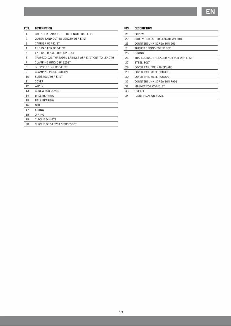
11.7 OSP-E..ST
Linear drive with trapezoidal screw drive and internal plain bearing guide
Supplied kits
53
EN
POS. DESCRIPTIONPOS. DESCRIPTION
1 CyLINDERBARRELCUTTOLENGTHOSP-E..ST
2 OUTERBANDCUTTOLENGTHOSP-E..ST
3 CARRIER OSP-E..ST
4 ENDCAPFOROSP-E..ST
5 ENDCAPDRIVEFOROSP-E..ST
6 TRAPEZOIDALTHREADEDSPINDLEOSP-E..STCUTTOLENGTH
7 CLAMPINGRINGOSP-E25ST
8 SUPPORTRINGOSP-E..ST
9 CLAMPINGPIECEEXTERN
10 SLIDE RAIL OSP-E..ST
11 COVER
12 WIPER
13 SCREWFORCOVER
14 BALLBEARING
15 BALLBEARING
16 NUT
17 X-RING
18 O-RING
19 CIRCLIPDIN471
20 CIRCLIP OSP-E32ST / OSP-E50ST
21 SCREW
22 SIDEWIPERCUTTOLENGTHONSIDE
23 COUNTERSUNkSCREWDIN963
24 THRUSTSPRINGFORWIPER
25 O-RING
26 TRAPEZOIDALTHREADEDNUTFOROSP-E..ST
27 STEEL BOLT
28 COVERRAILFORNAMEPLATE
29 COVER RAIL METER GOODS
30 COVER RAIL METER GOODS
31 COUNTERSUNkSCREWDIN7991
32 MAGNETFOROSP-E..ST
33 GREASE
34 IDENTIFICATIONPLATE
54
Modular electrical linear drives OSP-E
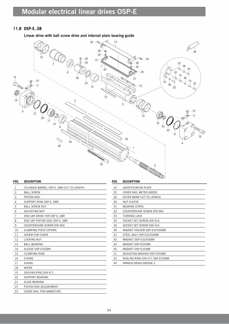
11.8 OSP-E..SB
Linear drive with ball screw drive and internal plain bearing guide
POS. DESCRIPTIONPOS. DESCRIPTION
1 CyLINDERBARRELOSP-E..SBRCUTTOLENGTH
2 BALLSCREW
3 PISTONROD
4 SUPPORTRINGOSP-E..SBR
5 BALLSCREWNUT
6 ADJUSTINGNUT
7 ENDCAPDRIVEFOROSP-E..SBR
8 ENDCAPPISTONSIDEOSP-E..SBR
9 COUNTERSUNkSCREWDIN965
10 CLAMPINGPIECEEXTERN
11 SCREWFORCOVER
12 LOCkINGNUT
13 BALLBEARING
14 SLEEVE OSP-E32SBR
15 CLAMPINGRING
16 O-RING
17 X-RING
18 WIPER
19 SEALINGRINGDIN471
20 SUPPORTBEARING
21 SLIDEBEARING
22 PISTONRODSECUREMENT
23 COVERRAILFORNAMEPLATE
24 IDENTIFICATIONPLATE
25 COVER RAIL METER GOODS
26 OUTERBANDCUTTOLENGTH
30 NUTSLEEVE
31 BEARINGSTRIPL
32 COUNTERSUNkSCREWDIN965
33 TURNINGLOCk
34 SOCkETSETSCREWDIN914
35 SOCkETSETSCREWDIN916
40 MAGNETHOLDEROSP-E32/50SBR
41 STEEL BOLT OSP-E32/50SBR
42 MAGNETOSP-E32/50SBR
43 MAGNETOSP-E32SBR
50 MAGNETOSP-E25SBR
51 ADJUSTINGWASHEROSP-E25SBR
52 SEALINGRINGDIN471OSP-E25SBR
99 PARkER-ORIGA GREASE 2
55
EN
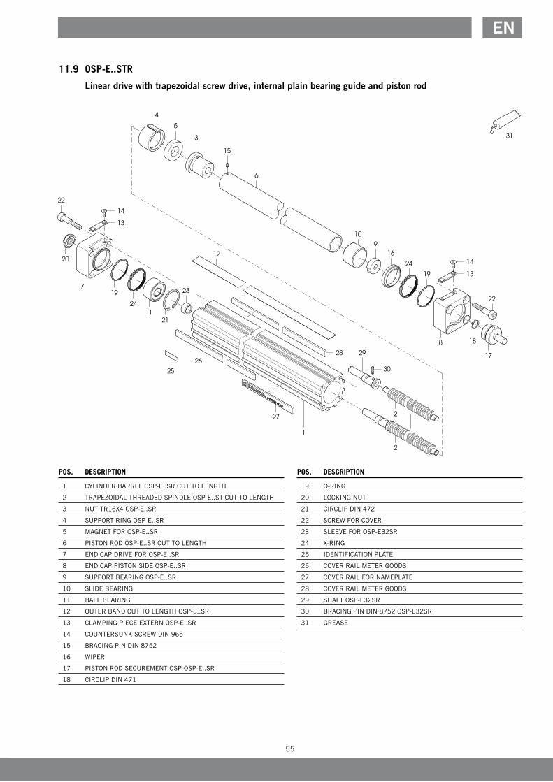
POS. DESCRIPTION
1 CyLINDERBARRELOSP-E..SRCUTTOLENGTH
2 TRAPEZOIDALTHREADEDSPINDLEOSP-E..STCUTTOLENGTH
3 NUTTR16X4OSP-E..SR
4 SUPPORTRINGOSP-E..SR
5 MAGNETFOROSP-E..SR
6 PISTONRODOSP-E..SRCUTTOLENGTH
7 ENDCAPDRIVEFOROSP-E..SR
8 ENDCAPPISTONSIDEOSP-E..SR
9 SUPPORTBEARINGOSP-E..SR
10 SLIDEBEARING
11 BALLBEARING
12 OUTERBANDCUTTOLENGTHOSP-E..SR
13 CLAMPINGPIECEEXTERNOSP-E..SR
14 COUNTERSUNkSCREWDIN965
15 BRACINGPINDIN8752
16 WIPER
17 PISTONRODSECUREMENTOSP-OSP-E..SR
18 CIRCLIPDIN471
POS. DESCRIPTION
19 O-RING
20 LOCkINGNUT
21 CIRCLIPDIN472
22 SCREWFORCOVER
23 SLEEVEFOROSP-E32SR
24 X-RING
25 IDENTIFICATIONPLATE
26 COVER RAIL METER GOODS
27 COVERRAILFORNAMEPLATE
28 COVER RAIL METER GOODS
29 SHAFTOSP-E32SR
30 BRACINGPINDIN8752OSP-E32SR
31 GREASE
11.9 OSP-E..STR
Linear drive with trapezoidal screw drive, internal plain bearing guide and piston rod

Your competent partner with global service and distribution.AE – United Arabien Emirates
DubaiTel: +971 4 [email protected] – Argentina, Buenos AiresTel: +54 3327 44 4129AT – Austria, Wiener NeustadtTel: +43 (0)2622 23501-0 [email protected] – Austria, Wiener Neustadt(Europa Oriental) Tel: +43 (0)2622 23501 970 [email protected] – Austria, Wiener NeustadtParker Origa Pneumatik GmbH Tel: +43 2622 26071-269 [email protected] – Australia, Castle HillTel: +61 (0)2-9634 7777AZ – Azerbaijan, BakuTel: +994 50 2233 458 [email protected]/LX – Belgium, NivellesTel: +32 (0)67 280 900 [email protected] – Brazil, Cachoeirinha RSTel: +55 51 3470 9144BY – Belarus, MinskTel: +375 17 209 9399 [email protected] – Canada, Milton, OntarioTel: +1 905 693 3000CH – Swiss, EtoyTel: +41 (0) 21 821 02 30 [email protected] – Swiss, Otelfingen Parker Origa AGTel +41 44 846 [email protected] – China, ShanghaiTel: +86 21 5031 2525CZ – Czechia, KlecanyTel: +420 284 083 111 [email protected] – Germany, KaarstTel: +49 (0)2131 4016 0 [email protected] – Denmark, BallerupTel: +45 43 56 04 00 [email protected] – Spain, MadridTel: +34 902 33 00 01 [email protected] – Finland, VantaaTel: +358 (0)20 753 2500 [email protected] – France Tel: +33 (0)4 50 25 80 25 [email protected]
FR – France, Courtaboef CedexParker Origa SASTel +33 1 69 29 22 [email protected] – Greece, AtenasTel: +30 210 933 6450 [email protected] – Hong KongTel: +852 2428 8008HU – Hungary, BudapestTel: +36 1 220 4155 [email protected] – Ireland, DublinTel: +353 (0)1 466 6370 [email protected] – India, MumbaiTel: +91 22 6513 7081-85IT – Italy, Corsico (MI)Tel: +39 02 45 19 21 [email protected] – Italy, Pioltello (MI) Parker Origa SRLTel +39 02 92 16 65 [email protected] – Japan, FujisawaTel: +(81) 4 6635 3050KR – Korea, SeúlTel: +82 2 559 0400KZ – Kazakhstan, AlmatyTel: +7 7272 505 800 [email protected] – Latvia, RigaTel: +371 6 745 2601 [email protected] – Mexico, ApodacaTel: +52 81 8156 6000MY – Malaysia, Subang JayaTel: +60 3 5638 1476MY – Malaysia, PenangParker Origa Sdn BhdTel +60 4 508 10 [email protected] – Netherlands, OldenzaalTel: +31 (0)541 585 000 [email protected] – Netherlands, SL MoerdijkParker Origa B.V. Tel +31 168 356 [email protected] – Norway, SkiTel: +47 64 91 10 00 [email protected] – Norway, DrammenParker Origa ASTel +47 3 288 08 40 [email protected] – New ZealandMt Wellington Tel: +64 9 574 1744
PL – Poland, VarsoviaTel: +48 (0)22 573 24 00 [email protected] – Portugal, Leca da PalmeiraTel: +351 22 999 7360 [email protected] – Romania, BucarestTel: +40 21 252 1382 [email protected] – Russia, MoscowTel: +7 495 645-2156 [email protected] – Sweden, SpångaTel: +46 (0)8 59 79 50 00 [email protected] – Sweden, KungsörParker Origa ABTel +46 227 411 [email protected] – SingaporTel: +65 6887 6300SG – SingaporParker Origa PTE Ltd.Tel. +65 6483 [email protected] – Slovakia, Banská BystricaTel: +421 484 162 252 [email protected] – Slovenia, Novo MestoTel: +386 7 337 6650 [email protected] – Thailand, BangkokTel: +662 717 8140TR – Turkey, IstanbulTel: +90 216 4997081 [email protected] – Taiwan, TaipeiTel: +886 2 2298 8987UA – Ukraine, KievTel +380 44 494 2731 [email protected] – United Kingdom, GloucesterParker Origa Ltd. Tel +44 8700 [email protected] – United Kingdom, WarwickTel: +44 (0)1926 317 878 [email protected] – United States of America, Cleveland Tel: +1 216 896 3000US – United States of AmericaParker Origa CorporationTel +1 630 871 [email protected] – Venezuela, CaracasTel: +58 212 238 5422ZA – South Africa,Kempton Park Tel: +27 (0)11 961 0700 [email protected]
Parker-Origa GmbHIndustriestr. 870794 Filderstadt, DeutschlandTel. +49 7185 17030Fax +49 7158 64870www.parker-origa.com
P-A7P014E Nov. 2008
Sales Offices Worldwide
© 2008 Parker-Origa GmbH - The right to introduce technical modifications is reserved


![Culpable [Sanz Cerbino]](https://img.pdfslide.us/doc/110x75/577cdc241a28ab9e78a9fb4a/culpable-sanz-cerbino.jpg)