Embed Size (px)
Citation preview
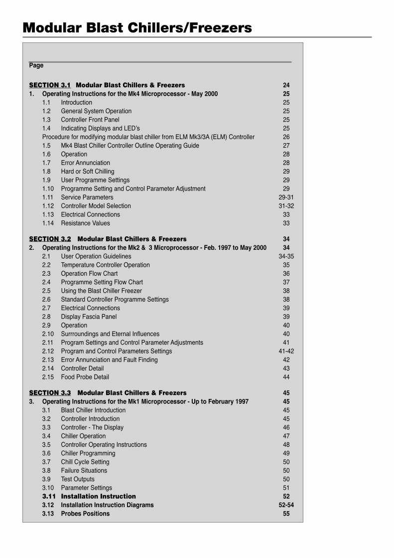
Page
SECTION 3.1 Modular Blast Chillers & Freezers 241. Operating Instructions for the Mk4 Microprocessor - May 2000 25 1.1 Introduction 25 1.2 General System Operation 25 1.3 Controller Front Panel 25 1.4 Indicating Displays and LED’s 25 Procedure for modifying modular blast chiller from ELM Mk3/3A (ELM) Controller 26 1.5 Mk4 Blast Chiller Controller Outline Operating Guide 27 1.6 Operation 28 1.7 Error Annunciation 28 1.8 Hard or Soft Chilling 29 1.9 User Programme Settings 29 1.10 Programme Setting and Control Parameter Adjustment 29 1.11 Service Parameters 29-31 1.12 Controller Model Selection 31-32 1.13 Electrical Connections 33 1.14 Resistance Values 33
SECTION 3.2 Modular Blast Chillers & Freezers 342. Operating Instructions for the Mk2 & 3 Microprocessor - Feb. 1997 to May 2000 34 2.1 User Operation Guidelines 34-35 2.2 Temperature Controller Operation 35 2.3 Operation Flow Chart 36 2.4 Programme Setting Flow Chart 37 2.5 Using the Blast Chiller Freezer 38 2.6 Standard Controller Programme Settings 38 2.7 Electrical Connections 39 2.8 Display Fascia Panel 39 2.9 Operation 40 2.10 Surrroundings and Eternal Influences 40 2.11 Program Settings and Control Parameter Adjustments 41 2.12 Program and Control Parameters Settings 41-42 2.13 Error Annunciation and Fault Finding 42 2.14 Controller Detail 43 2.15 Food Probe Detail 44
SECTION 3.3 Modular Blast Chillers & Freezers 453. Operating Instructions for the Mk1 Microprocessor - Up to February 1997 45 3.1 Blast Chiller Introduction 45 3.2 Controller Introduction 45 3.3 Controller - The Display 46 3.4 Chiller Operation 47 3.5 Controller Operating Instructions 48 3.6 Chiller Programming 49 3.7 Chill Cycle Setting 50 3.8 Failure Situations 50 3.9 Test Outputs 50 3.10 Parameter Settings 51 3.11 Installation Instruction 52 3.12 Installation Instruction Diagrams 52-54 3.13 Probes Positions 55
Modular Blast Chillers/Freezers

SECTION 1
Cabinet & Counter
BLAST CHILLERS & FREEZERS
3
4
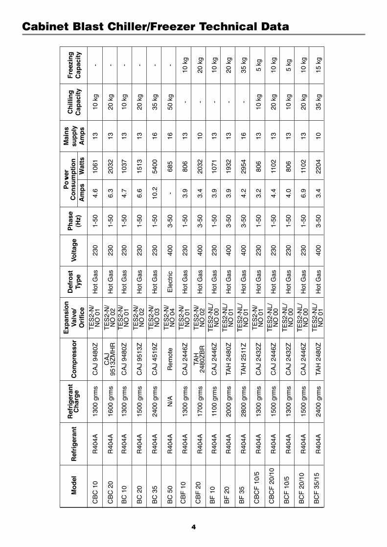
Cabinet Blast Chiller/Freezer Technical Data
E
xpan
sio
n
P
ow
er
Mai
ns
M
od
el
Ref
rig
eran
t R
efri
ger
ant
Co
mp
ress
or
Val
ve/
Def
rost
Vo
ltag
e P
has
e C
on
sum
pti
on
su
pp
ly
Ch
illin
g
Fre
ezin
g
C
har
ge
O
rifi
ce
Typ
e
(Hz)
A
mp
s
Wat
ts
Am
ps
Cap
acit
y C
apac
ity
CB
C 1
0 R
404A
13
00 g
rms
CA
J 94
80Z
T
ES
2-N
/ H
ot G
as
230
1-50
4.
6 10
61
13
10 k
g -
NO
01
CB
C 2
0 R
404A
16
00 g
rms
CA
J
TE
S2-
N/
Hot
Gas
23
0 1-
50
6.3
2032
13
20
kg
-
9513
ZM
HR
N
O 0
2
BC
10
R40
4A
1300
grm
s C
AJ
9480
Z
TE
S2-
N/
Hot
Gas
23
0 1-
50
4.7
1037
13
10
kg
-
N
O 0
1
BC
20
R40
4A
1500
grm
s C
AJ
9513
Z
TE
S2-
N/
Hot
Gas
23
0 1-
50
6.6
1513
13
20
kg
-
N
O 0
2
BC
35
R40
4A
2400
grm
s C
AJ
4519
Z
TE
S2-
N/
Hot
Gas
23
0 1-
50
10.2
54
00
16
35 k
g -
NO
03
BC
50
R40
4A
N/A
R
emot
e
TE
S2-
N/
Ele
ctric
40
0 3-
50
- 68
5 16
50
kg
-
N
O 0
4
CB
F 1
0 R
404A
13
00 g
rms
CA
J 24
46Z
T
ES
2-N
/ H
ot G
as
230
1-50
3.
9 80
6 13
-
10 k
g
N
O 0
1
CB
F 2
0 R
404A
17
00 g
rms
TAH
T
ES
2-N
/ H
ot G
as
400
3-50
3.
4 20
32
10
- 20
kg
24
80Z
BR
N
O 0
2
BF
10
R40
4A
1100
grm
s C
AJ
2446
Z
TE
S2-
NL/
H
ot G
as
230
1-50
3.
9 10
71
13
- 10
kg
NO
00
BF
20
R40
4A
2000
grm
s TA
H 2
480Z
T
ES
2-N
L/
Hot
Gas
40
0 3-
50
3.9
1932
13
-
20 k
g
N
O 0
1
BF
35
R40
4A
2800
grm
s TA
H 2
511Z
T
ES
2-N
L/
Hot
Gas
40
0 3-
50
4.2
2954
16
-
35 k
g
N
O 0
1
CB
CF
10/
5 R
404A
13
00 g
rms
CA
J 24
32Z
T
ES
2-N
/ H
ot G
as
230
1-50
3.
2 80
6 13
10
kg
5 kg
NO
01
CB
CF
20/
10
R40
4A
1500
grm
s C
AJ
2446
Z
TE
S2-
NL/
H
ot G
as
230
1-50
4.
4 11
02
13
20 k
g 10
kg
NO
00
BC
F 1
0/5
R40
4A
1300
grm
s C
AJ
2432
Z
TE
S2-
NL/
H
ot G
as
230
1-50
4.
0 80
6 13
10
kg
5 kg
NO
00
BC
F 2
0/10
R
404A
15
00 g
rms
CA
J 24
46Z
T
ES
2-N
L/
Hot
Gas
23
0 1-
50
6.9
1102
13
20
kg
10 k
g
N
O 0
0
BC
F 3
5/15
R
404A
24
00 g
rms
TAH
248
0Z
TE
S2-
NL/
H
ot G
as
400
3-50
3.
4 22
04
10
35 k
g 15
kg
NO
01
5
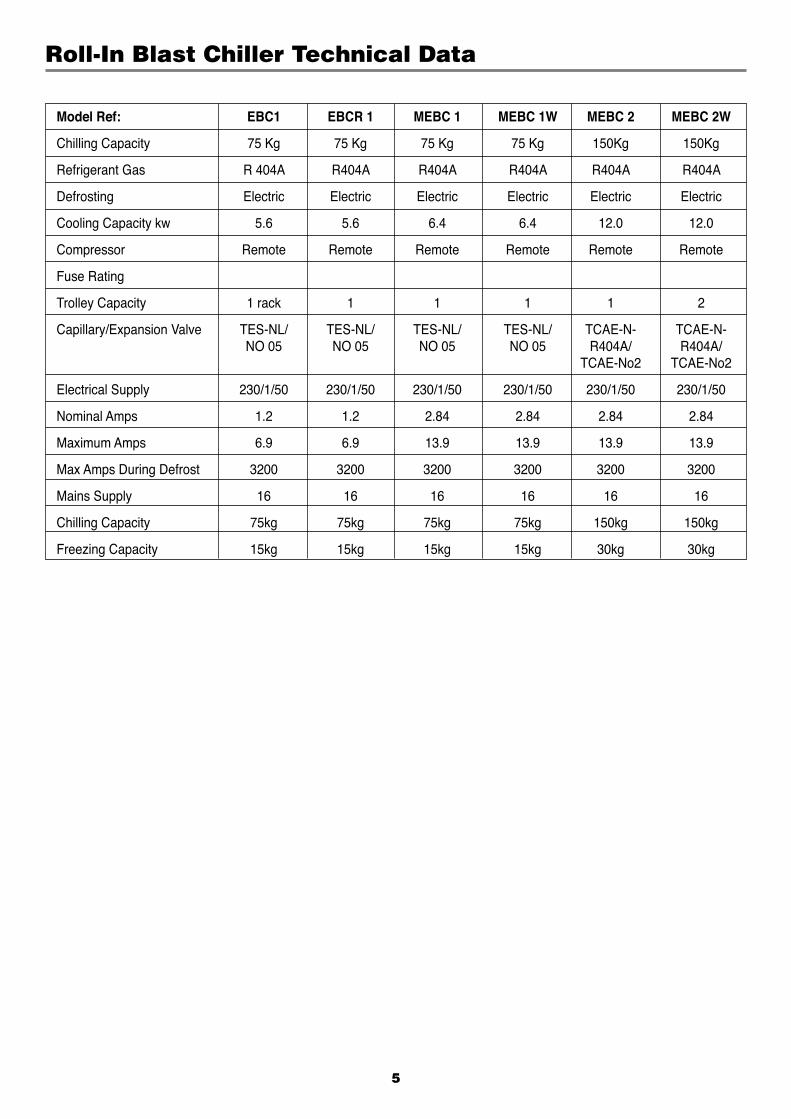
Roll-In Blast Chiller Technical Data
Model Ref: EBC1 EBCR 1 MEBC 1 MEBC 1W MEBC 2 MEBC 2W
Chilling Capacity 75 Kg 75 Kg 75 Kg 75 Kg 150Kg 150Kg
Refrigerant Gas R 404A R404A R404A R404A R404A R404A
Defrosting Electric Electric Electric Electric Electric Electric
Cooling Capacity kw 5.6 5.6 6.4 6.4 12.0 12.0
Compressor Remote Remote Remote Remote Remote Remote
Fuse Rating
Trolley Capacity 1 rack 1 1 1 1 2
Capillary/Expansion Valve TES-NL/ TES-NL/ TES-NL/ TES-NL/ TCAE-N- TCAE-N- NO 05 NO 05 NO 05 NO 05 R404A/ R404A/ TCAE-No2 TCAE-No2
Electrical Supply 230/1/50 230/1/50 230/1/50 230/1/50 230/1/50 230/1/50
Nominal Amps 1.2 1.2 2.84 2.84 2.84 2.84
Maximum Amps 6.9 6.9 13.9 13.9 13.9 13.9
Max Amps During Defrost 3200 3200 3200 3200 3200 3200
Mains Supply 16 16 16 16 16 16
Chilling Capacity 75kg 75kg 75kg 75kg 150kg 150kg
Freezing Capacity 15kg 15kg 15kg 15kg 30kg 30kg
6
1. OPERATING INSTRUCTIONS FOR THE Mk4 MICROPROCESSOR1.1 INTRODUCTION The MK4 cabinet and counter Blast Chiller Controller is a drop in replacement for the Mk2, Mk3 and Mk 3a Blast Chiller Controller. It is a microprocessor based temperature controller which may be fully programmed to perform process operations for various Chilling/
Freezing applications. The Controller performs many functions including Automatic Defrost Initiation & Full Alarm Warning. The display Fascia panel and
microprocessor control board forms a single integral unit, from here to referred to as the Controller.
1.2 GENERAL SYSTEM OPERATION The Controller applies proportional control of the refrigeration system components in order to maintain an integral air temperature
necessary to cause rapid Chilling and Freezing. Upon completion of the Chill or Freeze phase; determined through product temperature measurement or a programmed time period, the
internal air temperature will rise and be maintained to “Hold” the product in a chilled or frozen state.
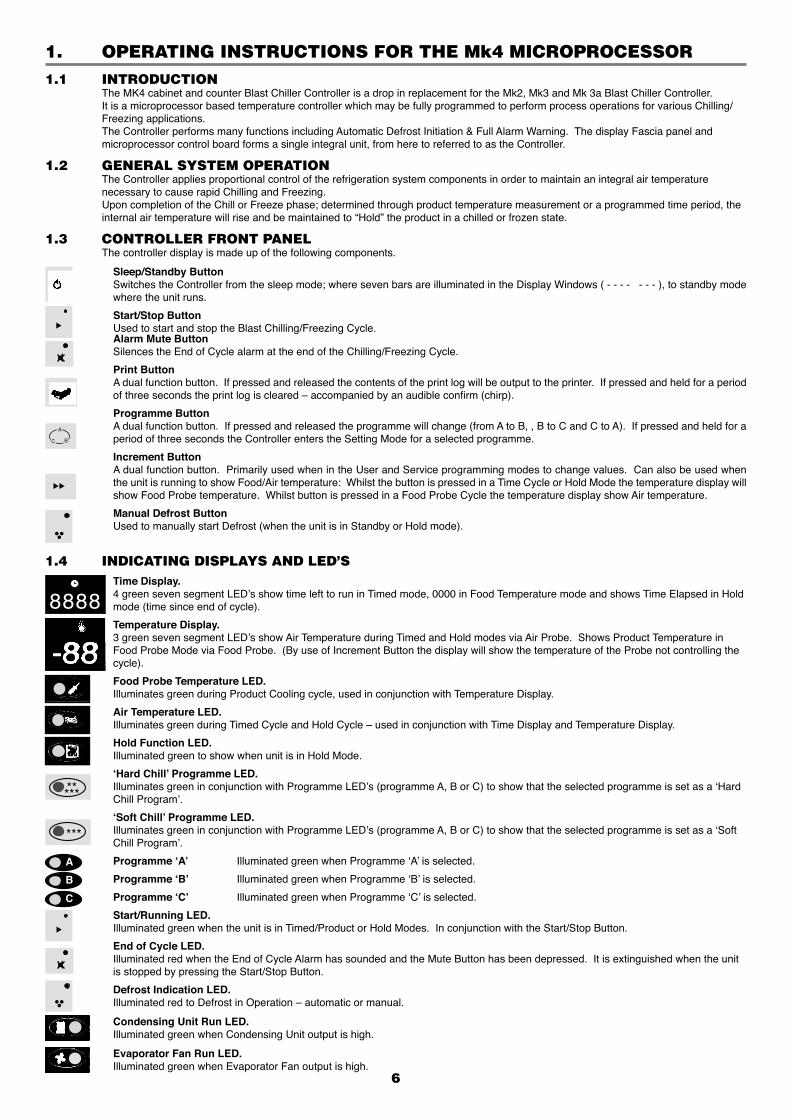
1.3 CONTROLLER FRONT PANEL The controller display is made up of the following components.
Sleep/Standby Button Switches the Controller from the sleep mode; where seven bars are illuminated in the Display Windows ( - - - - - - - ), to standby mode
where the unit runs.
Start/Stop Button Used to start and stop the Blast Chilling/Freezing Cycle. Alarm Mute Button Silences the End of Cycle alarm at the end of the Chilling/Freezing Cycle.
Print Button A dual function button. If pressed and released the contents of the print log will be output to the printer. If pressed and held for a period
of three seconds the print log is cleared – accompanied by an audible confirm (chirp).
Programme Button A dual function button. If pressed and released the programme will change (from A to B, , B to C and C to A). If pressed and held for a
period of three seconds the Controller enters the Setting Mode for a selected programme.
Increment Button A dual function button. Primarily used when in the User and Service programming modes to change values. Can also be used when
the unit is running to show Food/Air temperature: Whilst the button is pressed in a Time Cycle or Hold Mode the temperature display will show Food Probe temperature. Whilst button is pressed in a Food Probe Cycle the temperature display show Air temperature.
Manual Defrost Button Used to manually start Defrost (when the unit is in Standby or Hold mode).
A
BC
B
A
C
*****
***
1.4 INDICATING DISPLAYS AND LED’S Time Display. 4 green seven segment LED’s show time left to run in Timed mode, 0000 in Food Temperature mode and shows Time Elapsed in Hold
mode (time since end of cycle).
Temperature Display. 3 green seven segment LED’s show Air Temperature during Timed and Hold modes via Air Probe. Shows Product Temperature in
Food Probe Mode via Food Probe. (By use of Increment Button the display will show the temperature of the Probe not controlling the cycle).
Food Probe Temperature LED. Illuminates green during Product Cooling cycle, used in conjunction with Temperature Display.
Air Temperature LED. Illuminates green during Timed Cycle and Hold Cycle – used in conjunction with Time Display and Temperature Display.
Hold Function LED. Illuminated green to show when unit is in Hold Mode.
‘Hard Chill’ Programme LED. Illuminates green in conjunction with Programme LED’s (programme A, B or C) to show that the selected programme is set as a ‘Hard
Chill Program’.
‘Soft Chill’ Programme LED. Illuminates green in conjunction with Programme LED’s (programme A, B or C) to show that the selected programme is set as a ‘Soft
Chill Program’.
Programme ‘A’ Illuminated green when Programme ‘A’ is selected.
Programme ‘B’ Illuminated green when Programme ‘B’ is selected.
Programme ‘C’ Illuminated green when Programme ‘C’ is selected.
Start/Running LED. Illuminated green when the unit is in Timed/Product or Hold Modes. In conjunction with the Start/Stop Button.
End of Cycle LED. Illuminated red when the End of Cycle Alarm has sounded and the Mute Button has been depressed. It is extinguished when the unit
is stopped by pressing the Start/Stop Button.
Defrost Indication LED. Illuminated red to Defrost in Operation – automatic or manual.
Condensing Unit Run LED. Illuminated green when Condensing Unit output is high.
Evaporator Fan Run LED. Illuminated green when Evaporator Fan output is high.
-88
8888
7
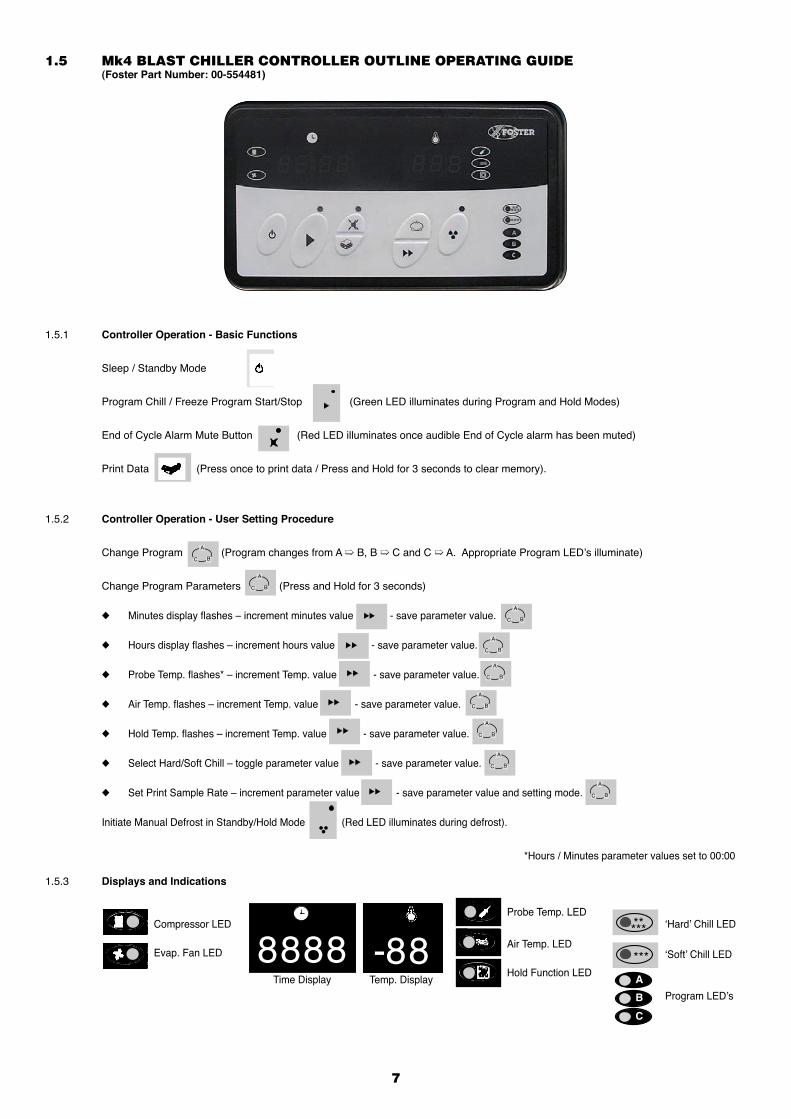
1.5 Mk4 BLAST CHILLER CONTROLLER OUTLINE OPERATING GUIDE (Foster Part Number: 00-554481)
1.5.1 Controller Operation - Basic Functions
Sleep / Standby Mode
Program Chill / Freeze Program Start/Stop (Green LED illuminates during Program and Hold Modes)
End of Cycle Alarm Mute Button (Red LED illuminates once audible End of Cycle alarm has been muted)
Print Data (Press once to print data / Press and Hold for 3 seconds to clear memory).
1.5.2 Controller Operation - User Setting Procedure
Change Program (Program changes from A ➯ B, B ➯ C and C ➯ A. Appropriate Program LED’s illuminate)
Change Program Parameters (Press and Hold for 3 seconds)
◆ Minutes display flashes – increment minutes value - save parameter value.
◆ Hours display flashes – increment hours value - save parameter value.
◆ Probe Temp. flashes* – increment Temp. value - save parameter value.
◆ Air Temp. flashes – increment Temp. value - save parameter value.
◆ Hold Temp. flashes – increment Temp. value - save parameter value.
◆ Select Hard/Soft Chill – toggle parameter value - save parameter value.
◆ Set Print Sample Rate – increment parameter value - save parameter value and setting mode.
Initiate Manual Defrost in Standby/Hold Mode (Red LED illuminates during defrost).
*Hours / Minutes parameter values set to 00:00
1.5.3 Displays and Indications
A
BC
A
BC
A
BC
A
BC
A
BC
A
BC
A
BC
A
BC
A
BC
8888*****
***
Time Display
Compressor LED
Evap. Fan LED
Probe Temp. LED
Air Temp. LED
Hold Function LED-88
Temp. Display
‘Hard’ Chill LED
‘Soft’ Chill LED
Program LED’sB
A
C
8
1.6 OPERATION1.6.1 In this section the behaviour of the Controller is described in the form of a list of events with regard to the system refrigeration
components. Where outputs are stated to be in a ‘high’ or ‘low’ state, a low state indicates the board relay output contacts to be open circuit and a
high state indicates the relay to be closed and hence ‘live’.
1.6.2 Power Connected to Unit. The Controller is in a sleep mode, seven bars are displayed on the fascia panel, all outputs are in a low state ( - - - - - - - ).
1.6.3 Sleep/Standby Button Depressed. The Controller switches on, fascia panel indicates programme, time and internal air temperature. Any one of the stored programs may
be selected by pressing the programme button. Programme settings may be altered by following the User Setting Procedure.
1.6.4 Start/Stop Button Depressed. The selected Controller programme is initiated.
1.6.5 Cooling Phase. If the selected programme is a Food Temperature Control programme, the following sequence of events will occur: The fascia panel displays Cooling Time (set to zero) and product Temperature (measured by the Food Probe). The refrigeration cycle begins and the Evaporator Fan output remains high throughout the cycle except if the door is opened. The Cooling Time displayed in the fascia panel will increment from zero. If internal air temperature is higher than the pre-set Air Temperature the Condensing Unit output goes high. When the internal air temperature pulls down to the pre-set Air Temperature the Condensing Unit output goes low. The Cooling Phase continues until the pre-set Product Temperature is reached. The end of cycle alarm sounds and the Unit enters the Hold phase (Hold LED illuminated). The displayed Cooling Time stops incrementing and holds the displayed value. The Temperature Display changes to indicate Internal Air Temperature. If the selected programme is a Cooling Time Control programme, the following sequence of events will occur: The fascia panel displays Cooling Time and Air Temperature. The refrigeration cycle begins and the Evaporator Fan output remains high throughout the cycle except if the door is opened. The Cooling Time displayed on the fascia panel will decrement from the programmed value. If internal air temperature is higher than the pre-set Air Temperature, the Condensing Unit output goes high. When the internal air temperature pulls down to the pre-set Air Temperature, the Condensing Unit output goes low. If the internal air temperature then rises above the pre-set Air Temperature plus the Differential, the Condensing Unit goes High. The Cooling time continues until the displayed time increments to zero. The end of cycle alarm sounds and the Unit enters the Hold phase (Hold LED illuminated).
1.6.6 Hold Phase. With the evaporator fan output still high, the condensing unit output falls low until the internal air temperature rises to the pre-set Hold
Temperature plus the Hold Temperature Differential. The Condensing Unit output goes high until the internal air temperature pulls down to the pre-set Hold Temperature. The Hold Phase continues until the programme is stopped by operation of the Start/stop button.
1.6.7 End of Cycle Alarm. The Controller alarm output will go high on entry to the Hold Phase to indicate completion of the Cooling Phase. The Hold Alarm will stay high for the period Hold alarm Duration. Alternatively, the Hold Alarm may be muted by operation of the fascia Mute button. However the Hold LED above the Mute button will illuminate.
1.6.8 Defrost Automatic or Manually Initiated. The time period to the first defrost is calculated from the start of the Cooling Programme. If the Defrost interval is every 4 hours but the Cooling Cycle is 6 hours the Defrost will be postponed until the Unit enters Hold Mode.
Defrosts will occur automatically in the Hold Mode. The evaporator fan output falls low. Depending on Defrost Type, either a Hot Gas (Type = 1) or Electric Heater (Type = 0) Defrost will be initiated and the Time Display will
continue to display Time Elapsed. The temperature display will show the temperature measured by the Food Probe. The RED LED will illuminate.
Alternatively, a Defrost can be initiated in the ‘Standby’ or ‘Hold’ modes. To initiate a Manual Defrost press the Defrost button once and defrost will commence. Defrost will be the same as in automatic mode.
1.7 ERROR ANNUNCIATION Should temperature probe failure occur the controller will indicate the fault by flashing on the fasica panel: PF1, PF2 or PF3 in the
temperature display window. It is important to note that on Probes 1 and 2 Probe Fault occurs if a resistance corresponding to above +60°C or below -60°C. See
page 13 for resistance values against temperature. PF1 — Indicates Food Probe failure. If a food probe fault occurs during a Food Temperature Control Programme the Condensing Unit output goes low. If a Food Probe fault occurs during a Cooling Time Programme the Controller will continue to operate normally.
PF2 — Indicates Air Probe Failure. If an Air Probe fault occurs during either a Food Temperature or Cooling Time Control Programme the Condensing Unit output goes low.
PF3 — Indicates Evaporator Coil Failure if Probe is fitted. A probe is not fitted, however in its place a 5.1 Kohm resistor is fitted. If this fails it will not effect the cooling cycle as the defrost will
terminate using the time setting.
9
1.8 HARD OR SOFT CHILL Hard/Soft Chilling is used to minimise surface damage to delicate products. The Soft Chill function raises the Air Temperature during the latter part of the Cooling Phase. The Air Temperature during the Cooling
Phase, while Soft Chill is selected, rises to the value of the Soft Chill Set Parameter temperature. Under a Cooling Time Control Programme the Soft Chill level becomes active after the percentage value of the Soft Chill Set Time
relative to the pre-set Cooling Time has lapsed. Under a Food Temperature Control Programme, the Soft Chill becomes active when the Soft Chill Food Temperature, measured by the
Food Probe is reached. Soft Chilling can only be selected if the Programme Settings — Food Temperature, Cooling Air Temperature and Hold Air Temperature
are set above the value of the Surface Protection Limit.
1.9 USER PROGRAMME SETTINGS The following is a list of the parameters that may be adjusted by the user in the programmes A, B or C.1.9.1 Cooling Time. Control Programme (Hrs : Mins). Duration of Cooling Phase for a Cooling Time Control Programme. If set to zero, the Controller automatically assumes a Food Temperature Control Programme.
1.9.2 Food temperature. Control Programme (°C). Desired Food Temperature at completion of the Cooling Phase. Required when a Food Temperature Control Programme is selected. Measured by the Food Probe inserted into the product to be cooled.
1.9.3 Cooling Air Temperature (°C). Counter or Cabinet internal air temperature during the Cooling Phase.
1.9.4 Hold Air Temperature (°C). Counter or cabinet internal air temperature during the Hold Phase.
1.9.5 Cooling Type (‘Hard’ or ‘Soft’ Chill). Selects cooling type function, which in Soft Chill raises the Air Temperature during the latter part of the Chill Phase. Soft Chill can only be selected if the Programme Settings — Food, Chill Air & Hold Air Temperature are above the value of the Soft Chill
Limit.
1.9.6 Printer Sample Rate. Selects the inteval between Air or Food temperature samples being recorded during the Cooling Cycle and Hold Mode.
1.10 PROGRAMME SETTING AND CONTROL PARAMETER ADJUSTMENT The user can tailor the Programme Settings to suit the particular product to be cooled. Settings can be saved in up to three programmes, stored by the controller (A, B or C). The Controller is pre-set with three typical programmes.
Chill Programme (P15 = 0)
ProgrammeA Programme B Programme C Time 1 Hr 30 min 0.00 Hrs 1 Hr 30 min Food Temperature Probe NA +3°C NA Air Temperature Probe -10°C -10°C -10°C Hold Temperature +3°C +3°C +3°C Chill Mode HARD HARD SOFT Print Sample Rate 3 3 3
Chill/Freeze and Freeze Programme (P15 = 1)
ProgrammeA Programme B Programme C Time 3 Hr 0.00 Hrs 1 Hr 30 min Food Temperature Probe NA -21°C NA Air Temperature Probe -30°C -30°C -10°C Hold Temperature -21°C -21°C +3°C Chill Mode HARD HARD SOFT
Print Sample Rate 3 3 3
Control Parameters alter the characteristics of the chilling or freezing process. They should not be adjusted without a good understanding of the operation of the Controller.
If no button is pressed for a period of two minutes the controller will revert to the standby mode without saving any of the modified settings.
10
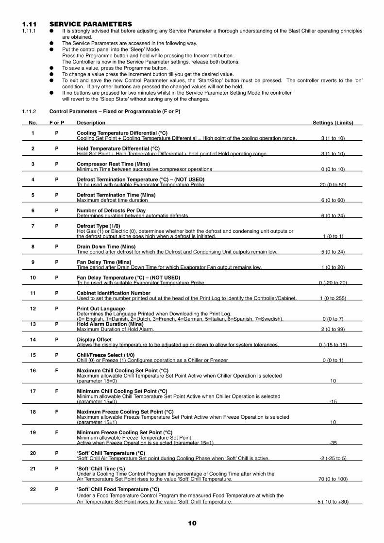
1.11 SERVICE PARAMETERS1.11.1 ● It is strongly advised that before adjusting any Service Parameter a thorough understanding of the Blast Chiller operating principles are obtained. ● The Service Parameters are accessed in the following way. ● Put the control panel into the ‘Sleep’ Mode. Press the Programme button and hold while pressing the Increment button. The Controller is now in the Service Parameter settings, release both buttons. ● To save a value, press the Programme button. ● To change a value press the Increment button till you get the desired value. ● To exit and save the new Control Parameter values, the ‘Start/Stop’ button must be pressed. The controller reverts to the ‘on’ condition. If any other buttons are pressed the changed values will not be held. ● If no buttons are pressed for two minutes whilst in the Service Parameter Setting Mode the controller will revert to the ‘Sleep State’ without saving any of the changes.
1.11.2 Control Parameters – Fixed or Programmable (F or P)
No. F or P Description Settings (Limits)
1 P Cooling Temperature Differential (°C) Cooling Set Point + Cooling Temperature Differential = High point of the cooling operation range. 3 (1 to 10)
2 P Hold Temperature Differential (°C) Hold Set Point + Hold Temperature Differential + hold point of Hold operating range. 3 (1 to 10)
3 P Compressor Rest Time (Mins) Minimum Time between successive compressor operations 0 (0 to 10)
4 P Defrost Termination Temperature (°C) – (NOT USED) To be used with suitable Evaporator Temperature Probe 20 (0 to 50)
5 P Defrost Termination Time (Mins) Maximum defrost time duration 6 (0 to 60)
6 P Number of Defrosts Per Day Determines duration between automatic defrosts 6 (0 to 24)
7 P Defrost Type (1/0) Hot Gas (1) or Electric (0), determines whether both the defrost and condensing unit outputs or the defrost output alone goes high when a defrost is initiated. 1 (0 to 1)
8 P Drain Down Time (Mins) Time period after defrost for which the Defrost and Condensing Unit outputs remain low. 5 (0 to 24)
9 P Fan Delay Time (Mins) Time period after Drain Down Time for which Evaporator Fan output remains low. 1 (0 to 20)
10 P Fan Delay Temperature (°C) – (NOT USED) To be used with suitable Evaporator Temperature Probe. 0 (-20 to 20)
11 P Cabinet Identification Number Used to set the number printed out at the head of the Print Log to identify the Controller/Cabinet. 1 (0 to 255)
12 P Print Out Language Determines the Language Printed when Downloading the Print Log. (0= English, 1=Danish, 2=Dutch, 3=French, 4=German, 5=Italian, 6=Spanish, 7=Swedish). 0 (0 to 7) 13 P Hold Alarm Duration (Mins) Maximum Duration of Hold Alarm. 2 (0 to 99)
14 P Display Offset Allows the display temperature to be adjusted up or down to allow for system tolerances. 0 (-15 to 15)
15 P Chill/Freeze Select (1/0) Chill (0) or Freeze (1) Configures operation as a Chiller or Freezer 0 (0 to 1)
16 F Maximum Chill Cooling Set Point (°C) Maximum allowable Chill Temperature Set Point Active when Chiller Operation is selected (parameter 15=0) 10
17 F Minimum Chill Cooling Set Point (°C) Minimum allowable Chill Temperature Set Point Active when Chiller Operation is selected (parameter 15=0) -15
18 F Maximum Freeze Cooling Set Point (°C) Maximum allowable Freeze Temperature Set Point Active when Freeze Operation is selected (parameter 15=1) 10
19 F Minimum Freeze Cooling Set Point (°C) Minimum allowable Freeze Temperature Set Point Active when Freeze Operation is selected (parameter 15=1) -35
20 P ‘Soft’ Chill Temperature (°C) ‘Soft’ Chill Air Temperature Set point during Cooling Phase when ‘Soft’ Chill is active. -2 (-25 to 5)
21 P ‘Soft’ Chill Time (%) Under a Cooling Time Control Program the percentage of Cooling Time after which the Air Temperature Set Point rises to the value ‘Soft’ Chill Temperature. 70 (0 to 100)
22 P ‘Soft’ Chill Food Temperature (°C) Under a Food Temperature Control Program the measured Food Temperature at which the Air Temperature Set Point rises to the value ‘Soft’ Chill Temperature. 5 (-10 to +30)
11
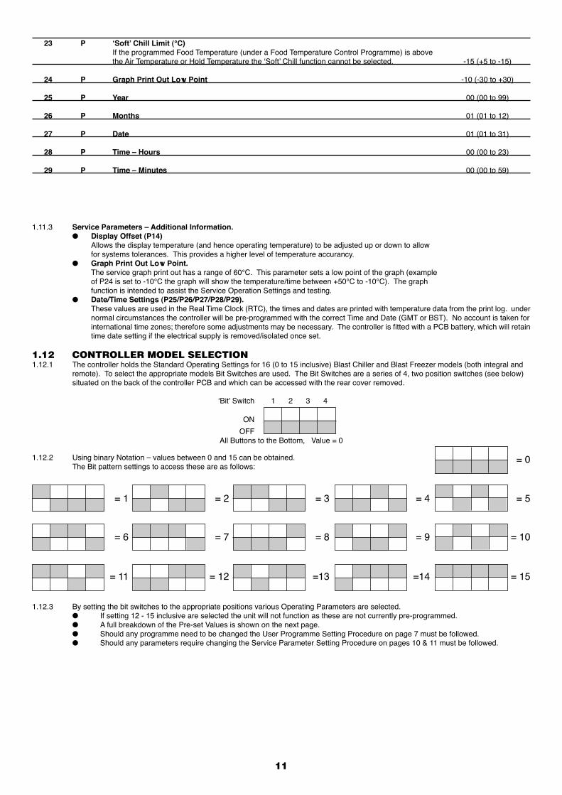
1.11.3 Service Parameters – Additional Information. ● Display Offset (P14) Allows the display temperature (and hence operating temperature) to be adjusted up or down to allow for systems tolerances. This provides a higher level of temperature accurancy. ● Graph Print Out Low Point. The service graph print out has a range of 60°C. This parameter sets a low point of the graph (example of P24 is set to -10°C the graph will show the temperature/time between +50°C to -10°C). The graph function is intended to assist the Service Operation Settings and testing. ● Date/Time Settings (P25/P26/P27/P28/P29). These values are used in the Real Time Clock (RTC), the times and dates are printed with temperature data from the print log. under normal circumstances the controller will be pre-programmed with the correct Time and Date (GMT or BST). No account is taken for
international time zones; therefore some adjustments may be necessary. The controller is fitted with a PCB battery, which will retain time date setting if the electrical supply is removed/isolated once set.
23 P ‘Soft’ Chill Limit (°C) If the programmed Food Temperature (under a Food Temperature Control Programme) is above the Air Temperature or Hold Temperature the ‘Soft’ Chill function cannot be selected. -15 (+5 to -15)
24 P Graph Print Out Low Point -10 (-30 to +30)
25 P Year 00 (00 to 99)
26 P Months 01 (01 to 12)
27 P Date 01 (01 to 31)
28 P Time – Hours 00 (00 to 23)
29 P Time – Minutes 00 (00 to 59)
1.12 CONTROLLER MODEL SELECTION1.12.1 The controller holds the Standard Operating Settings for 16 (0 to 15 inclusive) Blast Chiller and Blast Freezer models (both integral and
remote). To select the appropriate models Bit Switches are used. The Bit Switches are a series of 4, two position switches (see below) situated on the back of the controller PCB and which can be accessed with the rear cover removed.
1.12.2 Using binary Notation – values between 0 and 15 can be obtained. The Bit pattern settings to access these are as follows:
1.12.3 By setting the bit switches to the appropriate positions various Operating Parameters are selected. ● If setting 12 - 15 inclusive are selected the unit will not function as these are not currently pre-programmed. ● A full breakdown of the Pre-set Values is shown on the next page. ● Should any programme need to be changed the User Programme Setting Procedure on page 7 must be followed. ● Should any parameters require changing the Service Parameter Setting Procedure on pages 10 & 11 must be followed.
‘Bit’ Switch 1 2 3 4
ON
OFFAll Buttons to the Bottom, Value = 0
= 0
= 1 = 2 = 3 = 4 = 5
= 6 = 7 = 8 = 9 = 10
= 11 = 12 =13 =14 = 15
12
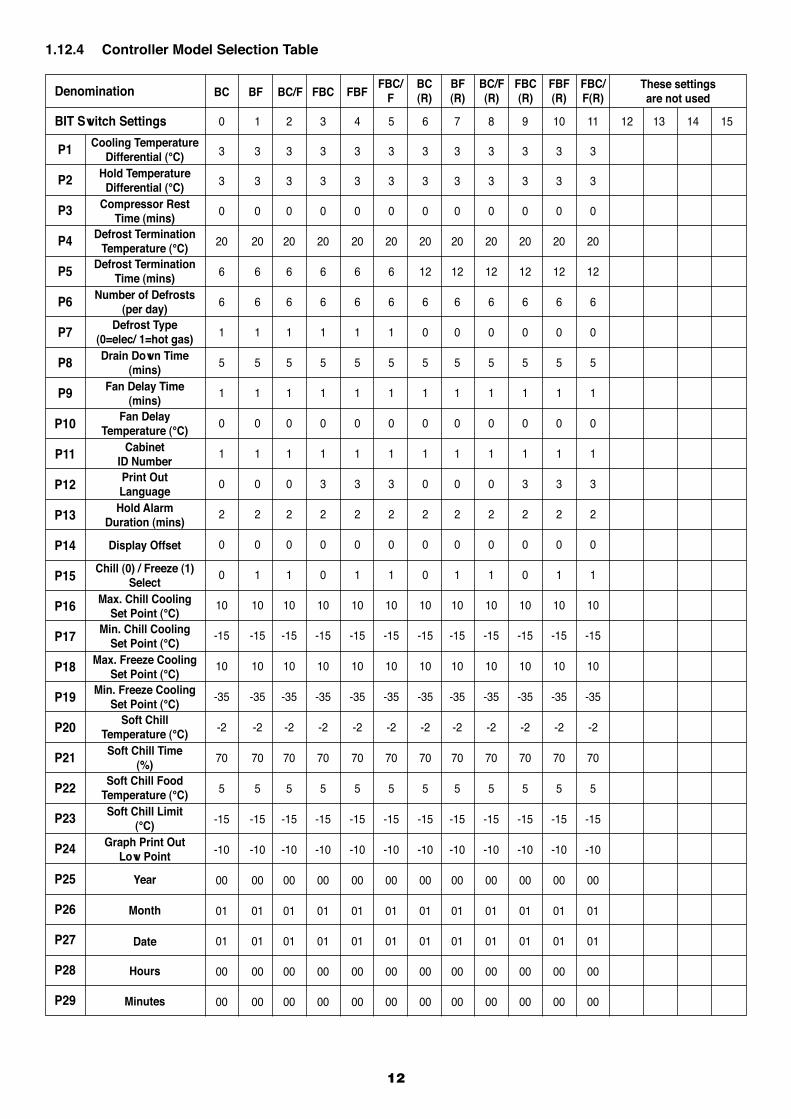
1.12.4 Controller Model Selection Table
Denomination
P1
P2
P3
P4
P5
P6
P7
P8
P9
P10
P11
P12
P13
P14
P15
P16
P17
P18
P19
P20
P21
P22
P23
P24
P25
P26
P27
P28
P29
BIT Switch Settings
Cooling Temperature Differential (°C)
Hold TemperatureDifferential (°C)
Compressor RestTime (mins)
Defrost TerminationTemperature (°C)
Defrost TerminationTime (mins)
Number of Defrosts(per day)
Defrost Type(0=elec/ 1=hot gas)Drain Down Time
(mins)Fan Delay Time
(mins)Fan Delay
Temperature (°C)Cabinet
ID NumberPrint OutLanguage
Hold AlarmDuration (mins)
Display Offset
Chill (0) / Freeze (1)Select
Max. Chill CoolingSet Point (°C)
Min. Chill CoolingSet Point (°C)
Max. Freeze CoolingSet Point (°C)
Min. Freeze CoolingSet Point (°C)
Soft ChillTemperature (°C)Soft Chill Time
(%)Soft Chill Food
Temperature (°C)Soft Chill Limit
(°C)Graph Print Out
Low Point
Year
Month
Date
Hours
Minutes
These settings are not used
FBC/F(R)
FBF(R)
FBC(R)
BC/F(R)
BF(R)
BC(R)
FBC/FFBFFBCBC/FBFBC
0 1 2 3 4 5 6 7 8 9 10 11 12 13 14 15
3 3 3 3 3 3 3 3 3 3 3 3
3 3 3 3 3 3 3 3 3 3 3 3
0 0 0 0 0 0 0 0 0 0 0 0
20 20 20 20 20 20 20 20 20 20 20 20
6 6 6 6 6 6 12 12 12 12 12 12
6 6 6 6 6 6 6 6 6 6 6 6
1 1 1 1 1 1 0 0 0 0 0 0
5 5 5 5 5 5 5 5 5 5 5 5
1 1 1 1 1 1 1 1 1 1 1 1
0 0 0 0 0 0 0 0 0 0 0 0
1 1 1 1 1 1 1 1 1 1 1 1
0 0 0 3 3 3 0 0 0 3 3 3
2 2 2 2 2 2 2 2 2 2 2 2
0 0 0 0 0 0 0 0 0 0 0 0
0 1 1 0 1 1 0 1 1 0 1 1
10 10 10 10 10 10 10 10 10 10 10 10
-15 -15 -15 -15 -15 -15 -15 -15 -15 -15 -15 -15
10 10 10 10 10 10 10 10 10 10 10 10
-35 -35 -35 -35 -35 -35 -35 -35 -35 -35 -35 -35
-2 -2 -2 -2 -2 -2 -2 -2 -2 -2 -2 -2
70 70 70 70 70 70 70 70 70 70 70 70
5 5 5 5 5 5 5 5 5 5 5 5
-15 -15 -15 -15 -15 -15 -15 -15 -15 -15 -15 -15
-10 -10 -10 -10 -10 -10 -10 -10 -10 -10 -10 -10
00 00 00 00 00 00 00 00 00 00 00 00
01 01 01 01 01 01 01 01 01 01 01 01
01 01 01 01 01 01 01 01 01 01 01 01
00 00 00 00 00 00 00 00 00 00 00 00
00 00 00 00 00 00 00 00 00 00 00 00
13
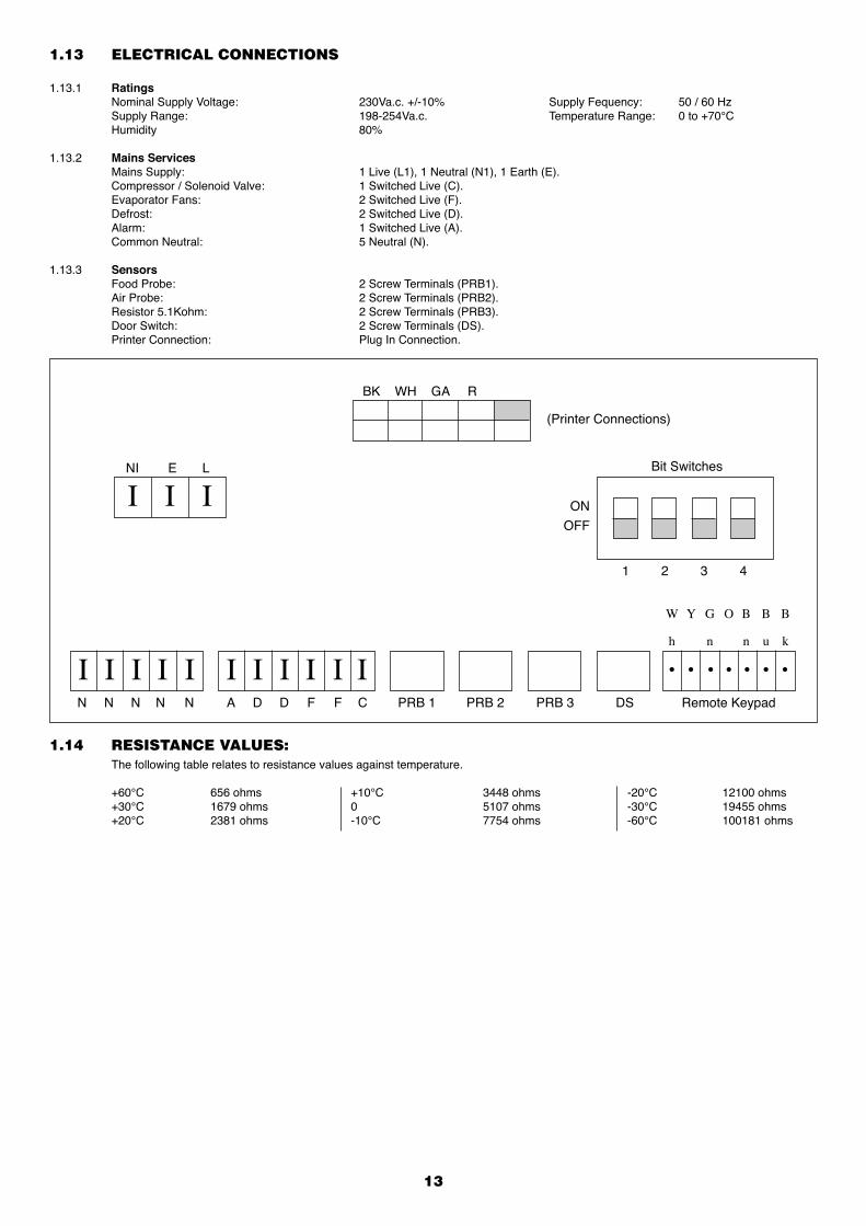
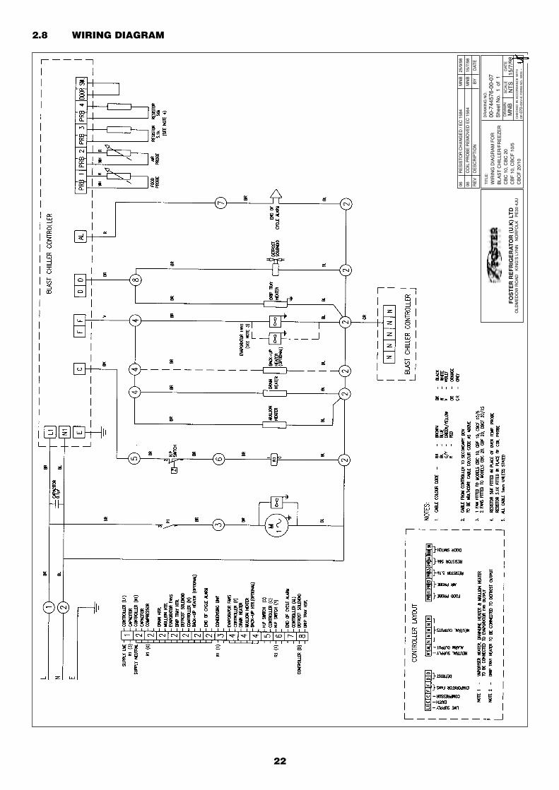
1.13 ELECTRICAL CONNECTIONS
1.13.1 Ratings Nominal Supply Voltage: 230Va.c. +/-10% Supply Fequency: 50 / 60 Hz Supply Range: 198-254Va.c. Temperature Range: 0 to +70°C Humidity 80%
1.13.2 Mains Services Mains Supply: 1 Live (L1), 1 Neutral (N1), 1 Earth (E). Compressor / Solenoid Valve: 1 Switched Live (C). Evaporator Fans: 2 Switched Live (F). Defrost: 2 Switched Live (D). Alarm: 1 Switched Live (A). Common Neutral: 5 Neutral (N).
1.13.3 Sensors Food Probe: 2 Screw Terminals (PRB1). Air Probe: 2 Screw Terminals (PRB2). Resistor 5.1Kohm: 2 Screw Terminals (PRB3). Door Switch: 2 Screw Terminals (DS). Printer Connection: Plug In Connection.
1.14 RESISTANCE VALUES: The following table relates to resistance values against temperature.
+60°C 656 ohms +10°C 3448 ohms -20°C 12100 ohms +30°C 1679 ohms 0 5107 ohms -30°C 19455 ohms +20°C 2381 ohms -10°C 7754 ohms -60°C 100181 ohms
I I I ONOFF
I II I I I II I I I
Bit Switches NI E L
(Printer Connections)
BK WH GA R
N N N N N A D D F F C PRB 1 PRB 2 PRB 3 DS Remote Keypad
• • • • • • •
h n n u k
Y OW G B B B
1 2 3 4
14
SECTION 2
Cabinet & Counter
BLAST CHILLERS & FREEZERS
15
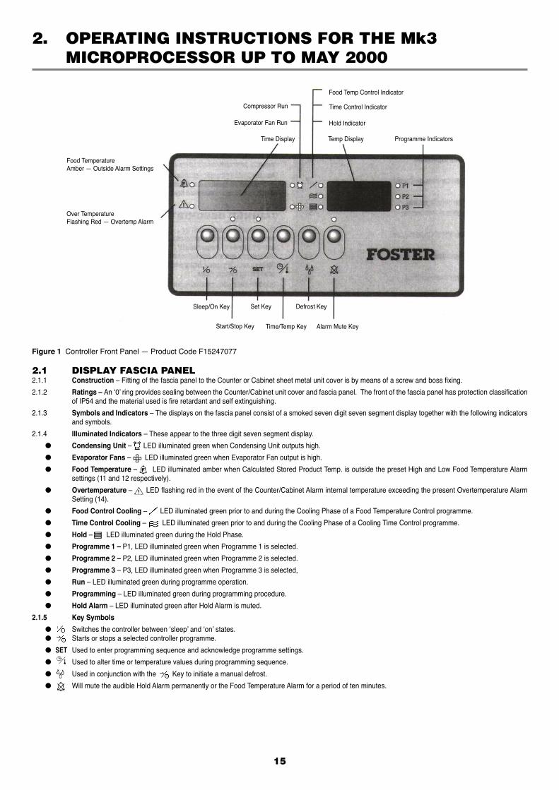
2. OPERATING INSTRUCTIONS FOR THE Mk3 MICROPROCESSOR UP TO MAY 2000
2.1 DISPLAY FASCIA PANEL2.1.1 Construction – Fitting of the fascia panel to the Counter or Cabinet sheet metal unit cover is by means of a screw and boss fixing.
2.1.2 Ratings – An ‘0’ ring provides sealing between the Counter/Cabinet unit cover and fascia panel. The front of the fascia panel has protection classification of IP54 and the material used is fire retardant and self extinguishing.
2.1.3 Symbols and Indicators – The displays on the fascia panel consist of a smoked seven digit seven segment display together with the following indicators and symbols.
2.1.4 Illuminated Indicators – These appear to the three digit seven segment display.
● Condensing Unit – LED illuminated green when Condensing Unit outputs high.
● Evaporator Fans – LED illuminated green when Evaporator Fan output is high.
● Food Temperature – LED illuminated amber when Calculated Stored Product Temp. is outside the preset High and Low Food Temperature Alarm settings (11 and 12 respectively).
● Overtemperature – LED flashing red in the event of the Counter/Cabinet Alarm internal temperature exceeding the present Overtemperature Alarm Setting (14).
● Food Control Cooling – LED illuminated green prior to and during the Cooling Phase of a Food Temperature Control programme.
● Time Control Cooling – LED illuminated green prior to and during the Cooling Phase of a Cooling Time Control programme.
● Hold – LED illuminated green during the Hold Phase.
● Programme 1 – P1, LED illuminated green when Programme 1 is selected.
● Programme 2 – P2, LED illuminated green when Programme 2 is selected.
● Programme 3 – P3, LED illuminated green when Programme 3 is selected,
● Run – LED illuminated green during programme operation.
● Programming – LED illuminated green during programming procedure.
● Hold Alarm – LED illuminated green after Hold Alarm is muted.
2.1.5 Key Symbols
● Switches the controller between ‘sleep’ and ‘on’ states. ● Starts or stops a selected controller programme.
● SET Used to enter programming sequence and acknowledge programme settings.
● Used to alter time or temperature values during programming sequence.
● Used in conjunction with the Key to initiate a manual defrost.
● Will mute the audible Hold Alarm permanently or the Food Temperature Alarm for a period of ten minutes.
Figure 1 Controller Front Panel — Product Code F15247077
Food Temp Control Indicator
Time Control Indicator
Hold Indicator
Temp Display Programme Indicators
Compressor Run
Evaporator Fan Run
Time Display
Food TemperatureAmber — Outside Alarm Settings
Over TemperatureFlashing Red — Overtemp Alarm
Sleep/On Key Set Key
Start/Stop Key Time/Temp Key Alarm Mute Key
Defrost Key
16
2.2 SURROUNDINGS AND EXTERNAL INFLUENCES2.2.1 INPUTS
● Food Temp. Probe – Senses counter/cabinet product temperature. Negative temperature/resistance coefficient thermistor probe.
● Air Temp. Probe – Senses counter/cabinet internal air temperature. Negative temperature/resistance coefficient thermistor probe.
● Evap. Temp. Probe – Senses temperature at the evaporator coil, required to terminate defrost. No longer fitted on models produced after September 1998, replaced by 5.1Kohm resistor. Defrost terminates on time only.
● Safety probe – Senses temperature adjacent to the evaporator coil in order to detect a internal overtemperature. No longer fitted on models produced after July 1998, replaced by 56Kohm resistor.
● Door Switch – Voltage free contacts, open circuit when door is open causing evaporator fan output to fall low and condensing unit output to fall low after a period of one minute.
● Display Fascia – Used to switch On/Off the controller. Initiate or terminate a chill or freeze programme. Programme in operating parameters. Manually initiate a defrost. Cancel all alarm outputs.
2.2.2 OUTPUTS
● Condensing Unit – Relay output switching single phase mains supply to condensing unit (compressor and condensor fan). Contact rating 250Vac 10A.
● Evaporator Fan – Relay output switching single phase mains supply to evaporator fan. Also, in parallel with the evaporator fan are connected the mullion and vaporiser tray heaters. Contact rating 250Vac 10A.
● Defrost – Relay output switching single phase mains supply to Hot gas solenoid or Electric heaters. Contact rating 250Vac 10A.
● External Alarm – Relay output switching single phase mains supply to alarm, activated when chill phase is completed, when calculated food temperature is outside preset limits (during hold phase) and in the event of an internal overtemperature. Contact rating 250Vac 10A.
● Display Fascia – Seven segment display, seven digets. Normally indicating cabinet air or product temperature and cooling time. To display parameter values during controller programming.
Status indication during defrost. Indicator LED’s representing correct control phase, selected programme and status of refrigeration component outputs
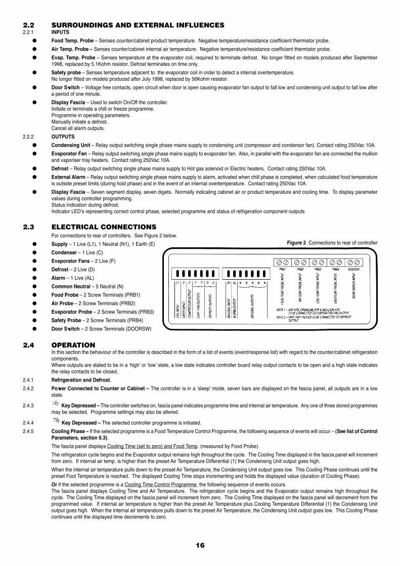
2.3 ELECTRICAL CONNECTIONS For connections to rear of controllers. See Figure 2 below.
● Supply – 1 Live (L1), 1 Neutral (N1), 1 Earth (E)
● Condenser – 1 Live (C)
● Evaporator Fans – 2 Live (F)
● Defrost – 2 Live (D)
● Alarm – 1 Live (AL)
● Common Neutral – 5 Neutral (N)
● Food Probe – 2 Screw Terminals (PRB1)
● Air Probe – 2 Screw Terminals (PRB2)
● Evaporator Probe – 2 Screw Terminals (PRB3)
● Safety Probe – 2 Screw Terminals (PRB4)
● Door Switch – 2 Screw Terminals (DOORSW)
Figure 2 Connections to rear of controller
2.4 OPERATION In this section the behaviour of the controller is described in the form of a list of events (event/response list) with regard to the counter/cabinet refrigeration
components. Where outputs are stated to be in a ‘high’ or ‘low’ state, a low state indicates controller board relay output contacts to be open and a high state indicates
the relay contacts to be closed.
2.4.1 Refrigeration and Defrost.
2.4.2 Power Connected to Counter or Cabinet – The controller is in a ‘sleep’ mode, seven bars are displayed on the fascia panel, all outputs are in a low state.
2.4.3 Key Depressed – The controller switches on, fascia panel indicates programme time and internal air temperature. Any one of three stored programmes may be selected. Programme settings may also be altered.
2.4.4 Key Depressed – The selected controller programme is initiated.
2.4.5 Cooling Phase – If the selected programme is a Food Temperature Control Programme, the folllowing sequence of events will occur – (See list of Control Parameters, section 6.3).
The fascia panel displays Cooling Time (set to zero) and Food Temp. (measured by Food Probe).
The refrigeration cycle begins and the Evaporator output remains high throughout the cycle. The Cooling Time displayed in the fascia panel will increment from zero. If internal air temp. is higher than the preset Air Temperature Differential (1) the Condensing Unit output goes high.
When the internal air temperature pulls down to the preset Air Temperature, the Condensing Unit output goes low. This Cooling Phase continues until the preset Foot Temperature is reached. The displayed Cooling Time stops incrementing and holds the displayed value (duration of Cooling Phase).
Or if the selected programme is a Cooling Time Control Programme, the following sequence of events occurs. The fascia panel displays Cooling Time and Air Temperature. The refrigeration cycle begins and the Evaporator output remains high throughout the
cycle. The Cooling Time displayed on the fascia panel will increment from zero. The Cooling Time displayed on the fascia panel will decrement from the programmed value. If internal air temperature is higher than the preset Air Temperature plus Cooling Temperature Differential (1) the Condensing Unit output goes high. When the internal air temperature pulls down to the preset Air Temperature, the Condensing Unit output goes low. This Cooling Phase continues until the displayed time decrements to zero.
17
2.4.6 Hold Phase – The Hold alarm output goes high to indicate completion of the Cooling Phase. With the evaporator fan output still high, the condensing unit output falls low until the Cabinet or Counter internal air temperature rises to the preset Hold Temperature plus Hold Temperature Differential (2). The Condensing unit output goes high until the internal air temperature pulls down to the preset Hold Temperature. The Hold Phase continues until the programme is stopped by operation of the start/stop key.
2.4.7 Time Period Elapsed Between Automatic Defrost or Manually Initiated Defrost– The time period to the first defrost is calculated from the beginning of the cycle.
The evaporator fan output falls low, depending on parameter Defrost Type (7), either a Hot Gas (Defrost Type = 1) or Electric Heater (Defrost Type = 0 defrost will be initiated and dEF will be displayed on the fascia panel.
● Hot Gas – Defrost output goes high (operating a solenoid valve) and Condensing Unit output goes high. ● Electric – Defrost output goes high (operating an electric heater) and Condensing Unit output goes low. ● When Defrost Termination Temperature (4) is reached or, Defrost Termination Time (5) has elapsed, the Defrost and Condensing Unit outputs goes low for
the Drain Down Period (8). ● The fascia panel will now display REC and the refrigeration cycle restarts, however the Evaporator Fan output will not go high until the Fan Delay Period
(9) has elapsed or the Fan Delay Temperature (10) has been reached. (Terminates on time if 5.1 kohm resistor is fitted) ● During the defrost and recovery periods, the evaporator coil temperature measured by the Evaporator Probe may be viewed by pressing the key. The refrigeration cycle will now recommence with internal air temperature displayed on the fascia.2.4.8 Alarm Functions – The Food temperature and Hold alarms may be cancelled by operation of the fascia panel alarm mute button. The internal overtemperature
alarm can only be cancelled by removing power from the controller. ● Hold Alarm – The controller alarm output will go high on entry to the Hold Phase to indicate completion of the Cooling Phase. The Hold Alarm Duration
(13). Alternatively, the Hold Alarm may be permanently muted by operation of the fascia panel key. ● Food Temperature – The controller will calculate the temperature of the stored product during the Hold Phase through monitoring internal air temperature.
Should the calculated stored product temperature fall outside the parameters High Food Temperature Alarm and Low Food Temperature Alarm (11 and 12 respectively), the Food Temperature LED will illuminate amber and the alarm output will go high. Should the stored product temperature fall back within the High and Low Food Temperature Alarm parameters the Food Temperature LED will extinguish and the alarm output will return to a low state. The Food Temperature Alarm (if in a high state) may be temporarily cancelled by operation of the fascia panel key. This will cause the alarm output to fall low for aperiod of ten minutes. If after the ten minute period, the calculated Food Temperature is still outside the preset High and Low Food Temperature Alarm Settings, the alarm output will return to a high state.
● Internal Overtemperature Alarm – Should the internal temperature rise above the parameter. Overtemperature Alarm setting (14), possibly due to a defrost heater malfunction, the Overtemperature Alarm LED will flash red and the alarm output will go high. Also at this point, all other outputs will fall low (condensing unit, evaporator fan motors and defrost). The controller will remain in an Overtemperature Alarm state until the cause is removed i.e. until the internal temperature falls below the parameter. Overtemperature Alarm Setting (14) or power is disconnected from the controller. No longer applies to models fitted with the 56Kohm resistor.
2.4.9 Programme Settings
● Cooling Time (Mins) – Duration of Cooling Phase for a Cooling Time Control Programme. If set to zero, the controller automatically assumes a Food Temperature Control Programme.
● Food Temperature (°C) – Desired Food Temperature at completion of the Cooling Phase. Required when a Food Temperature Control Programme is selected. Measured by the Food Probe inserted into the product to be cooled.
● Cooling Air Temp. (°C) – Counter or Cabinet internal air temperature during the Cooling Phase. ● Hold Air Temp. (°C) – Counter or Cabinet internal air temperature during the Hold Phase. ● Surface Protection (On/Off) – Selects Surface Protection function which raises the Air Temperature during the latter part of the Chill Phase. Surface
Protection can only be selected if the Programme Settings - Food, Chill, Air and Hold Air Temperature are above the value Surface Protection Limit (23).
2.5 ERROR ANNUNCIATION Should a temperature probe failure occur the controller will indicate the fault by flashing on the fascia panel: PF1, PF2, PF3 or PF4.
● PF1 – If a food probe fault occurs during a Food Temperature Control programme, the Condensing Unit Output will fall low. If a food probe fault occurs during a Cooling Time Control programme, the Controller will continue to operate normally. ● PF2 – If an air probe fault occurs during either a Food Temperature or Cooling Time Control Programme the condensing unit output will fall low. ● PF3 – If an evaporator probe fault occurs, the parameter Defrost Termination Temperature (4) is ignored and defrosts are caused to terminate only after
the period Defrost Termination Time (5) has elapsed. No longer applies to models fitted with the 5.1Kohm resistor, defrost is terminated by time only. ● PF4 – If a safety fault occurs, all controller outputs will fall low. (The overtemperature alarm will not sound). No longer applies to models fitted with the 56
Kohm resistor.2.5.1 Additional Features.2.5.2 Surface Protection – To minimise surface damage to delicate products, the Surface Protection function raises the Air Temperature during the latter part
of the Cooling Phase. The Air Temperature during the Cooling Phase while Surface Protection is active, rises to the value of Surface Protection Temperature (20). Under a Cooling Time Control Programme, Surface Protection Time (21) of the preset Cooling Time has elapsed. Under a Food Temperature Control Programme, Surface Protection becomes active when the value Surface Protection Food Temperature (22), measured
by the Food Probe is reached.
Surface Protection can only be selected if the Programme Settings – Food Temperature, Cooling Air Temperature and Hold Air Temperature are above the value Surface Protection Limit (23).
2.5.3 Cooling Programme Extension – During the Hold Phase following a Cooling Time Control Programme, the controller can be caused to re-enter the Cooling Phase for a further ten minutes. Programme Extension can be initiated by holding down the SET key and pressing the key.
2.5.4 Self Test Function – It is possible to cause the controller to enter a test routine during which the display outputs, relay outputs, inputs, software and software version may be checked. With power disconnected from the counter or cabinet, a jumper must be connected across the 2 ‘Test Pins’, positioned adjacent to the ‘Door Switch’ screw terminal input of the controller printed circuit board. All four temperature probes (food, air, evaporator and safety) and the door switch must be disconnected from the controller. When power is re-connected to the counter or cabinet and the controller is switched on, the test routine will be initiated. On the display fascia panel, each segment of the display and each LED indicator will illuminate in turn. Any faulty display output can be identified during this test routine.
2.5.5 Pressing the fascia panel keys will perform the tests detailed below. Note, the display will illuminate randomly during these tests (unless stated otherwise).
● If the key on the fascia panel is pressed r1 will be displayed in the right hand window of the display fascia panel and Defrost Output will go high. ● If the key on the fascia panel is pressed r2 will be displayed in the right hand window of the display fascia panel and the Evaporator Fan Output will
go high. ● If the ‘SET’ key on the fascia panel is pressed, one of the following codes will be displayed in the right hand window of the display fascia panel.
18
PAS Self Tests Passed FL1 Food Probe Fail FL2 Air Probe Fail FL3 Evaporator Probe Fail FL4 Safety Probe Fail FL5 Software Fail ● If the key on the fascia panel is pressed, the Software Version and Issue, e.g. CDO will be displayed in the right hand window of the display fascia
panel. ● If the key on the fascia panel is pressed, r3 will be displayed in the right hand window of the display fascia panel and the Condensing Unit Output will
go high. ● If the key on the fascia panel is pressed, r4 will be displayed in the right hand window of the display fascia panel and the Alarm Output will go high. ● To exit the test routine power must be disconnected from the Counter or Cabinet and the jumper removed from the ‘Test Pins’ on the controller printed
circuit board. ● If the key on the fascia panel is pressed, the Software Version and Issue, e.g. CDO will be displayed in the right hand window of the display fascia
panel. ● If the key on the fascia panel is pressed, r3 will be displayed in the right hand window of the display fascia panel and the Condensing Unit Output will
go high. ● If the key on the fascia panel is pressed, r4 will be displayed in the right hand window of the display fascia panel and the Alarm Output will go high. ● To exit the test routine power must be disconnected from the Counter or Cabinet and the jumper removed from the ‘Test Pins’ on the controller printed
circuit board.
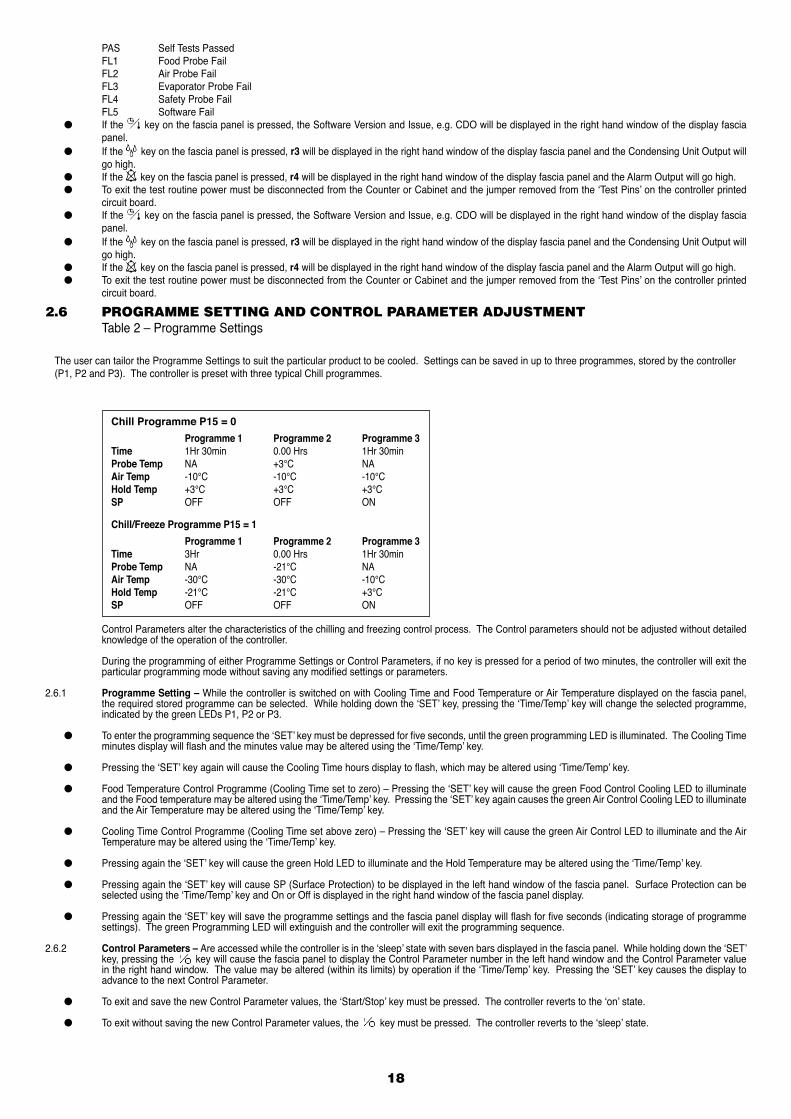
2.6 PROGRAMME SETTING AND CONTROL PARAMETER ADJUSTMENT Table 2 – Programme Settings
The user can tailor the Programme Settings to suit the particular product to be cooled. Settings can be saved in up to three programmes, stored by the controller (P1, P2 and P3). The controller is preset with three typical Chill programmes.
Control Parameters alter the characteristics of the chilling and freezing control process. The Control parameters should not be adjusted without detailed knowledge of the operation of the controller.
During the programming of either Programme Settings or Control Parameters, if no key is pressed for a period of two minutes, the controller will exit the particular programming mode without saving any modified settings or parameters.
2.6.1 Programme Setting – While the controller is switched on with Cooling Time and Food Temperature or Air Temperature displayed on the fascia panel, the required stored programme can be selected. While holding down the ‘SET’ key, pressing the ‘Time/Temp’ key will change the selected programme, indicated by the green LEDs P1, P2 or P3.
● To enter the programming sequence the ‘SET’ key must be depressed for five seconds, until the green programming LED is illuminated. The Cooling Time minutes display will flash and the minutes value may be altered using the ‘Time/Temp’ key.
● Pressing the ‘SET’ key again will cause the Cooling Time hours display to flash, which may be altered using ‘Time/Temp’ key.
● Food Temperature Control Programme (Cooling Time set to zero) – Pressing the ‘SET’ key will cause the green Food Control Cooling LED to illuminate and the Food temperature may be altered using the ‘Time/Temp’ key. Pressing the ‘SET’ key again causes the green Air Control Cooling LED to illuminate and the Air Temperature may be altered using the ‘Time/Temp’ key.
● Cooling Time Control Programme (Cooling Time set above zero) – Pressing the ‘SET’ key will cause the green Air Control LED to illuminate and the Air Temperature may be altered using the ‘Time/Temp’ key.
● Pressing again the ‘SET’ key will cause the green Hold LED to illuminate and the Hold Temperature may be altered using the ‘Time/Temp’ key.
● Pressing again the ‘SET’ key will cause SP (Surface Protection) to be displayed in the left hand window of the fascia panel. Surface Protection can be selected using the ‘Time/Temp’ key and On or Off is displayed in the right hand window of the fascia panel display.
● Pressing again the ‘SET’ key will save the programme settings and the fascia panel display will flash for five seconds (indicating storage of programme settings). The green Programming LED will extinguish and the controller will exit the programming sequence.
2.6.2 Control Parameters – Are accessed while the controller is in the ‘sleep’ state with seven bars displayed in the fascia panel. While holding down the ‘SET’ key, pressing the key will cause the fascia panel to display the Control Parameter number in the left hand window and the Control Parameter value in the right hand window. The value may be altered (within its limits) by operation if the ‘Time/Temp’ key. Pressing the ‘SET’ key causes the display to advance to the next Control Parameter.
● To exit and save the new Control Parameter values, the ‘Start/Stop’ key must be pressed. The controller reverts to the ‘on’ state.
● To exit without saving the new Control Parameter values, the key must be pressed. The controller reverts to the ‘sleep’ state.
Chill Programme P15 = 0
Programme 1 Programme 2 Programme 3 Time 1Hr 30min 0.00 Hrs 1Hr 30min Probe Temp NA +3°C NA Air Temp -10°C -10°C -10°C Hold Temp +3°C +3°C +3°C SP OFF OFF ON
Chill/Freeze Programme P15 = 1
Programme 1 Programme 2 Programme 3 Time 3Hr 0.00 Hrs 1Hr 30min Probe Temp NA -21°C NA Air Temp -30°C -30°C -10°C Hold Temp -21°C -21°C +3°C SP OFF OFF ON
19
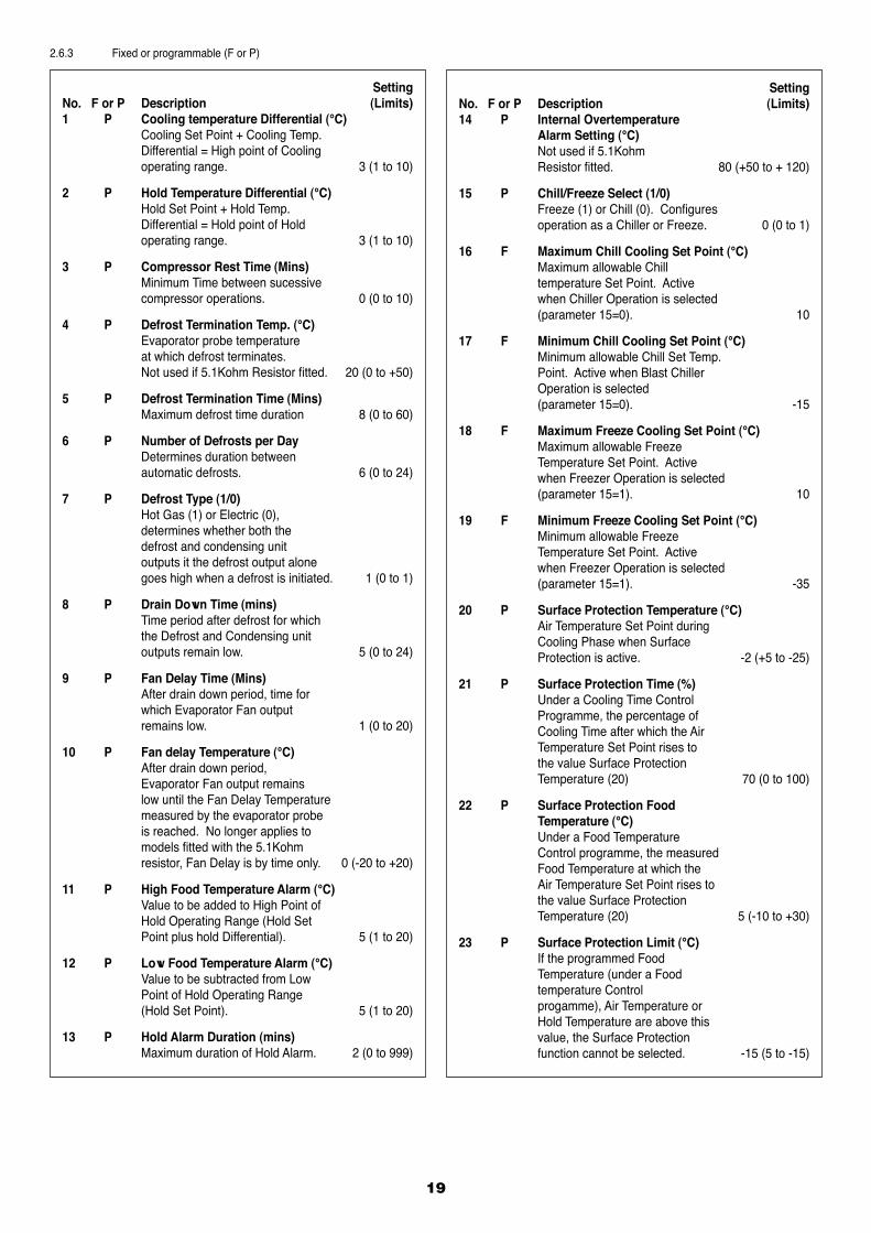
2.6.3 Fixed or programmable (F or P)
SettingNo. F or P Description (Limits)1 P Cooling temperature Differential (°C) Cooling Set Point + Cooling Temp. Differential = High point of Cooling operating range. 3 (1 to 10)
2 P Hold Temperature Differential (°C) Hold Set Point + Hold Temp. Differential = Hold point of Hold operating range. 3 (1 to 10)
3 P Compressor Rest Time (Mins) Minimum Time between sucessive compressor operations. 0 (0 to 10)
4 P Defrost Termination Temp. (°C) Evaporator probe temperature at which defrost terminates. Not used if 5.1Kohm Resistor fitted. 20 (0 to +50)
5 P Defrost Termination Time (Mins) Maximum defrost time duration 8 (0 to 60)
6 P Number of Defrosts per Day Determines duration between automatic defrosts. 6 (0 to 24)
7 P Defrost Type (1/0) Hot Gas (1) or Electric (0), determines whether both the defrost and condensing unit outputs it the defrost output alone goes high when a defrost is initiated. 1 (0 to 1)
8 P Drain Down Time (mins) Time period after defrost for which the Defrost and Condensing unit outputs remain low. 5 (0 to 24)
9 P Fan Delay Time (Mins) After drain down period, time for which Evaporator Fan output remains low. 1 (0 to 20)
10 P Fan delay Temperature (°C) After drain down period, Evaporator Fan output remains low until the Fan Delay Temperature measured by the evaporator probe is reached. No longer applies to models fitted with the 5.1Kohm resistor, Fan Delay is by time only. 0 (-20 to +20)
11 P High Food Temperature Alarm (°C) Value to be added to High Point of Hold Operating Range (Hold Set Point plus hold Differential). 5 (1 to 20)
12 P Low Food Temperature Alarm (°C) Value to be subtracted from Low Point of Hold Operating Range (Hold Set Point). 5 (1 to 20)
13 P Hold Alarm Duration (mins) Maximum duration of Hold Alarm. 2 (0 to 999)
SettingNo. F or P Description (Limits)14 P Internal Overtemperature Alarm Setting (°C) Not used if 5.1Kohm Resistor fitted. 80 (+50 to + 120)
15 P Chill/Freeze Select (1/0) Freeze (1) or Chill (0). Configures operation as a Chiller or Freeze. 0 (0 to 1)
16 F Maximum Chill Cooling Set Point (°C) Maximum allowable Chill temperature Set Point. Active when Chiller Operation is selected (parameter 15=0). 10
17 F Minimum Chill Cooling Set Point (°C) Minimum allowable Chill Set Temp. Point. Active when Blast Chiller Operation is selected (parameter 15=0). -15
18 F Maximum Freeze Cooling Set Point (°C) Maximum allowable Freeze Temperature Set Point. Active when Freezer Operation is selected (parameter 15=1). 10
19 F Minimum Freeze Cooling Set Point (°C) Minimum allowable Freeze Temperature Set Point. Active when Freezer Operation is selected (parameter 15=1). -35
20 P Surface Protection Temperature (°C) Air Temperature Set Point during Cooling Phase when Surface Protection is active. -2 (+5 to -25)
21 P Surface Protection Time (%) Under a Cooling Time Control Programme, the percentage of Cooling Time after which the Air Temperature Set Point rises to the value Surface Protection Temperature (20) 70 (0 to 100)
22 P Surface Protection Food Temperature (°C) Under a Food Temperature Control programme, the measured Food Temperature at which the Air Temperature Set Point rises to the value Surface Protection Temperature (20) 5 (-10 to +30)
23 P Surface Protection Limit (°C) If the programmed Food Temperature (under a Food temperature Control progamme), Air Temperature or Hold Temperature are above this value, the Surface Protection function cannot be selected. -15 (5 to -15)
20
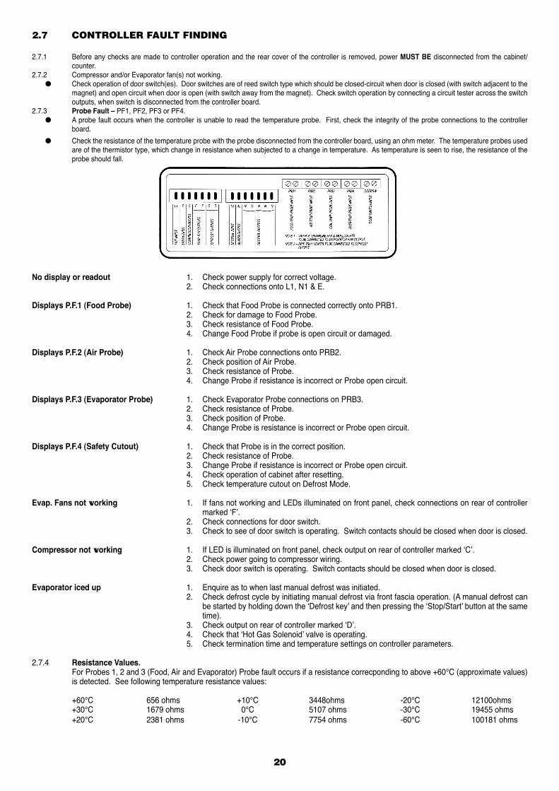
2.7 CONTROLLER FAULT FINDING
2.7.1 Before any checks are made to controller operation and the rear cover of the controller is removed, power MUST BE disconnected from the cabinet/counter.
2.7.2 Compressor and/or Evaporator fan(s) not working. ● Check operation of door switch(es). Door switches are of reed switch type which should be closed-circuit when door is closed (with switch adjacent to the
magnet) and open circuit when door is open (with switch away from the magnet). Check switch operation by connecting a circuit tester across the switch outputs, when switch is disconnected from the controller board.
2.7.3 Probe Fault – PF1, PF2, PF3 or PF4. ● A probe fault occurs when the controller is unable to read the temperature probe. First, check the integrity of the probe connections to the controller
board.
● Check the resistance of the temperature probe with the probe disconnected from the controller board, using an ohm meter. The temperature probes used are of the thermistor type, which change in resistance when subjected to a change in temperature. As temperature is seen to rise, the resistance of the probe should fall.
No display or readout 1. Check power supply for correct voltage. 2. Check connections onto L1, N1 & E.
Displays P.F.1 (Food Probe) 1. Check that Food Probe is connected correctly onto PRB1. 2. Check for damage to Food Probe. 3. Check resistance of Food Probe. 4. Change Food Probe if probe is open circuit or damaged.
Displays P.F.2 (Air Probe) 1. Check Air Probe connections onto PRB2. 2. Check position of Air Probe. 3. Check resistance of Probe. 4. Change Probe if resistance is incorrect or Probe open circuit.
Displays P.F.3 (Evaporator Probe) 1. Check Evaporator Probe connections on PRB3. 2. Check resistance of Probe. 3. Check position of Probe. 4. Change Probe is resistance is incorrect or Probe open circuit.
Displays P.F.4 (Safety Cutout) 1. Check that Probe is in the correct position. 2. Check resistance of Probe. 3. Change Probe if resistance is incorrect or Probe open circuit. 4. Check operation of cabinet after resetting. 5. Check temperature cutout on Defrost Mode.
Evap. Fans not working 1. If fans not working and LEDs illuminated on front panel, check connections on rear of controller marked ‘F’.
2. Check connections for door switch. 3. Check to see of door switch is operating. Switch contacts should be closed when door is closed.
Compressor not working 1. If LED is illuminated on front panel, check output on rear of controller marked ‘C’. 2. Check power going to compressor wiring. 3. Check door switch is operating. Switch contacts should be closed when door is closed.
Evaporator iced up 1. Enquire as to when last manual defrost was initiated. 2. Check defrost cycle by initiating manual defrost via front fascia operation. (A manual defrost can
be started by holding down the ‘Defrost key’ and then pressing the ‘Stop/Start’ button at the same time).
3. Check output on rear of controller marked ‘D’. 4. Check that ‘Hot Gas Solenoid’ valve is operating. 5. Check termination time and temperature settings on controller parameters.
2.7.4 Resistance Values. For Probes 1, 2 and 3 (Food, Air and Evaporator) Probe fault occurs if a resistance correcponding to above +60°C (approximate values)
is detected. See following temperature resistance values:
+60°C 656 ohms +10°C 3448ohms -20°C 12100ohms +30°C 1679 ohms 0°C 5107 ohms -30°C 19455 ohms +20°C 2381 ohms -10°C 7754 ohms -60°C 100181 ohms
21
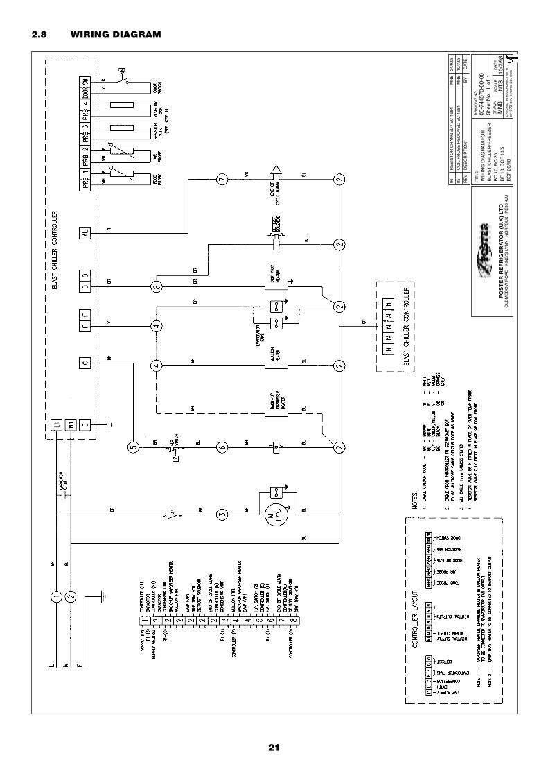
2.8 WIRING DIAGRAM
DR
AW
ING
NO
.
00-7
4457
0-00
-06
She
et N
o. 1
of
1D
RA
WN
MN
BS
CA
LEN
TS
DAT
E10
/7/9
8C
HE
CK
ED IN
AC
CO
RD
AN
CE W
ITH
OF-0
70-D
EV-E
FO
RM
NO. W
DS -
FO
ST
ER
RE
FR
IGE
RA
TOR
(U
.K)
LTD
OLD
ME
DO
W R
OA
D
KIN
G’S
LY
NN
N
OR
FO
LK
PE
30 4
JU
TIT
LE:
WIR
ING
DIA
GR
AM
FO
R
BLA
ST
CH
ILLE
R/F
RE
EZ
ER
BC
10,
BC
20
BF
10,
BC
F 1
0/5
BC
F 2
0/10
06
RE
SIS
TOR
CH
AN
GE
D /
EC
158
4 M
NB
24
/9/9
8
05
CO
IL P
RO
BE
RE
MO
VE
D E
C 1
564
MN
B
10/7
/98
RE
V
DE
SC
RIP
TIO
N
BY
D
ATE
22
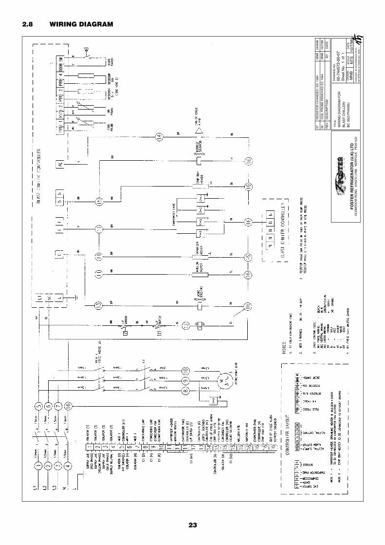
2.8 WIRING DIAGRAM
DR
AW
ING
NO
.
00-7
4457
6-00
-07
She
et N
o. 1
of
1D
RA
WN
MN
BS
CA
LEN
TS
DAT
E15
/7/9
8C
HE
CK
ED IN
AC
CO
RD
AN
CE W
ITH
OF-0
70-D
EV-E
FO
RM
NO. W
DS -
FO
ST
ER
RE
FR
IGE
RA
TOR
(U
.K)
LTD
OLD
ME
DO
W R
OA
D
KIN
G’S
LY
NN
N
OR
FO
LK
PE
30 4
JU
TIT
LE:
WIR
ING
DIA
GR
AM
FO
R
BLA
ST
CH
ILLE
R/F
RE
EZ
ER
CB
C 1
0, C
BC
20
CB
F 1
0, C
BC
F 1
0/5
CB
CF
20/
10
06
RE
SIS
TOR
CH
AN
GE
D /
EC
158
4 M
NB
25
/9/9
8
06
CO
IL P
RO
BE
RE
MO
VE
D E
C 1
564
MN
B
15/7
/98
RE
V
DE
SC
RIP
TIO
N
BY
D
ATE
23
2.8 WIRING DIAGRAM
DR
AW
ING
NO
.
00-7
4457
2-00
-07
She
et N
o. 1
of
1D
RA
WN
MN
BS
CA
LEN
TS
DAT
E10
/7/9
8C
HE
CK
ED IN
AC
CO
RD
AN
CE W
ITH
OF-0
70-D
EV-E
FO
RM
NO. W
DS -
FO
ST
ER
RE
FR
IGE
RA
TOR
(U
.K)
LTD
OLD
ME
DO
W R
OA
D
KIN
G’S
LY
NN
N
OR
FO
LK
PE
30 4
JU
TIT
LE:
WIR
ING
DIA
GR
AM
FO
R
BLA
ST
CH
ILLE
R/
BC
35(
3 P
HA
SE
)
07
RE
SIS
TOR
CH
AN
GE
D /
EC
158
4 M
NB
24
/9/9
8
06
CO
IL P
RO
BE
RE
MO
VE
D E
C 1
564
MN
B
10/7
/98
RE
V
DE
SC
RIP
TIO
N
BY
D
ATE
SECTION 3
ModularBLAST CHILLERS
& FREEZERS
24
25
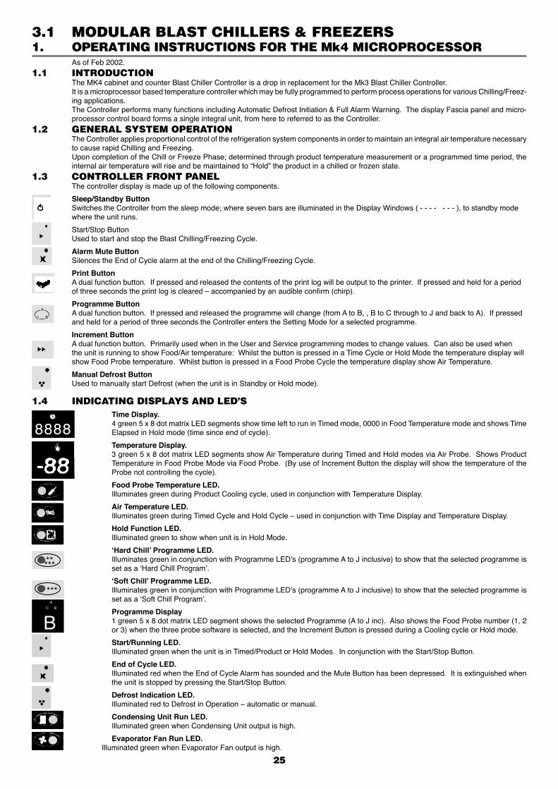
1. OPERATING INSTRUCTIONS FOR THE Mk4 MICROPROCESSOR
As of Feb 2002.1.1 INTRODUCTION The MK4 cabinet and counter Blast Chiller Controller is a drop in replacement for the Mk3 Blast Chiller Controller. It is a microprocessor based temperature controller which may be fully programmed to perform process operations for various Chilling/Freez-
ing applications. The Controller performs many functions including Automatic Defrost Initiation & Full Alarm Warning. The display Fascia panel and micro-
processor control board forms a single integral unit, from here to referred to as the Controller.1.2 GENERAL SYSTEM OPERATION The Controller applies proportional control of the refrigeration system components in order to maintain an integral air temperature necessary
to cause rapid Chilling and Freezing. Upon completion of the Chill or Freeze Phase; determined through product temperature measurement or a programmed time period, the
internal air temperature will rise and be maintained to “Hold” the product in a chilled or frozen state.1.3 CONTROLLER FRONT PANEL The controller display is made up of the following components.
Sleep/Standby Button Switches the Controller from the sleep mode; where seven bars are illuminated in the Display Windows ( - - - - - - - ), to standby mode
where the unit runs.
Start/Stop Button Used to start and stop the Blast Chilling/Freezing Cycle.
Alarm Mute Button Silences the End of Cycle alarm at the end of the Chilling/Freezing Cycle.
Print Button A dual function button. If pressed and released the contents of the print log will be output to the printer. If pressed and held for a period
of three seconds the print log is cleared – accompanied by an audible confirm (chirp).
Programme Button A dual function button. If pressed and released the programme will change (from A to B, , B to C through to J and back to A). If pressed
and held for a period of three seconds the Controller enters the Setting Mode for a selected programme.
Increment Button A dual function button. Primarily used when in the User and Service programming modes to change values. Can also be used when
the unit is running to show Food/Air temperature: Whilst the button is pressed in a Time Cycle or Hold Mode the temperature display will show Food Probe temperature. Whilst button is pressed in a Food Probe Cycle the temperature display show Air Temperature.
Manual Defrost Button Used to manually start Defrost (when the unit is in Standby or Hold mode).
A
BC
1.4 INDICATING DISPLAYS AND LED’S
Time Display. 4 green 5 x 8 dot matrix LED segments show time left to run in Timed mode, 0000 in Food Temperature mode and shows Time
Elapsed in Hold mode (time since end of cycle).
Temperature Display. 3 green 5 x 8 dot matrix LED segments show Air Temperature during Timed and Hold modes via Air Probe. Shows Product
Temperature in Food Probe Mode via Food Probe. (By use of Increment Button the display will show the temperature of the Probe not controlling the cycle).
Food Probe Temperature LED. Illuminates green during Product Cooling cycle, used in conjunction with Temperature Display.
Air Temperature LED. Illuminates green during Timed Cycle and Hold Cycle – used in conjunction with Time Display and Temperature Display.
Hold Function LED. Illuminated green to show when unit is in Hold Mode.
‘Hard Chill’ Programme LED. Illuminates green in conjunction with Programme LED’s (programme A to J inclusive) to show that the selected programme is
set as a ‘Hard Chill Program’.
‘Soft Chill’ Programme LED. Illuminates green in conjunction with Programme LED’s (programme A to J inclusive) to show that the selected programme is
set as a ‘Soft Chill Program’.
Programme Display 1 green 5 x 8 dot matrix LED segment shows the selected Programme (A to J inc). Also shows the Food Probe number (1, 2
or 3) when the three probe software is selected, and the Increment Button is pressed during a Cooling cycle or Hold mode.
Start/Running LED. Illuminated green when the unit is in Timed/Product or Hold Modes. In conjunction with the Start/Stop Button.
End of Cycle LED. Illuminated red when the End of Cycle Alarm has sounded and the Mute Button has been depressed. It is extinguished when
the unit is stopped by pressing the Start/Stop Button.
Defrost Indication LED. Illuminated red to Defrost in Operation – automatic or manual.
Condensing Unit Run LED. Illuminated green when Condensing Unit output is high.
Evaporator Fan Run LED. Illuminated green when Evaporator Fan output is high.
*****
***
-88
8888
C BA
B
3.1 MODULAR BLAST CHILLERS & FREEZERS
PROCEDURE FOR MODIFYING MODULAR BLAST CHILLER FROM ELM MK3/3A (ELM) CONTROLLER TO SUIT MK4 (ELM) CONTROLLER
The MK4 controller is interchangeable with theMk3/3A controller but care will need to be taken when connecting as the terminals on the Mk 4 controller are arranged differently but marked in the same way, with the exception of the Capacity control which is marked as ‘P’ Whereas previously it was marked as ‘Cap’
The probes are arranged differently, with the exception of the over temp probe which is not required with the Mk4 control system.
For wiring detail consult Sheet 4 of Wiring Diagram 00-838137-00-07 and follow the instructions below :
I ) Connect the Food probe to terminals 37& 38 on the Control panel terminal rail. Connect controller/terminal rail interconnecting loom terminals Red and White cores to terminals 37& 38 and Probe 1 on the controller.
2) Connect the Air probe to terminals 39 & 40 on the Control panel terminal rail. Connect controller/terminal rail interconnecting loom terminbals Yellow and Blue cores to terminals 39 & 40 and probe 2 on the controller.
3) Connect the Coil probe to terminals 41 & 42 on the control panel terminal rail. Connect controller /terminal rail interconnecting loom terminals Black & Grey cores to terminals 41 & 42 and probe 3 on the controller.
26
27
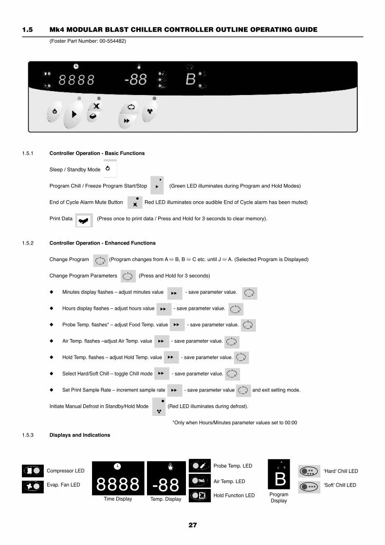
1.5 Mk4 MODULAR BLAST CHILLER CONTROLLER OUTLINE OPERATING GUIDE
(Foster Part Number: 00-554482)
1.5.1 Controller Operation - Basic Functions
Sleep / Standby Mode
Program Chill / Freeze Program Start/Stop (Green LED illuminates during Program and Hold Modes)
End of Cycle Alarm Mute Button Red LED illuminates once audible End of Cycle alarm has been muted)
Print Data (Press once to print data / Press and Hold for 3 seconds to clear memory).
1.5.2 Controller Operation - Enhanced Functions
Change Program (Program changes from A ➯ B, B ➯ C etc. until J ➯ A. (Selected Program is Displayed)
Change Program Parameters (Press and Hold for 3 seconds)
◆ Minutes display flashes – adjust minutes value - save parameter value.
◆ Hours display flashes – adjust hours value - save parameter value.
◆ Probe Temp. flashes* – adjust Food Temp. value - save parameter value.
◆ Air Temp. flashes –adjust Air Temp. value - save parameter value.
◆ Hold Temp. flashes – adjust Hold Temp. value - save parameter value.
◆ Select Hard/Soft Chill – toggle Chill mode - save parameter value.
◆ Set Print Sample Rate – increment sample rate - save parameter value and exit setting mode.
Initiate Manual Defrost in Standby/Hold Mode (Red LED illuminates during defrost).
*Only when Hours/Minutes parameter values set to 00:00
1.5.3 Displays and Indications
A
BC
A
BC
A
BC
A
BC
A
BC
A
BC
A
BC
A
BC
A
BC
8888*****
***
Time Display
Compressor LED
Evap. Fan LED
Probe Temp. LED
Air Temp. LED
Hold Function LED-88
Temp. Display
‘Hard’ Chill LED
‘Soft’ Chill LED
A
BC
BProgramDisplay
28
1.6 OPERATION1.6.1 In this section the behaviour of the Controller is described in the form of a list of events with regard to the system refrigeration
components. Where outputs are stated to be in a ‘high’ or ‘low’ state, a low state indicates the board relay output contacts to be open circuit and a
high state indicates the relay to be closed and hence ‘live’.1.6.2 Power Connected to Unit. The Controller is in a sleep mode, seven bars are displayed on the fascia panel, all outputs are in a low state ( - - - - - - - ).1.6.3 Sleep/Standby Button Depressed. The Controller switches on, fascia panel indicates programme, time and internal air temperature. Any one of the stored programs may
be selected by pressing the programme button. Programme settings may be altered by following the User Setting Procedure.1.6.4 Start/Stop Button Depressed. The selected Controller programme is initiated.1.6.5 Cooling Phase. If the selected programme is a Food Temperature Control programme, the following sequence of events will occur: The fascia panel displays Cooling Time (set to zero) and product Temperature (measured by the Food Probe). The refrigeration cycle begins and the Evaporator Fan output remains high throughout the cycle except if the door is opened. The Cooling Time displayed in the fascia panel will increment from zero. If internal air temperature is higher than the pre-set Air Temperature the Condensing Unit output goes high. When the internal air temperature pulls down to the pre-set Air Temperature the Condensing Unit output goes low. The Cooling Phase continues until the pre-set Product Temperature is reached. The end of cycle alarm sounds and the Unit enters the Hold phase (Hold LED illuminated). The displayed Cooling Time stops incrementing and holds the displayed value. The Temperature Display changes to indicate Internal Air Temperature. If the selected programme is a Cooling Time Control programme, the following sequence of events will occur: The fascia panel displays Cooling Time and Air Temperature. The refrigeration cycle begins and the Evaporator Fan output remains high throughout the cycle except if the door is opened. The Cooling Time displayed on the fascia panel will decrement from the programmed value. If internal air temperature is higher than the pre-set Air Temperature, the Condensing Unit output goes high. When the internal air temperature pulls down to the pre-set Air Temperature, the Condensing Unit output goes low. If the internal air temperature then rises above the pre-set Air Temperature plus the Differential, the Condensing Unit goes High. The Cooling time continues until the displayed time increments to zero. The end of cycle alarm sounds and the Unit enters the Hold phase (Hold LED illuminated).1.6.6 Hold Phase. With the evaporator fan output still high, the condensing unit output falls low until the internal air temperature rises to the pre-set Hold
Temperature plus the Hold Temperature Differential. The Condensing Unit output goes high until the internal air temperature pulls down to the pre-set Hold Temperature. The Hold Phase continues until the programme is stopped by operation of the Start/stop button.1.6.7 End of Cycle Alarm. The Controller alarm output will go high on entry to the Hold Phase to indicate completion of the Cooling Phase. The Hold Alarm will stay high for the period Hold alarm Duration. Alternatively, the Hold Alarm may be muted by operation of the fascia Mute button. However the Hold LED above the Mute button will illuminate.1.6.8 Defrost Automatic or Manually Initiated. The time period to the first defrost is calculated from the start of the Cooling Programme. If the Defrost interval is every 4 hours but the Cooling Cycle is 6 hours the Defrost will be postponed until the Unit enters Hold Mode.
Defrosts will occur automatically in the Hold Mode. The evaporator fan output falls low. Depending on Defrost Type, either a Hot Gas (Type = 1) or Electric Heater (Type = 0) Defrost will be initiated and the Time Display will
continue to display Time Elapsed. The temperature display will show the temperature measured by the Food Probe. The RED LED will illuminate.
Alternatively, a Defrost can be initiated in the ‘Standby’ or ‘Hold’ modes. To initiate a Manual Defrost press the Defrost button once and defrost will commence. Defrost will be the same as in automatic mode.
1.7 ERROR ANNUNCIATION Should temperature probe failure occur the controller will indicate the fault by flashing on the fasica panel: PF1, PF2, PF3, PF4 or PF5 in
the temperature display window. It is important to note that on Probes 1 and 2 Probe Fault occurs if a resistance corresponding to above +60°C or below -60°C. See
page 33 for resistance values against temperature.PF1 — Indicates Food Probe failure. If a food probe fault occurs during a Food Temperature Control Programme the Condensing Unit output goes low. If a Food Probe fault occurs during a Cooling Time Programme the Controller will continue to operate normally.PF2 — Indicates Air Probe Failure. If an Air Probe fault occurs during either a Food Temperature or Cooling Time Control Programme the Condensing
Unit output goes low.PF3 — Indicates Evaporator Coil Failure. A probe is not fitted, however in its place a 5.1 Kohm resistor is fitted. If this fails it will not effect the cooling cycle as
the defrost will terminate using the time setting.PF4 &PF5 — Indicates Food Probe 2 & 3 Failures respectively. Displayed only in standby mode, this fault will only register if the probe software is activated. Theres is no effect on
unit operation or programming.
29
1.8 HARD OR SOFT CHILL Hard/Soft Chilling is used to minimise surface damage to delicate products. The Soft Chill function raises the Air Temperature during the latter part of the Cooling Phase. The Air Temperature during the Cooling
Phase, while Soft Chill is selected, rises to the value of the Soft Chill Set Parameter temperature. Under a Cooling Time Control Programme the Soft Chill level becomes active after the percentage value of the Soft Chill Set Time
relative to the pre-set Cooling Time has lapsed. Under a Food Temperature Control Programme, the Soft Chill becomes active when the Soft Chill Food Temperature, measured by the
Food Probe is reached. Soft Chilling can only be selected if the Programme Settings — Food Temperature, Cooling Air Temperature and Hold Air Temperature
are set above the value of the Surface Protection Limit.
1.9 USER PROGRAMME SETTINGS The following is a list of the parameters that may be adjusted by the user in the programmes A to J.1.9.1 Cooling Time. Control Programme (Hrs : Mins). Duration of Cooling Phase for a Cooling Time Control Programme. If set to zero, the Controller automatically assumes a Food Temperature Control Programme.1.9.2 Food Temperature. Control Programme (°C). Desired Food Temperature at completion of the Cooling Phase. Required when a Food Temperature Control Programme is selected. Measured by the Food Probe inserted into the product to be cooled.1.9.3 Cooling Air Temperature (°C). Internal air temperature during the Cooling Phase.1.9.4 Hold Air Temperature (°C). Internal air temperature during the Hold Phase.1.9.5 Cooling Type (‘Hard’ or ‘Soft’ Chill). Selects cooling type function, which in Soft Chill raises the Air Temperature during the latter part of the Chill Phase. Soft Chill can only be selected if the Programme Settings — Food, Chill Air & Hold Air Temperature are above the value of the Soft Chill
Limit.1.9.6 Printer Sample Rate. Selects the inteval between Air or Food temperature samples being recorded during the Cooling Cycle and Hold Mode.
1.10 PROGRAMME SETTING AND CONTROL PARAMETER ADJUSTMENT The user can tailor the Programme Settings to suit the particular product to be cooled. Settings can be saved in up to ten programmes, stored by the controller (A to J inclusive). The Controller is pre-set with three typical programmes. Programme D to J are unprogrammed.
Chill Programme (P15 = 0) ProgrammeA Programme B Programme C Time 1 Hr 30 min 0.00 Hrs 1 Hr 30 min Food Temperature Probe NA +3°C NA Air Temperature Probe -10°C -10°C -10°C Hold Temperature +3°C +3°C +3°C Chill Mode HARD HARD SOFT Print Sample Rate 3 3 3
Chill/Freeze and Freeze Programme (P15 = 1) Programme A Programme B Programme C Time 3 Hr 0.00 Hrs 1 Hr 30 min Food Temperature Probe NA -21°C NA Air Temperature Probe -30°C -30°C -10°C Hold Temperature -21°C -21°C +3°C Chill Mode HARD HARD SOFT Print Sample Rate 3 3 3
Control Parameters alter the characteristics of the chilling or freezing process. They should not be adjusted without a good understanding of the operation of the Controller.
If no button is pressed for a period of two minutes the controller will revert to the standby mode without saving any of the modified settings.
1.11 SERVICE PARAMETERS1.11.1 ● It is strongly advised that before adjusting any Service Parameter a thorough understanding of theBlast Chiller operating principles
are obtained.
● The Service Parameters are accessed in the following way.
● Put the control panel into the ‘Sleep’ Mode. Press the Programme button and hold while pressing the Increment button. The Controller is now in the Service Parameter settings, release both buttons.
● To save a value, press the Programme button.
● To change a value press the Increment button till you get the desired value.
● To exit and save the new Control Parameter values, the ‘Start/Stop’ button must be pressed. The controller reverts to the ‘on’ condition. If any other buttons are pressed the changed values will not be held.
● If not buttons are pressed for two minutes whilst in the Service Parameter Setting Mode the controller will revert to the ‘Sleep State’ without saving any of the changes.
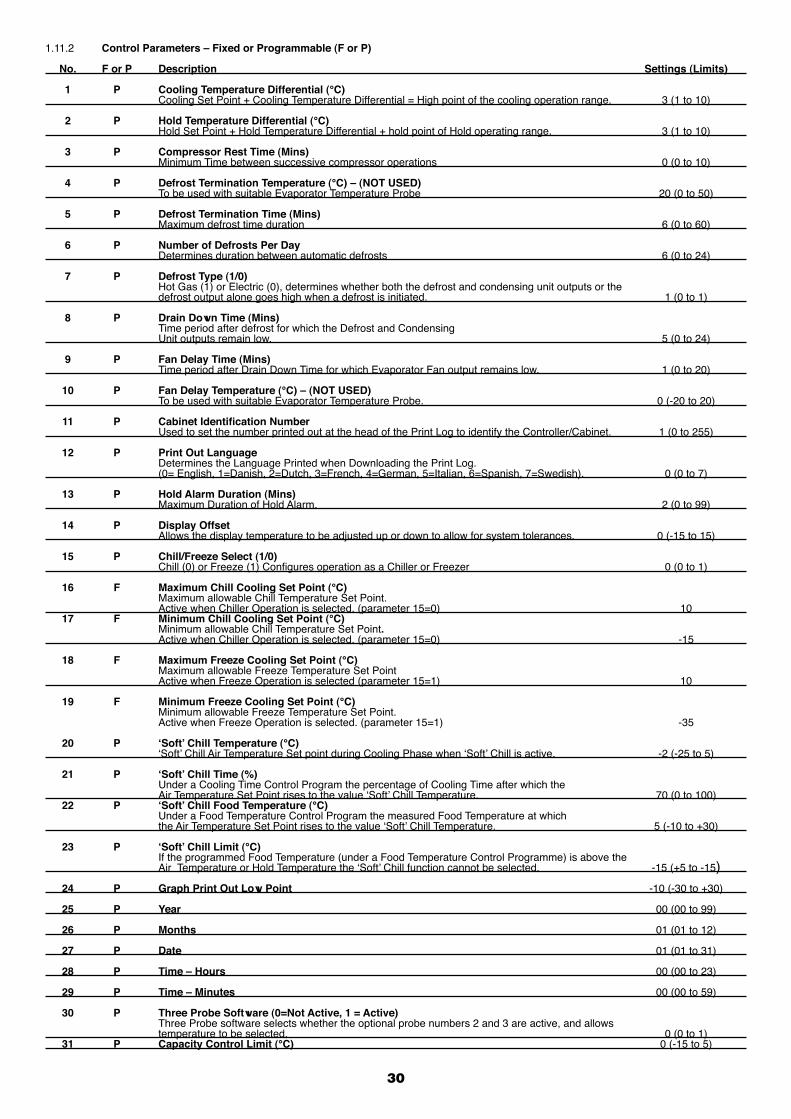
30
1.11.2 Control Parameters – Fixed or Programmable (F or P)
No. F or P Description Settings (Limits)
1 P Cooling Temperature Differential (°C) Cooling Set Point + Cooling Temperature Differential = High point of the cooling operation range. 3 (1 to 10)
2 P Hold Temperature Differential (°C) Hold Set Point + Hold Temperature Differential + hold point of Hold operating range. 3 (1 to 10)
3 P Compressor Rest Time (Mins) Minimum Time between successive compressor operations 0 (0 to 10)
4 P Defrost Termination Temperature (°C) – (NOT USED) To be used with suitable Evaporator Temperature Probe 20 (0 to 50)
5 P Defrost Termination Time (Mins) Maximum defrost time duration 6 (0 to 60)
6 P Number of Defrosts Per Day Determines duration between automatic defrosts 6 (0 to 24)
7 P Defrost Type (1/0) Hot Gas (1) or Electric (0), determines whether both the defrost and condensing unit outputs or the defrost output alone goes high when a defrost is initiated. 1 (0 to 1)
8 P Drain Down Time (Mins) Time period after defrost for which the Defrost and Condensing Unit outputs remain low. 5 (0 to 24)
9 P Fan Delay Time (Mins) Time period after Drain Down Time for which Evaporator Fan output remains low. 1 (0 to 20)
10 P Fan Delay Temperature (°C) – (NOT USED) To be used with suitable Evaporator Temperature Probe. 0 (-20 to 20)
11 P Cabinet Identification Number Used to set the number printed out at the head of the Print Log to identify the Controller/Cabinet. 1 (0 to 255)
12 P Print Out Language Determines the Language Printed when Downloading the Print Log. (0= English, 1=Danish, 2=Dutch, 3=French, 4=German, 5=Italian, 6=Spanish, 7=Swedish). 0 (0 to 7)
13 P Hold Alarm Duration (Mins) Maximum Duration of Hold Alarm. 2 (0 to 99)
14 P Display Offset Allows the display temperature to be adjusted up or down to allow for system tolerances. 0 (-15 to 15)
15 P Chill/Freeze Select (1/0) Chill (0) or Freeze (1) Configures operation as a Chiller or Freezer 0 (0 to 1)
16 F Maximum Chill Cooling Set Point (°C) Maximum allowable Chill Temperature Set Point. Active when Chiller Operation is selected. (parameter 15=0) 10 17 F Minimum Chill Cooling Set Point (°C) Minimum allowable Chill Temperature Set Point. Active when Chiller Operation is selected. (parameter 15=0) -15
18 F Maximum Freeze Cooling Set Point (°C) Maximum allowable Freeze Temperature Set Point Active when Freeze Operation is selected (parameter 15=1) 10
19 F Minimum Freeze Cooling Set Point (°C) Minimum allowable Freeze Temperature Set Point. Active when Freeze Operation is selected. (parameter 15=1) -35
20 P ‘Soft’ Chill Temperature (°C) ‘Soft’ Chill Air Temperature Set point during Cooling Phase when ‘Soft’ Chill is active. -2 (-25 to 5)
21 P ‘Soft’ Chill Time (%) Under a Cooling Time Control Program the percentage of Cooling Time after which the Air Temperature Set Point rises to the value ‘Soft’ Chill Temperature. 70 (0 to 100) 22 P ‘Soft’ Chill Food Temperature (°C) Under a Food Temperature Control Program the measured Food Temperature at which the Air Temperature Set Point rises to the value ‘Soft’ Chill Temperature. 5 (-10 to +30)
23 P ‘Soft’ Chill Limit (°C) If the programmed Food Temperature (under a Food Temperature Control Programme) is above the Air Temperature or Hold Temperature the ‘Soft’ Chill function cannot be selected. -15 (+5 to -15) 24 P Graph Print Out Low Point -10 (-30 to +30)
25 P Year 00 (00 to 99)
26 P Months 01 (01 to 12)
27 P Date 01 (01 to 31)
28 P Time – Hours 00 (00 to 23)
29 P Time – Minutes 00 (00 to 59)
30 P Three Probe Software (0=Not Active, 1 = Active) Three Probe software selects whether the optional probe numbers 2 and 3 are active, and allows temperature to be selected. 0 (0 to 1) 31 P Capacity Control Limit (°C) 0 (-15 to 5)
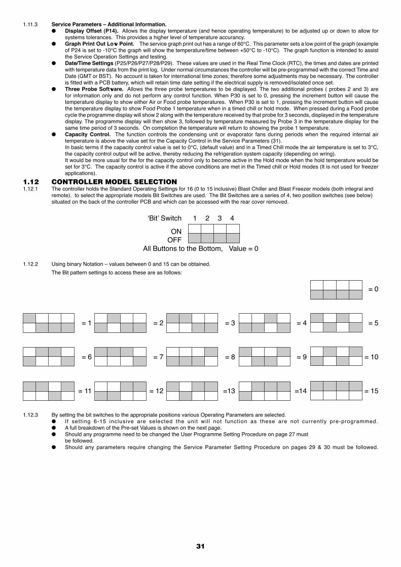
31
1.11.3 Service Parameters – Additional Information.● Display Offset (P14). Allows the display temperature (and hence operating temperature) to be adjusted up or down to allow for
systems tolerances. This provides a higher level of temperature accurancy.● Graph Print Out Low Point. The service graph print out has a range of 60°C. This parameter sets a low point of the graph (example
of P24 is set to -10°C the graph will show the temperature/time between +50°C to -10°C). The graph function is intended to assist the Service Operation Settings and testing.
● Date/Time Settings (P25/P26/P27/P28/P29). These values are used in the Real Time Clock (RTC), the times and dates are printed with temperature data from the print log. Under normal circumstances the controller will be pre-programmed with the correct Time and Date (GMT or BST). No account is taken for international time zones; therefore some adjustments may be necessary. The controller is fitted with a PCB battery, which will retain time date setting if the electrical supply is removed/isolated once set.
● Three Probe Software. Allows the three probe temperatures to be displayed. The two additional probes ( probes 2 and 3) are for information only and do not perform any control function. When P30 is set to 0, pressing the increment button will cause the temperature display to show either Air or Food probe temperatures. When P30 is set to 1, pressing the increment button will cause the temperature display to show Food Probe 1 temperature when in a timed chill or hold mode. When pressed during a Food probe cycle the programme display will show 2 along with the temperature received by that probe for 3 seconds, displayed in the temperature display. The programme display will then show 3, followed by temperature measured by Probe 3 in the temperature display for the same time period of 3 seconds. On completion the temperature will return to showing the probe 1 temperature.
● Capacity Control. The function controls the condensing unit or evaporator fans during periods when the required internal air temperature is above the value set for the Capacity Control in the Service Parameters (31).
In basic terms if the capacity control value is set to 0°C, (default value) and in a Timed Chill mode the air temperature is set to 3°C, the capacity control output will be active, thereby reducing the refrigeration system capacity (depending on wring).
It would be more usual for the for the capacity control only to become active in the Hold mode when the hold temperature would be set for 3°C. The capacity control is active if the above conditions are met in the Timed chill or Hold modes (It is not used for freezer applications).
1.12 CONTROLLER MODEL SELECTION1.12.1 The controller holds the Standard Operating Settings for 16 (0 to 15 inclusive) Blast Chiller and Blast Freezer models (both integral and
remote). to select the appropriate models Bit Switches are used. The Bit Switches are a series of 4, two position switches (see below) situated on the back of the controller PCB and which can be accessed with the rear cover removed.
‘Bit’ Switch 1 2 3 4
ON OFF
All Buttons to the Bottom, Value = 0
1.12.2 Using binary Notation – values between 0 and 15 can be obtained.
The Bit pattern settings to access these are as follows:
= 0
= 1 = 2 = 3 = 4 = 5
= 6 = 7 = 8 = 9 = 10
= 11 = 12 =13 =14 = 15
1.12.3 By setting the bit switches to the appropriate positions various Operating Parameters are selected. ● I f sett ing 6-15 inclusive are selected the unit wil l not function as these are not currently pre-programmed. ● A full breakdown of the Pre-set Values is shown on the next page. ● Should any programme need to be changed the User Programme Setting Procedure on page 27 must be followed. ● Should any parameters require changing the Service Parameter Setting Procedure on pages 29 & 30 must be followed.
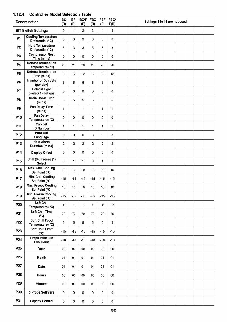
32
1.12.4 Controller Model Selection Table
Denomination
P1
P2
P3
P4
P5
P6
P7
P8
P9
P10
P11
P12
P13
P14
P15
P16
P17
P18
P19
P20
P21
P22
P23
P24
P25
P26
P27
P28
P29
P30
P31
BIT Switch Settings
Cooling Temperature Differential (°C)
Hold TemperatureDifferential (°C)
Compressor RestTime (mins)
Defrost TerminationTemperature (°C)
Defrost TerminationTime (mins)
Number of Defrosts(per day)
Defrost Type(0=elec/ 1=hot gas)Drain Down Time
(mins)Fan Delay Time
(mins)Fan Delay
Temperature (°C)Cabinet
ID NumberPrint OutLanguage
Hold AlarmDuration (mins)
Display Offset
Chill (0) / Freeze (1)Select
Max. Chill CoolingSet Point (°C)
Min. Chill CoolingSet Point (°C)
Max. Freeze CoolingSet Point (°C)
Min. Freeze CoolingSet Point (°C)
Soft ChillTemperature (°C)Soft Chill Time
(%)Soft Chill Food
Temperature (°C)Soft Chill Limit
(°C)Graph Print Out
Low Point
Year
Month
Date
Hours
Minutes
3 Probe Software
Capcity Control
Settings 6 to 15 are not usedFBC/F(R)
FBF(R)
FBC(R)
BC/F(R)
BF(R)
BC(R)
0 1 2 3 4 5
3 3 3 3 3 3
3 3 3 3 3 3
0 0 0 0 0 0
20 20 20 20 20 20
12 12 12 12 12 12
6 6 6 6 6 6
0 0 0 0 0 0
5 5 5 5 5 5
1 1 1 1 1 1
0 0 0 0 0 0
1 1 1 1 1 1
0 0 0 3 3 3
2 2 2 2 2 2
0 0 0 0 0 0
0 1 1 0 1 1
10 10 10 10 10 10
-15 -15 -15 -15 -15 -15
10 10 10 10 10 10
-35 -35 -35 -35 -35 -35
-2 -2 -2 -2 -2 -2
70 70 70 70 70 70
5 5 5 5 5 5
-15 -15 -15 -15 -15 -15
-10 -10 -10 -10 -10 -10
00 00 00 00 00 00
01 01 01 01 01 01
01 01 01 01 01 01
00 00 00 00 00 00
00 00 00 00 00 00
0 0 0 0 0 0
0 0 0 0 0 0

33
1.13 ELECTRICAL CONNECTIONS1.13.1 Ratings Nominal Supply Voltage: 230Va.c. +/-10% Supply Fequency: 50 / 60 Hz Supply Range: 198-254Va.c. Temperature Range: 0 to +70°C Humidity 80%1.13.2 Mains Services Mains Supply: 1 Live (L1), 1 Neutral (N1), 1 Earth (E). Compressor / Solenoid Valve: 1 Switched Live (C). Evaporator Fans: 2 Switched Live (F). Defrost: 2 Switched Live (D). Alarm: 1 Switched Live (A). Common Neutral: 5 Neutral (N).1.13.3 Sensors Printer Connection: Plug In Connection.
Food Probe: 2 Screw Terminals (PRB1). Air Probe: 2 Screw Terminals (PRB2). Resistor 5.1Kohm: 2 Screw Terminals (PRB3). Door Switch: 2 Screw Terminals (DS). Food Probe: 2 Screw Terminals (PRB4). Food Probe: 2 Screw Terminals (PRB5).
1.14 RESISTANCE VALUES: The following table relates to resistance values against temperature.
+60°C 656 ohms +10°C 3448 ohms -20°C 12100 ohms +30°C 1679 ohms 0 5107 ohms -30°C 19455 ohms +20°C 2381 ohms -10°C 7754 ohms -60°C 100181 ohms
OFFON
Bit Switches
N1 E L
(Printer Connections)
BK WH GA R
Remote Keypad
• • • • • • •
h n n u kY OW G B B B
4 3 2 1
N N N N N N N PRB1 A D D F F C P PRB2 PRB3 DS PRB4 PRB5
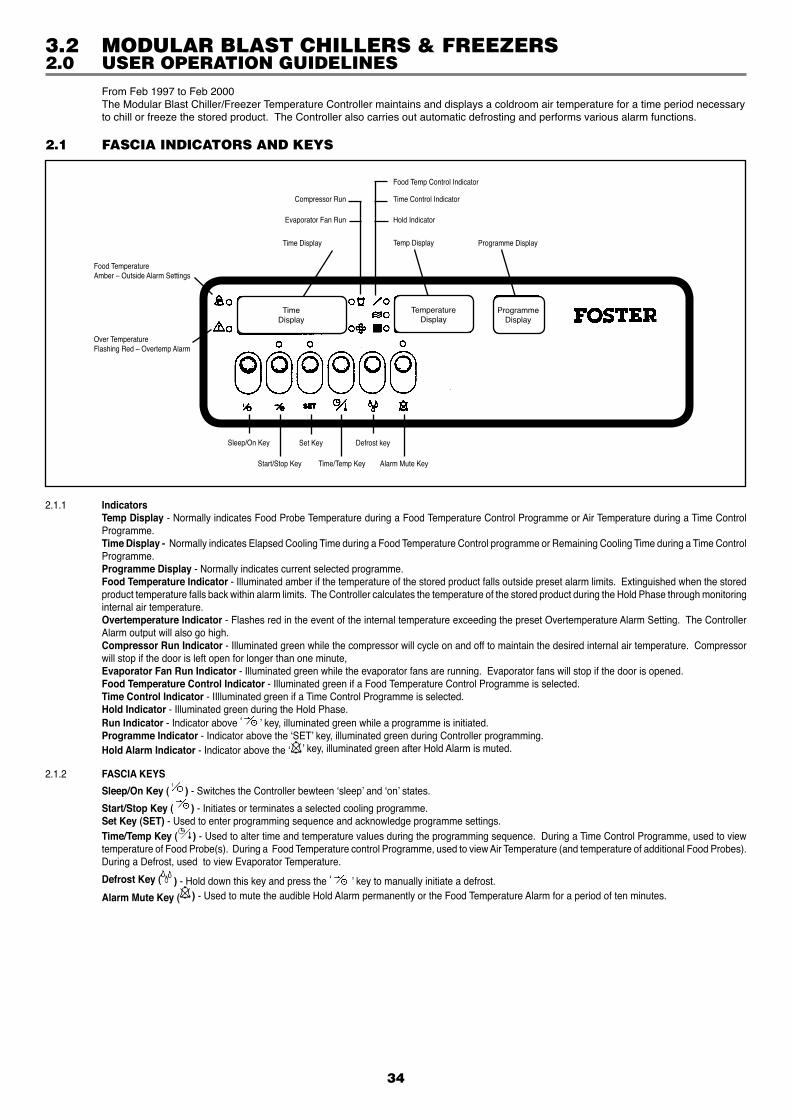
34
From Feb 1997 to Feb 2000 The Modular Blast Chiller/Freezer Temperature Controller maintains and displays a coldroom air temperature for a time period necessary
to chill or freeze the stored product. The Controller also carries out automatic defrosting and performs various alarm functions.
2.1 FASCIA INDICATORS AND KEYS
2.0 USER OPERATION GUIDELINES
2.1.1 Indicators Temp Display - Normally indicates Food Probe Temperature during a Food Temperature Control Programme or Air Temperature during a Time Control
Programme. Time Display - Normally indicates Elapsed Cooling Time during a Food Temperature Control programme or Remaining Cooling Time during a Time Control
Programme. Programme Display - Normally indicates current selected programme. Food Temperature Indicator - Illuminated amber if the temperature of the stored product falls outside preset alarm limits. Extinguished when the stored
product temperature falls back within alarm limits. The Controller calculates the temperature of the stored product during the Hold Phase through monitoring internal air temperature.
Overtemperature Indicator - Flashes red in the event of the internal temperature exceeding the preset Overtemperature Alarm Setting. The Controller Alarm output will also go high.
Compressor Run Indicator - Illuminated green while the compressor will cycle on and off to maintain the desired internal air temperature. Compressor will stop if the door is left open for longer than one minute,
Evaporator Fan Run Indicator - Illuminated green while the evaporator fans are running. Evaporator fans will stop if the door is opened. Food Temperature Control Indicator - Illuminated green if a Food Temperature Control Programme is selected. Time Control Indicator - IIlluminated green if a Time Control Programme is selected. Hold Indicator - Illuminated green during the Hold Phase. Run Indicator - Indicator above ‘ ’ key, illuminated green while a programme is initiated. Programme Indicator - Indicator above the ‘SET’ key, illuminated green during Controller programming. Hold Alarm Indicator - Indicator above the ‘ ’ key, illuminated green after Hold Alarm is muted.
2.1.2 FASCIA KEYS
Sleep/On Key ( ) - Switches the Controller bewteen ‘sleep’ and ‘on’ states.
Start/Stop Key ( ) - Initiates or terminates a selected cooling programme. Set Key (SET) - Used to enter programming sequence and acknowledge programme settings. Time/Temp Key ( ) - Used to alter time and temperature values during the programming sequence. During a Time Control Programme, used to view
temperature of Food Probe(s). During a Food Temperature control Programme, used to view Air Temperature (and temperature of additional Food Probes). During a Defrost, used to view Evaporator Temperature.
Defrost Key ( ) - Hold down this key and press the ‘ ’ key to manually initiate a defrost.
Alarm Mute Key ( ) - Used to mute the audible Hold Alarm permanently or the Food Temperature Alarm for a period of ten minutes.
Food Temp Control Indicator
Time Control Indicator
Hold Indicator
Temp Display Programme DisplayTime Display
Compressor Run
Evaporator Fan Run
Food TemperatureAmber – Outside Alarm Settings
Over TemperatureFlashing Red – Overtemp Alarm
Sleep/On Key Set Key Defrost key
Start/Stop Key Time/Temp Key Alarm Mute Key
3.2 MODULAR BLAST CHILLERS & FREEZERS
TimeDisplay
TemperatureDisplay
ProgrammeDisplay
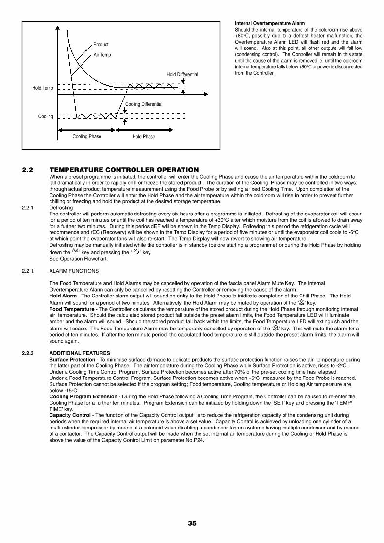
Internal Overtemperature AlarmShould the internal temperature of the coldroom rise above +80oC, possibly due to a defrost heater malfunction, the Overtemperature Alarm LED will flash red and the alarm will sound. Also at this point, all other outputs will fall low (condensing control). The Controller will remain in this state until the cause of the alarm is removed ie. until the coldroom internal temperature falls below +80oC or power is disconnected from the Controller.
2.2 TEMPERATURE CONTROLLER OPERATION When a preset programme is initiated, the controller will enter the Cooling Phase and cause the air temperature within the coldroom to
fall dramatically in order to rapidly chill or freeze the stored product. The duration of the Cooling Phase may be controlled in two ways; through actual product temperature measurement using the Food Probe or by setting a fixed Cooling Time. Upon completion of the Cooling Phase the Controller will enter the Hold Phase and the air temperature within the coldroom will rise in order to prevent further chilling or freezing and hold the product at the desired storage temperature.
2.2.1 Defrosting The controller will perform automatic defrosting every six hours after a programme is initiated. Defrosting of the evaporator coil will occur
for a period of ten minutes or until the coil has reached a temperature of +30oC after which moisture from the coil is allowed to drain away for a further two minutes. During this perios dEF will be shown in the Temp Display. Following this period the refrigeration cycle will recommence and rEC (Recovery) will be shown in the Temp Display for a period of five minutes or until the evaporator coil cools to -5oC at which point the evaporator fans will also re-start. The Temp Display will now revert to showing air temperature.
Defrosting may be manually initiated while the controller is in standby (before starting a programme) or during the Hold Phase by holding down the ‘ ’ key and pressing the ‘ ’ key.
See Operation Flowchart.
2.2.1. ALARM FUNCTIONS
The Food Temperature and Hold Alarms may be cancelled by operation of the fascia panel Alarm Mute Key. The internal Overtemperature Alarm can only be cancelled by resetting the Controller or removing the cause of the alarm.
Hold Alarm - The Controller alarm output will sound on entry to the Hold Phase to inidicate completion of the Chill Phase. The Hold Alarm will sound for a period of two minutes. Alternatively, the Hold Alarm may be muted by operation of the ‘ ’ key.
Food Temperature - The Controller calculates the temperature of the stored product during the Hold Phase through monitoring internal air temperature. Should the calculated stored product fall outside the preset alarm limits, the Food Temperature LED will illuminate amber and the alarm will sound. Should the stored product fall back within the limits, the Food Temperature LED will extinguish and the alarm will cease. The Food Temperature Alarm may be temporarily cancelled by operation of the ‘ ’ key. This will mute the alarm for a period of ten minutes. If after the ten minute period, the calculated food temperature is still outside the preset alarm limits, the alarm will sound again.
2.2.3 ADDITIONAL FEATURES Surface Protection - To minimise surface damage to delicate products the surface protection function raises the air temperature during
the latter part of the Cooling Phase. The air temperature during the Cooling Phase while Surface Protection is active, rises to -2oC. Under a Cooling Time Control Program, Surface Protection becomes active after 70% of the pre-set cooling time has elapsed. Under a Food Temperature Control Program, Surface Protection becomes active when +5oC ,measured by the Food Probe is reached. Surface Protection cannot be selected if the program setting; Food temperature, Cooling temperature or Holding Air temperature are
below -15oC. Cooling Program Extension - During the Hold Phase following a Cooling Time Program, the Controller can be caused to re-enter the
Cooling Phase for a further ten minutes. Program Extension can be initiated by holding down the ‘SET’ key and pressing the ‘TEMP/TIME’ key.
Capacity Control - The function of the Capacity Control output is to reduce the refrigeration capacity of the condensing unit during periods when the required internal air temperature is above a set value. Capacity Control is achieved by unloading one cylinder of a multi-cylinder compressor by means of a solenoid valve disabling a condenser fan on systems having multiple condenser and by means of a contactor. The Capacity Control output will be made when the set internal air temperature during the Cooling or Hold Phase is above the value of the Capacity Control Limit on parameter No.P24.
35
Hold Temp
Cooling
Cooling Phase Hold Phase
Cooling Differential
Hold Differential
Product
Air Temp
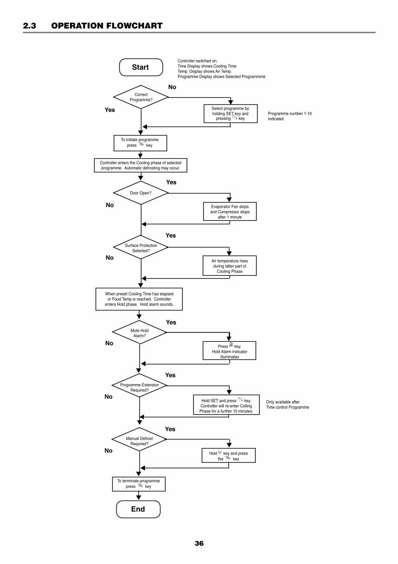
2.3 OPERATION FLOWCHART
36
Start
End
Yes
No
Yes
No
Yes
No
No
Yes
Yes
Yes
No
No
Only available afterTime control Programme
Programme number 1-10indicated
Controller switched on.Time Display shows Cooling TimeTemp. Display shows Air Temp.Programme Display shows Selected Programmme
CorrectProgramme?
Select programme byholding SET key and
pressing key
To initiate programmepress key
Controller enters the Cooling phase of selected programme. Automatic defrosting may occur.
Door Open?
Evaporator Fan stops and Compressor stops
after 1 minute
Air temperature risesduring latter part of
Cooling Phase
Surface ProtectionSelected?
When preset Cooling Time has elapsedor Food Temp is reached. Controller
enters Hold phase. Hold alarm sounds.
Mute HoldAlarm?
Programme ExtensionRequired?
Press key.Hold Alarm Indicator
illuminates
Hold SET and press key.Controller will re-enter Colling
Phase for a further 10 minutes.
Manual DefrostRequired?
Hold key and pressthe key
To terminate programmepress key
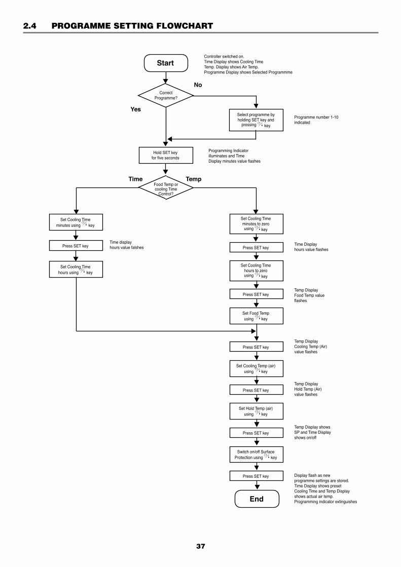
2.4 PROGRAMME SETTING FLOWCHART
37
Start
Yes
No
Programme number 1-10indicated
Controller switched on.Time Display shows Cooling TimeTemp. Display shows Air Temp.Programme Display shows Selected Programmme
CorrectProgramme?
Select programme byholding SET key and
pressing key
Hold SET keyfor five seconds
Food Temp orcooling Time
Control?
Time Temp
Programming Indicatorilluminates and TimeDisplay minutes value flashes
Set Cooling Timeminutes using key
Press SET key
Set Cooling Timehours using key
Time displayhours value falshes
Set Cooling Timeminutes to zerousing key
Press SET key
Set Cooling Timehours to zerousing key
Press SET key
Press SET key
Set Food Tempusing key
Set Cooling Temp (air)using key
Press SET key
Set Hold Temp (air)using key
Press SET key
Switch on/off SurfaceProtection using key
Press SET key
End
Time Displayhours value flashes
Temp DisplayFood Temp valueflashes
Temp DisplayCooling Temp (Air)value flashes
Temp DisplayHold Temp (Air)value flashes
Temp Display showsSP and Time Displayshows on/off
Display flash as newprogramme settings are stored.Time Display shows presetCooling Time and Temp Displayshows actual air temp.Programming indicator extinguishes
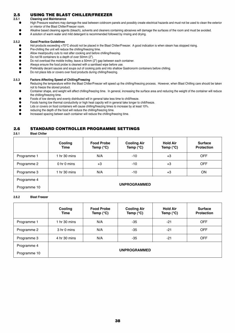
38
2.5 USING THE BLAST CHILLER/FREEZER2.5.1 Cleaning and Maintenance ● High Pressure washers may damage the seal between coldroom panels and possibly create electrical hazards and must not be used to clean the exterior
or interior of the Blast Chiller/Freezer room. ● Alkaline based cleaning agents (bleach), solvents and cleaners containing abrasives will damage the surfaces of the room and must be avoided. ● A solution of warm water and mild detergent is recommended followed by rinsing and drying.
2.5.2 Good Practice Guidelines ● Hot products exceeding +70°C should not be placed in the Blast Chiller/Freezer. A good indication is when steam has stopped rising. ● Pre-chilling the unit will reduce the chilling/freezing time. ● Allow meat/poultry cuts to rest after cooking and before chilling/freezing. ● Do not fill containers to a depth of over 50mm (2”). ● Do not overload the mobile trolley, leave a 50mm (2”) gap between each container. ● Always ensure the food probe is cleaned with a sanitised wipe before use. ● Preferably decant sauces and soups out of cooking pots and into shallow Gastronorm containers before chilling. ● Do not place lids or covers over food products during chilling/freezing.
2.5.3 Factors Affecting Speed of Chilling/Freezing ● Reducing the temperature within the Blast Chiller/Freezer will speed up the chilling/freezing process. However, when Blast Chilling care should be taken
not to freeze the stored product. ● Container shape, and weight will affect chilling/freezing time. In general, increasing the surface area and reducing the weight of the container will reduce
the chilling/freezing time. ● Foods of low density and evenly distributed will in general take less time to chill/freeze. ● Foods having low thermal conductivity or high heat capcity will in general take longer to chill/freeze. ● Lids or covers on food containers will cause chilling/freezing times to increase by at least 10%. ● reducing the depth of the food will reduce the chilling/freezing time. ● Increased spacing betwen each container will reduce the chilling/freezing time.
2.6 STANDARD CONTROLLER PROGRAMME SETTINGS2.6.1 Blast Chiller
Cooling Time
Food ProbeTemp (°C)
Cooling AirTemp (°C)
Hold AirTemp (°C)
SurfaceProtection
Programme 1 1 hr 30 mins N/A -10 +3 OFF
Programme 2 0 hr 0 mins +3 -10 +3 OFF
Programme 3 1 hr 30 mins N/A -10 +3 ON
Programme 4
Programme 10UNPROGRAMMED
2.6.2 Blast Freezer
Cooling Time
Food ProbeTemp (°C)
Cooling AirTemp (°C)
Hold AirTemp (°C)
SurfaceProtection
Programme 1 1 hr 30 mins N/A -35 -21 OFF
Programme 2 3 hr 0 mins N/A -35 -21 OFF
Programme 3 4 hr 30 mins N/A -35 -21 OFF
Programme 4
Programme 10UNPROGRAMMED
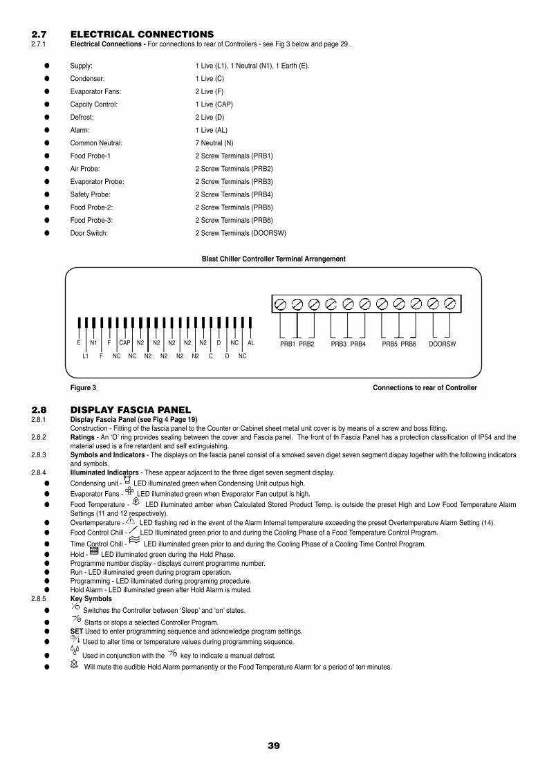
2.7 ELECTRICAL CONNECTIONS2.7.1 Electrical Connections - For connections to rear of Controllers - see Fig 3 below and page 29.
● Supply: 1 Live (L1), 1 Neutral (N1), 1 Earth (E).
● Condenser: 1 Live (C)
● Evaporator Fans: 2 Live (F)
● Capcity Control: 1 Live (CAP)
● Defrost: 2 Live (D)
● Alarm: 1 Live (AL)
● Common Neutral: 7 Neutral (N)
● Food Probe-1 2 Screw Terminals (PRB1)
● Air Probe: 2 Screw Terminals (PRB2)
● Evaporator Probe: 2 Screw Terminals (PRB3)
● Safety Probe: 2 Screw Terminals (PRB4)
● Food Probe-2: 2 Screw Terminals (PRB5)
● Food Probe-3: 2 Screw Terminals (PRB6)
● Door Switch: 2 Screw Terminals (DOORSW)
Blast Chiller Controller Terminal Arrangement
Figure 3 Connections to rear of Controller
39
PRB1 PRB2 PRB3 PRB4 PRB5 PRB6 DOORSWE N1 F CAP N2 N2 N2 N2 N2 D NC AL
L1 F NC NC N2 N2 N2 N2 C D NC
2.8 DISPLAY FASCIA PANEL2.8.1 Display Fascia Panel (see Fig 4 Page 19) Construction - Fitting of the fascia panel to the Counter or Cabinet sheet metal unit cover is by means of a screw and boss fitting.2.8.2 Ratings - An ‘O’ ring provides sealing between the cover and Fascia panel. The front of th Fascia Panel has a protection classification of IP54 and the
material used is a fire retardent and self extinguishing.2.8.3 Symbols and Indicators - The displays on the fascia panel consist of a smoked seven diget seven segment dispay together with the following indicators
and symbols.2.8.4 Illuminated Indicators - These appear adjacent to the three diget seven segment display. ● Condensing unit - LED illuminated green when Condensing Unit outpus high. ● Evaporator Fans - LED illuminated green when Evaporator Fan output is high. ● Food Temperature - LED illuminated amber when Calculated Stored Product Temp. is outside the preset High and Low Food Temperature Alarm
Settings (11 and 12 respectively). ● Overtemperature - LED flashing red in the event of the Alarm Internal temperature exceeding the preset Overtemperature Alarm Setting (14). ● Food Control Chill - LED Illuminated green prior to and during the Cooling Phase of a Food Temperature Control Program.
● Time Control Chill - LED illuminated green prior to and during the Cooling Phase of a Cooling Time Control Program. ● Hold - LED illuminated green during the Hold Phase. ● Programme number display - displays current programme number. ● Run - LED illuminated green during program operation. ● Programming - LED illuminated during programing procedure. ● Hold Alarm - LED illuminated green after Hold Alarm is muted.2.8.5 Key Symbols
● Switches the Controller between ‘Sleep’ and ‘on’ states.
● Starts or stops a selected Controller Program. ● SET Used to enter programming sequence and acknowledge program settings. ● Used to alter time or temperature values during programming sequence.
● Used in conjunction with the key to indicate a manual defrost.
● Will mute the audible Hold Alarm permanently or the Food Temperature Alarm for a period of ten minutes.

2.9 OPERATION In this section the behaviour of the Controller is described in the form of a list of events (Event/response list) with regard to the cold room refrigeration
components.2.9.1 Refrigeration and Defrost.2.9.2 Power Connected to Cold Room - The Controller is in a ‘sleep’ mode, three bars are displayed on the fascia panel, all outputs are in a low state.2.9.3 ‘I/O’ Key Depressed - The Controller switches on, fascia panel indicates program time and internal air temperature. Any one of ten stored programs may
be selected. Program settings may also be altered.2.9.4 Start/Stop Key Depressed - The selected Controller is indicated.2.9.5 Chill Phase - If the selected program is a Food Temperature Control Program, the following sequence of events will occur - (See list of Control parameters,
Page 9 and 10). The fascia panel dispays Chill Time (set to zero) & Food Temp. (measured by Food Probe 1). The Evaporator fan output goes high and the refrigeration
cycle begins. The Chill Time displayed on the fascia panel will increment from zero. If internal Air Temp is higher than the preset Air Temperature plus Chill Temperature Differential (1) the Condensing Unit output goes high.
When the internal air temperature pulls down to the preset Air Temperature, the Condensing Unit output goes low. This Chill Phase continues until the preset Food Temperature is reached. The displayed Chill Time stops incrementing & holds the displayed value (Duration of Chill Phase).
Or if the selected program is a Chill Time Control program, the following sequence of events occurs.
The fascia panel displays Chill Time and Air Temperature. The evaporator fan output goes high and the refrigeration cycle begins. The Chill Time displayed on the fascia panel will decrement from the programmed value. If the internal air temperature is higher than the preset Air Temp plus Chill Temperature Differential (1) the Condensing Unit output goes high. When the internal air temperature pulls down to the preset Air Temperature, the Condensing Unit output goes low. This Chill Phase continues until the displayed time decrements to zero.
2.9.6 Hold Phase - The Hold Alarm output goes high to indicate completion of the Chill Phase. With the evaporator fan output still high, the condensing unit output falls low until the internal air temperature rises to the preset Hold Temperature plus Hold Temperature Differential (2).
The condensing unit output goes high until the internal air temperature pulls down to the preset Hold Temperature. The Hold Phase continues until the program is stopped by operation of the start/stop key.
2.10 SURROUNDINGS AND EXTERNAL INFLUENCES2.10.1 Inputs ● Food Temp Probe-1 Senses stored product temperature. Used for control. Negative temperature/resistance coefficient thermistor probe. ● Air Temp Probe Senses internal air temperature. Negative temperature/resistance coefficient thermistor probe. ● Evap Temp Probe Senses temperature at the evaporator coil, required to terminate defrost. Negative temperature/resistance coefficient thermistor probe. ● Safety Probe Senses temperature at the evaporator coil in order to detect an internal overtemperature. High temperature, Negative temperature/resistance coefficient thermistor probe. ● Food Temp Probe-2 Senses stored product temperature. Optional, used for indication only. Negative temperature/resistance coefficient thermistor probe. ● Food Temp Probe-3 Senses stored product temperature. Optional, used for indication only. Negative temperature/resistance coefficient thermistor probe. ● Door Switch Voltage free contacts, open circuit when door is open causing evaporator fan output to fall low and condensing unit output to fall low after a period of one
minute. ● Display Fascia Used to switch On/Off the Controller. Initiate or terminate a Chill or Freeze program. Program in operating parameters. Manually initiate a defrost. Cancel all alarm outputs.2.10.2 Outputs ● Condensing Unit Relay output switching single phase mains supply to condensing unit (compressor and condenser fan). Contact 250 Va.c. 10 A. ● Evaporator Fan Relay output switching single phase mains supply to evaporator fans. Also, in parallel with the evaporator fans are connected the mullion and vaporiser
tray heaters. Contact rating 250 Va.c. 10 A. ● Capacity Control Relay output switching single phase mains supply to condenser fan contactor or condensing unit unloading solenoid. Contact rating 250 Va.c. 10 A. ● Defrost Relay output switching single phase mains supply to hot gas solenoid or, electric heaters. Contact rating 250 Va.c. 10 A. ● External Alarm Relay output switching single phase mains supply to alarm, activated when chill phase is completed, when calculated food temperature is outside preset
limits (during Hold Phase) and in the event of an internal overtemperature. Contact rating 250 Va.c. 10 A. ● Display Fascia Seven segment display, nine digits. Normally indicating cabinet air or product temperature & cooling time. To display parameter values during controller programming . Status indicatin during defrost. Indicator LEDs representing current control phase, selected program and status of rerigeration component outputs.
40
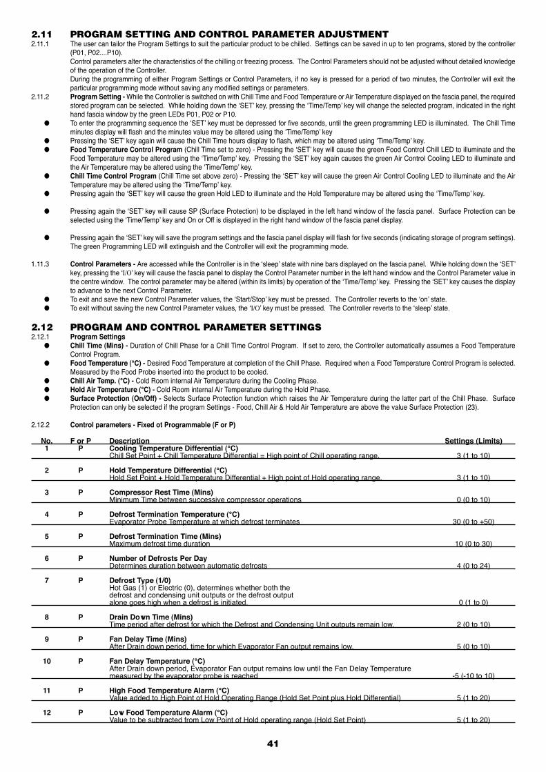
2.11 PROGRAM SETTING AND CONTROL PARAMETER ADJUSTMENT2.11.1 The user can tailor the Program Settings to suit the particular product to be chilled. Settings can be saved in up to ten programs, stored by the controller
(P01, P02....P10). Control parameters alter the characteristics of the chilling or freezing process. The Control Parameters should not be adjusted without detailed knowledge
of the operation of the Controller. During the programming of either Program Settings or Control Parameters, if no key is pressed for a period of two minutes, the Controller will exit the
particular programming mode without saving any modified settings or parameters.2.11.2 Program Setting - While the Controller is switched on with Chill Time and Food Temperature or Air Temperature displayed on the fascia panel, the required
stored program can be selected. While holding down the ‘SET’ key, pressing the ‘Time/Temp’ key will change the selected program, indicated in the right hand fascia window by the green LEDs P01, P02 or P10.
● To enter the programming sequence the ‘SET’ key must be depressed for five seconds, until the green programming LED is illuminated. The Chill Time minutes display will flash and the minutes value may be altered using the ‘Time/Temp’ key
● Pressing the ‘SET’ key again will cause the Chill Time hours display to flash, which may be altered using ‘Time/Temp’ key. ● Food Temperature Control Program (Chill Time set to zero) - Pressing the ‘SET’ key will cause the green Food Control Chill LED to illuminate and the
Food Temperature may be altered using the ‘Time/Temp’ key. Pressing the ‘SET’ key again causes the green Air Control Cooling LED to illuminate and the Air Temperature may be altered using the ‘Time/Temp’ key.
● Chill Time Control Program (Chill Time set above zero) - Pressing the ‘SET’ key will cause the green Air Control Cooling LED to illuminate and the Air Temperature may be altered using the ‘Time/Temp’ key.
● Pressing again the ‘SET’ key will cause the green Hold LED to illuminate and the Hold Temperature may be altered using the ‘Time/Temp’ key.
● Pressing again the ‘SET’ key will cause SP (Surface Protection) to be displayed in the left hand window of the fascia panel. Surface Protection can be selected using the ‘Time/Temp’ key and On or Off is displayed in the right hand window of the fascia panel display.
● Pressing again the ‘SET’ key will save the program settings and the fascia panel display will flash for five seconds (indicating storage of program settings). The green Programming LED will extinguish and the Controller will exit the programming mode.
1.11.3 Control Parameters - Are accessed while the Controller is in the ‘sleep’ state with nine bars displayed on the fascia panel. While holding down the ‘SET’ key, pressing the ‘I/O’ key will cause the fascia panel to display the Control Parameter number in the left hand window and the Control Parameter value in the centre window. The control parameter may be altered (within its limits) by operation of the ‘Time/Temp’ key. Pressing the ‘SET’ key causes the display to advance to the next Control Parameter.
● To exit and save the new Control Parameter values, the ‘Start/Stop’ key must be pressed. The Controller reverts to the ‘on’ state. ● To exit without saving the new Control Parameter values, the ‘I/O’ key must be pressed. The Controller reverts to the ‘sleep’ state.
2.12 PROGRAM AND CONTROL PARAMETER SETTINGS2.12.1 Program Settings ● Chill Time (Mins) - Duration of Chill Phase for a Chill Time Control Program. If set to zero, the Controller automatically assumes a Food Temperature
Control Program. ● Food Temperature (°C) - Desired Food Temperature at completion of the Chill Phase. Required when a Food Temperature Control Program is selected.
Measured by the Food Probe inserted into the product to be cooled. ● Chill Air Temp. (°C) - Cold Room internal Air Temperature during the Cooling Phase. ● Hold Air Temperature (°C) - Cold Room internal Air Temperature during the Hold Phase. ● Surface Protection (On/Off) - Selects Surface Protection function which raises the Air Temperature during the latter part of the Chill Phase. Surface
Protection can only be selected if the program Settings - Food, Chill Air & Hold Air Temperature are above the value Surface Protection (23).
2.12.2 Control parameters - Fixed ot Programmable (F or P)
No. F or P Description Settings (Limits) 1 P Cooling Temperature Differential (°C) Chill Set Point + Chill Temperature Differential = High point of Chill operating range. 3 (1 to 10)
2 P Hold Temperature Differential (°C) Hold Set Point + Hold Temperature Differential + High point of Hold operating range. 3 (1 to 10)
3 P Compressor Rest Time (Mins) Minimum Time between successive compressor operations 0 (0 to 10)
4 P Defrost Termination Temperature (°C) Evaporator Probe Temperature at which defrost terminates 30 (0 to +50)
5 P Defrost Termination Time (Mins) Maximum defrost time duration 10 (0 to 30)
6 P Number of Defrosts Per Day Determines duration between automatic defrosts 4 (0 to 24)
7 P Defrost Type (1/0) Hot Gas (1) or Electric (0), determines whether both the defrost and condensing unit outputs or the defrost output alone goes high when a defrost is initiated. 0 (1 to 0)
8 P Drain Down Time (Mins) Time period after defrost for which the Defrost and Condensing Unit outputs remain low. 2 (0 to 10)
9 P Fan Delay Time (Mins) After Drain down period, time for which Evaporator Fan output remains low. 5 (0 to 10)
10 P Fan Delay Temperature (°C) After Drain down period, Evaporator Fan output remains low until the Fan Delay Temperature measured by the evaporator probe is reached -5 (-10 to 10)
11 P High Food Temperature Alarm (°C) Value added to High Point of Hold Operating Range (Hold Set Point plus Hold Differential) 5 (1 to 20)
12 P Low Food Temperature Alarm (°C) Value to be subtracted from Low Point of Hold operating range (Hold Set Point) 5 (1 to 20)
41
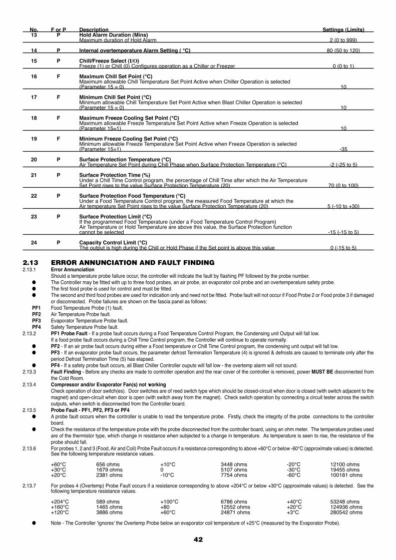
No. F or P Description Settings (Limits) 13 P Hold Alarm Duration (Mins) Maximum duration of Hold Alarm 2 (0 to 999)
14 P Internal overtemperature Alarm Setting ( °C) 80 (50 to 120)
15 P Chill/Freeze Select (I/O) Freeze (1) or Chill (0) Configures operation as a Chiller or Freezer 0 (0 to 1)
16 F Maximum Chill Set Point (°C) Maximum allowable Chill Temperature Set Point Active when Chiller Operation is selected (Parameter 15 = 0) 10
17 F Minimum Chill Set Point (°C) Minimum allowable Chill Temperature Set Point Active when Blast Chiller Operation is selected (Parameter 15 = 0) 10
18 F Maximum Freeze Cooling Set Point (°C) Maximum allowable Freeze Temperature Set Point Active when Freeze Operation is selected (Parameter 15=1) 10
19 F Minimum Freeze Cooling Set Point (°C) Minimum allowable Freeze Temperature Set Point Active when Freeze Operation is selected (Parameter 15=1) -35
20 P Surface Protection Temperature (°C) Air Temperature Set Point during Chill Phase when Surface Protection Temperature (°C) -2 (-25 to 5)
21 P Surface Protection Time (%) Under a Chill Time Control program, the percentage of Chill Time after which the Air Temperature Set Point rises to the value Surface Protection Temperature (20) 70 (0 to 100)
22 P Surface Protection Food Temperature (°C) Under a Food Temperature Control program, the measured Food Temperature at which the Air temperature Set Point rises to the value Surface Protection Temperature (20) 5 (-10 to +30)
23 P Surface Protection Limit (°C) If the programmed Food Temperature (under a Food Temperature Control Program) Air Temperature or Hold Temperature are above this value, the Surface Protection function cannot be selected -15 (-15 to 5)
24 P Capacity Control Limit (°C) The output is high during the Chill or Hold Phase if the Set point is above this value 0 (-15 to 5)
42
2.13 ERROR ANNUNCIATION AND FAULT FINDING2.13.1 Error Annunciation Should a temperature probe failure occur, the controller will indicate the fault by flashing PF followed by the probe number. ● The Controller may be fitted with up to three food probes, an air probe, an evaporator coil probe and an overtemperature safety probe. ● The first food probe is used for control and must be fitted. ● The second and third food probes are used for indication only and need not be fitted. Probe fault will not occur if Food Probe 2 or Food probe 3 if damaged
or disconnected. Probe failures are shown on the fascia panel as follows: PF1 Food Temperature Probe (1) fault. PF2 Air Temperature Probe fault. PF3 Evaporator Temperature Probe fault. PF4 Safety Temperature Probe fault.2.13.2 PF1 Probe Fault - If a probe fault occurs during a Food Temperature Control Program, the Condensing unit Output will fall low. If a food probe fault occurs during a Chill Time Control program, the Controller will continue to operate normally. ● PF2 - If an air probe fault occurs during either a Food temperature or Chill Time Control program, the condensing unit output will fall low. ● PF3 - If an evaporator probe fault occurs, the parameter defrost Termination Temperature (4) is ignored & defrosts are caused to terminate only after the
period Defrost Termination Time (5) has elapsed. ● PF4 - If a safety probe fault occurs, all Blast Chiller Controller ouputs will fall low - the overtemp alarm will not sound.2.13.3 Fault Finding - Before any checks are made to controller operation and the rear cover of the controller is removed, power MUST BE disconnected from
the Cold Room.2.13.4 Compressor and/or Evaporator Fan(s) not working Check operation of door switch(es). Door switches are of reed switch type which should be closed-circuit when door is closed (with switch adjacent to the
magnet) and open-circuit when door is open (with switch away from the magnet). Check switch operation by connecting a circuit tester across the switch outputs, when switch is disconnected from the Controller board.
2.13.5 Probe Fault - PF1, PF2, PF3 or PF4 ● A probe fault occurs when the controller is unable to read the temperature probe. Firstly, check the integrity of the probe connections to the controller
board. ● Check the resistance of the temperature probe with the probe disconnected from the controller board, using an ohm meter. The temperature probes used
are of the thermistor type, which change in resistance when subjected to a change in temperature. As temperature is seen to rise, the resistance of the probe should fall.
2.13.6 For probes 1, 2 and 3 (Food, Air and Coil) Probe Fault occurs if a resistance corresponding to above +60°C or below -60°C (approximate values) is detected. See the following temperature resistance values.
+60°C 656 ohms +10°C 3448 ohms -20°C 12100 ohms +30°C 1679 ohms 0 5107 ohms -30°C 19455 ohms +20°C 2381 ohms -10°C 7754 ohms -60°C 100181 ohms
2.13.7 For probes 4 (Overtemp) Probe Fault occurs if a resistance corresponding to above +204°C or below +30°C (approximate values) is detected. See the following temperature resistance values.
+204°C 589 ohms +100°C 6786 ohms +40°C 53248 ohms +160°C 1465 ohms +80 12552 ohms +20°C 124936 ohms +120°C 3886 ohms +60°C 24871 ohms +3°C 280542 ohms
● Note - The Controller ‘ignores’ the Overtemp Probe below an evaporator coil temperature of +25°C (measured by the Evaporator Probe).
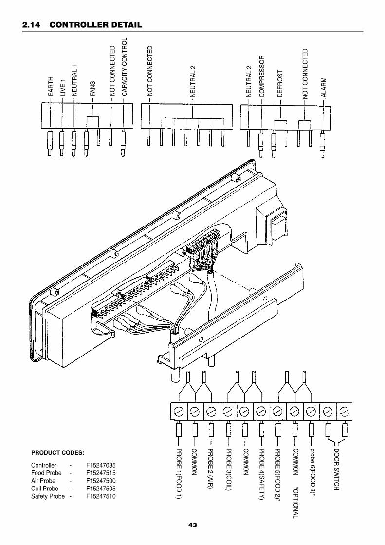
2.14 CONTROLLER DETAIL
43
PRODUCT CODES:
Controller - F15247085 Food Probe - F15247515 Air Probe - F15247500 Coil Probe - F15247505 Safety Probe - F15247510
DO
OR
SWITC
H
probe 6(FOO
D 3)*
CO
MM
ON
*OPTIO
NAL
PRO
BE 5(FOO
D 2)*
PRO
BE 4(SAFETY)
CO
MM
ON
PRO
BE 3(CO
IL)
PRO
BE 2 (AIR)
CO
MM
ON
PRO
BE 1(FOO
D 1)
EAR
TH
LIVE
1
NEU
TRAL
1
FAN
S
NO
T C
ON
NEC
TED
CAP
ACIT
Y C
ON
TRO
L
NO
T C
ON
NEC
TED
NEU
TRAL
2
NEU
TRAL
2
CO
MPR
ESSO
R
DEF
RO
ST
NO
T C
ON
NEC
TED
ALAR
M
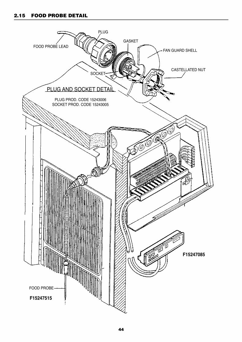
2.15 FOOD PROBE DETAIL
44
FOOD PROBE
F15247515
F15247085
FOOD PROBE LEAD
PLUG
GASKET
SOCKET
FAN GUARD SHELL
CASTELLATED NUT
PLUG AND SOCKET DETAIL
PLUG PROD. CODE 15243006SOCKET PROD. CODE 15243005
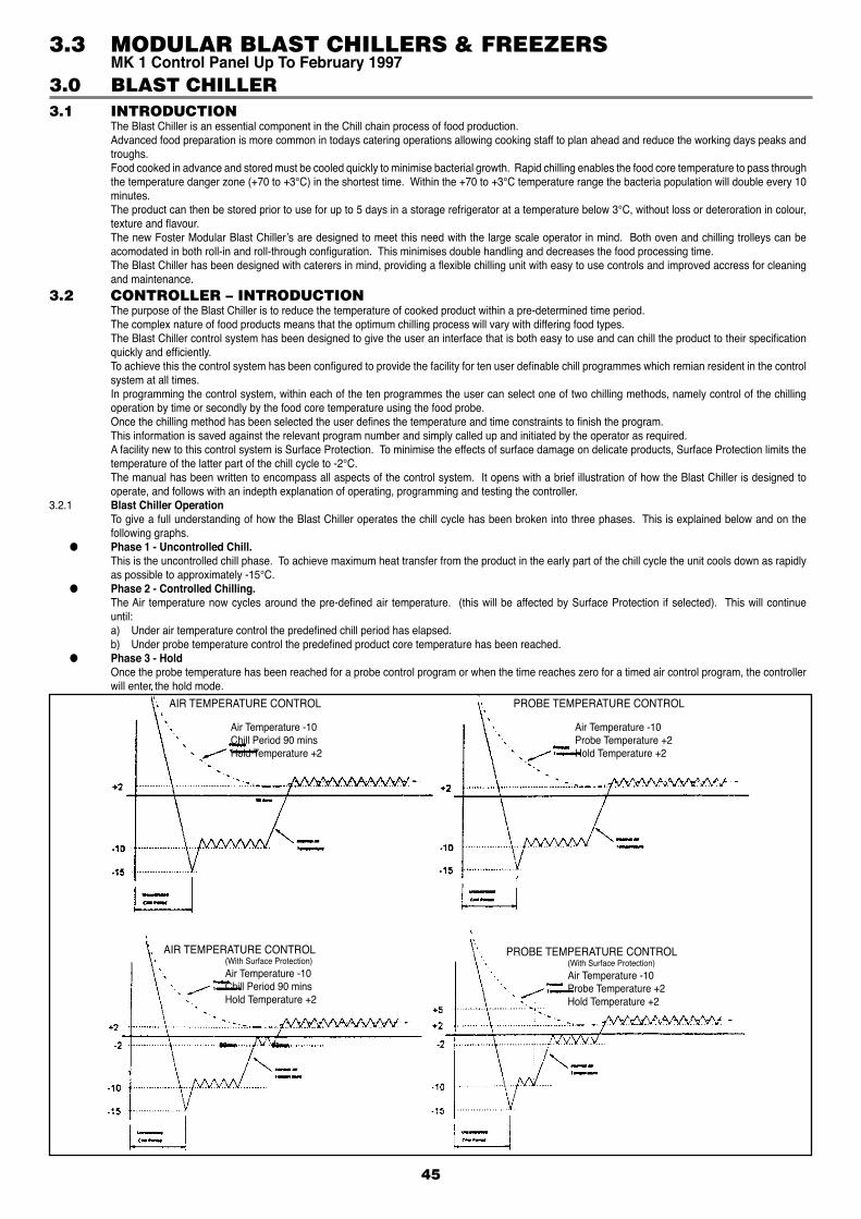
3.1 INTRODUCTION The Blast Chiller is an essential component in the Chill chain process of food production. Advanced food preparation is more common in todays catering operations allowing cooking staff to plan ahead and reduce the working days peaks and
troughs. Food cooked in advance and stored must be cooled quickly to minimise bacterial growth. Rapid chilling enables the food core temperature to pass through
the temperature danger zone (+70 to +3°C) in the shortest time. Within the +70 to +3°C temperature range the bacteria population will double every 10 minutes.
The product can then be stored prior to use for up to 5 days in a storage refrigerator at a temperature below 3°C, without loss or deteroration in colour, texture and flavour.
The new Foster Modular Blast Chiller’s are designed to meet this need with the large scale operator in mind. Both oven and chilling trolleys can be acomodated in both roll-in and roll-through configuration. This minimises double handling and decreases the food processing time.
The Blast Chiller has been designed with caterers in mind, providing a flexible chilling unit with easy to use controls and improved accress for cleaning and maintenance.
3.2 CONTROLLER – INTRODUCTION The purpose of the Blast Chiller is to reduce the temperature of cooked product within a pre-determined time period. The complex nature of food products means that the optimum chilling process will vary with differing food types. The Blast Chiller control system has been designed to give the user an interface that is both easy to use and can chill the product to their specification
quickly and efficiently. To achieve this the control system has been configured to provide the facility for ten user definable chill programmes which remian resident in the control
system at all times. In programming the control system, within each of the ten programmes the user can select one of two chilling methods, namely control of the chilling
operation by time or secondly by the food core temperature using the food probe. Once the chilling method has been selected the user defines the temperature and time constraints to finish the program. This information is saved against the relevant program number and simply called up and initiated by the operator as required. A facility new to this control system is Surface Protection. To minimise the effects of surface damage on delicate products, Surface Protection limits the
temperature of the latter part of the chill cycle to -2°C. The manual has been written to encompass all aspects of the control system. It opens with a brief illustration of how the Blast Chiller is designed to
operate, and follows with an indepth explanation of operating, programming and testing the controller.3.2.1 Blast Chiller Operation To give a full understanding of how the Blast Chiller operates the chill cycle has been broken into three phases. This is explained below and on the
following graphs. ● Phase 1 - Uncontrolled Chill. This is the uncontrolled chill phase. To achieve maximum heat transfer from the product in the early part of the chill cycle the unit cools down as rapidly
as possible to approximately -15°C. ● Phase 2 - Controlled Chilling. The Air temperature now cycles around the pre-defined air temperature. (this will be affected by Surface Protection if selected). This will continue
until:a) Under air temperature control the predefined chill period has elapsed.b) Under probe temperature control the predefined product core temperature has been reached.
● Phase 3 - Hold Once the probe temperature has been reached for a probe control program or when the time reaches zero for a timed air control program, the controller
will enter the hold mode.
45
3.0 BLAST CHILLER
AIR TEMPERATURE CONTROL
Air Temperature -10 Chill Period 90 mins Hold Temperature +2
PROBE TEMPERATURE CONTROL
Air Temperature -10 Probe Temperature +2 Hold Temperature +2
AIR TEMPERATURE CONTROL (With Surface Protection) Air Temperature -10 Chill Period 90 mins Hold Temperature +2
PROBE TEMPERATURE CONTROL (With Surface Protection) Air Temperature -10 Probe Temperature +2 Hold Temperature +2
3.3 MODULAR BLAST CHILLERS & FREEZERS MK 1 Control Panel Up To February 1997
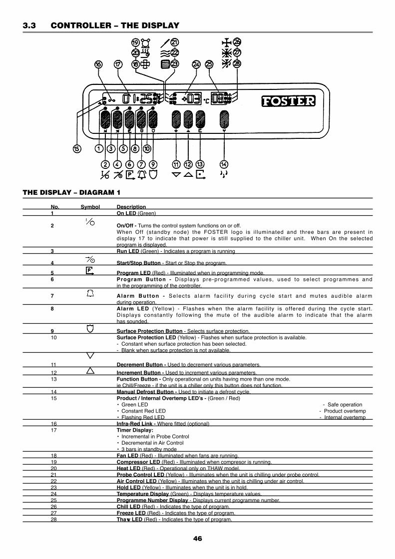
46
3.3 CONTROLLER – THE DISPLAY
THE DISPLAY – DIAGRAM 1
No. Symbol Description 1 On LED (Green)
2 On/Off - Turns the control system functions on or off. When Off (standby node) the FOSTER logo is i l luminated and three bars are present in display 17 to indicate that power is still supplied to the chiller unit. When On the selected program is displayed. 3 Run LED (Green) - Indicates a program is running
4 Start/Stop Button - Start or Stop the program.
5 Program LED (Red) - Illuminated when in programming mode. 6 Program Button - Displays pre-programmed values, used to select programmes and in the programming of the controller.
7 A larm But ton - Selec ts a la rm fac i l i t y dur ing cyc le s ta r t and mutes aud ib le a la rm during operation. 8 Alarm LED (Yel low) - Flashes when the alarm faci l i ty is offered during the cycle start. Displays constant ly fol lowing the mute of the audible alarm to indicate that the alarm has sounded.
9 Surface Protection Button - Selects surface protection. 10 Surface Protection LED (Yellow) - Flashes when surface protection is available. - Constant when surface protection has been selected. - Blank when surface protection is not available.
11 Decrement Button - Used to decrement various parameters.
12 Increment Button - Used to increment various parameters. 13 Function Button - Only operational on units having more than one mode. ie Chill/Freeze - if the unit is a chiller only this button does not function. 14 Manual Defrost Button - Used to initiate a defrost cycle. 15 Product / Internal Overtemp LED’s - (Green / Red) • Green LED - Safe operation • Constant Red LED - Product overtemp • Flashing Red LED - Internal overtemp 16 Infra-Red Link - Where fitted (optional) 17 Timer Display: • Incremental in Probe Control • Decremental in Air Control • 3 bars in standby mode 18 Fan LED (Red) - Illuminated when fans are running. 19 Compressor LED (Red) - Illuminated when compresor is running. 20 Heat LED (Red) - Operational only on THAW model. 21 Probe Control LED (Yellow) - Illuminates when the unit is chilling under probe control. 22 Air Control LED (Yellow) - Illuminates when the unit is chilling under air control. 23 Hold LED (Yellow) - Illuminates when the unit is in hold. 24 Temperature Display (Green) - Displays temperature values. 25 Programme Number Display - Displays current programme number. 26 Chill LED (Red) - Indicates the type of program. 27 Freeze LED (Red) - Indicates the type of program. 28 Thaw LED (Red) - Indicates the type of program.
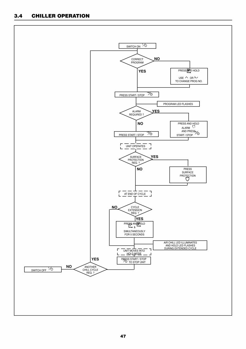
3.4 CHILLER OPERATION
47
YES
CORRECTPROGRAM
NO
SWITCH ON
ANOTHERCHILL CYCLE
REQ. ?
YES
NO
ALARMREQUIRED ?
SURFACEPROTECTION
REQ. ?
CYCLEEXTENSION
REQ. ?
PRESS AND HOLD
USE OR TO CHANGE PROG NO.
PRESS START / STOP
PROGRAM LED FLASHES
YES
NO PRESS AND HOLD
ALARM AND PRESS
START / STOP PRESS START / STOP
AT END OF CYCLE
UNIT OPERATES
NO
YES
YES
NO
SWITCH OFF
PRESSSURFACE
PROTECTION
PRESS AND HOLD &
SIMULTANEOUSLYFOR 5 SECONDS
UNIT MOVES INTOHOLD MODE
AIR CHILL LED ILLUMINATESAND HOLD LED FLASHES
DURING EXTENDED CYCLE
PRESS START / STOP TO STOP UNIT
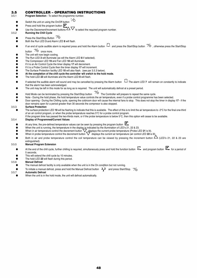
48
3.5 CONTROLLER – OPERATING INSTRUCTIONS3.5.1 Program Selection - To select the programme number.
● Switch the unit on using the On/Off button ● Press and hold the program button
● Use the Decrement/Increment buttons to select the required program number.3.5.2 Running the Chill Cycle
● Press the Start/Stop Button ● Both the Run LED 3 and Alarm LED 8 will flash.
● If an end of cycle audible alarm is required press and hold the Alarm button and press the Start/Stop button , otherwise press the Start/Stop
button once more. ● The unit will now begin cooling. ● The Run LED 3 will illuminate (as will the Alarm LED 8 if selected). ● The Compressor LED 19 and Fan LED 18 will illuminate. ● If it is an Air Control Cycle the timer display 17 will decrement. ● If it is a Probe Control Cycle then the timer display 17 will increment. ● The Surface Protection facility LED 10 will also flash. (see par 3.5.3 below). ● At the completion of the chill cycle the controller will switch to the hold mode. ● The hold LED 23 will illuminate and the Alarm LED 8 will flash.
● If selected the audible alarm will sound and may be cancelled by pressing the Alarm button The alarm LED 7 will remain on constantly to indicate that the alarm has been acknowledged.
● The unit may be left in this mode for as long as is required. The unit will automatically defrost at a preset period.
● Hold Mode can be terminated by pressing the Start/Stop button The Controller will prepare to repeat the same cycle. ● Note - During the hold phase, the hold temperature value controls the air temperature, even if a probe control programme has been selected. ● Door opening - During the Chilling cycle, opening the coldroom door will cause the internal fans to stop. This does not stop the timer in display 17 - if the
door remains open for a period greater than 30 seconds the compresor is also stopped.3.5.3 Surface Protection ● The surface protection LED 10 will be flashing to indicate that this is available. The effect of this is to limit the air temperature to -2°C for the final one-third
of an air control program, or when the probe temperature reaches 5°C for a probe control program. If the program time has passed the two-thirds mark, or if the probe temperature is below 5°C, then this option will cease to be available.3.5.4 Display of Programmed/Current Values
● At any time, the pre-defined temperature values can be seen by pressing the program button ● When the unit is running, the temperature in the display is indicated by the illumination of LED’s 21, 22 & 23. ● When in air temperature control the decrement button displays the current probe temperature (Probe LED 21 is lit). ● When in probe temperature control the decrement button displays the current air temperature (air control LED 22 is lit).
● Both in air and probe temperature control the coil temperature can be viewed by pressing the increment button (LED’s 21, 22 & 23 are extinguished).
3.5.5 Manual Program Extension
● At the end of the chill cycle, further chilling is required, simultaneously press and hold the function button and program button for a period of 5 seconds.
● This will extend the chill cycle by 10 minutes. ● The hold LED 23 will flash during this period.3.5.6 Manual Defrost ● The manual defrost facility is only available when the unit is in the On condition but not running.
● To initiate a manual defrost, press and hold the Manual Defrost button and press Start/Stop. 3.5.7 Automatic Defrost ● When the unit is in the hold mode, the unit will defrost automatically.
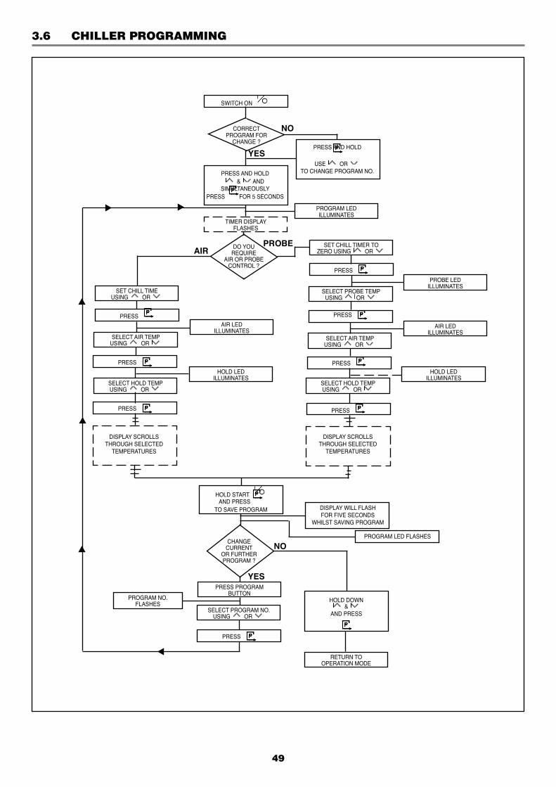
49
3.6 CHILLER PROGRAMMING
CORRECTPROGRAM FOR
CHANGE ?
SWITCH ON
YES
NO
PROGRAM LEDILLUMINATES
PRESS AND HOLD
USE OR TO CHANGE PROGRAM NO.PRESS AND HOLD
& ANDSIMULTANEOUSLY
PRESS FOR 5 SECONDS
TIMER DISPLAYFLASHES
DO YOUREQUIRE
AIR OR PROBECONTROL ?
PROBEAIR
SET CHILL TIMER TOZERO USING OR
PROBE LEDILLUMINATES
SELECT PROBE TEMPUSING OR
AIR LEDILLUMINATES
HOLD LEDILLUMINATES
SELECT AIR TEMPUSING OR
SELECT HOLD TEMPUSING OR
SELECT AIR TEMPUSING OR
SELECT HOLD TEMPUSING OR
SET CHILL TIMEUSING OR
AIR LEDILLUMINATES
HOLD LEDILLUMINATES
DISPLAY SCROLLSTHROUGH SELECTED
TEMPERATURES
DISPLAY SCROLLSTHROUGH SELECTED
TEMPERATURES
PRESS
PRESS PRESS
PRESS
PRESS
PRESS
PRESS
PRESS PROGRAMBUTTON
SELECT PROGRAM NO.USING OR
PRESS
PROGRAM NO.FLASHES
HOLD DOWN &
AND PRESS
RETURN TOOPERATION MODE
CHANGECURRENT
OR FURTHERPROGRAM ?
DISPLAY WILL FLASH FOR FIVE SECONDS
WHILST SAVING PROGRAM
YES
NO
HOLD START AND PRESS
TO SAVE PROGRAM
PROGRAM LED FLASHES
50
3.7 CHILL CYCLE SETTING ● This section covers programming the blast chiller. ● Setting is accessed by simultaneously pressing three buttons to prevent tampering or accidential programming changes. This sequence is as follows:3.7.1 Select the program for change - ref: 3.5.1.
3.7.2 Hold down the decrement/increment buttons and simultaneously press the program button until the Program LED illuminates. The controller is now in programming mode. The Timer display will flash.
NOTE: If no changes are made during a programming operation for 2 minutes, the controller will reset itself automatically for normal operation.
3.7.3 Set the Timer -
a) For Air Temperature Control, use the increment / decrement buttons to select the desired chill time.
b) For Probe Temperature Control set the Timer display to zero using the increment / decrement buttons
3.7.4 For Air Temperature Control - Press the Program button The Air Control LED 22 will illuminate and the air temperature will flash.
● Using the increment / decrement buttons select the Air temperature required for chilling.
● Press the Program button - the Hold LED 23 will illuminate and the hold temperature will flash.
Using the increment / decrement buttons select the Hold temperature.
● Press the Program button - the Temperature Display will alternatively flash between the Air Temperature and the Hold Temperature showing the selected values.
Go to 3.7.6
3.7.5 For Probe Temperature Control - Press the Program button .... The Probe Control LED 21 will illuminate and the Probe Temperature will flash.
Using the increment / decrement buttons select the desired probe temperature.
● Press the Program button - the Air Control LED 22 will illuminate and the Air Temperature will flash.
Using the increment / decrement buttons select the internal Air Temperature during chilling.
● Press the Progam button - the hold LED will illuminate and the hold temperature will flash.
Using the increment / decrement buttons select the desired Hold Temperature.
● Press the Program button - the temperature display 24 will alternate between probe, air and hold temperature showing the selected values.
3.7.6 To save the selected values, press and hold the Start/Stop button and press the Program button All displays will flash for 5 seconds.3.7.7 If the current program has been incorrectly entered or programming of further channels is desired press the Program button
- the Program number will flash - display 25.
Using the increment / decrement buttons select the Program number to be changed.
Press the Program button The Timer display will flash. Continue from 3.7.3
3.7.8 To exit the programming mode, hold down the increment / decrement buttons , and press the Program button
3.8 FAILURE SITUATIONS ● Power Failure - In the event of a power failure the unit will stop functioning. On resupply, the unit will resume from its condition at the point of failure. ● If the failure causes the product to deviate from its desired temperature control limits, products alarms will be activated. ● Probe Failure - In general this will not stop the unit from running. However, depending of the nature of the fault the operation of the unit may not be correct
and the chill cycle may need to be restarted. ● Failure/Disconnection or severing of a Probe will show as a PF symbol in display 24. ● Overtemperature ● Fans - if the fans overheat, the individual fan thermal overload will cut out the motor to prevent accidential damage. ● Heaters - should the internal temperature exceed a preset value due to heater control failure, the overtemperature probe will cause a shut down of the
blast chiller. ● Should this fail to operate, a safety stat will terminate all electical supply.
3.9 TEST OUTPUTS3.9.1 Test Outputs - This mode allows the installer or service engineer to activate any of the relays for commisioning or testing. ● Ensure that the display is off. Three bars will be displayed in 17.
● Press and hold the increment, Decrement and Funct ion buttons together and then press the On/Off button
Display will show ‘tESt’. ● Display 25 shows the currently selected relay output and display 24 shows the state fo that relay (On or Off). Select the required relay by pressing the
Function button Switch the relay on or off by pressing the Increment or Decrement buttons, respectively ● There are seven relays, five on the Tuscan and two on the auxilliary relay board. These are allocated as follows: No: Description: Neon: 1 Compressor 1 1 2 High Speed Fan 3 3 Low Speed Fan 4 4 Defrost 5 5 Alarm 7 6 Compressor 2 2 7 Heat 6
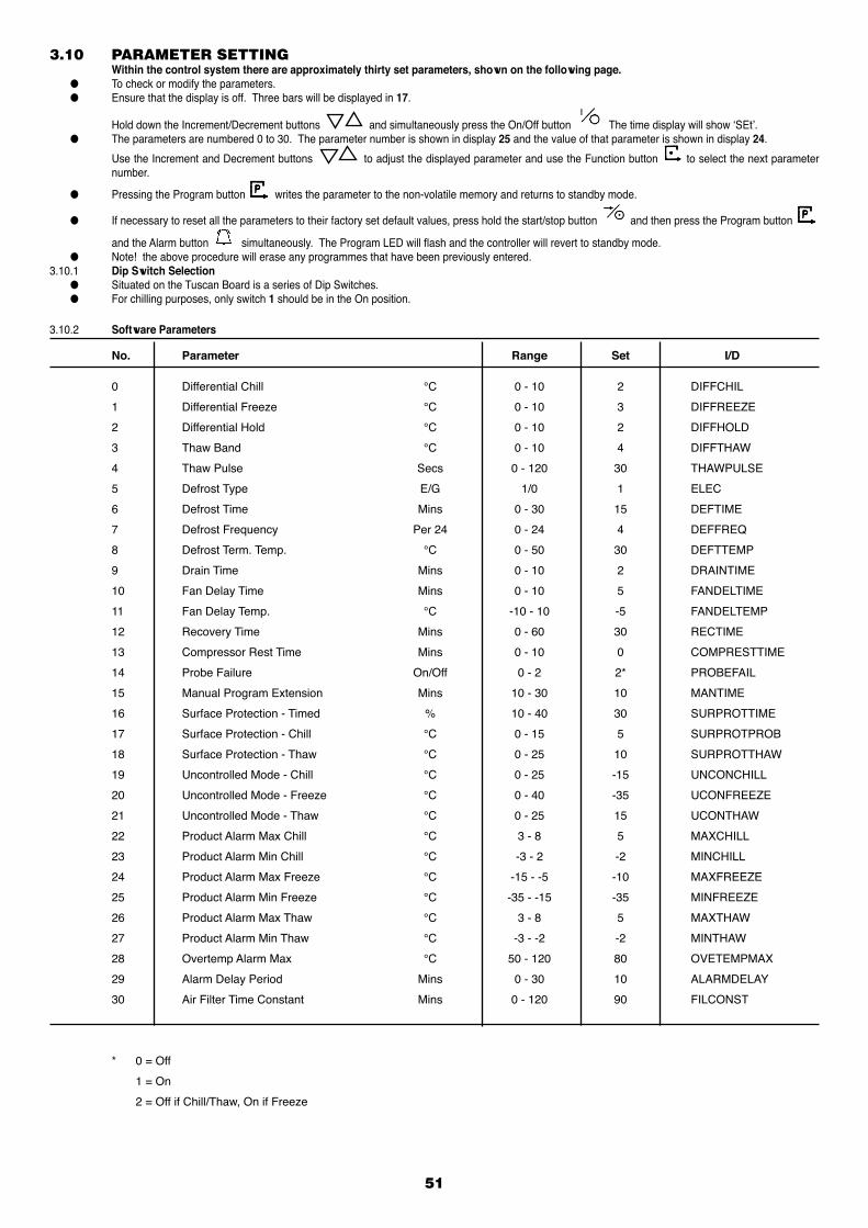
51
3.10 PARAMETER SETTING Within the control system there are approximately thirty set parameters, shown on the following page. ● To check or modify the parameters. ● Ensure that the display is off. Three bars will be displayed in 17.
Hold down the Increment/Decrement buttons and simultaneously press the On/Off button The time display will show ‘SEt’. ● The parameters are numbered 0 to 30. The parameter number is shown in display 25 and the value of that parameter is shown in display 24.
Use the Increment and Decrement buttons to adjust the displayed parameter and use the Function button to select the next parameter number.
● Pressing the Program button writes the parameter to the non-volatile memory and returns to standby mode.
● If necessary to reset all the parameters to their factory set default values, press hold the start/stop button and then press the Program button
and the Alarm button simultaneously. The Program LED will flash and the controller will revert to standby mode. ● Note! the above procedure will erase any programmes that have been previously entered.3.10.1 Dip Switch Selection ● Situated on the Tuscan Board is a series of Dip Switches. ● For chilling purposes, only switch 1 should be in the On position.
3.10.2 Software Parameters
No. Parameter Range Set I/D
0 Differential Chill °C 0 - 10 2 DIFFCHIL
1 Differential Freeze °C 0 - 10 3 DIFFREEZE
2 Differential Hold °C 0 - 10 2 DIFFHOLD
3 Thaw Band °C 0 - 10 4 DIFFTHAW
4 Thaw Pulse Secs 0 - 120 30 THAWPULSE
5 Defrost Type E/G 1/0 1 ELEC
6 Defrost Time Mins 0 - 30 15 DEFTIME
7 Defrost Frequency Per 24 0 - 24 4 DEFFREQ
8 Defrost Term. Temp. °C 0 - 50 30 DEFTTEMP
9 Drain Time Mins 0 - 10 2 DRAINTIME
10 Fan Delay Time Mins 0 - 10 5 FANDELTIME
11 Fan Delay Temp. °C -10 - 10 -5 FANDELTEMP
12 Recovery Time Mins 0 - 60 30 RECTIME
13 Compressor Rest Time Mins 0 - 10 0 COMPRESTTIME
14 Probe Failure On/Off 0 - 2 2* PROBEFAIL
15 Manual Program Extension Mins 10 - 30 10 MANTIME
16 Surface Protection - Timed % 10 - 40 30 SURPROTTIME
17 Surface Protection - Chill °C 0 - 15 5 SURPROTPROB
18 Surface Protection - Thaw °C 0 - 25 10 SURPROTTHAW
19 Uncontrolled Mode - Chill °C 0 - 25 -15 UNCONCHILL
20 Uncontrolled Mode - Freeze °C 0 - 40 -35 UCONFREEZE
21 Uncontrolled Mode - Thaw °C 0 - 25 15 UCONTHAW
22 Product Alarm Max Chill °C 3 - 8 5 MAXCHILL
23 Product Alarm Min Chill °C -3 - 2 -2 MINCHILL
24 Product Alarm Max Freeze °C -15 - -5 -10 MAXFREEZE
25 Product Alarm Min Freeze °C -35 - -15 -35 MINFREEZE
26 Product Alarm Max Thaw °C 3 - 8 5 MAXTHAW
27 Product Alarm Min Thaw °C -3 - -2 -2 MINTHAW
28 Overtemp Alarm Max °C 50 - 120 80 OVETEMPMAX
29 Alarm Delay Period Mins 0 - 30 10 ALARMDELAY
30 Air Filter Time Constant Mins 0 - 120 90 FILCONST
* 0 = Off
1 = On
2 = Off if Chill/Thaw, On if Freeze
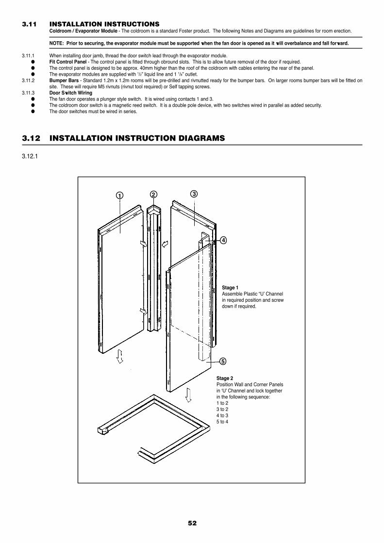
52
3.12 INSTALLATION INSTRUCTION DIAGRAMS
3.12.1
Stage 2Position Wall and Corner Panelsin ‘U’ Channel and lock togetherin the following sequence:1 to 23 to 24 to 35 to 4
Stage 1Assemble Plastic “U’ Channelin required position and screwdown if required.
1 2 3
4
5
3.11 INSTALLATION INSTRUCTIONS Coldroom / Evaporator Module - The coldroom is a standard Foster product. The following Notes and Diagrams are guidelines for room erection.
NOTE: Prior to securing, the evaporator module must be supported when the fan door is opened as it will overbalance and fall forward.
3.11.1 When installing door jamb, thread the door switch lead through the evaporator module. ● Fit Control Panel - The control panel is fitted through obround slots. This is to allow future removal of the door if required. ● The control panel is designed to be approx. 40mm higher than the roof of the coldroom with cables entering the rear of the panel. ● The evaporator modules are supplied with 1/2” liquid line and 1 1/8” outlet.3.11.2 Bumper Bars - Standard 1.2m x 1.2m rooms will be pre-drilled and rivnutted ready for the bumper bars. On larger rooms bumper bars will be fitted on
site. These will require M5 rivnuts (rivnut tool required) or Self tapping screws.3.11.3 Door Switch Wiring ● The fan door operates a plunger style switch. It is wired using contacts 1 and 3. ● The coldroom door switch is a magnetic reed switch. It is a double pole device, with two switches wired in parallel as added security. ● The door switches must be wired in series.
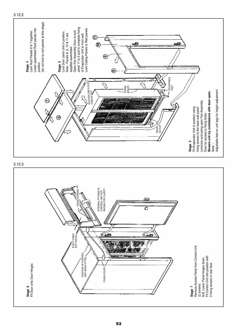
53
3.12.2
3.12.3
Stag
e 6
Fit D
oor o
nto
Doo
r Hin
ges
Stag
e 7
Rem
ove
Acce
ss P
anel
from
Con
trol U
nit
(2 s
crew
s)N
.B. L
ower
Pan
el h
inge
s do
wn.
Fit C
ontro
l Uni
t int
o po
sitio
n w
ith5
fixin
g sc
rew
s in
rear
face
FIXI
NG
HO
LES
INTE
RN
AL F
ITTI
NG
S IN
CO
NTR
OL
UN
IT N
OT
SHO
WN
FO
R C
LAR
ITY
POSI
TIO
N O
F C
ON
TRO
LU
NIT
WH
EN F
ITTE
D
FIXI
NG
SC
REW
S
ELEC
T C
ABLE
EXIT
HO
LES
Stag
e 3
Fit E
vapo
rato
r Uni
t in
posi
tion
usin
gfix
ing
scre
ws
to th
e ba
ck w
all p
anel
(uns
crew
and
sw
ing
open
Fan
Ass
embl
yD
oor f
or a
cces
s to
fixi
ng h
oles
-B
ewar
e un
it m
y ov
erba
lanc
e w
ith d
oor o
pen.
Not
e: -
Adju
stab
le fe
et o
n un
it le
gs fo
r hei
ght a
djus
tmen
t
Stag
e 5
Lock
Doo
r Jam
b U
nit i
n po
sitio
n.N
ote
- Pan
els
8, 9
, 10
& 11
are
supp
lied
asse
mbl
ed.
Ope
n Fa
n As
sem
bly
Doo
r to
lock
pane
l 11
to 5
and
to c
ompl
ete
fixin
gof
Eva
pora
tor U
nit t
o fro
nt w
all.
Lock
Cei
ling
Pane
ls to
Wal
l pan
els
Stag
e 4
Lock
Roo
f Pan
els
6 &
7 to
geth
er.
Low
er a
ssem
bled
Roo
f pan
els
into
posi
tion.
(do
not l
ock
to ro
of p
anel
s at
this
sta
ge)
6
7
8
9
1011
ADJU
STAB
LE
FEET
DR
AIN
LIN
EO
UTL
ET
FIXI
NG
HO
LES
SUC
TIO
N L
INE
& EL
ECT
CAB
LES
EXIT
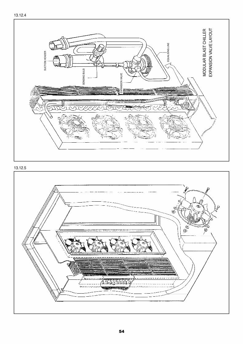
54
13.12.4
13.12.5EQ
UAL
ISIN
G L
INE
MO
DU
LAR
BLA
ST C
HIL
LER
EXPA
NSI
ON
VAL
VE L
AYO
UT
EXPA
NSI
ON
VAL
VE
SEN
SIN
G B
ULBSU
CTI
ON
HEA
DER
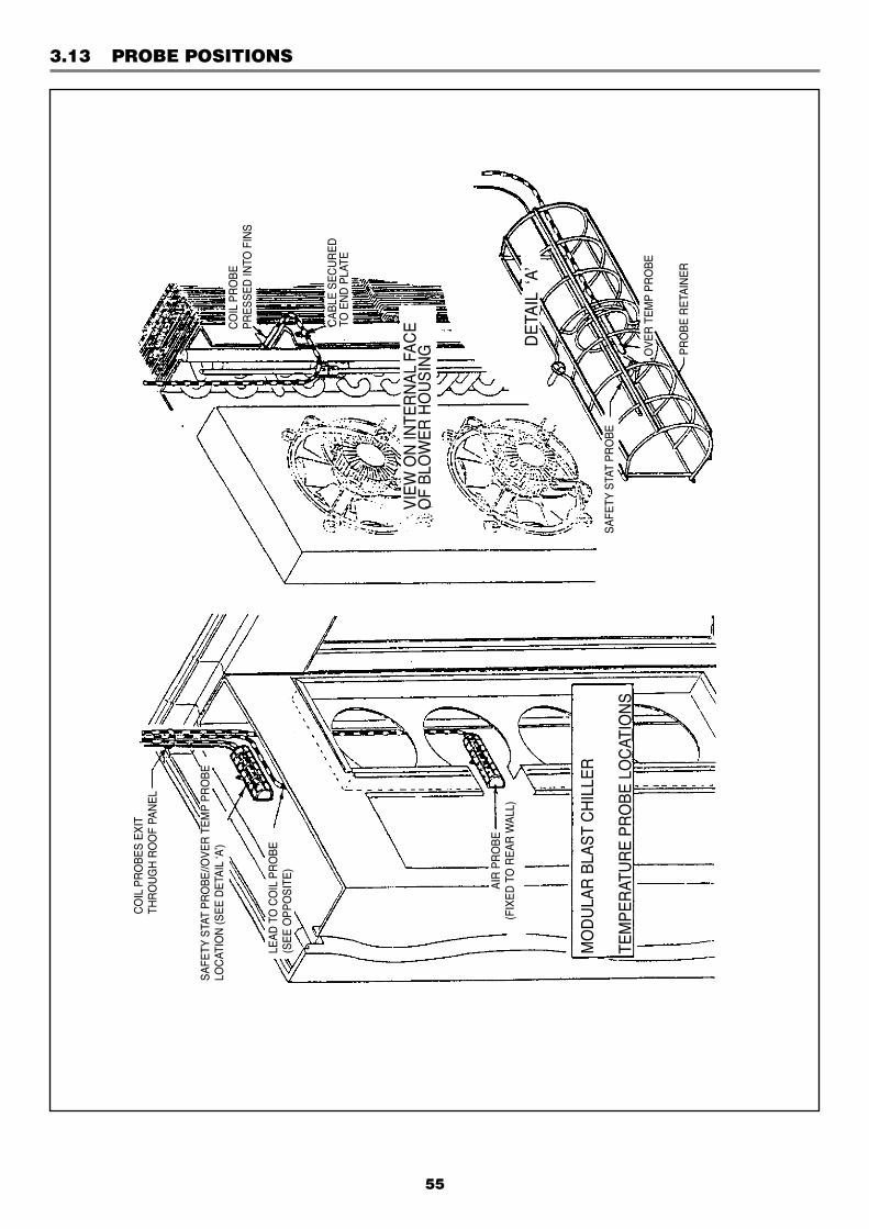
55
3.13 PROBE POSITIONS
CO
IL P
RO
BES
EXIT
THR
OU
GH
RO
OF
PAN
EL
SAFE
TY S
TAT
PRO
BE//O
VER
TEM
P PR
OBE
LOC
ATIO
N (S
EE D
ETAI
L ‘A
’)
LEAD
TO
CO
IL P
RO
BE(S
EE O
PPO
SITE
)
AIR
PR
OBE
(FIX
ED T
O R
EAR
WAL
L)
MO
DU
LAR
BLA
ST C
HIL
LER
TEM
PER
ATU
RE
PRO
BE L
OC
ATIO
NS
CO
IL P
RO
BEPR
ESSE
D IN
TO F
INS
CAB
LE S
ECU
RED
TO E
ND
PLA
TE
DET
AIL
‘A’
VIEW
ON
INTE
RN
AL F
ACE
OF
BLO
WER
HO
USI
NG
SAFE
TY S
TAT
PRO
BE
PRO
BE R
ETAI
NER
OVE
R T
EMP
PRO
BE