Embed Size (px)
Citation preview
Tampere University of Technology
Modified Thick Thermal Barrier Coatings
CitationAhmaniemi, A. S. . S. (2004). Modified Thick Thermal Barrier Coatings. (Tampere University of Technology.Publication; Vol. 473). Tampere University of Technology.
Year2004
VersionPublisher's PDF (version of record)
Link to publicationTUTCRIS Portal (http://www.tut.fi/tutcris)
Take down policyIf you believe that this document breaches copyright, please contact [email protected], and we will remove access tothe work immediately and investigate your claim.
Download date:06.07.2018
Tampereen teknillinen yliopisto. Julkaisu 473 Tampere University of Technology. Publication 473 Antti Samuli (Samppa) Ahmaniemi Modified Thick Thermal Barrier Coatings Thesis for the degree of Doctor of Technology to be presented with due permission for public examination and criticism in Konetalo Building, Auditorium K1702, at Tampere University of Technology, on the 28th of May 2004, at 12 noon. Tampereen teknillinen yliopisto - Tampere University of Technology Tampere 2004

ISBN 952-15-1181-8 (printed) ISBN 952-15-1553-8 (PDF) ISSN 1459-2045
PREFACE
The work for this thesis was mainly carried out during the years 1999-2003 in the Tampere University of Technology, Institute of Materials Science (TUT/IMS). The supervisor of the thesis was professor Tapio Mäntylä. I want to thank professor Mäntylä for all his guidance and for giving me the opportunity to prepare the thesis at TUT/IMS. I am grateful to professor Petri Vuoristo with whom I worked closely for years in TUT/IMS, too. During those years he always deepened my knowledge of coatings and coating technologies. Many thanks also to co-authors from TUT/IMS (Dr. Minnamari Vippola, M. Sc. Jari Tuominen) as well as to the technical and assistant personnel (Mikko Kylmälahti, Ulla Männikkö, Sari Iltanen, Mari Honkanen, Katri Kosme). I completed part of the work at the University of Trento, Italy (08/2001-07/2002). I am grateful especially to Dr. Luca Lutterotti, Dr. Rosa Di Maggio and professor Roberto Dal Maschio who gave me the opportunity to work at the University of Trento. They all supported me scientifically, but also helped me with the language and the Italian way of living. I thank all the organisations (IVO Säätiö, Henry Fordin säätiö, Ehnrothin säätiö, Tampereen kaupunki and Kaupallisten ja teknillisten tieteiden säätiö) that awarded me the funding for this exchange period in Italy. The work with thick thermal barrier coatings in diesel engines started in the project “Development of the wall construction of the combustion chamber in a Diesel engine”. The project was funded by National Technology Agency (Tekes), Wärtsilä Technologies Oy and Patria Finavitec Oy. The project lasted for three years (12/1999-08/2002) and was coordinated by the Internal Combustion Engine Laboratory, Helsinki University of Technology (HUT/ICELAB). Co-operation with HUT/ICELAB continued in the Extreme Value Engine (EVE) project. The EVE project (06/2000-12/2003) was funded by the Academy of Finland. I thank all the financial supporters related to these projects. I would like also to thank the personnel of the HUT/ICELAB for their fruitful, interdisciplinary co-operation in the field of diesel engines and materials science. In 1999-2003 TUT/IMS took part in the COST 522 Program (Ultra Efficient, Low Emission Power Plant/Gas Turbine Group) in which the TTBCs were considered more from the standpoint of gas turbines. Here I thank Federico Cernuschi (CESI, Italy), Carlo Gualco (Ansaldo Richerche, Italy) and Robert Vassen (Forschungszentrum Jülich GmbH, Germany) for their contributions to our joint studies. I thank also the personnel of the Institute of Materials Science and especially the people in the Surface Engineering Laboratory where the atmosphere is both scientific and relaxing. Last but not least I thank my wife Riikka for her positive attitude towards my work. Finally I am grateful to my daughter Ella who keeps my feet on the ground by saying once in a while "Daddy, you just an average engineer”. Muurame, 16 of February, 2004 Samppa Ahmaniemi

ABSTRACT
This thesis studies the microstructures of modified zirconia based thick thermal barrier coatings as well as their properties. Plasma sprayed yttria stabilised zirconia (8Y2O3-ZrO2) was the basic reference coating, but magnesia (MgO) and ceria (CeO2) stabilised zirconia coatings were also studied. Coating microstructures were mainly modified by post treatments, such as phosphate based sealing treatments and laser glazing. These procedures were carried out in order to improve particular coating properties such as erosion resistance, thermal cycling resistance and hot corrosion resistance. The work concentrated mainly on optimising the coating modification procedures, performing detailed coating characterisation, determining the coating mechanical and thermal properties and testing their high temperature properties in hot corrosion and thermal cycling experiments. The modification procedures changed coating microstructures near the surface. Phosphate sealants penetrated approximately 300-400 µm into the coating microcracks and pores reducing the open porosity by 24-48 % depending on the coating material. It was found that the sealant improved the cohesion of the splat boundaries by adhesive binding and chemical bonding mechanisms. In laser glazing it was possible to control the melting of the ceramic coating surface. Optimal thickness of the melted layer was 50-150 µm leading to a dense surface layer with specific vertical macrocrack structure. Modification processes strongly affected on the coating mechanical and wear properties. Microhardness of the phosphate sealed coatings was increased by 15-55 % and as much as 70-100 % in the case on laser-glazed coatings. The strengthening effect of the phosphate sealing was clearly seen in the four-point bending tests, where the modulus of rupture in bending (RB) of the 8Y2O3-ZrO2 coating was increased by more than 200 %. At the same time, the bending modulus (EB) of the phosphate sealed coating was almost eight times higher than the as-sprayed reference coating. In the laser-glazed 8Y2O3-ZrO2 coating the modulus of rupture in bending was one fourth and the bending modulus only one fifth that of the as-sprayed coating. Erosion resistance of the 22MgO-ZrO2 and 8Y2O3-ZrO2 coatings was improved by 65-70 % due to the phosphate based sealing treatment. The average improvement in the laser-glazed 8Y2O3-ZrO2 coating was 35 %. Thermal conductivity (k(T)) of all studied zirconia based coatings at a temperature range of RT-1250oC was more than doubled by the phosphate sealing. Sealing also weakened the high temperature phase stability of the 8Y2O3-ZrO2 coating at temperatures over 1000oC. Laser glazing had only a minor effect on the thermal properties of the coating. Depending on the macrocrack structure and its orientation, laser glazing either slightly raised or slightly lowered thermal conductivity. Modification processes had no clear beneficial effect on coating hot corrosion resistance, when exposed in air to a NaSO4-V2O5 based deposit at 650, 750, and 850oC for 48-1000 hours. The penetration of melt deposit into the phosphate sealed coatings was lowered in some degree if compared to the as-sprayed coatings. However, the phosphate sealed coatings failed in hot corrosion tests mainly because of the strong compressive stresses generated during the test. The compressive stresses were mainly induced when tetragonal and cubic zirconia phases transformed to monoclinic zirconia. The microstructure of the laser-glazed coatings was not optimal considering the hot corrosion test method (melt deposit exposure). The melt deposit penetrated through the vertical cracks in the laser-glazed top layer and affected the coating structure much as it did in the case of as-sprayed coatings. The laser-glazed zone itself at the top of the coating was rather unaffected.

Thermal cycling resistance of the 8Y2O3-ZrO2 coating was lowered by the phosphate sealing treatment. The reasons for the deterioration of the strain tolerance of the phosphate sealed coating were the increased elastic modulus due to better cohesion of splats and compressive internal stresses. Thermal cycling behaviour of the laser-glazed 8Y2O3-ZrO2 coatings was superior compared to the reference coating. Reduced elastic modulus due to the macrocracks made the laser-glazed coating much more strain tolerant. .
TABLE OF CONTENTS
PREFACE............................................................................................................................1
ABSTRACT.........................................................................................................................3
TABLE OF CONTENTS ......................................................................................................5
LIST OF INCLUDED PUBLICATIONS................................................................................9
LIST OF SYMBOLS AND ABBREVIATIONS...................................................................11
1. INTRODUCTION ........................................................................................................13
1.1 Applications of thermal barrier coatings...............................................................13
1.1.1 Gas turbine...................................................................................................13
1.1.2 Diesel engine................................................................................................14
1.2 TBC manufacturing processes ............................................................................15
1.3 TBC structure and design....................................................................................16
1.4 TBC materials......................................................................................................16
1.4.1 Partially stabilised zirconias .........................................................................17
1.4.2 Other TBC materials.....................................................................................18
1.5 Thick thermal barrier coatings .............................................................................18
1.5.1 Demand for thicker coatings.........................................................................18
1.5.2 Drawbacks of TTBCs ...................................................................................19
1.5.3 Microstructural modifications of TBCs ..........................................................20
1.6 Aims of the study.................................................................................................23
2. EXPERIMENTAL PROCEDURES .............................................................................24
2.1 Studied materials and coating modification procedures ......................................24
2.1.1 Reference coatings and substrate materials ................................................24
2.1.2 Phosphate based sealing procedures ..........................................................25
2.1.3 Laser glazing procedure...............................................................................26
2.1.4 Other modification processes.......................................................................26
2.2 Microstructural characterisation methods ............................................................27
2.2.1 Microscopy ...................................................................................................27
2.2.2 X-ray diffraction ............................................................................................28
2.2.3 Porosity and bulk density determination.......................................................28
2.3 Mechanical and wear property determination......................................................29
2.3.1 Microhardness..............................................................................................29
2.3.2 Modulus of rupture in bending and bending modulus...................................29
2.3.3 Erosion resistance........................................................................................30
2.3.4 Abrasion resistance......................................................................................30
2.4 Thermal property determination ..........................................................................30
2.4.1 Thermal expansion.......................................................................................30
2.4.2 Thermal diffusivity ........................................................................................30
2.4.3 Specific heat.................................................................................................30
2.4.4 Thermal conductivity ....................................................................................31
2.5 Hot corrosion testing............................................................................................31
2.6 Thermal cycling testing........................................................................................32
3. RESULTS AND DISCUSSION...................................................................................34
3.1 Microstructural characterisation...........................................................................34
3.1.1 Surface densification of modified coatings ...................................................34
3.1.2 Characteristic microstructure of the phosphate sealed coatings ..................37
3.1.3 Characteristic microstructure of the laser-glazed coatings ...........................38
3.1.4 Phase structures ..........................................................................................41
3.2 Mechanical and wear properties..........................................................................42
3.2.1 Microhardness..............................................................................................43
3.2.2 Elastic properties..........................................................................................43
3.2.3 Residual stresses .........................................................................................44
3.2.4 Wear properties............................................................................................46
3.3 Thermophysical properties ..................................................................................47
3.3.1 Thermal expansion.......................................................................................47
3.3.2 Microstructure and phase structure of the heat treated coatings..................50
3.3.3 Thermal conductivity ....................................................................................51
3.4 Hot corrosion properties ......................................................................................52
3.4.1 Melt deposit penetration into the coatings ....................................................52
3.4.2 Zirconia destabilization and corrosion reactions...........................................59
3.4.3 Stress generation in the hot corrosion exposed coatings .............................61
3.4.4 Conclusions of the hot corrosion experiments..............................................62
3.5 Thermal cycling properties ..................................................................................62
3.5.1 Test series 1.................................................................................................63
3.5.2 Test series 2.................................................................................................65
3.5.3 Test series 3.................................................................................................66
3.5.4 Discussion of the test results and failure modes ..........................................67
4. CONCLUDING REMARKS ........................................................................................69
REFERENCES ..................................................................................................................72


LIST OF INCLUDED PUBLICATIONS
This thesis consists of a summary of main results and six enclosed original publications I-VI. Publication I S. Ahmaniemi J. Tuominen, P. Vuoristo and T. Mäntylä: Sealing Procedures for Thick Thermal Barrier Coatings, Journal of Thermal Spray Technology 11 (2002) 320-332. Publication II S. Ahmaniemi, P. Vuoristo and T. Mäntylä: Improved Sealing Treatments for Thick Thermal Barrier Coatings, Surface and Coatings Technology 151-152 (2002) 412-417. Publication III S. Ahmaniemi, M. Vippola, P. Vuoristo, T. Mäntylä, F. Cernuschi, L. Lutterotti, Modified Thick Thermal Barrier Coatings: Microstructural Characterization, Journal of the European Ceramic Society 24 (2004) 2247-2258. Publication IV S. Ahmaniemi, P. Vuoristo, T. Mäntylä, F. Cernuschi, L. Lorenzoni, Modified Thick Thermal Barrier Coatings: Thermophysical Characterization, Journal of the European Ceramic Society 24 (2004) 2669–2679. Publication V S. Ahmaniemi, P. Vuoristo, T. Mäntylä, Mechanical and Elastic Properties of Modified Thick Thermal Barrier Coatings, Materials Science and Engineering A 366/1 (2004) 175-182. Publication VI S. Ahmaniemi, P. Vuoristo, T. Mäntylä, C. Gualco, A. Bonadei, R. Di Maggio, Thermal Cycling Resistance of Modified Thick Thermal Barrier Coatings. Surface and Coatings Technology (2004). In print. Author's contribution S. A. was the main researcher and writer of all the publications. He prepared the test matrixes and schedules; performed the specimen preparation, characterisation and testing; analysed the results and prepared the manuscripts. However, the co-authors were essential in following tasks: M. Sc. Jari Tuominen assisted in preparation and optimisation of the laser glazing process. In publication III M. Vippola performed the transmission electron microscopy studies. In publication IV F. Cernuschi and L. Lorenzoni carried out the thermal diffusivity and differential scanning calorimetry measurements in CESI (Segrate, Italy).

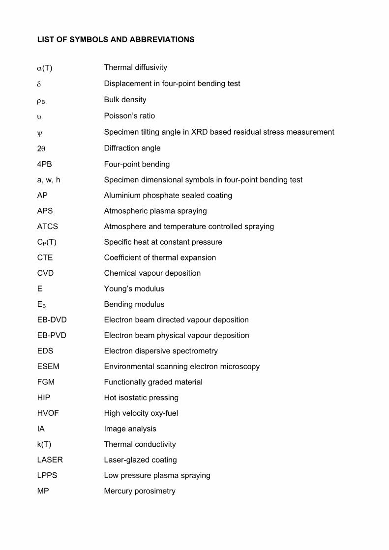
LIST OF SYMBOLS AND ABBREVIATIONS
α(T) Thermal diffusivity
δ Displacement in four-point bending test
ρB Bulk density
υ Poisson’s ratio
ψ Specimen tilting angle in XRD based residual stress measurement
2θ Diffraction angle
4PB Four-point bending
a, w, h Specimen dimensional symbols in four-point bending test
AP Aluminium phosphate sealed coating
APS Atmospheric plasma spraying
ATCS Atmosphere and temperature controlled spraying
CP(T) Specific heat at constant pressure
CTE Coefficient of thermal expansion
CVD Chemical vapour deposition
E Young’s modulus
EB Bending modulus
EB-DVD Electron beam directed vapour deposition
EB-PVD Electron beam physical vapour deposition
EDS Electron dispersive spectrometry
ESEM Environmental scanning electron microscopy
FGM Functionally graded material
HIP Hot isostatic pressing
HVOF High velocity oxy-fuel
IA Image analysis
k(T) Thermal conductivity
LASER Laser-glazed coating
LPPS Low pressure plasma spraying
MP Mercury porosimetry
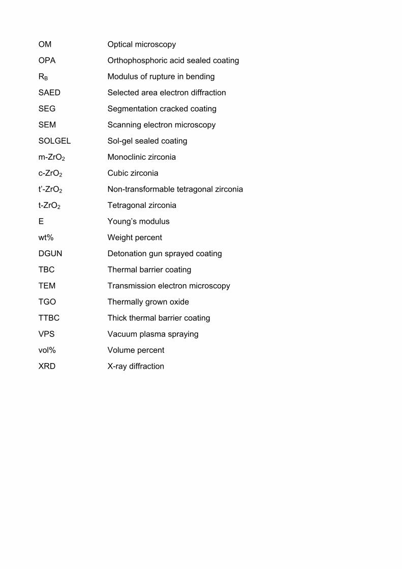
OM Optical microscopy
OPA Orthophosphoric acid sealed coating
RB Modulus of rupture in bending
SAED Selected area electron diffraction
SEG Segmentation cracked coating
SEM Scanning electron microscopy
SOLGEL Sol-gel sealed coating
m-ZrO2 Monoclinic zirconia
c-ZrO2 Cubic zirconia
t’-ZrO2 Non-transformable tetragonal zirconia
t-ZrO2 Tetragonal zirconia
E Young’s modulus
wt% Weight percent
DGUN Detonation gun sprayed coating
TBC Thermal barrier coating
TEM Transmission electron microscopy
TGO Thermally grown oxide
TTBC Thick thermal barrier coating
VPS Vacuum plasma spraying
vol% Volume percent
XRD X-ray diffraction
13
1. INTRODUCTION
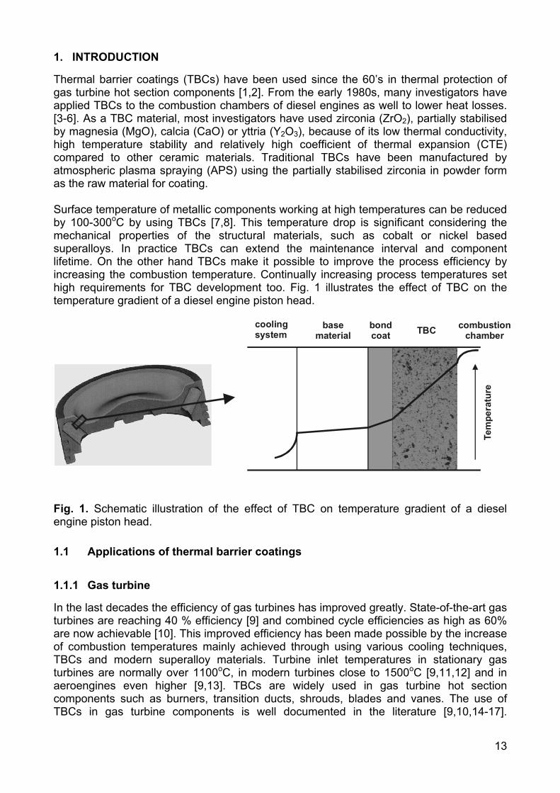
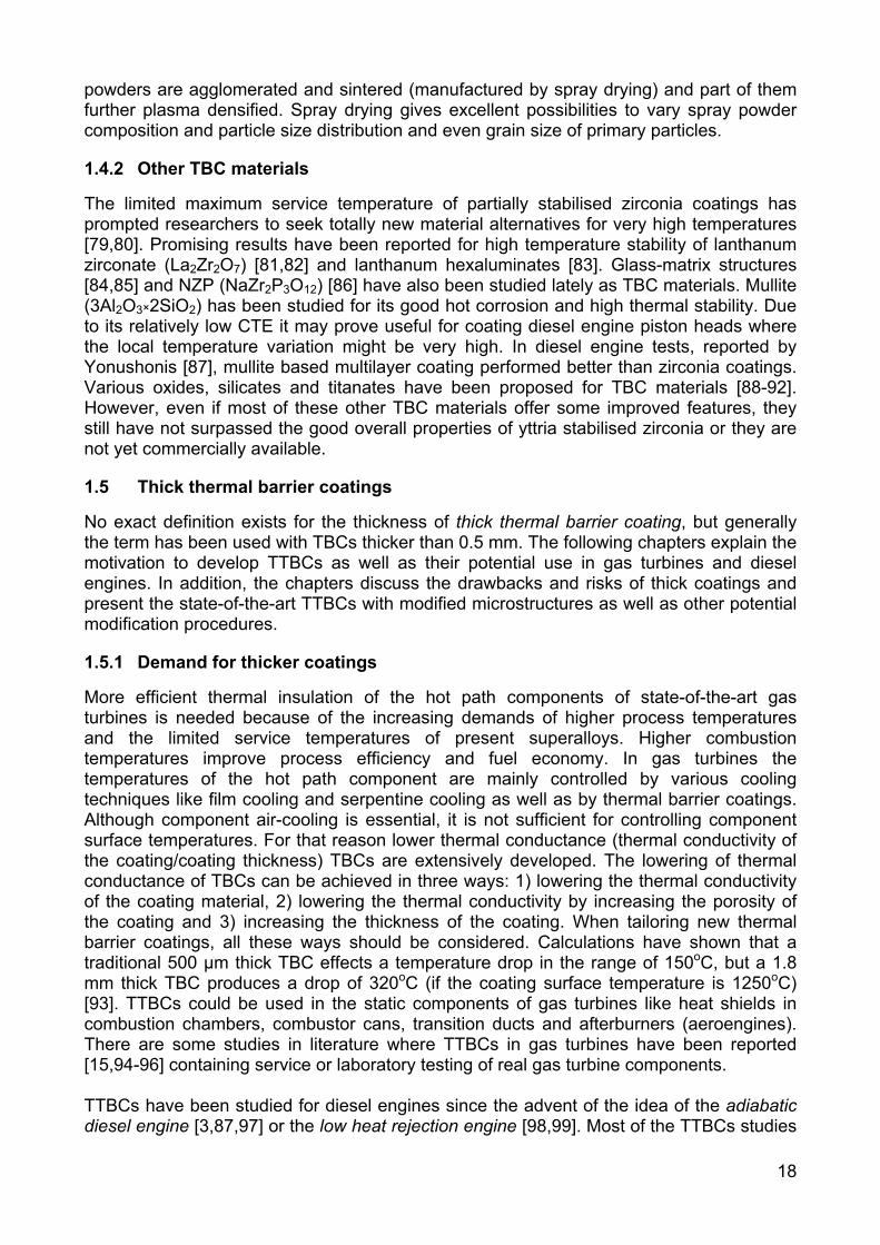
Thermal barrier coatings (TBCs) have been used since the 60’s in thermal protection of gas turbine hot section components [1,2]. From the early 1980s, many investigators have applied TBCs to the combustion chambers of diesel engines as well to lower heat losses. [3-6]. As a TBC material, most investigators have used zirconia (ZrO2), partially stabilised by magnesia (MgO), calcia (CaO) or yttria (Y2O3), because of its low thermal conductivity, high temperature stability and relatively high coefficient of thermal expansion (CTE) compared to other ceramic materials. Traditional TBCs have been manufactured by atmospheric plasma spraying (APS) using the partially stabilised zirconia in powder form as the raw material for coating. Surface temperature of metallic components working at high temperatures can be reduced by 100-300oC by using TBCs [7,8]. This temperature drop is significant considering the mechanical properties of the structural materials, such as cobalt or nickel based superalloys. In practice TBCs can extend the maintenance interval and component lifetime. On the other hand TBCs make it possible to improve the process efficiency by increasing the combustion temperature. Continually increasing process temperatures set high requirements for TBC development too. Fig. 1 illustrates the effect of TBC on the temperature gradient of a diesel engine piston head.
Tem
pera
ture
coolingsystem
basematerial
bondcoat TBC combustion
chamber
Fig. 1. Schematic illustration of the effect of TBC on temperature gradient of a diesel engine piston head.
1.1 Applications of thermal barrier coatings
1.1.1 Gas turbine
In the last decades the efficiency of gas turbines has improved greatly. State-of-the-art gas turbines are reaching 40 % efficiency [9] and combined cycle efficiencies as high as 60% are now achievable [10]. This improved efficiency has been made possible by the increase of combustion temperatures mainly achieved through using various cooling techniques, TBCs and modern superalloy materials. Turbine inlet temperatures in stationary gas turbines are normally over 1100oC, in modern turbines close to 1500oC [9,11,12] and in aeroengines even higher [9,13]. TBCs are widely used in gas turbine hot section components such as burners, transition ducts, shrouds, blades and vanes. The use of TBCs in gas turbine components is well documented in the literature [9,10,14-17].
14
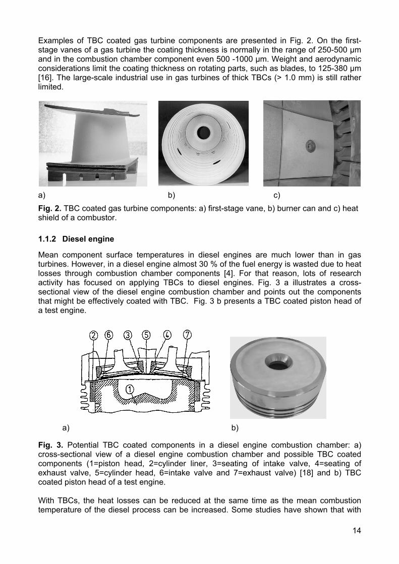
Examples of TBC coated gas turbine components are presented in Fig. 2. On the first-stage vanes of a gas turbine the coating thickness is normally in the range of 250-500 µm and in the combustion chamber component even 500 -1000 µm. Weight and aerodynamic considerations limit the coating thickness on rotating parts, such as blades, to 125-380 µm [16]. The large-scale industrial use in gas turbines of thick TBCs (> 1.0 mm) is still rather limited.
a) b) c) Fig. 2. TBC coated gas turbine components: a) first-stage vane, b) burner can and c) heat shield of a combustor.
1.1.2 Diesel engine
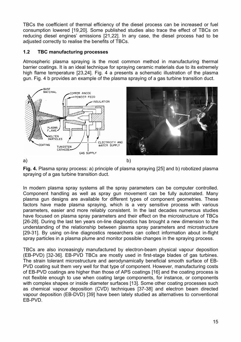
Mean component surface temperatures in diesel engines are much lower than in gas turbines. However, in a diesel engine almost 30 % of the fuel energy is wasted due to heat losses through combustion chamber components [4]. For that reason, lots of research activity has focused on applying TBCs to diesel engines. Fig. 3 a illustrates a cross-sectional view of the diesel engine combustion chamber and points out the components that might be effectively coated with TBC. Fig. 3 b presents a TBC coated piston head of a test engine.
a) b)
Fig. 3. Potential TBC coated components in a diesel engine combustion chamber: a) cross-sectional view of a diesel engine combustion chamber and possible TBC coated components (1=piston head, 2=cylinder liner, 3=seating of intake valve, 4=seating of exhaust valve, 5=cylinder head, 6=intake valve and 7=exhaust valve) [18] and b) TBC coated piston head of a test engine. With TBCs, the heat losses can be reduced at the same time as the mean combustion temperature of the diesel process can be increased. Some studies have shown that with
15
TBCs the coefficient of thermal efficiency of the diesel process can be increased or fuel consumption lowered [19,20]. Some published studies also trace the effect of TBCs on reducing diesel engines’ emissions [21,22]. In any case, the diesel process had to be adjusted correctly to realise the benefits of TBCs.
1.2 TBC manufacturing processes
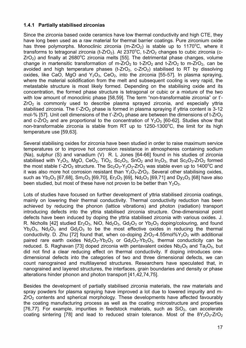
Atmospheric plasma spraying is the most common method in manufacturing thermal barrier coatings. It is an ideal technique for spraying ceramic materials due to its extremely high flame temperature [23,24]. Fig. 4 a presents a schematic illustration of the plasma gun. Fig. 4 b provides an example of the plasma spraying of a gas turbine transition duct.
a) b) Fig. 4. Plasma spray process: a) principle of plasma spraying [25] and b) robotized plasma spraying of a gas turbine transition duct. In modern plasma spray systems all the spray parameters can be computer controlled. Component handling as well as spray gun movement can be fully automated. Many plasma gun designs are available for different types of component geometries. These factors have made plasma spraying, which is a very sensitive process with various parameters, easier and more reliably consistent. In the last decades numerous studies have focused on plasma spray parameters and their effect on the microstructure of TBCs [26-28]. During the last ten years on-line diagnostics has brought a new dimension to the understanding of the relationship between plasma spray parameters and microstructure [29-31]. By using on-line diagnostics researchers can collect information about in-flight spray particles in a plasma plume and monitor possible changes in the spraying process. TBCs are also increasingly manufactured by electron-beam physical vapour deposition (EB-PVD) [32-36]. EB-PVD TBCs are mostly used in first-stage blades of gas turbines. The strain tolerant microstructure and aerodynamically beneficial smooth surface of EB-PVD coating suit them very well for that type of component. However, manufacturing costs of EB-PVD coatings are higher than those of APS coatings [16] and the coating process is not flexible enough to use when coating large components, for instance, or components with complex shapes or inside diameter surfaces [13]. Some other coating processes such as chemical vapour deposition (CVD) techniques [37-38] and electron beam directed vapour deposition (EB-DVD) [39] have been lately studied as alternatives to conventional EB-PVD.

16
1.3 TBC structure and design
The thermal barrier coating system consists of a thermal insulation layer and bond coating. The typical thickness of a TBC layer is 150-500 µm and 150-250 µm for bond coating. Schematic illustrations of plasma sprayed and EB-PVD TBC structures are presented in Fig. 5. The properties required from a TBC layer are low thermal conductivity, high stain tolerance, long-term stability at high temperatures, good erosion and hot corrosion resistance. The lamellar and porous microstructure of plasma sprayed coating is advantageous if considering low thermal conductivity and strain tolerance, but erosion and hot corrosion properties can be moderate. APS TBC is mechanically bonded to the bond coat, whereas chemical bonding is formed in EB-PVD coating (due to thermally grown oxide (TGO)). The columnar microstructure of EB-PVD coating is extremely strain tolerant [9,32,40], but its thermal conductivity is higher than that of plasma sprayed coating [9,32,41,42].
superalloy
bond coat
superalloy
bond coat + TGO
a) b) Fig. 5. Schematic illustrations of TBC structures: a) plasma sprayed and b) EB-PVD coating. The bond coat is an essential part of the TBC system. It improves the oxidation resistance of the superalloy substrate material and enhances adhesion of TBC. Bond coatings are typically thermally sprayed MCrAlYXs (M = Ni, Co, NiCo, CoNi and X = refractory metal) or diffusion aluminides. MCrAlYXs are manufactured by vacuum plasma spraying (VPS) or low pressure plasma spraying (LPPS) [9,43,44], high velocity oxy-fuel spraying (HVOF) [9, 45-47], EB-PVD [48] and lately also by electrodeposition [9,49]. Diffusion alumide bond coats can be produced by pack cementation based methods [9,43,50-52], the slurry process [52,53] and CVD methods [54]. All bond coating processes include specific heat treatment in order to obtain proper microstructure and phase composition as well as good adhesion to substrate.
1.4 TBC materials
As stated earlier, the TBC material should have low thermal conductivity k(T) and a CTE close to those of the metallic bond coatings and substrates. It should also have long-term phase stability at whole service temperature range and adequate corrosion resistance against impurities present in the process (such as Na, S, V). TBC material should have a low sintering tendency to maintain the strain tolerant microstructure. Sufficient mechanical properties are also needed (bond strength, erosion resistance). Various materials, mostly oxide ceramics, have been studied as TBC candidates. Partially stabilised zirconia is the most used TBC material, and 8Y2O3-ZrO2 has been the industrial standard composition for years. The following two chapters present the partially stabilised zirconia structures as well as the other TBC material alternatives.
17
1.4.1 Partially stabilised zirconias
Since the zirconia based oxide ceramics have low thermal conductivity and high CTE, they have long been used as a raw material for thermal barrier coatings. Pure zirconium oxide has three polymorphs. Monoclinic zirconia (m-ZrO2) is stable up to 1170oC, where it transforms to tetragonal zirconia (t-ZrO2). At 2370oC, t-ZrO2 changes to cubic zirconia (c-ZrO2) and finally at 2680oC zirconia melts [55]. The detrimental phase changes, volume change in martensitic transformation of m-ZrO2 to t-ZrO2 and t-ZrO2 to m-ZrO2, can be avoided and high temperature phases (t-ZrO2, c-ZrO2) stabilised to RT by dissolving oxides, like CaO, MgO and Y2O3, CeO2, into the zirconia [55-57]. In plasma spraying, where the material solidification from the melt and subsequent cooling is very rapid, the metastable structure is most likely formed. Depending on the stabilising oxide and its concentration, the formed phase structure is tetragonal or cubic or a mixture of the two with low amount of monoclinic phase [58,59]. The term “non-transformable zirconia” or t’-ZrO2 is commonly used to describe plasma sprayed zirconia, and especially yttria stabilised zirconia. The t’-ZrO2 phase is formed in plasma spraying if yttria content is 3-12 mol-% [57]. Unit cell dimensions of the t’-ZrO2 phase are between the dimensions of t-ZrO2 and c-ZrO2 and are proportional to the concentration of Y2O3 [60-62]. Studies show that non-transformable zirconia is stable from RT up to 1250-1300oC, the limit for its high temperature use [59,63]. Several stabilising oxides for zirconia have been studied in order to raise maximum service temperatures or to improve hot corrosion resistance in atmospheres containing sodium (Na), sulphur (S) and vanadium (V) R. L Jones [64-66] found in his studies of zirconia stabilised with Y2O3, MgO, CeO2, TiO2, Sc2O3, SnO2 and In2O3, that Sc2O3-ZrO2 formed the most stable t’-ZrO2 structure. The Sc2O3-Y2O3-ZrO2 was stable even up to 1400oC and it was also more hot corrosion resistant than Y2O3-ZrO2. Several other stabilising oxides, such as Yb2O3 [67,68], Sm2O3 [69,70], Er2O3 [69], Nd2O3 [69,71] and Dy2O3 [68] have also been studied, but most of these have not proven to be better than Y2O3. Lots of studies have focused on further development of yttria stabilised zirconia coatings, mainly on lowering their thermal conductivity. Thermal conductivity reduction has been achieved by reducing the phonon (lattice vibrations) and photon (radiation) transport introducing defects into the yttria stabilised zirconia structure. One-dimensional point defects have been induced by doping the yttria stabilised zirconia with various oxides. J. R. Nicholls [42] studied Er2O3, NiO, Nd2O3, Gd2O3 or Yb2O3 doping/colouring, and found Yb2O3, Nd2O3 and Gd2O3 to be the most effective oxides in reducing the thermal conductivity. D. Zhu [72] found that, when co-doping ZrO2-4.55mol%Y2O3 with additional paired rare earth oxides Nd2O3-Yb2O3 or Gd2O3-Yb2O3, thermal conducticity can be reduced. S. Raghavan [73] doped zirconia with pentavalent oxides Nb2O5 and Ta2O5, but did not find a clear reducing effect on thermal conductivity. If doping introduces one-dimensional defects into the categories of two and three dimensional defects, we can count nanograined and multilayered structures. Researchers have speculated that, in nanograined and layered structures, the interfaces, grain boundaries and density or phase alterations hinder phonon and photon transport [41,42,74,75]. Besides the development of partially stabilised zirconia materials, the raw materials and spray powders for plasma spraying have improved a lot due to lowered impurity and m-ZrO2 contents and spherical morphology. These developments have affected favourably the coating manufacturing process as well as the coating microstructure and properties [76,77]. For example, impurities in feedstock materials, such as SiO2, can accelerate coating sintering [78] and lead to reduced strain tolerance. Most of the 8Y2O3-ZrO2
18
powders are agglomerated and sintered (manufactured by spray drying) and part of them further plasma densified. Spray drying gives excellent possibilities to vary spray powder composition and particle size distribution and even grain size of primary particles.
1.4.2 Other TBC materials
The limited maximum service temperature of partially stabilised zirconia coatings has prompted researchers to seek totally new material alternatives for very high temperatures [79,80]. Promising results have been reported for high temperature stability of lanthanum zirconate (La2Zr2O7) [81,82] and lanthanum hexaluminates [83]. Glass-matrix structures [84,85] and NZP (NaZr2P3O12) [86] have also been studied lately as TBC materials. Mullite (3Al2O3×2SiO2) has been studied for its good hot corrosion and high thermal stability. Due to its relatively low CTE it may prove useful for coating diesel engine piston heads where the local temperature variation might be very high. In diesel engine tests, reported by Yonushonis [87], mullite based multilayer coating performed better than zirconia coatings. Various oxides, silicates and titanates have been proposed for TBC materials [88-92]. However, even if most of these other TBC materials offer some improved features, they still have not surpassed the good overall properties of yttria stabilised zirconia or they are not yet commercially available.
1.5 Thick thermal barrier coatings
No exact definition exists for the thickness of thick thermal barrier coating, but generally the term has been used with TBCs thicker than 0.5 mm. The following chapters explain the motivation to develop TTBCs as well as their potential use in gas turbines and diesel engines. In addition, the chapters discuss the drawbacks and risks of thick coatings and present the state-of-the-art TTBCs with modified microstructures as well as other potential modification procedures.
1.5.1 Demand for thicker coatings
More efficient thermal insulation of the hot path components of state-of-the-art gas turbines is needed because of the increasing demands of higher process temperatures and the limited service temperatures of present superalloys. Higher combustion temperatures improve process efficiency and fuel economy. In gas turbines the temperatures of the hot path component are mainly controlled by various cooling techniques like film cooling and serpentine cooling as well as by thermal barrier coatings. Although component air-cooling is essential, it is not sufficient for controlling component surface temperatures. For that reason lower thermal conductance (thermal conductivity of the coating/coating thickness) TBCs are extensively developed. The lowering of thermal conductance of TBCs can be achieved in three ways: 1) lowering the thermal conductivity of the coating material, 2) lowering the thermal conductivity by increasing the porosity of the coating and 3) increasing the thickness of the coating. When tailoring new thermal barrier coatings, all these ways should be considered. Calculations have shown that a traditional 500 µm thick TBC effects a temperature drop in the range of 150oC, but a 1.8 mm thick TBC produces a drop of 320oC (if the coating surface temperature is 1250oC) [93]. TTBCs could be used in the static components of gas turbines like heat shields in combustion chambers, combustor cans, transition ducts and afterburners (aeroengines). There are some studies in literature where TTBCs in gas turbines have been reported [15,94-96] containing service or laboratory testing of real gas turbine components. TTBCs have been studied for diesel engines since the advent of the idea of the adiabatic diesel engine [3,87,97] or the low heat rejection engine [98,99]. Most of the TTBCs studies
19
for diesel engines have been focused on small and medium sized diesel engines, used in vehicles and ships. TTBCs could potentially be utilized in high-powered diesel engines (even up to 80 MW) designed mainly for marine and power station use. The basic goal of applying TTBCs in diesel engines has been to minimize the heat losses through the combustion chamber components. Since 30 % of the heat losses of combustion chamber wall structures flow through the piston [4] it has been the component most often targeted for applying TTBCs. Piston head coatings of up to 3.5 mm thick have been studied in order to minimize the heat losses and to reach the targeted temperature drop through the coating [100]. If the heat losses of a diesel engine were lowered, the extra heat, available for the exhaust gases, could be converted in a flue gas boiler to heat or electricity or in a turbocharger to mechanical energy. In such ways the total process efficiency could be improved. Several studies have been published documenting the testing of TTBC coated diesel engine components [87,101-104].
1.5.2 Drawbacks of TTBCs
Several studies [96,105,106] have shown that, as the thickness of plasma sprayed TBCs increases, their reliability deteriorates, especially when exposed to thermal cycling. So only increasing the coating thickness, without modifying the coating microstructure, will not produce strain tolerant thick thermal barrier coatings. With thicker coatings the problems with residual stresses, originating in the coating manufacturing, are emphasized. When the coating thickness is increased by introducing more spray passes, the substrate and coating temperature rises step by step unless adequate cooling is used. This temperature increase reduces the cooling rate of individual splats and leads to better contact of lamellae and decreased number of vertical microcracks in lamellae. These are the mechanisms through which the tensile (quenching) stresses impact the coating. After the spraying, when the component cools down, compressive (thermal) stress is induced to TBC (CTETBC < CTESUBSTRATE). The final residual stress state of the coating is a sum of all the stress components, in this case mainly the quenching and thermal stresses. The formation of residual stresses (or strains) in plasma sprayed coatings and TBCs has been widely studied [107-111]. It has been reported that residual stresses in plasma sprayed TBCs can be tensile or compressive and can be affected by controlling the substrate temperature during spraying [112-114]. In the same studies it was also reported that the stress state change in high temperature exposure is towards compression. Considering the combined effect of residual stresses and the stresses caused by thermal cycling loads on TBCs, the residual stresses, as low as possible, should be beneficial. The bond strength or the intrinsic cohesion of the coating is also lowered in thicker coatings [106]. The following chapter will discuss how the stresses can be affected in plasma sprayed TTBCs. All these drawbacks of traditionally prepared TTBCs, residual stresses, low bond strength and low strain tolerance, combine to lower the reliability of the coating. With increased coating thickness the temperature drop through the coating increases at service temperatures and at the same time the dimensional mismatch of the coating surface and bond coat interface becomes higher, due to low strain tolerance. This dynamic induces more stresses into the structure and increases total strain energy available for crack initiation. Typically with TTBCs the crack is initiated near the bond coat interface leading to macroscopic coating delamination. In practice the coating failure mechanism is not so simple: varying thermal loads due to thermal cycling, thermal shocks and local hot spots make the situation even more difficult.
20
Several other risks have to be taken into account when considering the use of TTBCs in modern gas turbines, where the turbine inlet temperatures are extremely high (1350-1500oC). The use of thicker coatings generally leads to higher coating surface temperatures that can be detrimental in many ways, if certain limit are exceeded: 1) The phase structure of yttria stabilised zirconia 8Y2O3-ZrO2 is not stable above the 1250oC and can destabilise quite rapidly at 1400oC [59,63], 2) sintering of the plasma sprayed zirconia can take place already at 1200oC [115,116], that increase the coating stiffness and reduce the strain tolerance of the coating, 3) the creep rate of the coating increases with higher temperatures, which still can weaken the strain tolerance of the coating [116,117]. The literature also contains accounts of some diesel engine experiments with TTBC coated piston heads in which the coating lifetime has been poor [87,101-103,118]. In the piston head surface, the local stresses on the coating can be very high in hot spots where the fuel is injected. Even if the mean surface temperatures of the TBC in diesel engine remains at lower level than in gas turbines, the surface temperature swing during the one engine cycle can be 240-350oC higher [19,119]. Pressure variations in the combustion chamber and the high velocity of the piston exacerbate the severe high cycle fatigue loading on the piston head surface.
1.5.3 Microstructural modifications of TBCs
Modification of the microstructure of plasma sprayed TTBCs as well as traditional thin TBC has been widely studied as a means of improving a variety of coating properties such as strain tolerance, thermal conductivity, hot corrosion and erosion resistance. In this work the modification processes have been divided into three classes. Class A includes processes where the coating structure is influenced during manufacturing, through processes such as spray parameter controlling and special cooling techniques. Class B contains modifications in which the coating structure is not the typical double layer, but a graded or multilayered structure. Class C includes different types of post treatments such as sealing, densification and surface remelting processes. Each of these classes is presented in more detail in the following paragraphs. A) In the case of TTBCs the structural modifications have been mainly concentrated on lowering the Young's modulus (E) and residual strains/stresses of the coating for obtaining better strain tolerance [93,94,106,120]. This modification has been approached by introducing segmentation cracks [95,120] or a special microcrack network into the coating structure [121-123] or by increasing the coating porosity [93]. Vertical segmentation cracks can be obtained by using rather thick spray passes, short spray distance and particular substrate preheating [120]. A. S. Grot et al. [124] as early as 1981 studied the segmented 6Y2O3-ZrO2 structures where the vertical macrocracks went through the whole coating thickness. In burner rig type hot corrosion tests with 30.5 l/h SO2 gas, 20 ppm sea salt at 704oC and 899oC, they showed that some corrosives penetrated into the segmentation cracks. The overall performance of the segmented coatings in burner rig tests was good. D. Schwingel et al. [120] and P. Bengtsson [95] found in their studies that the lifetime of the segmentation cracked TTBC was significantly better compared to normal TTBC structure. At the same time the Young’s modulus of the coating was much reduced. Several studies [121-123] of atmosphere and temperature controlled spraying (ATCS) have been reported. In the ATCS technique cryogenic surface cooling is used during spraying in order to intensify the formation of microcracks in the lamellae. Microcracks are formed due to the increased cooling rate of the splats. By ATCS it was possible to improve coating strain tolerance and thermal cycling lifetime as well as
21
to reduce coating residual stresses [122,123]. H.-D. Steffens et al. [106] presented results for TTBCs of reduced residual stresses and improved thermal shock resistance when using various cooling techniques in plasma spraying. In plasma spraying it is possible to affect the TBC porosity to some degree. However, the normal porosity of TBCs is already at a rather high level (10-15 %) and further porosity increase by changing spray parameters could be difficult. Extremely high porosity values, up to 25 vol%, of TBCs have been obtained by spraying polymers together with zirconia [93]. Increasing the coating porosity decreases thermal conductivity and Young’s modulus is expected to decrease too. Some further drawbacks should be taken into account as well. Due to the increased number of cracks and pores the mechanical properties like adhesion and cohesion, erosion resistance and hot corrosion resistance of the modified TTBCs, presented in previous paragraph, might be slightly weakened. B) Many studies have focused on functionally graded materials (FGMs) in order to improve the properties of TTBCs. The gradient has often been constructed by mixing the starting material powders TBC and MCrAlY (bond coat) in various fractions. In many cases the focus has been on lowering the critical stresses in the structure caused by differences in the CTEs of the coating and substrate material [104,125-130]. But also other properties such as enhanced erosion resistance [130] and bond strength [128] as well as lowered oxygen transport in TBC [126] have been reported. However it should be remembered that the metal phase in graded structures have very large surface areas and for that reason are susceptible to oxidation at high temperatures. C) Lots of work has been done in modifying the properties of the TBCs by various post treatment processes. Post treatments, such as different sealing treatments and surface remelting and densification procedures, have been used mainly for improving the hot corrosion and erosion resistance of the coatings by closing the open pores on the coating surface. Most of these studies have focused on thin TBCs (< 1 mm). A. Ohmori et al. [131,132] studied sealing of TBCs by liquid manganese and manganese alloys (Mn-Cu, Mn-Sn, Mn-In). With the liquid metal impregnation it was possible to increase elastic modulus, microhardness and fracture toughness of the coatings. I. Zaplatynsky [133] studied the effect of laser glazing (CO2 laser) on the microstructure and properties of 8Y2O3-ZrO2 coatings. The lifetime of the laser-glazed coatings was extended four times in burner rig type hot corrosion tests, where 100 ppm of NaCl + 0.05 wt% S in fuel was used at Tmax=843oC. The result was explained by the reduced permeability of the coating surface. Laser glazing did not affect the coating behaviour in cyclic oxidation tests, even if there were vertical cracks in the coating. R. Sivakumar et al. [134] performed a comprehensive study of the CO2 laser melting of the plasma sprayed CaO, MgO and Y2O3 stabilised zirconia coatings. In the hot corrosion exposure to molten salt of 95Na2SO4-5NaCl at 950oC for 100 h, the laser-glazed zirconia coatings performed worse than the as-sprayed ones. The melt deposit penetrated into the vertical cracks, induced by laser glazing, and caused severe oxidation of the bond coat. H. L. Tsai et al. [135,136] studied sealing of 6-20 wt% yttria stabilised zirconia TBC coatings with CO2 laser. Coatings were exposed to thermal cycling/oxidation tests in which the coatings were kept at 1100±5oC for 1 hour and then cooled to ambient temperature in 10 minutes by pressurized air. They did not find any effect of laser glazing on the bond coat oxidation, but the lifetime in thermal cycling tests was increased by 2 -6 times, depending on the coating
22
composition. A. Petitbon et al. [137] studied surface melting and over-cladding of the Y2O3 and Y2O3/HfO2 stabilised zirconia coatings by CO2 laser. The cladding was made using Al2O3 powder. Laser treatments improved thermal cycling, Tmax 1200oC, dwell 5 min, Tmin 100oC, dwell 5 min, properties as well as friction and erosion resistance. Finally the Al2O3 cladded TBC coatings were proved to be superior in an “in-service” test, where adjacent flaps of the FALCON F16 fighter turbine were tested for 150 hours. K. A. Khor et al. [138] performed sealing experiments with Nd-YAG laser for 5CaO-ZrO2 coatings. Microhardnesses of properly melted surface areas were doubled if compared to as-sprayed coating. A. Zhou et al. [139,140] studied the hybrid spray process, combined plasma spraying and Nd-YAG laser, in manufacturing 8Y2O3-ZrO2 coatings. It was found that coating microhardness and wear resistance were increased. H. Kuribayashi et al. [141] studied densification of TBC coatings by the hot isostatic pressing (HIP) process. They found that mechanical properties of the coatings increased significantly, hardness from 5 GPa to 13,3 GPa, tensile strength from 5 MPa to 60 MPa. K. A. Khor et al. [142,143] studied HIPing of the 8Y2O3-ZrO2 and 5CaO-ZrO2 coatings. Coating porosity was reduced whereas thermal diffusivity and microhardness was increased. K. Moriya et al. [144,145] studied sealing of plasma sprayed coatings by the sol-gel process, where Al2O3 and SiO2 based precursors were impregnated into Al2O3 and 8Y2O3-ZrO2 coatings. Metal alkoxides, Al(OC3H7)3 and Si(OC2H5)4, together with water and HCl, were used as starting materials for Al2O3 and SiO2 based precursors. Adhesive strength of the coatings increased significantly due to the sealing process. Porosity of the coatings was also reduced. G. John et al. [146] made sealing experiments for 8Y2O3-ZrO2 coatings with alumina and silica based sol-gels. Potentiodynamic polarization tests in aqueous 3 wt% NaCl solution and gas permeability tests showed the reduction of coating open porosity as a function of impregnation time. Coating adhesion was also improved. I. Berezin et al. [147] used a silica based precursor (pre-hydrolyzed ethyl silicate, Si(OC2H5)) in sealing 8Y2O3-ZrO2 coatings. Microhardness of the sealed coatings was increased even if it was estimated that only 1/10 of the open porosity could be sealed with one infiltration cycle. J. Kathikeyan at al. [148] made sealing experiments for free standing 8Y2O3-ZrO2 coatings with aqueous based aluminium hydroxide precursor. Mercury porosimetry showed the porosity reduction and the change of the pore size distribution. T. Troczynski et al. [149,150] studied physico-chemical sealing treatments for yttria stabilised ZrO2 coatings with sol-gel impregnation and laser glazing (CO2 laser). They also performed laser glazing for sol-gel sealed specimens. In thermal shock tests at Tmax=1270oC and air cooling, the sol-gel sealed coatings lasted longer than as-sprayed coatings, but the laser-glazed as well as the sol-gel sealed + laser-glazed coatings performed best. Borisova et al. [151] sealed flame sprayed zirconia coatings by phosphate based sealants. In sealing experiments they used aluminium-chromium phosphate and orthophosphoric acid (H3PO4). It was found that the sealing treatment strengthened the coating structure.
23
1.6 Aims of the study
The aim of the study was to improve the properties of thick thermal barrier coatings by modifying their microstructures by several post treatments, mainly concentrating on phosphate sealing and laser glazing. Phosphate sealing was mainly performed in order to densify the surface layer of the porous plasma sprayed TTBC. The purpose of the surface densification processes was to increase erosion and hot corrosion resistance of TTBCs without deteriorating the other important coating properties such as thermal conductivity and strain tolerance. The coating microstructures were modified also by laser glazing to densify the surface of the coating and to introduce a special crack structure into the coating. In laser-glazed coatings, in addition to erosion and hot corrosion resistance, also the strain tolerance was expected to improve if beneficial vertical macrocrack networks could be created. The study started with the optimisation of each modification procedure and continued with coating microstructural characterisation. Then the mechanical, wear and thermal properties of the coatings were determined, and finally their high temperature behaviour was tested in hot corrosion and thermal cycling experiments. At a rather early stage of the study the phosphate sealing and laser glazing seemed to be the most promising ways to affect coating microstructures. For that reason this thesis mostly focuses on the results of these two modification processes and only briefly discusses the other processes, such as sol-gel sealing and dense overlay coatings prepared by detonation gun spraying.
24
2. EXPERIMENTAL PROCEDURES
This chapter introduces the materials, coatings and coating modification procedures studied in this work and describes the characterisation and testing methods used.
2.1 Studied materials and coating modification procedures
Coatings were produced by thermal spraying techniques. Ceramic TTBCs and their bond coatings were prepared mainly by APS. In some special cases HVOF and detonation gun spray processes were applied. All the coatings were sprayed using commercial feedstock powders. Most of the coating modification procedures were post-treatments which were made for as-sprayed coatings.
2.1.1 Reference coatings and substrate materials
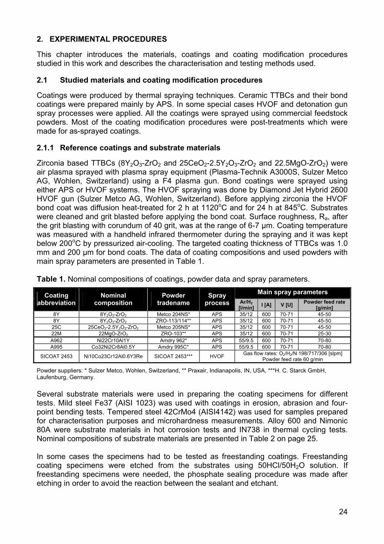
Zirconia based TTBCs (8Y2O3-ZrO2 and 25CeO2-2.5Y2O3-ZrO2 and 22.5MgO-ZrO2) were air plasma sprayed with plasma spray equipment (Plasma-Technik A3000S, Sulzer Metco AG, Wohlen, Switzerland) using a F4 plasma gun. Bond coatings were sprayed using either APS or HVOF systems. The HVOF spraying was done by Diamond Jet Hybrid 2600 HVOF gun (Sulzer Metco AG, Wohlen, Switzerland). Before applying zirconia the HVOF bond coat was diffusion heat-treated for 2 h at 1120oC and for 24 h at 845oC. Substrates were cleaned and grit blasted before applying the bond coat. Surface roughness, Ra, after the grit blasting with corundum of 40 grit, was at the range of 6-7 µm. Coating temperature was measured with a handheld infrared thermometer during the spraying and it was kept below 200oC by pressurized air-cooling. The targeted coating thickness of TTBCs was 1.0 mm and 200 µm for bond coats. The data of coating compositions and used powders with main spray parameters are presented in Table 1. Table 1. Nominal compositions of coatings, powder data and spray parameters.
Main spray parameters Coating abbreviation
Nominal composition
Powder tradename
Spray process Ar/H2
[l/min] I [A] V [U] Powder feed rate [g/min]
8Y 8Y2O3-ZrO2 Metco 204NS* APS 35/12 600 70-71 45-50 8Y 8Y2O3-ZrO2 ZRO-113/114** APS 35/12 600 70-71 45-50
25C 25CeO2-2.5Y2O3-ZrO2 Metco 205NS* APS 35/12 600 70-71 45-50 22M 22MgO-ZrO2 ZRO-103** APS 35/12 600 70-71 25-30 A962 Ni22Cr10Al1Y Amdry 962* APS 55/9.5 600 70-71 70-80 A995 Co32Ni2Cr8Al0.5Y Amdry 995C* APS 55/9.5 600 70-71 70-80
SICOAT 2453 Ni10Co23Cr12Al0.6Y3Re SICOAT 2453*** HVOF Gas flow rates: O2/H2/N 198/717/306 [slpm] Powder feed rate 60 g/min
Powder suppliers: * Sulzer Metco, Wohlen, Switzerland, ** Praxair, Indianapolis, IN, USA, ***H. C. Starck GmbH, Laufenburg, Germany. Several substrate materials were used in preparing the coating specimens for different tests. Mild steel Fe37 (AISI 1023) was used with coatings in erosion, abrasion and four-point bending tests. Tempered steel 42CrMo4 (AISI4142) was used for samples prepared for characterisation purposes and microhardness measurements. Alloy 600 and Nimonic 80A were substrate materials in hot corrosion tests and IN738 in thermal cycling tests. Nominal compositions of substrate materials are presented in Table 2 on page 25. In some cases the specimens had to be tested as freestanding coatings. Freestanding coating specimens were etched from the substrates using 50HCl/50H2O solution. If freestanding specimens were needed, the phosphate sealing procedure was made after etching in order to avoid the reaction between the sealant and etchant.

25
Table 2. Nominal compositions of substrate materials.
C Si Mn P S Cr Mo W Ni Fe Co B Cu Zr Ta Al Ti Fe37 <
0.18 0.15-0-50
< 1.00
< 0.045
< 0.045
< 0.25
< 0.10 - <
0.30 bal - - < 0.30 - - - -
42CrMo4 0.38-0.45
0.15-0.40
0.60-0.90
< 0.035
< 0.035
0.90-1.20
0.15-0.25 - - bal - - - - - - -
Alloy 600 - 0.5 1.0 - - 16.0 - - bal 8.0 - - 0.5 - - - - Nimonic 80A
< 0.10 < 1.0 < 1.0 - 0.015 18.0-
21.0 - - bal < 3.0
< 2.0
< 0.008
< 0.2
< 0.15 - 1.0-
1.8 1.8-2.7
IN738 0.17 - - - - 16.0 1.75 2.6 bal - 8.5 - - - 1.75 3.4 3.4
2.1.2 Phosphate based sealing procedures
8Y2O3-ZrO2 and 25CeO2-2.5Y2O3-ZrO2 coatings were sealed with Al(OH)3-(85%)H3PO4 solution diluted with 20 wt% of deionised water. The ratio of Al(OH)3:(85%)H3PO4 was 1:4.2 by weight which corresponds to a P/Al molar ratio of about 3. The solution was mixed and slightly heated with a magnetic stirrer until it became clear. 22MgO-ZrO2 coating was sealed with orthophosphoric acid (85%) H3PO4. Abbreviations used in this thesis are AP for aluminium phosphate sealing and OPA for orthophosphoric acid sealing. Stages in phosphate sealing process are presented in Fig. 6.
spreading the sealant
a)
sealant infiltration
b)
heat treatment (300 C,4h)o
c) d)
removal of extra sealant by grinding
Fig. 6. Stages in phosphate sealing treatment.
Sealant was spread onto the coating surface, and it instantly started to infiltrate into the coating cracks and pores. After that the specimens were placed in a furnace for heat treatment. The heat treatment was performed at 300oC for 4 hours. When removed from the furnace, the specimen was allowed to cool down to the room temperature. In the case of aluminium phosphate the extra sealant at the coating surface formed a porous “cake” that was removed by grinding. It was possible to remove the residues of the orthophosphoric acid sealant by wiping with a paper towel.

26
2.1.3 Laser glazing procedure
Coatings were laser-glazed using a 4 kW continuous wave fibre coupled HAAS HL4006D lamp-pumped Nd-YAG laser (HAAS-laser GmbH, Schramberg, Germany). The width of the laser beam was 10 mm at the focused area, which was at the distance of 80 mm from the mirror. Tracks, 10 mm wide, were processed with 2 mm overlapping if wider surfaces were needed. Schematic illustration of the laser glazing process and the surface of the laser-glazed 8Y2O3-ZrO2 coating are presented in Fig. 7.
Laser source
beam
a) b)
Fig. 7. Schematic illustration of the laser glazing process and the surface of the laser-glazed 8Y2O3-ZrO2 coating. Laser glazing parameters were optimised by comparing coating microstructures with different specific laser energy densities using continuous and pulsed laser beams. In the optimisation stage the predetermined melting depth of the coating surface was reached, without causing coating spallation. Also formation of too long vertical cracks, which pass through the thickness of the coating, was avoided. The optimised laser glazing parameters for studied coatings are presented in Table 3. Abbreviation LASER is used here for all laser-glazed coatings. Table 3. Laser glazing parameters for studied TTBCs.
8Y2O3-ZrO2 25CeO2-2.5Y2O3-ZrO2 22.5MgO-ZrO2 Laser power [kW] 3.5-4.0 3.0 3.5 Surface speed [mm/min] 3500-4500 4000 4500 Surface distance from the mirror [mm] 80 80 80 Laser beam specific energy density [J/mm2] 4.7-6.9 4.5 4.7
2.1.4 Other modification processes
This study mainly concentrated on phosphate sealed and laser-glazed coatings, but also other coating modification processes were studied to some degree. These results are mainly presented in included publications II and VI. The other modification processes are briefly described below:
2.1.4.1 Detonation gun sprayed dense top layers on TTBC Thin (50-200 µm) dense top coatings (8Y2O3-ZrO2, Cr2O3 and ZrSiO4) on TTBCs were sprayed with detonation gun (D-gun) spray equipment (Perun-P, Paton Electric Welding Institute, Kiev, Ukraine). With the D-gun it was possible to produce denser ceramic coatings than with the APS. This difference was mainly due to the higher particle
27
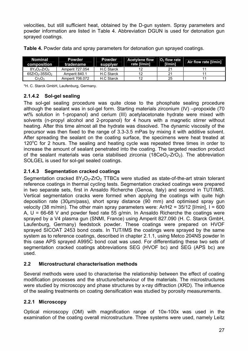
velocities, but still sufficient heat, obtained by the D-gun system. Spray parameters and powder information are listed in Table 4. Abbreviation DGUN is used for detonation gun sprayed coatings. Table 4. Powder data and spray parameters for detonation gun sprayed coatings.
*H. C. Starck GmbH, Laufenburg, Germany.
2.1.4.2 Sol-gel sealing The sol-gel sealing procedure was quite close to the phosphate sealing procedure although the sealant was in sol-gel form. Starting materials zirconium (IV) –propoxide (70 wt% solution in 1-propanol) and cerium (III) acetylacetonate hydrate were mixed with solvents (n-propyl alcohol and 2-propanol) for 4 hours with a magnetic stirrer without heating. After this time almost all the hydrate was dissolved. The dynamic viscosity of the precursor was then fixed to the range of 3.3-3.5 mPas by mixing it with additive solvent. After spreading the sealant on the coating surface, the specimens were heat treated at 120oC for 2 hours. The sealing and heating cycle was repeated three times in order to increase the amount of sealant penetrated into the coating. The targeted reaction product of the sealant materials was ceria stabilised zirconia (18CeO2-ZrO2). The abbreviation SOLGEL is used for sol-gel sealed coatings.
2.1.4.3 Segmentation cracked coatings Segmentation cracked 8Y2O3-ZrO2 TTBCs were studied as state-of-the-art strain tolerant reference coatings in thermal cycling tests. Segmentation cracked coatings were prepared in two separate sets, first in Ansaldo Richerche (Genoa, Italy) and second in TUT/IMS. Vertical segmentation cracks were formed when applying the coatings with quite high deposition rate (30µm/pass), short spray distance (90 mm) and optimised spray gun velocity (38 m/min). The other main spray parameters were: Ar/H2 = 35/12 [l/min], I = 600 A, U = 66-68 V and powder feed rate 55 g/min. In Ansaldo Richerche the coatings were sprayed by a V4 plasma gun (SNMI, France) using Amperit 827.090 (H. C. Starck GmbH, Laufenburg, Germany) feedstock powder. These coatings were prepared on HVOF sprayed SICOAT 2453 bond coats. In TUT/IMS the coatings were sprayed by the same system as to reference coatings, described in chapter 2.1.1, using Metco 204NS powder In this case APS sprayed A995C bond coat was used. For differentiating these two sets of segmentation cracked coatings abbreviations SEG (HVOF bc) and SEG (APS bc) are used.
2.2 Microstructural characterisation methods
Several methods were used to characterise the relationship between the effect of coating modification processes and the structure/behaviour of the materials. The microstructures were studied by microscopy and phase structures by x-ray diffraction (XRD). The influence of the sealing treatments on coating densification was studied by porosity measurements.
2.2.1 Microscopy
Optical microscopy (OM) with magnification range of 10x-100x was used in the examination of the coating overall microstructure. Three systems were used, namely Leitz
Nominal composition
Powder tradename
Powder supplyer
Acetylene flow rate [l/min]
O2 flow rate [l/min] Air flow rate [l/min]
8Y2O3-ZrO2 Amperit 727.054 H.C Starck 12 21 11 65ZrO2-35SiO2 Amperit 840.1 H.C Starck 12 21 11
Cr2O3 Amperit 706.072 H.C Starck 12 25 11
28
(Wetzlar, Germany), Versamet 3 (Union Co., Japan) and Carl Zeiss Axiophot (Germany). Scanning electron microscopy (SEM/ESEM, model Model XL-30, Philips, Eindhoven, Netherlands) was used with higher magnifications (100x-10 000x). Energy dispersive spectrometry (EDS, Model DX-4, EDAX International, New Jersey, USA) was used in elemental analysis in SEM studies. Transmission electron microscopy (TEM, Model JEM 2010, Jeol, Tokyo, Japan) was used at magnifications higher than 10 000x. In TEM studies selected area electron diffraction (SAED) was used to study the crystal structures. Cross-sectional samples for microscopy were cut by a precision cut-off machine and cold mounted in vacuum. Specimens were grinded by diamond grinding discs or by SiC papers. The final polishing was carried out by polishing cloths using diamond spray or diamond paste. In SEM investigations, where electrical conductivity of the sample is required, a thin layer of gold or carbon was sputtered on the specimens.
2.2.2 X-ray diffraction
X-ray diffraction was used in phase identification, quantitative phase analysis, texture determination and residual stress studies. The phase compositions of the coatings were identified with X-ray diffractometer (XRD, Siemens D500, Karlsruhe, Germany) using CuKα radiation with scan step of 0.02o and step time of 1.2 s. For more detailed quantitative phase analysis image plate X-ray diffractometer (XRD, Italstructures, Riva del Garda, Italy) was used. The image plate XRD system worked with CuKα radiation operating at 40kV and 30mA. The used exposure time was two hours and the analysed spectra were taken from 2θ range of 20-120o. The constant incident angle (Ω) between the x-ray source and the specimen surface was 15o. The image plate (x-ray sensitive film) diffraction pattern was scanned into a computer and the data was analysed using MAUD software (Material Analysis Using Diffraction, version 1.87 (Luca Lutterotti, University of Trento, Italy). In MAUD software the quantitative and texture analyses were carried out by the Rietveld method [152,153]. Residual stresses were measured using a XStress3000 stress analyser (Stresstech Oy, Vaajakoski, Finland). CrKα -radiation was used with 30 kV, 5.0 mA and 30 s exposure time. The traditional sin2ψ -method was carried out using specimen tilts of ψ=±0o, ±21.8o, ±31.7o and ±40o. In there the least squares method was used in fitting the measured points to a line (d(sind2θ) graph). Error of each measurement, presented as error bars in results, is an average error that expresses the goodness of fit of points to a line. The peak shifts of zirconia coatings were studied on (3 1 3) crystalline plane of t’–ZrO2 at 2θ position of 153o. Bulk material constants E = 205 GPa and υ = 0.23 for zirconia were used in stress calculations. Through thickness stress profiles were determined by repeating the measurements and layer removal steps. Layers were removed with careful grinding to avoid producing additional stresses or cracks.
2.2.3 Porosity and bulk density determination
Total porosity was evaluated from the coating cross-section by image analysis (IA) using optical microscope (Carl Zeiss Axiophot, Germany) and image acquisition and analysis software (QWin, Leica Microsystems, Switzerland). The results are presented as a mean value with standard deviation of five separate analyses from each type of coating. Open porosity was measured with mercury porosimetry (MP, models Pascal 140 and Porosimeter 2000, CE-instruments, Milan, Italy) over the pressure range of 0.1 kPa – 200 MPa. Bulk density of the coating was determined by the method of Archimedes [154].
29
2.3 Mechanical and wear property determination
The mechanical properties of the coatings were determined by microhardness measurements and by four-point bending tests (4PB). The 4PB tests were carried out in order to get data on the elastic behaviour of the coating. Wear properties of the coatings were evaluated by erosion and abrasion tests.
2.3.1 Microhardness
Coating microhardness, HV0.3, was determined by a microhardness tester (Shimadzu, Kioto, Japan) from the coating cross-sections. Results are presented as mean values of the five separate measurements.
2.3.2 Modulus of rupture in bending and bending modulus
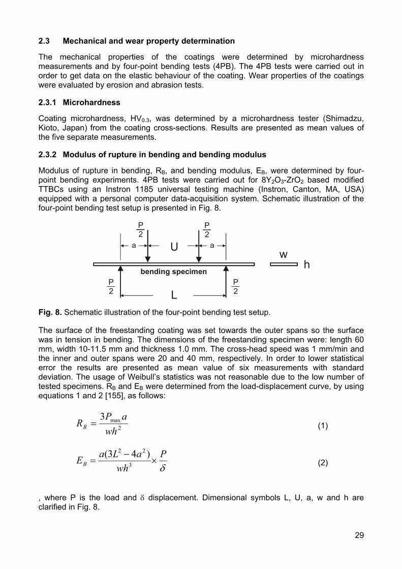
Modulus of rupture in bending, RB, and bending modulus, EB, were determined by four-point bending experiments. 4PB tests were carried out for 8Y2O3-ZrO2 based modified TTBCs using an Instron 1185 universal testing machine (Instron, Canton, MA, USA) equipped with a personal computer data-acquisition system. Schematic illustration of the four-point bending test setup is presented in Fig. 8.
LP2
P2
P2
P2
Uh
wa a
bending specimen
Fig. 8. Schematic illustration of the four-point bending test setup.
The surface of the freestanding coating was set towards the outer spans so the surface was in tension in bending. The dimensions of the freestanding specimen were: length 60 mm, width 10-11.5 mm and thickness 1.0 mm. The cross-head speed was 1 mm/min and the inner and outer spans were 20 and 40 mm, respectively. In order to lower statistical error the results are presented as mean value of six measurements with standard deviation. The usage of Weibull’s statistics was not reasonable due to the low number of tested specimens. RB and EB were determined from the load-displacement curve, by using equations 1 and 2 [155], as follows:
2max3wh
aPRB = (1)
δP
whaLaEB ×
−= 3
22 )43( (2)
, where P is the load and δ displacement. Dimensional symbols L, U, a, w and h are clarified in Fig. 8.
30
2.3.3 Erosion resistance
Erosion tests were performed with a centrifugal accelerator using SiO2 erosive, particle size of 0.05-0.1 mm. Specimens were tangentially attached to the centrifuge rim with fixed angles of 90o, 60o and 30o. Total amount of the erosive in one test was 1 kg and the average particle velocity was 80 m/s.
2.3.4 Abrasion resistance
Abrasion tests were carried out by the dry rubber wheel tester, a modified version of ASTM G65. Quartz sand, SiO2, was used as an abrasive with particle size of 0.1-0.6 mm. The load on each specimen was 13 N. Test duration was 1 h, which corresponds to the wear length of 5904 m.
2.4 Thermal property determination
Thermal expansion studies were used to study the high temperature stability of the modified coating structures. As low thermal conductivity is one of the most important features of TBCs, thermal diffusivity and specific heat measurements were carried out.
2.4.1 Thermal expansion
Thermal expansion studies and the determination of CTE were carried out by dilatometer (Adamel Lhomargy SAS, model DI-24, France) in air at a temperature range of 50-1300oC. The temperature ramping rate varied from 5oC/min to 10oC/min and dwell times at maximum temperature from 5 minutes to 5 hours.
2.4.2 Thermal diffusivity
Thermal diffusivity, α(T), measurements were carried out with laser flash apparatus Theta (Theta Industries Inc., Port Washington, NY, USA) in vacuum (< 0,01 Pa). Measurements were performed at 7 different temperatures in the temperature range of 100-1300oC. Measurements were repeated five times at each temperature for statistical reasons. Prior to evaluating the thermal diffusivity, in order to make the sample surfaces opaque, thin layers of colloidal graphite were painted on both the front and the rear faces. The measurement cycle was repeated 3 times for each coating in order to find out the effect of high temperature exposure of the previous measurement on α(T).
2.4.3 Specific heat
Specific heat, CP(T), measurements were performed by a Differential Scanning Calorimeter DSC 404 C (Netzsch-Gerätebau GmbH, Selb, Germany). The scanning rate was 15°C/min at the temperature range of 100°C up to 1250°C. Measurements were carried out in air and in argon atmospheres using either alumina or platinum crucibles. Weight of the free-standing coating specimen was approximately 80 mg. For each sample three consequent measurements cycles were performed in order to lower the statistical error of the measurement.
31
2.4.4 Thermal conductivity
Thermal conductivity, k(T), was calculated using equation 3. Thermal conductivity values were calculated in 50oC intervals at a temperature range of 150-1250oC. For these temperature points the thermal diffusivity data was interpolated from the original data.
BP TCTTk ρα ∗∗= )()()( (3) , where α(T) is thermal diffusivity, CP(T) specific heat at constant pressure and ρB bulk density,
2.5 Hot corrosion testing
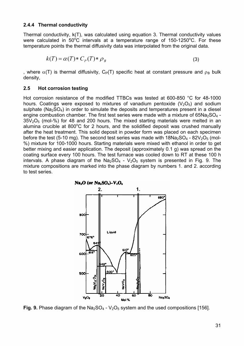
Hot corrosion resistance of the modified TTBCs was tested at 600-850 °C for 48-1000 hours. Coatings were exposed to mixtures of vanadium pentoxide (V2O5) and sodium sulphate (Na2SO4) in order to simulate the deposits and temperatures present in a diesel engine combustion chamber. The first test series were made with a mixture of 65Na2SO4 - 35V2O5 (mol-%) for 48 and 200 hours. The mixed starting materials were melted in an alumina crucible at 800oC for 2 hours, and the solidified deposit was crushed manually after the heat treatment. This solid deposit in powder form was placed on each specimen before the test (5-10 mg). The second test series was made with 18Na2SO4 - 82V2O5 (mol-%) mixture for 100-1000 hours. Starting materials were mixed with ethanol in order to get better mixing and easier application. The deposit (approximately 0.1 g) was spread on the coating surface every 100 hours. The test furnace was cooled down to RT at these 100 h intervals. A phase diagram of the Na2SO4 - V2O5 system is presented in Fig. 9. The mixture compositions are marked into the phase diagram by numbers 1. and 2. according to test series.
Fig. 9. Phase diagram of the Na2SO4 - V2O5 system and the used compositions [156].
32
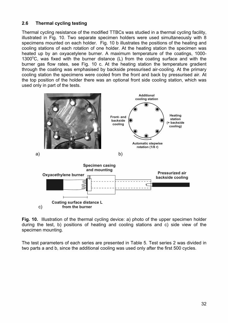
2.6 Thermal cycling testing
Thermal cycling resistance of the modified TTBCs was studied in a thermal cycling facility, illustrated in Fig. 10. Two separate specimen holders were used simultaneously with 8 specimens mounted on each holder. Fig. 10 b illustrates the positions of the heating and cooling stations of each rotation of one holder. At the heating station the specimen was heated up by an oxyacetylene burner. A maximum temperature of the coatings, 1000-1300oC, was fixed with the burner distance (L) from the coating surface and with the burner gas flow rates, see Fig. 10 c. At the heating station the temperature gradient through the coating was emphasised by backside pressurised air-cooling. At the primary cooling station the specimens were cooled from the front and back by pressurised air. At the top position of the holder there was an optional front side cooling station, which was used only in part of the tests.
Heating station
(+ backsidecooling)
Front- andbacksidecooling
Automatic stepwiserotation (1/8 r)
Additionalcooling station
a) b)
c)
Oxyacethylene burner Pressurized air backside cooling
Specimen casing and mounting
Coating surface distance L from the burner
Fig. 10. Illustration of the thermal cycling device: a) photo of the upper specimen holder during the test, b) positions of heating and cooling stations and c) side view of the specimen mounting. The test parameters of each series are presented in Table 5. Test series 2 was divided in two parts a and b, since the additional cooling was used only after the first 500 cycles.
33
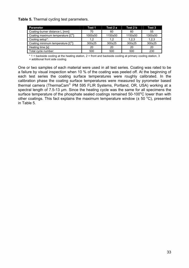
Table 5. Thermal cycling test parameters.
Parameter Test 1 Test 2 a Test 2 b Test 3 Coating-burner distance L [mm]: 70 60 60 55 Coating maximum temperature [Co]: 1000±50 1150±50 1150±50 1300±50 Cooling setup*: 1,2 1,2 1,2,3 1,2,3 Coating minimum temperature [Co]: 300±25 300±25 300±25 300±25 Heating time [s]: 20 20 20 20 Total cycle number: 500 500 500 230
* 1 = backside cooling at the heating station, 2 = front and backside cooling at primary cooling station, 3 = additional front side cooling.
One or two samples of each material were used in all test series. Coating was rated to be a failure by visual inspection when 10 % of the coating was peeled off. At the beginning of each test series the coating surface temperatures were roughly calibrated. In the calibration phase the coating surface temperatures were measured by pyrometer based thermal camera (ThermaCam PM 595 FLIR Systems, Portland, OR, USA) working at a spectral length of 7.5-13 µm. Since the heating cycle was the same for all specimens the surface temperature of the phosphate sealed coatings remained 50-100oC lower than with other coatings. This fact explains the maximum temperature window (± 50 oC), presented in Table 5.
34
3. RESULTS AND DISCUSSION
This chapter summarises and discusses the most important results of the included publications.
3.1 Microstructural characterisation
The microstructure of the coatings was studied by optical microscopy, porosity measurements, SEM+EDS, TEM and XRD to better understand the effect of phosphate sealing and laser glazing on surface densification [Publications I-III]. This chapter presents the characteristic microstructures and phase structures of the modified coatings.
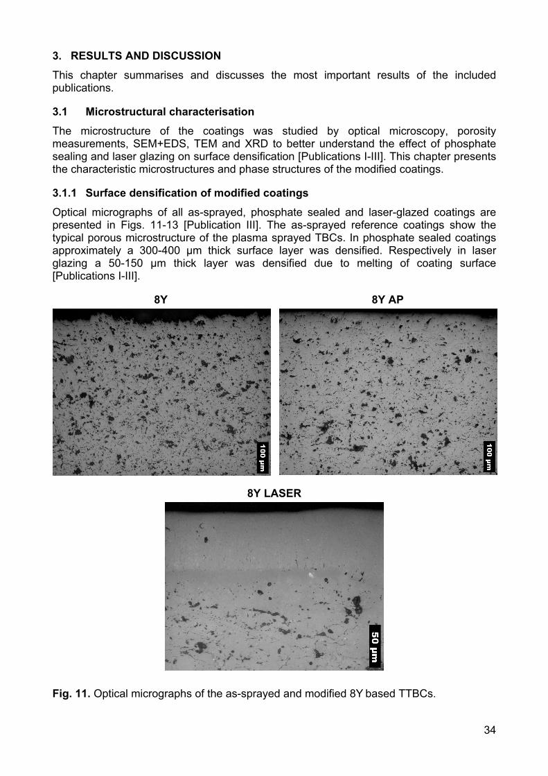
3.1.1 Surface densification of modified coatings
Optical micrographs of all as-sprayed, phosphate sealed and laser-glazed coatings are presented in Figs. 11-13 [Publication III]. The as-sprayed reference coatings show the typical porous microstructure of the plasma sprayed TBCs. In phosphate sealed coatings approximately a 300-400 µm thick surface layer was densified. Respectively in laser glazing a 50-150 µm thick layer was densified due to melting of coating surface [Publications I-III].
8Y 8Y AP
8Y LASER
Fig. 11. Optical micrographs of the as-sprayed and modified 8Y based TTBCs.
35
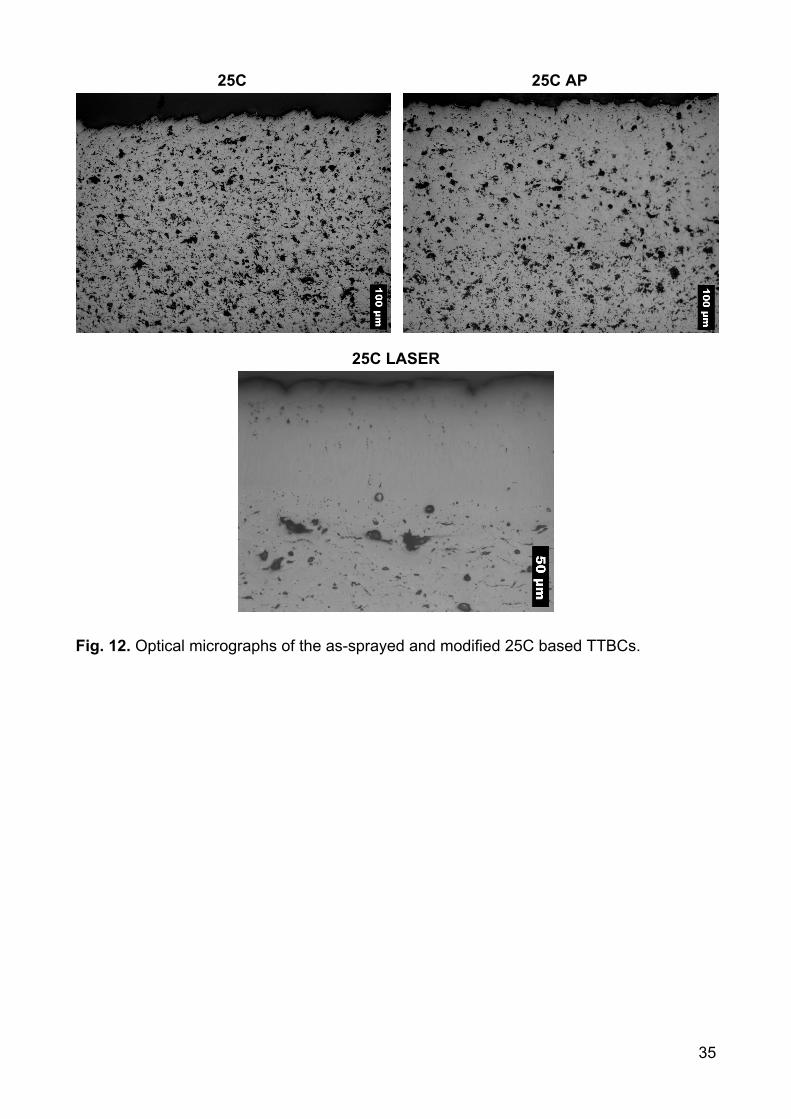
25C 25C AP
25C LASER
Fig. 12. Optical micrographs of the as-sprayed and modified 25C based TTBCs.
36
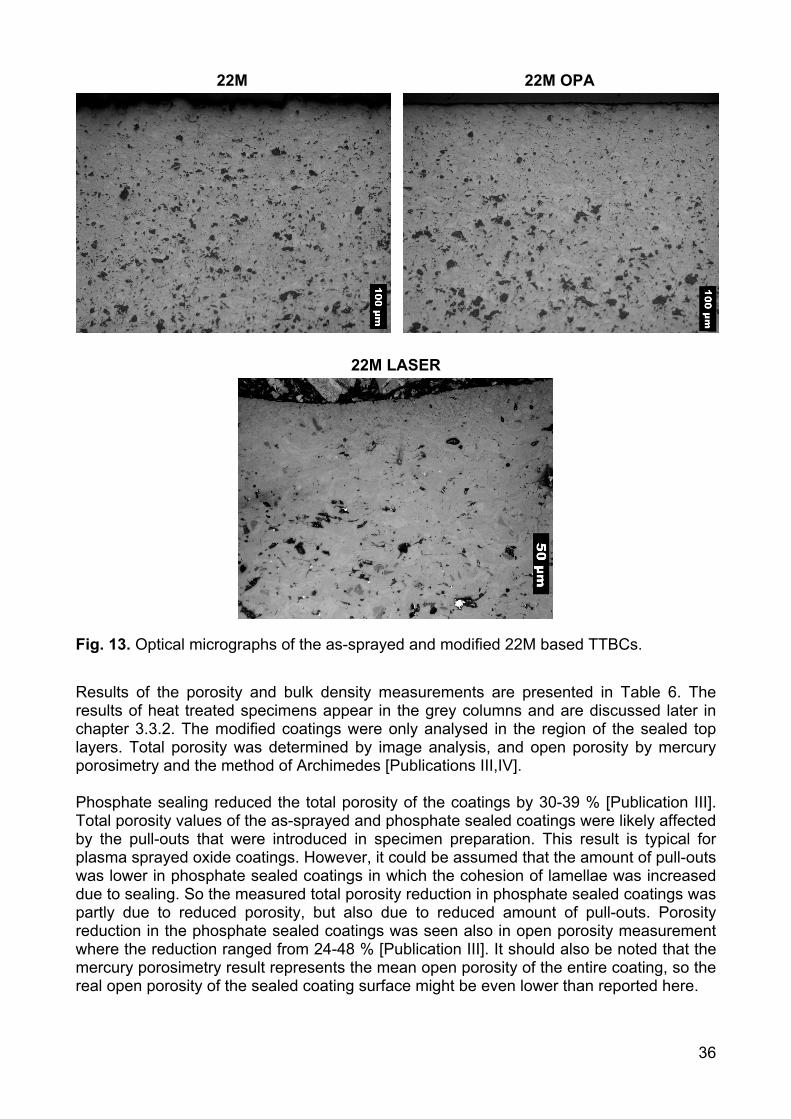
22M 22M OPA
22M LASER
Fig. 13. Optical micrographs of the as-sprayed and modified 22M based TTBCs. Results of the porosity and bulk density measurements are presented in Table 6. The results of heat treated specimens appear in the grey columns and are discussed later in chapter 3.3.2. The modified coatings were only analysed in the region of the sealed top layers. Total porosity was determined by image analysis, and open porosity by mercury porosimetry and the method of Archimedes [Publications III,IV]. Phosphate sealing reduced the total porosity of the coatings by 30-39 % [Publication III]. Total porosity values of the as-sprayed and phosphate sealed coatings were likely affected by the pull-outs that were introduced in specimen preparation. This result is typical for plasma sprayed oxide coatings. However, it could be assumed that the amount of pull-outs was lower in phosphate sealed coatings in which the cohesion of lamellae was increased due to sealing. So the measured total porosity reduction in phosphate sealed coatings was partly due to reduced porosity, but also due to reduced amount of pull-outs. Porosity reduction in the phosphate sealed coatings was seen also in open porosity measurement where the reduction ranged from 24-48 % [Publication III]. It should also be noted that the mercury porosimetry result represents the mean open porosity of the entire coating, so the real open porosity of the sealed coating surface might be even lower than reported here.
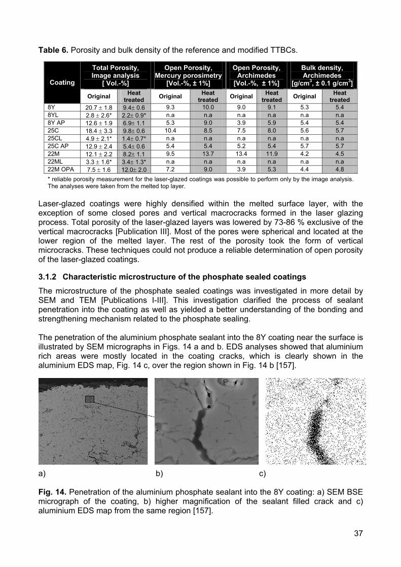
37
Table 6. Porosity and bulk density of the reference and modified TTBCs.
Total Porosity, Image analysis
[ Vol.-%]
Open Porosity, Mercury porosimetry
[Vol.-%, ± 1%]
Open Porosity, Archimedes
[Vol.-%, ± 1%]
Bulk density, Archimedes
[g/cm3, ± 0.1 g/cm3] Coating
Original Heat treated Original Heat
treated Original Heat treated Original Heat
treated 8Y 20.7 ± 1.8 9.4± 0.6 9.3 10.0 9.0 9.1 5.3 5.4 8YL 2.8 ± 2.6* 2.2± 0.9* n.a n.a n.a n.a n.a n.a 8Y AP 12.6 ± 1.9 6.9± 1.1 5.3 9.0 3.9 5.9 5.4 5.4 25C 18.4 ± 3.3 9.8± 0.6 10.4 8.5 7.5 8.0 5.6 5.7 25CL 4.9 ± 2.1* 1.4± 0.7* n.a n.a n.a n.a n.a n.a 25C AP 12.9 ± 2.4 5.4± 0.6 5.4 5.4 5.2 5.4 5.7 5.7 22M 12.1 ± 2.2 8.2± 1.1 9.5 13.7 13.4 11.9 4.2 4.5 22ML 3.3 ± 1.6* 3.4± 1.3* n.a n.a n.a n.a n.a n.a 22M OPA 7.5 ± 1.6 12.0± 2.0 7.2 9.0 3.9 5.3 4.4 4.8 * reliable porosity measurement for the laser-glazed coatings was possible to perform only by the image analysis. The analyses were taken from the melted top layer.
Laser-glazed coatings were highly densified within the melted surface layer, with the exception of some closed pores and vertical macrocracks formed in the laser glazing process. Total porosity of the laser-glazed layers was lowered by 73-86 % exclusive of the vertical macrocracks [Publication III]. Most of the pores were spherical and located at the lower region of the melted layer. The rest of the porosity took the form of vertical microcracks. These techniques could not produce a reliable determination of open porosity of the laser-glazed coatings.
3.1.2 Characteristic microstructure of the phosphate sealed coatings
The microstructure of the phosphate sealed coatings was investigated in more detail by SEM and TEM [Publications I-III]. This investigation clarified the process of sealant penetration into the coating as well as yielded a better understanding of the bonding and strengthening mechanism related to the phosphate sealing. The penetration of the aluminium phosphate sealant into the 8Y coating near the surface is illustrated by SEM micrographs in Figs. 14 a and b. EDS analyses showed that aluminium rich areas were mostly located in the coating cracks, which is clearly shown in the aluminium EDS map, Fig. 14 c, over the region shown in Fig. 14 b [157].
a) b) c) Fig. 14. Penetration of the aluminium phosphate sealant into the 8Y coating: a) SEM BSE micrograph of the coating, b) higher magnification of the sealant filled crack and c) aluminium EDS map from the same region [157].
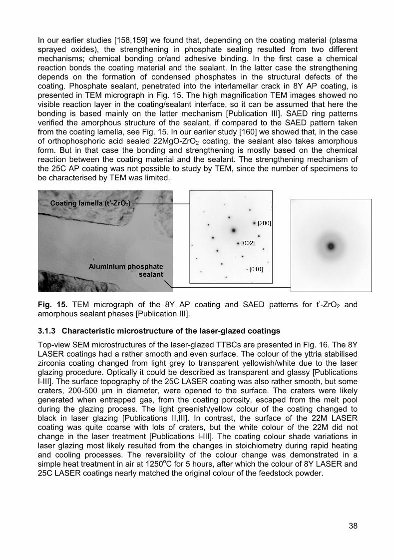
38
In our earlier studies [158,159] we found that, depending on the coating material (plasma sprayed oxides), the strengthening in phosphate sealing resulted from two different mechanisms; chemical bonding or/and adhesive binding. In the first case a chemical reaction bonds the coating material and the sealant. In the latter case the strengthening depends on the formation of condensed phosphates in the structural defects of the coating. Phosphate sealant, penetrated into the interlamellar crack in 8Y AP coating, is presented in TEM micrograph in Fig. 15. The high magnification TEM images showed no visible reaction layer in the coating/sealant interface, so it can be assumed that here the bonding is based mainly on the latter mechanism [Publication III]. SAED ring patterns verified the amorphous structure of the sealant, if compared to the SAED pattern taken from the coating lamella, see Fig. 15. In our earlier study [160] we showed that, in the case of orthophosphoric acid sealed 22MgO-ZrO2 coating, the sealant also takes amorphous form. But in that case the bonding and strengthening is mostly based on the chemical reaction between the coating material and the sealant. The strengthening mechanism of the 25C AP coating was not possible to study by TEM, since the number of specimens to be characterised by TEM was limited.
Fig. 15. TEM micrograph of the 8Y AP coating and SAED patterns for t’-ZrO2 and amorphous sealant phases [Publication III].
3.1.3 Characteristic microstructure of the laser-glazed coatings
Top-view SEM microstructures of the laser-glazed TTBCs are presented in Fig. 16. The 8Y LASER coatings had a rather smooth and even surface. The colour of the yttria stabilised zirconia coating changed from light grey to transparent yellowish/white due to the laser glazing procedure. Optically it could be described as transparent and glassy [Publications I-III]. The surface topography of the 25C LASER coating was also rather smooth, but some craters, 200-500 µm in diameter, were opened to the surface. The craters were likely generated when entrapped gas, from the coating porosity, escaped from the melt pool during the glazing process. The light greenish/yellow colour of the coating changed to black in laser glazing [Publications II,III]. In contrast, the surface of the 22M LASER coating was quite coarse with lots of craters, but the white colour of the 22M did not change in the laser treatment [Publications I-III]. The coating colour shade variations in laser glazing most likely resulted from the changes in stoichiometry during rapid heating and cooling processes. The reversibility of the colour change was demonstrated in a simple heat treatment in air at 1250oC for 5 hours, after which the colour of 8Y LASER and 25C LASER coatings nearly matched the original colour of the feedstock powder.
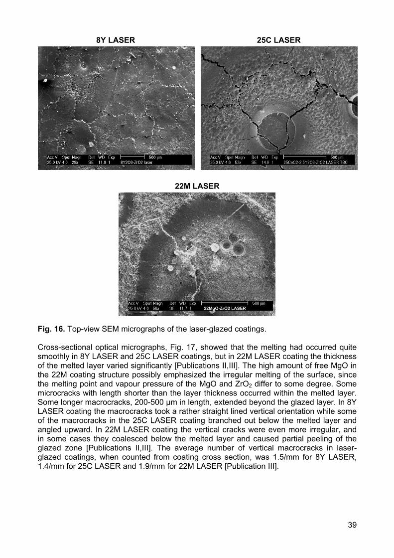
39
8Y LASER 25C LASER
22M LASER
Fig. 16. Top-view SEM micrographs of the laser-glazed coatings. Cross-sectional optical micrographs, Fig. 17, showed that the melting had occurred quite smoothly in 8Y LASER and 25C LASER coatings, but in 22M LASER coating the thickness of the melted layer varied significantly [Publications II,III]. The high amount of free MgO in the 22M coating structure possibly emphasized the irregular melting of the surface, since the melting point and vapour pressure of the MgO and ZrO2 differ to some degree. Some microcracks with length shorter than the layer thickness occurred within the melted layer. Some longer macrocracks, 200-500 µm in length, extended beyond the glazed layer. In 8Y LASER coating the macrocracks took a rather straight lined vertical orientation while some of the macrocracks in the 25C LASER coating branched out below the melted layer and angled upward. In 22M LASER coating the vertical cracks were even more irregular, and in some cases they coalesced below the melted layer and caused partial peeling of the glazed zone [Publications II,III]. The average number of vertical macrocracks in laser-glazed coatings, when counted from coating cross section, was 1.5/mm for 8Y LASER, 1.4/mm for 25C LASER and 1.9/mm for 22M LASER [Publication III].
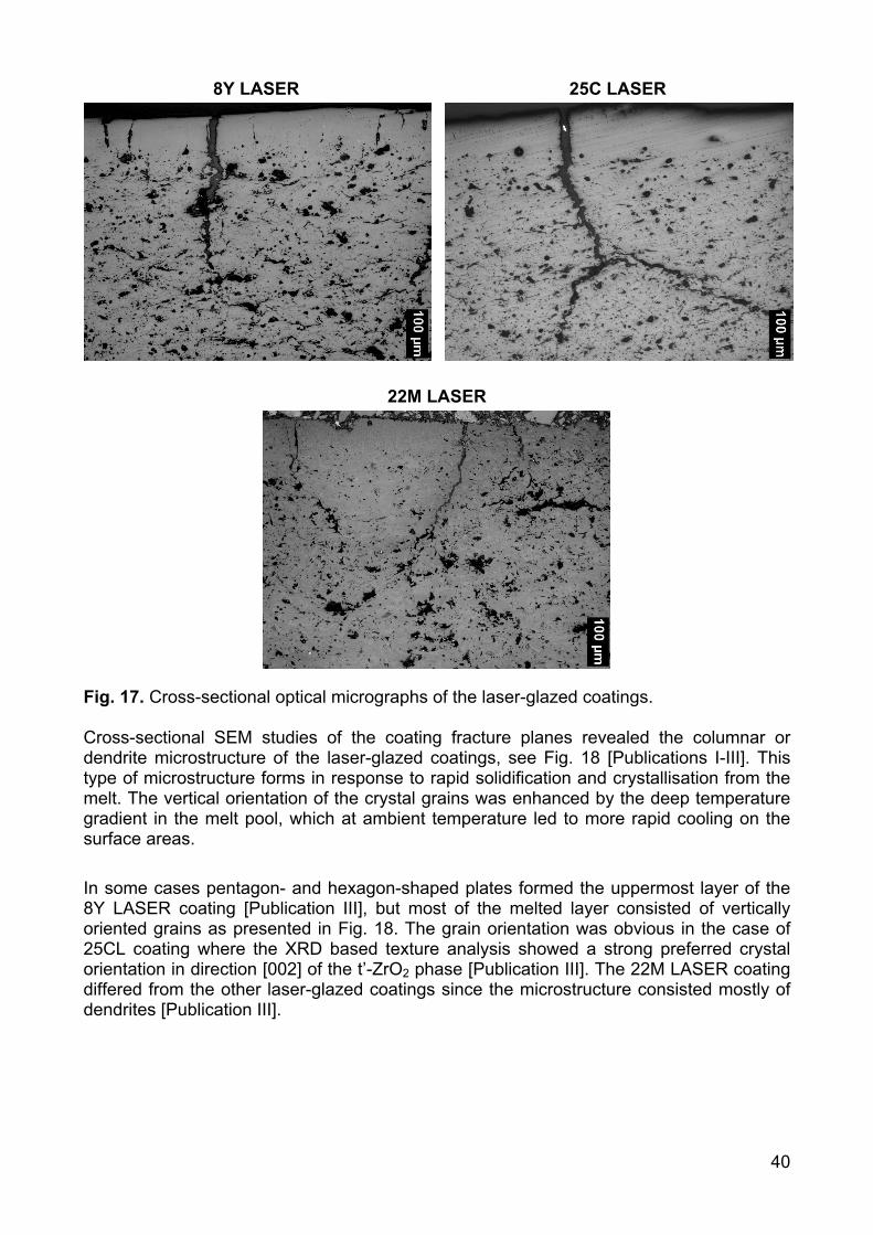
40
8Y LASER 25C LASER
22M LASER
Fig. 17. Cross-sectional optical micrographs of the laser-glazed coatings. Cross-sectional SEM studies of the coating fracture planes revealed the columnar or dendrite microstructure of the laser-glazed coatings, see Fig. 18 [Publications I-III]. This type of microstructure forms in response to rapid solidification and crystallisation from the melt. The vertical orientation of the crystal grains was enhanced by the deep temperature gradient in the melt pool, which at ambient temperature led to more rapid cooling on the surface areas. In some cases pentagon- and hexagon-shaped plates formed the uppermost layer of the 8Y LASER coating [Publication III], but most of the melted layer consisted of vertically oriented grains as presented in Fig. 18. The grain orientation was obvious in the case of 25CL coating where the XRD based texture analysis showed a strong preferred crystal orientation in direction [002] of the t’-ZrO2 phase [Publication III]. The 22M LASER coating differed from the other laser-glazed coatings since the microstructure consisted mostly of dendrites [Publication III].
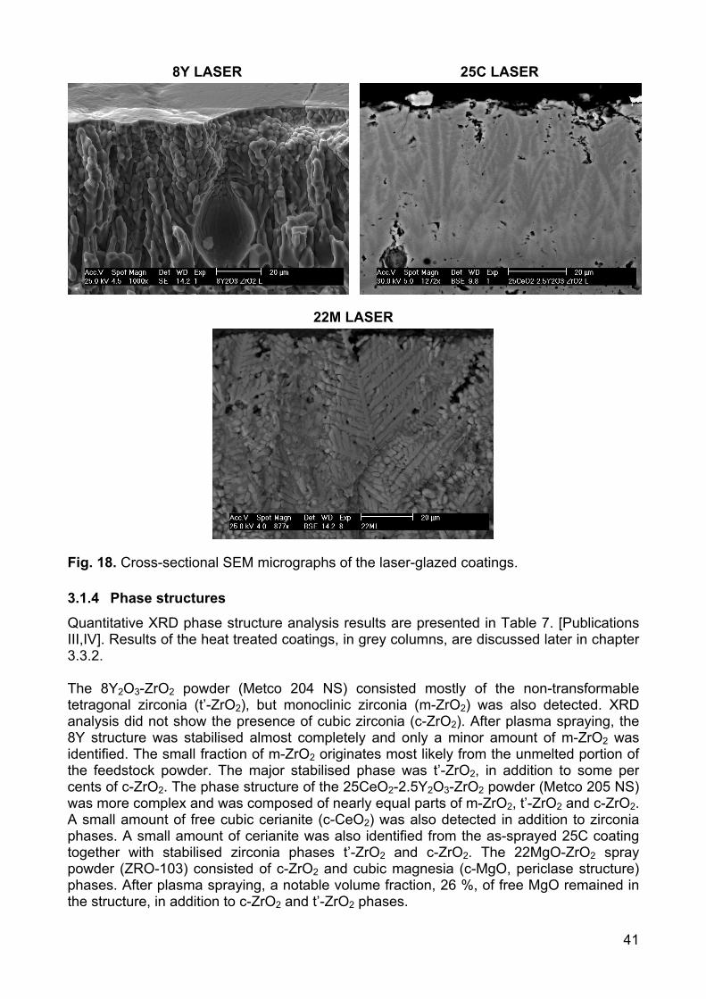
41
8Y LASER 25C LASER
22M LASER
Fig. 18. Cross-sectional SEM micrographs of the laser-glazed coatings.
3.1.4 Phase structures
Quantitative XRD phase structure analysis results are presented in Table 7. [Publications III,IV]. Results of the heat treated coatings, in grey columns, are discussed later in chapter 3.3.2. The 8Y2O3-ZrO2 powder (Metco 204 NS) consisted mostly of the non-transformable tetragonal zirconia (t’-ZrO2), but monoclinic zirconia (m-ZrO2) was also detected. XRD analysis did not show the presence of cubic zirconia (c-ZrO2). After plasma spraying, the 8Y structure was stabilised almost completely and only a minor amount of m-ZrO2 was identified. The small fraction of m-ZrO2 originates most likely from the unmelted portion of the feedstock powder. The major stabilised phase was t’-ZrO2, in addition to some per cents of c-ZrO2. The phase structure of the 25CeO2-2.5Y2O3-ZrO2 powder (Metco 205 NS) was more complex and was composed of nearly equal parts of m-ZrO2, t’-ZrO2 and c-ZrO2. A small amount of free cubic cerianite (c-CeO2) was also detected in addition to zirconia phases. A small amount of cerianite was also identified from the as-sprayed 25C coating together with stabilised zirconia phases t’-ZrO2 and c-ZrO2. The 22MgO-ZrO2 spray powder (ZRO-103) consisted of c-ZrO2 and cubic magnesia (c-MgO, periclase structure) phases. After plasma spraying, a notable volume fraction, 26 %, of free MgO remained in the structure, in addition to c-ZrO2 and t’-ZrO2 phases.
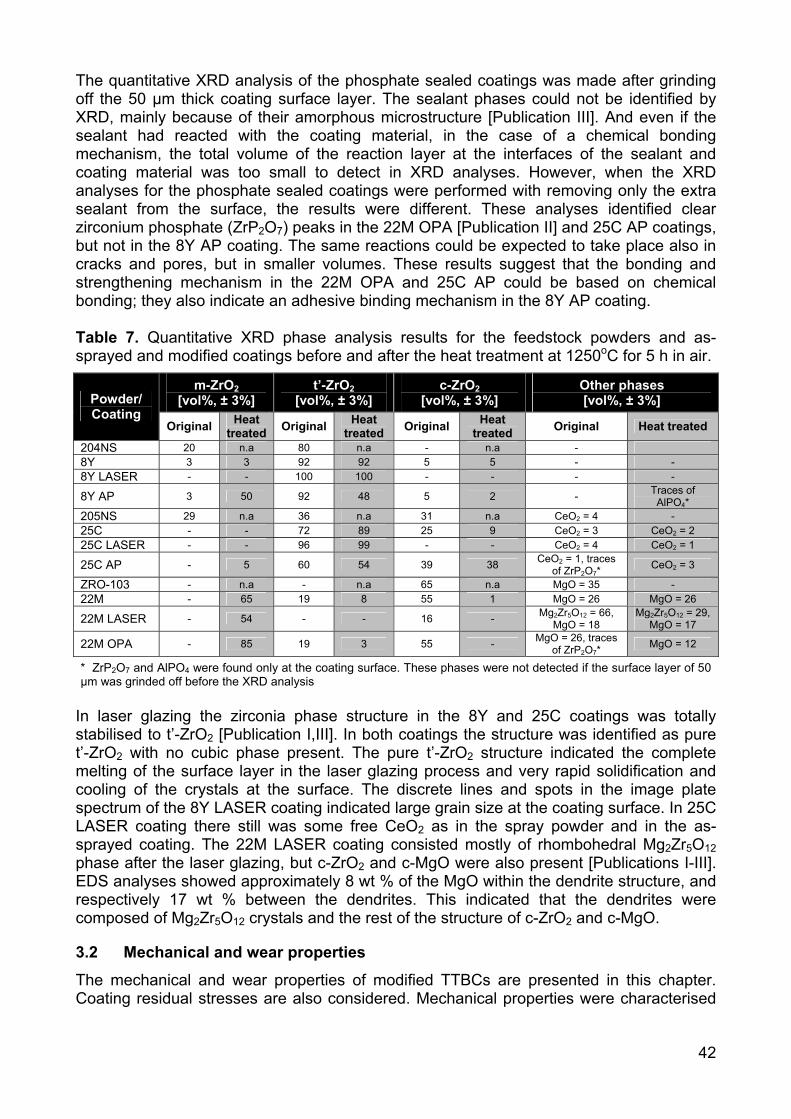
42
The quantitative XRD analysis of the phosphate sealed coatings was made after grinding off the 50 µm thick coating surface layer. The sealant phases could not be identified by XRD, mainly because of their amorphous microstructure [Publication III]. And even if the sealant had reacted with the coating material, in the case of a chemical bonding mechanism, the total volume of the reaction layer at the interfaces of the sealant and coating material was too small to detect in XRD analyses. However, when the XRD analyses for the phosphate sealed coatings were performed with removing only the extra sealant from the surface, the results were different. These analyses identified clear zirconium phosphate (ZrP2O7) peaks in the 22M OPA [Publication II] and 25C AP coatings, but not in the 8Y AP coating. The same reactions could be expected to take place also in cracks and pores, but in smaller volumes. These results suggest that the bonding and strengthening mechanism in the 22M OPA and 25C AP could be based on chemical bonding; they also indicate an adhesive binding mechanism in the 8Y AP coating. Table 7. Quantitative XRD phase analysis results for the feedstock powders and as-sprayed and modified coatings before and after the heat treatment at 1250oC for 5 h in air.
m-ZrO2 [vol%, ± 3%]
t’-ZrO2 [vol%, ± 3%]
c-ZrO2 [vol%, ± 3%]
Other phases [vol%, ± 3%] Powder/
Coating Original Heat
treated Original Heat treated Original Heat
treated Original Heat treated
204NS 20 n.a 80 n.a - n.a - 8Y 3 3 92 92 5 5 - - 8Y LASER - - 100 100 - - - -
8Y AP 3 50 92 48 5 2 - Traces of AlPO4*
205NS 29 n.a 36 n.a 31 n.a CeO2 = 4 - 25C - - 72 89 25 9 CeO2 = 3 CeO2 = 2 25C LASER - - 96 99 - - CeO2 = 4 CeO2 = 1
25C AP - 5 60 54 39 38 CeO2 = 1, traces of ZrP2O7*
CeO2 = 3
ZRO-103 - n.a - n.a 65 n.a MgO = 35 - 22M - 65 19 8 55 1 MgO = 26 MgO = 26
22M LASER - 54 - - 16 - Mg2Zr5O12 = 66, MgO = 18
Mg2Zr5O12 = 29, MgO = 17
22M OPA - 85 19 3 55 - MgO = 26, traces of ZrP2O7*
MgO = 12
* ZrP2O7 and AlPO4 were found only at the coating surface. These phases were not detected if the surface layer of 50 µm was grinded off before the XRD analysis
In laser glazing the zirconia phase structure in the 8Y and 25C coatings was totally stabilised to t’-ZrO2 [Publication I,III]. In both coatings the structure was identified as pure t’-ZrO2 with no cubic phase present. The pure t’-ZrO2 structure indicated the complete melting of the surface layer in the laser glazing process and very rapid solidification and cooling of the crystals at the surface. The discrete lines and spots in the image plate spectrum of the 8Y LASER coating indicated large grain size at the coating surface. In 25C LASER coating there still was some free CeO2 as in the spray powder and in the as-sprayed coating. The 22M LASER coating consisted mostly of rhombohedral Mg2Zr5O12 phase after the laser glazing, but c-ZrO2 and c-MgO were also present [Publications I-III]. EDS analyses showed approximately 8 wt % of the MgO within the dendrite structure, and respectively 17 wt % between the dendrites. This indicated that the dendrites were composed of Mg2Zr5O12 crystals and the rest of the structure of c-ZrO2 and c-MgO.
3.2 Mechanical and wear properties
The mechanical and wear properties of modified TTBCs are presented in this chapter. Coating residual stresses are also considered. Mechanical properties were characterised
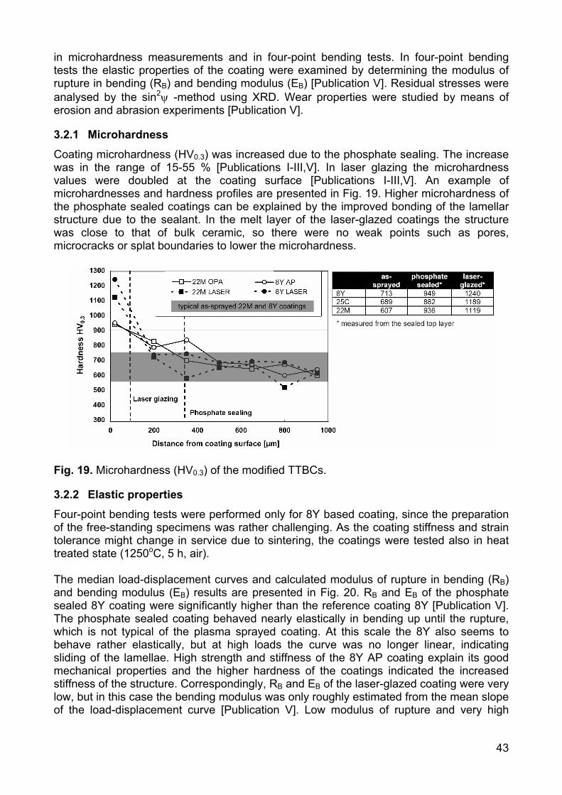
43
in microhardness measurements and in four-point bending tests. In four-point bending tests the elastic properties of the coating were examined by determining the modulus of rupture in bending (RB) and bending modulus (EB) [Publication V]. Residual stresses were analysed by the sin2ψ -method using XRD. Wear properties were studied by means of erosion and abrasion experiments [Publication V].
3.2.1 Microhardness
Coating microhardness (HV0.3) was increased due to the phosphate sealing. The increase was in the range of 15-55 % [Publications I-III,V]. In laser glazing the microhardness values were doubled at the coating surface [Publications I-III,V]. An example of microhardnesses and hardness profiles are presented in Fig. 19. Higher microhardness of the phosphate sealed coatings can be explained by the improved bonding of the lamellar structure due to the sealant. In the melt layer of the laser-glazed coatings the structure was close to that of bulk ceramic, so there were no weak points such as pores, microcracks or splat boundaries to lower the microhardness.
Fig. 19. Microhardness (HV0.3) of the modified TTBCs.
3.2.2 Elastic properties
Four-point bending tests were performed only for 8Y based coating, since the preparation of the free-standing specimens was rather challenging. As the coating stiffness and strain tolerance might change in service due to sintering, the coatings were tested also in heat treated state (1250oC, 5 h, air). The median load-displacement curves and calculated modulus of rupture in bending (RB) and bending modulus (EB) results are presented in Fig. 20. RB and EB of the phosphate sealed 8Y coating were significantly higher than the reference coating 8Y [Publication V]. The phosphate sealed coating behaved nearly elastically in bending up until the rupture, which is not typical of the plasma sprayed coating. At this scale the 8Y also seems to behave rather elastically, but at high loads the curve was no longer linear, indicating sliding of the lamellae. High strength and stiffness of the 8Y AP coating explain its good mechanical properties and the higher hardness of the coatings indicated the increased stiffness of the structure. Correspondingly, RB and EB of the laser-glazed coating were very low, but in this case the bending modulus was only roughly estimated from the mean slope of the load-displacement curve [Publication V]. Low modulus of rupture and very high
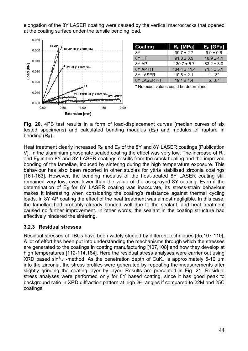
44
elongation of the 8Y LASER coating were caused by the vertical macrocracks that opened at the coating surface under the tensile bending load.
0.000
0.010
0.020
0.030
0.040
0.050
0.060
0.00 0.50 1.00 1.50 2.00
Extension [mm]
Load
[kN
]
8Y LASER8Y LASER HT (1250C, 5h)
8Y
8Y HT (1250C, 5h)
8Y AP HT (1250C, 5h)8Y AP
Fig. 20. 4PB test results in a form of load-displacement curves (median curves of six tested specimens) and calculated bending modulus (EB) and modulus of rupture in bending (RB). Heat treatment clearly increased RB and EB of the 8Y and 8Y LASER coatings [Publication V]. In the aluminium phosphate sealed coating the effect was very low. The increase of RB and EB in the 8Y and 8Y LASER coatings results from the crack healing and the improved bonding of the lamellae, induced by sintering during the high temperature exposure. This behaviour has also been reported in other studies for yttria stabilised zirconia coatings [161-163]. However, the bending modulus of the heat-treated 8Y LASER coating still remained very low, even lower than the value of the as-sprayed 8Y coating. Even if the determination of EB for 8Y LASER coating was inaccurate, its stress-strain behaviour makes it interesting when considering the coating’s resistance against thermal cycling loads. In 8Y AP coating the effect of the heat treatment was almost negligible. In this case, the lamellae had probably already bonded well due to the sealant, and heat treatment caused no further improvement. In other words, the sealant in the coating structure had effectively hindered the sintering.
3.2.3 Residual stresses
Residual stresses of TBCs have been widely studied by different techniques [95,107-110]. A lot of effort has been put into understanding the mechanisms through which the stresses are generated to the coatings in coating manufacturing [107,108] and how they develop at high temperatures [112-114,164]. Here the residual stress analyses were carrier out using XRD based sin2ψ -method. As the penetration depth of CuKα is approximately 5-10 µm into the zirconia, the stress profiles were generated by repeating the measurements after slightly grinding the coating layer by layer. Results are presented in Fig. 21. Residual stress analyses were performed only for 8Y based coating, since it has good peak to background ratio in XRD diffraction pattern at high 2θ -angles if compared to 22M and 25C coatings.
Coating RB [MPa] EB [GPa]8Y 39.7 ± 2.7 9.9 ± 0.6 8Y HT 91.3 ± 3.9 40.9 ± 4.1 8Y AP 130.7 ± 5.7 83.2 ± 3.0 8Y AP HT 134.4 ± 11.4 71.1 ± 5.1 8Y LASER 10.8 ± 2.1 1…3* 8Y LASER HT 19.1 ± 1.4 5…8* * No exact values could be determined

45
-500
-400
-300
-200
-100
0
100
200
0 200 400 600 800
Distance from the surface [µm]
Stre
ss [M
Pa]
8Y REF
8Y LASER
8Y AP
Fig. 21. Residual stress profiles of the 8Y based coatings. Low tensile stresses were found at the surface of the reference coating. At 300 µm below the surface the stresses were already close to zero. In contrast, a strong compressive stress state was detected at the surface of the aluminium phosphate sealed coating. Compressive stresses could be found only in the uppermost layer of the coating, and they were obviously linked to the penetration depth of the sealant. This result correlates also rather well with the microhardness profile of the 8Y AP coating. Compressive stresses at the surface of aluminium phosphate sealed 8Y2O3-ZrO2 coating were already discussed in our earlier study [157]. That study shows that the bond strength increased due to aluminium phosphate sealing. Compressive stresses are likely generated according to the following steps in phosphate sealing: 1) the sealant is impregnated into the coating at room temperature, 2) the structure is heated up to 300oC where the sealant binds the coating structure 3) the stiffness of the coating increases due to the better contact of lamellae, 4) in the cooling stage the sealed coating structure tries to return to its original state due to the metallic substrate, 5) compressive stresses are induced because of the mismatch in coefficients of thermal expansion of metallic substrate and sealed ceramic coating. The stresses induced by phosphate sealing in plasma sprayed oxide coatings are considered in more detail in our ref. [165]. The measurement accuracy of the laser-glazed coating was poor, because the columnar crystal orientation and large grain size of the melt layer complicated the analysis of XRD pattern. Those factors explain the strong variation of the results near the coating surface in Fig. 21. However, at sufficient depth (~350 µm) from the surface the stresses were almost equal in all coatings. Examining the bending of free-standing coatings (specimens that were used in 4PB experiments) detached from the substrates made possible the rough visual estimation of the direction of the macroscopic residual stresses. These visual estimates revealed that the laser-glazed coatings had a slight concave bending tendency, indicating tensile stresses at the coating surface. These tensile stresses likely form in laser glazing by the following procedure: 1) in melt solidification the surface porosity was reduced which led to volume shrinkage of the exposed region, 2) since the solidified layer was well bonded to the coating below, the vertical cracks were formed to relaxing the

46
tensile shrinkage stresses, 3) not all tensile stresses were relaxed, since some residual stresses remained in each dense “segment” between the vertical cracks.
3.2.4 Wear properties
Wear tests were performed only for 8Y and 22M based coatings. Dry erosion tests showed the typical erosion wear behaviour of brittle material considering the particle impact angle. In all coatings the wear volume was highest at an angle of 90o and lowest at 30o. Wear rates as a function of impact angle of erosive are presented in Fig. 22.
Fig. 22. Dry erosion test results of the 8Y and 22M based modified TTBCs. Erosion resistance of both the phosphate sealed coatings was increased significantly [Publication V]. At low impact angles the weight losses were only one fifth that of the reference coatings. In all impact angles the average improvement in erosion resistance was 65-70%. In phosphate sealed coatings the better integrity of the structure probably hindered the erosion-induced crack growth at splat boundaries and prevented the micro-chipping of lamellae. Fig. 23 shows the cross-sectional optical micrographs of the wear traces of the as-sprayed and phosphate sealed coatings at different erosive impact angles.
500
µm
500
µm
Fig. 23. Cross-sectional optical micrographs of the a) 8Y and 8Y AP coatings and b) 22M and 22M OPA coatings after the erosion tests with different impact angles. Laser glazing improved the erosion wear resistance of the yttria stabilised coating on the average by 35%, but the effect was negative on magnesia stabilised coating [Publication V]. The erosion wear traces showed that the wear mechanism of the laser-glazed coatings differed from that of the as-sprayed coatings. The wear surface of the as-sprayed coating indicated that erosion particle impact on the coating surface caused material removal in the scale of one lamella (~1-5 µm). By contrast, in the laser-glazed coating the final fracture, leading to material removal, seemed to occur at the scale of the melted layer. Fig.
0 10 20 30 40 50 60
8Y 8Y AP 8Y LASER
Wei
ght l
oss
[mg]
90 60 30
Impact angle of the erosives
0
20
40
60
80
100
120
140
22M 22M OPA 22M LASER
Wei
ght l
oss
[mg]
90 60 30 Impact angle of the erosives
a)
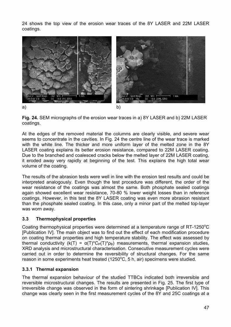
47
24 shows the top view of the erosion wear traces of the 8Y LASER and 22M LASER coatings.
a) b) Fig. 24. SEM micrographs of the erosion wear traces in a) 8Y LASER and b) 22M LASER coatings. At the edges of the removed material the columns are clearly visible, and severe wear seems to concentrate in the cavities. In Fig. 24 the centre line of the wear trace is marked with the white line. The thicker and more uniform layer of the melted zone in the 8Y LASER coating explains its better erosion resistance, compared to 22M LASER coating. Due to the branched and coalesced cracks below the melted layer of 22M LASER coating, it eroded away very rapidly at beginning of the test. This explains the high total wear volume of the coating. The results of the abrasion tests were well in line with the erosion test results and could be interpreted analogously. Even though the test procedure was different, the order of the wear resistance of the coatings was almost the same. Both phosphate sealed coatings again showed excellent wear resistance, 70-80 % lower weight losses than in reference coatings. However, in this test the 8Y LASER coating was even more abrasion resistant than the phosphate sealed coating. In this case, only a minor part of the melted top-layer was worn away.
3.3 Thermophysical properties
Coating thermophysical properties were determined at a temperature range of RT-1250oC [Publication IV]. The main object was to find out the effect of each modification procedure on coating thermal properties and high temperature stability. The effect was assessed by thermal conductivity (k(T) = α(T)*CP(T)*ρB) measurements, thermal expansion studies, XRD analysis and microstructural characterisation. Consecutive measurement cycles were carried out in order to determine the reversibility of structural changes. For the same reason in some experiments heat treated (1250oC, 5 h, air) specimens were studied.
3.3.1 Thermal expansion
The thermal expansion behaviour of the studied TTBCs indicated both irreversible and reversible microstructural changes. The results are presented in Fig. 25. The first type of irreversible change was observed in the form of sintering shrinkage [Publication IV]. This change was clearly seen in the first measurement cycles of the 8Y and 25C coatings at a
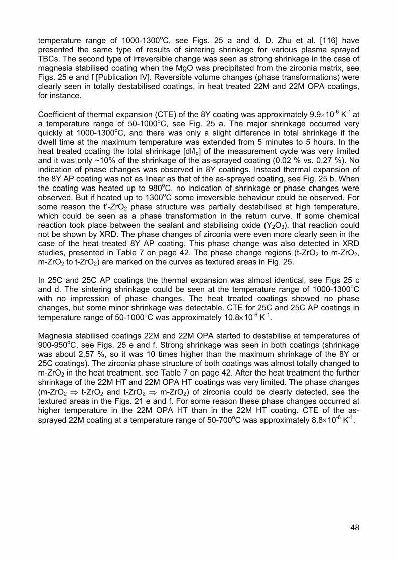
48
temperature range of 1000-1300oC, see Figs. 25 a and d. D. Zhu et al. [116] have presented the same type of results of sintering shrinkage for various plasma sprayed TBCs. The second type of irreversible change was seen as strong shrinkage in the case of magnesia stabilised coating when the MgO was precipitated from the zirconia matrix, see Figs. 25 e and f [Publication IV]. Reversible volume changes (phase transformations) were clearly seen in totally destabilised coatings, in heat treated 22M and 22M OPA coatings, for instance. Coefficient of thermal expansion (CTE) of the 8Y coating was approximately 9.9×10⁻⁶ K-1 at a temperature range of 50-1000oC, see Fig. 25 a. The major shrinkage occurred very quickly at 1000-1300oC, and there was only a slight difference in total shrinkage if the dwell time at the maximum temperature was extended from 5 minutes to 5 hours. In the heat treated coating the total shrinkage [dl/lo] of the measurement cycle was very limited and it was only ~10% of the shrinkage of the as-sprayed coating (0.02 % vs. 0.27 %). No indication of phase changes was observed in 8Y coatings. Instead thermal expansion of the 8Y AP coating was not as linear as that of the as-sprayed coating, see Fig. 25 b. When the coating was heated up to 980oC, no indication of shrinkage or phase changes were observed. But if heated up to 1300oC some irreversible behaviour could be observed. For some reason the t’-ZrO2 phase structure was partially destabilised at high temperature, which could be seen as a phase transformation in the return curve. If some chemical reaction took place between the sealant and stabilising oxide (Y2O3), that reaction could not be shown by XRD. The phase changes of zirconia were even more clearly seen in the case of the heat treated 8Y AP coating. This phase change was also detected in XRD studies, presented in Table 7 on page 42. The phase change regions (t-ZrO2 to m-ZrO2, m-ZrO2 to t-ZrO2) are marked on the curves as textured areas in Fig. 25. In 25C and 25C AP coatings the thermal expansion was almost identical, see Figs 25 c and d. The sintering shrinkage could be seen at the temperature range of 1000-1300oC with no impression of phase changes. The heat treated coatings showed no phase changes, but some minor shrinkage was detectable. CTE for 25C and 25C AP coatings in temperature range of 50-1000oC was approximately 10.8×10⁻⁶ K-1. Magnesia stabilised coatings 22M and 22M OPA started to destabilise at temperatures of 900-950oC, see Figs. 25 e and f. Strong shrinkage was seen in both coatings (shrinkage was about 2,57 %, so it was 10 times higher than the maximum shrinkage of the 8Y or 25C coatings). The zirconia phase structure of both coatings was almost totally changed to m-ZrO2 in the heat treatment, see Table 7 on page 42. After the heat treatment the further shrinkage of the 22M HT and 22M OPA HT coatings was very limited. The phase changes (m-ZrO2 ⇒ t-ZrO2 and t-ZrO2 ⇒ m-ZrO2) of zirconia could be clearly detected, see the textured areas in the Figs. 21 e and f. For some reason these phase changes occurred at higher temperature in the 22M OPA HT than in the 22M HT coating. CTE of the as-sprayed 22M coating at a temperature range of 50-700oC was approximately 8.8×10⁻⁶ K-1.

Fi
g. 2
5. T
herm
al e
xpan
sion
of a
) 8Y
coa
tings
, b) 8
YA
P c
oatin
gs, c
) 25C
coa
tings
, d) 2
5CA
P c
oatin
gs, e
) 22M
coa
tings
and
f)
22M
OP
A c
oatin
gs. M
arke
d ar
eas
in th
e fig
ures
refe
r to
the
stru
ctur
al c
hang
es o
f zirc
onia
.
49
50
3.3.2 Microstructure and phase structure of the heat treated coatings
Total porosity, determined by image analysis, of the as-sprayed and phosphate sealed 8Y and 25C coatings was decreased by 45-58 % due to high temperature exposure [Publication IV]. Total and open porosity results were presented earlier in Table 6 on page 37, see the grey columns. This reduction was more due to the significant decrease of pull-outs than to a true total porosity change. In practice the heat treatment increased the cohesion of the lamellae due to sintering, so they were not so susceptible to be pulled out when cutting, grinding and polishing the cross-sectional specimens. The effect of sintering on 8Y coating is illustrated in SEM micrographs, Fig. 26, by the remaining strings of fine pores and closed cracks at splat boundaries.
Fig. 26. SEM micrographs of heat-treated 8Y coating illustrating the sintering of the structure. String of the fine pores and closed cracks at splat boundaries are marked with black arrows. Open porosity of the 8Y and 25C coatings, determined by mercury porosimetry or Archimedes’ method, remained fairly constant before and after the heat treatment [Publication IV]. Sintering shrinkage seemingly did not affect the open porosity, and mercury porosimetry results showed no clear evidence of the reduction of the very fine pores or microcracks. However, the heat treatment increased the open porosity of the 8Y AP and 25C AP coatings to some degree [Publication IV]. This increase was probably due to the shrinkage of the sealant at high temperatures, caused by the crystallisation of the amorphous structure. Porosity of the heat treated 22M based coatings was difficult to measure and interpret, because the high amount of m-ZrO2 made the structure very brittle. Moreover, the MgO precipitates, which were seen as dark spots in optical micrographs, complicated the image analysis. Quantitative XRD phase analysis results strongly supported the thermal expansion data [Publication IV], see the grey columns in Table 7 on page 42. The t’-ZrO2 phase structure of the 8Y and 8Y LASER coatings did not change in the heat treatment although in 8Y AP coating the tetragonal structure was partially destabilised to m-ZrO2 (50 vol%). After the heat treatment a small amount of AlPO4 was identified at the coating surface, and it could be assumed also that the amorphous sealant in the coating cracks was crystallised. However, the amount of the sealant penetrated into the coating structure was probably too low to detect by XRD. Unfortunately the TEM studies, in which this inference could be verified, were impossible to carry out. Heat treatment had only a slight effect on the phase structure of the 25C and 25C LASER coatings. 25C AP coating was more stable in heat-treatment than 8Y AP and only 5 vol% of m-ZrO2 was detected. The ZrP2O7 phase that
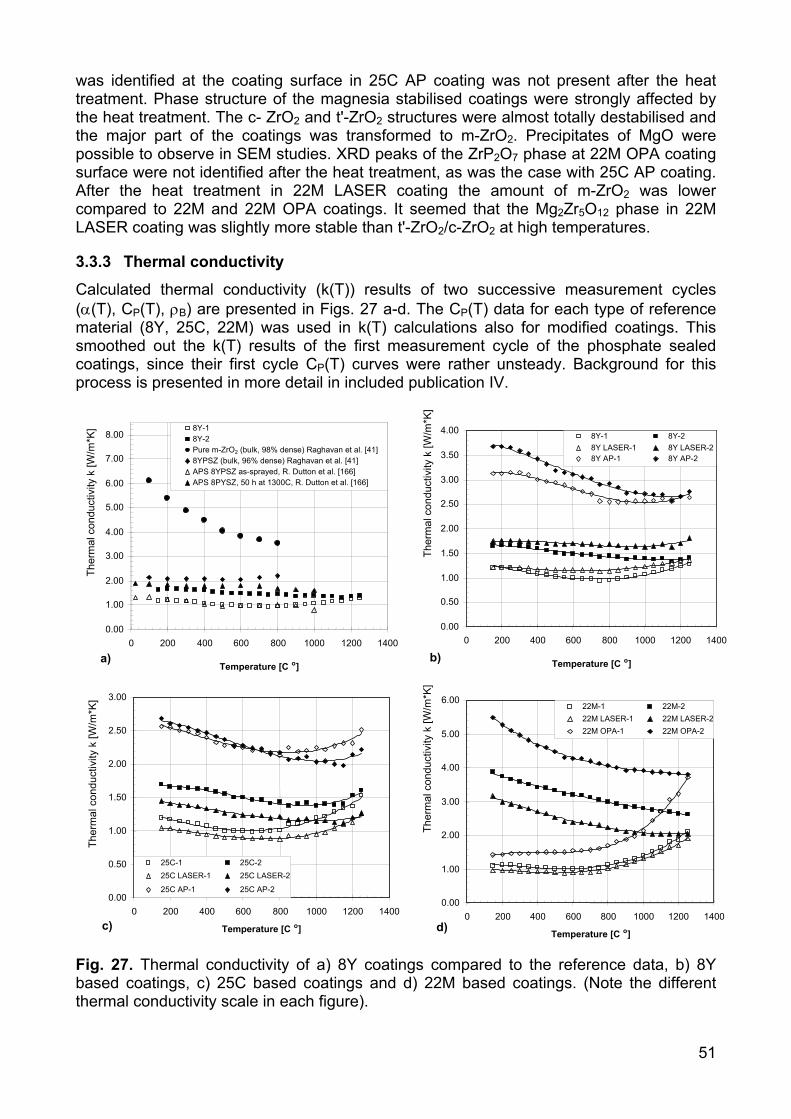
51
was identified at the coating surface in 25C AP coating was not present after the heat treatment. Phase structure of the magnesia stabilised coatings were strongly affected by the heat treatment. The c- ZrO2 and t'-ZrO2 structures were almost totally destabilised and the major part of the coatings was transformed to m-ZrO2. Precipitates of MgO were possible to observe in SEM studies. XRD peaks of the ZrP2O7 phase at 22M OPA coating surface were not identified after the heat treatment, as was the case with 25C AP coating. After the heat treatment in 22M LASER coating the amount of m-ZrO2 was lower compared to 22M and 22M OPA coatings. It seemed that the Mg2Zr5O12 phase in 22M LASER coating was slightly more stable than t'-ZrO2/c-ZrO2 at high temperatures.
3.3.3 Thermal conductivity
Calculated thermal conductivity (k(T)) results of two successive measurement cycles (α(T), CP(T), ρB) are presented in Figs. 27 a-d. The CP(T) data for each type of reference material (8Y, 25C, 22M) was used in k(T) calculations also for modified coatings. This smoothed out the k(T) results of the first measurement cycle of the phosphate sealed coatings, since their first cycle CP(T) curves were rather unsteady. Background for this process is presented in more detail in included publication IV.
Fig. 27. Thermal conductivity of a) 8Y coatings compared to the reference data, b) 8Y based coatings, c) 25C based coatings and d) 22M based coatings. (Note the different thermal conductivity scale in each figure).
0.00 1.00 2.00 3.00 4.00 5.00 6.00 7.00 8.00
0 200 400 600 800 1000 1200 1400
Temperature [C o ]
Ther
mal
con
duct
ivity
k [W
/m*K
] 8Y-1 8Y-2 Pure m-ZrO2 (bulk, 98% dense) Raghavan et al. [41]8YPSZ (bulk, 96% dense) Raghavan et al. [41]APS 8YPSZ as-sprayed, R. Dutton et al. [166] APS 8PYSZ, 50 h at 1300C, R. Dutton et al. [166]
0.00
0.50
1.00
1.50
2.00
2.50
3.00
3.50
4.00
0 200 400 600 800 1000 1200 1400
Temperature [C o ]
Ther
mal
con
duct
ivity
k [W
/m*K
] 8Y-1 8Y-28Y LASER-1 8Y LASER-28Y AP-1 8Y AP-2
0.00
1.00
2.00
3.00
4.00
5.00
6.00
0 200 400 600 800 1000 1200 1400
Temperature [C o ]
Ther
mal
con
duct
ivity
k [W
/m*K
]
22M-1 22M-222M LASER-1 22M LASER-222M OPA-1 22M OPA-2
0.00
0.50
1.00
1.50
2.00
2.50
3.00
0 200 400 600 800 1000 1200 1400
Temperature [C o ]
Ther
mal
con
duct
ivity
k [W
/m*K
]
25C-1 25C-2 25C LASER-1 25C LASER-2 25C AP-1 25C AP-2
a) b)
c) d)
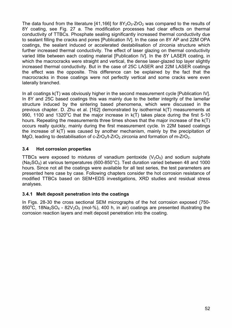
52
The data found from the literature [41,166] for 8Y2O3-ZrO2 was compared to the results of 8Y coating, see Fig. 27 a. The modification processes had clear effects on thermal conductivity of TTBCs. Phosphate sealing significantly increased thermal conductivity due to sealant filling the cracks and pores [Publication IV]. In the case on 8Y AP and 22M OPA coatings, the sealant induced or accelerated destabilisation of zirconia structure which further increased thermal conductivity. The effect of laser glazing on thermal conductivity varied little between each coating material [Publication IV]. In the 8Y LASER coating, in which the macrocracks were straight and vertical, the dense laser-glazed top layer slightly increased thermal conductivity. But in the case of 25C LASER and 22M LASER coatings the effect was the opposite. This difference can be explained by the fact that the macrocracks in those coatings were not perfectly vertical and some cracks were even laterally branched. In all coatings k(T) was obviously higher in the second measurement cycle [Publication IV]. In 8Y and 25C based coatings this was mainly due to the better integrity of the lamellar structure induced by the sintering based phenomena, which were discussed in the previous chapter. D. Zhu et al. [162] demonstrated by isothermal k(T) measurements at 990, 1100 and 1320oC that the major increase in k(T) takes place during the first 5-10 hours. Repeating the measurements three times shows that the major increase of the k(T) occurs really quickly, mainly during the first measurement cycle. In 22M based coatings the increase of k(T) was caused by another mechanism, mainly by the precipitation of MgO, leading to destabilisation of c-ZrO2/t-ZrO2 zirconia and formation of m-ZrO2.
3.4 Hot corrosion properties
TTBCs were exposed to mixtures of vanadium pentoxide (V2O5) and sodium sulphate (Na2SO4) at various temperatures (600-850°C). Test duration varied between 48 and 1000 hours. Since not all the coatings were available for all test series, the test parameters are presented here case by case. Following chapters consider the hot corrosion resistance of modified TTBCs based on SEM+EDS investigations, XRD studies and residual stress analyses.
3.4.1 Melt deposit penetration into the coatings
In Figs. 28-30 the cross sectional SEM micrographs of the hot corrosion exposed (750-850oC, 18Na2SO4 - 82V2O5 (mol-%), 400 h, in air) coatings are presented illustrating the corrosion reaction layers and melt deposit penetration into the coating.
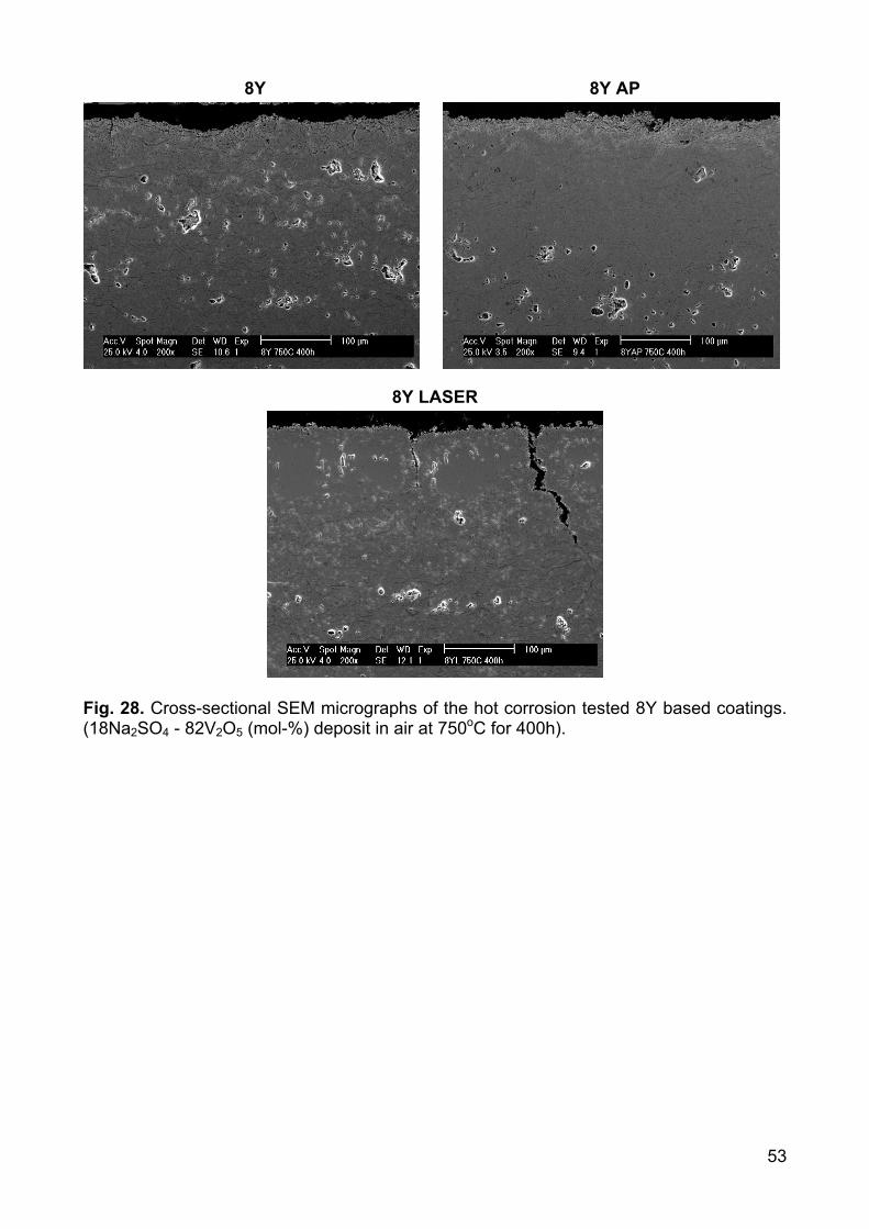
53
8Y 8Y AP
8Y LASER
Fig. 28. Cross-sectional SEM micrographs of the hot corrosion tested 8Y based coatings. (18Na2SO4 - 82V2O5 (mol-%) deposit in air at 750oC for 400h).
54
25C 25C AP
25C LASER
Fig. 29. Cross-sectional SEM micrographs of the hot corrosion tested 25C based coatings. (18Na2SO4 - 82V2O5 (mol-%) deposit in air at 750oC for 400h).
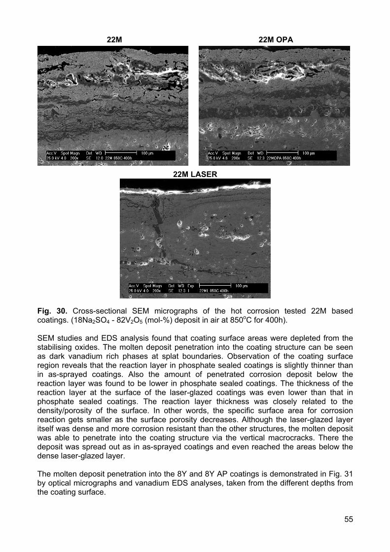
55
22M 22M OPA
22M LASER
Fig. 30. Cross-sectional SEM micrographs of the hot corrosion tested 22M based coatings. (18Na2SO4 - 82V2O5 (mol-%) deposit in air at 850oC for 400h). SEM studies and EDS analysis found that coating surface areas were depleted from the stabilising oxides. The molten deposit penetration into the coating structure can be seen as dark vanadium rich phases at splat boundaries. Observation of the coating surface region reveals that the reaction layer in phosphate sealed coatings is slightly thinner than in as-sprayed coatings. Also the amount of penetrated corrosion deposit below the reaction layer was found to be lower in phosphate sealed coatings. The thickness of the reaction layer at the surface of the laser-glazed coatings was even lower than that in phosphate sealed coatings. The reaction layer thickness was closely related to the density/porosity of the surface. In other words, the specific surface area for corrosion reaction gets smaller as the surface porosity decreases. Although the laser-glazed layer itself was dense and more corrosion resistant than the other structures, the molten deposit was able to penetrate into the coating structure via the vertical macrocracks. There the deposit was spread out as in as-sprayed coatings and even reached the areas below the dense laser-glazed layer. The molten deposit penetration into the 8Y and 8Y AP coatings is demonstrated in Fig. 31 by optical micrographs and vanadium EDS analyses, taken from the different depths from the coating surface.
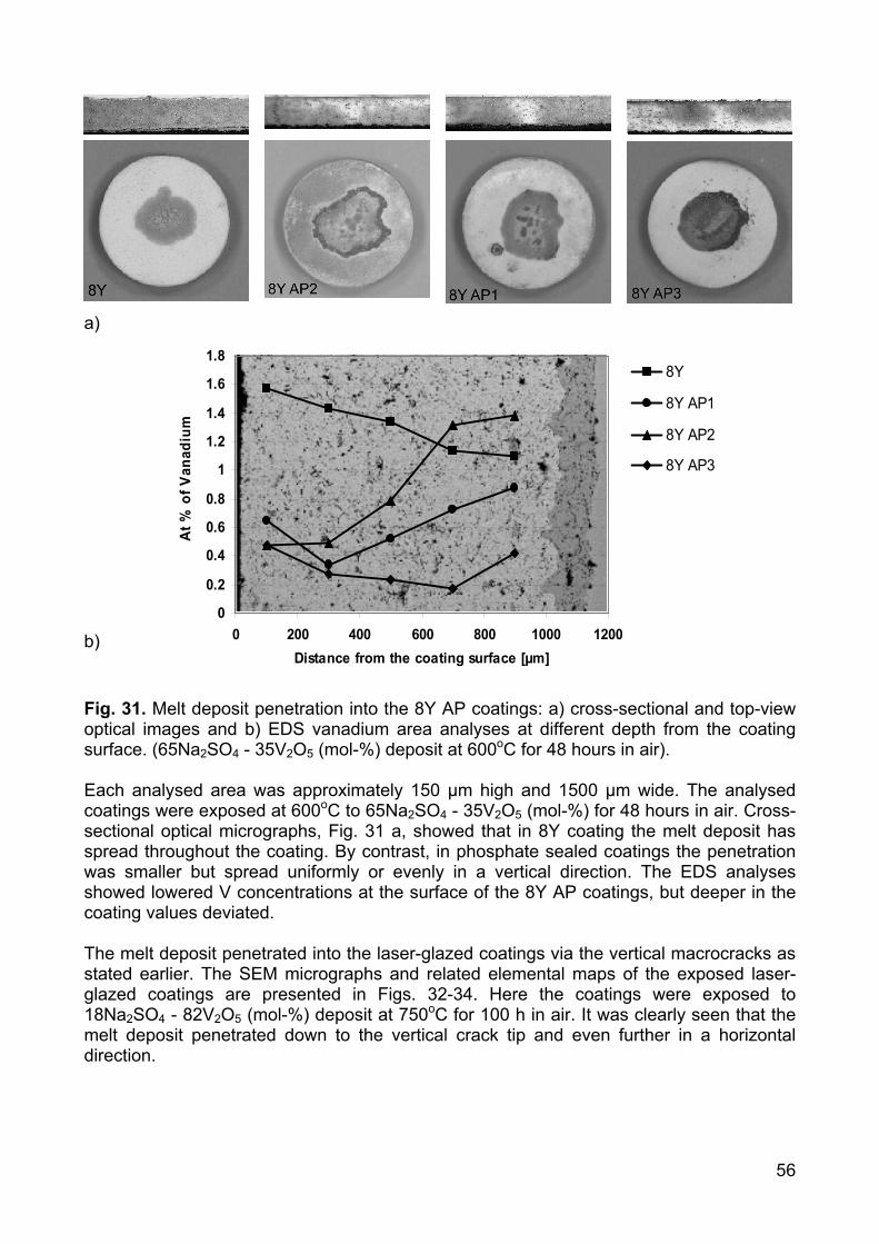
56
0
0.2
0.4
0.6
0.8
1
1.2
1.4
1.6
1.8
0 200 400 600 800 1000 1200Distance from the coating surface [µm]
At %
of V
anad
ium
8Y
8Y AP1
8Y AP2
8Y AP3
a)
b) Fig. 31. Melt deposit penetration into the 8Y AP coatings: a) cross-sectional and top-view optical images and b) EDS vanadium area analyses at different depth from the coating surface. (65Na2SO4 - 35V2O5 (mol-%) deposit at 600oC for 48 hours in air). Each analysed area was approximately 150 µm high and 1500 µm wide. The analysed coatings were exposed at 600oC to 65Na2SO4 - 35V2O5 (mol-%) for 48 hours in air. Cross-sectional optical micrographs, Fig. 31 a, showed that in 8Y coating the melt deposit has spread throughout the coating. By contrast, in phosphate sealed coatings the penetration was smaller but spread uniformly or evenly in a vertical direction. The EDS analyses showed lowered V concentrations at the surface of the 8Y AP coatings, but deeper in the coating values deviated. The melt deposit penetrated into the laser-glazed coatings via the vertical macrocracks as stated earlier. The SEM micrographs and related elemental maps of the exposed laser-glazed coatings are presented in Figs. 32-34. Here the coatings were exposed to 18Na2SO4 - 82V2O5 (mol-%) deposit at 750oC for 100 h in air. It was clearly seen that the melt deposit penetrated down to the vertical crack tip and even further in a horizontal direction.
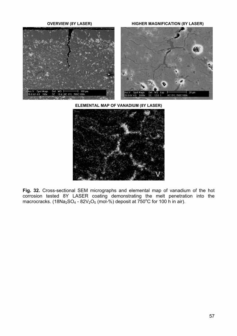
57
OVERVIEW (8Y LASER) HIGHER MAGNIFICATION (8Y LASER)
ELEMENTAL MAP OF VANADIUM (8Y LASER)
Fig. 32. Cross-sectional SEM micrographs and elemental map of vanadium of the hot corrosion tested 8Y LASER coating demonstrating the melt penetration into the macrocracks. (18Na2SO4 - 82V2O5 (mol-%) deposit at 750oC for 100 h in air).
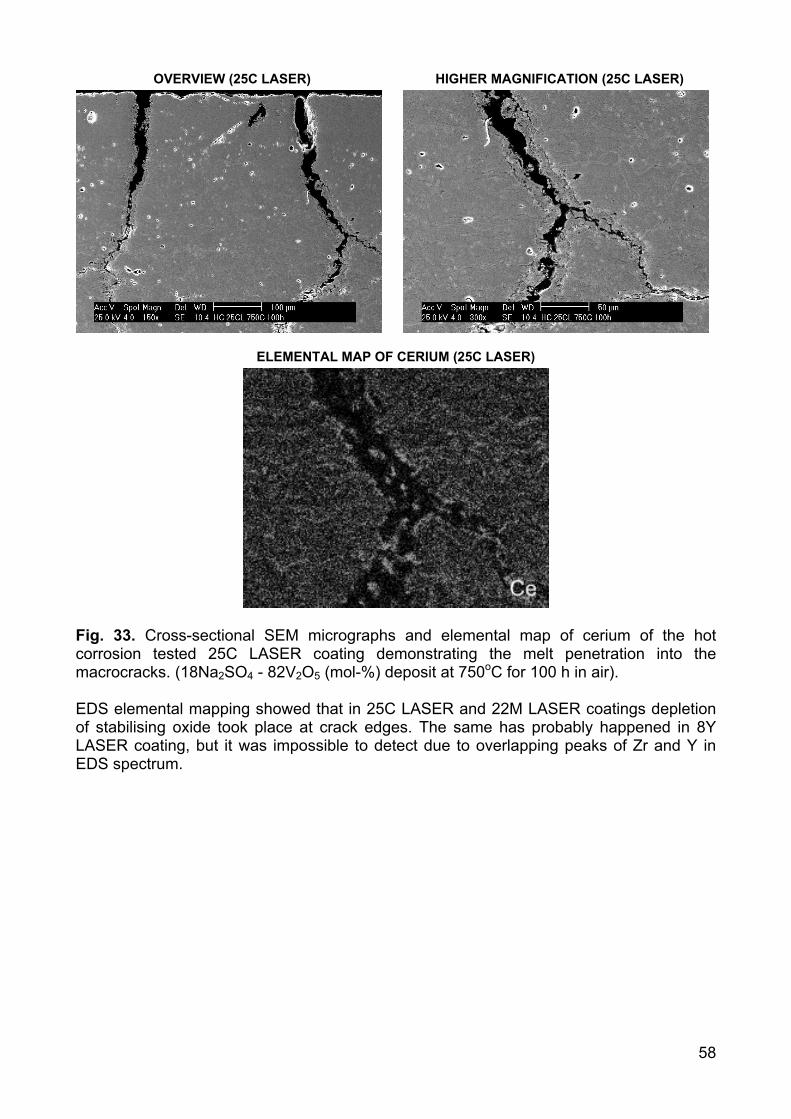
58
OVERVIEW (25C LASER) HIGHER MAGNIFICATION (25C LASER)
ELEMENTAL MAP OF CERIUM (25C LASER)
Fig. 33. Cross-sectional SEM micrographs and elemental map of cerium of the hot corrosion tested 25C LASER coating demonstrating the melt penetration into the macrocracks. (18Na2SO4 - 82V2O5 (mol-%) deposit at 750oC for 100 h in air). EDS elemental mapping showed that in 25C LASER and 22M LASER coatings depletion of stabilising oxide took place at crack edges. The same has probably happened in 8Y LASER coating, but it was impossible to detect due to overlapping peaks of Zr and Y in EDS spectrum.
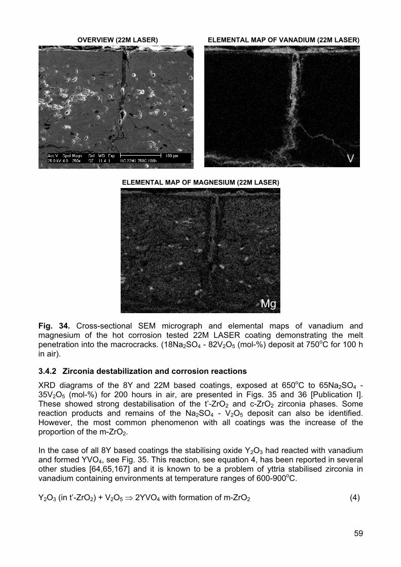
59
OVERVIEW (22M LASER) ELEMENTAL MAP OF VANADIUM (22M LASER)
ELEMENTAL MAP OF MAGNESIUM (22M LASER)
Fig. 34. Cross-sectional SEM micrograph and elemental maps of vanadium and magnesium of the hot corrosion tested 22M LASER coating demonstrating the melt penetration into the macrocracks. (18Na2SO4 - 82V2O5 (mol-%) deposit at 750oC for 100 h in air).
3.4.2 Zirconia destabilization and corrosion reactions
XRD diagrams of the 8Y and 22M based coatings, exposed at 650oC to 65Na2SO4 - 35V2O5 (mol-%) for 200 hours in air, are presented in Figs. 35 and 36 [Publication I]. These showed strong destabilisation of the t’-ZrO2 and c-ZrO2 zirconia phases. Some reaction products and remains of the Na2SO4 - V2O5 deposit can also be identified. However, the most common phenomenon with all coatings was the increase of the proportion of the m-ZrO2. In the case of all 8Y based coatings the stabilising oxide Y2O3 had reacted with vanadium and formed YVO4, see Fig. 35. This reaction, see equation 4, has been reported in several other studies [64,65,167] and it is known to be a problem of yttria stabilised zirconia in vanadium containing environments at temperature ranges of 600-900oC. Y2O3 (in t’-ZrO2) + V2O5 ⇒ 2YVO4 with formation of m-ZrO2 (4)
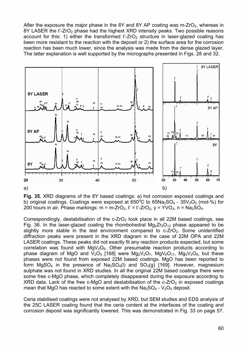
60
After the exposure the major phase in the 8Y and 8Y AP coating was m-ZrO2, whereas in 8Y LASER the t’-ZrO2 phase had the highest XRD intensity peaks. Two possible reasons account for this: 1) either the transformed t’-ZrO2 structure in laser-glazed coating has been more resistant to the reaction with the deposit or 2) the surface area for the corrosion reaction has been much lower, since the analysis was made from the dense glazed layer. The latter explanation is well supported by the micrographs presented in Figs. 28 and 32.
a) b) Fig. 35. XRD diagrams of the 8Y based coatings: a) hot corrosion exposed coatings and b) original coatings. Coatings were exposed at 650oC to 65Na2SO4 - 35V2O5 (mol-%) for 200 hours in air. Phase markings: m = m-ZrO2, t’ = t’-ZrO2, y = YVO4, n = Na2SO4. Correspondingly, destabilisation of the c-ZrO2 took place in all 22M based coatings, see Fig. 36. In the laser-glazed coating the rhombohedral Mg2Zr5O12 phase appeared to be slightly more stable in the test environment compared to c-ZrO2. Some unidentified diffraction peaks were present in the XRD diagram in the case of 22M OPA and 22M LASER coatings. These peaks did not exactly fit any reaction products expected, but some correlation was found with MgV2O6. Other presumable reaction products according to phase diagram of MgO and V2O5 [168] were Mg2V2O7, MgV6O17, Mg3V2O8, but these phases were not found from exposed 22M based coatings. MgO has been reported to form MgSO4 in the presence of Na2SO4(l) and SO3(g) [169]. However, magnesium sulphate was not found in XRD studies. In all the original 22M based coatings there were some free c-MgO phase, which completely disappeared during the exposure according to XRD data. Lack of the free c-MgO and destabilisation of the c-ZrO2 in exposed coatings mean that MgO has reacted to some extent with the Na2SO4 - V2O5 deposit. Ceria stabilised coatings were not analysed by XRD, but SEM studies and EDS analysis of the 25C LASER coating found that the ceria content at the interfaces of the coating and corrosion deposit was significantly lowered. This was demonstrated in Fig. 33 on page 57.
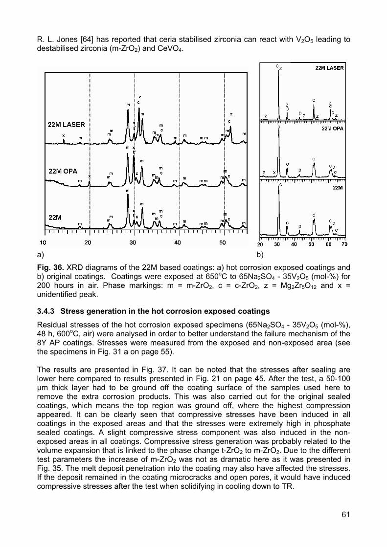
61
R. L. Jones [64] has reported that ceria stabilised zirconia can react with V2O5 leading to destabilised zirconia (m-ZrO2) and CeVO4.
a) b) Fig. 36. XRD diagrams of the 22M based coatings: a) hot corrosion exposed coatings and b) original coatings. Coatings were exposed at 650oC to 65Na2SO4 - 35V2O5 (mol-%) for 200 hours in air. Phase markings: m = m-ZrO2, c = c-ZrO2, z = Mg2Zr5O12 and x = unidentified peak.
3.4.3 Stress generation in the hot corrosion exposed coatings
Residual stresses of the hot corrosion exposed specimens (65Na2SO4 - 35V2O5 (mol-%), 48 h, 600oC, air) were analysed in order to better understand the failure mechanism of the 8Y AP coatings. Stresses were measured from the exposed and non-exposed area (see the specimens in Fig. 31 a on page 55). The results are presented in Fig. 37. It can be noted that the stresses after sealing are lower here compared to results presented in Fig. 21 on page 45. After the test, a 50-100 µm thick layer had to be ground off the coating surface of the samples used here to remove the extra corrosion products. This was also carried out for the original sealed coatings, which means the top region was ground off, where the highest compression appeared. It can be clearly seen that compressive stresses have been induced in all coatings in the exposed areas and that the stresses were extremely high in phosphate sealed coatings. A slight compressive stress component was also induced in the non-exposed areas in all coatings. Compressive stress generation was probably related to the volume expansion that is linked to the phase change t-ZrO2 to m-ZrO2. Due to the different test parameters the increase of m-ZrO2 was not as dramatic here as it was presented in Fig. 35. The melt deposit penetration into the coating may also have affected the stresses. If the deposit remained in the coating microcracks and open pores, it would have induced compressive stresses after the test when solidifying in cooling down to TR.
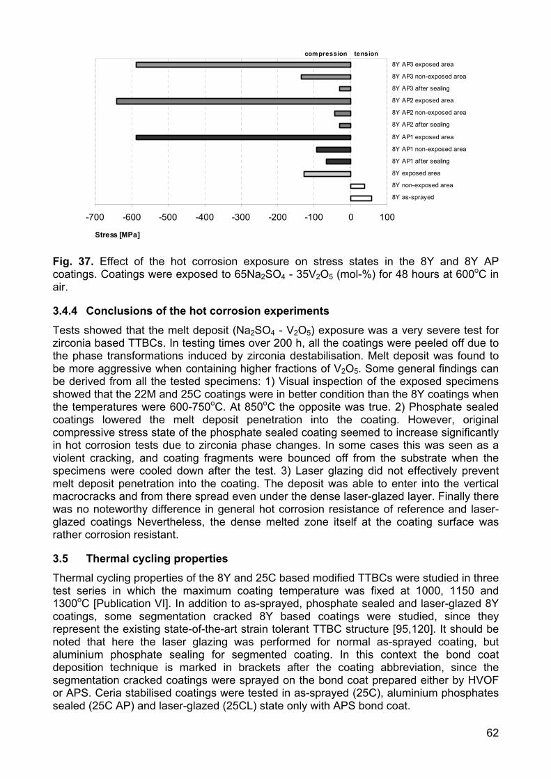
62
-700 -600 -500 -400 -300 -200 -100 0 100
8Y as-sprayed
8Y non-exposed area
8Y exposed area
8Y AP1 after sealing
8Y AP1 non-exposed area
8Y AP1 exposed area
8Y AP2 after sealing
8Y AP2 non-exposed area
8Y AP2 exposed area
8Y AP3 after sealing
8Y AP3 non-exposed area
8Y AP3 exposed area
Stress [MPa]
compression tension
Fig. 37. Effect of the hot corrosion exposure on stress states in the 8Y and 8Y AP coatings. Coatings were exposed to 65Na2SO4 - 35V2O5 (mol-%) for 48 hours at 600oC in air.
3.4.4 Conclusions of the hot corrosion experiments
Tests showed that the melt deposit (Na2SO4 - V2O5) exposure was a very severe test for zirconia based TTBCs. In testing times over 200 h, all the coatings were peeled off due to the phase transformations induced by zirconia destabilisation. Melt deposit was found to be more aggressive when containing higher fractions of V2O5. Some general findings can be derived from all the tested specimens: 1) Visual inspection of the exposed specimens showed that the 22M and 25C coatings were in better condition than the 8Y coatings when the temperatures were 600-750oC. At 850oC the opposite was true. 2) Phosphate sealed coatings lowered the melt deposit penetration into the coating. However, original compressive stress state of the phosphate sealed coating seemed to increase significantly in hot corrosion tests due to zirconia phase changes. In some cases this was seen as a violent cracking, and coating fragments were bounced off from the substrate when the specimens were cooled down after the test. 3) Laser glazing did not effectively prevent melt deposit penetration into the coating. The deposit was able to enter into the vertical macrocracks and from there spread even under the dense laser-glazed layer. Finally there was no noteworthy difference in general hot corrosion resistance of reference and laser-glazed coatings Nevertheless, the dense melted zone itself at the coating surface was rather corrosion resistant.
3.5 Thermal cycling properties
Thermal cycling properties of the 8Y and 25C based modified TTBCs were studied in three test series in which the maximum coating temperature was fixed at 1000, 1150 and 1300oC [Publication VI]. In addition to as-sprayed, phosphate sealed and laser-glazed 8Y coatings, some segmentation cracked 8Y based coatings were studied, since they represent the existing state-of-the-art strain tolerant TTBC structure [95,120]. It should be noted that here the laser glazing was performed for normal as-sprayed coating, but aluminium phosphate sealing for segmented coating. In this context the bond coat deposition technique is marked in brackets after the coating abbreviation, since the segmentation cracked coatings were sprayed on the bond coat prepared either by HVOF or APS. Ceria stabilised coatings were tested in as-sprayed (25C), aluminium phosphates sealed (25C AP) and laser-glazed (25CL) state only with APS bond coat.
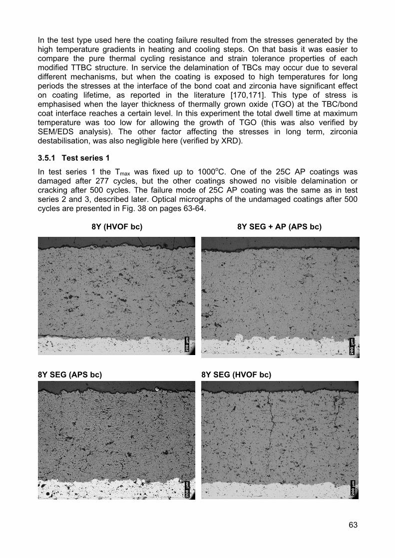
63
In the test type used here the coating failure resulted from the stresses generated by the high temperature gradients in heating and cooling steps. On that basis it was easier to compare the pure thermal cycling resistance and strain tolerance properties of each modified TTBC structure. In service the delamination of TBCs may occur due to several different mechanisms, but when the coating is exposed to high temperatures for long periods the stresses at the interface of the bond coat and zirconia have significant effect on coating lifetime, as reported in the literature [170,171]. This type of stress is emphasised when the layer thickness of thermally grown oxide (TGO) at the TBC/bond coat interface reaches a certain level. In this experiment the total dwell time at maximum temperature was too low for allowing the growth of TGO (this was also verified by SEM/EDS analysis). The other factor affecting the stresses in long term, zirconia destabilisation, was also negligible here (verified by XRD).
3.5.1 Test series 1
In test series 1 the Tmax was fixed up to 1000oC. One of the 25C AP coatings was damaged after 277 cycles, but the other coatings showed no visible delamination or cracking after 500 cycles. The failure mode of 25C AP coating was the same as in test series 2 and 3, described later. Optical micrographs of the undamaged coatings after 500 cycles are presented in Fig. 38 on pages 63-64.
8Y (HVOF bc) 8Y SEG + AP (APS bc)
8Y SEG (APS bc) 8Y SEG (HVOF bc)

64
8Y LASER (APS bc) 25C
25C AP 25C LASER
Fig. 38. Optical micrographs of the modified coatings after the 500 cycles in test series 1 (Tmax = 1000±50oC). Some microstructural changes took place in the coatings during the test series 1. In reference to 8Y (HVOF bc) coating, a horizontal crack slightly above the bond coat indicated that the coating delamination process had already started. The segmentation cracked coatings 8Y SEG (APS bc) and 8Y SEG (HVOF bc) and the phosphate sealed 8Y SEG + AP (APS bc) coating did not show any changes. In laser-glazed coating a horizontal crack appeared within the melted top layer, but it probably had formed during laser glazing or in the specimen cutting process as in the thermal cycling test. Rather pronounced microstructural changes were seen in the 25C based coatings. Some vertical macrocracks, comparable to segmentation cracks in 8Y SEG coatings, had formed in the 25C coating. In the 25C AP coating these cracks, with plenty of branched horizontal elements, appeared even more clearly. This type of crack structure also formed in the 25C LASER coating in laser glazing process, but the length of macrocracks and number and length of branching cracks increased in the test. A horizontal crack, propagated from the edge of the specimen, was also seen near the bond coat of 25C LASER coating.
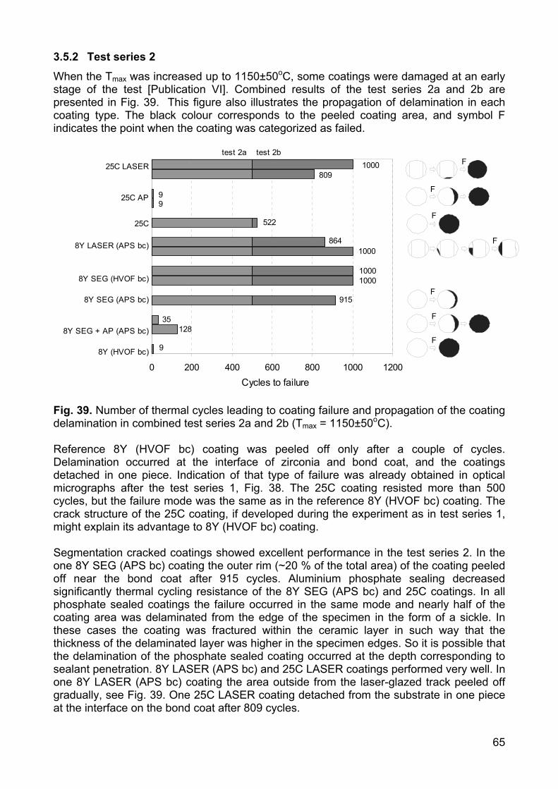
65
3.5.2 Test series 2
When the Tmax was increased up to 1150±50oC, some coatings were damaged at an early stage of the test [Publication VI]. Combined results of the test series 2a and 2b are presented in Fig. 39. This figure also illustrates the propagation of delamination in each coating type. The black colour corresponds to the peeled coating area, and symbol F indicates the point when the coating was categorized as failed.
0 200 400 600 800 1000 1200Cycles to failure
9
35128
915
10001000
1000864
522
99
809100025C LASER
25C AP
25C
8Y LASER (APS bc)
8Y SEG (HVOF bc)
8Y SEG (APS bc)
8Y SEG + AP (APS bc)
8Y (HVOF bc)
test 2a test 2bF
F
F
F
F
F
F
Fig. 39. Number of thermal cycles leading to coating failure and propagation of the coating delamination in combined test series 2a and 2b (Tmax = 1150±50oC). Reference 8Y (HVOF bc) coating was peeled off only after a couple of cycles. Delamination occurred at the interface of zirconia and bond coat, and the coatings detached in one piece. Indication of that type of failure was already obtained in optical micrographs after the test series 1, Fig. 38. The 25C coating resisted more than 500 cycles, but the failure mode was the same as in the reference 8Y (HVOF bc) coating. The crack structure of the 25C coating, if developed during the experiment as in test series 1, might explain its advantage to 8Y (HVOF bc) coating. Segmentation cracked coatings showed excellent performance in the test series 2. In the one 8Y SEG (APS bc) coating the outer rim (~20 % of the total area) of the coating peeled off near the bond coat after 915 cycles. Aluminium phosphate sealing decreased significantly thermal cycling resistance of the 8Y SEG (APS bc) and 25C coatings. In all phosphate sealed coatings the failure occurred in the same mode and nearly half of the coating area was delaminated from the edge of the specimen in the form of a sickle. In these cases the coating was fractured within the ceramic layer in such way that the thickness of the delaminated layer was higher in the specimen edges. So it is possible that the delamination of the phosphate sealed coating occurred at the depth corresponding to sealant penetration. 8Y LASER (APS bc) and 25C LASER coatings performed very well. In one 8Y LASER (APS bc) coating the area outside from the laser-glazed track peeled off gradually, see Fig. 39. One 25C LASER coating detached from the substrate in one piece at the interface on the bond coat after 809 cycles.
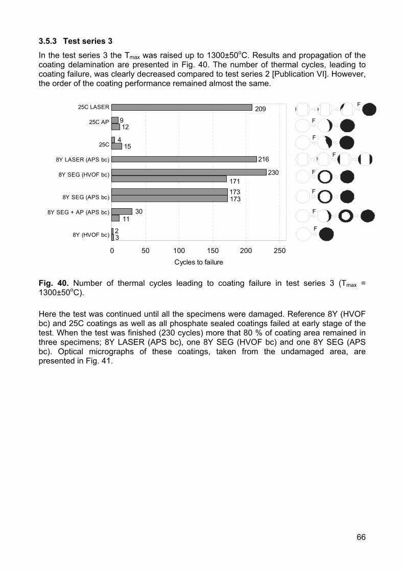
66
3.5.3 Test series 3
In the test series 3 the Tmax was raised up to 1300±50oC. Results and propagation of the coating delamination are presented in Fig. 40. The number of thermal cycles, leading to coating failure, was clearly decreased compared to test series 2 [Publication VI]. However, the order of the coating performance remained almost the same.
32
173
230
216
15
129
173
209
4
3011
171
0 50 100 150 200 250Cycles to failure
25C LASER
25C AP
25C
8Y LASER (APS bc)
8Y SEG (HVOF bc)
8Y SEG (APS bc)
8Y SEG + AP (APS bc)
8Y (HVOF bc)
F
F
F
F
F
F
F
F
Fig. 40. Number of thermal cycles leading to coating failure in test series 3 (Tmax = 1300±50oC). Here the test was continued until all the specimens were damaged. Reference 8Y (HVOF bc) and 25C coatings as well as all phosphate sealed coatings failed at early stage of the test. When the test was finished (230 cycles) more that 80 % of coating area remained in three specimens; 8Y LASER (APS bc), one 8Y SEG (HVOF bc) and one 8Y SEG (APS bc). Optical micrographs of these coatings, taken from the undamaged area, are presented in Fig. 41.

67
8Y SEG (APS bc) 8Y SEG (HVOF bc)
8Y LASER
Fig. 41. Optical micrographs of the modified TTBCs after 230 thermal cycles (Tmax = 1300±50oC).
3.5.4 Discussion of the test results and failure modes
The delamination of the coating started in all cases from the specimen edge region; see the propagation of the delamination of each type of coating in Figs. 39 and 40. The failure mode of each coating type was almost equivalent in all test series. The edge regions were most sensitive to coating failure, because there the heating and cooling occurred most rapidly. Thermal cycling resistance of the reference coatings 8Y (HVOF bc) and 25C was poor. Coatings peeled off in one piece at the bond coat interface indicating good coating integrity but low strain tolerance. The opposite behaviour was found in segmentation cracked and laser-glazed coatings. Both the 8Y SEG (HVOF bc) and 8Y SEG (APS bc) coatings were found to have excellent thermal cycling resistance. The slightly better thermal cycling resistance of the 8Y SEG (HVOF bc) coating could be explained by the original segmentation crack structure of these two coatings. The average segmentation crack length in 8Y SEG (HVOF bc) coating
68
was at least twice as high as in 8Y SEG (APS bc) coating (300-800 µm vs. 100-300 µm). The cracks were also more open in the original 8Y SEG (HVOF bc) coating. The effect of HVOF and APS bond coat was difficult to interpret here, since there were also differences in zirconia coatings that were prepared separately. However, our earlier study [93] showed that there is no difference in thermal cycling resistance whether the zirconia was deposited onto VPS, HVOF of APS sprayed bond coat. The laser-glazed coatings also showed excellent thermal cycling resistance. In the 8Y LASER (APS bc) coating only the segments, outside the laser-glazed track, were peeled off and the laser-glazed area remained unaffected. 25C LASER coatings also managed well although their failure mode differed from the 8Y LASER (APS bc) coating. The delamination also started from the specimen edge, but at some point the whole coating was peeled off near the bond coat. It can be assumed that the segmentation cracked and laser-glazed coating structures tolerate better tensile stresses as compressive stresses. Under tensile load the coating cracks can be opened, but in compression that is not possible. However, the stress situation is not so simple in practice, because there should always be a temperature gradient in TBC. This was also the case in these tests. Due to temperature gradient and differences in CTE of the coating and substrate, a stress gradient is induced into the coating. The stress gradient creates bending stresses that still increase the effect of crack initiation and growth at weak points of the coating such as the edge regions of the coating and the TBC/bond coat interface. The advantage of a segmentation cracked and laser-glazed coating is that tensile and bending stresses do not directly accumulate into a coating in macro scale as they do in the case of normally structured APS TBC. Thermal cycling resistance was dramatically deteriorated due to the aluminium phosphate sealing. The failure mode of the aluminium phosphate sealed coatings, 8Y SEG + AP (APS bc) and 25C AP, differed from the other coatings. These coatings were not delaminated regularly at the bond coat interface, but were fractured within the ceramic layer in the form of a sickle. These fractured coating pieces were thicker at the specimen edge side referring to irregular local sealant penetration and coating densification. As presented earlier in chapters 3.1.2 and 3.1.3, aluminium phosphate sealing significantly increased the elastic modulus and compressive stresses of the 8Y coating. These findings can be associated with the lowered thermal cycling resistance of aluminium phosphate sealed coatings and support the failure mode observed in these tests.
69
4. CONCLUDING REMARKS
The use of combined cycle power and heat generation is increasing due to continuously expanding energy consumption. These increases will be inevitable especially in those countries that are shutting down their nuclear power plants. High power diesel engines will account for a share of the increase too, perhaps in smaller units such as reserve power plants or the power stations of industrial plants. Energy producers are searching for ways to reduce their costs in highly competitive markets. The aviation industry is also experiencing a tremendous need for lower costs. The development of highly efficient power plants and aviation engines as well as advanced maintenance/overhaul services comes in response to these and other background pressures. In this development thermal barrier coatings play a small but essential role. TBCs indirectly affect engine efficiency, fuel economy and maintenance costs. It is not wrong to say that there is steady demand for better TBCs. Thermal barrier coatings have been used and studied for decades so the published data available on the topic is voluminous. During the last twenty years, much work has focused on studying the properties of APS and EB-PVD 8YSZ TBCs (present industrial standards), but recently an increasing number of publications investigate interestingly novel topics such as new TBC materials, low thermal conductance zirconia based TBCs and new coating techniques in producing strain tolerant TBCs. More of this type of work will be needed to find solutions for the next generation of heat engines. This work was undertaken for the purpose of improving the properties of thick thermal barrier coatings by modifying their microstructure by laser glazing and phosphate based sealing treatments. The research shows how the microstructures can be affected by each modification procedure, and their basic mechanical and thermal properties were determined and compared to normal structured TTBCs. The work also included high temperature testing of the coatings in hot corrosion and thermal cycling experiments to better understand and estimate their behaviour in real service conditions. The main results of the work are summarized in here: Microstructures Microstructures of zirconia based TTBC were modified by phosphate sealing and laser glazing. By phosphate sealing it was possible to reduce the open porosity of the coatings in 300-400 µm thick surface layer. Sealant filled the cracks and open pores and strengthened the coating structure by adhesive binding or chemical bonding mechanisms. In laser glazing the 50-150 µm thick layer was melted resulting in a dense surface with special vertical macrocrack structure. Mechanical and elastic properties Phosphate sealing and laser glazing significantly affected the coating mechanical and elastic properties. In both cases the microhardness was greatly increased. The strengthening effect of the phosphate sealing was also seen in a sharp increase in modulus of rupture in bending (RB) and bending modulus (EB). It was also found that strong compressive stresses were generated in coatings in phosphate sealing. In laser-glazed coatings both RB and EB were reduced due to the macrocracks. Phosphate sealing significantly improved the erosion resistance of TTBCs. Laser glazing positively affected the erosion resistance of the 8Y2O3-ZrO2 coatings, but negatively affected the 22MgO-ZrO2 coatings. This difference was based on dissimilar macrocrack structure in 8Y LASER and 22M LASER coatings.
70
Thermophysical properties High temperature phase stability of the 8Y2O3-ZrO2 coating was deteriorated by phosphate sealing. This effect was found to be much slighter in the case of 25CeO2-2.5Y2O3-ZrO2 coating. Phosphate sealing also increased thermal conductivity of all studied coatings. Laser glazing had negligible effect on coating high temperature phase stability. The effect on coating thermal conductivity was also small and mainly influenced by the macrocrack structure and its orientation. Hot corrosion resistance Results showed that phosphate sealing or laser glazing can not be use to improve the hot corrosion resistance of TTBCs when they are exposed to molten NaSO4-V2O5 based corrosion deposit at 600-850oC. Phosphate sealing slightly decreased the molten deposit penetration into the coatings, but problems arose due to very high compressive stresses induced by the corrosion exposure. The compressive stresses those were already present after the sealing mainly grew out of the destabilisation of zirconia (t-ZrO2 ⇒ m-ZrO2). In laser-glazed coatings the molten deposit found its way through the macrocracks, so the coating structure was not protected by the top layer. For that reason there was no notable difference in general hot corrosion resistance of reference and laser-glazed coatings. However the dense laser-glazed zone proved to be rather corrosion resistant. Thermal cycling resistance Phosphate sealing lowered the thermal cycling resistance of TTBCs. Obviously the increased elastic modulus (better cohesion of splats) and compressive internal stresses decrease the coating strain tolerance. Correspondingly, laser glazing significantly improved the thermal cycling resistance of the TTBCs. Laser-glazed coatings were superior to the reference coatings and comparable to the segmentation cracked coatings. The favourable strain tolerant structure of the laser-glazed coatings was caused by its low elastic modulus due to vertical macrocracks. Final conclusions Based on these results, it can be concluded that the phosphate sealed coatings are not suitable for use in gas turbine hot section components where the TBC surface temperatures typically approach 1000oC or even higher. They can be neither recommended to use in such combustion chamber components of diesel engine where the maximum temperatures affect coating phase stability or where the hot corrosion conditions are severe. It can be stated that the excellent erosion resistance of the phosphate sealed TTBC coating would be possible to exploit only in low temperature diesel processes. In that case the coating behaviour and durability should be extensively tested in service, because also in such conditions there still might be a risk of coating failure due to lowered strain tolerance. The laser-glazed TTBCs, especially laser-glazed 8Y2O3-ZrO2 coatings, might work well in static gas turbine components. Even if their hot corrosion resistance against molten NaSO4-V2O5 at 600-850oC is not better than normal TTBC, their excellent strain tolerance and erosion resistance make them very promising compared to current TTBCs. They could be first exploited in parts where the laser glazing would not present too much difficulty (complex geometries). Rotation symmetrical inside diameter surfaces or plane surfaces should be possible to process with existing techniques (robot controlled Nd-YAG lasers with special optics). These types of parts include, for example, combustion cans or heat shields of the combustion chamber. Even if the data presented here supports the
71
advantages of laser-glazed thick 8Y2O3-ZrO2 coatings, some further research would be interesting to carry out to confirm these findings. High temperature testing should be expanded to include a wider temperature window (600-1300oC) and prolonged test series (> 1000 h). Burner-rig type tests, where the corrosive activity of burning gas can be controlled, would yield very informative results. However, the best results for coating evaluation would be obtained by testing the coatings for longer periods in service, starting with non-critical components. The advantages of the laser-glazed TTBCs in diesel engines still remain open due to their insufficient hot corrosion resistance against molten deposits. This problem could be approached by minimizing the macrocracks of the coating by using effective preheating of the substrate in laser glazing process.
72
REFERENCES
1. S. Bose, J. DeMasi-Marcin, Thermal Barrier Coating Experience in Gas Turbine at
Pratt & Whitney, in Proceedings of the Thermal Barrier Coating Workshop, Cleveland, Ohio, USA, 27-29 March, 1995, p. 63-77.
2. A. Bennet, F. C. Toriz, A. B. Thakker, A Philosophy for Thermal Barrier Coating Design and Its Corroboration by 10 000 h Service Experience on RB211 Nozzle Guide Vanes, Surface and Coatings Technology 32 (1987) 359-375.
3. R. Kamo, W. Bryzik, Tribological and Thermal Barrier Coatings for Advanced Adiabatic Engine, in Proceedings of the 4th International Symposium on Ceramic Materials and Components for Engines, Elsevier Science Publishers Ltd., 1992, p. 1260-1275.
4. I. Kvernes, In-Service Performance of Ceramic and Metallic Coatings in Diesel Engines, SAE Technical Paper Series, SAE, Warrendale, PA, USA, paper 860888, 1986, 12 p.
5. J. W. Fairbanks, R. J. Hecht, The Durability and Performance of Coatings in Gas Turbines and Diesel Engines, Materials Science and Engineering 88 (1987) 321-330.
6. D. H. Harris, Practical Aspects of Ultra-Thick Thermal Barrier Coatings, Journal of Materials for Energy Systems 8[3] (1986) 267-272.
7. R. Taylor, J. R. Brandon, P. Morrel, Microstructure, Composition and Property Relationship of Plasma-Sprayed Thermal Barrier Coatings, Surface and Coatings technology 50 (1992) 141-149.
8. J. A. Nesbitt, Thermal Modelling of Various Thermal Barrier Coatings in a High Heat Flux Rocket Engine, Surface and Coatings technology 130 (2000) 141-151.
9. Training Course on Gasturbine Hot Section Component Refurbishment, Elbar B. V., May 17-19, 1999, The Netherlands.
10. P. W. Schilke, Advanced Gas Turbine Materials and Coatings, 39th GE Turbine State-of-the-Art Technology Seminar, GE Power Systems, GER-3569F, 1996, 22 p.
11. R. Eldrid, L. Kaufman, P. Marks, The 7FB: The Next Evolution of the F Gas Turbine, GE Power Systems, GER-4194, 2001, 22 p.
12. Y. Tsukuda, E. Akita, H. Arimura, Y. Tomita, M. Kuwabara, T. Koga, The Operating Experience of the Next Generation M501G/M701G Gas Turbine, Presented in Turbo Expo 2001, June 4-7, 2001, New Orleans, Louisiana, USA, ASME, paper 2001-GT-0546, 2001.
13. W. Beele, G. Marijnissen, A. van Lieshouta, The Evolution of Thermal Barrier Coatings - Status and Upcoming Solutions for Today’s Key Issues, Surface and Coatings Technology 120–121 (1999) 61–67.
14. D. Stöver, C. Funke, Directions of the Development of Thermal Barrier Coatings in Energy Applications, Journal of Materials Processing Technology 92-93 (1999) 195-202.
15. W. A. Nelson, R. M. Orenstein, TBC Experience in Land-Based Gas Turbines, Journal of Thermal Spray Technology 6[2] (1997) 176-180.
16. W. P. Parks, E. E. Hoffman, W. Y. Lee, I. G. Wright, Thermal Barrier Coatings Issues in Advanced Land-Based Gas Turbines, Journal of Thermal Spray Technology 6[2] (1997) 187-192.
17. F. O. Soechtling, A Desing Perspective on Thermal Barrier Coatings, Journal of Thermal Spray Technology 8[4] (1999) 505-511.
18. Y. Miyagi, Application of Ceramics to Marine Diesel Engines, Bulletin of the M.E.S.J. 22[2] (1994) 69-77.
73
19. D. N. Assanis, Thin Thermal Barrier Coatings for Internal Combustion Engine Components, International Journal of Materials and Product Technology 4 (1989) 232-243.
20. K. Osawa, R. Kamo, E. Valdmanis, Performance of Thin Thermal Barrier Coating on Small Aluminium Block Diesel Engine, SAE Technical Paper Series, SAE, Warrendale, PA, USA, paper 910461, 1991, 8 p.
21. M. Vittal, J. A. Borek, D. A. Marks, A. L. Boehman, D. A. Okrent, A. P. Bentz, The Effect of Thermal Barrier Coatings on Diesel Engine Emissions, Transactions of ASME 121 (1999) 218-225.
22. D. W. Parker, Thermal Barrier Coatings for Gas Turbines, Automotive Engines and Diesel Equipment, Materials & Design 13[6] (1992) 345-351.
23. P. Fauchais, M. Vardelle, A. Vardelle, L. Bianchi, Plasma Spray: Study of the Coating Generation, Ceramics International 22 (1996) 295-303.
24. R. B. Heimann, Plasma-Spray Coating, VCH Publishers, Inc., New York, NY, USA, 1996, 339 p.
25. W. J. Lackey, D. P. Stinton, G. A. Cerny, L. L. Fehrenbacher, A. C. Schaffhauser, Ceramic Coatings for Heat Engine Materials - Status and Future Needs, Oak Ridge National Laboratory, ORNL/TM-8959, 1984, 116 p.
26. A. Kucuk, R. S. Lima, C. C Berndt, Influence of Plasma Spray Parameters on Formation and Morphology of ZrO2-8wt% Y2O3 Deposits, Journal of American Ceramic Society 84[4] (2001) 693-700.
27. A. C. Leger, M. Vardelle, A. Vardelle, P. Fauchais, S. Sampath, C.C. Berndt, H. Herman, Plasma Sprayed Zirconia: Relationship Between Particle Parameters, Splat Formation and Deposition Generation – Part I: Impact and Solidification, in Thermal Spray: Practical Solutions for Engineering Problems, ASM International, USA, 1996, p. 623-628.
28. S. Sampath, J. Matejicek, C.C. Berndt, H. Herman, A.C. Leger, M. Vardelle, A. Vardelle, P. Fauchais, Plasma Sprayed Zirconia: Relationship among Particle Parameters, Splat Formation, and Deposition Generation – Part II: Microstructure and Properties, in Thermal Spray: Practical Solutions for Engineering Problems, ASM International, USA, 1996, p. 629-636.
29. M. Friis, C. Persson, J. Wigren, Influence of Particle In-flight Characteristics on the Microstructure of Atmospheric Plasma Sprayed Yttria Stabilized ZrO2, Surface and Coatings Technology 141 (2001) 115-127.
30. A. Kucuk, R. S. Lima, C. C. Berndt, Influence of Plasma Spray Parameters on In-flight Characteristics of ZrO2-8wt% Y2O3 Ceramic Particle, Journal of American Ceramic Society 84[4] (2001) 685-692.
31. A. Tricoire, E. Legros, A. Vardelle, S. Ahmaniemi, P. Vuoristo, T. Mäntylä, On-Line Monitoring Assisted Spray Process Optimization of Thermal Barrier Coatings, in Thermal Spray 2003: Advancing the Science & Applying the Technology, ASM International, USA, 2003, p. 1213-1220.
32. M. Peters, C. Leyens, U. Schulz, W. A. Kaysser, EB-PVD Thermal Barrier Coatings for Aeroengines and Gas Turbines, Advanced Engineering Materials 3[4] (2001) 193-204.
33. D. V. Rigney, R. Viguie, D. J. Wortman, D. W. Skelly, PVD Thermal Barrier Coating Applications and Process Development for Aircraft Engines, Journal of Thermal Spray Technology 6[2] (1997) 167-175.
34. F. C. Toriz, A. B. Thakker, S. K. Gupta, Flight Service Evaluation of Thermal Barrier Coatings by Physical Vapor Deposition at 5200 h, Surface and Coatings Technology 39/40 (1989) 161-172.
74
35. U. Schulz, M. Schumücker, Microstructure of ZrO2 Thermal Barrier Coatings Applied by EB-PVD, Materials Science and Engineering A276 (2000) 1-8.
36. E. Reinhold, P. Botzler, C. Deus, EB-PVD Process Management for Highly Productive Zirconia Thermal Barrier Coatings of Turbine Blades, Surface and Coatings Technology 120-121 (1999) 77-83.
37. G. Wahl, W. Nemetz, M. Giannozzi, S. Rushworth, D. Baxter, N. Archer, F. Cernuschi, N. Boyle, M. Giannozzi, Chemical Vapor Deposition of TBC: An Alternative Process for Gas Turbine Components, Transactions of the ASME 123 (2001) 520-524.
38. B. Preauchat, S. Drawin, Properties of PECVD-Deposited Thermal Barrier Coatings, Surface and Coatings Technology 142-144 (2001) 835-842.
39. D. D. Hass, Directed Vapor Deposition of Thermal Barrier Coatings, Ph.D. Dissertation, University of Virginia, 2000, 256 p.
40. S. M. Manning Meier, D. K. Gupta, K. D. Sheffler, Ceramic Thermal Barrier Coatings for Commercial Gas Turbine Engines, JOM (March 1991) 50-53.
41. S. Raghavan, H. Wang, R. B. Dinwiddie, W. D. Porter, M. J. Mayo, The Effect of Grain Size, Porosity and Yttria Content on the Thermal Conductivity of Nanocrystalline Zirconia, Scripta Materialia 39[8] (1998) 1119-1125.
42. J. R. Nicholls, K. J. Lawson, A. Johnstone, D. S. Rickerby, Methods to Reduce the Thermal Conductivity of EB-PVD TBC’s, Surface and Coatings Technology 151-152 (2002) 383-391.
43. H. M. Tawancy, N. Sridhar, N. M. Abbas, Comparative Performance of Selected Bond Coats in Advanced Thermal Barrier Systems, Journal of Materials Science 35 (2000) 3615-3629.
44. W. J. Brindley, Properties of Plasma Sprayed Bond Coats, Journal of Thermal Spray Technology 6[1] (1997) 85-90.
45. H. Esch, W. Greaves, A Comparison of HVOF and LPPS Applied MCrAlY Coating, International Gas Turbine and Aero Engine Congress and Exhibition, ASME, paper 96-GT-500, 1996.
46. W. Brandl, D. Toma, J. Krüger, H. J. Grabke, G. Matthäus, The Oxidation Behaviour of HVOF Thermal-Sprayed MCrAlY Coatings, Surface and Coatings Technology 94-95 (1997) 21-26.
47. P. Vuoristo, S. Ahmaniemi, S. Tuurna, T. Mäntylä, Tampere, E. Cordano, F. Fignino, G.C. Gualco, Development of HVOF Sprayed NiCoCrAlYRe Coatings for Use as Bond Coats of Plasma Sprayed Thermal Barrier Coatings, in E. Lugscheider and C.C. Berndt (Eds.), Proceedings of the International Thermal Spray Conference 2002, DVS Deutscher Verband für Schweißen, Germany, 2002, p. 470-475.
48. A. Suzuki, F. Fu, H. Murakami, H. Imai, Characterization of the Bond-Coat Materials for the Super High Efficiency Gas Turbines, In: Lecomte-Beckers, J., Carton, M., Schubert, F., Ennis, P., (eds.), Proceedings of the 7th Liege Conference on Materials for Advanced Power Engineering 2002, Vol 1, Forschungzentrum Jülich GmbH, 2002, p. 535-542.
49. M-P. Bacos, B. Girard, P. Josso, C. Rio, MCrAlY Coating by an Electrochemical Route, In: Lecomte-Beckers, J., Carton, M., Schubert, F., Ennis, P., (eds.), Proceedings of the 7th Liege Conference on Materials for Advanced Power Engineering 2002, Vol 1, Forschungzentrum Jülich GmbH, 2002, p. 429-437.
50. Z. D. Xiang, J. S. Burnell-Gray, P. K. Datta, Aluminide Coating Formation on Nickel-Base Superalloys by Pack Cementation Process, Journal of Materials Science 36 (2001) 5673-5682.
51. K. H. Stern: Metallurgical and Ceramic Protective Coatings, Chapman & Hall, First Edition, 1996, p. 236-260.
75
52. P.C. Patnaik, Recent Developments in Aluminide Coatings for Superalloys, in Conference Proceedings of Advances in High Temperature Structural Materials and Protective Coatings, National Research Council of Canada, Canada, 1994, p. 169-204.
53. K. Shirvani, M. Saremi, A. Nishikata, T. Tsuru, The Role of Silicon on Microstructure and High Temperature Performance of Aluminide Coating on Superalloy IN-738LC, Materials Transactions 43[10] (2002) 2622-2628.
54. L. Cooke, J. Liburdi, P. Lowden, The Turbine Materials Course, 1-3.10.1997, Liburdi Engineering, Toronto, Ontario, Canada.
55. E. Ryshkowitch, D. W Richerson, Oxide Ceramics, Second edition, Academic Press Inc., 1985, 594 p.
56. Materials Science and Technology, Volume 11, Structure and Properties of Ceramics, M. V. Swain (vol. ed.), VCH Verlagsgesellschaft mbH, 1994, 841 p.
57. H. M. Ondik, H. F. Mcmurdie, Phase Diagrams for Zirconium + Zirconia Systems, The American Ceramic Society, 735 Ceramic Place, Westerville, Ohio, USA, 1998, 525 p.
58. N. Iwamoto, N. Umesaki, S. Endo, Characterization of Plasma-Sprayed Zirconia Coatings by X-ray Diffraction and Raman Spectroscopy, Thin Solid Films 127 (1985) 129-137.
59. J. Ilavsky, J. K. Stalick, Phase Composition and Its Changes During Annealing of Plasma-Sprayed YSZ, Surface and Coatings Technology 127 (2000) 120-129.
60. J. Brandon and R. Taylor, Phase Stability of Zirconia-Based Thermal Barrier Coatings Part I. Zirconia-Yttria Alloys, Surface and Coatings Technology 46 (1991) 75-90.
61. K. Yasuda, Y. Goto, H. Takeda, Influence of Tetragonality on Tetragonal-to-Monoclinic Phase Transformation During Hydrothermal Aging in Plasma-Sprayed Yttria-Stabilized Zirconia Coating, Journal of American Ceramic Society 84[5] (2001) 1037-1042.
62. K. Muraleedharan, J. Subrahmanyam, S. B. Bhaduri, Identification of t’ Phase in ZrO2-7.5 wt% Y2O3 Thermal-Barrier Coating, Journal of American Ceramic Society 71[5] (1988) C226-C227.
63. R. W. Trice, Y. J. Su, J. R. Mawssley, K. T. Faber, A. R. De Arellano-Lopez, H. Wang, W. D. Porter, Effect of Heat Treatment on Phase Stability, Microstructure, and Thermal Conductivity of Plasma-Sprayed YSZ, Journal of Materials Science 37 (2002) 2359-2365.
64. R. L. Jones, Experiences in Seeking Stabilizers for Zirconia Having Hot Corrosion-Resistance and High Temperature Tetragonal (t’) Stability, Naval Research Laboratory, NRL/MR/6170-96-7841, 1996, 23 p.
65. R. L. Jones, Some Aspects of the Hot Corrosion of Thermal Barrier Coatings, Journal of Thermal Spray Technology 6[1] (1997) 77-84.
66. M. Leoni , R.L. Jones , P. Scardi, Phase Stability of Scandia–Yttria-Stabilized Zirconia TBCs, Surface and Coatings Technology 108–109 (1998) 107–113.
67. S. Stecura, New ZrO2-Yb2O3 Plasma-Sprayed Coatings for Thermal Barrier Applications, Thin Solid Films 150 (1987) 15-40.
68. R. Hamacha, P. Fauchais, F. Nardou, Influence of Dopant on the Thermal Properties of Two Plasma-Sprayed Zirconia Coatings Part I: Relationship Between Powder Characteristics and Coating Properties, Journal of Thermal Spray Technology 5[4] (1996) 431-438.
69. K. A. Khor, J. Yang, Transformability of t-ZrO2 and Lattice Parameters in Plasma Sprayed Rare-Earth Oxides Stabilized Zirconia Coatings, Scripta Materialia 37[9] (1997) 1279-1286.
76
70. K. A. Khor, J. Yang, Plasma Spraying of Samaria-Stabilized Zirconia Powders and Coatings, Materials Letters 31 (1997) 165-171.
71. K. A. Khor, J. Yang, Rapidly Solidified Neodymia-Stabilized Zirconia Coatings Prepared by DC Plasma Spraying, Surface and Coatings Technology 96 (1997) 313-322.
72. D. Zhu, R. A. Miller, Thermal Conductivity and Sintering Behavior of Advanced Thermal Barrier Coatings, NASA, TM-2002-211481, 2002, 16 p.
73. S. Raghavan, H. Wang, W. D. Porter, R. B. Dinwiddie, M. J. Mayo, Thermal Properties of Zirconia Co-doped with Trivalent and Pentavalent Oxides, Acta Materialia 49 (2001) 169–179.
74. K. An, K. S. Ravichandran, R. E. Dutton, S. L. Semiatin, Microstructure, Texture and Thermal Conductivity of Single-Layer and Multilayer Thermal Barrier Coatings of Y2O3-Stabilized ZrO2 and Al2O3 Made by Physical Vapor Deposition, Journal of American Ceramic Society 82[2] (1999) 399-406.
75. K. S. Ravichandran, K. An, R. E. Dutton, S. L. Semiatin, Thermal Conductivity of Plasma-Sprayed Monolothic and Multilayer Coatings of Alumina and Yttria-Stabilized Zirconia, Journal of American Ceramic Society 82[3] (1999) 673-682.
76. A. Denoirjean, A. Vardelle, C. Martin, P. Fauchais, E. Lugscheider, I. Rass, P. Chandler, R. Mcintyre, Comparison of the Properties of Plasma Sprayed Stabilized Zirconia Coatings for Different Powder Morphologies, in Proceedings of International Thermal Spray Conference & Exposition, Orlando, Florida, USA, 1992, p. 967 – 973.
77. M. J. Froning, P. Sahoo, Influence of Powder Manufacturing Process on TBC Lifetime, Presented in the International Gas Turbine and Aeroengine Congress and Exposition, June 5-8, 1995, Houston, Texas, USA, ASME, 1995, paper 95-GT-364.
78. R. Vaßen, N. Czech, W. Mallener, D. Stamm, D. Stöver, Influence of Impurity Content and Porosity of Plasma-Sprayed Yttria-Stabilized Zirconia Layers on the Sintering Behaviour, Surface and Coatings Technology 141 (2001) 135-140.
79. K. Bundschuh, M. Schütze, Materials for Temperatures Above 1500oC in Oxidizing Atmospheres Part I: Basic Considerations on Materials Selection, Materials and Corrosion 52 (2001) 204-212.
80. X.Q. Cao, R. Vassen, D. Stöver, Ceramic Materials for Thermal Barrier Coatings, Journal of the European Ceramic Society 24 (2004) 1–10.
81. R. Vassen, X. Cao, F. Tietz, D. Basu, D. Stöver, Zirconates as New Materials for Thermal Barrier Coatings, Journal of American Ceramic Society 83[8] (2000) 2023–2028.
82. X. Q. Cao, R. Vassen, W. Jungen, S. Schwartz, F. Tietz, D. Stöver, Thermal Stability of Lanthanum Zirconate Plasma-Sprayed Coating, Journal of American Ceramic Society 84[9] (2001) 2086–2090.
83. R. Gadow, M. Lischka, Lanthanum Hexaaluminate - Novel Thermal Barrier for Gas Turbine Applications - Materials and Process Development, Surface and Coatings Technology 151-152 (2002) 392-399.
84. M. Dietrich, V. Verlotski, R. Vassen, D. Stöver, Microstructure and Performance of New Metal Glass Composite TBC, Ceramic Engineering Science Proceedings 23[4] (2002) 449-456.
85. A. Majumdar, S. Jana, Yttria Doped Zirconia in Glassy Matrix Useful for Thermal Barrier Coating, Materials Letters 44[3/4] (2000) 197-202.
86. E. Breval, H. A. Mckinstry, D. K. Agrawal, New [NZP] Materials for Protection Coatings. Tailoring of Thermal Expansion, Journal of Materials Science 35 (2000) 3359-3364.
77
87. T. M. Yonushonis, Overview of Thermal Barrier Coatings in Diesel Engines, Journal of Thermal Spray Technology 6[1] (1997) 50-56.
88. R. J. Bratton, S. K. Lau, S. Y. Lee, Evaluation of Present-Day Thermal Barrier Coatings for Industrial/Utility Applications, Thin Solid Films 73 (1980) 429-437.
89. H. Wang, H. Herman, Thermomechanical Properties of Plasma-Sprayed Oxides in the MgO-Al2O3-SiO2 System, Surface and Coatings Technology 42 (1990) 203-216.
90. N. Nakahira, Y. Harada, M. Mifune, T. Yogoro, H. Yamane, Advanced Thermal Barrier Coating Involving Efficient Vertical Microcracks, Journal of Thermal Spray Technology 2[1] (1993) 51-57.
91. I. Ibegazene, S. Alperine, C. Diot, Yttria-Stabilized Hafnia-Zirconia Thermal Barrier Coatings: the Influence of Hafnia Addition on TBC Structure and High-Temperature Behaviour, Journal of Materials Science 30 (1995) 938-951.
92. P. Ramaswamy, S. Seetharamu, K. B. R. Varma, K. J. Rao, Thermal Barrier Coating Application of Zircon Sand, Journal of Thermal Spray Technology 8[3] (1997) 447-453.
93. C. Gualco, E. Cordano, F. Fignino, C. Gambaro, S. Ahmaniemi, S. Tuurna, T. Mäntylä, P. Vuoristo, An Improved Deposition Process for Very Thick Porous Thermal Barrier Coatings, in E. Lugscheider and C.C. Berndt (Eds.), Proceedings of the International Thermal Spray Conference 2002, DVS Deutscher Verband für Schweißen, Germany, 2002, p. 195-201.
94. J. Wigren, J. Dahlin, M. O. Hansson, A Combustor Can with 1.8 mm Thick Plasma Sprayed Thermal Barrier Coating, Presented in the International Gas Turbine and Aeroengine Congress and Exposition, June 2-5, 1998, Stockholm, Sweden, ASME, 1998, paper 98-GT-388.
95. P. Bengtsson, Microstructural, Residual Stress, and Thermal Shock Studies of Plasma Sprayed ZrO2-Based Thermal Barrier Coatings, Linköping Studies in Science and Technology, Dissertations No. 509, Linköping, Sweden, 1997, 124 p.
96. T. Torigoe, T. Kitai, I. Tsuji, H. Kawai, Y. Kasai, Zirconia TBC Application in Power Generating Gas Turbine, in Proceedings of ASM 1993 Materials Congress Materials Week ’93, October 17-21, 1993, Pittsburgh, Pennsylvania, USA, p. 131-134.
97. I. Kvernes, E. Lugscheider, J. Fairbanks, Potential of Ceramic Coating Systems Engineering Materials and Technical Aspects, in Proceedings of the Ceramics for Heat Engines, MRS-Europe, November, 1985, Strasbourg, France, p. 13-33.
98. H. J. Larsson, Development of High Temperature In-Cylinder Components and Tribological Systems for Advanced Diesel Engines, Proceedings - Society of Automotive Engineers, n P-256, Jun, 1992, p. 653-656.
99. P. Schihl, E. Schwarz, W. Bryzik, Performance Characteristics of a Low Heat Rejection Direct-Injection Military Diesel Engine Retrofitted With Thermal Barrier Coated Pistons, Transactions of the ASME 123 (2001) 644-651.
100. R. C. Brink, Material Property Evaluation of Thick Thermal Barrier Coating Systems, Transactions of ASME 111 (1989) 570-577.
101. H. J. Larsson, Thick Thermal Barrier Coatings, Proceedings - Society of Automotive Engineers, n P-256, Jun, 1992, p. 719-722.
102. T. M. Yonushonis, Diesel Engine Evaluation of Thermal Barrier Coatings, in Thermal Spray Technology: New Ideas and Processes, ASM International, 1988, p. 239-243.
103. M. Woods, P. Glance, E. Schwarz, Advanced Insulated Titanium Piston for Adiabatic Engine, SAE Transactions 99(3) (1990) 1408-1414.
78
104. R. C. Novak, A. P. Matarese, R. P. Huston, A. J. Scharman, T. M. Yonushonis, Development of Thick Thermal Barrier Coatings for Diesel Applications, Materials and Manufacturing Processes 7[1] (1992) 15-30.
105. H. D. Steffens, U. Fisher, Processing of Ceramic Coatings, in Proceedings of the Ceramics for Heat Engines, MRS-Europe, November, 1985, Strasbourg, France, p. 71-83.
106. H. D. Steffens, Z. Babiak, M. Gramlich, Some Aspects of Thick Thermal Barrier Coating Lifetime Prolongation, Journal of Thermal Spray Technology 8[4] (1999) 517-522.
107. S. Kuroda, T. W. Clyne, The Origin and Quantification of the Quenching Stress Associated with Splat Cooling During Spray Deposition, in S. Blum-Sandmeier, H. Eschnauer, P. Huber, A. R. Nicoll (ed.): Proceedings of the 2nd Plasma Technik Symposium, Volume 3, Plasma-Technik AG, Wohlen, Switzerland, 1991, p. 273-283.
108. T. W. Clyne, S. C. Gill, Residual stresses in Thermal Spray Coatings and Their Effect on Interfacial Adhesion: A Review of Recent Work, Journal of Thermal Spray Technology, 5[4] (1996) 401-418.
109. S. Kuroda, Properties and Characterization of Thermal Sprayed Coatings – A review of recent research progress, in C. Coddet (ed.), Thermal Spray – Meeting the Chanllenges of the 21th Century: Proceedings of the 15th International Thermal Spray Conference, ASM International, USA, 1998, p. 539-550.
110. O. Kesler, J. Matijicek, S. Sampath, S. Suresh, T. Gnaeupel, P. C. Brand, H.J. Prask, Measurement of Residual Stress in Plasma-Sprayed Metallic, Ceramic and Composite Coatings, Materials Science and Engineering A257 (1998) 215-225.
111. O. C. Brandt, Measuring of Residual Stresses in Thermal Sprayed Coatings, in C. C. Berndt (ed.), Advances in Thermal Spray Science and Technology: Proceedings of the 8th National Thermal Spray Conference, ASM International, USA, 1995, p. 451-455.
112. V. Texeira, M. Andritschky, W. Fisher, H. P. Buchkremer, D. Stöver, Effects of Deposition Temperature and Thermal Cycling on Residual Stress State in Zirconia-Based Thermal Barrier Coatings, Surface and Coatings Technology 120-121 (1999) 103-111
113. J. Wigren, L. Pejryd, B. Gudmundsson, R. T. R. McGrann, D. J. Greving, E. F. Rybicki, J. R. Shadley, Process and In-Service Residual Stresses in Thermal Barrier Systems, in Thermal Spray: Practical Solutions for Engineering Problems, ASM International, USA, 1996, p. 847-854.
114. R. T. R. McGrann, J. A. Graves, E. F. Rybicki, J. R. Shadley, W. J. Brindley, Effects of Substrate Temperature and Thermal Cycles on Residual Stresses in Yttria Stabilized Zirconia Thermal Barrier Coatings, in Thermal Spray: Practical Solutions for Engineering Problems, ASM International, USA, 1996, p. 885-890.
115. H. E. Eaton, R. C. Novak, Sintering Studies of Plasma-Sprayed Zirconia, Surface and Coatings Technology 32 (1987) 227-236.
116. D. Zhu, R. A. Miller, Sintering and Creep Behaviour of Plasma-Sprayed Zirconia- and Hafnia-based Thermal Barrier Coatings, Surface and Coatings Technology 108-109 (1998) 114-120.
117. D. Zhu, R. A. Miller, Determination of Creep Behavior of Thermal Barrier Coatings Under Laser Imposed Temperature and Stress Gradients, NASA, TM–113169, 1997, 47 p.
118. G. Grosshans, J. M. Guillemot, Insulation of the Combustion Chamber of Marine Diesel Engines. Theoretical and Practical Aspects, in Proceedings of the Ceramics for Heat Engines, MRS-Europe, November, 1985, Strasbourg, France, p. 289-295.
79
119. S. Ahmaniemi, A. Kallio, Development of the Wall Construction of the Fire Chamber in a Diesel Engine, in Annual Report 1999 of the ProMOTOR Programme 1999-2003 of TEKES, Finntech Oy, Finland, 2000, p. 115-128. In Finnish.
120. D. Schwingel, R. Taylor, T. Haubold, J. Wigren, C. Gualco, Mechanical and Thermophysical Properties of Thick PYSZ Thermal Barrier Coatings: Correlation With Microstructure and Spraying Parameters, Surface and Coatings Technology 108-109 (1998) 99-106.
121. T. Cosack, L. Pawlowski, S. Schneiderbanger, S. Sturlese, Thermal Barrier Coatings on Turbine Blades by Plasma Spraying with Improved Cooling, Transactions of ASME 116 (1994) 272.
122. S. Sturlese, L. Bertamini, Segmented Thermal Barrier Coatings on Turbine Blades and Diesel Engine Components, in: D. Coutsouradis (ed.) Materials for Advanced Power Engineering, Part I, Kluwer Academic Publishers, The Netherlands, 1994, p. 705-716.
123. Z. Babiak, W. Bach, L. Bertamini, F. Hindryckx, J. P. Krugers, C. Mertens, B. Michel, S. Sturlese, W. Unterberg, in: J. Lecomte-Beckers, F. Schubert, P. J. Ennis (eds.) Materials for Advanced Power Engineering 1998, Forschungzentrum Jülich GmbH, 1998, p. 1611-1618.
124. A. S. Grot, J. K. Martyn, Behavior of Plasma-Sprayed Ceramic Thermal-Barrier Coatings for Gas Turbine Applications, Ceramic Bulletin, 60[8] 1981 807-811.
125. M. Tamura, M. Takahashi, J. Ishii, K. Suzuki, M. Sato, K. Shimomura, Multilayered Thermal Barrier Coatings for Land-Base Gas Turbines, Journal of Thermal Spray Technology 8[1] (1999) 68-72.
126. W. Y. Lee, D. P. Stinton, C. C. Berndt, F. E. Erdogan, Y .D. Lee, Z. Mutasim, Concept of Functionally Graded Materials for Advanced Thermal Barrier Coating Applications, Journal of American Ceramic Society 79[12] (1996) 3003-3012.
127. L. Fu, K. A. Khor, H. W. Ng, T. N. Teo, Non-Destructive Evaluation of Plasma Sprayed Functionally Graded Thermal Barrier Coatings, Surface and Coatings Technology 130 (2000) 233-239.
128. Z. L. Dong, K. A. Khor, Y. W. Gu, Microstructure Formation in Plasma-Sprayed Functionally Graded NiCoCrAlY/Yttria-Stabilized Zirconia Coatings, Surface and Coatings Technology 114 (1999) 181-186.
129. J. Musil, M. Alaya, R. Oberacker, Plasma-Sprayed Duplex and Graded Partially Stabilized Zirconia Thermal Barrier Coatings: Deposition Process and Properties, Journal of Thermal Spray Technology 6[4] (1997) 449-455.
130. M. Takahashi, Y. Itoh, M. Miyazaki, Thermal Barrier Coatings Design for Gas Turbines, in Akira Ohmori (Ed.), Thermal Spraying: Current Status and Future Trends, High Temperature Society of Japan, 1995, p. 83-88.
131. A. Ohmori, Z. Zhou, K. Inoue, K. Murakami, T. Sasaki, Sealing and Strengthening of Plasma-Sprayed ZrO2 Coating by Liguid Mn Alloy Penetration Treatment, Thermal Spraying: Current Status and Future Trends, Akira Ohmori (Ed.), High Temperature Society of Japan, Japan, 1995, p. 549-554.
132. A. Ohmori, Z. Zhou, K. Inoue, Improvement of Plasma-Sprayed Ceramic Coating Properties by Heat-Treatment with Liquid Mn, in C.C. Berndt and S. Sampath (Eds.), Thermal Spray Industrial Applications, ASM International, 1994, p. 543-548.
133. I. Zaplatynsky, Performance of Laser-Glazed Zirconia Thermal Barrier Coatings in Cyclic Oxidation and Corrosion Burner Rig Test, Thin Solid Films 95 (1982) 275-284.
134. R. Sivakumar, B. L. Mordike, Laser Melting of Plasma Sprayed Ceramic Coatings, Surface Engineering 4[2] (1988) 127-140.
80
135. H.L. Tsai, P.C. Tsai, Performance of Laser-glazed Plasma-sprayed (ZrO2-12wt.%Y2O3)/(Ni-22wt.%Cr-10wt.%Al-1wt.%Y) Thermal Barrier Coatings in Cyclic Oxidation Tests, Surface and Coatings Technology 71 (1995) 53-59.
136. H.L. Tsai, P.C. Tsai, Microstructures and Properties of Laser-Glazed Plasma-Sprayed ZrO2-YO1.5/Ni-22Cr-10Al-1Y Thermal Barrier Coatings, Journal of Thermal Spray Technology 4[6] (1995) 689-696.
137. A. Petitbon, R. Queriaud, Strengthened Thermal Barrier Coatings for Use in Diesel and Gas Turbine Engines, in T. S. Sudarshan and M. Jeandin (Eds.), Surface Modification Technologies VIII, The Institute of Materials, London, UK, 1995, p. 772-777.
138. K. A. Khor, S. Tana, Pulsed Laser Processing of Plasma Sprayed Thermal Barrier Coatings, Journal of Materials Processing Technology 66 (1997) 4-8.
139. Z. Zhou, N. Eguch, A. Ohmori, Microstructure Control of Zirconia Thermal Barrier Coatings by Using YAG Laser Combined Plasma Spraying Technique, in C. C. Berndt (Ed.), Thermal Spray: A United Forum for Scientific and Technological Advances, ASM International, 1997, p. 315-321.
140. Z. Zhou, N. Eguchi, H. Shirasawa, A. Ohmori, Microstructure and Characterization of Zirconia-Yttria Coatings Formed in Laser and Hybrid Spray Process, Journal of Thermal Spray Technology 8[3] (1999) 405-413.
141. H. Kuribayashi, K. Suganuma, Y. Miyamoto, M. Koizumi, Effect of HIP Treatment on Plasma-Sprayed Ceramic Coating onto Stainless Steel, American Ceramic Society Bulletin 65[9] (1986) 1306-1310.
142. K. A. Khor, N. L. Loh, Hot Isostatic Pressing of Plasma Sprayed Thermal Barrier Coating Systems, Materials and Manufacturing Processes 10[6] (1995) 1241-1256.
143. K.A. Khor, Y. W. Gu, Hot Isostatic Pressing of Plasma Sprayed Yttria-Stabilized Zirconia, Materials Letters 34 (1998) 263–268.
144. K. Moriya, H. Tomino, Y. Kandaka, T. Hara, A. Ohmori, Sealing of Plasma-Sprayed Ceramic Coatings by Sol-Gel Process, in C. C. Berndt and S. Sampath (Eds.), Thermal Spray Industrial Applications, ASM International, USA, 1994, p. 549-553.
145. K. Moriya, W. Zhao, A. Ohmori, Improvement of Plasma-Sprayed Ceramic Coatings Treated by Sol-Gel Process, A. Ohmori (Ed.), Thermal Spraying: Current Status and Future Trends, High Temperature Society of Japan, Japan, 1995, p. 1017-1021.
146. G. John, T. Troczynski, Surface Modification of Thermal Sprayed Coatings, in C. C. Berndt (Ed.), Thermal Spray: Practical Solutions for Engineering Problems, ASM International, USA, 1996, p. 483 – 488.
147. I. Berezin, T. Troczynski, Surface Modification of Zirconia Thermal Barrier Coatings, Journal of Materials Science Letters 15 (1996) 214-218.
148. J. Kathikeyan, C. C. Berndt, A. Ristorucci, H. Herman, Ceramic Impregnation of Plasma Sprayed Thermal Barrier Coatings, in C. C. Berndt (Ed.), Thermal Spray: Practical Solutions for Engineering Problems, ASM International, USA, 1996, p. 477-482.
149. T. Troczynski, L. Pawlowski, N. Third, L. Covelli, I. Smurov, Physico-Chemical Treatment of Zirconia Coatings for Thermal Barriers, in C. Coddet (Ed.), Thermal Spray: Meeting the Challenges of the 21st Century, ASM International, USA, 1998, p. 1337-1342.
150. T. Troczynski, Q. Yang, G. John, Post-Deposition Treatment of Zirconia Thermal Barrier Coatings Using Sol-Gel Alumina, Journal of Thermal Spray Technology 8[2] 1999 229-234.
81
151. A. L. Borisova, A. A. Tkachenko, structure and Properties of Oxide Coatings Densified with Phosphate Binders, Soviet Powder Metallurgy and Metal Ceramics, Translation of Poroshkovaya Metalurgiya 26(11) 1987 26-30.
152. R. A. Young, The Rietveld Method, Oxford University Press, UK, 1993, 298 p. 153. P. Scardi, L. Lutterotti, E. Galvanetto, Microstructural Characterization of Plasma-
Sprayed Zirconia Thermal Barrier Coatings by X-ray Diffraction Full Pattern Analysis, Surface and Coatings Technology 61 (1993) 52-59.
154. SFS-EN 623-2 standard: Methods of Testing Advanced Ceramics – General and Textural Properties – Part 2: Determination of Density and Porosity, Finnish Standards Association SFS, Finland, 1993, 14 p.
155. Metals Handbook, Volume 8: Mechanical Testing, Ninth Edition, ASM, USA, 1985, p. 132-136.
156. R.S. Roth, T. Negas, and L.P. Cook: Phase Diagrams for Ceramists, Vol. IV, Fig. 5127, The American Ceramic Society, Columbus, OH, 1981, p. 89.
157. S. Ahmaniemi, P. Vuoristo, T. Mäntylä, Effect of Aluminum Phosphate Sealing Treatment on Properties of Thick Thermal Barrier Coatings, in C. C. Berndt (Ed.), Thermal Spray: Surface Engineering via Applied Research, ASM International, Materials Park, Ohio, USA, 2002, p. 1087-1092.
158. M. Vippola, S. Ahmaniemi, J. Keränen, P. Vuoristo, T. Lepistö, T. Mäntylä, E. Olsson, Aluminum Phosphate Sealed Alumina Coating: Characterization of Microstructure, Materials Science and Engineering A323 (2002) 1-8.
159. M. Vippola, S. Ahmaniemi, P. Vuoristo, T. Lepistö, T. Mäntylä, E. Olsson, Microstructural Study of Aluminum Phosphate Sealed Plasma-Sprayed Chromium Oxide Coating, Journal of Thermal Spray Technology 11[2] 2002 253-260.
160. M. Vippola, S. Ahmaniemi, P. Vuoristo, T. Lepistö, T. Mäntylä, Analytical Transmission Electron Microscopy of Phosphate Sealed Plasma Sprayed Oxide Coatings, in E. Lugscheider and C.C. Berndt (Eds.), Proceedings of the International Thermal Spray Conference 2002, DVS Deutscher Verband für Schweißen, Germany, 2002, p. 750-759.
161. B. Siebert, C. Funke, R. Vassen, D. Stöver, Changes in Porosity and Young's Modulus due to Sintering of Plasma Sprayed Thermal Barrier Coatings, Journal of Materials Processing Technology 92-93 (1999) 217-223.
162. D. Zhu, R.A. Miller, Thermal Conductivity and Elastic Modulus Evolution of Thermal Barrier Coatings under High Heat Flux Conditions, Journal of Thermal Spray Technology 9[2] (2000) 175–180.
163. J.A. Thompson, T.W. Clyne, The Effect of Heat Treatment on the Stiffness of Zirconia Top Coats in Plasma-Sprayed TBCs, Acta Materialia 49 (2001) 1565–1575.
164. M.F.J. Koolloos, Residual stresses in As-sprayed and Heat Treated Thermal Barrier Coatings Measurements and FEM Calculations, Materials Sciene Forum 347-349 (2000) 465-470.
165. S. Ahmaniemi, M. Vippola, P. Vuoristo, T. Mäntylä, M. Buchmann, R. Gadow, Residual Stresses in Aluminium Phosphate Sealed Plasma Sprayed Oxide Coatings And Their Effect on Abrasive Wear, Wear 252 (2002) 614-623.
166. R. Dutton, R. Wheeler, K. S. Ravichandran, K. An, Effect of Heat Treatment on the Thermal Conductivity of Plasma-Sprayed Thermal Barrier Coatings, Journal of Thermal Spray Technology 9[2] 2000 204-209.
167. D.W. Susnitzky, W. Hertl, C. B. Carter, Vanadia-Induced Transformations in Yttria-Stabilized Zirconia, Ultramicroscopy 30 (1989) 233-241.
168. R. S. Roth, T. Negas, L. P. Cook, Phase Diagrams for Ceramists Volume IV, Fig. 5163, The American Ceramic Society, Columbus, Ohio, USA, p. 104.

82
169. R. L. Jones, Thermogravimetric Study of the 800oC Reaction of Zirconia Stabilizing Oxides with SO3-NaVO3, Journal of Electrochemical Society 139[10] (1992) 2794-2799.
170. A. G. Evans, D. R. Mumm, J. W. Hutchinson, G. H. Meier, F. S. Pettit, Mechanisms Controlling the Durability of Thermal Barrier Coatings, Progress in Materials Science 46 (2001) 505-553.
171. J. P. Singh, B. G. Nair, D. P. Renusch, M. P. Sutaria, M. H. Grimsditch, Damage Evolution and Stress Analysis in Zirconia Thermal Barrier Coatings During Cyclic and Isothermal Oxidation, Journal of American Ceramic Society 84[10] (2001) 2385-2393.

!"#$%&'# (