Embed Size (px)
Citation preview
Modified from Sommerville’s originals Software Engineering, 5th edition. Chapter 15 Slide 1
Function-oriented design
Software EngineeringIan Sommerville
Chapter 15, 5th Edition
Modified from Sommerville’s originals Software Engineering, 5th edition. Chapter 15 Slide 2
Objectives
To explain how a software design may be represented as a set of functions which share state
To introduce notations for function-oriented design
To illustrate the function-oriented design process by example
To compare sequential, concurrent and object-oriented design strategies
Modified from Sommerville’s originals Software Engineering, 5th edition. Chapter 15 Slide 3
Topics covered
Data-flow design Structural decomposition Detailed design A comparison of design strategies
Modified from Sommerville’s originals Software Engineering, 5th edition. Chapter 15 Slide 4
Function-oriented design
Design with functional units which transform inputs to outputs
Practised informally since programming began Thousands of systems have been developed
using this approach Supported directly by most programming
languages Most design methods are functional in their
approach
Modified from Sommerville’s originals Software Engineering, 5th edition. Chapter 15 Slide 5
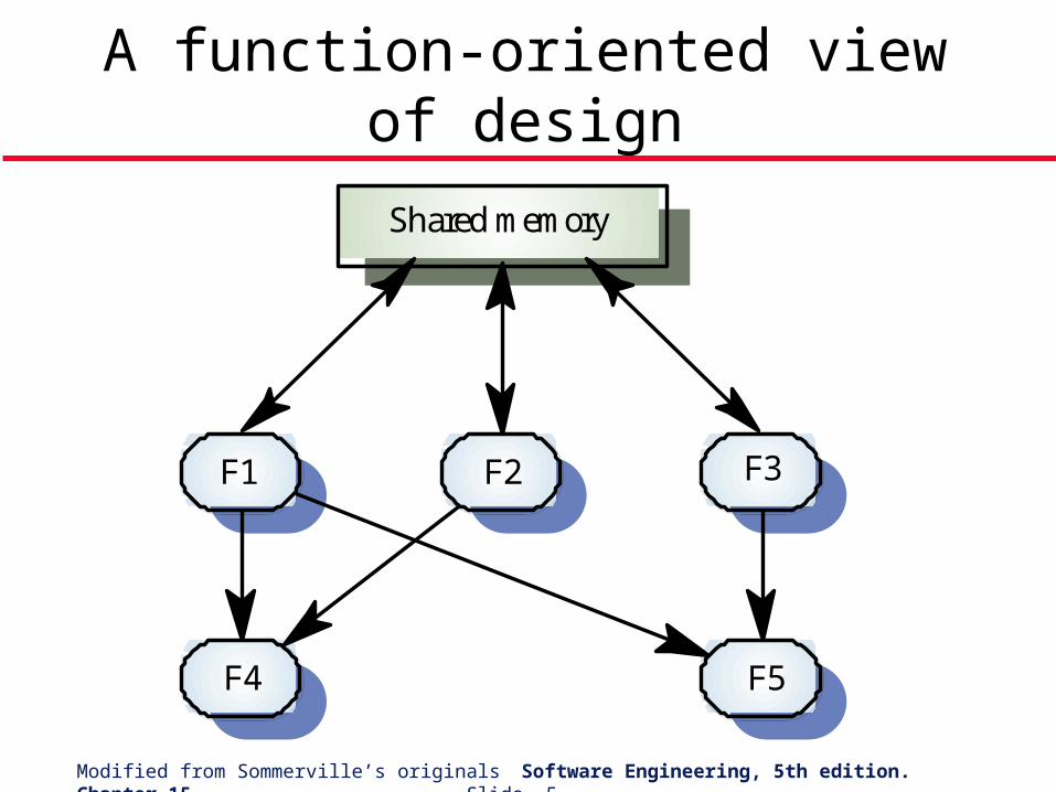
A function-oriented view of design
F2F1 F3
F4 F5
Shared memory
Modified from Sommerville’s originals Software Engineering, 5th edition. Chapter 15 Slide 6
Natural functional systems
Some systems are naturally function-oriented Systems which maintain minimal state
information i.e. where the system is concerned with processing independent actions whose outcomes are not affected by previous actions
Information sharing through parameter lists Transaction processing systems fall into this
category. Each transaction is independent
Modified from Sommerville’s originals Software Engineering, 5th edition. Chapter 15 Slide 7
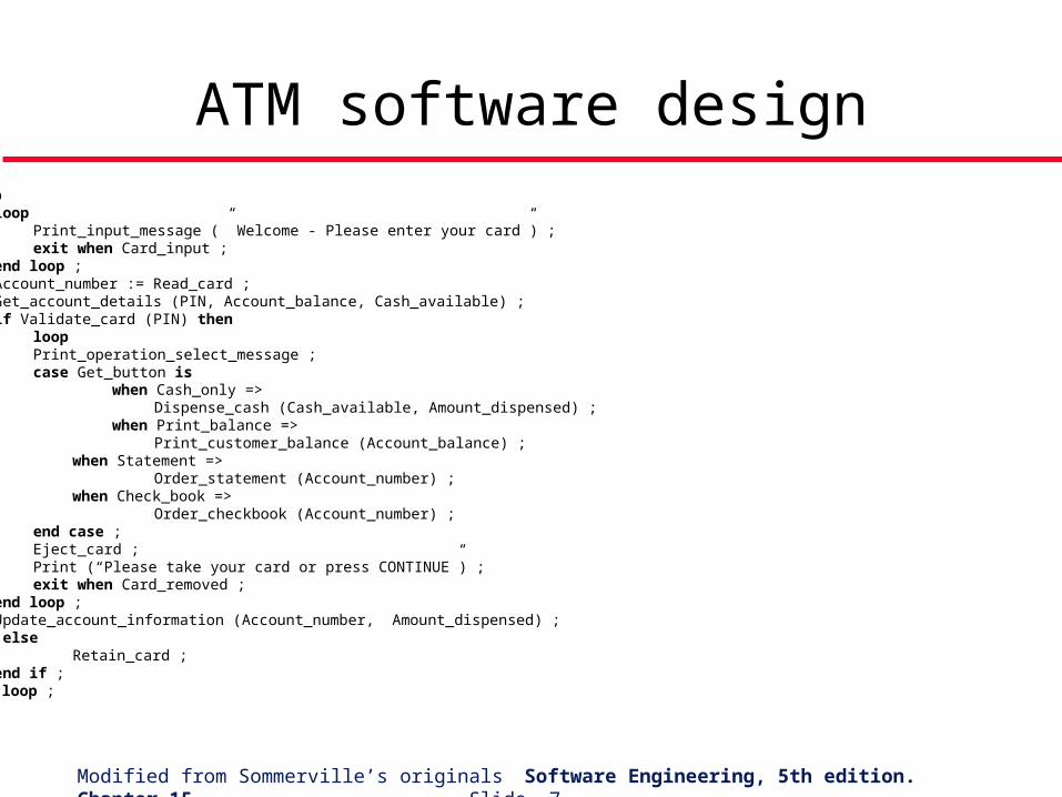
ATM software designloop
loop Print_input_message (” Welcome - Please enter your card”) ; exit when Card_input ; end loop ; Account_number := Read_card ; Get_account_details (PIN, Account_balance, Cash_available) ; if Validate_card (PIN) then loop Print_operation_select_message ; case Get_button is when Cash_only => Dispense_cash (Cash_available, Amount_dispensed) ; when Print_balance => Print_customer_balance (Account_balance) ; when Statement => Order_statement (Account_number) ; when Check_book =>
Order_checkbook (Account_number) ; end case ; Eject_card ; Print (“Please take your card or press CONTINUE”) ; exit when Card_removed ; end loop ; Update_account_information (Account_number, Amount_dispensed) ; else Retain_card ; end if ;end loop ;
Modified from Sommerville’s originals Software Engineering, 5th edition. Chapter 15 Slide 8
Functional and object-oriented design For many types of application, object-oriented
design is likely to lead to a more reliable and maintainable system
Some applications maintain little state – function-oriented design is appropriate
Standards and methods for functional design are well-established
Existing systems must be maintained – function-oriented design will be practised well into the future
Modified from Sommerville’s originals Software Engineering, 5th edition. Chapter 15 Slide 9
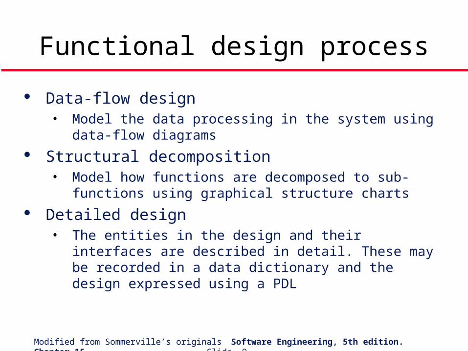
Functional design process
Data-flow design• Model the data processing in the system using data-
flow diagrams Structural decomposition
• Model how functions are decomposed to sub-functions using graphical structure charts
Detailed design• The entities in the design and their interfaces are
described in detail. These may be recorded in a data dictionary and the design expressed using a PDL
Modified from Sommerville’s originals Software Engineering, 5th edition. Chapter 15 Slide 10
Topics covered
Data-flow design Structural decomposition Detailed design A comparison of design strategies
Modified from Sommerville’s originals Software Engineering, 5th edition. Chapter 15 Slide 11
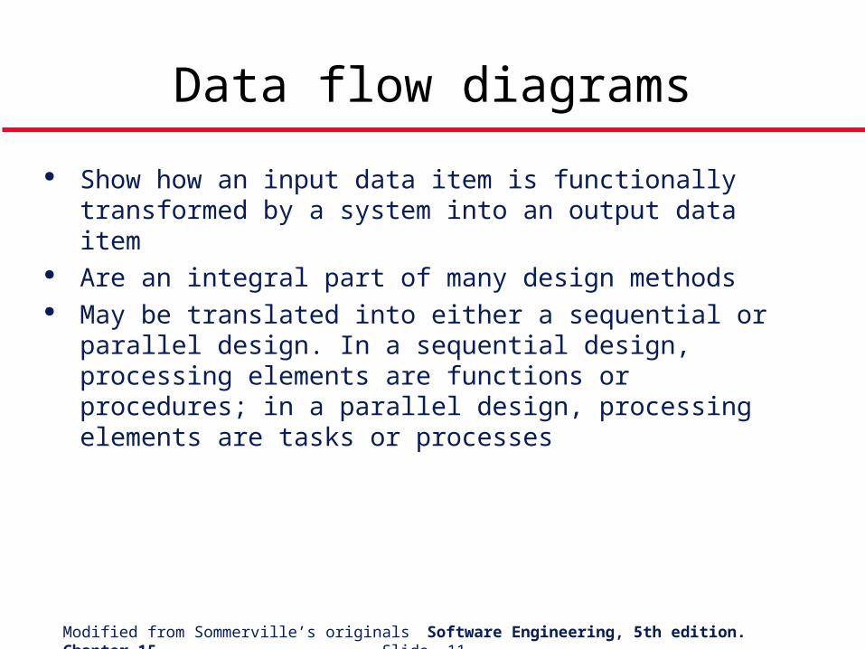
Data flow diagrams
Show how an input data item is functionally transformed by a system into an output data item
Are an integral part of many design methods May be translated into either a sequential or
parallel design. In a sequential design, processing elements are functions or procedures; in a parallel design, processing elements are tasks or processes
Modified from Sommerville’s originals Software Engineering, 5th edition. Chapter 15 Slide 12
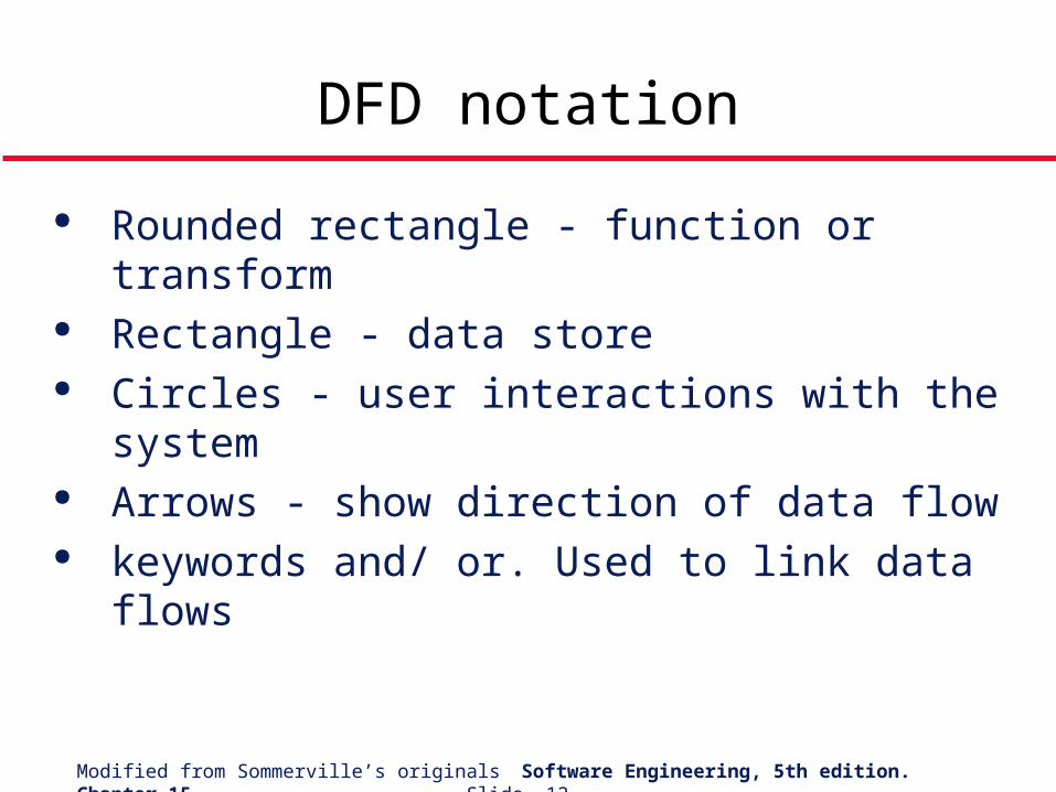
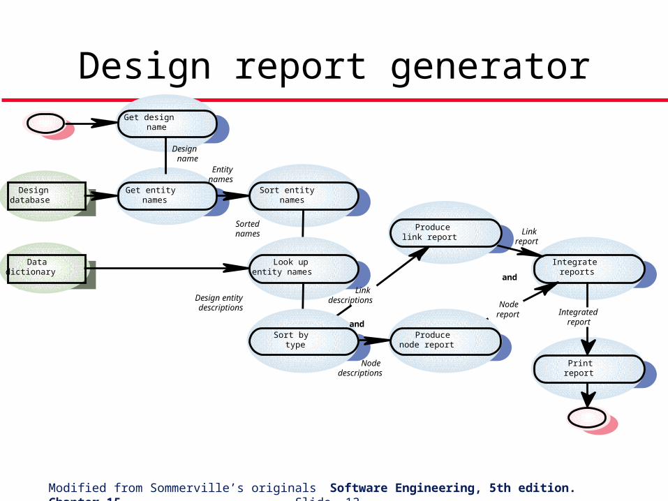
DFD notation
Rounded rectangle - function or transform Rectangle - data store Circles - user interactions with the system Arrows - show direction of data flow keywords and/ or. Used to link data flows
Modified from Sommerville’s originals Software Engineering, 5th edition. Chapter 15 Slide 13
Design report generator
Sort entitynames
Get entitynames
Designdatabase
Get designname
Designname
Look upentity names
Datadictionary
Sort bytype
Entitynames
Sortednames
Design entitydescriptions
Producenode report
Producelink report
Integratereports
Printreport
Linkdescriptions
Nodedescriptions
Integratedreport
Nodereport
Linkreport
and
and
Modified from Sommerville’s originals Software Engineering, 5th edition. Chapter 15 Slide 14
Topics covered
Data-flow design Structural decomposition Detailed design A comparison of design strategies
Modified from Sommerville’s originals Software Engineering, 5th edition. Chapter 15 Slide 15
Structural decomposition is concerned with developing a model of the design which shows the dynamic structure i.e. function calls
This is not necessarily the same as the static composition structure
The aim of the designer should be to derive design units which are highly cohesive and loosely coupled
In essence, a data flow diagram is converted to a structure chart
Structural decomposition
Modified from Sommerville’s originals Software Engineering, 5th edition. Chapter 15 Slide 16
Decomposition guidelines
For business applications, the top-level structure chart may have three functions namely input, process and output
Data validation functions should be subordinate to an input function
Coordination and control should be the responsibility of functions near the top of the hierarchy
Modified from Sommerville’s originals Software Engineering, 5th edition. Chapter 15 Slide 17
Decomposition guidelines
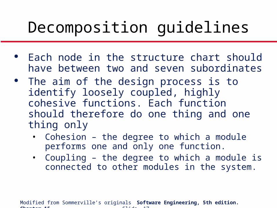
Each node in the structure chart should have between two and seven subordinates
The aim of the design process is to identify loosely coupled, highly cohesive functions. Each function should therefore do one thing and one thing only• Cohesion – the degree to which a module performs
one and only one function.• Coupling – the degree to which a module is
connected to other modules in the system.
Modified from Sommerville’s originals Software Engineering, 5th edition. Chapter 15 Slide 18
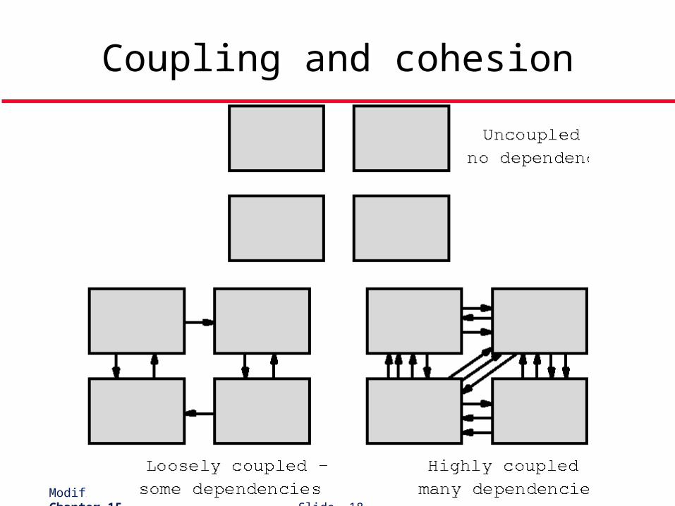
Coupling and cohesion
Modified from Sommerville’s originals Software Engineering, 5th edition. Chapter 15 Slide 19
Process steps
Identify system processing transformations• Transformations in the DFD which are concerned with
processing rather than input/output activities. Group under a single function in the structure chart
Identify input transformations• Transformations concerned with reading, validating and
formatting inputs. Group under the input function Identify output transformations
• Transformations concerned with formatting and writing output. Group under the output function
Modified from Sommerville’s originals Software Engineering, 5th edition. Chapter 15 Slide 20
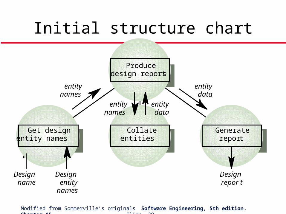
Initial structure chart
Producedesign report s
Collateentities
Gener aterepor t
Get designentity names
Designname
Designentity
names
Designrepor t
entitynames
entitydata
entitydata
entitynames
Modified from Sommerville’s originals Software Engineering, 5th edition. Chapter 15 Slide 21
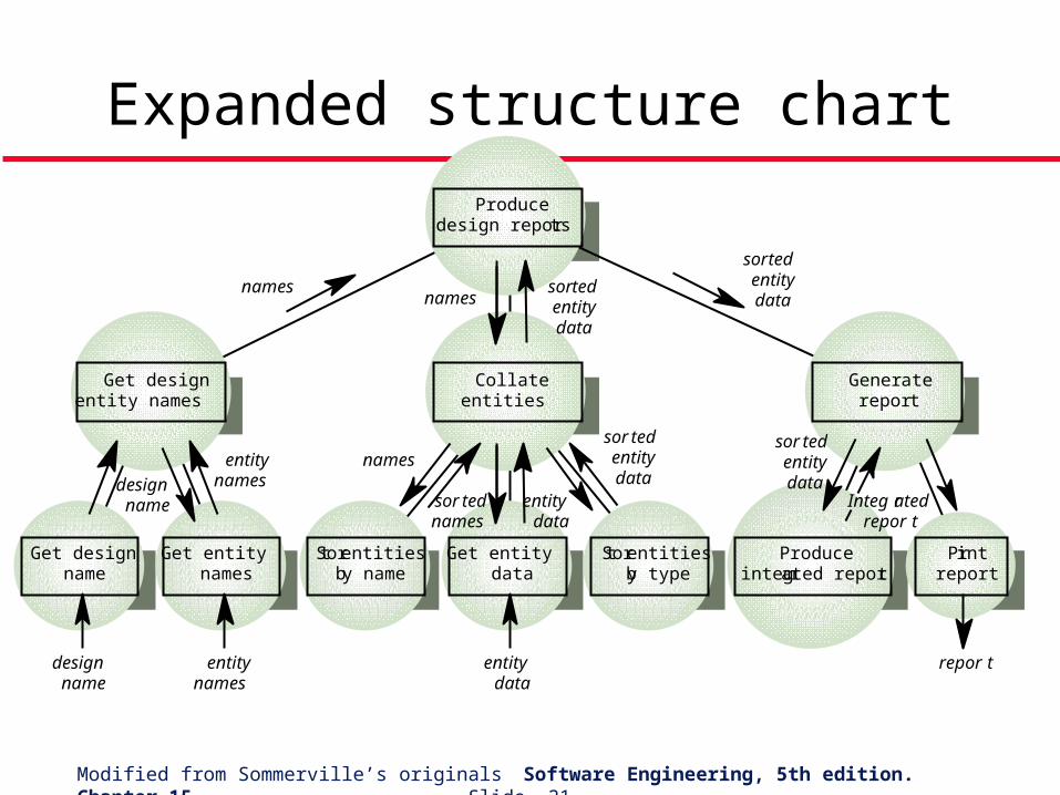
Expanded structure chart
Producedesign repor ts
Collateentities
Gener aterepor t
Get designentity names
entitynames
names
sortedentitydatanames
Get designname
Get entitynames
Sort entitiesby name
Get entitydata
Sort entitiesby type
Produceinteg rated repor t
Printreport
designname
entitynames
repor tentitydata
designname
names
sor tednames
entitydata
sor tedentitydata
sor tedentitydata
Integ ratedrepor t
sortedentitydata
Modified from Sommerville’s originals Software Engineering, 5th edition. Chapter 15 Slide 22
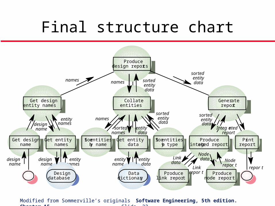
Final structure chart
Datadictionar y
Producedesign repor ts
Collateentities
Generatereport
Get designentity names
entitynames
names
sortedentitydatanames
Get designname
Get entitynames
Sort entitiesby name
Get entitydata
Sort entitiesby type
Produceinteg rated repor t
Printreport
designname
entitynames
repor t
entitydata
designname
names
sortednames
entitydata
sortedentitydata
sortedentitydata
Integ ratedreport
Designdatabase
designname
entityname
Producelink repor t
Producenode repor t
Linkdata
Linkrepor t
Nodedata Node
repor t
sortedentitydata
Modified from Sommerville’s originals Software Engineering, 5th edition. Chapter 15 Slide 23
Topics covered
Data-flow design Structural decomposition Detailed design A comparison of design strategies
Modified from Sommerville’s originals Software Engineering, 5th edition. Chapter 15 Slide 24
Detailed design
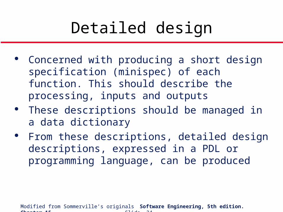
Concerned with producing a short design specification (minispec) of each function. This should describe the processing, inputs and outputs
These descriptions should be managed in a data dictionary
From these descriptions, detailed design descriptions, expressed in a PDL or programming language, can be produced
Modified from Sommerville’s originals Software Engineering, 5th edition. Chapter 15 Slide 25
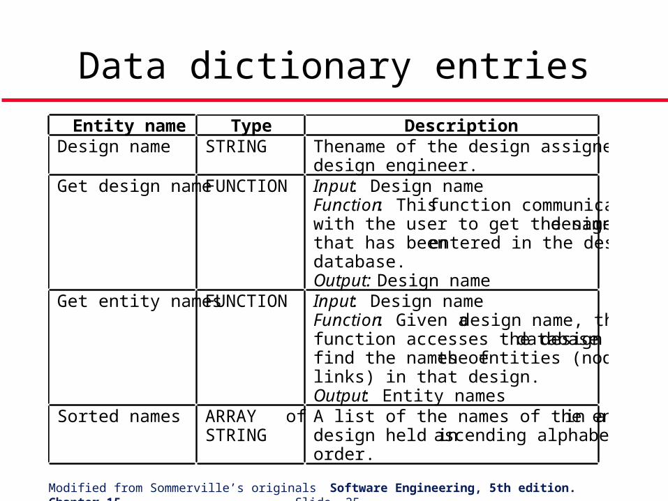
Data dictionary entries
Entity name Type DescriptionDesign name STRING The name of the design assigned by the
design engineer.Get design name FUNCTION Input: Design name
Function: This function communicateswith the user to get the name of a designthat has been entered in the designdatabase.Output: Design name
Get entity names FUNCTION Input: Design nameFunction: Given a design name, thisfunction accesses the design database tofind the names of the entities (nodes andlinks) in that design.Output: Entity names
Sorted names ARRAY ofSTRING
A list of the names of the entities in adesign held in ascending alphabeticalorder.
Modified from Sommerville’s originals Software Engineering, 5th edition. Chapter 15 Slide 26
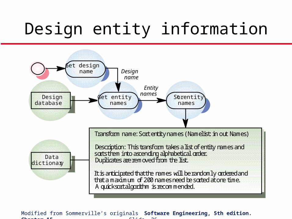
Design entity information
Get entitynames
Designdatabase
Sort entitynames
Transform name: Sort entity names (Namelist: in out Names)
Description: This transform takes a list of entity names andsorts them into ascending alphabetical order.Duplicates are removed from the list.
It is anticipated that the names will be randomly ordered andthat a maximum of 200 names need be sorted at one time.A quicksort algorithm is recommended.
Datadictionar y
Get designname Design
name
Entitynames
Modified from Sommerville’s originals Software Engineering, 5th edition. Chapter 15 Slide 27
Other traditional design practices
Stepwise refinement Structured Systems Analysis and Structured
Design (SSA/SD) Jackson System Development (JSD)
Modified from Sommerville’s originals Software Engineering, 5th edition. Chapter 15 Slide 28
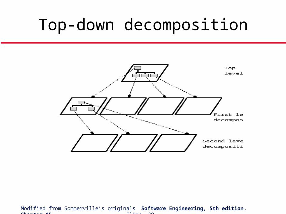
Stepwise refinement
Creator: Niklaus Wirth Historically, this is the first “design method”. A top-down process of successive refinement of specifications. Program construction consists of a sequence of refinement steps,
where a task is divided into subtasks. Strengths:
• Simplicity of the process.• Stepwise nature encourages an orderly development of ideas and also
a means of backtracking. Weaknesses:
• Potential problems with top-down approach which decides on a particular hierarchy early in the project.
• Lack of a stopping rule.• Duplication of lower-level units.
Modified from Sommerville’s originals Software Engineering, 5th edition. Chapter 15 Slide 29
Top-down decomposition
Modified from Sommerville’s originals Software Engineering, 5th edition. Chapter 15 Slide 30
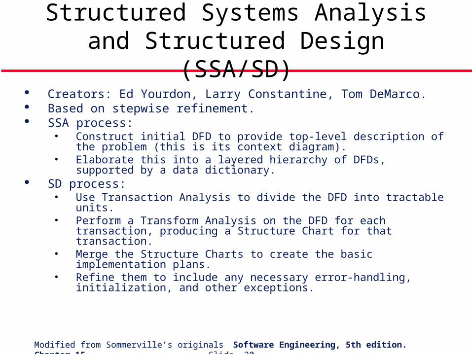
Structured Systems Analysis and Structured Design (SSA/SD)
Creators: Ed Yourdon, Larry Constantine, Tom DeMarco. Based on stepwise refinement. SSA process:
• Construct initial DFD to provide top-level description of the problem (this is its context diagram).
• Elaborate this into a layered hierarchy of DFDs, supported by a data dictionary.
SD process:• Use Transaction Analysis to divide the DFD into tractable units.• Perform a Transform Analysis on the DFD for each transaction,
producing a Structure Chart for that transaction.• Merge the Structure Charts to create the basic implementation plans.• Refine them to include any necessary error-handling, initialization, and
other exceptions.
Modified from Sommerville’s originals Software Engineering, 5th edition. Chapter 15 Slide 31
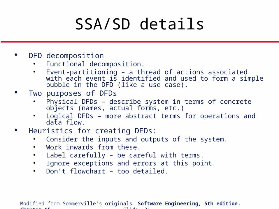
SSA/SD details
DFD decomposition• Functional decomposition.• Event-partitioning – a thread of actions associated with each event is
identified and used to form a simple bubble in the DFD (like a use case).
Two purposes of DFDs• Physical DFDs – describe system in terms of concrete objects
(names, actual forms, etc.)• Logical DFDs – more abstract terms for operations and data flow.
Heuristics for creating DFDs:• Consider the inputs and outputs of the system.• Work inwards from these.• Label carefully – be careful with terms.• Ignore exceptions and errors at this point.• Don’t flowchart – too detailed.
Modified from Sommerville’s originals Software Engineering, 5th edition. Chapter 15 Slide 32
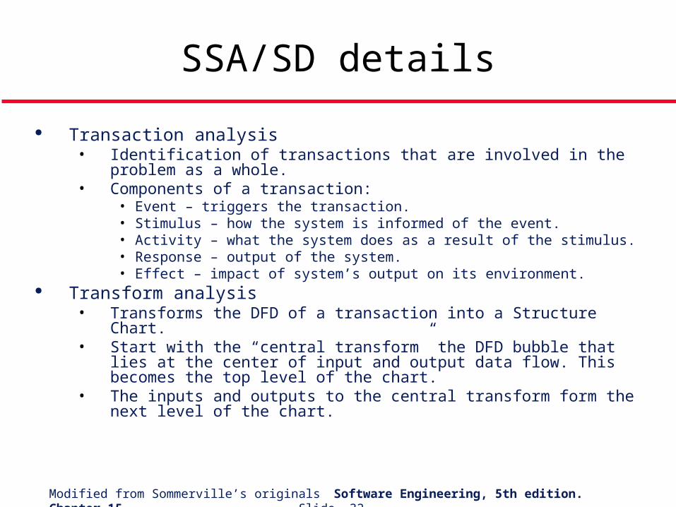
SSA/SD details
Transaction analysis• Identification of transactions that are involved in the problem as a
whole.• Components of a transaction:
• Event – triggers the transaction.• Stimulus – how the system is informed of the event.• Activity – what the system does as a result of the stimulus.• Response – output of the system.• Effect – impact of system’s output on its environment.
Transform analysis• Transforms the DFD of a transaction into a Structure Chart.• Start with the “central transform” the DFD bubble that lies at the center
of input and output data flow. This becomes the top level of the chart.• The inputs and outputs to the central transform form the next level of
the chart.
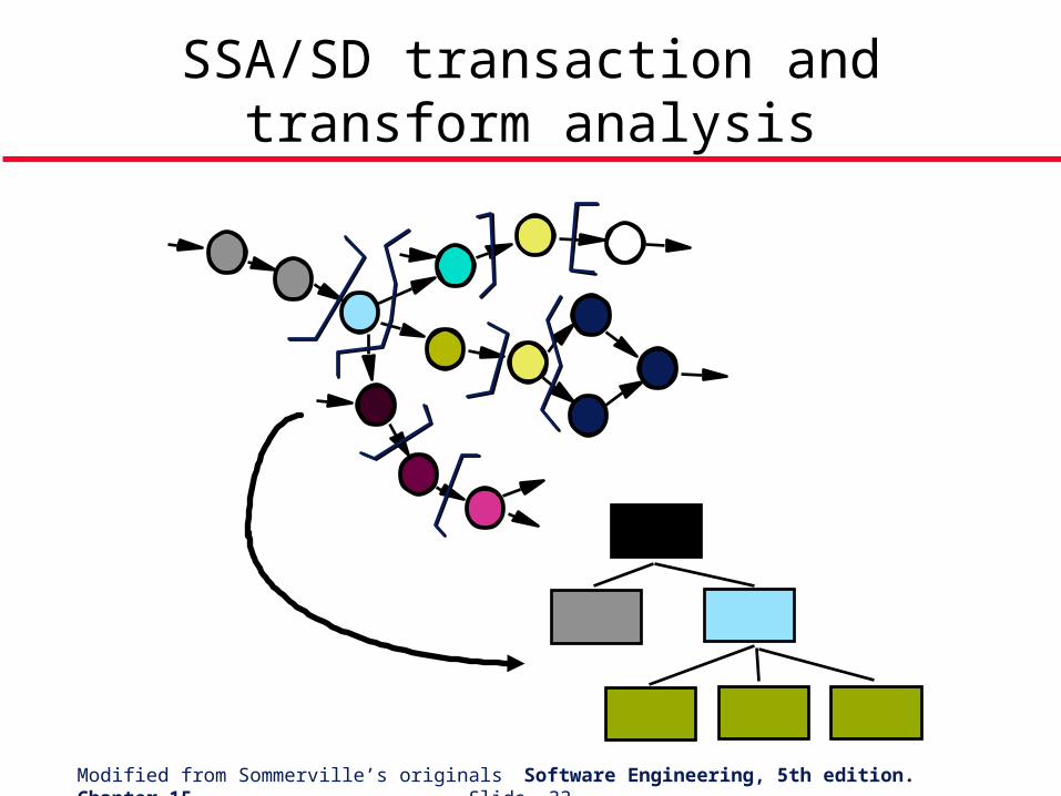
Modified from Sommerville’s originals Software Engineering, 5th edition. Chapter 15 Slide 33
SSA/SD transaction and transform analysis
Modified from Sommerville’s originals Software Engineering, 5th edition. Chapter 15 Slide 34
Jackson System Development (JSD)
Creator: Michael Jackson. Modeling stage – problem is analyzed and modeled in terms of constituent
entities and the actions they perform.• An entity is any object that is important to the system.• Each entity has a set of actions to perform.• Actions take place in the real world at a given point in time.
Network stage – overall structure of the system is developed by adding details of interactions between entities.
• Represented by a system specification diagram (shows processes and how they communicate with each other).
Implementation stage – the abstract design is mapped to a physical design.• Represented by a system implementation diagram • The system is represented as a scheduler that calls modules that implement
the processes.• Datastreams are represented as calls to inverted processes
Modified from Sommerville’s originals Software Engineering, 5th edition. Chapter 15 Slide 35
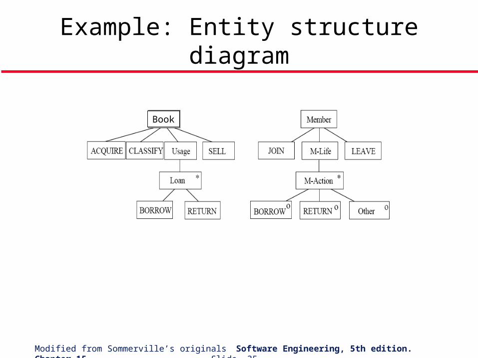
Example: Entity structure diagram
Book
Modified from Sommerville’s originals Software Engineering, 5th edition. Chapter 15 Slide 36
Topics covered
Data-flow design Structural decomposition Detailed design A comparison of design strategies
Modified from Sommerville’s originals Software Engineering, 5th edition. Chapter 15 Slide 37
A comparison of design strategies
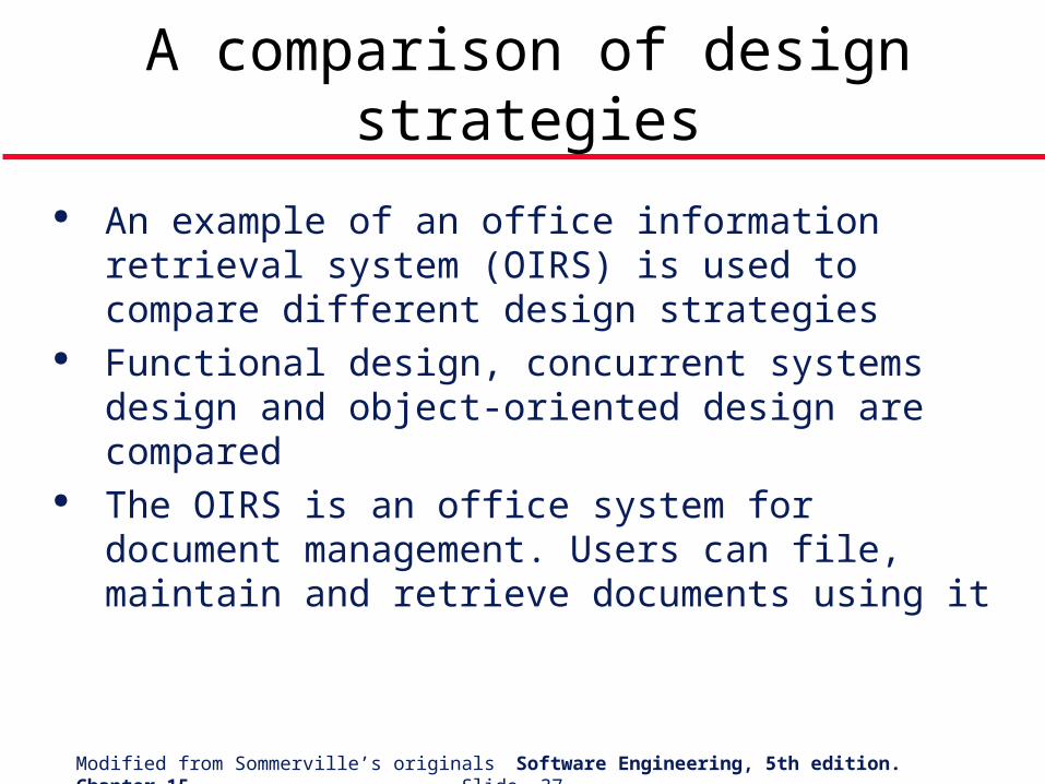
An example of an office information retrieval system (OIRS) is used to compare different design strategies
Functional design, concurrent systems design and object-oriented design are compared
The OIRS is an office system for document management. Users can file, maintain and retrieve documents using it
Modified from Sommerville’s originals Software Engineering, 5th edition. Chapter 15 Slide 38
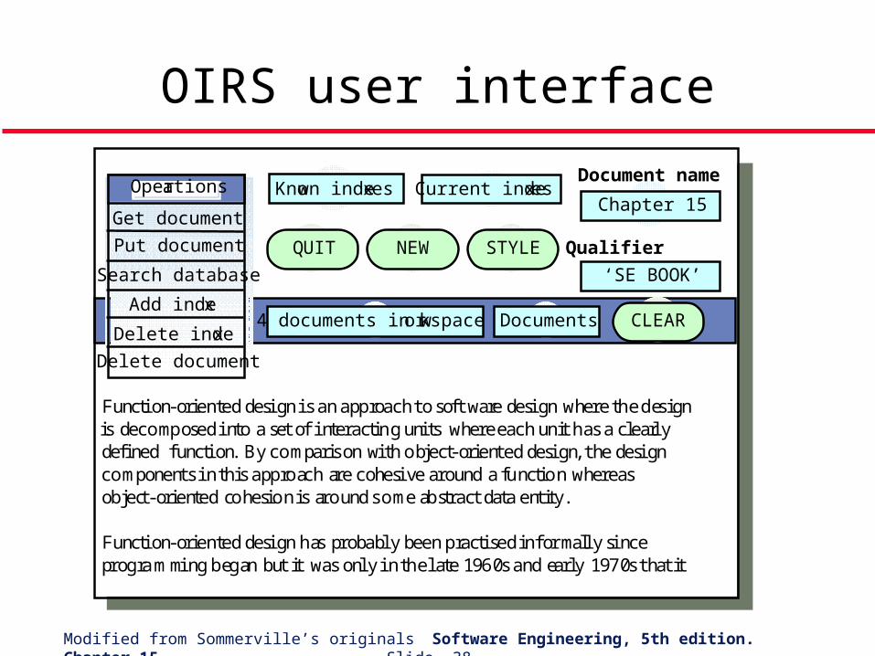
OIRS user interface
Get document
Put document
Search database
Add index
Delete index
Delete document
Known indexes Current indexesChapter 15
‘SE BOOK’
Document name
Documents4 documents in workspace
QUIT
CLEAR
Function-orien ted design is an app roach to software design where the des ignis decomposed into a set of interactin g uni ts where each un it has a clearlydefined function. By comparison with o bject-oriented design, the designcomponents in th is app ro ach are cohesive around a functio n whereasob ject-oriented cohesio n is around some ab stract data ent ity .
Function-orien ted design has probably been p ractised in formally sinceprog ramming beg an but it was only in th e late 1960s and early 197 0s that it
Operations
NEW STYLE Qualifier
Modified from Sommerville’s originals Software Engineering, 5th edition. Chapter 15 Slide 39
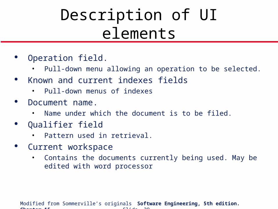
Description of UI elements
Operation field. • Pull-down menu allowing an operation to be selected.
Known and current indexes fields• Pull-down menus of indexes
Document name.• Name under which the document is to be filed.
Qualifier field• Pattern used in retrieval.
Current workspace• Contains the documents currently being used. May be edited with
word processor
Modified from Sommerville’s originals Software Engineering, 5th edition. Chapter 15 Slide 40
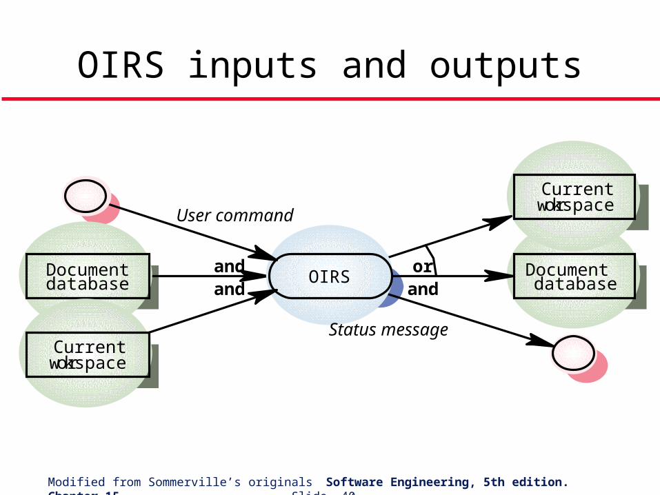
OIRS inputs and outputs
OIRSDocumentdatabase
Documentdatabase
Currentworkspace
Currentworkspace
User command
Status message
andand
orand
Modified from Sommerville’s originals Software Engineering, 5th edition. Chapter 15 Slide 41
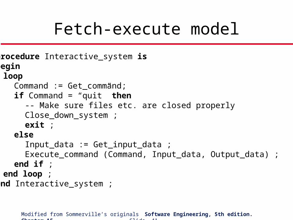
Fetch-execute model
procedure Interactive_system isbegin
loopCommand := Get_command;if Command = “quit” then
-- Make sure files etc. are closed properlyClose_down_system ;exit ;
elseInput_data := Get_input_data ;Execute_command (Command, Input_data, Output_data) ;
end if ;end loop ;
end Interactive_system ;
Modified from Sommerville’s originals Software Engineering, 5th edition. Chapter 15 Slide 42
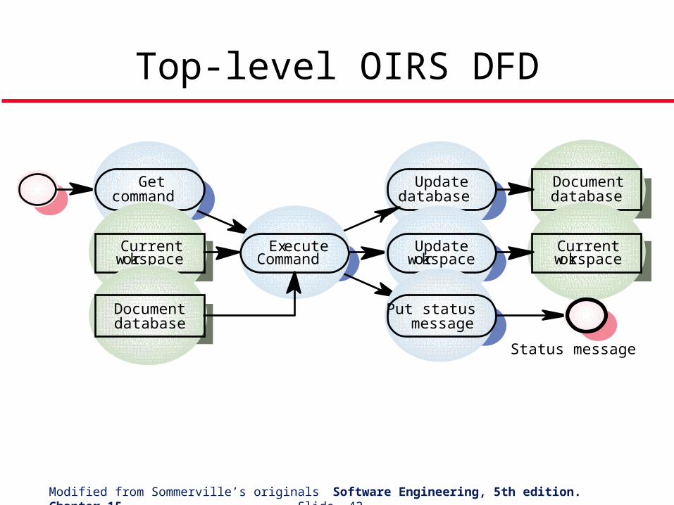
Top-level OIRS DFD
Getcommand
Updatedatabase
Documentdatabase
Currentworkspace
ExecuteCommand
Updateworkspace
Currentworkspace
Documentdatabase
Put statusmessage
Status message
Modified from Sommerville’s originals Software Engineering, 5th edition. Chapter 15 Slide 43
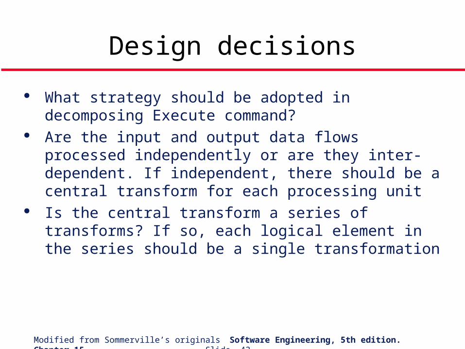
What strategy should be adopted in decomposing Execute command?
Are the input and output data flows processed independently or are they inter-dependent. If independent, there should be a central transform for each processing unit
Is the central transform a series of transforms? If so, each logical element in the series should be a single transformation
Design decisions
Modified from Sommerville’s originals Software Engineering, 5th edition. Chapter 15 Slide 44
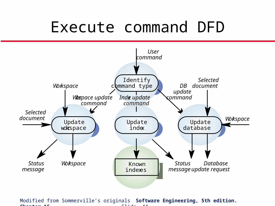
Execute command DFD
Identifycommand type
Updateindex
Updatedatabase
Updateworkspace
Knowninde xes
Usercommand
Index updatecommand
Workspace updatecommand
Workspace
Selecteddocument
Statusmessage
Workspace Statusmessage
Databaseupdate request
Workspace
SelecteddocumentDB
updatecommand
Modified from Sommerville’s originals Software Engineering, 5th edition. Chapter 15 Slide 45
OIRS design
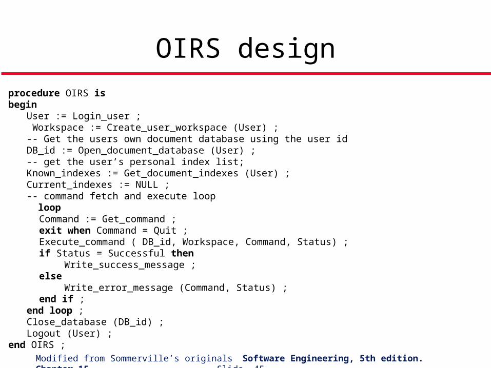
procedure OIRS isbegin User := Login_user ; Workspace := Create_user_workspace (User) ;
-- Get the users own document database using the user id DB_id := Open_document_database (User) ;
-- get the user’s personal index list;Known_indexes := Get_document_indexes (User) ;Current_indexes := NULL ;-- command fetch and execute loop loop
Command := Get_command ;exit when Command = Quit ;Execute_command ( DB_id, Workspace, Command, Status) ;if Status = Successful then
Write_success_message ;else
Write_error_message (Command, Status) ;end if ;
end loop ;Close_database (DB_id) ;Logout (User) ;
end OIRS ;
Modified from Sommerville’s originals Software Engineering, 5th edition. Chapter 15 Slide 46
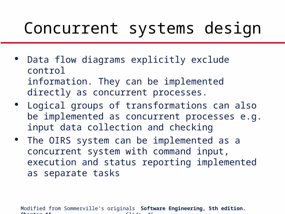
Data flow diagrams explicitly exclude control information. They can be implemented directly as concurrent processes.
Logical groups of transformations can also be implemented as concurrent processes e.g. input data collection and checking
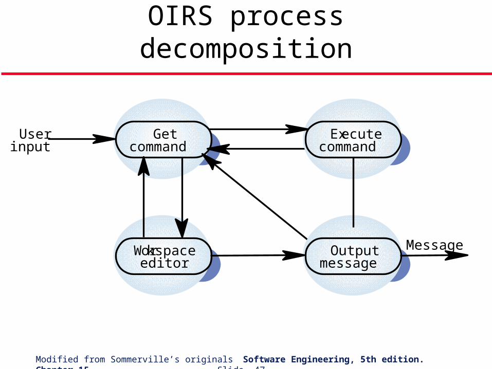
The OIRS system can be implemented as a concurrent system with command input, execution and status reporting implemented as separate tasks
Concurrent systems design
Modified from Sommerville’s originals Software Engineering, 5th edition. Chapter 15 Slide 47
OIRS process decomposition
Executecommand
Getcommand
Outputmessage
Workspaceeditor
Userinput
Message
Modified from Sommerville’s originals Software Engineering, 5th edition. Chapter 15 Slide 48
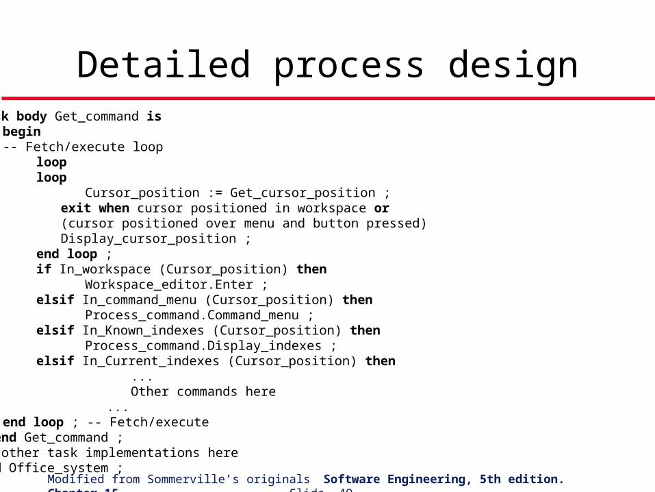
Detailed process design
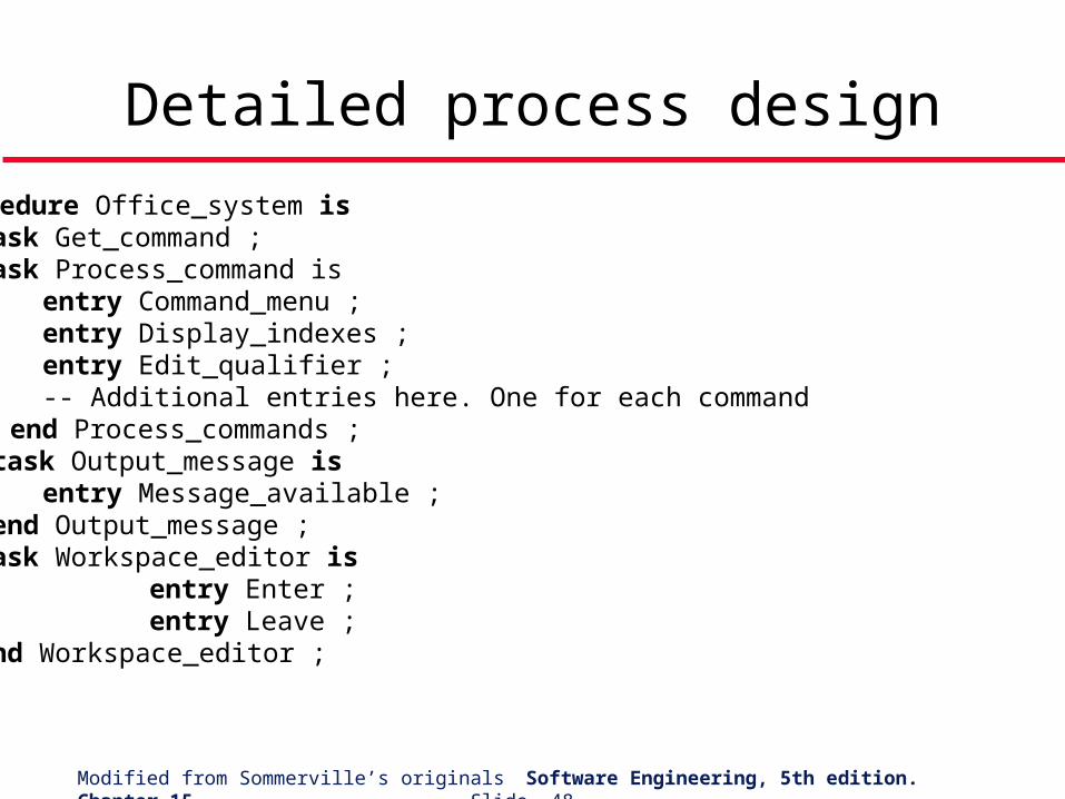
procedure Office_system istask Get_command ;
task Process_command is entry Command_menu ; entry Display_indexes ; entry Edit_qualifier ; -- Additional entries here. One for each command end Process_commands ; task Output_message is entry Message_available ; end Output_message ; task Workspace_editor is entry Enter ; entry Leave ; end Workspace_editor ;
Modified from Sommerville’s originals Software Engineering, 5th edition. Chapter 15 Slide 49
Detailed process designtask body Get_command is begin
-- Fetch/execute loop loop loop Cursor_position := Get_cursor_position ; exit when cursor positioned in workspace or (cursor positioned over menu and button pressed) Display_cursor_position ; end loop ; if In_workspace (Cursor_position) then Workspace_editor.Enter ; elsif In_command_menu (Cursor_position) then Process_command.Command_menu ; elsif In_Known_indexes (Cursor_position) then Process_command.Display_indexes ; elsif In_Current_indexes (Cursor_position) then
... Other commands here
...end loop ; -- Fetch/execute
end Get_command ;-- other task implementations hereend Office_system ;
Modified from Sommerville’s originals Software Engineering, 5th edition. Chapter 15 Slide 50
Object-oriented design
An object-oriented design focuses on the entities in the system rather than the data processing activities
Simplified OOD here which illustrates a different decomposition
Modified from Sommerville’s originals Software Engineering, 5th edition. Chapter 15 Slide 51
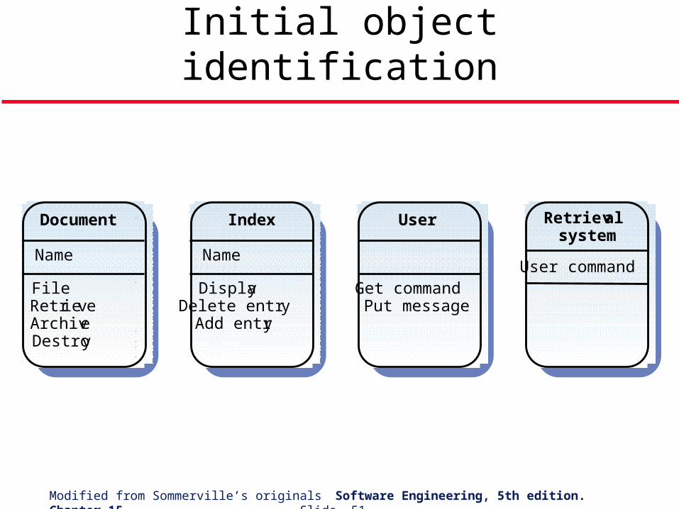
Initial object identification
FileRetrieveArchiveDestroy
Document
Name
DisplayDelete entr y
Add entry
Inde x
Name
Get commandPut message
User Retrie valsystem
User command
Modified from Sommerville’s originals Software Engineering, 5th edition. Chapter 15 Slide 52
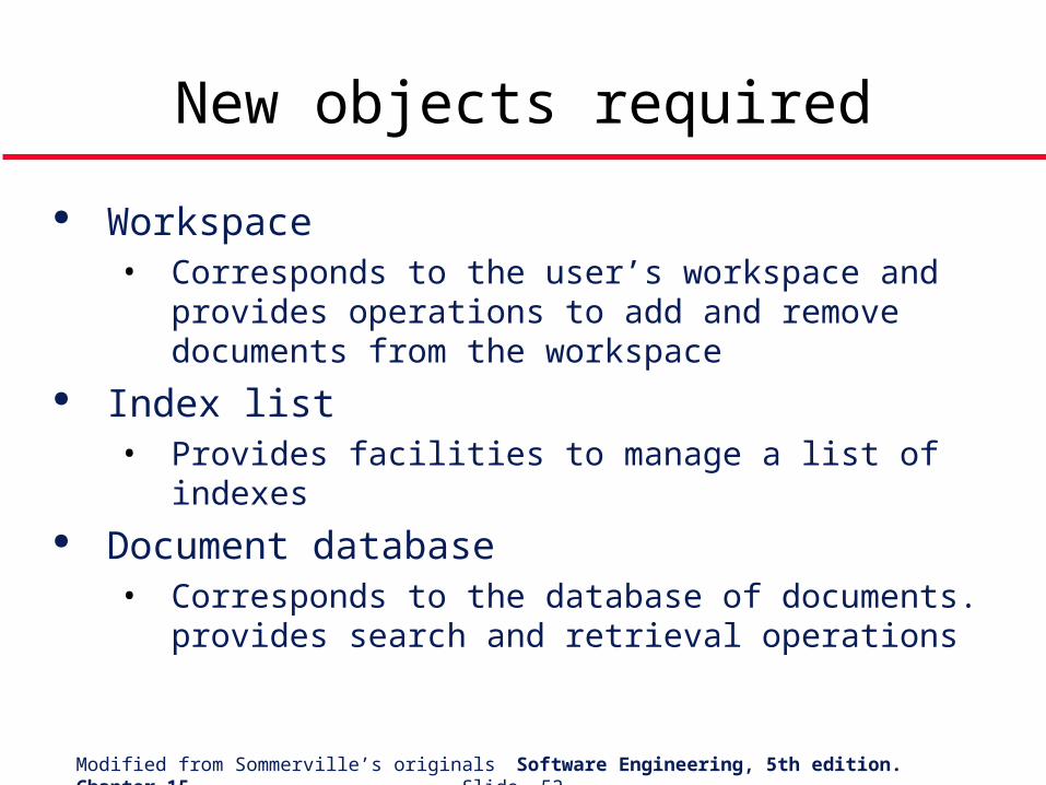
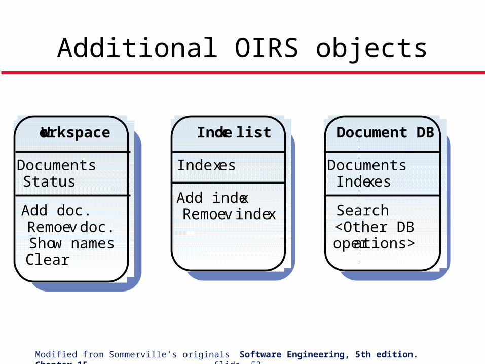
New objects required
Workspace• Corresponds to the user’s workspace and provides
operations to add and remove documents from the workspace
Index list• Provides facilities to manage a list of indexes
Document database• Corresponds to the database of documents.
provides search and retrieval operations
Modified from Sommerville’s originals Software Engineering, 5th edition. Chapter 15 Slide 53
Additional OIRS objects
Add doc.Remo ve doc.Show namesClear
Workspace
DocumentsStatus
Add indexRemo ve inde x
Index list
Inde xes
Search<Other DBoperations>
Document DB
DocumentsIndexes
Modified from Sommerville’s originals Software Engineering, 5th edition. Chapter 15 Slide 54
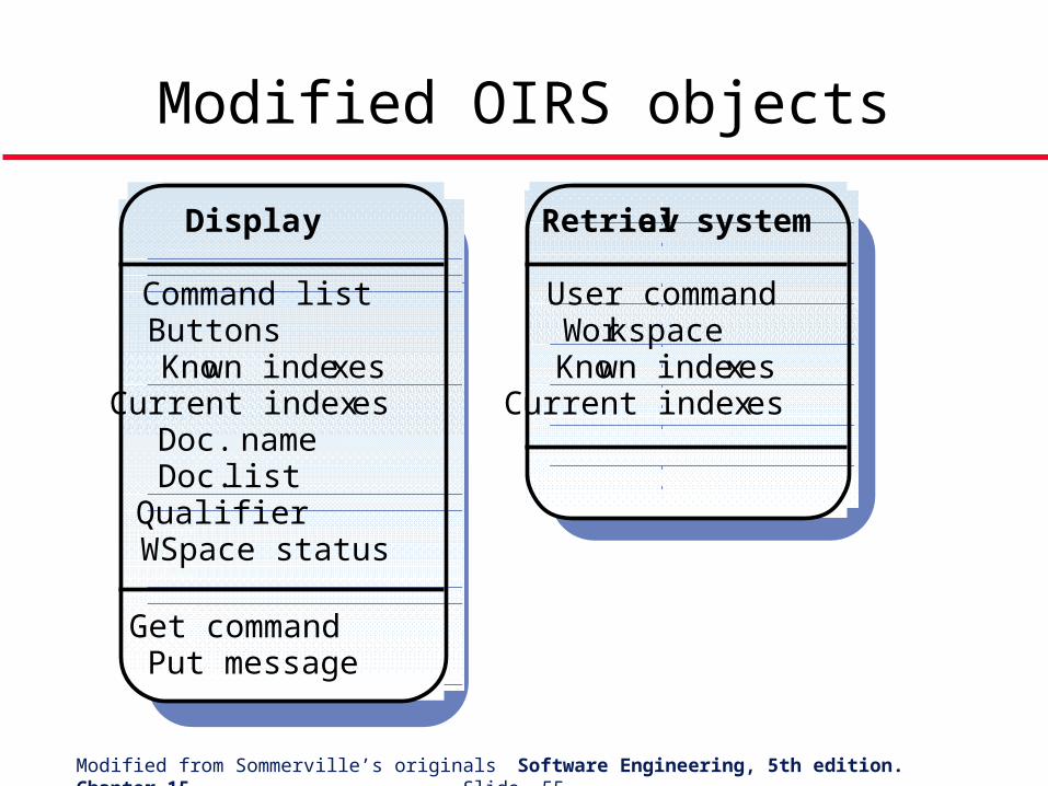
Object refinement
Retrieval system does not provide services. It coordinates other objects. It has only attributes
Documents and indexes are explicitly named The individual command components have
been bundled into a single attribute User command in Retrieval system
The User object has been replaced by the Display object
Modified from Sommerville’s originals Software Engineering, 5th edition. Chapter 15 Slide 55
Modified OIRS objects
Get commandPut message
Displa y
Command listButtonsKnown inde xes
Current inde xesDoc. nameDoc. listQualifierWSpace status
Retrie val system
User commandWorkspaceKnown inde xes
Current inde xes
Modified from Sommerville’s originals Software Engineering, 5th edition. Chapter 15 Slide 56
Function-oriented design relies on identifying functions which transform inputs to outputs
Many business systems are transaction processing systems which are naturally functional
The functional design process involves identifying data transformations, decomposing functions into sub-functions and describing these in detail
Key points
Modified from Sommerville’s originals Software Engineering, 5th edition. Chapter 15 Slide 57
Key points
Data-flow diagrams are a means of documenting end-to-end data flow. Structure charts represent the dynamic hierarchy of function calls
Data flow diagrams can be implemented directly as cooperating sequential processes
Functional and object-oriented design result in different system decompositions. However, a heterogeous approach to design is often necessary