Embed Size (px)
Citation preview
Reference ArchitectureData Center | Hybrid Cloud
Executive SummaryA modern data center is key to remaining competitive. All companies must overcome challenges to accelerate product development; reduce downtime and maintenance overhead; and compete more successfully at lower cost. Technology is now a centerpiece of every new change; the traditional approach for hosting applications and services cannot deliver innovation at the pace businesses require.
For companies with outdated data center technologies, meeting these challenges involves replacing legacy hardware and software with modern, hybrid-cloud-capable solutions that can accelerate the entire software and hardware provisioning, deployment, and maintenance lifecycle along with application development, testing, and delivery. End-user self-service solutions are expected to reduce the time to market even more. VMware Cloud Foundation and Intel address these new market requirements by offering an easily deployable and manageable hybrid/multicloud platform for managing virtual machines (VMs) and orchestrating containers. This solution provides infrastructure and operations across private and public clouds with excellent performance and reliability from Intel® hardware components.
This reference architecture describes the following:
• How to prepare and deploy a VMware Cloud Foundation 4.0 environment connected to VMware Cloud on Amazon Web Services (AWS).
• How to take advantage of relevant Intel® technology such as Intel® Optane™ persistent memory and Intel® Deep Learning Boost (Intel® DL Boost).
Because the term “cloud computing” is now often associated with both VMs and the use of containerization, this reference architecture illustrates a variety of applications. These include VM-based solutions, as well as container-based analytics and artificial intelligence (AI) workloads. These use cases highlight the flexibility of the solution and overall performance.
The intended audience for this reference architecture includes system administrators and system architects. Some experience with virtualization technology, networking (VMware NSX-T Data Center), and Kubernetes is assumed, as is an understanding of machine learning and AI core concepts.
Accelerate workload deployment, simplify management, and boost your competitive edge by combining Intel® technology, VMware hybrid cloud software, and VMware Cloud on AWS
Modernize the Data Center for Hybrid Cloud
Intel Data Platform Group AuthorsPatryk Wolsza vExpert, Cloud Solutions Architect
Karol Brejna Senior Architect
Marcin Hoffmann Cloud Solutions Engineer
Lukasz Sitkiewicz Software Engineer
ContributorsMarek Malczak Cloud Solutions Engineer
Ewelina Kamyszek Tech. Undergrad Intern
Marcin Gajzler Cloud Solutions Engineer
Piotr Grabuszynski Software Engineer
VMware AuthorsRick Walsworth VMware Cloud Sr. Product Line Marketing Manager
Enrique Corro Data Science Staff Engineer, Office of the CTO
Christopher Martin Cloud Solutions Engineer, VMware Cloud

Reference Architecture | Modernize the Data Center for Hybrid Cloud 2
Introduction: Why VMware Cloud Foundation for Your Hybrid/Multicloud?A hybrid/multicloud infrastructure combines the benefits of an on-premises infrastructure with the flexibility and instant availability of one or more public clouds. This approach is gaining popularity as businesses adapt their existing computing resources to ever-changing demands and market needs. While there are many examples of services that are ideal for the public cloud, some workloads are better suited to staying on-premises (such as sensitive data that is required for machine-learning models). Increasingly, enterprises want a hybrid/multicloud option for this flexibility and business agility (see Figure 1). Hybrid and multicloud solutions are especially important as AI and machine-learning workloads become increasingly prevalent.
With the end-to-end solution that Intel and VMware offer, enterprises can quickly launch database processing and AI, and scale workloads to accommodate future needs. The unified cloud solution presented in this reference architecture (see Figure 2 on the next page) can run containerized applications and traditional VMs, located in an on-premises data center as well as in the public cloud, such as on AWS. The hybrid/multicloud nature of the solution allows enterprises to extend available resources and easily migrate workloads from on-premises to the cloud and back.
VMware Cloud Foundation
PrivateCloud
PublicCloud
VMware SDDC Manager
VMwareNSX-T
VMwarevRealize Suite
VMwarevSAN
VMwarevSphere
Figure 1. VMware Cloud Foundation is a cloud solution that is managed through VMware SDDC Manager and built on VMware vSphere, vRealize Suite, vSAN, and NSX-T Data Center.
Table of ContentsExecutive Summary . . . . . . . . . . . . . . . . . . . . . . . . . . . . . . . . . 1
Introduction: Why VMware Cloud Foundation for Your Hybrid/Multicloud? . . . . . . . . . . . . . . . . . . . . . . . . . . . . . 2
Solution Overview . . . . . . . . . . . . . . . . . . . . . . . . . . . . . . . . . . . 3Hardware Overview . . . . . . . . . . . . . . . . . . . . . . . . . . . . . . . . . . . .3Software Overview . . . . . . . . . . . . . . . . . . . . . . . . . . . . . . . . . . . .3
Technology Descriptions . . . . . . . . . . . . . . . . . . . . . . . . . . . . . 3Intel Hardware . . . . . . . . . . . . . . . . . . . . . . . . . . . . . . . . . . . . . . . . .4Cloud Infrastructure . . . . . . . . . . . . . . . . . . . . . . . . . . . . . . . . . . .6Data Warehousing Building Blocks . . . . . . . . . . . . . . . . . . . . .8Analytics and AI Building Blocks . . . . . . . . . . . . . . . . . . . . . . .8Self-Service Application Catalogs . . . . . . . . . . . . . . . . . . . . . .9
Platform-Verified Analytics/AI Workload Performance 10Deep-Learning Inference . . . . . . . . . . . . . . . . . . . . . . . . . . . . 10Machine-Learning Model Training . . . . . . . . . . . . . . . . . . . . 11Build Once, Run Anywhere . . . . . . . . . . . . . . . . . . . . . . . . . . 12
Bill of Materials . . . . . . . . . . . . . . . . . . . . . . . . . . . . . . . . . . . .12Hardware . . . . . . . . . . . . . . . . . . . . . . . . . . . . . . . . . . . . . . . . . . . . 12Software . . . . . . . . . . . . . . . . . . . . . . . . . . . . . . . . . . . . . . . . . . . . 12BIOS and Firmware Components . . . . . . . . . . . . . . . . . . . . . 12
Deployment Blocks . . . . . . . . . . . . . . . . . . . . . . . . . . . . . . . . .14VMware Cloud Foundation . . . . . . . . . . . . . . . . . . . . . . . . . . . 14VMware vSAN . . . . . . . . . . . . . . . . . . . . . . . . . . . . . . . . . . . . . . . 14VMware NSX-T Data Center . . . . . . . . . . . . . . . . . . . . . . . . . . 15vSphere with Tanzu . . . . . . . . . . . . . . . . . . . . . . . . . . . . . . . . . 15Tanzu Kubernetes Clusters . . . . . . . . . . . . . . . . . . . . . . . . . . . 16VMware Cloud on AWS . . . . . . . . . . . . . . . . . . . . . . . . . . . . . . 18
Environment Configuration and Deployment . . . . . . . . .19Installation and Configuration of Intel Optane Persistent Memory Modules on VMware ESXi . . . . . . . . . . . . . . . . . . . 19Preparing a VM for Intel Optane Persistent Memory . . 19
Environment Provisioning . . . . . . . . . . . . . . . . . . . . . . . . . .19Hardware and Software Requirements . . . . . . . . . . . . . . . 19Initiate the VMware Cloud Foundation Bring-Up . . . . . 20VMware Cloud Foundation Workload Domain Deployment . . . . . . . . . . . . . . . . . . . . . . . . . . . . . . . . . 21VMware Cloud on AWS Configuration . . . . . . . . . . . . . . . . 23
Summary . . . . . . . . . . . . . . . . . . . . . . . . . . . . . . . . . . . . . . . . . .23
Appendix A: Solution Features Validation and Benchmarking . . . . . . . . . . . . . . . . . . . . . . . . . . . . . . . . . . . . . .25

Reference Architecture | Modernize the Data Center for Hybrid Cloud 3
Analytics/AI
Cloud Infrastructure: VMware Cloud Foundation 4.0
Intel Data Center Blocks For Cloud – VMware (vSAN ReadyNodes)
VMware vSphere ClusterVMware NSX-T Data Center
VMware vRealize Suite
VMware vCenter Server
VMware vSAN VMware ESXi Hypervisor
Intel® Architecture Optimized Building Blocks
Intel® Distribution for Python
Intel® Architecture-Optimized Containers Intel® MKL
Intel® MKL-DNN
Tanzu Kubernetes Grid (TKG) Services
VMware Software-DefinedData Center Manager
Intel® SSDDC P4510 Series
NVMe-Based3D NAND
Intel® Ethernet700 Series
2nd Gen Intel® Xeon®Scalable Processors
Gold 6230-6248
Platinum 8268
Consistent High-Performance Architecture Based on Intel® Technology
Machine-LearningFramework
DataRobot NoSQLDatabases
SQLDatabases
Data Warehousing
VMware Cloudon AWS
VMware vSphere Cluster
VMware NSX-T Data Center
VMware vSphere w/ Kubernetes
VMware vSAN
VMware vRealize Suite
VMware vCenter
VMware vSphere
VMware Software-DefinedData Center Manager
HCX
VPN
Hybrid LinkMode
VMwareCloud Block
Spanning
SSD DC P4800XSeries
Bare MetalInfrastructure
i3.metal
i3en.metal
Amazon EC2Bare-Metal Instances
Figure 2. Reference architecture building blocks for the VMware hybrid/multicloud platform.
Solution OverviewThis reference architecture provides detailed configuration information for building a hybrid/multicloud. At a high level, the reference architecture consists of an optimized combination of Intel® hardware and VMware software.
Hardware OverviewThe hardware stack for the solution is built on Intel® Server Board S2600WF0R platforms. The platforms include the latest generation of Intel® Xeon® Gold processors and Intel® Xeon® Platinum processors. These processors support Intel® Deep Learning Boost (Intel® DL Boost), which uses Vector Neural Network Instructions (VNNI) to boost AI inferencing performance. For high-performance, all-flash software-defined storage, the reference architecture includes Intel® Optane™ SSD DC P4800X and NVMe-based Intel® SSD DC P4510 combined with Intel® Optane™ persistent memory (PMem). Intel Optane PMem introduces innovative memory technology that delivers large-capacity system memory and persistence. For an accelerated software-defined network, the platforms use 25 Gb/s Intel® Ethernet Converged Network Adapters X710-DA2.
Software OverviewFrom a software perspective, the solution consists of VMware Cloud Foundation 4.0.1, which is based on several main VMware components: VMware vSphere with Tanzu (formerly called vSphere with Kubernetes), VMware Tanzu Kubernetes Grid (TKG) Service for vSphere, VMware vSAN, VMware vRealize Suite, VMware NSX-T Data Center, and VMware SDDC Manager to provide IaaS capabilities.
VMware Cloud on AWS is used as the destination for the hybrid architecture. VMware Hybrid Cloud Extension (HCX) enables VM migration, workload rebalancing, and protection between on-premises and cloud.1 In addition to business continuity, it provides network extension for multi-tier applications without changing the VM properties.
Technology DescriptionsThis section describes the building blocks in each of the reference architecture’s layers: hardware, cloud infrastructure, database building blocks, and analytics/AI building blocks. The platform benefits from Intel® Optane™ technology used throughout the entire stack, as shown in Figure 3.
VMware vSphere VMware vSANVMware vSphere VMware vSAN
VM VM VM
Compute
Storage
MEMORYIntel® Optane™ Persistent Memory
(Expanded Memory)
CACHE TIERIntel® Optane™ SSD
(Storage Cache)
CAPACITY TIERIntel® 3D NAND SSD(Storage Capacity)
WRITE READ
Figure 3. The placement of Intel® Optane™ SSDs and Intel® Optane™ persistent memory within the architecture. Source: principledtechnologies.com/VMware/VMware-HCI-Intel-Optane-VDI-0420.pdf

Reference Architecture | Modernize the Data Center for Hybrid Cloud 4
Intel HardwareIntel Optane Persistent MemoryIntel Optane PMem represents a new class of memory and storage technology. It is designed to improve the overall performance of the server by providing large amounts of persistent storage with low-latency access. Intel Optane PMem modules are DDR4-socket compatible and are offered in sizes not available with typical DDR4 DRAM products: 128, 256, and 512 GB per module. The default Base configuration does not use PMem. However, the Base configuration can be upgraded to use PMem modules without any additional hardware changes to take advantage of PMem benefits.
Intel Optane PMem can work in two different operating modes (Memory Mode and App Direct Mode), depending on business need and/or application support, as shown in Figure 4. Regardless of the mode used, PMem provides capacity that is unavailable when using traditional DRAM modules. Operating modes can be configured using the platform BIOS or memory management tools. App Direct-Dual Mode is also possible by partitioning the memory pool. For additional information and guidelines, visit the Intel Optane persistent memory Quick Start Guide.
Memory Mode(Legacy Workloads)
Affordable Memory Capacityfor Many Applications
App Direct Mode(Optimized Workloads)
Volatile and Persistent Usage Modelsfor Maximum Capacity
VOLATILE MEMORY POOL
DRAM as Cache Intel® Optane™Persistent Memory
APPLICATION
DRAMIntel OptanePersistent Memory
APPLICATION
Figure 4. Intel® Optane™ persistent memory operating modes. Source: servethehome.com/2nd-gen-intel-xeon-scalable-launch-cascade-lake-details-and-analysis/intel-optane-dcpmm-memory-and-app-direct-modes
Memory Mode for Expansion of Regular DDR4 DRAMThis mode is ideal to expand the capacity of memory available to support more or larger VMs in virtual desktop infrastructure (VDI) deployments. This mode can also support higher quantities of “hot” data available for processing with in-memory databases, analytics, and other demanding workloads. It allows organizations to maintain larger amounts of data closer to the processor, with consistent, near-DRAM performance. In this mode, the PMem is visible to all applications (including the OS) as volatile memory, just as if it was regular DRAM. Its content is lost when the system is powered off. At the hardware level, there is a combination of PMem modules and standard DRAM; the DRAM acts as a cache for most frequently accessed data, and the PMem provides capacity. Typically, the DRAM-to-PMem ratio ranges from 1:4 to 1:8. Only the PMem module’s size is visible and usable by the applications and the OS. Since the CPU memory controller handles all the calls and manages the use of DRAM for cache, there are no additional requirements for the OS or applications to use Memory Mode. They are unaware that two types of
memory are installed. This setup allows higher memory capacity and is more cost-effective. However, it can be slower with random access workloads than a much more expensive system with the same amount of DRAM-only memory.
App Direct Mode for Low-Latency Persistent MemoryIn-memory databases, analytics frameworks, and fast storage applications are the types of workloads that greatly benefit from using App Direct Mode. In this mode, the DRAM and the PMem are both counted in the total system memory. This mode requires additional support from the OS and applications because there are two types of memory that can be used by the system independently. Low-latency operations should be directed to DRAM, while data that needs to be persistent—or structures that are very large—can be routed to the PMem. In this mode, the data stored on PMem modules is persistent, even when the system is powered off. Applications can access the PMem using standard OS storage calls as if it was a regular file system on a normal storage device (using this approach does not require the application to be App Direct-aware). Such usage can provide a noticeable speed boost, but PMem can provide even greater performance by accessing it as if it was DRAM. This is called the DAX Mode (Direct Access) and does not rely on file system calls, which makes it significantly faster. DAX Mode enables data to be written in less than a microsecond.2 However, this mode requires the application to be written in a way that makes it PMem-aware.
2nd Generation Intel® Xeon® Scalable ProcessorsToday’s modern enterprises process ever-increasing amounts of data. They need the compute power that can meet the data-centric demands of analytics, AI, and in-memory database workloads. 2nd Gen Intel Xeon Scalable processors are workload-optimized for exactly these types of applications, with up to 56 cores per CPU and 12 DDR4 memory channels per socket. What’s more, these processors support Intel Optane PMem, which enables affordable system memory expansion.
This reference architecture is available in “Base” and “Plus” configurations. The Base configuration uses the Intel® Xeon® Gold 6248 processor and optimally balances price and performance for mainstream workloads. The Plus configuration uses the Intel® Xeon® Platinum 8268 processor, which can efficiently handle high-density deployments and data-intensive, latency-sensitive workloads. Enterprises that need even higher performance can replace the default CPU with a higher-number SKU in either configuration.3
Intel® Deep Learning Boost and VNNI2nd Gen Intel Xeon Scalable processors offer something unique that is not available with any other processor on the market: Intel® Deep Learning Boost (Intel® DL Boost) with Vector Neural Network Instructions (VNNI). This technology takes advantage of, and improves upon, Intel® Advanced Vector Extensions 512 (Intel® AVX-512). VNNI improves AI performance by combining three instructions into one—thereby maximizing the use of compute resources and utilizing the cache more effectively and avoiding potential bandwidth bottlenecks. In Intel benchmarks, VNNI speeds the delivery of inference results by up to 30X, compared to the previous-generation Intel Xeon Scalable processor.4
Reference Architecture | Modernize the Data Center for Hybrid Cloud 5
Intel® SSD Data Center Family: Intel Optane SSDs and Intel® 3D NAND SSDsTo obtain the best performance from VMware vSAN, it is recommended that high-performance Intel Optane SSDs be used for the cache layer, while the capacity layer can use large-capacity NVMe-based 3D NAND SSDs.
Intel Optane SSDs’ unique design provides low latency, at least 30 drive-writes-per-day endurance.5 These characteristics make them ideal for write-heavy cache functions.6 Faster caching means enterprises can affordably and efficiently process bigger datasets to uncover important business insights.
The Intel® SSD DC P4510 is available in large capacities and uses Intel’s 64-layer TLC 3D NAND technology to double the capacity available compared to its predecessor, the Intel® SSD DC P4500. This increased density is key to supporting read-intensive operations. This SSD also provides high reliability and consistent performance.
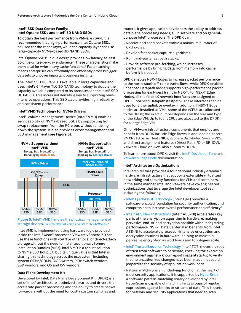
Intel® VMD Technology for NVMe DriversIntel® Volume Management Device (Intel® VMD) enables serviceability of NVMe-based SSDs by supporting hot swap replacement from the PCIe bus without shutting down the system. It also provides error management and LED management (see Figure 5).
NVMe Support withoutIntel® VMD
Storage Bus Events/Error Handling by BIOS or OS
NVMe Support withIntel® VMD
Storage Bus Events/Error Handling by Storage Driver
NVMe Driver Intel VMD-enabledNVMe Driver
Processor
Intel VMD
OS/PCI-busDriver
NVMeSSD
NVMeSSD
NVMeSSD
OS/PCI-busDriver
NVMeSSD
NVMeSSD
NVMeSSD
PCIe
Figure 5. Intel® VMD handles the physical management of storage devices. Source: colfax-intl.com/Servers/CX1265i-NVMe-XR7
Intel VMD is implemented using hardware logic provided inside the Intel® Xeon® processor. VMware vSphere 7.0 can use these functions with vSAN or other local or direct-attach storage without the need to install additional vSphere Installation Bundles (VIBs). Intel VMD is a robust solution to NVMe SSD hot plug, but its unique value is that Intel is sharing this technology across the ecosystem, including system OEMs/ODMs, BIOS writers, PCIe switch vendors, SSD vendors, and OS and ISV vendors.
Data Plane Development KitDeveloped by Intel, Data Plane Development Kit (DPDK) is a set of Intel® architecture-optimized libraries and drivers that accelerate packet processing and the ability to create packet forwarders without the need for costly custom switches and
routers. It gives application developers the ability to address data plane processing needs, all in software and on general-purpose Intel® processors. The DPDK can:
• Receive and send packets within a minimum number of CPU cycles.
• Develop fast packet capture algorithms.
• Run third-party fast path stacks.
• Provide software pre-fetching, which increases performance by bringing data from memory into cache before it is needed.
DPDK enables NSX-T Edges to increase packet performance to the north-south off-ramp traffic flows, while DPDK-enabled Enhanced Datapath mode supports high-performance packet processing for east-west traffic in NSX-T. For NSX-T Edge Nodes, all the fp-ethX network interfaces are assigned to DPDK Enhanced Datapath (fastpath). These interfaces can be used for either uplink or overlay. In addition, if NSX-T Edge nodes are installed as VMs, some of the vCPUs are allocated to the DPDK; the exact number depends on the size and type of the Edge VM. Up to four vCPUs are allocated to the DPDK for a large Edge VM.
Other VMware infrastructure components that employ and benefit from DPDK include Edge firewalls and load balancers, VMXNET3 paravirtual vNICs, vSphere Distributed Switch (VDS), and direct assignment features (Direct Path I/O or SR-IOV). VMware Cloud on AWS also supports DPDK.
To learn more about DPDK, visit the Intel® Developer Zone and VMware’s Edge Node documentation.
Intel® Architecture OptimizationsIntel architecture provides a foundational industry-standard hardware infrastructure that supports extensible virtualized networking and security functions for VMs and containers. In the same manner, Intel and VMware have co-engineered optimizations that leverage the Intel developer tool set, including the following:
• Intel® QuickAssist Technology (Intel® QAT) provides a software-enabled foundation for security, authentication, and compression to increase overall performance and efficiency.7
• Intel® AES New Instructions (Intel® AES-NI) accelerates key parts of the encryption algorithm in hardware, making pervasive, end-to-end encryption possible without degrading performance. NSX-T Data Center also benefits from Intel AES-NI to accelerate processor-intensive encryption and decryption routines in hardware, helping to maintain pervasive encryption as workloads and topologies scale.
• Intel® Trusted Execution Technology (Intel® TXT) moves the root of trust from software to hardware, checking the execution environment against a known-good image at startup to verify that no unauthorized changes have been made that could jeopardize the security of application workloads.
• Pattern matching is an underlying function at the heart of most security applications. It is supported by HyperScan, a software pattern-matching library developed by Intel. HyperScan is capable of matching large groups of regular expressions against blocks or streams of data. This is useful for network and security applications that need to scan
Reference Architecture | Modernize the Data Center for Hybrid Cloud 6
large amounts of data quickly. For example, NSX-T Data Center’s IDS and IPS use HyperScan.
• 2nd Gen Intel Xeon Scalable processors enhance NSX-T Data Center and help reduce overhead for near-native I/O performance with SR-IOV.
Cloud Infrastructure
VMware Cloud FoundationVMware Cloud Foundation provides a simplified path to hybrid/multicloud through an integrated software platform for both private and public cloud environments. It offers a complete set of software-defined services for compute, storage, network, and security, along with application-focused cloud management capabilities. The result is a simple, security-enabled, and agile cloud infrastructure on-premises and in as-a-service public cloud environments. The solution is built from a number of key components:
VMware SDDC ManagerSoftware-Defined Data Center (SDDC) Manager manages the bring-up of the VMware Cloud Foundation system, creates and manages Workload Domains, and performs lifecycle management to keep the software components up to date. SDDC Manager also monitors the logical and physical resources of VMware Cloud Foundation.
VMware vSphere with Tanzu Workload ManagementVMware vSphere extends virtualization to storage and network services and adds automated, policy-based provisioning and management. vSphere is the starting point for building an SDDC platform. VMware vSphere with Tanzu enables streamlined development, agile operations, and accelerated innovation for all enterprise applications. It consists of two core components: ESXi and vCenter Server. ESXi is the virtualization platform used to create and run VMs and appliances, while vCenter Server manages multiple ESXi hosts as clusters, using shared pool resources.
VMware vSphere with Tanzu workload management enables the deployment and operation of compute, networking, and storage infrastructure for vSphere with Tanzu. It makes it possible to use vSphere as a platform for running Kubernetes workloads natively on the hypervisor layer. Kubernetes workloads may be run directly on ESXi hosts and upstream Kubernetes clusters can be created within dedicated resource pools by using the TKG Service. See Running Tanzu Kubernetes Clusters in vSphere with Tanzu Documentation for details.
Cloud Builder VMThis is the VM appliance used for automated deployment of the entire stack.
VMware NSX-T Data CenterNSX-T Data Center (formerly NSX-T) is the network virtualization platform that enables a virtual cloud network with a software-defined approach. Working like a network hypervisor, it reproduces a complete set of Layer 2 through Layer 7 networking services: routing, switching, access control, firewalls, QoS, and DHCP in software. All these components can be used in any combination to create isolated virtual networks on demand. The services can then be extended to a variety
of endpoints within and across clouds. Starting with VMware Cloud Foundation 4.0, both management and VI Workload Domain types support the NSX-T Data Center platform.
VMware vRealize SuiteVMware vRealize Suite is a multicloud cloud management solution that provides IT organizations with a modern platform for infrastructure automation, consistent operations, and governance based on DevOps and machine-learning principles.
VMware Tanzu Kubernetes Grid (TKG) Service for vSphereTKG is available in several offerings and is used to provision and manage the lifecycle of Tanzu Kubernetes clusters, which are proprietary installations of Kubernetes open-source software, built and supported by VMware.
To learn more about TKG offerings, visit the VMware with Tanzu webpage.
This Reference Architecture uses the VMware TKG for vSphere offering, which is now integrated with vSphere 7.0 and is available starting from VMware Cloud Foundation 4.0. It runs on the Supervisor Clusters in vSphere with Tanzu and can be used to create conformant Kubernetes clusters that are optimized for vSphere. Check the Running Tanzu Kubernetes Clusters in vSphere with Tanzu Documentation for details.
VMware Cloud on AWSVMware Cloud on AWS is a hybrid cloud solution that allows easy extension, migration, and modernization of applications, and protection of applications in the public cloud. The VMware Cloud on AWS infrastructure is delivered by the same vSphere-based SDDC stack that is used on-premises. The solution takes advantage of existing tools, processes, and familiar VMware technologies, along with native integration with AWS. This makes it easy to adopt, greatly reduces service disruption associated with migrating critical services to the cloud, and eliminates the need for rearchitecting the environment to suit a public cloud infrastructure.
The enterprise-grade infrastructure is delivered as a service, with the SDDC provision time under two hours8 and has pre-configured vSAN storage, networking, compute, and security. VMware Cloud on AWS can also autoscale nodes as needed, depending on CPU, memory, and storage requirements. Typically, autoscaled nodes can be scaled up or down in just a few minutes.
VMware Cloud Bare-Metal TypesThe latest addition to VMware Cloud on AWS bare-metal infrastructure is a new node type named “i3en.metal.” i3en.metal bare-metal instances aim to address a variety of workloads, including data- or storage-intensive workloads requiring high random I/O access. Such workloads include relational databases and data warehousing. i3en.metal instances are also ideal for workloads that require end-to-end security.
Based on the 2nd Generation Intel Xeon Scalable processors, i3en.metal instances provide 96 logical cores with hyper-threading enabled, 768 GB of memory, and 46 TB raw storage capacity per host, with an additional 6.5 TB cache capacity, delivered with low-latency NVMe-based SSDs. i3en.metal instances extend the security capabilities of VMware Cloud on AWS by providing in-transit hardware-level

Reference Architecture | Modernize the Data Center for Hybrid Cloud 7
encryption between instances within the SDDC boundaries. This encryption seamlessly uses the AWS Key Management Service (KMS) to enable security for data both at rest and in-transit when using i3en.metal instances.
Check the announcement on the VMware Cloud Community blog for more details.
Tanzu Kubernetes Grid on VMware CloudOne of TKG offerings—TKG Plus—is fully supported by VMware when deployed to SDDC on VMware Cloud on AWS. TKG Plus includes the core binaries to install TKG clusters on VMware Cloud on AWS and also customer reliability engineering support and services to assist customers in successfully planning, deploying, and maintaining their Kubernetes environment. With TKG Plus running on VMware Cloud on AWS, customers can deploy a production-ready infrastructure that delivers single or multiple Kubernetes workload clusters. Refer to the TKG Plus on VMware Cloud on AWS solution brief for more information.
Edge Extensions – Optional Components
VMware NSX Advanced Load BalancerThe VMware NSX Advanced Load Balancer (Avi Networks) provides multicloud load balancing, web application firewall, and container ingress services across on-premises data centers and any cloud. Moving from appliance-based load balancers to the software-defined NSX Advanced Load Balancer can enable organizations to modernize load-balancing services with efficient use of standard computing infrastructure and reduce overprovisioning. Because the NSX Advanced Load Balancer can elastically scale load-balancing capacity up or down based on demand, applications can better utilize available compute power from Intel Xeon Scalable processors. For enterprises moving to software-defined data centers, the combination of the NSX Advanced Load Balancer deployed on servers with Intel Xeon Scalable processors represents a high-performance solution to load balance large volumes of encrypted traffic.
Principled Technologies tested a cluster of 16 Intel Xeon Scalable processor-powered servers with 64 virtual load balancers to explore how many SSL transactions per second the solution could handle. Processing and offloading encrypted transactions is a computationally intensive duty. However, the solution based on VMware and Intel® technologies was capable of handling an average of 1.085 million SSL transactions per second using 64 distributed load balancers to represent a single virtual service.9
These results indicate that even at times of heavy traffic, the elastically scalable NSX Advanced Load Balancer solution on Intel Xeon Scalable processor-powered servers can keep transactions moving and web traffic flowing smoothly.
According to Avi Networks, using Intel Xeon Scalable processors with Intel AES-NI to offload more cryptographic workloads into dedicated rather than general-purpose instructions enhanced the solution load-balancing performance. For maximum performance, Avi Networks recommends using the latest Intel® NICs that support DPDK for fabric elasticity without loss of capacity and linear scale from 2nd Generation Intel Xeon Scalable processors.
VMware SD-WAN by VeloCloudVeloCloud cloud-delivered software-defined WAN (SD-WAN) enables enterprises to more securely support application growth, network agility, and simplified branch and end-point implementations while delivering high-performance, reliable access to cloud services, private data centers and software-as-a-service (SaaS)-based enterprise applications. With VeloCloud cloud-delivered SD-WAN, service providers can increase service innovation by delivering elastic transport, performance for cloud applications, and a software-defined edge that can orchestrate multiple services to meet customer needs. The SD-WAN platform takes advantage of both Intel architecture and DPDK to deliver fast data-plane performance for virtualized SD-WAN, security, and other network functions. This helps enterprises reduce the costs associated with procuring and maintaining multiple hardware appliances, increase WAN operational efficiencies, and improve the security posture at the branch. The ability to innovate and add features through updates to the VeloCloud software running on Intel architecture-based hardware can continue to meet evolving branch needs for application performance and reliability.
VMware HCX VMware HCX is an application mobility platform that is designed for simplifying application migration, workload rebalancing, and business continuity across data centers and clouds. It enables customers to migrate workloads between public clouds and data centers without any modification to applications or VM configurations. It provides full compatibility with the VMware software stack and helps make the migration simple, highly secure, and scalable.
Source Data Center
VM VM VM
VMware NSX
VMware vSphere
VMware vSAN
VIRTUALDISTRIBUTED SWITCH
Remote Data Center
VM VM VM
VMware NSX
VMware vSphere
VMware HCX
VMware vSAN
VIRTUALDISTRIBUTED SWITCH
Figure 6. VMware HCX overview. Source: docs.vmware.com/en/VMware-HCX/services/install-checklist/GUID-DE0AD0AE-A6A6-4769-96ED-4D200F739A68.html
The HCX Multi-Site Service mesh provides a security-enabled pipeline for migration, extension, and VM protection between two connected VMware HCX sites (see Figure 6). It can be used to extend VLANs and retain IP and MAC addresses, as well as existing network policies, during migration between two sites. It also enables flexibility when planning complex, growing workloads across physical sites.
Note: When this reference architecture was written, VMware Cloud Foundation 4.0.1 did not support the HCX functionality. This is most likely a temporary issue, as the previous versions of VMware Cloud Foundation supported HCX. VMware states that it plans on adding HCX support to VMware Cloud Foundation 4.0 in the future releases.

Reference Architecture | Modernize the Data Center for Hybrid Cloud 8
Data Warehousing Building BlocksData warehouses are considered one of the core components of business intelligence. They are a central location to store data from one or more disparate sources as well as current and historical data. Numerous methods can be used to organize a data warehouse. Hardware, software, and data resources are the main components of this architecture, and VMware Cloud Foundation is an excellent platform on which to deploy data warehousing solutions (see Figure 7).
Data Warehousing (VMs)
Software-Defined data Center: VMware Cloud Foundation with Tanzu Kubernetes Grid Services
Software-Defined Networking: VMware NSX-T Data Center
Software-Defined Storage: VMware vSAN External Datastore
Management: VMware vCenter
HypervisorVMware ESXi
APPOS
APPOS
APPOS
APPOS
APPOS
…Machine-Learning Workloads
…
ESXi 1 ESXi 2 ESXi 3 ESXi n…
Software-Defined Automation: VMware vRealize Suite
CONTAINER CONTAINERCONTAINER CONTAINER
Figure 7. VMware Cloud Foundation can be used for all data analytics, AI, and machine-learning workloads.
The VMware hybrid/multicloud platform supports data warehousing, including industry-proven solutions based on Microsoft SQL Server 2019 or Oracle Database 19c.
The entire platform runs on vSAN, which provides additional storage policy configuration options in terms of data redundancy (multiple redundancy levels are available). vSAN can be used by both platform administrators and end users (such as when processing persistent volume claims on Kubernetes deployments) to obtain the maximum usage of the entire platform storage system.
Analytics and AI Building BlocksEnterprises need high-performance data analytics and AI to remain competitive. They require flexible solutions that can run traditional data analytics and AI applications. The VMware hybrid/multicloud platform includes components that take advantage of performance optimizations for Intel hardware. Intel supports developing machine-learning workloads at multiple layers in the solution stack. These building blocks enable enterprises to quickly operationalize analytics, AI, and machine-learning workloads because they are already optimized for Intel architecture and have been verified with multiple production deployments. Therefore, enterprises can immediately begin to use them.
This reference architecture demonstrates how to train a machine-learning model and then how it can be deployed on a hybrid/multicloud cluster. It also shows how Intel architecture-optimized deep learning libraries can be used to boost inference performance.
This section contains a short explanation of how Intel helps developers on multiple layers to build and optimize their analytics or AI solutions.
Intel® oneAPI InitiativeModern workload diversity necessitates the need for architectural diversity; no single architecture is best for every workload. XPUs, including CPUs, GPUs, FPGAs, and other accelerators, are required to extract high performance. Intel® oneAPI products will deliver the tools needed to deploy applications and solutions across these architectures. Its set of complementary toolkits—a base kit and specialty add-ons—simplify programming and help developers improve efficiency and innovation. The core Intel oneAPI DPC++ Compiler and libraries implement the oneAPI industry specifications available at oneapi.com.
Intel oneAPI Base Toolkit (Beta) is a foundational kit that enables developers of all types to build, test, and deploy performance-driven, data-centric applications across CPUs, GPUs, and FPGAs.
In addition, there are domain-specific toolkits that can be used for specialized workloads that are powered or based on the oneAPI Base Toolkit. Examples include the following:
• Intel® AI Analytics Toolkit (Beta) for accelerating end-to-end machine-learning and data science pipelines:
n Intel® Optimization for TensorFlow
n PyTorch Optimized for Intel® Technology
n Intel® Distribution for Python
n Intel® Optimization of Modin (available through Anaconda only)
n Model Zoo for Intel® architecture
n Intel® AI Quantization Tools for TensorFlow
• Intel® Distribution of OpenVINO™ Toolkit for deploying high-performance inference applications from device to cloud. This toolkit includes:
n OpenCV: Optimized Functions for Intel® Accelerators
n Intel® Deep Learning Deployment Toolkit
n Inference Support
n Deep Learning Workbench
• Intel oneAPI DL Framework Developer Toolkit (Beta) for building deep learning frameworks or customizing existing ones. This toolkit includes:
n Intel oneAPI Collective Communications Library
n Intel oneAPI Deep Neural Network Library
DataRobotThis solution demonstrates DataRobot, a popular automated machine-learning platform that takes advantage of optimizations for Intel architecture.10 Organizations worldwide use DataRobot to empower the teams they already have in place to rapidly build and deploy machine-learning models and create advanced AI applications. With a library of hundreds of powerful open-source machine-learning algorithms, the DataRobot platform encapsulates many best practices and helps to accelerate and scale data science capabilities while increasing transparency, accuracy, and collaboration.

Reference Architecture | Modernize the Data Center for Hybrid Cloud 9
Several DataRobot features make it a popular choice in the AI market:
• Selecting the proper model for a given problem is often tedious and difficult. Automated machine learning provided by DataRobot makes it possible to quickly and efficiently build and train tens or even hundreds of algorithms. After the training is completed, DataRobot presents the models in a list, ranked in order of the selected performance metric. To make it even easier to choose a model, DataRobot automatically flags which model is most accurate and which model is best suited for deployment.
• Model tuning is easy with DataRobot. The tool automatically runs dozens of models with preset settings that have been thoroughly tested to verify that they result in highly accurate models. Enterprises can take advantage of this pre-work so they can focus on choosing the one that is most accurate for their data. DataRobot also makes it easy to manually tune models.
• DataRobot makes it easy to explain AI through human-friendly visual insights and automated model documentation with blueprints that describe each step in the modeling process and the algorithms used. Enterprises can evaluate any model using several tools.
• All DataRobot models are ready for production and can be deployed with a single click to make AI fully operational. Enterprises can monitor models using a centralized dashboard to view service health and usage in real time. They can also manage model accuracy to easily understand which features have drifted and deploy updates with no service interruption.
Self-Service Application CatalogsTanzu Application Catalog (TAC) is a customizable selection of open-source software from the Bitnami collection that is continuously maintained and verifiably tested for use in production environments. Bitnami, acquired by VMware in 2019, is a leading publisher of prepackaged open source software. TAC is available as a service on the VMware Cloud Services Portal and can be consumed by each edition of TKG and third-party applications like Kubeapps.
TAC gives developers the productivity and agility of prepackaged apps and components, while enabling operators to meet the stringent security and transparency requirements of enterprise IT. It delivers a set of prepackaged container images and Helm charts, chosen and curated by the customer IT operators, to create an IT-approved “private” catalog of the applications available to enterprise end users and developers.
Containers can be built on the customer “golden” OS image, or the customer can select one maintained with best practices by VMware. Each container is continuously updated and comes with metadata proving the reliability of the software within. IT Information Security teams and platform operators can access container metadata through the graphical user interface (GUI) or by using APIs.
Vital compliance and audit details are available, including:
• A history of updates to each container and Helm chart
• A manifest of libraries, binaries, and software license terms in every container
• Results of tests run in every environment (Linux distribution) relevant to the customer for every update
• Proof of open-source security (known CVE) and virus (ClamAV) scans
• Links to the upstream source of libraries and binaries included in every container
Developers who use TAC can simply replace the containers and Helm charts they were maintaining manually for production workloads with IT-approved containers and charts built and maintained by VMware. These can be downloaded for local development, or they can be used in production. For development teams that rely on hand-built containers, TAC can be a leap forward in efficiency, compliance, and better security. For more information, visit the TAC web page.
In addition, this reference architecture demonstrates fast and easy deployment of applications using Kubeapps.
Kubeapps is a web application designed for deploying and managing applications in Kubernetes clusters (see Figure 8) that allows the user to accomplish the following tasks:• Browse and deploy Helm charts from chart repositories• Inspect, upgrade, and delete Helm-based applications
installed in the cluster• Add custom and private chart repositories (including TAC)• Browse and provision external services from the Service
Catalog and available Service Brokers• Connect Helm-based applications to external services with
Service Catalog Bindings• Secure authentication and authorization based on
Kubernetes Role-Based Access Control
< >< >
Figure 8. Bitnami Kubeapps user interface.
Using Kubeapps, users can choose from applications that their IT department has selected and packaged, or use any freely available repositories. For more information on how to use Kubeapps, refer to the “Kubeapps Usage” section in Appendix A.

Reference Architecture | Modernize the Data Center for Hybrid Cloud 10
Platform-Verified Analytics/AI Workload PerformanceThe following sections discuss deep learning inference and machine-learning model training workloads.
Deep-Learning InferenceVMware Cloud Foundation 4.0.1 introduced Intel DL Boost with VNNI to VMs. We ran experiments to show the improvement of inference performance with an Intel architecture-optimized container stack that uses the new VNNI instruction set.
Image classification is one of the most popular use cases for deep learning. Our tests benchmarked the ResNet50 v1.5 topology with int8 and fp32 precision, using the TensorFlow distribution from the Intel architecture-optimized container stack with Intel’s Model Zoo pretrained models. The VMs on which the benchmark ran used the entire physical node available through VMware software. The VMs used 80 vCPUs for the Base configuration and 96 vCPUs for the Plus configuration.
We ran three tests:11
• Compare throughput from the default TensorFlow container against a container using the Intel Optimization for TensorFlow. As Figure 9 shows, framework optimizations from Intel Optimization for TensorFlow can provide 2.33X improvement for the Base configuration and 2.61X performance improvement for the Plus configuration.
• Compare the results of running VMware Cloud Foundation 4.0.1 (which takes advantage of Intel DL Boost and VNNI) against the reference architecture for VMware Cloud Foundation 3.9 (which does not use Intel DL Boost or VNNI). As shown in Figure 10, the newer system provided a 1.53X improvement over the older system for the Base configuration and a 1.64X improvement for the Plus configuration.
• Compare the performance improvement of Intel DL Boost with VNNI using int8 precision against fp32 precision. As shown in Figure 11, int8 precision enabled a 4.1X improvement for the Base configuration and a 4.38X improvement for the Plus configuration. For a small decrease in precision, performance quadrupled.
As the above results show, the hardware and software optimizations for inference have a huge impact on improving the performance of inference. VMware Cloud Foundation 4.0.1 is an excellent example of how software can take advantage of hardware innovations like Intel DL Boost and VNNI to deliver significantly better performance results.
For detailed instructions regarding the benchmark, refer to the “Running the TensorFlow Benchmark with an Intel® architecture-optimized container stack (Inference Benchmarks Reproduction)” section in Appendix A.
ResNet50 Performance ComparisonDefault vs. Intel® Optimized for TensorFlow
256 BATCH SIZE | HIGHER IS BETTER
Base Configuration Plus Configuration0.0
0.5
1.0
1.5
2.0
2.5
2.33x IMPROVEMENTIntel® Optimized for TensorFlow
2.61x IMPROVEMENTIntel® Optimized for TensorFlow
Nor
mal
ized
Per
form
ance
(fra
mes
per
sec
ond)
Baselinefor Default TensorFlow
Baselinefor Default TensorFlow
Figure 9. Using the Intel® architecture-optimized version of TensorFlow more than doubled the performance of the ResNet 50 v1.5 topology for the Base configuration, and almost tripled the throughput of the Plus configuration.
ResNet50 v1.5 Performance Comparison for VMware Cloud Foundation
v3.9 vs. v4.0.1 with Intel® DL Boost and VNNI 128 BATCH SIZE | HIGHER IS BETTER
Base Configuration Plus Configuration0.0
0.5
1.0
1.5
1.53x IMPROVEMENTwith v4.0.1 with
Intel® DL Boost and VNNI
1.64x IMPROVEMENTwith v4.0.1 with
Intel® DL Boost and VNNI
Nor
mal
ized
Per
form
ance
(fra
mes
per
sec
ond)
Baseline for v3.9Base Configuration
Baseline for v3.9Plus Configuration
Figure 10. Using VMware Cloud Foundation 4.0.1 with Intel® DL Boost and VNNI significantly improves the performance of the ResNet50 v1.5 topology for both the Base configuration and the Plus configuration.
ResNet50 v1.5 Performance Comparison for VMware Cloud Foundation 4.0.1 FP32 vs. INT8 with Intel® DL Boost and VNNI
256 BATCH SIZE | HIGHER IS BETTER
Base Configuration Plus Configuration0
1
2
3
4
4.1x IMPROVEMENTusing INT8 with Intel® DL Boost
and VNNI
4.38x IMPROVEMENTusing INT8 with Intel® DL Boost
and VNNI
Nor
mal
ized
Per
form
ance
(fra
mes
per
sec
ond)
Baseline for FP32Base Configuration
Baseline for FP32Plus Configuration
Figure 11. Using int8 precision instead of fp32 precision more than quadrupled the performance of the ResNet 50 v1.5 topology for the Base configuration and the Plus configuration.

Reference Architecture | Modernize the Data Center for Hybrid Cloud 11
Machine-Learning Model TrainingThe high-level goal of the workload example described here is to show how quick and easy it is to train a variety of simple models that allow prediction of important results. Advanced tools like DataRobot make the process more convenient than ever before.
1. Data upload. DataRobot allows choosing the JDBC source or uploading data from a URL, Apache Hadoop’s Highly Distributed File System (HDFS), or locally stored files. The tool can handle .csv, .tsv, .dsv, .xls, .xlsx, .sas7bdat, .parquet, .avro, .bz2, .gz, .zip, .tar, and .tgz file formats. The choice is wide for a better user experience. The dataset chosen for demo purposes consists of COVID-19 data at the County Level and is available here.
2. Explore the AI catalog. Uploaded datasets are available in the “AI catalog.” Basic data analysis and dataset summaries can be found there, as well as basic information and a features list.
3. Explore and visualize the data. Convenient visualization is provided to better understand the data. This can help users choose important features for training. DataRobot automatically explores the dataset and identifies variable types and numerical statistics such as mean, median, and standard deviation. To see the details, click on the feature’s name.
4. Create a new project. A new project can be created to start work on the data. DataRobot will automatically analyze the data and add suggestions. For example, DataRobot can create new fields based on existing features.
5. Start the training process. Choose the target feature by entering its name. The problem will be automatically identified based on the field type (for example, classification or regression). Click the Start button; the Autopilot lets DataRobot choose which training algorithms (blueprints) to check.
6. Refine the model. DataRobot’s algorithms can again analyze data and check for redundancies or exclude one or more features that are at risk of causing target leakage and any features providing little or no information that is useful for modeling.
The platform also decides which features are the most important for the result. The progress of these processes appears in the right column.
7. Compare algorithms. DataRobot trains models using different algorithms and compares them for the best result. However, the platform does not train all models using the whole dataset. Based on results and performance for a part of the dataset, it can decide which algorithms are the most promising and proceed only with them. This approach saves time and resources. Users can compare algorithms on the leaderboard. Data is updated live during the training. When the process is completed, DataRobot shows its recommendations by labeling the best models, such as “Recommended for development,” “Most accurate,” and “Fast & Accurate” to help with algorithm choice.
8. Deploy the model. All models are available for download and manual deployment. The user can also deploy them automatically, which can quickly start the prediction process. All data necessary to use the model after deployment can be found in the user interface.
9. Start the prediction process. DataRobot provides the REST API that can be used to make an inference. This allows users to use the model with a variety of programming languages. Also, instead of calling the API directly, users can take advantage of an auto-generated Python script. This code can be found in the user interface and can be adjusted as needed. It can be copied and become a part of a bigger system or simply remain as-is.
10. Monitor the model’s health. Users can observe the model behavior in the user interface. The users can track the number of predictions made, requests, data error rate, and mode. Data drift tracking is also available.

Reference Architecture | Modernize the Data Center for Hybrid Cloud 12
Build Once, Run Anywhere The machine-learning use case described in this document consists of the following elements:
• Model training using DataRobot
• Publication of the model (inference engine and the scorer) in an internal application catalog
• Deployment of the scorer
The model-training process is described in the previous section, “Machine-Learning Model Training.” After finishing this step, the model binaries (scorer) either for Python or Java runtimes can be obtained.
There are three ways to deploy the model:
• Use the Prediction Server that is a part of a main DataRobot installation. It gives you more features—such as data drift tracking—but is the least flexible solution when considering portability.
• Use the Standalone Prediction Server (SPS). An instance of SPS can be set up anywhere and is independent of the main DataRobot instance. Users can upload models downloaded from the main DataRobot instance to the SPS instance. SPS provides a REST API for requesting predictions.
• Use the Portable Prediction Server (PPS). This is the deployment method illustrated in this reference architecture. The PPS allows creation of images that include both the server and the model. It is very convenient, and the container can be set up in any place where Docker is available. It is the easiest way to serve a model since it does not require additional SPS installation and maintenance, but the whole solution is delivered as one container.
A Docker image with model binaries and PPS (scorer) is automatically built and published to a container registry—this example uses Harbor. As an incubating Cloud Native Computing Foundation (CNCF) project, Harbor delivers compliance, performance, and interoperability to help enterprises consistently and securely manage images across cloud-native compute platforms like Kubernetes and Docker. With the scorer (or with any other app) accessible in the registry, it can be deployed on the environment of choice, whether it’s an on-premises cluster, private cloud, or public cloud.
User experience (both for business users and the operators of the platform) can be improved by publishing the scorer to an application catalog such as Kubeapps, so it can be deployed easily and quickly from a web user interface using just a few mouse clicks. Furthermore, there are solutions such as Keel available, that integrate with the container registry and use its webhooks to automatically detect if a new version of the application appears. In that case, Keel can seamlessly redeploy the application, replacing the current version with the new one.
The last step is model utilization. Many applications, deployed on many different environments and clusters, can call the Prediction Server and demand predictions. This can be done using DataRobot’s Python library or directly with a
REST API. In the provided example, the application deployed in the cloud (with the usage of Kubeapps) calls the scorer (container of PPS with the model) directly to visualize data.
Bill of MaterialsHardwareThe reference architecture described here can scale from a single rack with just eight servers up to 15 domains (one Management Domain and 14 Workload Domains) with up to 400 ESXi servers total. This reference architecture uses 12 Intel® servers, two top-of-rack Arista switches, and a single Quanta Cloud Technology management switch in a single rack. Additional racks can be added when needed.
The initial software imaging requires an additional server or laptop running virtualization software and a privately managed switch. These components are not part of the reference architecture and are not needed after completing the VMware Cloud Foundation imaging and bring-up process.
To demonstrate support for heterogeneous hardware configurations, this reference architecture uses two types of servers differing in the CPU model, memory size, and number of drives. Enterprises can modify the base vSAN ReadyNode configuration to some extent, adding more memory or drives, or replacing the CPU with a higher core-count or better clock-speed model. The general rules are described here.
In this reference architecture, each rack consists of a set of two top-of-rack switches and a single out-of-band management switch. In multirack deployments, an additional set of spine switches is recommended (usually installed in the second rack). Starting from VMware Cloud Foundation 3.0, VMware no longer certifies switch compatibility with VMware Cloud Foundation. For the networking components in this reference architecture, two models of network switches were used: two Arista DCS-7060CX2-32S-R for the data plane, and one Arista DCS-7010T-48-R for the management plane. Any network hardware with similar performance may be used instead. Table 1, on the next page, lists the hardware components of this reference architecture.
SoftwareThis reference architecture consists of two main software component suites: VMware Cloud Foundation and TKG Service. The latter requires multiple components and supporting infrastructure. In addition, several networking services like an enterprise NTP server and a DNS server are needed for seamless integration with the external networks and global time synchronization. Tables 2 and 3 provide software component information. For a complete list of requirements and prerequisites, refer to the official VMware documentation.
BIOS and Firmware ComponentsFrom the hardware perspective, Table 4 lists the firmware and driver versions that were used in this solution.

Reference Architecture | Modernize the Data Center for Hybrid Cloud 13
Table 1. Reference Architecture Hardware ComponentsManagement Cluster 4 Nodes
Base Workload Domain 4 Nodes
Plus Workload Domain 4 Nodes
Part DescriptionQty
(per Node) Part DescriptionQty
(per Node) Part DescriptionQty
(per Node)
Base SKU Intel® Server System VRN2208WFAF82R 1 Intel Server System
VRN2208WFAF82R 1 Intel Server System VRN2208WFAF83R 1
Mainboard Intel® Server Board S2600WF0R 1 Intel Server Board S2600WF0R 1 Intel Server Board S2600WF0R 1
CPU Intel® Xeon® Gold 6230 processor (20 cores, 2.1 GHz) 2 Intel® Xeon® Gold 6248
processor (20 cores, 2.5 GHz) 2 Intel® Xeon® Platinum 8268 processor (24 cores, 2.9 GHz) 2
Memory 32 GB RDIMM DDR4-2933 12 32 GB RDIMM DDR4-2933 1232 GB RDIMM DDR4-2666 12128 GB Intel® Optane™ PMem 12
Caching Tier
375 GB Intel® Optane™ SSD DC P4800X Series (PCIe x4 U.2) 2 375 GB Intel Optane SSD DC
P4800X Series (PCIe x4 U.2) 2 375 GB Intel Optane SSD DC P4800X Series (PCIe x4 U.2) 2
Capacity Tier
2 TB Intel® SSD DC P4510 Series (2.5” NVMe U.2) 4 2 TB Intel SSD DC P4510 Series
(2.5” NVMe U.2) 4 2 TB Intel SSD DC P4510 Series (2.5” NVMe U.2) 6
Boot Device
480 GB Intel SSD DC S4510 Series (M.2, 80 mm) 1 480 GB Intel SSD DC S4510
Series (M.2, 80 mm) 1 480 GB Intel SSD DC S4510 Series (M.2, 80 mm) 1
NIC Intel® Ethernet Converged Network Adapter X710-DA2 1 Intel Ethernet Converged
Network Adapter X710-DA2 1 Intel Ethernet Converged Network Adapter X710-DA2 1
Table 2. VMware Cloud Foundation Products and ServicesComponent Version BuildVMware Cloud Foundation bundle 4.0.1 16428904Cloud Builder VM 4.0.1 16428904VMware ESXi hypervisor 7.0b 16324942VMware vSAN 7.0 16324942VMware NSX-T Data Center 3.0.1 16404613VMware vCenter Server Appliance 7.0.0b 16386292VMware SDDC Manager 4.0.1 16428904VMware vRealize Suite Lifecycle Manager 8.1 Patch 1 16256499VMware Tanzu Kubernetes Grid Service for vSphere - June 23, 2020
Note: Only the main components are listed in Table 2. For information on other components, see the VMware Cloud Foundation release notes.
Table 3. Other Software ComponentsComponent VersionKubeapps 1.11.1TensorFlow image tensorflow/tensorflow:1.15.0-py3Intel® architecture-optimized distribution of TensorFlow image clearlinux/stacks-dlrs-mkl:v0.5.0DataRobot 6.0.0
Table 4. BIOS and Firmware ComponentsFirmware/Driver Name VersionBIOS 02.01.0011BMC 2.42ME 04.01.04.339SDR 1.99NIC firmware 7.30 0x80008387 1.2684.0NIC driver version 1.10.9.0Intel® Optane™ SSD DC P4800X E2010435Intel® SSD DC P4510 VDV10170Intel® Optane™ persistent memory firmware 01.02.00.5417
CPU microcodeBase: 0x05002f00 Plus: 0x05002f00 Management: 0x04002f00
Reference Architecture | Modernize the Data Center for Hybrid Cloud 14
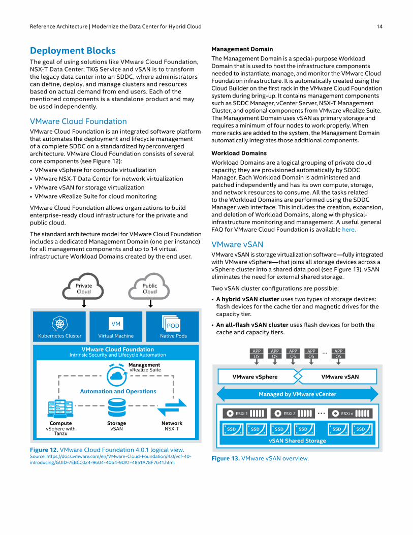
Deployment BlocksThe goal of using solutions like VMware Cloud Foundation, NSX-T Data Center, TKG Service and vSAN is to transform the legacy data center into an SDDC, where administrators can define, deploy, and manage clusters and resources based on actual demand from end users. Each of the mentioned components is a standalone product and may be used independently.
VMware Cloud FoundationVMware Cloud Foundation is an integrated software platform that automates the deployment and lifecycle management of a complete SDDC on a standardized hyperconverged architecture. VMware Cloud Foundation consists of several core components (see Figure 12): • VMware vSphere for compute virtualization • VMware NSX-T Data Center for network virtualization• VMware vSAN for storage virtualization • VMware vRealize Suite for cloud monitoring
VMware Cloud Foundation allows organizations to build enterprise-ready cloud infrastructure for the private and public cloud.
The standard architecture model for VMware Cloud Foundation includes a dedicated Management Domain (one per instance) for all management components and up to 14 virtual infrastructure Workload Domains created by the end user.
Kubernetes Cluster
Management
Automation and Operations
ComputevSphere with
Tanzu
StoragevSAN
NetworkNSX-T
Virtual Machine Native Pods
PrivateCloud
PublicCloud
VMware Cloud FoundationIntrinsic Security and Lifecycle Automation
VM PODPODPOD
vRealize Suite
Figure 12. VMware Cloud Foundation 4.0.1 logical view. Source: https://docs.vmware.com/en/VMware-Cloud-Foundation/4.0/vcf-40-introducing/GUID-7EBCC024-9604-4064-90A1-4851A78F7641.html
Management DomainThe Management Domain is a special-purpose Workload Domain that is used to host the infrastructure components needed to instantiate, manage, and monitor the VMware Cloud Foundation infrastructure. It is automatically created using the Cloud Builder on the first rack in the VMware Cloud Foundation system during bring-up. It contains management components such as SDDC Manager, vCenter Server, NSX-T Management Cluster, and optional components from VMware vRealize Suite. The Management Domain uses vSAN as primary storage and requires a minimum of four nodes to work properly. When more racks are added to the system, the Management Domain automatically integrates those additional components.
Workload DomainsWorkload Domains are a logical grouping of private cloud capacity; they are provisioned automatically by SDDC Manager. Each Workload Domain is administered and patched independently and has its own compute, storage, and network resources to consume. All the tasks related to the Workload Domains are performed using the SDDC Manager web interface. This includes the creation, expansion, and deletion of Workload Domains, along with physical-infrastructure monitoring and management. A useful general FAQ for VMware Cloud Foundation is available here.
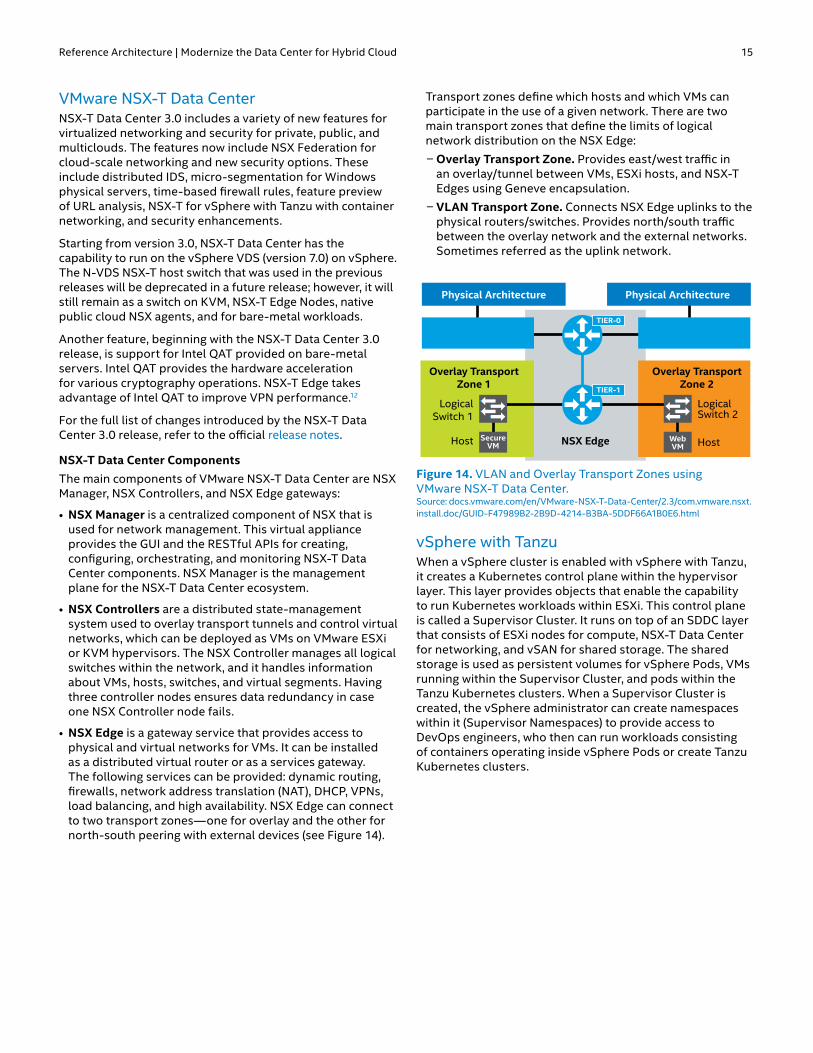
VMware vSANVMware vSAN is storage virtualization software—fully integrated with VMware vSphere—that joins all storage devices across a vSphere cluster into a shared data pool (see Figure 13). vSAN eliminates the need for external shared storage.
Two vSAN cluster configurations are possible:
• A hybrid vSAN cluster uses two types of storage devices: flash devices for the cache tier and magnetic drives for the capacity tier.
• An all-flash vSAN cluster uses flash devices for both the cache and capacity tiers.
VMware vSphere VMware vSANVMware vSphere VMware vSAN
APPOS
APPOS
APPOS
APPOS
APPOS
Managed by VMware vCenter
ESXi 1
SSD SSD
ESXi 2
SSD SSD
ESXi n
SSD SSD
vSAN Shared Storage
Figure 13. VMware vSAN overview.
Reference Architecture | Modernize the Data Center for Hybrid Cloud 15
VMware NSX-T Data CenterNSX-T Data Center 3.0 includes a variety of new features for virtualized networking and security for private, public, and multiclouds. The features now include NSX Federation for cloud-scale networking and new security options. These include distributed IDS, micro-segmentation for Windows physical servers, time-based firewall rules, feature preview of URL analysis, NSX-T for vSphere with Tanzu with container networking, and security enhancements.
Starting from version 3.0, NSX-T Data Center has the capability to run on the vSphere VDS (version 7.0) on vSphere. The N-VDS NSX-T host switch that was used in the previous releases will be deprecated in a future release; however, it will still remain as a switch on KVM, NSX-T Edge Nodes, native public cloud NSX agents, and for bare-metal workloads.
Another feature, beginning with the NSX-T Data Center 3.0 release, is support for Intel QAT provided on bare-metal servers. Intel QAT provides the hardware acceleration for various cryptography operations. NSX-T Edge takes advantage of Intel QAT to improve VPN performance.12
For the full list of changes introduced by the NSX-T Data Center 3.0 release, refer to the official release notes.
NSX-T Data Center ComponentsThe main components of VMware NSX-T Data Center are NSX Manager, NSX Controllers, and NSX Edge gateways:
• NSX Manager is a centralized component of NSX that is used for network management. This virtual appliance provides the GUI and the RESTful APIs for creating, configuring, orchestrating, and monitoring NSX-T Data Center components. NSX Manager is the management plane for the NSX-T Data Center ecosystem.
• NSX Controllers are a distributed state-management system used to overlay transport tunnels and control virtual networks, which can be deployed as VMs on VMware ESXi or KVM hypervisors. The NSX Controller manages all logical switches within the network, and it handles information about VMs, hosts, switches, and virtual segments. Having three controller nodes ensures data redundancy in case one NSX Controller node fails.
• NSX Edge is a gateway service that provides access to physical and virtual networks for VMs. It can be installed as a distributed virtual router or as a services gateway. The following services can be provided: dynamic routing, firewalls, network address translation (NAT), DHCP, VPNs, load balancing, and high availability. NSX Edge can connect to two transport zones—one for overlay and the other for north-south peering with external devices (see Figure 14).
Transport zones define which hosts and which VMs can participate in the use of a given network. There are two main transport zones that define the limits of logical network distribution on the NSX Edge:
n Overlay Transport Zone. Provides east/west traffic in an overlay/tunnel between VMs, ESXi hosts, and NSX-T Edges using Geneve encapsulation.
n VLAN Transport Zone. Connects NSX Edge uplinks to the physical routers/switches. Provides north/south traffic between the overlay network and the external networks. Sometimes referred as the uplink network.
NSX Edge WebVM Host
LogicalSwitch 2
Overlay TransportZone 2
TIER-0VLAN Transport
ZoneVLAN Transport
Zone
SecureVMHost
LogicalSwitch 1
Overlay TransportZone 1
TIER-1
Physical Architecture Physical Architecture
Figure 14. VLAN and Overlay Transport Zones using VMware NSX-T Data Center. Source: docs.vmware.com/en/VMware-NSX-T-Data-Center/2.3/com.vmware.nsxt.install.doc/GUID-F47989B2-2B9D-4214-B3BA-5DDF66A1B0E6.html
vSphere with TanzuWhen a vSphere cluster is enabled with vSphere with Tanzu, it creates a Kubernetes control plane within the hypervisor layer. This layer provides objects that enable the capability to run Kubernetes workloads within ESXi. This control plane is called a Supervisor Cluster. It runs on top of an SDDC layer that consists of ESXi nodes for compute, NSX-T Data Center for networking, and vSAN for shared storage. The shared storage is used as persistent volumes for vSphere Pods, VMs running within the Supervisor Cluster, and pods within the Tanzu Kubernetes clusters. When a Supervisor Cluster is created, the vSphere administrator can create namespaces within it (Supervisor Namespaces) to provide access to DevOps engineers, who then can run workloads consisting of containers operating inside vSphere Pods or create Tanzu Kubernetes clusters.

Reference Architecture | Modernize the Data Center for Hybrid Cloud 16
What Is a vSphere Pod?A vSphere Pod is a new construct introduced by vSphere with Tanzu. It is an equivalent of a Kubernetes Pod. A vSphere Pod is a VM running one or more containers, with a small footprint. Each vSphere Pod is an object in vCenter Server, and for networking needs, vSphere Pods use the topology provided by NSX-T Data Center. In this Reference Architecture we concentrate on using TKG clusters instead of vSphere Pods. You can read more about vSphere Pods versus Tanzu Kubernetes clusters here.
A Supervisor Cluster Architecture An overview of the Supervisor Cluster architecture is shown in Figure 15.
Aside from the regular ESXi components, there are some new elements:
• Spherelet process is a kubelet that is ported natively to ESXi and allows the ESXi host to become part of the Kubernetes cluster.
• Kubernetes control plane VMs are a total of three load-balanced machines for the Kubernetes control plane.
• Container Runtime Executive (CRX) includes a paravirtualized Linux kernel that works together with the hypervisor. CRX uses the same hardware virtualization techniques as VMs and has a VM boundary around it.
• Virtual Machine Service, Cluster API, and TKG Service are modules that run on the Supervisor Cluster and enable provisioning and management of Tanzu Kubernetes clusters.
Supervisor NamespaceThis namespace allows the vSphere administrator to define the resource boundaries where vSphere Pods and Tanzu Kubernetes clusters are created when using the TKG Service. The administrator can set limits for CPU, memory, and storage as well as the number of Kubernetes objects that can run within the namespace. A resource pool is created per each namespace in vSphere. User permissions can be set to users and groups to allow access to namespaces using an identity source that is associated with vCenter Single Sign-on. After the namespace is created, configured with resources, and set with access for users, the namespace can be accessed to run Kubernetes workloads and create Tanzu Kubernetes clusters by using the TKG Service.
Tanzu Kubernetes ClustersA Tanzu Kubernetes cluster (see Figure 16 on the next page) is a full distribution of the open-source Kubernetes software, signed and supported by VMware. You can use the TKG Service to provision Tanzu Kubernetes clusters on the Supervisor Cluster. The TKG Service API can be invoked by using kubectl and a YAML definition. Once deployed, Tanzu Kubernetes clusters can be accessed and used in the same way—and use the same tools—as a standard Kubernetes cluster. The entire k8s environment may exist in parallel to any regular VMs in the cluster, as seen in Figure 16. Each Namespace can be seen in the vSphere GUI as a Resource Pool.
From the logical overview the Tanzu Kubernetes Cluster exists within a Supervisor cluster. vSphere with Tanzu consists of a single availability zone within a single geographic region. See Figure 17 on the next page for a general overview.
vCenter ServervSphereAdmin
Supervisor Cluster
DevOps
ESXi Host ESXi Host ESXi Host
Spherelet
K8S Control Plane VM
vSphere Pod
hostd Spherelet
K8S Control Plane VM
hostd Spherelet
K8S Control Plane VM
hostd
CRX
vSphere Pod
CRX
vSphere Pod
CRX
vSphere Pod
CRX
VM VM
Figure 15. Supervisor Cluster architecture. Source: https://docs.vmware.com/en/VMware-vSphere/7.0/vmware-vsphere-with-kubernetes/GUID-3E4E6039-BD24-4C40-8575-5AA0EECBBBEC.html

Reference Architecture | Modernize the Data Center for Hybrid Cloud 17
Figure 16. An example of vSphere with Tanzu with Tanzu Kubernetes Clusters. Source: https://docs.vmware.com/en/VMware-vSphere/7.0/vmware-vsphere-with-kubernetes/GUID-3E4E6039-BD24-4C40-8575-5AA0EECBBBEC.html
Figure 17. Tanzu Kubernetes and VMware Cloud Foundation 4.0 overview. Source: https://docs.vmware.com/en/VMware-Validated-Design/6.0/sddc-architecture-and-design-for-a-vsphere-with-kubernetes-workload-domain/GUID-D72DB286-1907-4AF6-A644-42FBAB2BB7C7.html
vSphere Pod
Linux Container
Linux Container
vSphere Pod
Linux Container
Linux Container
vSphere Pod
Linux Container
Linux ContainervSphere
Pod VM VM VM VMvSpherePod
SupervisorNamespace
SupervisorNamespace
SupervisorNamespace
SupervisorNamespace
vSphere ClustervSphere Cluster
vSphere with NSX-T Data Center
SupervisorNamespace
VM vSpherePod
Tanzu Kubernetes Cluster
Tanzu Kubernetes Cluster
Tanzu Kubernetes Cluster
Supervisor Cluster
VMOperator
ClusterAPI
VMware Tanzu™DubernetesGrid™
Service VM
SC ControlPlane Node
VM
SC ControlPlane Node
VM
SC ControlPlane Node
Supervisor Cluster
VMOperator
ClusterAPI
VMware Tanzu DubernetesGrid
Service VM
SC ControlPlane Node
VM
SC ControlPlane Node
VM
SC ControlPlane Node
PodRUNC
Containers
PodRUNC
Containers
Tanzu Kubernetes
Cluster Worker Node
VM
Tanzu Kubernetes
Cluster Worker Node
VM
Tanzu Kubernetes
Cluster Worker Node
VM
Tanzu Kubernetes
Cluster Worker Node
VM
Tanzu Kubernetes
Cluster Worker Node
VM
Tanzu Kubernetes
Cluster Worker Node
VM
Tanzu Kubernetes
Cluster Worker Node
VM
Tanzu Kubernetes
Cluster Worker Node
VM
Tanzu Kubernetes
Cluster Worker Node
VM
Tanzu Kubernetes
Cluster Worker Node
VM
Tanzu Kubernetes
Cluster Worker Node
VM
Tanzu Kubernetes
Cluster Worker Node
VM
vSphere with Tanzu Logical Overview
Virtual Infrastructure Shared Edge and Workload
vSphere Distributed Switch with NSX-T vSphere Distributed Switch with NSX-T
WorkerNode
WorkerNode
WorkerNode
ControlPlaneNode
WorkerNode
WorkerNode
WorkerNode
Cluster 1Tanzu Kubernetes
Supervisor Cluster
vSpherePod
vSpherePod
vSpherePod
Namespace 1
vSpherePod
vSpherePod
vSpherePod
ControlPlaneNode
ControlPlaneNode
ControlPlaneNode
Namespace n Control Plane
Cluster nTanzu Kubernetes
NSX-TEdges
Virtual Infrastructure Management
Other Management Applications
NSX-TManagers
(Mgmt)
vCenterServer(Mgmt)
vCenterServer
(Workload)
SDDCManager
NSX-TManagers
(Mgmt)
NSX-TManagers
(Workload)
Managed by:Workload Domain vCenter Workload Cluster
Managed by:Workload Domain vCenter Workload Cluster
ESXiTransport
Node
ESXiTransport
Node
ESXiTransport
Node
ESXiTransport
Node
ESXiTransport
Node
ESXiTransport
Node
ESXiTransport
Node
ESXiTransport
Node
Network: Internal SDDC
Network: External(Internet/Corporate)
Shared Edge and Workload Cluster Management Cluster
APPOSAPPOSAPPOS
APPOS
APPOSAPPOSAPPOS
APPOSAPPOSAPPOS
APPOSAPPOSAPPOS
APPOSAPPOSAPPOS
APPOSAPPOSAPPOS
APPOS
APPOS
APPOS
APPOSControl
PlaneNode
ControlPlaneNode
ControlPlaneNode
ControlPlaneNode
ControlPlaneNode
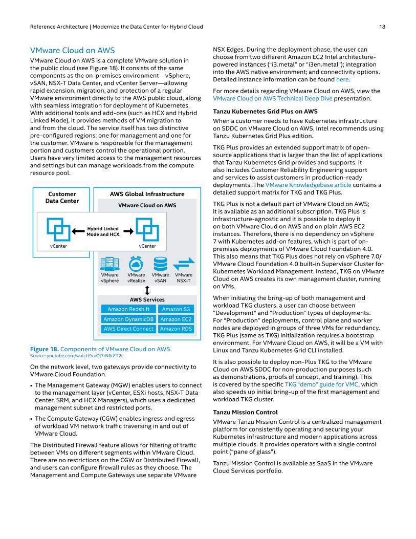
Reference Architecture | Modernize the Data Center for Hybrid Cloud 18
VMware Cloud on AWSVMware Cloud on AWS is a complete VMware solution in the public cloud (see Figure 18). It consists of the same components as the on-premises environment—vSphere, vSAN, NSX-T Data Center, and vCenter Server—allowing rapid extension, migration, and protection of a regular VMware environment directly to the AWS public cloud, along with seamless integration for deployment of Kubernetes. With additional tools and add-ons (such as HCX and Hybrid Linked Mode), it provides methods of VM migration to and from the cloud. The service itself has two distinctive pre-configured regions: one for management and one for the customer. VMware is responsible for the management portion and customers control the operational portion. Users have very limited access to the management resources and settings but can manage workloads from the compute resource pool.
VMware Cloud on AWS
CustomerData Center
AWS Services
Amazon Redshift Amazon S3
Amazon DynamicDB Amazon EC2
AWS Direct Connect Amazon RDS
VMwareNSX-T
VMwarevSAN
VMwarevRealize
VMwarevSphere
vCenter vCenter
Hybrid LinkedMode and HCX
AWS Global Infrastructure
Figure 18. Components of VMware Cloud on AWS. Source: youtube.com/watch?v=Ol7rNfkZT2c
On the network level, two gateways provide connectivity to VMware Cloud Foundation.
• The Management Gateway (MGW) enables users to connect to the management layer (vCenter, ESXi hosts, NSX-T Data Center, SRM, and HCX Managers), which uses a dedicated management subnet and restricted ports.
• The Compute Gateway (CGW) enables ingress and egress of workload VM network traffic traversing in and out of VMware Cloud.
The Distributed Firewall feature allows for filtering of traffic between VMs on different segments within VMware Cloud. There are no restrictions on the CGW or Distributed Firewall, and users can configure firewall rules as they choose. The Management and Compute Gateways use separate VMware
NSX Edges. During the deployment phase, the user can choose from two different Amazon EC2 Intel architecture-powered instances (“i3.metal” or “i3en.metal”); integration into the AWS native environment; and connectivity options. Detailed instance information can be found here.
For more details regarding VMware Cloud on AWS, view the VMware Cloud on AWS Technical Deep Dive presentation.
Tanzu Kubernetes Grid Plus on AWSWhen a customer needs to have Kubernetes infrastructure on SDDC on VMware Cloud on AWS, Intel recommends using Tanzu Kubernetes Grid Plus edition.
TKG Plus provides an extended support matrix of open-source applications that is larger than the list of applications that Tanzu Kubernetes Grid provides and supports. It also includes Customer Reliability Engineering support and services to assist customers in production-ready deployments. The VMware Knowledgebase article contains a detailed support matrix for TKG and TKG Plus.
TKG Plus is not a default part of VMware Cloud on AWS; it is available as an additional subscription. TKG Plus is infrastructure-agnostic and it is possible to deploy it on both VMware Cloud on AWS and on plain AWS EC2 instances. Therefore, there is no dependency on vSphere 7 with Kubernetes add-on features, which is part of on-premises deployments of VMware Cloud Foundation 4.0. This also means that TKG Plus does not rely on vSphere 7.0/VMware Cloud Foundation 4.0 built-in Supervisor Cluster for Kubernetes Workload Management. Instead, TKG on VMware Cloud on AWS creates its own management cluster, running on VMs.
When initiating the bring-up of both management and workload TKG clusters, a user can choose between “Development” and “Production” types of deployments. For “Production” deployments, control plane and worker nodes are deployed in groups of three VMs for redundancy. TKG Plus (same as TKG) initialization requires a bootstrap environment. For VMware Cloud on AWS, it will be a VM with Linux and Tanzu Kubernetes Grid CLI installed.
It is also possible to deploy non-Plus TKG to the VMware Cloud on AWS SDDC for non-production purposes (such as demonstrations, proofs of concept, and training). This is covered by the specific TKG “demo” guide for VMC, which also speeds up initial bring-up of the first management and workload TKG cluster.
Tanzu Mission ControlVMware Tanzu Mission Control is a centralized management platform for consistently operating and securing your Kubernetes infrastructure and modern applications across multiple clouds. It provides operators with a single control point (“pane of glass”).
Tanzu Mission Control is available as SaaS in the VMware Cloud Services portfolio.

Reference Architecture | Modernize the Data Center for Hybrid Cloud 19
The key capabilities of Tanzu Mission Control include:
• Attaching clusters. Attach any conformant Kubernetes clusters running in other environments—either on-premises or in public clouds—to Tanzu Mission Control for centralized management.
• Cluster lifecycle management. Provision, scale, upgrade, and delete Kubernetes clusters via Tanzu Mission Control with the hosted Tanzu Kubernetes Grid runtime.
• Centralized policy management. Apply consistent policies—such as access, network, and container registry policies—to a fleet of clusters and namespaces at scale.
• Observability and diagnostics. Gain global observability of the health of clusters and workloads across clouds for quick diagnostics and troubleshooting.
• Data protection. Backup and call for restores of your clusters, namespaces, and even groups of resources using Kubernetes label selectors, using the built-in open-source Velero project.
For more details regarding Tanzu Mission Control, view the product web page.
Environment Configuration and DeploymentInstallation and Configuration of Intel Optane Persistent Memory Modules on VMware ESXiTo use Intel Optane persistent memory modules on an ESXi system, you must install and configure the modules on each server. The first step is installing them in the DIMM slots on the motherboard. Consult the platform manual for detailed rules and guidelines, because several restrictions exist on what configurations are possible. For example, one restriction is that the installed DIMM type and population configured to CPU1 must match CPU2. Find a detailed diagram for all possible population configurations in your platform manual.
Once the Intel Optane persistent memory modules are installed, choose between Memory Mode or App Direct Mode. Read Intel Optane Persistent Memory – BIOS settings for details. In the case of ESXi, the only requirement is to create a goal configuration for the region. If you intend to use App Direct Mode, set the Memory Mode [%] option to 0 (you still need to create the region). To benefit from additional memory with Memory Mode, change the Memory Mode [%] option to 100. You need to reboot the server each time you create a new goal configuration. Manual creation of namespaces is not necessary; ESXi will automatically create namespaces during boot if needed. After that, the system will be ready.
Important: If you want to change the mode from Memory Mode to App Direct Mode (or vice versa), you must delete the namespaces created by ESXi after making the change in the BIOS. Follow the instructions in Delete a Namespace in the VMware Host Client.
Important: If you plan to use App Direct Mode, make sure to configure it on the ESXi hosts AFTER completing the Workload Management deployment. There is a high risk of false positive validation issues during the Workload Management validation phase due to the way SDDC Manager lists and categorizes various types of storage on ESXi hosts that are within the cluster. Existence of PMem type of storage during that phase may cause problems.
Preparing a VM for Intel Optane Persistent MemoryIf you plan to use App Direct Mode, you need to perform additional steps when configuring any VM. The steps are similar for any guest OS on a VM; read the Enhance VMware VMs with Intel Optane Persistent Memory guide for a general understanding of what should be done. On Linux machines you will use the ndctl tool, while Windows Server 2019 has a built-in set of commands to achieve the same state (to configure DAX Mode on Windows Server, see Understand and deploy persistent memory).
Important: The guest OS on the VM needs to support persistent memory if you want to use DAX Mode.
If the guest OS does not support DAX, you may still use App Direct Mode on the VM, but only as a regular file system; however, you will still see performance improvements.
If you use Memory Mode, there are no additional steps required for VM configuration. The VMs will see the Intel Optane persistent memory as regular DRAM modules.
Environment ProvisioningAs mentioned in the Solution Overview section, the complete on-premises environment consists of three main products: VMware Cloud Foundation, VMware NSX-T Data Center for vSphere, and Tanzu Kubernetes Clusters (deployed using TKG Service for vSphere). The following sections describe how to provision these components.
Initial Preparation: Hardware and Software Requirements VMware Cloud Foundation 4.0 has a streamlined deployment process when compared to earlier releases. The main improvement is that NSX-T Data Center installation and configuration is now integrated into the automated deployment of the Management Domain and any Workload Domains that are added later. Each Workload Domain can have its own NSX-T Data Center domain.
Because of this change, the engineer that is executing the deployment needs to provide very detailed network environment information and must prepare routing and naming prior to starting the actual deployment wizard.
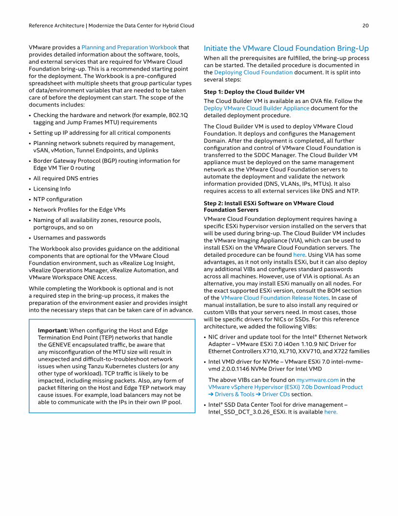
Reference Architecture | Modernize the Data Center for Hybrid Cloud 20
VMware provides a Planning and Preparation Workbook that provides detailed information about the software, tools, and external services that are required for VMware Cloud Foundation bring-up. This is a recommended starting point for the deployment. The Workbook is a pre-configured spreadsheet with multiple sheets that group particular types of data/environment variables that are needed to be taken care of before the deployment can start. The scope of the documents includes:
• Checking the hardware and network (for example, 802.1Q tagging and Jump Frames MTU) requirements
• Setting up IP addressing for all critical components
• Planning network subnets required by management, vSAN, vMotion, Tunnel Endpoints, and Uplinks
• Border Gateway Protocol (BGP) routing information for Edge VM Tier 0 routing
• All required DNS entries
• Licensing Info
• NTP configuration
• Network Profiles for the Edge VMs
• Naming of all availability zones, resource pools, portgroups, and so on
• Usernames and passwords
The Workbook also provides guidance on the additional components that are optional for the VMware Cloud Foundation environment, such as vRealize Log Insight, vRealize Operations Manager, vRealize Automation, and VMware Workspace ONE Access.
While completing the Workbook is optional and is not a required step in the bring-up process, it makes the preparation of the environment easier and provides insight into the necessary steps that can be taken care of in advance.
Important: When configuring the Host and Edge Termination End Point (TEP) networks that handle the GENEVE encapsulated traffic, be aware that any misconfiguration of the MTU size will result in unexpected and difficult-to-troubleshoot network issues when using Tanzu Kubernetes clusters (or any other type of workload). TCP traffic is likely to be impacted, including missing packets. Also, any form of packet filtering on the Host and Edge TEP network may cause issues. For example, load balancers may not be able to communicate with the IPs in their own IP pool.
Initiate the VMware Cloud Foundation Bring-Up When all the prerequisites are fulfilled, the bring-up process can be started. The detailed procedure is documented in the Deploying Cloud Foundation document. It is split into several steps:
Step 1: Deploy the Cloud Builder VMThe Cloud Builder VM is available as an OVA file. Follow the Deploy VMware Cloud Builder Appliance document for the detailed deployment procedure.
The Cloud Builder VM is used to deploy VMware Cloud Foundation. It deploys and configures the Management Domain. After the deployment is completed, all further configuration and control of VMware Cloud Foundation is transferred to the SDDC Manager. The Cloud Builder VM appliance must be deployed on the same management network as the VMware Cloud Foundation servers to automate the deployment and validate the network information provided (DNS, VLANs, IPs, MTUs). It also requires access to all external services like DNS and NTP.
Step 2: Install ESXi Software on VMware Cloud Foundation ServersVMware Cloud Foundation deployment requires having a specific ESXi hypervisor version installed on the servers that will be used during bring-up. The Cloud Builder VM includes the VMware Imaging Appliance (VIA), which can be used to install ESXi on the VMware Cloud Foundation servers. The detailed procedure can be found here. Using VIA has some advantages, as it not only installs ESXi, but it can also deploy any additional VIBs and configures standard passwords across all machines. However, use of VIA is optional. As an alternative, you may install ESXi manually on all nodes. For the exact supported ESXi version, consult the BOM section of the VMware Cloud Foundation Release Notes. In case of manual installation, be sure to also install any required or custom VIBs that your servers need. In most cases, those will be specific drivers for NICs or SSDs. For this reference architecture, we added the following VIBs:
• NIC driver and update tool for the Intel® Ethernet Network Adapter – VMware ESXi 7.0 i40en 1.10.9 NIC Driver for Ethernet Controllers X710, XL710, XXV710, and X722 families
• Intel VMD driver for NVMe – VMware ESXi 7.0 intel-nvme-vmd 2.0.0.1146 NVMe Driver for Intel VMD
The above VIBs can be found on my.vmware.com in the VMware vSphere Hypervisor (ESXi) 7.0b Download Product ➔ Drivers & Tools ➔ Driver CDs section.
• Intel® SSD Data Center Tool for drive management – Intel_SSD_DCT_3.0.26_ESXi. It is available here.

Reference Architecture | Modernize the Data Center for Hybrid Cloud 21
Step 3: Download and Complete the Deployment Parameter Sheet for VMware Cloud FoundationThe Deployment Parameter Sheet is a spreadsheet file that provides the Cloud Builder VM with all the information required for bring-up. It’s a separate file that needs to be downloaded from vmware.com, from the same place where the Cloud Builder VM OVA file was located. You should use the information in the Planning and Preparation Workbook to fill out the Deployment Parameter Sheet. After completing all the required variables, you will import this file during the VMware Cloud Foundation bring-up process.
Full documentation of the Deployment Parameter Sheet is available in the VMware Cloud Foundation Architecture and Deployment Guide Download and Complete Deployment Parameter Sheet. The documentation details all the tabs and fields included in the Deployment Parameter Sheet.
Step 4: VMware Cloud Foundation Bring-upWhen you have ESXi installed on all management nodes, added all needed custom VIBs, and completed the Deployment Parameter Sheet, you can begin the VMware Cloud Foundation bring-up.
The complete description of the VMware Cloud Foundation bring-up process is included in VMware’s Initiate the Cloud Foundation Bring-Up Process documentation.
The bring-up process deploys SDDC Manager, vCenter Server for the Management Domain, NSX-T Management Domain, NSX-T Edge VMs, and vSAN—that is, the complete Management Domain of VMware Cloud Foundation. The process takes about two hours. After the bring-up process is complete, you should see a notification with a link to the new SDDC Manager web interface. The SDDC Manager interface is accessible through a standard web browser.
Important: When the deployment of the Management Domain is completed, be sure to log on to SDDC Manager and provide credentials to your VMware account in the Administration ➔ Repository Settings section, so that SDDC Manager can start syncing against the VMware repository for any available software bundles.
Bring-up Process SummaryThe Management Domain is now created and contains all the components needed to manage the infrastructure. You should not deploy any user applications on this management cluster. Instead, create one or more Workload Domains that comprise separate vSphere clusters with vSAN and NSX-T Data Center preinstalled and configured, along with an additional, dedicated instance of vCenter Server for each such domain. Starting from VMware Cloud Foundation 4.0, when you create a VI Workload Domain, you can choose to either deploy a new NSX-T Manager cluster for the Workload Domain, or to share an existing NSX-T Manager cluster that was previously created for another VI Workload Domain. Any new instances of vCenter Server (one per each Workload Domain) and an NSX-T Manager cluster (if needed) will be deployed on the Management Domain.
VMware Cloud Foundation Workload Domain DeploymentDeployment and configuration of Workload Domains is performed using SDDC Manager. The process is split into three steps. The first step includes commissioning of the ESXi hosts that will be used for the cluster and configuring initial components (such as vSAN and the NSX-T Management Domain). In the second step, the NSX-T Edge cluster is deployed onto the created domain to enable two-tier routing for north-south traffic. The third and final step deploys the necessary Kubernetes services.
The detailed procedure for a complete Workload Domain setup is available in the “Start the VI Configuration Wizard” section of the VMware Cloud Foundation Operations and Administration Guide.
Similar to the Management Domain, Workload Domain creation requires multiple network IPs, DNS entries, services, and BGP routing information to be available. The BGP neighbor configuration on the L3 switches, which will later have a BGP peering with the Workload Domain’s T0 router, must be done prior to the Workload Domain deployment. See the detailed prerequisites here. However, you may share the existing Host TEP and Edge TEP subnet across Management and Workload Domains, which simplifies the configuration.
Step 1: Commissioning Hosts and Creating a VI Workload DomainCreating a new Workload Domain on VMware Cloud Foundation is controlled and orchestrated by SDDC Manager, which installs and configures all the needed components (including vCenter Server, vSAN, and NSX-T Data Center). To deploy the new Workload Domain, a sufficient number of ESXi hosts must be available in SDDC Manager. Adding new hosts to SDDC Manager is called commissioning. See the “Commission Hosts” section of the official documentation for the detailed procedure.
Once hosts are commissioned, use the VI Configuration Wizard to start the Workload Domain deployment; see Start the VI Configuration Wizard for detailed instructions.
Step 2: Deploying an NSX-T Edge Cluster to the Workload DomainBy default, all new Workload Domains do not include any NSX-T Edge clusters and are isolated from a network perspective. An NSX-T Edge Cluster needs to be deployed to provide routing and network services.
The procedure is quite complex and requires a similar level of data and preparation as the initial deployment of the Management Domain. You will need to configure the network layout similar to what can be seen in Figure 19 on the next page. Follow the official instructions in VMware’s Deploying NSX-T Edge Clusters documentation. The deployment process is started on SDDC Manager and is fully automated after providing the complete data, so the risk of error is greatly reduced, compared to the manual configuration process in VMware Cloud Foundation 3.9 and earlier.

Reference Architecture | Modernize the Data Center for Hybrid Cloud 22
Physical Layer 3 Devices
NSX-TEdge Cluster
Edge VM1
Segment 1 - 192.168.11.0/24 Segment 2 - 192.168.31.0/24
Edge VM2
VM VM VM
Tier-0 Gateway Active/Active
Tier-1 Gateway
VM VM VM
vLANs
Tier-1 to Tier-0 Connection
Segment
ECMP
Figure 19. Sample two-node NSX-T Edge cluster in a single rack. All endpoints, ASNs, and DNS entries need to be provided by the user for the automatic deployment process. Source: https://docs.vmware.com/en/VMware-Cloud-Foundation/4.0/com.vmware.vcf.admin.doc_40/GUID-D17D0274-7764-43BD-8252-D9333CA7415A.html
Step 3: Deploying the Necessary Kubernetes ServicesStep 3 of Workload Domain deployment is a three-step process in itself and is described in the next section.
Enabling vSphere with Tanzu (Creating the Supervisor Cluster)To create a Kubernetes control plane inside the hypervisor layer, it is necessary to enable vSphere with Kubernetes on the Workload Domain cluster. This control plane is called the Supervisor Cluster and contains specific objects that enable the capability to run Kubernetes workloads within ESXi. Once this is done, the TKG Service (self-service lifecycle management of Tanzu Kubernetes cluster) is used to create and manage a Tanzu Kubernetes clusters within the Supervisor Cluster. This is done in a declarative manner, similar to the standard Kubernetes process that operators and developers are familiar with.
To configure vSphere with Tanzu on a vSphere cluster, the environment must meet specific networking and infrastructure requirements. There are multiple areas that need to be addressed; consult the System Requirements and Topologies for Setting Up a Supervisor Cluster with NSX-T Data Center document for details. Because the Workload Domain cluster was created automatically as part of VMware Cloud Foundation, most requirements are already met.
With Kubernetes workload management, you validate the underlying infrastructure for vSphere with Tanzu and then complete the deployment in vSphere. The first step is performed using SDDC Manager, the second step is executed from vCenter. The entire process is described in the Deploy Workload Management document.
Step 3.1: Kubernetes Workload Management Environment ValidationThis step checks the environment compatibility for Kubernetes workload management. You must provide a cluster with a working NSX-T Edge Cluster as well as DNS and NTP servers. Validations that will be performed include vCenter, Network, and Kubernetes workload management compatibility, including a check for licenses: a proper “vSphere with Tanzu” license must be applied to all hosts in the cluster. After a successful environment validation, you will be presented with a “Complete in vSphere” button that will redirect you to the Kubernetes Workload Management page in the vSphere user interface. By default, the vSphere Center for the VI Workload Domain where the Kubernetes workload management is to be deployed is selected.
Step 3.2: Deploy the Supervisor ClusterNow that the environment is validated for Supervisor Cluster use, it can be deployed. This is accomplished from the vCenter -> Workload Management menu selection. Apart from the input data provided in the validation step, you must also provide several IP addresses and subnets: five IPs for the Kubernetes control plane VMs, non-routable Pod and Service subnets, and routable Ingress and Egress subnets.
Important: Despite the Pod and Service subnets being non-routable by design in Kubernetes, Intel’s experience is that they are advertised by the T0 router using the default settings from the deployment procedure. Because of this, be sure to use different Pod and Service subnets for each Supervisor Cluster if you plan to have more than one (for example, having two Workload Domains, each with Kubernetes enabled).
You can also choose storage policies for placement of various components of the Kubernetes environment: control plane VMs, vSphere Pods, and cache for container images. The detailed procedure is available in the Configure the Workload Platform with NSX-T Data Center as the Networking Stack document.
Step 3.3: Deploy the Tanzu Kubernetes ClusterA Tanzu Kubernetes cluster is a distribution of the open-source Kubernetes container orchestration platform that is signed and supported by VMware. It can be provisioned on the Supervisor Cluster by using the TKG Service declarative API using the kubectl command-line interface and a cluster specification defined in YAML. The complete documentation on how to deploy and use Tanzu Kubernetes clusters is available in the Running Tanzu Kubernetes Clusters in vSphere with Tanzu document.
To use the TKG Service, a Supervisor Namespace must be created; refer to the details provided in the Create and Configure a Supervisor Namespace document. You may optionally enable a Private Image Registry (Harbor) that will be used by the Supervisor Cluster. You create it

Reference Architecture | Modernize the Data Center for Hybrid Cloud 23
from the vSphere client. Follow the Enable a Private Image Registry guide for details. You may deploy Pods, Services, and Deployments on the Supervisor Cluster; however, bear in mind that this cluster’s intended usage is for administering the Kubernetes environment. It is advised that tenant workloads be run on guest Tanzu Kubernetes clusters.
Important: VMware recommends using a tagged based storage policy for the Supervisor Namespace. Please follow the Create Storage Policies for vSphere with Tanzu guide to set the required storage policies for vSphere with Tanzu before creating the Supervisor Namespace.
Once the Namespace is created, you will have to Create a Subscribed Content Library for the OVA files used to create Tanzu Kubernetes clusters, install Kubernetes CLI Tools for vSphere, connect to the Supervisor Cluster to define specifications for a Tanzu Kubernetes cluster, create configuration YAMLs (see the example files and complete list of parameters guides), and finally provision the Tanzu Kubernetes cluster.
Follow the entire workflow with details using the Create Tanzu Kubernetes Clusters document. It includes step-by-step instructions for all the tasks mentioned above, along with the necessary links.
All Tanzu Kubernetes clusters that are provisioned by the TKG Service have the PodSecurityPolicy Admission Controller enabled. This means that a pod security policy is required to deploy workloads. There are two default pod security policies out-of-the-box, but you can create your own. To create Deployments, StatefulSets, and DaemonSets in the default namespace, a binding to one of the Pod Security Policies needs to be created. Follow the Using Pod Security Policies with Tanzu Kubernetes Cluster document for the necessary steps.
To learn more about how to deploy workloads, read the Deploying Workloads to Tanzu Kubernetes Clusters guide.
This concludes the environment setup. If you need to deploy multiple Workload Domains with Kubernetes, repeat the above steps starting from the VMware Cloud Foundation Workload Domain Deployment.
VMware Cloud on AWS ConfigurationThis section describes the components and steps needed to bring up VMware Cloud on AWS and connect it to the on-premises environment.
Creation of SDDC ManagerThe first step to bring up the cloud environment is to deploy an SDDC from the VMware Cloud console. This process is simple and requires selecting an AWS region where the service should be located and choosing deployment options (one or more hosts within the SDDC with the option of a stretched cluster), host type, and name of the SDDC. You also must connect the newly created SDDC to an AWS account (within 14 days). The entire process is explained in detail in the Deploy an SDDC from the VMC Console document. After finishing the entire process, you will have a complete vCenter environment with a compute cluster ready. Be sure to add the necessary firewall rules in the VMware Cloud Console SDDC settings after deployment; by default, all traffic is blocked, and you won’t be able to use your SDDC environment without changing these rules.
VPN ConfigurationA dedicated connection is needed to access an SDDC securely from the on-premises services. Achieve this by establishing a VPN connection or by using AWS Direct Connect (DX). In this reference architecture, we configured a site-to-site IPsec VPN. The process is relatively easy to configure from the SDDC side, but detailed planning and pre-configuration are usually needed on the on-premises side. Each environment is different and will require additional configuration to prepare the tunnel endpoint, routing, and firewall rules. The type of the on-premises tunnel endpoint defines the exact settings that need to be set for the tunnel to be established, and both ends of the tunnel must match. In our case, we used a policy-based VPN, but depending on your personal needs and environment, you can use a route-based VPN and BGP instead. End users can also connect to VMware Cloud on AWS without a VPN, but it is less secure than having a VPN or DX in place as a prerequisite to using some of the more advanced features that come with hybrid/multicloud.
For step-by-step VPN configuration information, read the VMware Cloud on AWS: Connecting with VPN article and the Configure a VPN Connection Between Your SDDC and On-Premises Data Center Procedure on VMware Docs.
Hybrid Linked Mode EnablementFor ease of manageability, the Hybrid Linked Mode can be configured. It enables administration of both on-premises and cloud vCenter with single sign-on. It also centralizes the management into one place: an additional on-premises VM appliance from which the entire infrastructure is visible, as if connected to a single platform service controller. Detailed deployment information is available in Configuring Hybrid Linked Mode on VMware Docs.
Important: You must configure the VPN before the Hybrid Linked Mode because it is required that the cloud vCenter is reachable using its internal (non-public) cloud IP address, which is possible only when the VPN is configured.

Reference Architecture | Modernize the Data Center for Hybrid Cloud 24
SummaryWith the need for high-performance data analytics and AI on the rise, enterprises seek flexible solutions that can run workloads on-premises or in the public cloud. The VMware hybrid/multicloud platform combines the best of Intel hardware and VMware virtualization software. With this end-to-end solution that is ready to deploy, enterprises are poised to run both their traditional data analytics workloads and the AI and machine-learning workloads of the future.
This reference architecture has been validated to meet expected key performance indicators in demanding customer workload scenarios for VMware Cloud Foundation 4.0, which can take advantage of Intel DL Boost and VNNI. Intel testing shows that organizations deploying this reference architecture can expect the following:13
• Upgrading from an older version of VMWare Cloud Foundation (such as 3.9) to version 4.x provides up to 1.64x improvement for the Plus configuration.
• Using Intel DL Boost and VNNI with int8 precision quadruples performance over fp32 precision.
• Using an Intel architecture-optimized version of TensorFlow more than doubled the performance of the ResNet 50 v1.5 topology compared to the default version of TensorFlow.
These results strongly illustrate that the right combination of software and hardware—and software that is optimized for the hardware—can substantially increase application performance. And the faster your applications run, the faster your business runs.
Find the solution that is right for your organization. Contact your Intel representative or visit the Intel and VMware Partnership website.
Learn MoreYou may find the following resources helpful:
• Intel® Data Center Blocks for Cloud – vSAN ReadyNodes• Intel® Optane™ Persistent Memory • Intel Optane Persistent Memory – Virtualized Performance Study• 2nd Generation Intel® Xeon® Scalable processors• Intel® Select Solutions for VMware vSAN ReadyNodes• Intel® Optane™ Solid State Drives• Intel® Solid State Drives Data Center Family• Intel® Deep Learning Boost• Intel® Distribution of OpenVINO™ toolkit• Intel® Framework Optimizations• VMware Cloud Foundation• VMware vSAN• VMware Cloud on AWS• VMware Tanzu

Reference Architecture | Modernize the Data Center for Hybrid Cloud 25
Appendix A: Solution Features Validation and BenchmarkingThis section contains information on how to reproduce feature validation experiments, including installation of some required components and software procedures, configuration instructions, and benchmark execution scripts.
Running the TensorFlow Benchmark with an Intel® architecture-optimized container stack (Inference Benchmarks Reproduction)You first need to use SSH to connect to a node or VM in your VMware environment. Then follow these steps:
1. Install Docker2. Prepare the benchmark.sh file with the following content:
#!/bin/bashset -euo pipefail
if [ $# -ne 4 ]then echo “Insufficient arguments provided” echo “Usage: ./benchmark.sh [TOPOLOGY_NAME] [PRECISION] [BATCH_SIZE]” echo “Example usage: ./benchmark.sh resnet50v1_5 int8 1” echo “Example usage: ./benchmark.sh inceptionv3 fp32 16” exit 1fi
IN_GRAPH=‘‘MODEL_NAME=“$1“PRECISION=”$2”BATCH_SIZE=”$3”
if [[ “${MODEL_NAME}” == “resnet50v1_5” ]] && [[ “${PRECISION}” == “int8” ]]then IN_GRAPH=”/tf/resnet50v1_5_int8_pretrained_model.pb”elif [[ “${MODEL_NAME}” == “resnet50v1_5” ]] && [[ “${PRECISION}” == “fp32” ]]then IN_GRAPH=”/tf/resnet50_v1.pb”elif [[ “${MODEL_NAME}” == “inceptionv3” ]] && [[ “${PRECISION}” == “int8” ]]then IN_GRAPH=”/tf/inceptionv3_int8_pretrained_model.pb”elif [[ “${MODEL_NAME}” == “inceptionv3” ]] && [[ “${PRECISION}” == “fp32” ]]then IN_GRAPH=”/tf/inceptionv3_fp32_pretrained_model.pb”else echo “Bad arguments”fi
echo “model_name,batch_size,fps,latency_ms”
benchmark_app_output=”$(python3 /tf/intel-models/benchmarks/launch_benchmark.py --in-graph ${IN_GRAPH} --model-name ${MODEL_NAME} --framework tensorflow --precision ${PRECISION} --mode inference --batch-size ${BATCH_SIZE} --benchmark-only 2>&1)”latency=”$(echo $benchmark_app_output | sed -n ‘s/.*Latency: \([0-9]*\.[0-9]*\) ms.*/\1/p’)”if [[ -z “${latency}” ]]; then latency=’-1’fifps=”$(echo $benchmark_app_output | sed -n ‘s/.*[T,t]hroughput.*: \([0-9]*\.[0-9]*\) images\/sec.*/\1/p’)”if [[ -z “${fps}” ]]; then fps=’-1’fiecho “${MODEL_NAME}_${PRECISION},${BATCH_SIZE},${fps},${latency}”
3. Prepare a Dockerfile (dlrs.Dockerfile) with the following content:
FROM clearlinux/stacks-dlrs-mkl:v0.5.0
RUN mkdir /tf && cd /tfRUN swupd clean && swupd bundle-add wget git devpkg-gperftools sysadmin-basicRUN git clone --depth 1 https://github.com/tensorflow/models.git /tf/tf_modelsRUN git clone -b v1.5.0 --depth 1 https://github.com/IntelAI/models.git /tf/intel-modelsRUN wget -q -P /tf https://storage.googleapis.com/intel-optimized-tensorflow/models/v1_5/resnet50v1_5_int8_pretrained_model.pbRUN wget -q -P /tf https://zenodo.org/record/2535873/files/resnet50_v1.pbRUN wget -q -P /tf https://storage.googleapis.com/intel-optimized-tensorflow/models/v1_5/inceptionv3_int8_pretrained_model.pbRUN wget -q -P /tf https://storage.googleapis.com/intel-optimized-tensorflow/models/v1_5/inceptionv3_fp32_pretrained_model.pbCOPY ./benchmark.sh /tfRUN chmod +x /tf/benchmark.sh
WORKDIR /tfENTRYPOINT [“/tf/benchmark.sh”]CMD [“resnet50v1_5”, “int8”, “1”]
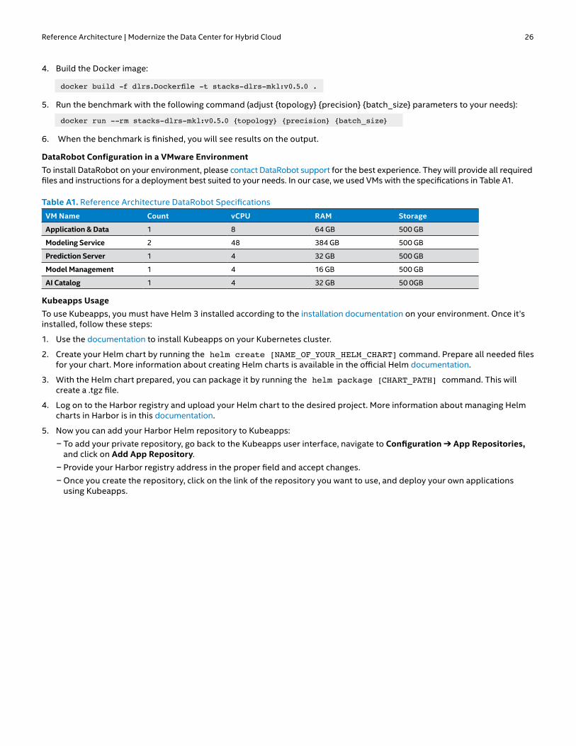
Reference Architecture | Modernize the Data Center for Hybrid Cloud 26
4. Build the Docker image:
docker build -f dlrs.Dockerfile -t stacks-dlrs-mkl:v0.5.0 .
5. Run the benchmark with the following command (adjust {topology} {precision} {batch_size} parameters to your needs):
docker run --rm stacks-dlrs-mkl:v0.5.0 {topology} {precision} {batch_size}
6. When the benchmark is finished, you will see results on the output.
DataRobot Configuration in a VMware EnvironmentTo install DataRobot on your environment, please contact DataRobot support for the best experience. They will provide all required files and instructions for a deployment best suited to your needs. In our case, we used VMs with the specifications in Table A1.
Table A1. Reference Architecture DataRobot Specifications
VM Name Count vCPU RAM Storage
Application & Data 1 8 64 GB 500 GB
Modeling Service 2 48 384 GB 500 GB
Prediction Server 1 4 32 GB 500 GB
Model Management 1 4 16 GB 500 GB
AI Catalog 1 4 32 GB 50 0GB
Kubeapps UsageTo use Kubeapps, you must have Helm 3 installed according to the installation documentation on your environment. Once it’s installed, follow these steps:
1. Use the documentation to install Kubeapps on your Kubernetes cluster.
2. Create your Helm chart by running the helm create [NAME_OF_YOUR_HELM_CHART] command. Prepare all needed files for your chart. More information about creating Helm charts is available in the official Helm documentation.
3. With the Helm chart prepared, you can package it by running the helm package [CHART_PATH] command. This will create a .tgz file.
4. Log on to the Harbor registry and upload your Helm chart to the desired project. More information about managing Helm charts in Harbor is in this documentation.
5. Now you can add your Harbor Helm repository to Kubeapps:
n To add your private repository, go back to the Kubeapps user interface, navigate to Configuration ➔ App Repositories, and click on Add App Repository.
n Provide your Harbor registry address in the proper field and accept changes.
n Once you create the repository, click on the link of the repository you want to use, and deploy your own applications using Kubeapps.

Reference Architecture | Modernize the Data Center for Hybrid Cloud 27
Solution Provided by:
Intel technologies may require enabled hardware, software or service activation. No product or component can be absolutely secure. Your costs and results may vary. Software and workloads used in performance tests may have been optimized for performance only on Intel microprocessors. Performance tests, such as SYSmark and MobileMark, are
measured using specific computer systems, components, software, operations and functions. Any change to any of those factors may cause the results to vary. You should consult other information and performance tests to assist you in fully evaluating your contemplated purchases, including the performance of that product when combined with other products. For more complete information visit intel.com/benchmarks.
Intel’s compilers may or may not optimize to the same degree for non-Intel microprocessors for optimizations that are not unique to Intel microprocessors. These optimizations include SSE2, SSE3, and SSSE3 instruction sets and other optimizations. Intel does not guarantee the availability, functionality, or effectiveness of any optimization on microprocessors not manufactured by Intel. Microprocessor-dependent optimizations in this product are intended for use with Intel microprocessors. Certain optimizations not specific to Intel microarchitecture are reserved for Intel microprocessors. Please refer to the applicable product User and Reference Guides for more information regarding the specific instruction sets covered by this notice.
Performance results are based on testing as of dates shown in configurations and may not reflect all publicly available updates. See backup for configuration details. Intel does not control or audit third-party data. You should consult other sources to evaluate accuracy. The products described may contain design defects or errors known as errata which may cause the product to deviate from published specifications. Current characterized errata are
available on request. Intel, the Intel logo, and other Intel marks are trademarks of Intel Corporation in the U.S. and/or other countries. Other names and brands may be claimed as the property of others. © Intel Corporation 1020/SALL/KC/PDF 343960-001US
1 According to the VMware Cloud Foundation 4.0.1 release notes, HCX is not officially supported on VMware Cloud Foundation 4.0.1. VMware states that it plans to add HCX support in the future.2 This result was reported by an independent test/benchmark published at glesys.se/blogg/benchmarking-intel-optane-dc-persistent-memory,
(In the report cited, table 3 measured latency in microseconds with 512-byte block size.).3 Testing by Intel, August-September 2020. Each cluster (Base, Plus, and the Management cluster that was used for workload generation) consists of four machines. All machines are
identical within the given cluster. Base 4-node cluster configuration: Intel® Xeon® Gold 6248 processor (2.5 GHz, 20 cores); 384 GB DRAM (12x 32 GB 2933 MHz); Intel® Hyper-Threading Technology ON; Intel® Turbo Boost
Technology ON; Storage: VMware vSAN, disk group: 1x Intel® Optane™ SSD DC P4800X 375 GB and 2x Intel® SSD DC P4510 2 TB, two disk groups per node; BIOS = 02.01.0010; microcode = 0x0500002c; OS = VMware ESXi 7.0b 16386292; 1x Intel® Ethernet Adapter XXV710-DA2.
Plus 4-node cluster configuration: Intel® Xeon® Platinum 8268 processor (2.9 GHz, 24 cores); 384 GB DRAM (12x 32 GB 2933 MHz) plus 1,536 GB Intel® Optane™ persistent memory (12x 128 GB); Intel Hyper-Threading Technology ON; Intel Turbo Boost Technology ON; Storage: VMware vSAN, disk group: 1x Intel Optane SSD DC P4800X 375 GB and 3x Intel SSD DC P4510 2 TB, two disk groups per node; BIOS = 02.01.0010; microcode = 0x0500002c; OS = VMware ESXi 7.0b 16386292; 1x Intel Ethernet Adapter XXV710-DA2; PMem used a 2-2-2 configuration in App Direct Mode; PMem firmware version = 01.02.00.5417.
4 Intel® Deep Learning Boost configuration: Tested by Intel as of February 26, 2019. Platform: 2-socket Intel® Xeon® Platinum 9282 processor (56 cores per socket), Intel® Hyper-Threading Technology ON, Intel® Turbo Boost Technology ON, Total Memory 768 GB (24 slots/32 GB/2933 MHz), BIOS: SE5C620.86B.0D.01.0241.112020180249, Centos 7 Kernel 3.10.0-957.5.1.el7. x86_64, Deep Learning Framework: Intel® Optimization for Caffe version: https://github.com/intel/caffe d554cbf1, ICC 2019.2.187, MKL DNN version: v0.17 (commit hash: 830a10059a018cd-2634d94195140cf2d8790a75a), model: https://github.com/intel/caffe/blob/master/models/intel_optimized_models/int8/resnet50_int8_full_conv.prototxt, BS=64, No datalayer DummyData: 3x224x224, 56 instance/2-socket, Datatype: INT8.
Baseline configuration: Tested by Intel as of July 11, 2017: 2S Intel® Xeon® Platinum 8180 processor (28 cores per socket), Intel Hyper-Threading Technology OFF, Intel Turbo Boost Technology OFF, scaling governor set to “performance” via Intel® P-state driver, 384 GB DDR4-2666 ECC RAM. CentOS Linux release 7.3.1611 (Core), Linux kernel 3.10.0-514.10.2.el7.x86_64. SSD: Intel® SSD DC S3700 (800 GB, 2.5in SATA 6Gb/s, 25nm, MLC).Performance measured with: Environment variables: KMP_AFFINITY=’granularity=fine, compact‘, OMP_NUM_THREADS=56, CPU Freq set with cpupower frequency-set -d 2.5G -u 3.8G -g performance. Caffe: (https://github.com/intel/caffe), revision f96b759f71b2281835f690af267158b82b150b5c. Inference measured with “caffe time --forward_only” command, training measured with “caffe time” command. For “ConvNet” topologies, dummy dataset was used. For other topologies, data was stored on local storage and cached in memory before training. Topology specs from https://github.com/intel/caffe/tree/master/models/intel_optimized_models (ResNet-50), Intel C++ compiler ver. 17.0.2 20170213, Intel® Math Kernel Library small libraries version 2018.0.20170425. Caffe run with “numactl -l”.
5 Intel. “Product Brief: Intel Optane SSD DC P4800X/P4801X Series.” intel.com/content/www/us/en/products/docs/memory-storage/solid-state-drives/data-center-ssds/optane-ssd-dc-p4800x-p4801x-brief.html.
6 Intel. “Product Brief: Intel Optane SSD DC P4800X Series.” intel.com/content/www/us/en/solid-state-drives/optane-ssd-dc-p4800x-brief.html. Based on internal Intel testing.7 Intel® QuickAssist Technology, software.intel.com/content/www/us/en/develop/articles/how-intel-quickassist-technology-accelerates-nfv-use-cases.html 8 VMware, Deploy an SDDC from the VMC Console, docs.vmware.com/en/VMware-Cloud-on-AWS/services/com.vmware.vmc-aws.getting-started/GUID-EF198D55-03E3-44D1-AC48-6E2ABA31FF02.html.
Intel deployed VMware Cloud on AWS four times and can confirm that deployment took about two hours each time, based on anecdotal experience.9 VMware NSX AVI load balancer benchmark report: info.avinetworks.com/load-balancer-performance-benchmark-report-vmware10 To learn more, see builders.intel.com/ai/blog/1-billion-models-datarobot-intel.11 Testing by Intel, August 2020. See endnote 3 for hardware configuration. Workload: ResNet 50 v1.5 topology at int8, fp32 precision. Default TensorFlow tensorflow/tensorflow:1.15.0-py3;
optimized TensorFlow: clearlinux/stacks-dlrs-mkl:v0.5.0. Base Fat VM configuration: 80 vCPUs; OS=CentOS Linux release 8.2.2004; kernel=4.18.0-193.14.2.el8_2.x86_64; other SW: VMware Cloud Foundation 4.0.1, VMware ESXi hypervisor 7.0b 16386292. Plus Fat VM configuration: 96 vCPUs; otherwise, identical to the Base Fat VM configuration.12 VMware NSX-T Edge QAT details: docs.vmware.com/en/VMware-NSX-T-Data-Center/3.0/installation/GUID-F807EC0C-3417-4E89-BB90-F2F58AA34ECE.html13 See endnote 11.

![March 2017 Financial Technology (FinTech) and RegulationFinTech Forum, “[b]lockchain technology has the potential to modernize, simplify, or even potentially replace, current](https://img.pdfslide.us/doc/110x75/60c36a43a8838065b15a4af7/march-2017-financial-technology-fintech-and-regulation-fintech-forum-aoeblockchain.jpg)