Embed Size (px)
Citation preview
Mechanics and Mechanical Engineering
Vol. 15, No. 3 (2011) 289–296
c⃝ Technical University of Lodz
Modernization of a Nitrous GasTurbine–Driven Turbocompressor
W ladys law Kry l lowiczZbigniew Kozanecki
Institute of TurbomachineryTechnical University of Lodz
Piotr Swider
Neo–Tec sp. z o.opiotr.swider@neo–tec.pl
Received (18 August 2011)
Revised (20 September 2011)
Accepted (28 September 2011)
The modernization of a nitrous gas four–stage centrifugal compressor is presented. Theassumptions for modernization, its methodology and the results of thermodynamical,flow and dynamical calculations have been discussed. The technological aspects of therotor modernization have been given.
Keywords: Nitrous gas, compressor, modernization, stability, rotordynamics
1. Introduction
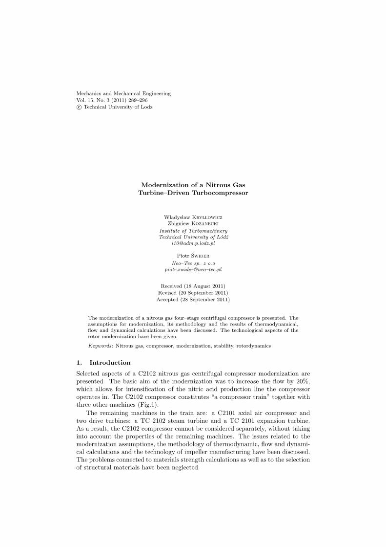
Selected aspects of a C2102 nitrous gas centrifugal compressor modernization arepresented. The basic aim of the modernization was to increase the flow by 20%,which allows for intensification of the nitric acid production line the compressoroperates in. The C2102 compressor constitutes “a compressor train” together withthree other machines (Fig.1).
The remaining machines in the train are: a C2101 axial air compressor andtwo drive turbines: a TC 2102 steam turbine and a TC 2101 expansion turbine.As a result, the C2102 compressor cannot be considered separately, without takinginto account the properties of the remaining machines. The issues related to themodernization assumptions, the methodology of thermodynamic, flow and dynami-cal calculations and the technology of impeller manufacturing have been discussed.The problems connected to materials strength calculations as well as to the selectionof structural materials have been neglected.
290 Kry l lowicz, W., Kozanecki, Z., Swider, P.
TC 2102 steam
turbine
C2101 axial air
compressorC2102 nitrous
gas compressor
TC 2101 turbine
Figure 1 General arrangement of the ”compressor train”
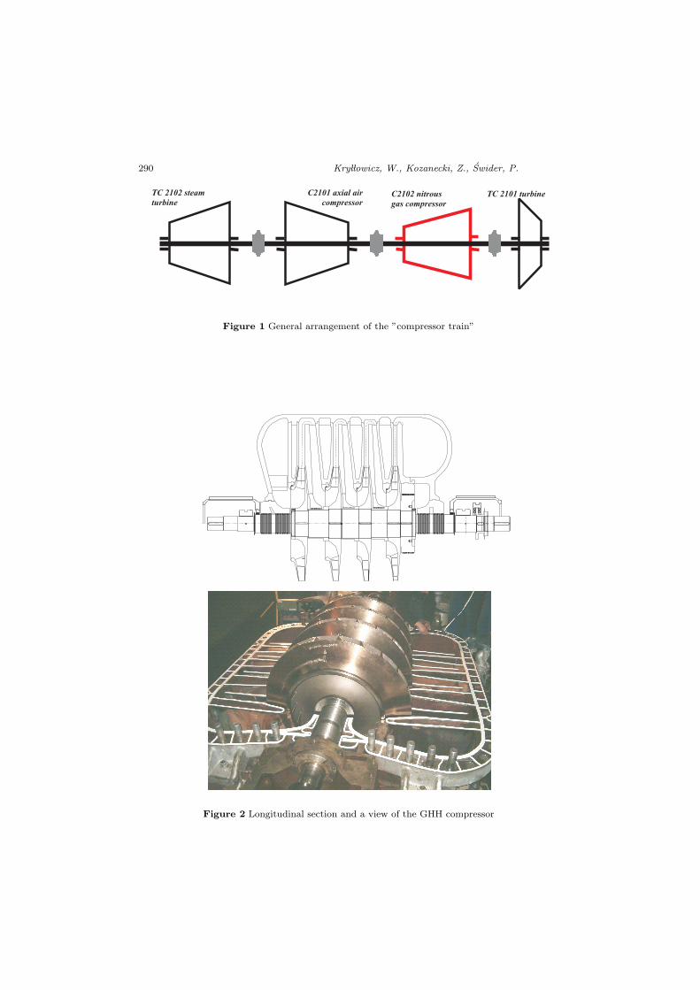
Figure 2 Longitudinal section and a view of the GHH compressor
Modernization of a Nitrous Gas Turbine ... 291
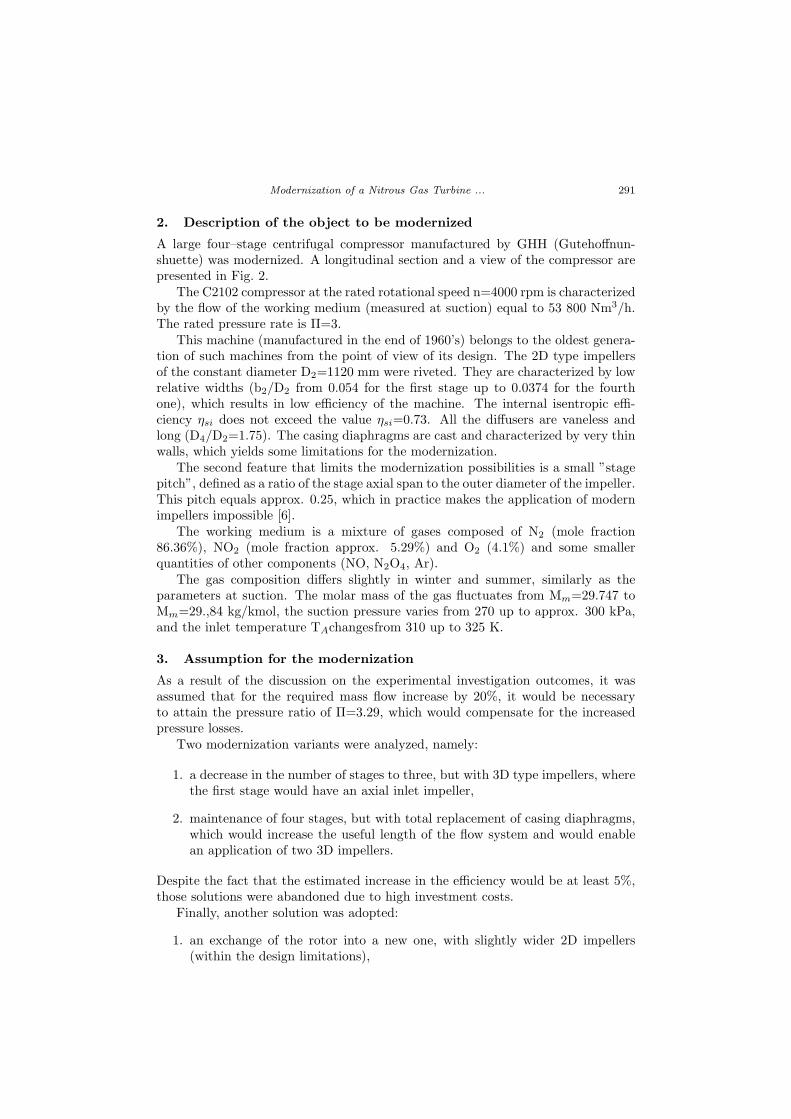
2. Description of the object to be modernized
A large four–stage centrifugal compressor manufactured by GHH (Gutehoffnun-shuette) was modernized. A longitudinal section and a view of the compressor arepresented in Fig. 2.
The C2102 compressor at the rated rotational speed n=4000 rpm is characterizedby the flow of the working medium (measured at suction) equal to 53 800 Nm3/h.The rated pressure rate is Π=3.
This machine (manufactured in the end of 1960’s) belongs to the oldest genera-tion of such machines from the point of view of its design. The 2D type impellersof the constant diameter D2=1120 mm were riveted. They are characterized by lowrelative widths (b2/D2 from 0.054 for the first stage up to 0.0374 for the fourthone), which results in low efficiency of the machine. The internal isentropic effi-ciency ηsi does not exceed the value ηsi=0.73. All the diffusers are vaneless andlong (D4/D2=1.75). The casing diaphragms are cast and characterized by very thinwalls, which yields some limitations for the modernization.
The second feature that limits the modernization possibilities is a small ”stagepitch”, defined as a ratio of the stage axial span to the outer diameter of the impeller.This pitch equals approx. 0.25, which in practice makes the application of modernimpellers impossible [6].
The working medium is a mixture of gases composed of N2 (mole fraction86.36%), NO2 (mole fraction approx. 5.29%) and O2 (4.1%) and some smallerquantities of other components (NO, N2O4, Ar).
The gas composition differs slightly in winter and summer, similarly as theparameters at suction. The molar mass of the gas fluctuates from Mm=29.747 toMm=29.,84 kg/kmol, the suction pressure varies from 270 up to approx. 300 kPa,and the inlet temperature TAchangesfrom 310 up to 325 K.
3. Assumption for the modernization
As a result of the discussion on the experimental investigation outcomes, it wasassumed that for the required mass flow increase by 20%, it would be necessaryto attain the pressure ratio of Π=3.29, which would compensate for the increasedpressure losses.
Two modernization variants were analyzed, namely:
1. a decrease in the number of stages to three, but with 3D type impellers, wherethe first stage would have an axial inlet impeller,
2. maintenance of four stages, but with total replacement of casing diaphragms,which would increase the useful length of the flow system and would enablean application of two 3D impellers.
Despite the fact that the estimated increase in the efficiency would be at least 5%,those solutions were abandoned due to high investment costs.
Finally, another solution was adopted:
1. an exchange of the rotor into a new one, with slightly wider 2D impellers(within the design limitations),
292 Kry l lowicz, W., Kozanecki, Z., Swider, P.
2. the required flow increase would be divided into the following proportions:5% (design alternations) and 15% (an increase in the rotational speed from4000 to 4200 rpm).
These assumptions are followed by the necessity to:
1. adapt the steam and expansion turbine to continuous operation under in-creased rotations and higher power consumption,
2. analyze the dynamics of the new rotor in detail and to introduce the requiredalternations in the bearing system.
4. Calculation methodology and characteristics of the modernized flowsystem
Owing to simplicity of the flow system, a 1D calculation method was applied inthe calculations, and the idea of CFD computations was abandoned. A standardcalculation package used at the Institute of Turbomachinery, TUL, was used.
The working gas properties were determined on the basis of the Berthelot equa-tions of state. An interesting calculation problem consists in taking into accountthe specific reaction that occurs inside the flow system [7].
At the temperature under 147˚C (420 K), gaseous nitrogen tetroxide originatesspontaneously from nitrogen dioxide NO2, according to the scheme:
2NO2=N2O4+61.45kJ. At the temperature above 147˚C, N2O4 exists only intrace quantities, and the reaction of particle breakdown of N2O4 into two particlesof NO2 is endothermic (this effect causes a drop in the mole fraction of N2O4 from0.97% at suction to 0. 01% at discharge in the C2102 compressor). However, dueto a small mole fraction of N2O4, the actual temperature drop is imperceptible inpractice.
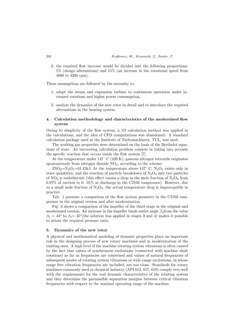
Tab. 1 presents a comparison of the flow system geometry in the C2102 com-pressor in the original version and after modernization.
Fig. 3 shows a comparison of the impeller of the third stage in the original andmodernized version. An increase in the impeller blade outlet angle β2from the valueβ2 = 44o to β2= 45o(the solution was applied in stages 3 and 4) makes it possibleto attain the required pressure ratio.
5. Dynamics of the new rotor
A physical and mathematical modeling of dynamic properties plays an importantrole in the designing process of new rotary machines and in modernization of theexisting ones. A high level of the machine rotating system vibrations is often causedby the fact that values of synchronous excitations (connected with machine shaftrotations) as far as frequencies are concerned and values of natural frequencies ofsubsequent modes of rotating system vibrations or wide-range excitations, in whoserange free vibration frequencies are included, are too close. Standards for rotarymachines commonly used in chemical industry (API 612, 617, 610) comply very wellwith the requirements for the real dynamic characteristics of the rotating systemand they determine the permissible separation margins between critical vibrationfrequencies with respect to the nominal operating range of the machine.
Modernization of a Nitrous Gas Turbine ... 293
Table 1 Comparison of the geometry before and after modernization
No. Value Symbol - 1ststage
2ndstage
3rdstage
4thstage
1Impeller outerdiameter
D2 - 1120 1120 1120 1120
2 Outlet blade b2new 67.5 53.3 47.52 43.5
width original 63.5 50.5 45.00 41.2
3 Blade outlet β∗2
new 50 48 45 42angle original 50 48 44 39
4 Impeller eye D0Z
new 674.5 652.7 632.0 611.0diameter original 660 640 620 600
5 Blade inlet dia– D1new 693.5 662 646 620
meter (average) original 705 669 648 621
Figure 3 Comparison of the impeller of the third stage in the original and modernized version
294 Kry l lowicz, W., Kozanecki, Z., Swider, P.
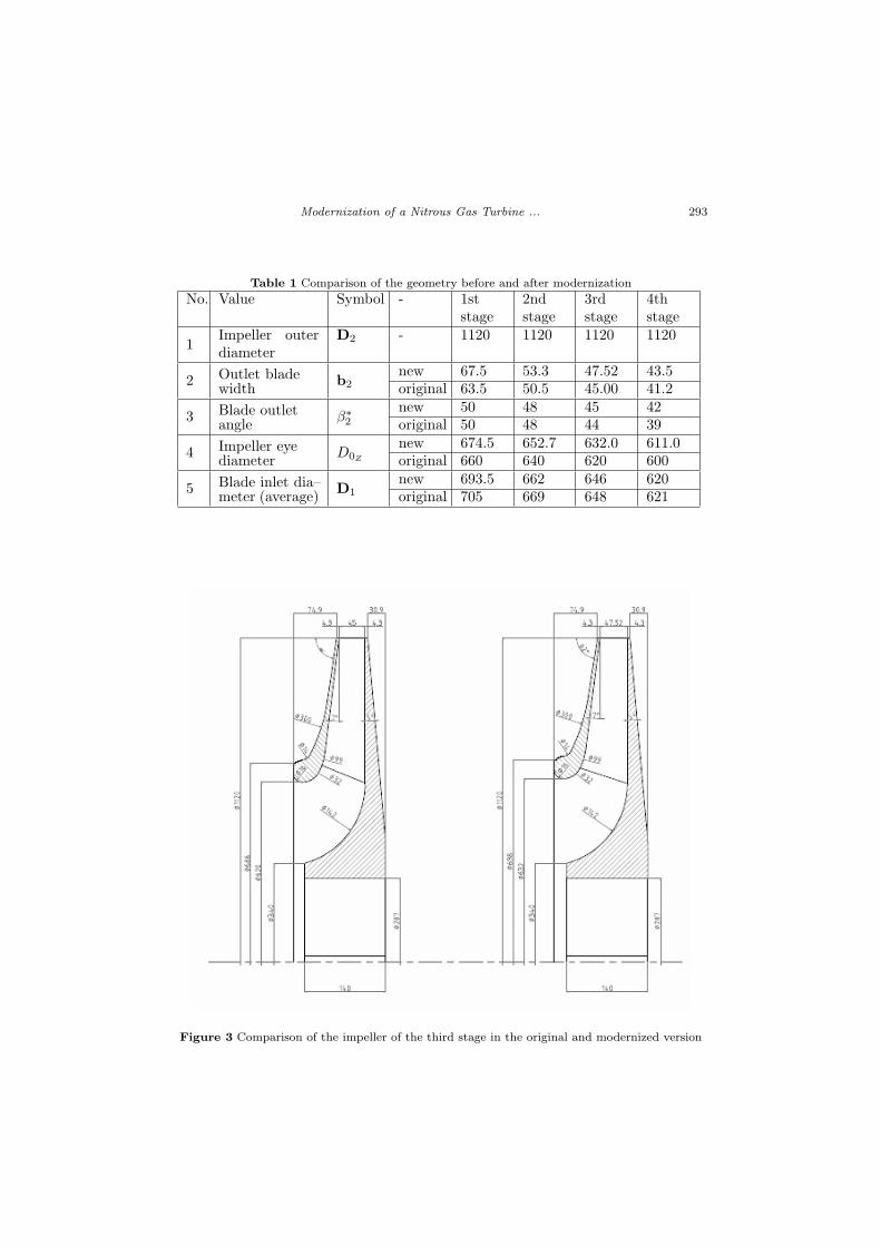
Figure 4 Design and a theoretical model of the compressor rotor
Fig. 4 shows a theoretical model of the compressor rotor used for rotor–dynamiccalculations along with the modernized rotor design realization. Tab. 2 presentsa modernized rotor equivalent rigid body properties connected to the importantchange in the impeller design of the C2102 compressor after modernization.
Table 2 Modernized rotor equivalent rigid body properties
rotor length[mm]
rotor mass[kg]
CM location[mm]
diametral inertia[kgm2]
polar inertia[kgm2]
3298 2506.8 1667 1061.0 157.82
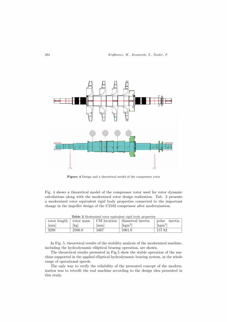
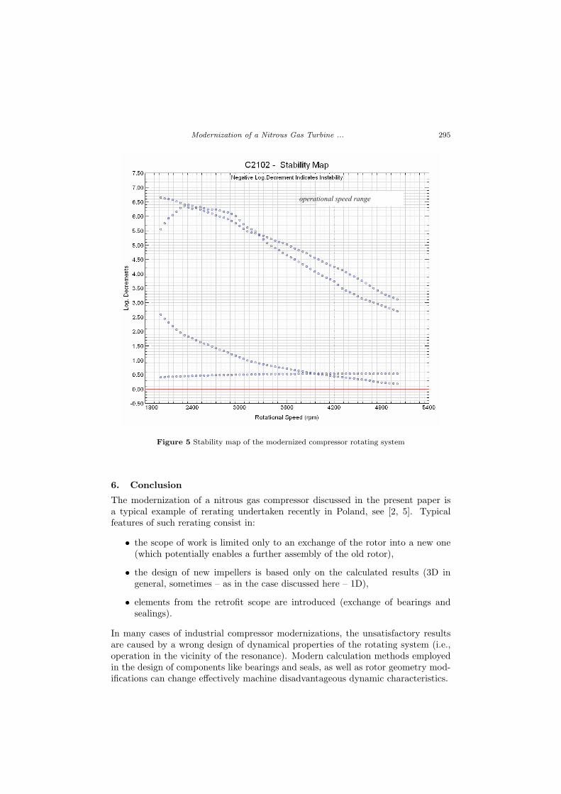
In Fig. 5, theoretical results of the stability analysis of the modernized machine,including the hydrodynamic elliptical bearing operation, are shown.
The theoretical results presented in Fig.5 show the stable operation of the ma-chine supported in the applied elliptical hydrodynamic bearing system, in the wholerange of operational speeds.
The only way to verify the reliability of the presented concept of the modern-ization was to retrofit the real machine according to the design idea presented inthis study.
Modernization of a Nitrous Gas Turbine ... 295
operational speed range
Figure 5 Stability map of the modernized compressor rotating system
6. Conclusion
The modernization of a nitrous gas compressor discussed in the present paper isa typical example of rerating undertaken recently in Poland, see [2, 5]. Typicalfeatures of such rerating consist in:
• the scope of work is limited only to an exchange of the rotor into a new one(which potentially enables a further assembly of the old rotor),
• the design of new impellers is based only on the calculated results (3D ingeneral, sometimes – as in the case discussed here – 1D),
• elements from the retrofit scope are introduced (exchange of bearings andsealings).
In many cases of industrial compressor modernizations, the unsatisfactory resultsare caused by a wrong design of dynamical properties of the rotating system (i.e.,operation in the vicinity of the resonance). Modern calculation methods employedin the design of components like bearings and seals, as well as rotor geometry mod-ifications can change effectively machine disadvantageous dynamic characteristics.
296 Kry l lowicz, W., Kozanecki, Z., Swider, P.
References
[1] Connor, O.J.: Uprating Feasibility Studies for Turbocompressors in Refinery andChemical Processes – Improving Existing Equipment, Sulzer Technical Review, 3,pp.10–13, 2007.
[2] Kozanecki, Z., Kry l lowicz, W. and Hanausek, P.: Analiza stanu technicznegoturbozespo low z linii A i B pod wzgledem sprawnosci i wydajnosci w aspekcie nowychwytycznych zawartych w opracowaniu INS Pu lawy dla potrzeb Wydzia lu Kwasu Azo-towego A–21, IMP P L, Lodz, (internal report, Institute of Turbomachinery, TUL, inPolish), 2007.
[3] Kozanecki, Z.: Badania diagnostyczne turbozespo low A i B na instalacji kwasuazotowego A–21 w celu wyjasnienia problemow z podwyzszonymi drganiami podczasich uruchomienia, IMP P L, Lodz 2007 (internal report, Institute of Turbomachinery,TUL, in Polish), 2007.
[4] Kozanecki, Z.: Rotating Systems of the Low and Medium Power Turbomachinery,Radom: ITE Publishing House, (in Polish), 2008.
[5] Kry l lowicz, W. and Kozanecki, Z.: Complex modernization of the AmmoniaCompressor, Cieplne Maszyny Przepywowe - Turbomachinery, no. 133, pp. 165–174, Lodz, 2008.
[6] Luedtke, K.H.: Process: Centrifugal Compressors. Basic Function, Operation, De-sign, Application, Springer Verlag, Berlin – Heidelberg, 2004.
[7] Meienberg, H.: The Use of Turbo–Machines in Plants for the Production of NitricAcid, Escher Wyss News, No. 3, 1958.