Embed Size (px)
Citation preview

Modern OpenGL Guide test
Alexander Overvoorde
January 2019
ContentsIntroduction 3
E-book . . . . . . . . . . . . . . . . . . . . . . . . . . . . . . . . . . . . 4Credits . . . . . . . . . . . . . . . . . . . . . . . . . . . . . . . . . . . 4Prerequisites . . . . . . . . . . . . . . . . . . . . . . . . . . . . . . . . 4
Window and OpenGL context 5Setup . . . . . . . . . . . . . . . . . . . . . . . . . . . . . . . . . . . . 6Libraries . . . . . . . . . . . . . . . . . . . . . . . . . . . . . . . . . . . 6
SFML . . . . . . . . . . . . . . . . . . . . . . . . . . . . . . . . . 7SDL . . . . . . . . . . . . . . . . . . . . . . . . . . . . . . . . . . 7GLFW . . . . . . . . . . . . . . . . . . . . . . . . . . . . . . . . . 7Others . . . . . . . . . . . . . . . . . . . . . . . . . . . . . . . . . 7
SFML . . . . . . . . . . . . . . . . . . . . . . . . . . . . . . . . . . . . 7Building . . . . . . . . . . . . . . . . . . . . . . . . . . . . . . . . 7Code . . . . . . . . . . . . . . . . . . . . . . . . . . . . . . . . . . 8
SDL . . . . . . . . . . . . . . . . . . . . . . . . . . . . . . . . . . . . . 11Building . . . . . . . . . . . . . . . . . . . . . . . . . . . . . . . . 11Code . . . . . . . . . . . . . . . . . . . . . . . . . . . . . . . . . . 11
GLFW . . . . . . . . . . . . . . . . . . . . . . . . . . . . . . . . . . . . 14Building . . . . . . . . . . . . . . . . . . . . . . . . . . . . . . . . 14Code . . . . . . . . . . . . . . . . . . . . . . . . . . . . . . . . . . 14
One more thing . . . . . . . . . . . . . . . . . . . . . . . . . . . . . . . 16
The graphics pipeline 18Vertex input . . . . . . . . . . . . . . . . . . . . . . . . . . . . . . . . 20Shaders . . . . . . . . . . . . . . . . . . . . . . . . . . . . . . . . . . . 23
Vertex shader . . . . . . . . . . . . . . . . . . . . . . . . . . . . . 23Fragment shader . . . . . . . . . . . . . . . . . . . . . . . . . . . 24Compiling shaders . . . . . . . . . . . . . . . . . . . . . . . . . . 25Combining shaders into a program . . . . . . . . . . . . . . . . . 26Making the link between vertex data and attributes . . . . . . . 27
Vertex Array Objects . . . . . . . . . . . . . . . . . . . . . . . . . . . 28
1

Drawing . . . . . . . . . . . . . . . . . . . . . . . . . . . . . . . . . . . 28Uniforms . . . . . . . . . . . . . . . . . . . . . . . . . . . . . . . . . . 30Adding some more colors . . . . . . . . . . . . . . . . . . . . . . . . . 31Element buffers . . . . . . . . . . . . . . . . . . . . . . . . . . . . . . . 32Exercises . . . . . . . . . . . . . . . . . . . . . . . . . . . . . . . . . . 35
Textures objects and parameters 35Wrapping . . . . . . . . . . . . . . . . . . . . . . . . . . . . . . . . . . 37Filtering . . . . . . . . . . . . . . . . . . . . . . . . . . . . . . . . . . . 38Loading texture images . . . . . . . . . . . . . . . . . . . . . . . . . . 40
SOIL . . . . . . . . . . . . . . . . . . . . . . . . . . . . . . . . . . 40Alternative options . . . . . . . . . . . . . . . . . . . . . . . . . . 41
Using a texture . . . . . . . . . . . . . . . . . . . . . . . . . . . . . . . 41Texture units . . . . . . . . . . . . . . . . . . . . . . . . . . . . . . . . 44Exercises . . . . . . . . . . . . . . . . . . . . . . . . . . . . . . . . . . 45
Matrices 47Basic operations . . . . . . . . . . . . . . . . . . . . . . . . . . . . . . 47
Addition and subtraction . . . . . . . . . . . . . . . . . . . . . . 47Scalar product . . . . . . . . . . . . . . . . . . . . . . . . . . . . 48
Matrix-Vector product . . . . . . . . . . . . . . . . . . . . . . . . . . . 48Translation . . . . . . . . . . . . . . . . . . . . . . . . . . . . . . 49Scaling . . . . . . . . . . . . . . . . . . . . . . . . . . . . . . . . . 49Rotation . . . . . . . . . . . . . . . . . . . . . . . . . . . . . . . . 50
Matrix-Matrix product . . . . . . . . . . . . . . . . . . . . . . . . . . . 51Combining transformations . . . . . . . . . . . . . . . . . . . . . 52
Transformations in OpenGL . . . . . . . . . . . . . . . . . . . . . . . . 52Model matrix . . . . . . . . . . . . . . . . . . . . . . . . . . . . . 53View matrix . . . . . . . . . . . . . . . . . . . . . . . . . . . . . . 53Projection matrix . . . . . . . . . . . . . . . . . . . . . . . . . . . 53Putting it all together . . . . . . . . . . . . . . . . . . . . . . . . 54
Using transformations for 3D . . . . . . . . . . . . . . . . . . . . . . . 54A simple transformation . . . . . . . . . . . . . . . . . . . . . . . 55Going 3D . . . . . . . . . . . . . . . . . . . . . . . . . . . . . . . 58
Exercises . . . . . . . . . . . . . . . . . . . . . . . . . . . . . . . . . . 60
Extra buffers 60Preparations . . . . . . . . . . . . . . . . . . . . . . . . . . . . . . . . 60Depth buffer . . . . . . . . . . . . . . . . . . . . . . . . . . . . . . . . 61Stencil buffer . . . . . . . . . . . . . . . . . . . . . . . . . . . . . . . . 62
Setting values . . . . . . . . . . . . . . . . . . . . . . . . . . . . . 63Using values in drawing operations . . . . . . . . . . . . . . . . . 64
Planar reflections . . . . . . . . . . . . . . . . . . . . . . . . . . . . . . 65Exercises . . . . . . . . . . . . . . . . . . . . . . . . . . . . . . . . . . 67
Framebuffers 67
2
Creating a new framebuffer . . . . . . . . . . . . . . . . . . . . . . . . 68Attachments . . . . . . . . . . . . . . . . . . . . . . . . . . . . . . . . 69
Texture images . . . . . . . . . . . . . . . . . . . . . . . . . . . . 69Renderbuffer Object images . . . . . . . . . . . . . . . . . . . . . 70
Using a framebuffer . . . . . . . . . . . . . . . . . . . . . . . . . . . . 70Post-processing . . . . . . . . . . . . . . . . . . . . . . . . . . . . . . . 71Changing the code . . . . . . . . . . . . . . . . . . . . . . . . . . . . . 71Post-processing effects . . . . . . . . . . . . . . . . . . . . . . . . . . . 73
Color manipulation . . . . . . . . . . . . . . . . . . . . . . . . . . 73Blur . . . . . . . . . . . . . . . . . . . . . . . . . . . . . . . . . . 75Sobel . . . . . . . . . . . . . . . . . . . . . . . . . . . . . . . . . . 76
Conclusion . . . . . . . . . . . . . . . . . . . . . . . . . . . . . . . . . 77Exercises . . . . . . . . . . . . . . . . . . . . . . . . . . . . . . . . . . 77
Geometry shaders 77Setup . . . . . . . . . . . . . . . . . . . . . . . . . . . . . . . . . . . . 78Basic geometry shader . . . . . . . . . . . . . . . . . . . . . . . . . . . 80
Input types . . . . . . . . . . . . . . . . . . . . . . . . . . . . . . 82Output types . . . . . . . . . . . . . . . . . . . . . . . . . . . . . 82Vertex input . . . . . . . . . . . . . . . . . . . . . . . . . . . . . . 83Vertex output . . . . . . . . . . . . . . . . . . . . . . . . . . . . . 83
Creating a geometry shader . . . . . . . . . . . . . . . . . . . . . . . . 84Geometry shaders and vertex attributes . . . . . . . . . . . . . . . . . 86Dynamically generating geometry . . . . . . . . . . . . . . . . . . . . . 89Conclusion . . . . . . . . . . . . . . . . . . . . . . . . . . . . . . . . . 92Exercises . . . . . . . . . . . . . . . . . . . . . . . . . . . . . . . . . . 93
Transform feedback 93Basic feedback . . . . . . . . . . . . . . . . . . . . . . . . . . . . . . . 93Feedback transform and geometry shaders . . . . . . . . . . . . . . . . 97Variable feedback . . . . . . . . . . . . . . . . . . . . . . . . . . . . . . 99Conclusion . . . . . . . . . . . . . . . . . . . . . . . . . . . . . . . . . 100Exercises . . . . . . . . . . . . . . . . . . . . . . . . . . . . . . . . . . 101
Introduction
This guide will teach you the basics of using OpenGL to develop modern graphicsapplications. There are a lot of other guides on this topic, but there are somemajor points where this guide differs from those. We will not be discussingany of the old parts of the OpenGL specification. That means you’ll be taughthow to implement things yourself, instead of using deprecated functions likeglBegin and glLight. Anything that is not directly related to OpenGL itself,like creating a window and loading textures from files, will be done using a fewsmall libraries.
3

To show you how much it pays off to do things yourself, this guide also contains alot of interactive examples to make it both fun and easy to learn all the differentaspects of using a low-level graphics library like OpenGL!
As an added bonus, you always have the opportunity to ask questions at the endof each chapter in the comments section. I’ll try to answer as many questions aspossible, but always remember that there are plenty of people out there who arewilling to help you with your issues. Make sure to help us help you by specifyingyour platform, compiler, the relevant code section, the result you expect andwhat is actually happening.
E-book
This guide is now available in e-book formats as well:
• EPUB• PDF
Credits
Thanks to all of the contributors for their help with improving the quality of thistutorial! Special thanks to the following people for their essential contributionsto the site:
• Toby Rufinus (code fixes, improved images, sample solutions for lastchapters)
• Eric Engeström (making the site mobile friendly)• Elliott Sales de Andrade (improving article text)• Aaron Hamilton (improving article text)
Prerequisites
Before we can take off, you need to make sure you have all the things you need.
• A reasonable amount of experience with C++• Graphics card compatible with OpenGL 3.2• SFML, GLFW or SDL for creating the context and handling input• GLEW to use newer OpenGL functions• SOIL for textures• GLM for vectors and matrices
Context creation will be explained for SFML, GLFW and SDL, so use whateverlibrary suites you best. See the next chapter for the differences between thethree if you’re not sure which one to use.
4

You also have the option of creating the context yourself using Win32,Xlib or Cocoa, but your code will not be portable anymore. Thatmeans you can not use the same code for all platforms.
If you’ve got everything you need, let’s begin.
Window and OpenGL context
Before you can start drawing things, you need to initialize OpenGL. This is doneby creating an OpenGL context, which is essentially a state machine that storesall data related to the rendering of your application. When your applicationcloses, the OpenGL context is destroyed and everything is cleaned up.
The problem is that creating a window and an OpenGL context is not part of theOpenGL specification. That means it is done differently on every platform outthere! Developing applications using OpenGL is all about being portable, so thisis the last thing we need. Luckily there are libraries out there that abstract thisprocess, so that you can maintain the same codebase for all supported platforms.
While the available libraries out there all have advantages and disadvantages,they do all have a certain program flow in common. You start by specifying theproperties of the game window, such as the title and the size and the propertiesof the OpenGL context, like the anti-aliasing level. Your application will theninitiate the event loop, which contains an important set of tasks that need tobe completed over and over again until the window closes. These tasks usuallyhandle window events like mouse clicks, updating the rendering state and thendrawing.
This program flow would look something like this in pseudocode:#include <libraryheaders>
int main(){
createWindow(title, width, height);createOpenGLContext(settings);
while (windowOpen){
while (event = newEvent())handleEvent(event);
updateScene();
drawGraphics();presentGraphics();
5
}
return 0;}
When rendering a frame, the results will be stored in an offscreen buffer knownas the back buffer to make sure the user only sees the final result. ThepresentGraphics() call will copy the result from the back buffer to the visiblewindow buffer, the front buffer. Every application that makes use of real-timegraphics will have a program flow that comes down to this, whether it uses alibrary or native code.
Supporting resizable windows with OpenGL introduces some complexities asresources need to be reloaded and buffers need to be recreated to fit the newwindow size. It’s more convenient for the learning process to not bother withsuch details yet, so we’ll only deal with fixed size (fullscreen) windows for now.
Setup
Instead of reading this chapter, you can make use of the OpenGLquickstart boilerplate, which makes setting up an OpenGL projectwith all of the required libraries very easy. You’ll just have to installSOIL separately.
The first thing to do when starting a new OpenGL project is to dynamically linkwith OpenGL.
• Windows: Add opengl32.lib to your linker input• Linux: Include -lGL in your compiler options• OS X: Add -framework OpenGL to your compiler options
Make sure that you do not include opengl32.dll with your application. This fileis already included with Windows and may differ per version, which will causeproblems on other computers.
The rest of the steps depend on which library you choose to use for creating thewindow and context.
Libraries
There are many libraries around that can create a window and an accompanyingOpenGL context for you. There is no best library out there, because everyone hasdifferent needs and ideals. I’ve chosen to discuss the process for the three mostpopular libraries here for completeness, but you can find more detailed guideson their respective websites. All code after this chapter will be independent ofyour choice of library here.
6

SFML
SFML is a cross-platform C++ multimedia library that provides access tographics, input, audio, networking and the system. The downside of using thislibrary is that it tries hard to be an all-in-one solution. You have little to nocontrol over the creation of the OpenGL context, as it was designed to be usedwith its own set of drawing functions.
SDL
SDL is also a cross-platform multimedia library, but targeted at C. That makesit a bit rougher to use for C++ programmers, but it’s an excellent alternativeto SFML. It supports more exotic platforms and most importantly, offers morecontrol over the creation of the OpenGL context than SFML.
GLFW
GLFW, as the name implies, is a C library specifically designed for use withOpenGL. Unlike SDL and SFML it only comes with the absolute necessities:window and context creation and input management. It offers the most controlover the OpenGL context creation out of these three libraries.
Others
There are a few other options, like freeglut and OpenGLUT, but I personallythink the aforementioned libraries are vastly superior in control, ease of use andon top of that more up-to-date.
SFML
The OpenGL context is created implicitly when opening a new window in SFML,so that’s all you have to do. SFML also comes with a graphics package, butsince we’re going to use OpenGL directly, we don’t need it.
Building
After you’ve downloaded the SFML binaries package or compiled it yourself,you’ll find the needed files in the lib and include folders.
• Add the lib folder to your library path and link with sfml-systemand sfml-window. With Visual Studio on Windows, link with thesfml-system-s and sfml-window-s files in lib/vc2008 instead.
7

• Add the include folder to your include path.
The SFML libraries have a simple naming convention for differentconfigurations. If you want to dynamically link, simply remove the -sfrom the name, define SFML_DYNAMIC and copy the shared libraries.If you want to use the binaries with debug symbols, additionallyappend -d to the name.
To verify that you’ve done this correctly, try compiling and running the followingcode:#include <SFML/System.hpp>
int main(){
sf::sleep(sf::seconds(1.f));return 0;
}
It should show a console application and exit after a second. If you run into anytrouble, you can find more detailed information for Visual Studio, Code::Blocksand gcc in the tutorials on the SFML website.
Code
Start by including the window package and defining the entry point of yourapplication.#include <SFML/Window.hpp>
int main(){
return 0;}
A window can be opened by creating a new instance of sf::Window. The basicconstructor takes an sf::VideoMode structure, a title for the window and a win-dow style. The sf::VideoMode structure specifies the width, height and option-ally the pixel depth of the window. Finally, the requirement for a fixed size win-dow is specified by overriding the default style of Style::Resize|Style::Close.It is also possible to create a fullscreen window by passing Style::Fullscreenas window style.sf::ContextSettings settings;settings.depthBits = 24;settings.stencilBits = 8;settings.antialiasingLevel = 2; // Optional// Request OpenGL version 3.2
8
settings.majorVersion = 3;settings.minorVersion = 2;settings.attributeFlags = sf::ContextSettings::Core;
sf::Window window(sf::VideoMode(800, 600), "OpenGL", sf::Style::Close, settings);
The constructor can also take an sf::ContextSettings structure that allowsyou to request an OpenGL context and specify the anti-aliasing level and theaccuracy of the depth and stencil buffers. The latter two will be discussed later,so you don’t have to worry about these yet. In the latest version of SFML, youdo need to request these manually with the code above. We request an OpenGLcontext of version 3.2 in the core profile as opposed to the compatibility modewhich is default. Using the default compatibility mode may cause problemswhile using modern OpenGL on some systems, thus we use the core profile.
Note that these settings are only a hint, SFML will try to find the closest validmatch. It will, for example, likely create a context with a newer OpenGL versionthan we specified.
When running this, you’ll notice that the application instantly closes aftercreating the window. Let’s add the event loop to deal with that.bool running = true;while (running){
sf::Event windowEvent;while (window.pollEvent(windowEvent)){
}}
When something happens to your window, an event is posted to the event queue.There is a wide variety of events, including window size changes, mouse movementand key presses. It’s up to you to decide which events require additional action,but there is at least one that needs to be handled to make your application runwell.switch (windowEvent.type){case sf::Event::Closed:
running = false;break;
}
When the user attempts to close the window, the Closed event is fired and weact on that by exiting the application. Try removing that line and you’ll see thatit’s impossible to close the window by normal means. If you prefer a fullscreen
9

window, you should add the escape key as a means to close the window:case sf::Event::KeyPressed:
if (windowEvent.key.code == sf::Keyboard::Escape)running = false;
break;
You have your window and the important events are acted upon, so you’re nowready to put something on the screen. After drawing something, you can swapthe back buffer and the front buffer with window.display().
When you run your application, you should see something like this:
Figure 1:
Note that SFML allows you to have multiple windows. If you want to makeuse of this feature, make sure to call window.setActive() to activate a certainwindow for drawing operations.
Now that you have a window and a context, there’s one more thing that needsto be done.
10
SDL
SDL comes with many different modules, but for creating a window with anaccompanying OpenGL context we’re only interested in the video module. Itwill take care of everything we need, so let’s see how to use it.
Building
After you’ve downloaded the SDL binaries or compiled them yourself, you’ll findthe needed files in the lib and include folders.
• Add the lib folder to your library path and link with SDL2 and SDL2main.• SDL uses dynamic linking, so make sure that the shared library (SDL2.dll,
SDL2.so) is with your executable.• Add the include folder to your include path.
To verify that you’re ready, try compiling and running the following snippet ofcode:#include <SDL.h>
int main(int argc, char *argv[]){
SDL_Init(SDL_INIT_EVERYTHING);
SDL_Delay(1000);
SDL_Quit();return 0;
}
It should show a console application and exit after a second. If you run into anytrouble, you can find more detailed information for all kinds of platforms andcompilers in the tutorials on the web.
Code
Start by defining the entry point of your application and include the headers forSDL.#include <SDL.h>#include <SDL_opengl.h>
int main(int argc, char *argv[]){
return 0;}
11

To use SDL in an application, you need to tell SDL which modules you needand when to unload them. You can do this with two lines of code.SDL_Init(SDL_INIT_VIDEO);...SDL_Quit();return 0;
The SDL_Init function takes a bitfield with the modules to load. The videomodule includes everything you need to create a window and an OpenGL context.
Before doing anything else, first tell SDL that you want a forward compatibleOpenGL 3.2 context:SDL_GL_SetAttribute(SDL_GL_CONTEXT_PROFILE_MASK, SDL_GL_CONTEXT_PROFILE_CORE);SDL_GL_SetAttribute(SDL_GL_CONTEXT_MAJOR_VERSION, 3);SDL_GL_SetAttribute(SDL_GL_CONTEXT_MINOR_VERSION, 2);SDL_GL_SetAttribute(SDL_GL_STENCIL_SIZE, 8);
You also need to tell SDL to create a stencil buffer, which will be relevantfor a later chapter. After that, create a window using the SDL_CreateWindowfunction.SDL_Window* window = SDL_CreateWindow("OpenGL", 100, 100, 800, 600, SDL_WINDOW_OPENGL);
The first argument specifies the title of the window, the next two are theX and Y position and the two after those are the width and height. Ifthe position doesn’t matter, you can specify SDL_WINDOWPOS_UNDEFINED orSDL_WINDOWPOS_CENTERED for the second and third argument. The final param-eter specifies window properties like:
• SDL_WINDOW_OPENGL - Create a window ready for OpenGL.• SDL_WINDOW_RESIZABLE - Create a resizable window.• Optional SDL_WINDOW_FULLSCREEN - Create a fullscreen window.
After you’ve created the window, you can create the OpenGL context:SDL_GLContext context = SDL_GL_CreateContext(window);...SDL_GL_DeleteContext(context);
The context should be destroyed right before calling SDL_Quit() to clean upthe resources.
Then comes the most important part of the program, the event loop:SDL_Event windowEvent;while (true){
if (SDL_PollEvent(&windowEvent)){
12

if (windowEvent.type == SDL_QUIT) break;}
SDL_GL_SwapWindow(window);}
The SDL_PollEvent function will check if there are any new events that have tobe handled. An event can be anything from a mouse click to the user moving thewindow. Right now, the only event you need to respond to is the user pressingthe little X button in the corner of the window. By breaking from the mainloop, SDL_Quit is called and the window and graphics surface are destroyed.SDL_GL_SwapWindow here takes care of swapping the front and back buffer afternew things have been drawn by your application.
If you have a fullscreen window, it would be preferable to use the escape key asa means to close the window.if (windowEvent.type == SDL_KEYUP &&
windowEvent.key.keysym.sym == SDLK_ESCAPE) break;
When you run your application now, you should see something like this:
Figure 2:
13
Now that you have a window and a context, there’s one more thing that needsto be done.
GLFW
GLFW is tailored specifically for using OpenGL, so it is by far the easiest to usefor our purpose.
Building
After you’ve downloaded the GLFW binaries package from the website orcompiled the library yourself, you’ll find the headers in the include folder andthe libraries for your compiler in one of the lib folders.
• Add the appropriate lib folder to your library path and link with GLFW.• Add the include folder to your include path.
You can also dynamically link with GLFW if you want to. Simply linkwith GLFWDLL and include the shared library with your executable.
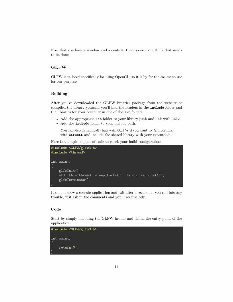
Here is a simple snippet of code to check your build configuration:#include <GLFW/glfw3.h>#include <thread>
int main(){
glfwInit();std::this_thread::sleep_for(std::chrono::seconds(1));glfwTerminate();
}
It should show a console application and exit after a second. If you run into anytrouble, just ask in the comments and you’ll receive help.
Code
Start by simply including the GLFW header and define the entry point of theapplication.#include <GLFW/glfw3.h>
int main(){
return 0;}
14

To use GLFW, it needs to be initialised when the program starts and you needto give it a chance to clean up when your program closes. The glfwInit andglfwTerminate functions are geared towards that purpose.glfwInit();...glfwTerminate();
The next thing to do is creating and configuring the window. Before callingglfwCreateWindow, we first set some options.glfwWindowHint(GLFW_CONTEXT_VERSION_MAJOR, 3);glfwWindowHint(GLFW_CONTEXT_VERSION_MINOR, 2);glfwWindowHint(GLFW_OPENGL_PROFILE, GLFW_OPENGL_CORE_PROFILE);glfwWindowHint(GLFW_OPENGL_FORWARD_COMPAT, GL_TRUE);
glfwWindowHint(GLFW_RESIZABLE, GL_FALSE);
GLFWwindow* window = glfwCreateWindow(800, 600, "OpenGL", nullptr, nullptr); // WindowedGLFWwindow* window =
glfwCreateWindow(800, 600, "OpenGL", glfwGetPrimaryMonitor(), nullptr); // Fullscreen
You’ll immediately notice the first three lines of code that are only relevantfor this library. It is specified that we require the OpenGL context to supportOpenGL 3.2 at the least. The GLFW_OPENGL_PROFILE option specifies that wewant a context that only supports the new core functionality.
The first two parameters of glfwCreateWindow specify the width andheight of the drawing surface and the third parameter specifies the windowtitle. The fourth parameter should be set to NULL for windowed mode andglfwGetPrimaryMonitor() for fullscreen mode. The last parameter allows youto specify an existing OpenGL context to share resources like textures with.The glfwWindowHint function is used to specify additional requirements for awindow.
After creating the window, the OpenGL context has to be made active:glfwMakeContextCurrent(window);
Next comes the event loop, which in the case of GLFW works a little differentlythan the other libraries. GLFW uses a so-called closed event loop, which meansyou only have to handle events when you need to. That means your event loopwill look really simple:while(!glfwWindowShouldClose(window)){
glfwSwapBuffers(window);glfwPollEvents();
}
15
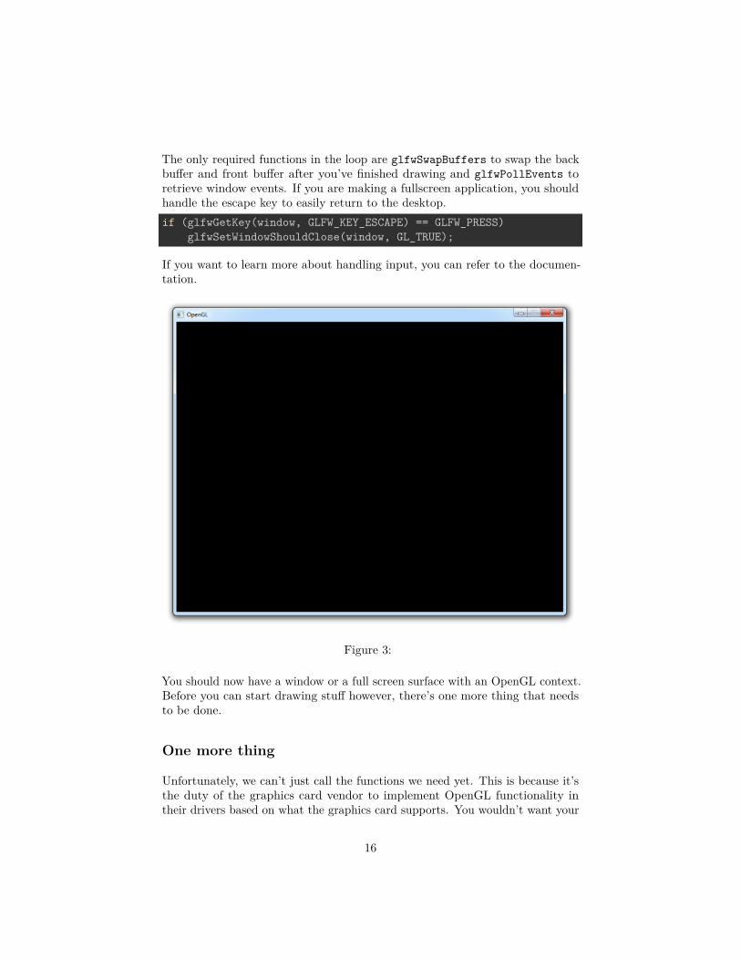
The only required functions in the loop are glfwSwapBuffers to swap the backbuffer and front buffer after you’ve finished drawing and glfwPollEvents toretrieve window events. If you are making a fullscreen application, you shouldhandle the escape key to easily return to the desktop.if (glfwGetKey(window, GLFW_KEY_ESCAPE) == GLFW_PRESS)
glfwSetWindowShouldClose(window, GL_TRUE);
If you want to learn more about handling input, you can refer to the documen-tation.
Figure 3:
You should now have a window or a full screen surface with an OpenGL context.Before you can start drawing stuff however, there’s one more thing that needsto be done.
One more thing
Unfortunately, we can’t just call the functions we need yet. This is because it’sthe duty of the graphics card vendor to implement OpenGL functionality intheir drivers based on what the graphics card supports. You wouldn’t want your
16
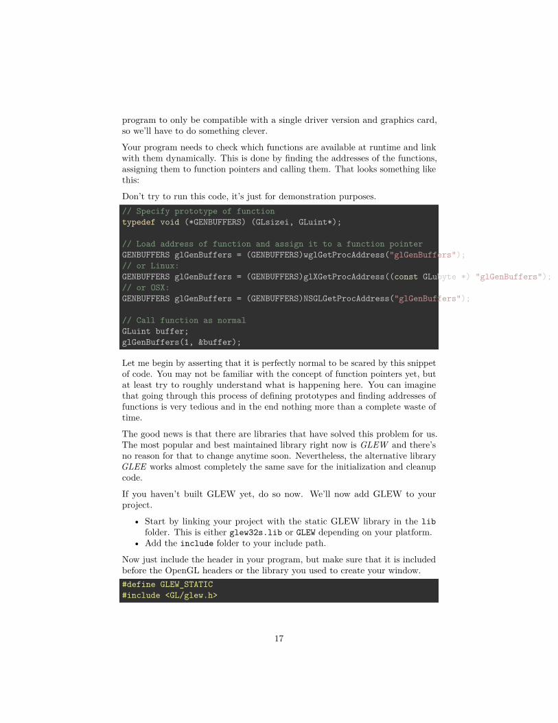
program to only be compatible with a single driver version and graphics card,so we’ll have to do something clever.
Your program needs to check which functions are available at runtime and linkwith them dynamically. This is done by finding the addresses of the functions,assigning them to function pointers and calling them. That looks something likethis:
Don’t try to run this code, it’s just for demonstration purposes.// Specify prototype of functiontypedef void (*GENBUFFERS) (GLsizei, GLuint*);
// Load address of function and assign it to a function pointerGENBUFFERS glGenBuffers = (GENBUFFERS)wglGetProcAddress("glGenBuffers");// or Linux:GENBUFFERS glGenBuffers = (GENBUFFERS)glXGetProcAddress((const GLubyte *) "glGenBuffers");// or OSX:GENBUFFERS glGenBuffers = (GENBUFFERS)NSGLGetProcAddress("glGenBuffers");
// Call function as normalGLuint buffer;glGenBuffers(1, &buffer);
Let me begin by asserting that it is perfectly normal to be scared by this snippetof code. You may not be familiar with the concept of function pointers yet, butat least try to roughly understand what is happening here. You can imaginethat going through this process of defining prototypes and finding addresses offunctions is very tedious and in the end nothing more than a complete waste oftime.
The good news is that there are libraries that have solved this problem for us.The most popular and best maintained library right now is GLEW and there’sno reason for that to change anytime soon. Nevertheless, the alternative libraryGLEE works almost completely the same save for the initialization and cleanupcode.
If you haven’t built GLEW yet, do so now. We’ll now add GLEW to yourproject.
• Start by linking your project with the static GLEW library in the libfolder. This is either glew32s.lib or GLEW depending on your platform.
• Add the include folder to your include path.
Now just include the header in your program, but make sure that it is includedbefore the OpenGL headers or the library you used to create your window.#define GLEW_STATIC#include <GL/glew.h>
17

Don’t forget to define GLEW_STATIC either using this preprocessor directive or byadding the -DGLEW_STATIC directive to your compiler command-line parametersor project settings.
If you prefer to dynamically link with GLEW, leave out the define andlink with glew32.lib instead of glew32s.lib on Windows. Don’tforget to include glew32.dll or libGLEW.so with your executable!
Now all that’s left is calling glewInit() after the creation of your window andOpenGL context. The glewExperimental line is necessary to force GLEW touse a modern OpenGL method for checking if a function is available.glewExperimental = GL_TRUE;glewInit();
Make sure that you’ve set up your project correctly by calling the glGenBuffersfunction, which was loaded by GLEW for you!GLuint vertexBuffer;glGenBuffers(1, &vertexBuffer);
printf("%u\n", vertexBuffer);
Your program should compile and run without issues and display the number 1in your console. If you need more help with using GLEW, you can refer to thewebsite or ask in the comments.
Now that we’re past all of the configuration and initialization work, I’d adviseyou to make a copy of your current project so that you won’t have to write allof the boilerplate code again when starting a new project.
Now, let’s get to drawing things!
The graphics pipeline
By learning OpenGL, you’ve decided that you want to do all of the hard workyourself. That inevitably means that you’ll be thrown in the deep, but onceyou understand the essentials, you’ll see that doing things the hard way doesn’thave to be so difficult after all. To top that all, the exercises at the end of thischapter will show you the sheer amount of control you have over the renderingprocess by doing things the modern way!
The graphics pipeline covers all of the steps that follow each other up on processingthe input data to get to the final output image. I’ll explain these steps with helpof the following illustration.
It all begins with the vertices, these are the points from which shapes liketriangles will later be constructed. Each of these points is stored with certain
18

Figure 4:
attributes and it’s up to you to decide what kind of attributes you want to store.Commonly used attributes are 3D position in the world and texture coordinates.
The vertex shader is a small program running on your graphics card that processesevery one of these input vertices individually. This is where the perspectivetransformation takes place, which projects vertices with a 3D world positiononto your 2D screen! It also passes important attributes like color and texturecoordinates further down the pipeline.
After the input vertices have been transformed, the graphics card will formtriangles, lines or points out of them. These shapes are called primitives becausethey form the basis of more complex shapes. There are some additional drawingmodes to choose from, like triangle strips and line strips. These reduce thenumber of vertices you need to pass if you want to create objects where eachnext primitive is connected to the last one, like a continuous line consisting ofseveral segments.
The following step, the geometry shader, is completely optional and was onlyrecently introduced. Unlike the vertex shader, the geometry shader can outputmore data than comes in. It takes the primitives from the shape assemblystage as input and can either pass a primitive through down to the rest of thepipeline, modify it first, completely discard it or even replace it with otherprimitive(s). Since the communication between the GPU and the rest of thePC is relatively slow, this stage can help you reduce the amount of data thatneeds to be transferred. With a voxel game for example, you could pass verticesas point vertices, along with an attribute for their world position, color andmaterial and the actual cubes can be produced in the geometry shader with apoint as input!
19
After the final list of shapes is composed and converted to screen coordinates,the rasterizer turns the visible parts of the shapes into pixel-sized fragments.The vertex attributes coming from the vertex shader or geometry shader areinterpolated and passed as input to the fragment shader for each fragment. Asyou can see in the image, the colors are smoothly interpolated over the fragmentsthat make up the triangle, even though only 3 points were specified.
The fragment shader processes each individual fragment along with its inter-polated attributes and should output the final color. This is usually done bysampling from a texture using the interpolated texture coordinate vertex at-tributes or simply outputting a color. In more advanced scenarios, there couldalso be calculations related to lighting and shadowing and special effects in thisprogram. The shader also has the ability to discard certain fragments, whichmeans that a shape will be see-through there.
Finally, the end result is composed from all these shape fragments by blendingthem together and performing depth and stencil testing. All you need to knowabout these last two right now, is that they allow you to use additional rules tothrow away certain fragments and let others pass. For example, if one triangleis obscured by another triangle, the fragment of the closer triangle should endup on the screen.
Now that you know how your graphics card turns an array of vertices into animage on the screen, let’s get to work!
Vertex input
The first thing you have to decide on is what data the graphics card is going toneed to draw your scene correctly. As mentioned above, this data comes in theform of vertex attributes. You’re free to come up with any kind of attribute youwant, but it all inevitably begins with the world position. Whether you’re doing2D graphics or 3D graphics, this is the attribute that will determine where theobjects and shapes end up on your screen in the end.
Device coordinates
When your vertices have been processed by the pipeline outlinedabove, their coordinates will have been transformed into device co-ordinates. Device X and Y coordinates are mapped to the screenbetween -1 and 1.
20

Just like a graph, the center has coordinates (0,0) and the yaxis is positive above the center. This seems unnatural becausegraphics applications usually have (0,0) in the top-left corner and(width,height) in the bottom-right corner, but it’s an excellentway to simplify 3D calculations and to stay resolution independent.
The triangle above consists of 3 vertices positioned at (0,0.5), (0.5,-0.5) and(-0.5,-0.5) in clockwise order. It is clear that the only variation between thevertices here is the position, so that’s the only attribute we need. Since we’repassing the device coordinates directly, an X and Y coordinate suffices for theposition.
OpenGL expects you to send all of your vertices in a single array, which maybe confusing at first. To understand the format of this array, let’s see what itwould look like for our triangle.
21

float vertices[] = {0.0f, 0.5f, // Vertex 1 (X, Y)0.5f, -0.5f, // Vertex 2 (X, Y)
-0.5f, -0.5f // Vertex 3 (X, Y)};
As you can see, this array should simply be a list of all vertices with theirattributes packed together. The order in which the attributes appear doesn’tmatter, as long as it’s the same for each vertex. The order of the vertices doesn’thave to be sequential (i.e. the order in which shapes are formed), but this requiresus to provide extra data in the form of an element buffer. This will be discussedat the end of this chapter as it would just complicate things for now.
The next step is to upload this vertex data to the graphics card. This is importantbecause the memory on your graphics card is much faster and you won’t haveto send the data again every time your scene needs to be rendered (about 60times per second).
This is done by creating a Vertex Buffer Object (VBO):GLuint vbo;glGenBuffers(1, &vbo); // Generate 1 buffer
The memory is managed by OpenGL, so instead of a pointer you get a positivenumber as a reference to it. GLuint is simply a cross-platform substitute forunsigned int, just like GLint is one for int. You will need this number tomake the VBO active and to destroy it when you’re done with it.
To upload the actual data to it you first have to make it the active object bycalling glBindBuffer:glBindBuffer(GL_ARRAY_BUFFER, vbo);
As hinted by the GL_ARRAY_BUFFER enum value there are other types of buffers,but they are not important right now. This statement makes the VBO we justcreated the active array buffer. Now that it’s active we can copy the vertexdata to it.glBufferData(GL_ARRAY_BUFFER, sizeof(vertices), vertices, GL_STATIC_DRAW);
Notice that this function doesn’t refer to the id of our VBO, but instead to theactive array buffer. The second parameter specifies the size in bytes. The finalparameter is very important and its value depends on the usage of the vertexdata. I’ll outline the ones related to drawing here:
• GL_STATIC_DRAW: The vertex data will be uploaded once and drawn manytimes (e.g. the world).
• GL_DYNAMIC_DRAW: The vertex data will be created once, changed fromtime to time, but drawn many times more than that.
• GL_STREAM_DRAW: The vertex data will be uploaded once and drawn once.
22

This usage value will determine in what kind of memory the data is storedon your graphics card for the highest efficiency. For example, VBOs withGL_STREAM_DRAW as type may store their data in memory that allows fasterwriting in favour of slightly slower drawing.
The vertices with their attributes have been copied to the graphics card now,but they’re not quite ready to be used yet. Remember that we can make up anykind of attribute we want and in any order, so now comes the moment whereyou have to explain to the graphics card how to handle these attributes. This iswhere you’ll see how flexible modern OpenGL really is.
Shaders
As discussed earlier, there are three shader stages your vertex data will passthrough. Each shader stage has a strictly defined purpose and in older versionsof OpenGL, you could only slightly tweak what happened and how it happened.With modern OpenGL, it’s up to us to instruct the graphics card what to dowith the data. This is why it’s possible to decide per application what attributeseach vertex should have. You’ll have to implement both the vertex and fragmentshader to get something on the screen, the geometry shader is optional and isdiscussed later.
Shaders are written in a C-style language called GLSL (OpenGL Shading Lan-guage). OpenGL will compile your program from source at runtime and copy itto the graphics card. Each version of OpenGL has its own version of the shaderlanguage with availability of a certain feature set and we will be using GLSL1.50. This version number may seem a bit off when we’re using OpenGL 3.2,but that’s because shaders were only introduced in OpenGL 2.0 as GLSL 1.10.Starting from OpenGL 3.3, this problem was solved and the GLSL version isthe same as the OpenGL version.
Vertex shader
The vertex shader is a program on the graphics card that processes each vertexand its attributes as they appear in the vertex array. Its duty is to output thefinal vertex position in device coordinates and to output any data the fragmentshader requires. That’s why the 3D transformation should take place here. Thefragment shader depends on attributes like the color and texture coordinates,which will usually be passed from input to output without any calculations.
Remember that our vertex position is already specified as device coordinatesand no other attributes exist, so the vertex shader will be fairly bare bones.#version 150 core
in vec2 position;
23

void main(){
gl_Position = vec4(position, 0.0, 1.0);}
The #version preprocessor directive is used to indicate that the code that followsis GLSL 1.50 code using OpenGL’s core profile. Next, we specify that there isonly one attribute, the position. Apart from the regular C types, GLSL hasbuilt-in vector and matrix types identified by vec* and mat* identifiers. Thetype of the values within these constructs is always a float. The number aftervec specifies the number of components (x, y, z, w) and the number after matspecifies the number of rows /columns. Since the position attribute consists ofonly an X and Y coordinate, vec2 is perfect.
You can be quite creative when working with these vertex types. Inthe example above a shortcut was used to set the first two componentsof the vec4 to those of vec2. These two lines are equal:gl_Position = vec4(position, 0.0, 1.0);gl_Position = vec4(position.x, position.y, 0.0, 1.0);
When you’re working with colors, you can also access the individualcomponents with r, g, b and a instead of x, y, z and w. This makesno difference and can help with clarity.
The final position of the vertex is assigned to the special gl_Position variable,because the position is needed for primitive assembly and many other built-inprocesses. For these to function correctly, the last value w needs to have a value of1.0f. Other than that, you’re free to do anything you want with the attributesand we’ll see how to output those when we add color to the triangle later in thischapter.
Fragment shader
The output from the vertex shader is interpolated over all the pixels on thescreen covered by a primitive. These pixels are called fragments and this iswhat the fragment shader operates on. Just like the vertex shader it has onemandatory output, the final color of a fragment. It’s up to you to write the codefor computing this color from vertex colors, texture coordinates and any otherdata coming from the vertex shader.
Our triangle only consists of white pixels, so the fragment shader simply outputsthat color every time:#version 150 core
out vec4 outColor;
24
void main(){
outColor = vec4(1.0, 1.0, 1.0, 1.0);}
You’ll immediately notice that we’re not using some built-in variable for out-putting the color, say gl_FragColor. This is because a fragment shader canin fact output multiple colors and we’ll see how to handle this when actuallyloading these shaders. The outColor variable uses the type vec4, because eachcolor consists of a red, green, blue and alpha component. Colors in OpenGL aregenerally represented as floating point numbers between 0.0 and 1.0 instead ofthe common 0 and 255.
Compiling shaders
Compiling shaders is easy once you have loaded the source code (either fromfile or as a hard-coded string). You can easily include your shader source in theC++ code through C++11 raw string literals:const char* vertexSource = R"glsl(
#version 150 core
in vec2 position;
void main(){
gl_Position = vec4(position, 0.0, 1.0);}
)glsl";
Just like vertex buffers, creating a shader itself starts with creating a shaderobject and loading data into it.GLuint vertexShader = glCreateShader(GL_VERTEX_SHADER);glShaderSource(vertexShader, 1, &vertexSource, NULL);
Unlike VBOs, you can simply pass a reference to shader functions instead ofmaking it active or anything like that. The glShaderSource function can takemultiple source strings in an array, but you’ll usually have your source code inone char array. The last parameter can contain an array of source code stringlengths, passing NULL simply makes it stop at the null terminator.
All that’s left is compiling the shader into code that can be executed by thegraphics card now:glCompileShader(vertexShader);
25

Be aware that if the shader fails to compile, e.g. because of a syntax error,glGetError will not report an error! See the block below for info on how todebug shaders.
Checking if a shader compiled successfullyGLint status;glGetShaderiv(vertexShader, GL_COMPILE_STATUS, &status);
If status is equal to GL_TRUE, then your shader was compiled suc-cessfully. Retrieving the compile logchar buffer[512];glGetShaderInfoLog(vertexShader, 512, NULL, buffer);
This will store the first 511 bytes + null terminator of the compilelog in the specified buffer. The log may also report useful warningseven when compiling was successful, so it’s useful to check it outfrom time to time when you develop your shaders.
The fragment shader is compiled in exactly the same way:GLuint fragmentShader = glCreateShader(GL_FRAGMENT_SHADER);glShaderSource(fragmentShader, 1, &fragmentSource, NULL);glCompileShader(fragmentShader);
Again, be sure to check if your shader was compiled successfully, because it willsave you from a headache later on.
Combining shaders into a program
Up until now the vertex and fragment shaders have been two separate objects.While they’ve been programmed to work together, they aren’t actually connectedyet. This connection is made by creating a program out of these two shaders.GLuint shaderProgram = glCreateProgram();glAttachShader(shaderProgram, vertexShader);glAttachShader(shaderProgram, fragmentShader);
Since a fragment shader is allowed to write to multiple buffers, you need toexplicitly specify which output is written to which buffer. This needs to happenbefore linking the program. However, since this is 0 by default and there’s onlyone output right now, the following line of code is not necessary:glBindFragDataLocation(shaderProgram, 0, "outColor");
Use glDrawBuffers when rendering to multiple buffers, because onlythe first output will be enabled by default.
26

After attaching both the fragment and vertex shaders, the connection is made bylinking the program. It is allowed to make changes to the shaders after they’vebeen added to a program (or multiple programs!), but the actual result willnot change until a program has been linked again. It is also possible to attachmultiple shaders for the same stage (e.g. fragment) if they’re parts forming thewhole shader together. A shader object can be deleted with glDeleteShader,but it will not actually be removed before it has been detached from all programswith glDetachShader.glLinkProgram(shaderProgram);
To actually start using the shaders in the program, you just have to call:glUseProgram(shaderProgram);
Just like a vertex buffer, only one program can be active at a time.
Making the link between vertex data and attributes
Although we have our vertex data and shaders now, OpenGL still doesn’t knowhow the attributes are formatted and ordered. You first need to retrieve areference to the position input in the vertex shader:GLint posAttrib = glGetAttribLocation(shaderProgram, "position");
The location is a number depending on the order of the input definitions. Thefirst and only input position in this example will always have location 0.
With the reference to the input, you can specify how the data for that input isretrieved from the array:glVertexAttribPointer(posAttrib, 2, GL_FLOAT, GL_FALSE, 0, 0);
The first parameter references the input. The second parameter specifies thenumber of values for that input, which is the same as the number of componentsof the vec. The third parameter specifies the type of each component andthe fourth parameter specifies whether the input values should be normalizedbetween -1.0 and 1.0 (or 0.0 and 1.0 depending on the format) if they aren’tfloating point numbers.
The last two parameters are arguably the most important here as they specifyhow the attribute is laid out in the vertex array. The first number specifies thestride, or how many bytes are between each position attribute in the array. Thevalue 0 means that there is no data in between. This is currently the case as theposition of each vertex is immediately followed by the position of the next vertex.The last parameter specifies the offset, or how many bytes from the start of thearray the attribute occurs. Since there are no other attributes, this is 0 as well.
It is important to know that this function will store not only the stride and the
27

offset, but also the VBO that is currently bound to GL_ARRAY_BUFFER. Thatmeans that you don’t have to explicitly bind the correct VBO when the actualdrawing functions are called. This also implies that you can use a different VBOfor each attribute.
Don’t worry if you don’t fully understand this yet, as we’ll see how to alter thisto add more attributes soon enough.glEnableVertexAttribArray(posAttrib);
Last, but not least, the vertex attribute array needs to be enabled.
Vertex Array Objects
You can imagine that real graphics programs use many different shaders andvertex layouts to take care of a wide variety of needs and special effects. Changingthe active shader program is easy enough with a call to glUseProgram, but itwould be quite inconvenient if you had to set up all of the attributes again everytime.
Luckily, OpenGL solves that problem with Vertex Array Objects (VAO). VAOsstore all of the links between the attributes and your VBOs with raw vertexdata.
A VAO is created in the same way as a VBO:GLuint vao;glGenVertexArrays(1, &vao);
To start using it, simply bind it:glBindVertexArray(vao);
As soon as you’ve bound a certain VAO, every time you call glVertexAttribPointer,that information will be stored in that VAO. This makes switching betweendifferent vertex data and vertex formats as easy as binding a different VAO! Justremember that a VAO doesn’t store any vertex data by itself, it just referencesthe VBOs you’ve created and how to retrieve the attribute values from them.
Since only calls after binding a VAO stick to it, make sure that you’ve createdand bound the VAO at the start of your program. Any vertex buffers andelement buffers bound before it will be ignored.
Drawing
Now that you’ve loaded the vertex data, created the shader programs and linkedthe data to the attributes, you’re ready to draw the triangle. The VAO that wasused to store the attribute information is already bound, so you don’t have to
28

worry about that. All that’s left is to simply call glDrawArrays in your mainloop:glDrawArrays(GL_TRIANGLES, 0, 3);
The first parameter specifies the kind of primitive (commonly point, line or trian-gle), the second parameter specifies how many vertices to skip at the beginningand the last parameter specifies the number of vertices (not primitives!) toprocess.
When you run your program now, you should see the following:
Figure 5:
If you don’t see anything, make sure that the shaders have compiled correctly,that the program has linked correctly, that the attribute array has been enabled,that the VAO has been bound before specifying the attributes, that your vertexdata is correct and that glGetError returns 0. If you can’t find the problem,try comparing your code to this sample.
29

Uniforms
Right now the white color of the triangle has been hard-coded into the shadercode, but what if you wanted to change it after compiling the shader? Asit turns out, vertex attributes are not the only way to pass data to shaderprograms. There is another way to pass data to the shaders called uniforms.These are essentially global variables, having the same value for all verticesand/or fragments. To demonstrate how to use these, let’s make it possible tochange the color of the triangle from the program itself.
By making the color in the fragment shader a uniform, it will end up lookinglike this:#version 150 core
uniform vec3 triangleColor;
out vec4 outColor;
void main(){
outColor = vec4(triangleColor, 1.0);}
The last component of the output color is transparency, which is not veryinteresting right now. If you run your program now you’ll see that the triangleis black, because the value of triangleColor hasn’t been set yet.
Changing the value of a uniform is just like setting vertex attributes, you firsthave to grab the location:GLint uniColor = glGetUniformLocation(shaderProgram, "triangleColor");
The values of uniforms are changed with any of the glUniformXY functions,where X is the number of components and Y is the type. Common types are f(float), d (double) and i (integer).glUniform3f(uniColor, 1.0f, 0.0f, 0.0f);
If you run your program now, you’ll see that the triangle is red. To make thingsa little more exciting, try varying the color with the time by doing somethinglike this in your main loop:auto t_start = std::chrono::high_resolution_clock::now();
...
auto t_now = std::chrono::high_resolution_clock::now();float time = std::chrono::duration_cast<std::chrono::duration<float>>(t_now - t_start).count();
30

glUniform3f(uniColor, (sin(time * 4.0f) + 1.0f) / 2.0f, 0.0f, 0.0f);
Although this example may not be very exciting, it does demonstrate thatuniforms are essential for controlling the behaviour of shaders at runtime. Vertexattributes on the other hand are ideal for describing a single vertex.<div class="livedemo" id="demo_c2_uniforms" style="background: url('/media/img/c2_window3.png')">
<canvas width="640" height="480"></canvas><script type="text/javascript" src="https://open.gl/content/demos/c2_uniforms.js"></script>
</div>
See the code if you have any trouble getting this to work.
Adding some more colors
Although uniforms have their place, color is something we’d rather like to specifyper corner of the triangle! Let’s add a color attribute to the vertices to accomplishthis.
We’ll first have to add the extra attributes to the vertex data. Transparencyisn’t really relevant, so we’ll only add the red, green and blue components:float vertices[] = {
0.0f, 0.5f, 1.0f, 0.0f, 0.0f, // Vertex 1: Red0.5f, -0.5f, 0.0f, 1.0f, 0.0f, // Vertex 2: Green
-0.5f, -0.5f, 0.0f, 0.0f, 1.0f // Vertex 3: Blue};
Then we have to change the vertex shader to take it as input and pass it to thefragment shader:#version 150 core
in vec2 position;in vec3 color;
out vec3 Color;
void main(){
Color = color;gl_Position = vec4(position, 0.0, 1.0);
}
And Color is added as input to the fragment shader:
31

#version 150 core
in vec3 Color;
out vec4 outColor;
void main(){
outColor = vec4(Color, 1.0);}
Make sure that the output of the vertex shader and the input of the fragmentshader have the same name, or the shaders will not be linked properly.
Now, we just need to alter the attribute pointer code a bit to accommodate forthe new X, Y, R, G, B attribute order.GLint posAttrib = glGetAttribLocation(shaderProgram, "position");glEnableVertexAttribArray(posAttrib);glVertexAttribPointer(posAttrib, 2, GL_FLOAT, GL_FALSE,
5*sizeof(float), 0);
GLint colAttrib = glGetAttribLocation(shaderProgram, "color");glEnableVertexAttribArray(colAttrib);glVertexAttribPointer(colAttrib, 3, GL_FLOAT, GL_FALSE,
5*sizeof(float), (void*)(2*sizeof(float)));
The fifth parameter is set to 5*sizeof(float) now, because each vertex consistsof 5 floating point attribute values. The offset of 2*sizeof(float) for the colorattribute is there because each vertex starts with 2 floating point values for theposition that it has to skip over.
And we’re done!
You should now have a reasonable understanding of vertex attributes and shaders.If you ran into problems, ask in the comments or have a look at the alteredsource code.
Element buffers
Right now, the vertices are specified in the order in which they are drawn. Ifyou wanted to add another triangle, you would have to add 3 additional verticesto the vertex array. There is a way to control the order, which also enables youto reuse existing vertices. This can save you a lot of memory when working withreal 3D models later on, because each point is usually occupied by a corner ofthree triangles!
32
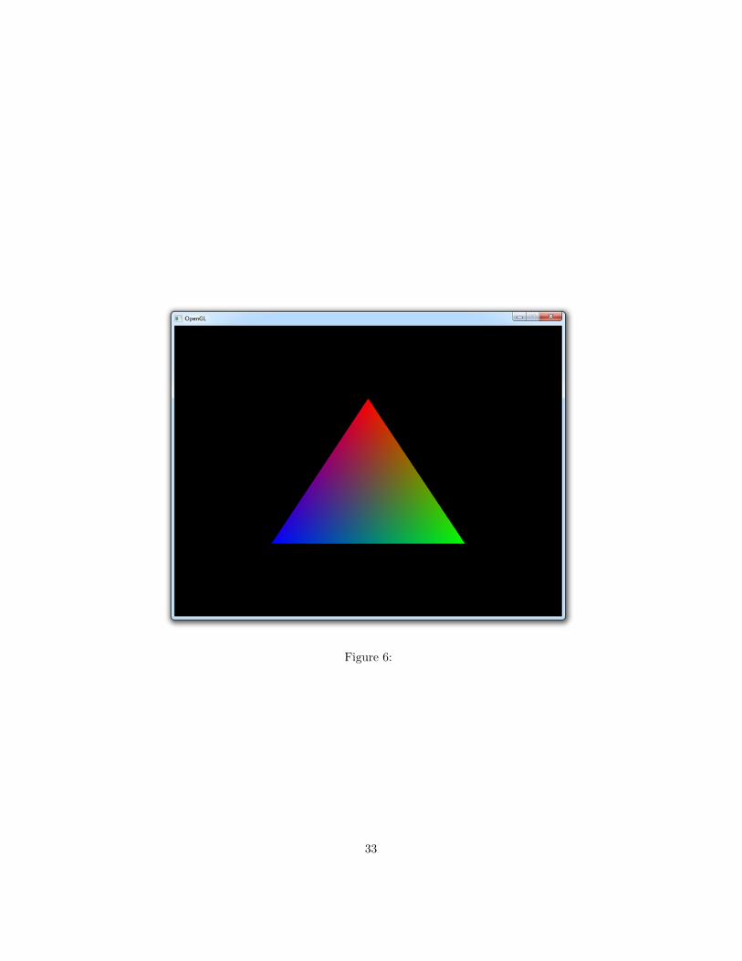
Figure 6:
33

An element array is filled with unsigned integers referring to vertices bound toGL_ARRAY_BUFFER. If we just want to draw them in the order they are in now,it’ll look like this:GLuint elements[] = {
0, 1, 2};
They are loaded into video memory through a VBO just like the vertex data:GLuint ebo;glGenBuffers(1, &ebo);
...
glBindBuffer(GL_ELEMENT_ARRAY_BUFFER, ebo);glBufferData(GL_ELEMENT_ARRAY_BUFFER,
sizeof(elements), elements, GL_STATIC_DRAW);
The only thing that differs is the target, which is GL_ELEMENT_ARRAY_BUFFERthis time.
To actually make use of this buffer, you’ll have to change the draw command:glDrawElements(GL_TRIANGLES, 3, GL_UNSIGNED_INT, 0);
The first parameter is the same as with glDrawArrays, but the other ones allrefer to the element buffer. The second parameter specifies the number of indicesto draw, the third parameter specifies the type of the element data and the lastparameter specifies the offset. The only real difference is that you’re talkingabout indices instead of vertices now.
To see how an element buffer can be beneficial, let’s try drawing a rectangleusing two triangles. We’ll start by doing it without an element buffer.float vertices[] = {
-0.5f, 0.5f, 1.0f, 0.0f, 0.0f, // Top-left0.5f, 0.5f, 0.0f, 1.0f, 0.0f, // Top-right0.5f, -0.5f, 0.0f, 0.0f, 1.0f, // Bottom-right
0.5f, -0.5f, 0.0f, 0.0f, 1.0f, // Bottom-right-0.5f, -0.5f, 1.0f, 1.0f, 1.0f, // Bottom-left-0.5f, 0.5f, 1.0f, 0.0f, 0.0f // Top-left
};
By calling glDrawArrays instead of glDrawElements like before, the elementbuffer will simply be ignored:glDrawArrays(GL_TRIANGLES, 0, 6);
34
The rectangle is rendered as it should, but the repetition of vertex data is awaste of memory. Using an element buffer allows you to reuse data:float vertices[] = {
-0.5f, 0.5f, 1.0f, 0.0f, 0.0f, // Top-left0.5f, 0.5f, 0.0f, 1.0f, 0.0f, // Top-right0.5f, -0.5f, 0.0f, 0.0f, 1.0f, // Bottom-right
-0.5f, -0.5f, 1.0f, 1.0f, 1.0f // Bottom-left};
...
GLuint elements[] = {0, 1, 2,2, 3, 0
};
...
glDrawElements(GL_TRIANGLES, 6, GL_UNSIGNED_INT, 0);
The element buffer still specifies 6 vertices to form 2 triangles like before, butnow we’re able to reuse vertices! This may not seem like much of a big dealat this point, but when your graphics application loads many models into therelatively small graphics memory, element buffers will be an important area ofoptimization.
If you run into trouble, have a look at the full source code.
This chapter has covered all of the core principles of drawing things with OpenGLand it’s absolutely essential that you have a good understanding of them beforecontinuing. Therefore I advise you to do the exercises below before diving intotextures.
Exercises
• Alter the vertex shader so that the triangle is upside down. (Solution)• Invert the colors of the triangle by altering the fragment shader. (Solution)• Change the program so that each vertex has only one color value, deter-
mining the shade of gray. (Solution)
Textures objects and parameters
Just like VBOs and VAOs, textures are objects that need to be generated firstby calling a function. It shouldn’t be a surprise at this point what this function
35

Figure 7:
36

is called.GLuint tex;glGenTextures(1, &tex);
Textures are typically used for images to decorate 3D models, but in reality theycan be used to store many different kinds of data. It’s possible to have 1D, 2Dand even 3D textures, which can be used to store bulk data on the GPU. Anexample of another use for textures is storing terrain information. This articlewill pay attention to the use of textures for images, but the principles generallyapply to all kinds of textures.glBindTexture(GL_TEXTURE_2D, tex);
Just like other objects, textures have to be bound to apply operations to them.Since images are 2D arrays of pixels, it will be bound to the GL_TEXTURE_2Dtarget.
The pixels in the texture will be addressed using texture coordinates duringdrawing operations. These coordinates range from 0.0 to 1.0 where (0,0) isconventionally the bottom-left corner and (1,1) is the top-right corner of thetexture image. The operation that uses these texture coordinates to retrievecolor information from the pixels is called sampling. There are different ways toapproach this problem, each being appropriate for different scenarios. OpenGLoffers you many options to control how this sampling is done, of which thecommon ones will be discussed here.
Wrapping
The first thing you’ll have to consider is how the texture should be sampledwhen a coordinate outside the range of 0 to 1 is given. OpenGL offers 4 ways ofhandling this:
• GL_REPEAT: The integer part of the coordinate will be ignored and arepeating pattern is formed.
• GL_MIRRORED_REPEAT: The texture will also be repeated, but it will bemirrored when the integer part of the coordinate is odd.
• GL_CLAMP_TO_EDGE: The coordinate will simply be clamped between 0 and1.
• GL_CLAMP_TO_BORDER: The coordinates that fall outside the range will begiven a specified border color.
These explanations may still be a bit cryptic and since OpenGL is all aboutgraphics, let’s see what all of these cases actually look like:
The clamping can be set per coordinate, where the equivalent of (x,y,z) intexture coordinates is called (s,t,r). Texture parameter are changed with theglTexParameter* functions as demonstrated here.
37

Figure 8:
glTexParameteri(GL_TEXTURE_2D, GL_TEXTURE_WRAP_S, GL_REPEAT);glTexParameteri(GL_TEXTURE_2D, GL_TEXTURE_WRAP_T, GL_REPEAT);
As before, the i here indicates the type of the value you want to specify. If youuse GL_CLAMP_TO_BORDER and you want to change the border color, you needto change the value of GL_TEXTURE_BORDER_COLOR by passing an RGBA floatarray:float color[] = { 1.0f, 0.0f, 0.0f, 1.0f };glTexParameterfv(GL_TEXTURE_2D, GL_TEXTURE_BORDER_COLOR, color);
This operation will set the border color to red.
Filtering
Since texture coordinates are resolution independent, they won’t always matcha pixel exactly. This happens when a texture image is stretched beyond itsoriginal size or when it’s sized down. OpenGL offers various methods to decideon the sampled color when this happens. This process is called filtering and thefollowing methods are available:
• GL_NEAREST: Returns the pixel that is closest to the coordinates.• GL_LINEAR: Returns the weighted average of the 4 pixels surrounding the
given coordinates.• GL_NEAREST_MIPMAP_NEAREST, GL_LINEAR_MIPMAP_NEAREST, GL_NEAREST_MIPMAP_LINEAR,
GL_LINEAR_MIPMAP_LINEAR: Sample from mipmaps instead.
Before discussing mipmaps, let’s first see the difference between nearest andlinear interpolation. The original image is 16 times smaller than the rectangle itwas rasterized on.
While linear interpolation gives a smoother result, it isn’t always the most idealoption. Nearest neighbour interpolation is more suited in games that want tomimic 8 bit graphics, because of the pixelated look.
You can specify which kind of interpolation should be used for two separate cases:scaling the image down and scaling the image up. These two cases are identified
38

Figure 9:
by the keywords GL_TEXTURE_MIN_FILTER and GL_TEXTURE_MAG_FILTER.glTexParameteri(GL_TEXTURE_2D, GL_TEXTURE_MIN_FILTER, GL_LINEAR);glTexParameteri(GL_TEXTURE_2D, GL_TEXTURE_MAG_FILTER, GL_LINEAR);
As you’ve seen, there is another way to filter textures: mipmaps. Mipmapsare smaller copies of your texture that have been sized down and filtered inadvance. It is recommended that you use them because they result in both ahigher quality and higher performance.glGenerateMipmap(GL_TEXTURE_2D);
Generating them is as simple as calling the function above, so there’s no excusefor not using them! Note that you do have to load the texture image itself beforemipmaps can be generated from it.
To use mipmaps, select one of the four mipmap filtering methods.
• GL_NEAREST_MIPMAP_NEAREST: Uses the mipmap that most closely matchesthe size of the pixel being textured and samples with nearest neighbourinterpolation.
• GL_LINEAR_MIPMAP_NEAREST: Samples the closest mipmap with linear in-terpolation.
• GL_NEAREST_MIPMAP_LINEAR: Uses the two mipmaps that most closelymatch the size of the pixel being textured and samples with nearestneighbour interpolation.
• GL_LINEAR_MIPMAP_LINEAR: Samples closest two mipmaps with linear in-terpolation.
There are some other texture parameters available, but they’re suited for spe-cialized operations. You can read about them in the specification.
39

Loading texture images
Now that the texture object has been configured it’s time to load the textureimage. This is done by simply loading an array of pixels into it:// Black/white checkerboardfloat pixels[] = {
0.0f, 0.0f, 0.0f, 1.0f, 1.0f, 1.0f,1.0f, 1.0f, 1.0f, 0.0f, 0.0f, 0.0f
};glTexImage2D(GL_TEXTURE_2D, 0, GL_RGB, 2, 2, 0, GL_RGB, GL_FLOAT, pixels);
The first parameter after the texture target is the level-of-detail, where 0 is thebase image. This parameter can be used to load your own mipmap images. Thesecond parameter specifies the internal pixel format, the format in which pixelsshould be stored on the graphics card. Many different formats are available,including compressed formats, so it’s certainly worth taking a look at all of theoptions. The third and fourth parameters specify the width and height of theimage. The fifth parameter should always have a value of 0 per the specification.The next two parameter describe the format of the pixels in the array that willbe loaded and the final parameter specifies the array itself. The function beginsloading the image at coordinate (0,0), so pay attention to this.
But how is the pixel array itself established? Textures in graphics applicationswill usually be a lot more sophisticated than simple patterns and will be loadedfrom files. Best practice is to have your files in a format that is natively supportedby the hardware, but it may sometimes be more convenient to load texturesfrom common image formats like JPG and PNG. Unfortunately OpenGL doesn’toffer any helper functions to load pixels from these image files, but that’s wherethird-party libraries come in handy again! The SOIL library will be discussedhere along with some of the alternatives.
SOIL
SOIL (Simple OpenGL Image Library) is a small and easy-to-use library thatloads image files directly into texture objects or creates them for you. You canstart using it in your project by linking with SOIL and adding the src directoryto your include path. It includes Visual Studio project files to compile it yourself.
Although SOIL includes functions to automatically create a texture from animage, it uses features that aren’t available in modern OpenGL. Because of thiswe’ll simply use SOIL as image loader and create the texture ourselves.int width, height;unsigned char* image =
SOIL_load_image("img.png", &width, &height, 0, SOIL_LOAD_RGB);
40

glTexImage2D(GL_TEXTURE_2D, 0, GL_RGB, width, height, 0, GL_RGB,GL_UNSIGNED_BYTE, image);
You can start configuring the texture parameters and generating mipmaps afterthis.SOIL_free_image_data(image);
You can clean up the image data right after you’ve loaded it into the texture.
As mentioned before, OpenGL expects the first pixel to be locatedin the bottom-left corner, which means that textures will be flippedwhen loaded with SOIL directly. To counteract that, the code in thetutorial will use flipped Y coordinates for texture coordinates fromnow on. That means that 0, 0 will be assumed to be the top-leftcorner instead of the bottom-left. This practice might make texturecoordinates more intuitive as a side-effect.
Alternative options
Other libraries that support a wide range of file types like SOIL are DevILand FreeImage. If you’re just interested in one file type, it’s also possible touse libraries like libpng and libjpeg directly. If you’re looking for more of anadventure, have a look at the specification of the BMP and TGA file formats,it’s not that hard to implement a loader for them yourself.
Using a texture
As you’ve seen, textures are sampled using texture coordinates and you’ll haveto add these as attributes to your vertices. Let’s modify the last sample fromthe previous chapter to include these texture coordinates. The new vertex arraywill now include the s and t coordinates for each vertex:float vertices[] = {// Position Color Texcoords
-0.5f, 0.5f, 1.0f, 0.0f, 0.0f, 0.0f, 0.0f, // Top-left0.5f, 0.5f, 0.0f, 1.0f, 0.0f, 1.0f, 0.0f, // Top-right0.5f, -0.5f, 0.0f, 0.0f, 1.0f, 1.0f, 1.0f, // Bottom-right
-0.5f, -0.5f, 1.0f, 1.0f, 1.0f, 0.0f, 1.0f // Bottom-left};
The vertex shader needs to be modified so that the texture coordinates areinterpolated over the fragments:...
in vec2 texcoord;
41

out vec3 Color;out vec2 Texcoord;
...
void main(){
Texcoord = texcoord;
Just like when the color attribute was added, the attribute pointers need to beadapted to the new format:glVertexAttribPointer(posAttrib, 2, GL_FLOAT, GL_FALSE,
7*sizeof(float), 0);glVertexAttribPointer(colAttrib, 3, GL_FLOAT, GL_FALSE,
7*sizeof(float), (void*)(2*sizeof(float)));
GLint texAttrib = glGetAttribLocation(shaderProgram, "texcoord");glEnableVertexAttribArray(texAttrib);glVertexAttribPointer(texAttrib, 2, GL_FLOAT, GL_FALSE,
7*sizeof(float), (void*)(5*sizeof(float)));
As two floats were added for the coordinates, one vertex is now 7 floats in sizeand the texture coordinate attribute consists of 2 of those floats.
Now just one thing remains: providing access to the texture in the fragmentshader to sample pixels from it. This is done by adding a uniform of typesampler2D, which will have a default value of 0. This only needs to be changedwhen access has to be provided to multiple textures, which will be considered inthe next section.
For this sample, the image of the kitten used above will be loaded using the SOILlibrary. Make sure that it is located in the working directory of the application.int width, height;unsigned char* image =
SOIL_load_image("sample.png", &width, &height, 0, SOIL_LOAD_RGB);glTexImage2D(GL_TEXTURE_2D, 0, GL_RGB, width, height, 0, GL_RGB,
GL_UNSIGNED_BYTE, image);SOIL_free_image_data(image);
To sample a pixel from a 2D texture using the sampler, the function texture canbe called with the relevant sampler and texture coordinate as parameters. We’llalso multiply the sampled color with the color attribute to get an interestingeffect. Your fragment shader will now look like this:#version 150 core
42

in vec3 Color;in vec2 Texcoord;
out vec4 outColor;
uniform sampler2D tex;
void main(){
outColor = texture(tex, Texcoord) * vec4(Color, 1.0);}
When running this application, you should get the following result:
Figure 10:
If you get a black screen, make sure that your shaders compiled successfully andthat the image is correctly loaded. If you can’t find the problem, try comparingyour code to the sample code.
43

Texture units
The sampler in your fragment shader is bound to texture unit 0. Texture unitsare references to texture objects that can be sampled in a shader. Textures arebound to texture units using the glBindTexture function you’ve used before.Because you didn’t explicitly specify which texture unit to use, the texture wasbound to GL_TEXTURE0. That’s why the default value of 0 for the sampler inyour shader worked fine.
The function glActiveTexture specifies which texture unit a texture object isbound to when glBindTexture is called.glActiveTexture(GL_TEXTURE0);
The amount of texture units supported differs per graphics card, but it will beat least 48. It is safe to say that you will never hit this limit in even the mostextreme graphics applications.
To practice with sampling from multiple textures, let’s try blending the imagesof the kitten and one of a puppy to get the best of both worlds! Let’s first modifythe fragment shader to sample from two textures and blend the pixels:...
uniform sampler2D texKitten;uniform sampler2D texPuppy;
void main(){
vec4 colKitten = texture(texKitten, Texcoord);vec4 colPuppy = texture(texPuppy, Texcoord);outColor = mix(colKitten, colPuppy, 0.5);
}
The mix function here is a special GLSL function that linearly interpolatesbetween two variables based on the third parameter. A value of 0.0 will resultin the first value, a value of 1.0 will result in the second value and a valuein between will result in a mixture of both values. You’ll have the chance toexperiment with this in the exercises.
Now that the two samplers are ready, you’ll have to assign the first two textureunits to them and bind the two textures to those units. This is done by addingthe proper glActiveTexture calls to the texture loading code.GLuint textures[2];glGenTextures(2, textures);
int width, height;unsigned char* image;
44

glActiveTexture(GL_TEXTURE0);glBindTexture(GL_TEXTURE_2D, textures[0]);image = SOIL_load_image("sample.png", &width, &height, 0, SOIL_LOAD_RGB);glTexImage2D(GL_TEXTURE_2D, 0, GL_RGB, width, height, 0, GL_RGB,
GL_UNSIGNED_BYTE, image);SOIL_free_image_data(image);glUniform1i(glGetUniformLocation(shaderProgram, "texKitten"), 0);
glTexParameteri(GL_TEXTURE_2D, GL_TEXTURE_WRAP_S, GL_CLAMP_TO_EDGE);glTexParameteri(GL_TEXTURE_2D, GL_TEXTURE_WRAP_T, GL_CLAMP_TO_EDGE);glTexParameteri(GL_TEXTURE_2D, GL_TEXTURE_MIN_FILTER, GL_LINEAR);glTexParameteri(GL_TEXTURE_2D, GL_TEXTURE_MAG_FILTER, GL_LINEAR);
glActiveTexture(GL_TEXTURE1);glBindTexture(GL_TEXTURE_2D, textures[1]);image = SOIL_load_image("sample2.png", &width, &height, 0, SOIL_LOAD_RGB);glTexImage2D(GL_TEXTURE_2D, 0, GL_RGB, width, height, 0, GL_RGB,
GL_UNSIGNED_BYTE, image);SOIL_free_image_data(image);glUniform1i(glGetUniformLocation(shaderProgram, "texPuppy"), 1);
glTexParameteri(GL_TEXTURE_2D, GL_TEXTURE_WRAP_S, GL_CLAMP_TO_EDGE);glTexParameteri(GL_TEXTURE_2D, GL_TEXTURE_WRAP_T, GL_CLAMP_TO_EDGE);glTexParameteri(GL_TEXTURE_2D, GL_TEXTURE_MIN_FILTER, GL_LINEAR);glTexParameteri(GL_TEXTURE_2D, GL_TEXTURE_MAG_FILTER, GL_LINEAR);
The texture units of the samplers are set using the glUniform function you’veseen in the previous chapter. It simply accepts an integer specifying the textureunit. Make sure that at least the wrap texture parameters are set for bothtextures. This code should result in the following image.
As always, have a look at the sample source code if you have trouble getting theprogram to work.
Now that texture sampling has been covered in this chapter, you’re finally readyto dive into transformations and ultimately 3D. The knowledge you have atthis point should be sufficient for producing most types of 2D games, exceptfor transformations like rotation and scaling which will be covered in the nextchapter.
Exercises
• Animate the blending between the textures by adding a time uniform.(Solution)
• Draw a reflection of the kitten in the lower half of the rectangle. (Solution)
45
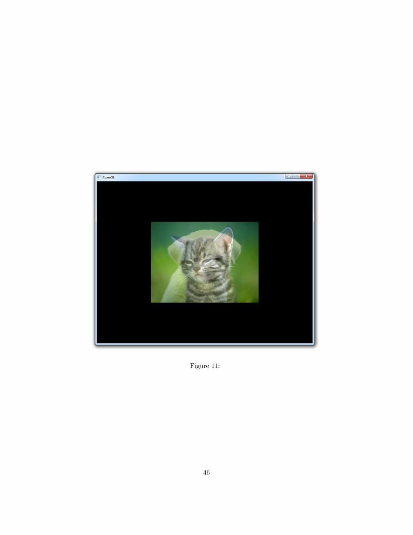
Figure 11:
46

• Now try adding distortion with sin and the time variable to simulatewater. (Expected result, Solution)
Matrices
Since this is a guide on graphics programming, this chapter will not cover a lotof the extensive theory behind matrices. Only the theory that applies to theiruse in computer graphics will be considered here and they will be explained froma programmer’s perspective. If you want to learn more about the topic, theseKhan Academy videos are a really good general introduction to the subject.
A matrix is a rectangular array of mathematical expressions, much like a two-dimensional array. Below is an example of a matrix displayed in the commonsquare brackets form.
a =
1 23 45 6
Matrices values are indexed by (i,j) where i is the row and j is the column.That is why the matrix displayed above is called a 3-by-2 matrix. To refer to aspecific value in the matrix, for example 5, the (a_{31}) notation is used.
Basic operations
To get a bit more familiar with the concept of an array of numbers, let’s firstlook at a few basic operations.
Addition and subtraction
Just like regular numbers, the addition and subtraction operators are also definedfor matrices. The only requirement is that the two operands have exactly thesame row and column dimensions.
[3 20 4
]+[4 22 2
]=[3 + 4 2 + 20 + 2 4 + 2
]=[7 42 6
][4 22 7
]−[3 20 4
]=[4 − 3 2 − 22 − 0 7 − 4
]=[1 02 3
]The values in the matrices are individually added or subtracted from each other.
47

Scalar product
The product of a scalar and a matrix is as straightforward as addition andsubtraction.
2 ·[1 23 4
]=[2 46 8
]The values in the matrices are each multiplied by the scalar.
Matrix-Vector product
The product of a matrix with another matrix is quite a bit more involved andis often misunderstood, so for simplicity’s sake I will only mention the specificcases that apply to graphics programming. To see how matrices are actuallyused to transform vectors, we’ll first dive into the product of a matrix and avector.
a b c de f g hi j k lm n o p
·
xyz1
=
a · x+ b · y + c · z + d · 1e · x+ f · y + g · z + h · 1i · x+ j · y + k · z + l · 1m · x+ n · y + o · z + p · 1
To calculate the product of a matrix and a vector, the vector is written as a4-by-1 matrix. The expressions to the right of the equals sign show how the newx, y and z values are calculated after the vector has been transformed. For thoseamong you who aren’t very math savvy, the dot is a multiplication sign.
I will mention each of the common vector transformations in this section andhow a matrix can be formed that performs them. For completeness, let’s firstconsider a transformation that does absolutely nothing.
1 0 0 00 1 0 00 0 1 00 0 0 1
·
xyz1
=
1 · x+ 0 · y + 0 · z + 0 · 10 · x+ 1 · y + 0 · z + 0 · 10 · x+ 0 · y + 1 · z + 0 · 10 · x+ 0 · y + 0 · z + 1 · 1
=
1 · x1 · y1 · z1 · 1
This matrix is called the identity matrix, because just like the number 1, it willalways return the value it was originally multiplied by.
Let’s look at the most common vector transformations now and deduce how amatrix can be formed from them.
48

Translation
To see why we’re working with 4-by-1 vectors and subsequently 4-by-4 trans-formation matrices, let’s see how a translation matrix is formed. A translationmoves a vector a certain distance in a certain direction.
Figure 12:
Can you guess from the multiplication overview what the matrix should looklike to translate a vector by (X,Y,Z)?
1 0 0 X0 1 0 Y0 0 1 Z0 0 0 1
·
xyz1
=
x+X · 1y + Y · 1z + Z · 1
1
Without the fourth column and the bottom 1 value a translation wouldn’t havebeen possible.
Scaling
A scale transformation scales each of a vector’s components by a (different)scalar. It is commonly used to shrink or stretch a vector as demonstrated below.
If you understand how the previous matrix was formed, it should not be difficultto come up with a matrix that scales a given vector by (SX,SY,SZ).
SX 0 0 00 SY 0 00 0 SZ 00 0 0 1
·
xyz1
=
SX · xSY · ySZ · z
1
If you think about it for a moment, you can see that scaling would also bepossible with a mere 3-by-3 matrix.
49

Figure 13:
Rotation
A rotation transformation rotates a vector around the origin (0,0,0) usinga given axis and angle. To understand how the axis and the angle control arotation, let’s do a small experiment.
Figure 14:
Put your thumb up against your monitor and try rotating your hand aroundit. The object, your hand, is rotating around your thumb: the rotation axis.The further you rotate your hand away from its initial position, the higher therotation angle.
In this way the rotation axis can be imagined as an arrow an object is rotatingaround. If you imagine your monitor to be a 2-dimensional XY surface, therotation axis (your thumb) is pointing in the Z direction.
Objects can be rotated around any given axis, but for now only the X, Y and Zaxis are important. You’ll see later in this chapter that any rotation axis can beestablished by rotating around the X, Y and Z axis simultaneously.
The matrices for rotating around the three axes are specified here. The rotationangle is indicated by the theta (θ).
50
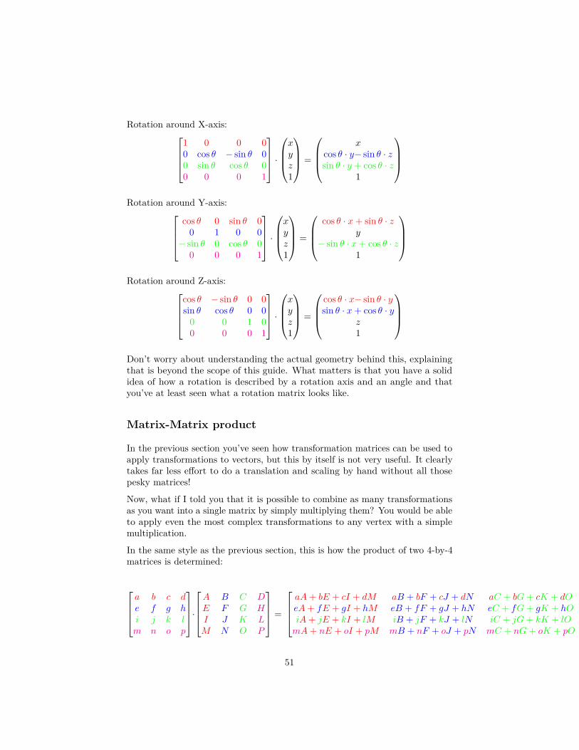
Rotation around X-axis:1 0 0 00 cos θ − sin θ 00 sin θ cos θ 00 0 0 1
·
xyz1
=
x
cos θ · y− sin θ · zsin θ · y + cos θ · z
1
Rotation around Y-axis:
cos θ 0 sin θ 00 1 0 0
− sin θ 0 cos θ 00 0 0 1
·
xyz1
=
cos θ · x+ sin θ · z
y− sin θ · x+ cos θ · z
1
Rotation around Z-axis:
cos θ − sin θ 0 0sin θ cos θ 0 0
0 0 1 00 0 0 1
·
xyz1
=
cos θ · x− sin θ · ysin θ · x+ cos θ · y
z1
Don’t worry about understanding the actual geometry behind this, explainingthat is beyond the scope of this guide. What matters is that you have a solididea of how a rotation is described by a rotation axis and an angle and thatyou’ve at least seen what a rotation matrix looks like.
Matrix-Matrix product
In the previous section you’ve seen how transformation matrices can be used toapply transformations to vectors, but this by itself is not very useful. It clearlytakes far less effort to do a translation and scaling by hand without all thosepesky matrices!
Now, what if I told you that it is possible to combine as many transformationsas you want into a single matrix by simply multiplying them? You would be ableto apply even the most complex transformations to any vertex with a simplemultiplication.
In the same style as the previous section, this is how the product of two 4-by-4matrices is determined:
a b c de f g hi j k lm n o p
·
A B C DE F G HI J K LM N O P
=
aA+ bE + cI + dM aB + bF + cJ + dN aC + bG+ cK + dO aD + bH + cL+ dPeA+ fE + gI + hM eB + fF + gJ + hN eC + fG+ gK + hO eD + fH + gL+ hPiA+ jE + kI + lM iB + jF + kJ + lN iC + jG+ kK + lO iD + jH + kL+ lPmA+ nE + oI + pM mB + nF + oJ + pN mC + nG+ oK + pO mD + nH + oL+ pP
51

The above is commonly recognized among mathematicians as an indecipherablemess. To get a better idea of what’s going on, let’s consider two 2-by-2 matricesinstead.
[1 23 4
]·[a bc d
]=[1 · a+ 2 · c 1 · b+ 2 · d3 · a+ 4 · c 3 · b+ 4 · d
]Try to see the pattern here with help of the colors. The factors on the left side(1,2 and 3,4) of the multiplication dot are the values in the row of the firstmatrix. The factors on the right side are the values in the rows of the secondmatrix repeatedly. It is not necessary to remember how exactly this works, butit’s good to have seen how it’s done at least once.
Combining transformations
To demonstrate the multiplication of two matrices, let’s try scaling a given vectorby (2,2,2) and translating it by (1,2,3). Given the translation and scalingmatrices above, the following product is calculated:
Mtranslate ·Mscale =
1 0 0 10 1 0 20 0 1 30 0 0 1
·
2 0 0 00 2 0 00 0 2 00 0 0 1
=
2 0 0 10 2 0 20 0 2 30 0 0 1
Notice how we want to scale the vector first, but the scale transformation comeslast in the multiplication. Pay attention to this when combining transformationsor you’ll get the opposite of what you’ve asked for.
Now, let’s try to transform a vector and see if it worked:
2 0 0 10 2 0 20 0 2 30 0 0 1
·
xyz1
=
2x+ 12y + 22z + 3
1
Perfect! The vector is first scaled by two and then shifted in position by (1,2,3).
Transformations in OpenGL
You’ve seen in the previous sections how basic transformations can be appliedto vectors to move them around in the world. The job of transforming 3Dpoints into 2D coordinates on your screen is also accomplished through matrixtransformations. Just like the graphics pipeline, transforming a vector is done
52

Figure 15:
step-by-step. Although OpenGL allows you to decide on these steps yourself, all3D graphics applications use a variation of the process described here.
Each transformation transforms a vector into a new coordinate system, thusmoving to the next step. These transformations and coordinate systems will bediscussed below in more detail.
Model matrix
The model matrix transforms a position in a model to the position in the world.This position is affected by the position, scale and rotation of the model that isbeing drawn. It is generally a combination of the simple transformations you’veseen before. If you are already specifying your vertices in world coordinates(common when drawing a simple test scene), then this matrix can simply be setto the identity matrix.
View matrix
In real life you’re used to moving the camera to alter the view of a certain scene,in OpenGL it’s the other way around. The camera in OpenGL cannot move andis defined to be located at (0,0,0) facing the negative Z direction. That meansthat instead of moving and rotating the camera, the world is moved and rotatedaround the camera to construct the appropriate view.
Older versions of OpenGL forced you to useModelView and Projectiontransformations. The ModelView matrix combined the model andview transformations into one. I personally find it is easier to separatethe two, so the view transformation can be modified independentlyof the model matrix.
That means that to simulate a camera transformation, you actually have totransform the world with the inverse of that transformation. Example: if youwant to move the camera up, you have to move the world down instead.
Projection matrix
After the world has been aligned with your camera using the view transformation,the projection transformation can be applied, resulting in the clip coordinates.
53

If you’re doing a perspective transformation, these clip coordinates are not readyto be used as normalized device coordinates just yet.
To transform the clipping coordinate into a normalized device coordinate, per-spective division has to be performed. A clipping coordinate resulting from aperspective projection has a number different than 1 in the fourth row, alsoknown as w. This number directly reflects the effect of objects further awaybeing smaller than those up front.
vnormalized =
xclip/wclipyclip/wclipzclip/wclip
The x and y coordinates will be in the familiar -1 and 1 range now, whichOpenGL can transform into window coordinates. The z is known as the depthand will play an important role in the next chapter.
The coordinates resulting from the projection transformation are called clippingcoordinates because the value of w is used to determine whether an object is tooclose or behind the camera or too far away to be drawn. The projection matrixis created with those limits, so you’ll be able to specify these yourself.
Putting it all together
To sum it all up, the final transformation of a vertex is the product of the model,view and projection matrices.
v′ = Mproj ·Mview ·Mmodel · v
This operation is typically performed in the vertex shader and assigned to thegl_Position return value in clipping coordinates. OpenGL will perform theperspective division and transformation into window coordinates. It is importantto be aware of these steps, because you’ll have to do them yourself when workingwith techniques like shadow mapping.
Using transformations for 3D
Now that you know three important transformations, it is time to implementthese in code to create an actual 3D scene. You can use any of the programsdeveloped in the last two chapters as a base, but I’ll use the texture blendingsample from the end of the last chapter here.
To introduce matrices in the code, we can make use of the GLM (OpenGL Math)library. This library comes with vector and matrix classes and will handle all
54

the math efficiently without ever having to worry about it. It is a header-onlylibrary, which means you don’t have to link with anything.
To use it, add the GLM root directory to your include path and include thesethree headers:#include <glm/glm.hpp>#include <glm/gtc/matrix_transform.hpp>#include <glm/gtc/type_ptr.hpp>
The second header includes functions to ease the calculation of the view andprojection matrices. The third header adds functionality for converting a matrixobject into a float array for usage in OpenGL.
A simple transformation
Before diving straight into 3D, let’s first try a simple 2D rotation.glm::mat4 trans = glm::mat4(1.0f);trans = glm::rotate(trans, glm::radians(180.0f), glm::vec3(0.0f, 0.0f, 1.0f));
The first line creates a new 4-by-4 matrix and initializes it to the identity matrix.The glm::rotate function multiplies this matrix by a rotation transformationof 180 degrees around the Z axis. Remember that since the screen lies in theXY plane, the Z axis is the axis you want to rotate points around.
To see if it works, let’s try to rotate a vector with this transformation:glm::vec4 result = trans * glm::vec4(1.0f, 0.0f, 0.0f, 1.0f);printf("%f, %f, %f\n", result.x, result.y, result.z);
As expected, the output is (-1,0,0). A counter-clockwise rotation of 180 degreesof a vector pointing to the right results in a vector pointing to the left. Notethat the rotation would be clockwise if an axis (0,0,-1) was used.
The next step is to perform this transformation in the vertex shader to rotateevery drawn vertex. GLSL has a special mat4 type to hold matrices and we canuse that to upload the transformation to the GPU as uniform.GLint uniTrans = glGetUniformLocation(shaderProgram, "trans");glUniformMatrix4fv(uniTrans, 1, GL_FALSE, glm::value_ptr(trans));
The second parameter of the glUniformMatrix4fv function specifies how manymatrices are to be uploaded, because you can have arrays of matrices in GLSL.The third parameter specifies whether the specified matrix should be transposedbefore usage. This is related to the way matrices are stored as float arrays inmemory; you don’t have to worry about it. The last parameter specifies thematrix to upload, where the glm::value_ptr function converts the matrix classinto an array of 16 (4x4) floats.
55
All that remains is updating the vertex shader to include this uniform and use itto transform each vertex:#version 150 core
in vec2 position;in vec3 color;in vec2 texcoord;
out vec3 Color;out vec2 Texcoord;
uniform mat4 trans;
void main(){
Color = color;Texcoord = texcoord;gl_Position = trans * vec4(position, 0.0, 1.0);
}
The primitives in your scene will now be upside down.
To spice things up a bit, you could change the rotation with time:auto t_start = std::chrono::high_resolution_clock::now();
...
// Calculate transformationauto t_now = std::chrono::high_resolution_clock::now();float time = std::chrono::duration_cast<std::chrono::duration<float>>(t_now - t_start).count();
glm::mat4 trans;trans = glm::rotate(
trans,time * glm::radians(180.0f),glm::vec3(0.0f, 0.0f, 1.0f)
);glUniformMatrix4fv(uniTrans, 1, GL_FALSE, glm::value_ptr(trans));
// Draw a rectangle from the 2 triangles using 6 indicesglDrawElements(GL_TRIANGLES, 6, GL_UNSIGNED_INT, 0);
...
This will result in something like this:
56

Figure 16:
57

<div class="livedemo" id="demo_c4_rotation" style="background: url('/media/img/c4_window2.png')"><canvas width="640" height="480"></canvas><script type="text/javascript" src="https://open.gl/content/demos/c4_rotation.js"></script>
</div>
You can find the full code here if you have any issues.
Going 3D
The rotation above can be considered the model transformation, because ittransforms the vertices in object space to world space using the rotation of theobject.glm::mat4 view = glm::lookAt(
glm::vec3(1.2f, 1.2f, 1.2f),glm::vec3(0.0f, 0.0f, 0.0f),glm::vec3(0.0f, 0.0f, 1.0f)
);GLint uniView = glGetUniformLocation(shaderProgram, "view");glUniformMatrix4fv(uniView, 1, GL_FALSE, glm::value_ptr(view));
To create the view transformation, GLM offers the useful glm::lookAt functionthat simulates a moving camera. The first parameter specifies the position ofthe camera, the second the point to be centered on-screen and the third the upaxis. Here up is defined as the Z axis, which implies that the XY plane is the“ground”.glm::mat4 proj = glm::perspective(glm::radians(45.0f), 800.0f / 600.0f, 1.0f, 10.0f);GLint uniProj = glGetUniformLocation(shaderProgram, "proj");glUniformMatrix4fv(uniProj, 1, GL_FALSE, glm::value_ptr(proj));
Similarly, GLM comes with the glm::perspective function to create a per-spective projection matrix. The first parameter is the vertical field-of-view, thesecond parameter the aspect ratio of the screen and the last two parameters arethe near and far planes.
Field-of-view The field-of-view defines the angle between the topand bottom of the 2D surface on which the world will be projected.Zooming in games is often accomplished by decreasing this angleas opposed to moving the camera closer, because it more closelyresembles real life.
By decreasing the angle, you can imagine that the “rays” from thecamera spread out less and thus cover a smaller area of the scene.
The near and far planes are known as the clipping planes. Any vertex closer tothe camera than the near clipping plane and any vertex farther away than thefar clipping plane is clipped as these influence the w value.
58

Figure 17:
Now piecing it all together, the vertex shader looks something like this:#version 150 core
in vec2 position;in vec3 color;in vec2 texcoord;
out vec3 Color;out vec2 Texcoord;
uniform mat4 model;uniform mat4 view;uniform mat4 proj;
void main(){
Color = color;Texcoord = texcoord;gl_Position = proj * view * model * vec4(position, 0.0, 1.0);
}
Notice that I’ve renamed the matrix previously known as trans to model and itis still updated every frame.<div class="livedemo" id="demo_c4_3d" style="background: url('/media/img/c4_window3.png')">
<canvas width="640" height="480"></canvas><script type="text/javascript" src="https://open.gl/content/demos/c4_3d.js"></script>
</div>
Success! You can find the full code here if you get stuck.
59

Exercises
• Make the rectangle with the blended image grow bigger and smaller withsin. (Solution)
• Make the rectangle flip around the X axis after pressing the space bar andslowly stop again. (Solution)
Extra buffers
Up until now there is only one type of output buffer you’ve made use of, the colorbuffer. This chapter will discuss two additional types, the depth buffer and thestencil buffer. For each of these a problem will be presented and subsequentlysolved with that specific buffer.
Preparations
To best demonstrate the use of these buffers, let’s draw a cube instead of a flatshape. The vertex shader needs to be modified to accept a third coordinate:in vec3 position;...gl_Position = proj * view * model * vec4(position, 1.0);
We’re also going to need to alter the color again later in this chapter, so makesure the fragment shader multiplies the texture color by the color attribute:vec4 texColor = mix(texture(texKitten, Texcoord),
texture(texPuppy, Texcoord), 0.5);outColor = vec4(Color, 1.0) * texColor;
Vertices are now 8 floats in size, so you’ll have to update the vertex attributeoffsets and strides as well. Finally, add the extra coordinate to the vertex array:float vertices[] = {
// X Y Z R G B U V-0.5f, 0.5f, 0.0f, 1.0f, 0.0f, 0.0f, 0.0f, 0.0f,0.5f, 0.5f, 0.0f, 0.0f, 1.0f, 0.0f, 1.0f, 0.0f,0.5f, -0.5f, 0.0f, 0.0f, 0.0f, 1.0f, 1.0f, 1.0f,
-0.5f, -0.5f, 0.0f, 1.0f, 1.0f, 1.0f, 0.0f, 1.0f};
Confirm that you’ve made all the required changes by running your programand checking if it still draws a flat spinning image of a kitten blended with apuppy. A single cube consists of 36 vertices (6 sides * 2 triangles * 3 vertices),so I will ease your life by providing the array here.
60
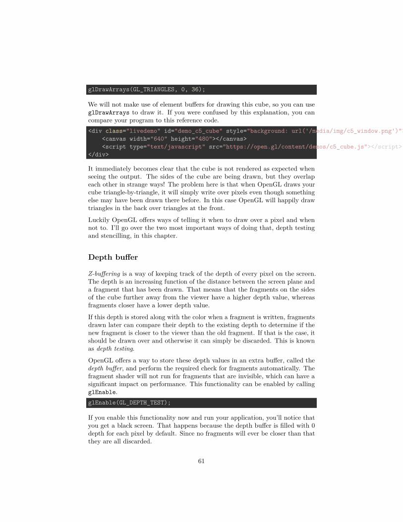
glDrawArrays(GL_TRIANGLES, 0, 36);
We will not make use of element buffers for drawing this cube, so you can useglDrawArrays to draw it. If you were confused by this explanation, you cancompare your program to this reference code.<div class="livedemo" id="demo_c5_cube" style="background: url('/media/img/c5_window.png')">
<canvas width="640" height="480"></canvas><script type="text/javascript" src="https://open.gl/content/demos/c5_cube.js"></script>
</div>
It immediately becomes clear that the cube is not rendered as expected whenseeing the output. The sides of the cube are being drawn, but they overlapeach other in strange ways! The problem here is that when OpenGL draws yourcube triangle-by-triangle, it will simply write over pixels even though somethingelse may have been drawn there before. In this case OpenGL will happily drawtriangles in the back over triangles at the front.
Luckily OpenGL offers ways of telling it when to draw over a pixel and whennot to. I’ll go over the two most important ways of doing that, depth testingand stencilling, in this chapter.
Depth buffer
Z-buffering is a way of keeping track of the depth of every pixel on the screen.The depth is an increasing function of the distance between the screen plane anda fragment that has been drawn. That means that the fragments on the sidesof the cube further away from the viewer have a higher depth value, whereasfragments closer have a lower depth value.
If this depth is stored along with the color when a fragment is written, fragmentsdrawn later can compare their depth to the existing depth to determine if thenew fragment is closer to the viewer than the old fragment. If that is the case, itshould be drawn over and otherwise it can simply be discarded. This is knownas depth testing.
OpenGL offers a way to store these depth values in an extra buffer, called thedepth buffer, and perform the required check for fragments automatically. Thefragment shader will not run for fragments that are invisible, which can have asignificant impact on performance. This functionality can be enabled by callingglEnable.glEnable(GL_DEPTH_TEST);
If you enable this functionality now and run your application, you’ll notice thatyou get a black screen. That happens because the depth buffer is filled with 0depth for each pixel by default. Since no fragments will ever be closer than thatthey are all discarded.
61

The depth buffer can be cleared along with the color buffer by extending theglClear call:glClear(GL_COLOR_BUFFER_BIT | GL_DEPTH_BUFFER_BIT);
The default clear value for the depth is 1.0f, which is equal to the depth ofyour far clipping plane and thus the furthest depth that can be represented. Allfragments will be closer than that, so they will no longer be discarded.<div class="livedemo" id="demo_c5_depth" style="background: url('/media/img/c5_window2.png')">
<canvas width="640" height="480"></canvas><script type="text/javascript" src="https://open.gl/content/demos/c5_depth.js"></script>
</div>
With the depth test capability enabled, the cube is now rendered correctly. Justlike the color buffer, the depth buffer has a certain amount of bits of precisionwhich can be specified by you. Less bits of precision reduce the extra memoryuse, but can introduce rendering errors in more complex scenes.
Stencil buffer
The stencil buffer is an optional extension of the depth buffer that gives youmore control over the question of which fragments should be drawn and whichshouldn’t. Like the depth buffer, a value is stored for every pixel, but thistime you get to control when and how this value changes and when a fragmentshould be drawn depending on this value. Note that if the depth test fails, thestencil test no longer determines whether a fragment is drawn or not, but thesefragments can still affect values in the stencil buffer!
To get a bit more acquainted with the stencil buffer before using it, let’s startby analyzing a simple example.
Figure 18:
In this case the stencil buffer was first cleared with zeroes and then a rectangleof ones was drawn to it. The drawing operation of the cube uses the values fromthe stencil buffer to only draw fragments with a stencil value of 1.
62

Now that you have an understanding of what the stencil buffer does, we’ll lookat the relevant OpenGL calls.glEnable(GL_STENCIL_TEST);
Stencil testing is enabled with a call to glEnable, just like depth testing. Youdon’t have to add this call to your code just yet. I’ll first go over the API detailsin the next two sections and then we’ll make a cool demo.
Setting values
Regular drawing operations are used to determine which values in the stencilbuffer are affected by any stencil operation. If you want to affect a rectangleof values like in the sample above, simply draw a 2D quad in that area. Whathappens to those values can be controlled by you using the glStencilFunc,glStencilOp and glStencilMask functions.
The glStencilFunc call is used to specify the conditions under which a fragmentpasses the stencil test. Its parameters are discussed below.
• func: The test function, can be GL_NEVER, GL_LESS, GL_LEQUAL,GL_GREATER, GL_GEQUAL, GL_EQUAL, GL_NOTEQUAL, and GL_ALWAYS.
• ref: A value to compare the stencil value to using the test function.• mask: A bitwise AND operation is performed on the stencil value and
reference value with this mask value before comparing them.
If you don’t want stencils with a value lower than 2 to be affected, you woulduse:glStencilFunc(GL_GEQUAL, 2, 0xFF);
The mask value is set to all ones (in case of an 8 bit stencil buffer), so it will notaffect the test.
The glStencilOp call specifies what should happen to stencil values dependingon the outcome of the stencil and depth tests. The parameters are:
• sfail: Action to take if the stencil test fails.• dpfail: Action to take if the stencil test is successful, but the depth test
failed.• dppass: Action to take if both the stencil test and depth tests pass.
Stencil values can be modified in the following ways:
• GL_KEEP: The current value is kept.• GL_ZERO: The stencil value is set to 0.• GL_REPLACE: The stencil value is set to the reference value in the
glStencilFunc call.• GL_INCR: The stencil value is increased by 1 if it is lower than the maximum
value.
63

• GL_INCR_WRAP: Same as GL_INCR, with the exception that the value is setto 0 if the maximum value is exceeded.
• GL_DECR: The stencil value is decreased by 1 if it is higher than 0.• GL_DECR_WRAP: Same as GL_DECR, with the exception that the value is set
to the maximum value if the current value is 0 (the stencil buffer storesunsigned integers).
• GL_INVERT: A bitwise invert is applied to the value.
Finally, glStencilMask can be used to control the bits that are written to thestencil buffer when an operation is run. The default value is all ones, whichmeans that the outcome of any operation is unaffected.
If, like in the example, you want to set all stencil values in a rectangular area to1, you would use the following calls:glStencilFunc(GL_ALWAYS, 1, 0xFF);glStencilOp(GL_KEEP, GL_KEEP, GL_REPLACE);glStencilMask(0xFF);
In this case the rectangle shouldn’t actually be drawn to the color buffer, sinceit is only used to determine which stencil values should be affected.glColorMask(GL_FALSE, GL_FALSE, GL_FALSE, GL_FALSE);glDepthMask(GL_FALSE);
The glColorMask function allows you to specify which data is written to thecolor buffer during a drawing operation. In this case you would want to disableall color channels (red, green, blue, alpha). Writing to the depth buffer needs tobe disabled separately as well with glDepthMask, so that cube drawing operationwon’t be affected by leftover depth values of the rectangle. This is cleaner thansimply clearing the depth buffer again later.
Using values in drawing operations
With the knowledge about setting values, using them for testing fragments indrawing operations becomes very simple. All you need to do now is re-enablecolor and depth writing if you had disabled those earlier and setting the testfunction to determine which fragments are drawn based on the values in thestencil buffer.glStencilFunc(GL_EQUAL, 1, 0xFF);
If you use this call to set the test function, the stencil test will only pass forpixels with a stencil value equal to 1. A fragment will only be drawn if it passesboth the stencil and depth test, so setting the glStencilOp is not necessary. Inthe case of the example above only the stencil values in the rectangular areawere set to 1, so only the cube fragments in that area will be drawn.
64
glStencilMask(0x00);
One small detail that is easy to overlook is that the cube draw call could stillaffect values in the stencil buffer. This problem can be solved by setting thestencil bit mask to all zeroes, which effectively disables stencil writing.
Planar reflections
Let’s spice up the demo we have right now a bit by adding a floor with a reflectionunder the cube. I’ll add the vertices for the floor to the same vertex buffer thecube is currently using to keep things simple:float vertices[] = {
...
-1.0f, -1.0f, -0.5f, 0.0f, 0.0f, 0.0f, 0.0f, 0.0f,1.0f, -1.0f, -0.5f, 0.0f, 0.0f, 0.0f, 1.0f, 0.0f,1.0f, 1.0f, -0.5f, 0.0f, 0.0f, 0.0f, 1.0f, 1.0f,1.0f, 1.0f, -0.5f, 0.0f, 0.0f, 0.0f, 1.0f, 1.0f,
-1.0f, 1.0f, -0.5f, 0.0f, 0.0f, 0.0f, 0.0f, 1.0f,-1.0f, -1.0f, -0.5f, 0.0f, 0.0f, 0.0f, 0.0f, 0.0f
}
Now add the extra draw call to your main loop:glDrawArrays(GL_TRIANGLES, 36, 6);
To create the reflection of the cube itself, it is sufficient to draw it again butinverted on the Z-axis:model = glm::scale(
glm::translate(model, glm::vec3(0, 0, -1)),glm::vec3(1, 1, -1)
);glUniformMatrix4fv(uniModel, 1, GL_FALSE, glm::value_ptr(model));glDrawArrays(GL_TRIANGLES, 0, 36);
I’ve set the color of the floor vertices to black so that the floor does not displaythe texture image, so you’ll want to change the clear color to white to be able tosee it. I’ve also changed the camera parameters a bit to get a good view of thescene.<div class="livedemo" id="demo_c5_floor" style="background: url('/media/img/c5_window3.png')">
<canvas width="640" height="480"></canvas><script type="text/javascript" src="https://open.gl/content/demos/c5_floor.js"></script>
</div>
Two issues are noticeable in the rendered image:
65
• The floor occludes the reflection because of depth testing.• The reflection is visible outside of the floor.
The first problem is easy to solve by temporarily disabling writing to the depthbuffer when drawing the floor:glDepthMask(GL_FALSE);glDrawArrays(GL_TRIANGLES, 36, 6);glDepthMask(GL_TRUE);
To fix the second problem, it is necessary to discard fragments that fall outsideof the floor. Sounds like it’s time to see what stencil testing is really worth!
It can be greatly beneficial at times like these to make a little list of the renderingstages of the scene to get a proper idea of what is going on.
• Draw regular cube.• Enable stencil testing and set test function and operations to write ones
to all selected stencils.• Draw floor.• Set stencil function to pass if stencil value equals 1.• Draw inverted cube.• Disable stencil testing.
The new drawing code looks like this:glEnable(GL_STENCIL_TEST);
// Draw floorglStencilFunc(GL_ALWAYS, 1, 0xFF); // Set any stencil to 1glStencilOp(GL_KEEP, GL_KEEP, GL_REPLACE);glStencilMask(0xFF); // Write to stencil bufferglDepthMask(GL_FALSE); // Don't write to depth bufferglClear(GL_STENCIL_BUFFER_BIT); // Clear stencil buffer (0 by default)
glDrawArrays(GL_TRIANGLES, 36, 6);
// Draw cube reflectionglStencilFunc(GL_EQUAL, 1, 0xFF); // Pass test if stencil value is 1glStencilMask(0x00); // Don't write anything to stencil bufferglDepthMask(GL_TRUE); // Write to depth buffer
model = glm::scale(glm::translate(model, glm::vec3(0, 0, -1)),glm::vec3(1, 1, -1)
);glUniformMatrix4fv(uniModel, 1, GL_FALSE, glm::value_ptr(model));glDrawArrays(GL_TRIANGLES, 0, 36);
66

glDisable(GL_STENCIL_TEST);
I’ve annotated the code above with comments, but the steps should be mostlyclear from the stencil buffer section.
Now just one final touch is required, to darken the reflected cube a little to makethe floor look a little less like a perfect mirror. I’ve chosen to create a uniformfor this called overrideColor in the vertex shader:uniform vec3 overrideColor;...Color = overrideColor * color;
And in the drawing code for the reflected cubeglUniform3f(uniColor, 0.3f, 0.3f, 0.3f);
glDrawArrays(GL_TRIANGLES, 0, 36);glUniform3f(uniColor, 1.0f, 1.0f, 1.0f);
where uniColor is the return value of a glGetUniformLocation call.<div class="livedemo" id="demo_c5_reflection" style="background: url('/media/img/c5_window4.png')">
<canvas width="640" height="480"></canvas><script type="text/javascript" src="https://open.gl/content/demos/c5_reflection.js"></script>
</div>
Awesome! I hope that, especially in chapters like these, you get the idea thatworking with an API as low-level as OpenGL can be a lot of fun and poseinteresting challenges! As usual, the final code is available here.
Exercises
There are no real exercises for this chapter, but there are a lot more interestingeffects you can create with the stencil buffer. I’ll leave researching the imple-mentation of other effects, such as stencil shadows and object outlining as anexercise to you.
Framebuffers
In the previous chapters we’ve looked at the different types of buffers OpenGLoffers: the color, depth and stencil buffers. These buffers occupy video memorylike any other OpenGL object, but so far we’ve had little control over thembesides specifying the pixel formats when you created the OpenGL context.This combination of buffers is known as the default framebuffer and as you’veseen, a framebuffer is an area in memory that can be rendered to. What if you
67

want to take a rendered result and do some additional operations on it, such aspost-processing as seen in many modern games?
In this chapter we’ll look at framebuffer objects, which are a means of creatingadditional framebuffers to render to. The great thing about framebuffers is thatthey allow you to render a scene directly to a texture, which can then be used inother rendering operations. After discussing how framebuffer objects work, I’llshow you how to use them to do post-processing on the scene from the previouschapter.
Creating a new framebuffer
The first thing you need is a framebuffer object to manage your new framebuffer.GLuint frameBuffer;glGenFramebuffers(1, &frameBuffer);
You can not use this framebuffer yet at this point, because it is not complete. Aframebuffer is generally complete if:
• At least one buffer has been attached (e.g. color, depth, stencil)• There must be at least one color attachment (OpenGL 4.1 and earlier)• All attachments are complete (For example, a texture attachment needs to
have memory reserved)• All attachments must have the same number of multisamples
You can check if a framebuffer is complete at any time by callingglCheckFramebufferStatus and check if it returns GL_FRAMEBUFFER_COMPLETE.See the reference for other return values. You don’t have to do this check, butit’s usually a good thing to verify, just like checking if your shaders compiledsuccessfully.
Now, let’s bind the framebuffer to work with it.glBindFramebuffer(GL_FRAMEBUFFER, frameBuffer);
The first parameter specifies the target the framebuffer should be attachedto. OpenGL makes a distinction here between GL_DRAW_FRAMEBUFFER andGL_READ_FRAMEBUFFER. The framebuffer bound to read is used in calls toglReadPixels, but since this distinction in normal applications is fairly rare,you can have your actions apply to both by using GL_FRAMEBUFFER.glDeleteFramebuffers(1, &frameBuffer);
Don’t forget to clean up after you’re done.
68

Attachments
Your framebuffer can only be used as a render target if memory has been allocatedto store the results. This is done by attaching images for each buffer (color,depth, stencil or a combination of depth and stencil). There are two kinds ofobjects that can function as images: texture objects and renderbuffer objects.The advantage of the former is that they can be directly used in shaders asseen in the previous chapters, but renderbuffer objects may be more optimizedspecifically as render targets depending on your implementation.
Texture images
We’d like to be able to render a scene and then use the result in the color bufferin another rendering operation, so a texture is ideal in this case. Creating atexture for use as an image for the color buffer of the new framebuffer is assimple as creating any texture.GLuint texColorBuffer;glGenTextures(1, &texColorBuffer);glBindTexture(GL_TEXTURE_2D, texColorBuffer);
glTexImage2D(GL_TEXTURE_2D, 0, GL_RGB, 800, 600, 0, GL_RGB, GL_UNSIGNED_BYTE, NULL
);
glTexParameteri(GL_TEXTURE_2D, GL_TEXTURE_MIN_FILTER, GL_LINEAR);glTexParameteri(GL_TEXTURE_2D, GL_TEXTURE_MAG_FILTER, GL_LINEAR);
The difference between this texture and the textures you’ve seen before is theNULL value for the data parameter. That makes sense, because the data is goingto be created dynamically this time with rendering operations. Since this is theimage for the color buffer, the format and internalformat parameters are abit more restricted. The format parameter will typically be limited to eitherGL_RGB or GL_RGBA and the internalformat to the color formats.
I’ve chosen the default RGB internal format here, but you can experiment withmore exotic formats like GL_RGB10 if you want 10 bits of color precision. Myapplication has a resolution of 800 by 600 pixels, so I’ve made this new colorbuffer match that. The resolution doesn’t have to match the one of the defaultframebuffer, but don’t forget a glViewport call if you do decide to vary.
The one thing that remains is attaching the image to the framebuffer.glFramebufferTexture2D(
GL_FRAMEBUFFER, GL_COLOR_ATTACHMENT0, GL_TEXTURE_2D, texColorBuffer, 0);
69

The second parameter implies that you can have multiple color attachments.A fragment shader can output different data to any of these by linking outvariables to attachments with the glBindFragDataLocation function we usedearlier. We’ll stick to one output for now. The last parameter specifies themipmap level the image should be attached to. Mipmapping is not of any use,since the color buffer image will be rendered at its original size when using it forpost-processing.
Renderbuffer Object images
As we’re using a depth and stencil buffer to render the spinning cube of cuteness,we’ll have to create them as well. OpenGL allows you to combine those into oneimage, so we’ll have to create just one more before we can use the framebuffer.Although we could do this by creating another texture, it is more efficient tostore these buffers in a Renderbuffer Object, because we’re only interested inreading the color buffer in a shader.GLuint rboDepthStencil;glGenRenderbuffers(1, &rboDepthStencil);glBindRenderbuffer(GL_RENDERBUFFER, rboDepthStencil);glRenderbufferStorage(GL_RENDERBUFFER, GL_DEPTH24_STENCIL8, 800, 600);
Creating a renderbuffer object is very similar to creating a texture, the differencebeing is that this object is designed to be used as image instead of a generalpurpose data buffer like a texture. I’ve chosen the GL_DEPTH24_STENCIL8 internalformat here, which is suited for holding both the depth and stencil buffer with24 and 8 bits of precision respectively.glFramebufferRenderbuffer(
GL_FRAMEBUFFER, GL_DEPTH_STENCIL_ATTACHMENT, GL_RENDERBUFFER, rboDepthStencil);
Attaching it is easy as well. You can delete this object like any other object at alater time with a call to glDeleteRenderbuffers.
Using a framebuffer
Selecting a framebuffer as render target is very easy, in fact it can be done witha single call.glBindFramebuffer(GL_FRAMEBUFFER, frameBuffer);
After this call, all rendering operations will store their result in the attachmentsof the newly created framebuffer. To switch back to the default framebuffervisible on your screen, simply pass 0.
70
glBindFramebuffer(GL_FRAMEBUFFER, 0);
Note that although only the default framebuffer will be visible on your screen, youcan read any framebuffer that is currently bound with a call to glReadPixelsas long as it’s not only bound to GL_DRAW_FRAMEBUFFER.
Post-processing
In games nowadays post-processing effects seem almost just as important as theactual scenes being rendered on screen, and indeed some spectacular results canbe accomplished with different techniques. Post-processing effects in real-timegraphics are commonly implemented in fragment shaders with the renderedscene as input in the form of a texture. Framebuffer objects allow us to use atexture to contain the color buffer, so we can use them to prepare input for apost-processing effect.
To use shaders to create a post-processing effect for a scene previously renderedto a texture, it is commonly rendered as a screen filling 2D rectangle. That waythe original scene with the effect applied fills the screen at its original size as ifit was rendered to the default framebuffer in the first place.
Of course you can get creative with framebuffers and use them to do anythingfrom portals to cameras in the game world by rendering a scene multiple timesfrom different angles and display that on monitors or other objects in the finalimage. These uses are more specific, so I’ll leave them as an exercise to you.
Changing the code
Unfortunately it’s a bit more difficult to cover the changes to the code step-by-step here, especially if you’ve strayed from the sample code here. Now that youknow how a framebuffer is created and bound however and with some care putinto it, you should be able to do it. Let’s globally walk through the steps here.
• First try creating the framebuffer and checking if it is complete. Try bindingit as render target and you’ll see that your screen turns black because thescene is no longer rendered to the default framebuffer. Try changing theclear color of the scene and reading it back using glReadPixels to checkif the scene renders properly to the new framebuffer.
• Next, try creating a new shader program, vertex array object and vertexbuffer object to render things in 2D as opposed to 3D. It is useful to switchback to the default framebuffer for this to easily see your results. Your 2Dshader shouldn’t need transformation matrices. Try rendering a rectanglein front of the 3D spinning cube scene this way.
71

• Finally, try rendering the 3D scene to the framebuffer created by you andthe rectangle to the default framebuffer. Now try using the texture of theframebuffer in the rectangle to render the scene.
I’ve chosen to have only 2 position coordinates and 2 texture coordinates for my2D rendering. My 2D shaders look like this:#version 150 corein vec2 position;in vec2 texcoord;out vec2 Texcoord;void main(){
Texcoord = texcoord;gl_Position = vec4(position, 0.0, 1.0);
}
#version 150 corein vec2 Texcoord;out vec4 outColor;uniform sampler2D texFramebuffer;void main(){
outColor = texture(texFramebuffer, Texcoord);}
With this shader, the output of your program should be the same as before youeven knew about framebuffers. Rendering a frame roughly looks like this:// Bind our framebuffer and draw 3D scene (spinning cube)glBindFramebuffer(GL_FRAMEBUFFER, frameBuffer);glBindVertexArray(vaoCube);glEnable(GL_DEPTH_TEST);glUseProgram(sceneShaderProgram);
glActiveTexture(GL_TEXTURE0);glBindTexture(GL_TEXTURE_2D, texKitten);glActiveTexture(GL_TEXTURE1);glBindTexture(GL_TEXTURE_2D, texPuppy);
// Draw cube scene here
// Bind default framebuffer and draw contents of our framebufferglBindFramebuffer(GL_FRAMEBUFFER, 0);glBindVertexArray(vaoQuad);glDisable(GL_DEPTH_TEST);glUseProgram(screenShaderProgram);
72

glActiveTexture(GL_TEXTURE0);glBindTexture(GL_TEXTURE_2D, texColorBuffer);
glDrawArrays(GL_TRIANGLES, 0, 6);
The 3D and 2D drawing operations both have their own vertex array (cubeversus quad), shader program (3D vs 2D post-processing) and textures. Youcan see that binding the color buffer texture is just as easy as binding regulartextures. Do mind that calls like glBindTexture which change the OpenGLstate are relatively expensive, so try keeping them to a minimum.
I think that no matter how well I explain the general structure of the programhere, some of you just like to look at some new sample code and perhaps run adiff on it and the code from the previous chapter.
Post-processing effects
I will now discuss various interesting post-processing effects, how they work andwhat they look like.
Color manipulation
Inverting the colors is an option usually found in image manipulation programs,but you can also do it yourself using shaders!
As color values are floating point values ranging from 0.0 to 1.0, invertinga channel is as simple as calculating 1.0 - channel. If you do this for eachchannel (red, green, blue) you’ll get an inverted color. In the fragment shader,that can be done like this.outColor = vec4(1.0, 1.0, 1.0, 1.0) - texture(texFramebuffer, Texcoord);
This will also affect the alpha channel, but that doesn’t matter because alphablending is disabled by default.
Making colors grayscale can be naively done by calculating the average intensityof each channel.outColor = texture(texFramebuffer, Texcoord);float avg = (outColor.r + outColor.g + outColor.b) / 3.0;outColor = vec4(avg, avg, avg, 1.0);
This works fine, but humans are the most sensitive to green and the least toblue, so a better conversion would work with weighed channels.
73

Figure 19:
74

outColor = texture(texFramebuffer, Texcoord);float avg = 0.2126 * outColor.r + 0.7152 * outColor.g + 0.0722 * outColor.b;outColor = vec4(avg, avg, avg, 1.0);
Blur
There are two well known blur techniques: box blur and Gaussian blur. Thelatter results in a higher quality result, but the former is easier to implementand still approximates Gaussian blur fairly well.
Figure 20:
Blurring is done by sampling pixels around a pixel and calculating the averagecolor.const float blurSizeH = 1.0 / 300.0;const float blurSizeV = 1.0 / 200.0;void main(){
vec4 sum = vec4(0.0);for (int x = -4; x <= 4; x++)
75

for (int y = -4; y <= 4; y++)sum += texture(
texFramebuffer,vec2(Texcoord.x + x * blurSizeH, Texcoord.y + y * blurSizeV)
) / 81.0;outColor = sum;
}
You can see that a total amount of 81 samples is taken. You can change theamount of samples on the X and Y axes to control the amount of blur. TheblurSize variables are used to determine the distance between each sample. Ahigher sample count and lower sample distance results in a better approximation,but also rapidly decreases performance, so try finding a good balance.
Sobel
The Sobel operator is often used in edge detection algorithms, let’s find out whatit looks like.
Figure 21:
76

The fragment shader looks like this:vec4 top = texture(texFramebuffer, vec2(Texcoord.x, Texcoord.y + 1.0 / 200.0));vec4 bottom = texture(texFramebuffer, vec2(Texcoord.x, Texcoord.y - 1.0 / 200.0));vec4 left = texture(texFramebuffer, vec2(Texcoord.x - 1.0 / 300.0, Texcoord.y));vec4 right = texture(texFramebuffer, vec2(Texcoord.x + 1.0 / 300.0, Texcoord.y));vec4 topLeft = texture(texFramebuffer, vec2(Texcoord.x - 1.0 / 300.0, Texcoord.y + 1.0 / 200.0));vec4 topRight = texture(texFramebuffer, vec2(Texcoord.x + 1.0 / 300.0, Texcoord.y + 1.0 / 200.0));vec4 bottomLeft = texture(texFramebuffer, vec2(Texcoord.x - 1.0 / 300.0, Texcoord.y - 1.0 / 200.0));vec4 bottomRight = texture(texFramebuffer, vec2(Texcoord.x + 1.0 / 300.0, Texcoord.y - 1.0 / 200.0));vec4 sx = -topLeft - 2 * left - bottomLeft + topRight + 2 * right + bottomRight;vec4 sy = -topLeft - 2 * top - topRight + bottomLeft + 2 * bottom + bottomRight;vec4 sobel = sqrt(sx * sx + sy * sy);outColor = sobel;
Just like the blur shader, a few samples are taken and combined in an interestingway. You can read more about the technical details elsewhere.
Conclusion
The cool thing about shaders is that you can manipulate images on a per-pixelbasis in real time because of the immense parallel processing capabilities of yourgraphics card. It is no surprise that newer versions of software like Photoshopuse the graphics card to accelerate image manipulation operations! There aremany more complex effects like HDR, motion blur and SSAO (screen spaceambient occlusion), but those involve a little more work than a single shader, sothey’re beyond the scope of this chapter.
Exercises
• Try implementing the two-pass Gaussian blur effect by adding anotherframebuffer. (Solution)
• Try adding a panel in the 3D scene displaying that very scene from adifferent angle. (Solution)
Geometry shaders
So far we’ve used vertex and fragment shaders to manipulate our input verticesinto pixels on the screen. Since OpenGL 3.2 there is a third optional type ofshader that sits between the vertex and fragment shaders, known as the geometryshader. This shader has the unique ability to create new geometry on the flyusing the output of the vertex shader as input.
77
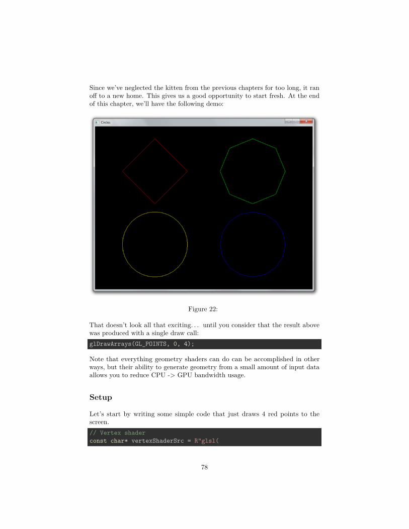
Since we’ve neglected the kitten from the previous chapters for too long, it ranoff to a new home. This gives us a good opportunity to start fresh. At the endof this chapter, we’ll have the following demo:
Figure 22:
That doesn’t look all that exciting. . . until you consider that the result abovewas produced with a single draw call:glDrawArrays(GL_POINTS, 0, 4);
Note that everything geometry shaders can do can be accomplished in otherways, but their ability to generate geometry from a small amount of input dataallows you to reduce CPU -> GPU bandwidth usage.
Setup
Let’s start by writing some simple code that just draws 4 red points to thescreen.// Vertex shaderconst char* vertexShaderSrc = R"glsl(
78
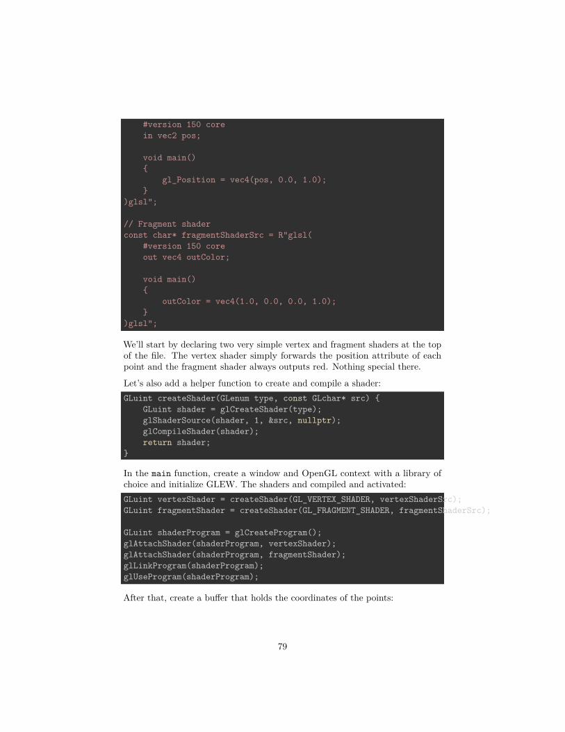
#version 150 corein vec2 pos;
void main(){
gl_Position = vec4(pos, 0.0, 1.0);}
)glsl";
// Fragment shaderconst char* fragmentShaderSrc = R"glsl(
#version 150 coreout vec4 outColor;
void main(){
outColor = vec4(1.0, 0.0, 0.0, 1.0);}
)glsl";
We’ll start by declaring two very simple vertex and fragment shaders at the topof the file. The vertex shader simply forwards the position attribute of eachpoint and the fragment shader always outputs red. Nothing special there.
Let’s also add a helper function to create and compile a shader:GLuint createShader(GLenum type, const GLchar* src) {
GLuint shader = glCreateShader(type);glShaderSource(shader, 1, &src, nullptr);glCompileShader(shader);return shader;
}
In the main function, create a window and OpenGL context with a library ofchoice and initialize GLEW. The shaders and compiled and activated:GLuint vertexShader = createShader(GL_VERTEX_SHADER, vertexShaderSrc);GLuint fragmentShader = createShader(GL_FRAGMENT_SHADER, fragmentShaderSrc);
GLuint shaderProgram = glCreateProgram();glAttachShader(shaderProgram, vertexShader);glAttachShader(shaderProgram, fragmentShader);glLinkProgram(shaderProgram);glUseProgram(shaderProgram);
After that, create a buffer that holds the coordinates of the points:
79
GLuint vbo;glGenBuffers(1, &vbo);
float points[] = {-0.45f, 0.45f,0.45f, 0.45f,0.45f, -0.45f,
-0.45f, -0.45f,};
glBindBuffer(GL_ARRAY_BUFFER, vbo);glBufferData(GL_ARRAY_BUFFER, sizeof(points), points, GL_STATIC_DRAW);
We have 4 points here, each with x and y device coordinates. Remember thatdevice coordinates range from -1 to 1 from left to right and bottom to top ofthe screen, so each corner will have a point.
Then create a VAO and set the vertex format specification:// Create VAOGLuint vao;glGenVertexArrays(1, &vao);glBindVertexArray(vao);
// Specify layout of point dataGLint posAttrib = glGetAttribLocation(shaderProgram, "pos");glEnableVertexAttribArray(posAttrib);glVertexAttribPointer(posAttrib, 2, GL_FLOAT, GL_FALSE, 0, 0);
And finally the render loop:glClearColor(0.0f, 0.0f, 0.0f, 1.0f);glClear(GL_COLOR_BUFFER_BIT);
glDrawArrays(GL_POINTS, 0, 4);
With this code, you should now see 4 red points on a black background as shownbelow:
If you are having problems, have a look at the reference source code.
Basic geometry shader
To understand how a geometry shader works, let’s look at an example:#version 150 core
80

Figure 23:
81

layout(points) in;layout(line_strip, max_vertices = 2) out;
void main(){
gl_Position = gl_in[0].gl_Position + vec4(-0.1, 0.0, 0.0, 0.0);EmitVertex();
gl_Position = gl_in[0].gl_Position + vec4(0.1, 0.0, 0.0, 0.0);EmitVertex();
EndPrimitive();}
Input types
Whereas a vertex shader processes vertices and a fragment shader processesfragments, a geometry shader processes entire primitives. The first line describeswhat kind of primitives our shader should process.layout(points) in;
The available types are listed below, along with their equivalent drawing commandtypes:
• points - GL_POINTS (1 vertex)• lines - GL_LINES, GL_LINE_STRIP, GL_LINE_LIST (2 vertices)• lines_adjacency - GL_LINES_ADJACENCY, GL_LINE_STRIP_ADJACENCY
(4 vertices)• triangles - GL_TRIANGLES, GL_TRIANGLE_STRIP, GL_TRIANGLE_FAN
(3 vertices)• triangles_adjacency - GL_TRIANGLES_ADJACENCY, GL_TRIANGLE_STRIP_ADJACENCY
(6 vertices)
Since we’re drawing GL_POINTS, the points type is appropriate.
Output types
The next line describes the output of the shader. What’s interesting aboutgeometry shaders is that they can output an entirely different type of geometryand the number of generated primitives can even vary!layout(line_strip, max_vertices = 2) out;
The second line specifies the output type and the maximum amount of verticesit can pass on. This is the maximum amount for the shader invocation, not for
82
a single primitive (line_strip in this case).
The following output types are available:
• points• line_strip• triangle_strip
These types seem somewhat restricted, but if you think about it, these types aresufficient to cover all possible types of primitives. For example, a triangle_stripwith only 3 vertices is equivalent to a regular triangle.
Vertex input
The gl_Position, as set in the vertex shader, can be accessed using the gl_inarray in the geometry shader. It is an array of structs that looks like this:in gl_PerVertex{
vec4 gl_Position;float gl_PointSize;float gl_ClipDistance[];
} gl_in[];
Notice that vertex attributes like pos and color are not included, we’ll lookinto accessing those later.
Vertex output
The geometry shader program can call two special functions to generate primi-tives, EmitVertex and EndPrimitive. Each time the program calls EmitVertex,a vertex is added to the current primitive. When all vertices have been added,the program calls EndPrimitive to generate the primitive.void main(){
gl_Position = gl_in[0].gl_Position + vec4(-0.1, 0.0, 0.0, 0.0);EmitVertex();
gl_Position = gl_in[0].gl_Position + vec4(0.1, 0.0, 0.0, 0.0);EmitVertex();
EndPrimitive();}
Before calling EmitVertex, the attributes of the vertex should be assigned tovariables like gl_Position, just like in the vertex shader. We’ll look at setting
83

attributes like color for the fragment shader later.
Now that you know the meaning of every line, can you explain what this geometricshader does?It creates a single horizontal line for each point coordinate passed to it.
Creating a geometry shader
There’s not much to explain, geometry shaders are created and activated inexactly the same way as other types of shaders. Let’s add a geometry shader toour 4 point sample that doesn’t do anything yet.const char* geometryShaderSrc = R"glsl(
#version 150 core
layout(points) in;layout(points, max_vertices = 1) out;
void main(){
gl_Position = gl_in[0].gl_Position;EmitVertex();EndPrimitive();
})glsl";
This geometry shader should be fairly straightforward. For each input point, itgenerates one equivalent output point. This is the minimum amount of codenecessary to still display the points on the screen.
With the helper function, creating a geometry shader is easy:GLuint geometryShader = createShader(GL_GEOMETRY_SHADER, geometryShaderSrc);
There’s nothing special about attaching it to the shader program either:glAttachShader(shaderProgram, geometryShader);
When you run the program now, it should still display the points as before.You can verify that the geometry shader is now doing its work by removing thecode from its main function. You’ll see that no points are being drawn anymore,because none are being generated!
Now, try replacing the geometry shader code with the line strip generating codefrom the previous section:#version 150 core
84

layout(points) in;layout(line_strip, max_vertices = 2) out;
void main(){
gl_Position = gl_in[0].gl_Position + vec4(-0.1, 0.0, 0.0, 0.0);EmitVertex();
gl_Position = gl_in[0].gl_Position + vec4(0.1, 0.0, 0.0, 0.0);EmitVertex();
EndPrimitive();}
Even though we’ve made no changes to our draw call, the GPU is suddenlydrawing tiny lines instead of points!
Figure 24:
Try experimenting a bit to get a feel for it. For example, try outputting rectanglesby using triangle_strip.
85
Geometry shaders and vertex attributes
Let’s add some variation to the lines that are being drawn by allowing each ofthem to have a unique color. By adding a color input variable to the vertexshader, we can specify a color per vertex and thus per generated line.#version 150 core
in vec2 pos;in vec3 color;
out vec3 vColor; // Output to geometry (or fragment) shader
void main(){
gl_Position = vec4(pos, 0.0, 1.0);vColor = color;
}
Update the vertex specification in the program code:GLint posAttrib = glGetAttribLocation(shaderProgram, "pos");glEnableVertexAttribArray(posAttrib);glVertexAttribPointer(posAttrib, 2, GL_FLOAT, GL_FALSE, 5 * sizeof(float), 0);
GLint colAttrib = glGetAttribLocation(shaderProgram, "color");glEnableVertexAttribArray(colAttrib);glVertexAttribPointer(colAttrib, 3, GL_FLOAT, GL_FALSE,
5 * sizeof(float), (void*) (2 * sizeof(float)));
And update the point data to include an RGB color per point:float points[] = {
-0.45f, 0.45f, 1.0f, 0.0f, 0.0f, // Red point0.45f, 0.45f, 0.0f, 1.0f, 0.0f, // Green point0.45f, -0.45f, 0.0f, 0.0f, 1.0f, // Blue point
-0.45f, -0.45f, 1.0f, 1.0f, 0.0f, // Yellow point};
Because the vertex shader is now not followed by a fragment shader, but ageometry shader, we have to handle the vColor variable as input there.#version 150 core
layout(points) in;layout(line_strip, max_vertices = 2) out;
in vec3 vColor[]; // Output from vertex shader for each vertex
86

out vec3 fColor; // Output to fragment shader
void main(){
...
You can see that it is very similar to how inputs are handled in the fragmentshader. The only difference is that inputs must be arrays now, because thegeometry shader can receive primitives with multiple vertices as input, each withits own attribute values.
Because the color needs to be passed further down to the fragment shader, weadd it as output of the geometry shader. We can now assign values to it, justlike we did earlier with gl_Position.void main(){
fColor = vColor[0]; // Point has only one vertex
gl_Position = gl_in[0].gl_Position + vec4(-0.1, 0.1, 0.0, 0.0);EmitVertex();
gl_Position = gl_in[0].gl_Position + vec4(0.1, 0.1, 0.0, 0.0);EmitVertex();
EndPrimitive();}
Whenever EmitVertex is called now, a vertex is emitted with the current valueof fColor as color attribute. We can now access that attribute in the fragmentshader:#version 150 core
in vec3 fColor;
out vec4 outColor;
void main(){
outColor = vec4(fColor, 1.0);}
So, when you specify an attribute for a vertex, it is first passed to the vertexshader as input. The vertex shader can then choose to output it to the geometryshader. And then the geometry shader can choose to further output it to thefragment shader.
87

Figure 25:
88

However, this demo is not very interesting. We could easily replicate thisbehaviour by creating a vertex buffer with a single line and issuing a couple ofdraw calls with different colors and positions set with uniform variables.
Dynamically generating geometry
The real power of geometry shader lies in the ability to generate a varyingamount of primitives, so let’s create a demo that properly abuses this ability.
Let’s say you’re making a game where the world consists of circles. You coulddraw a single model of a circle and repeatedly draw it, but this approach is notideal. If you’re too close, these “circles” will look like ugly polygons and if you’retoo far away, your graphics card is wasting performance on rendering complexityyou can’t even see.
We can do better with geometry shaders! We can write a shader that generatesthe appropriate resolution circle based on run-time conditions. Let’s first modifythe geometry shader to draw a 10-sided polygon at each point. If you rememberyour trigonometry, it should be a piece of cake:#version 150 core
layout(points) in;layout(line_strip, max_vertices = 11) out;
in vec3 vColor[];out vec3 fColor;
const float PI = 3.1415926;
void main(){
fColor = vColor[0];
for (int i = 0; i <= 10; i++) {// Angle between each side in radiansfloat ang = PI * 2.0 / 10.0 * i;
// Offset from center of point (0.3 to accomodate for aspect ratio)vec4 offset = vec4(cos(ang) * 0.3, -sin(ang) * 0.4, 0.0, 0.0);gl_Position = gl_in[0].gl_Position + offset;
EmitVertex();}
EndPrimitive();
89
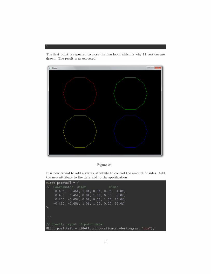
}
The first point is repeated to close the line loop, which is why 11 vertices aredrawn. The result is as expected:
Figure 26:
It is now trivial to add a vertex attribute to control the amount of sides. Addthe new attribute to the data and to the specification:float points[] = {// Coordinates Color Sides
-0.45f, 0.45f, 1.0f, 0.0f, 0.0f, 4.0f,0.45f, 0.45f, 0.0f, 1.0f, 0.0f, 8.0f,0.45f, -0.45f, 0.0f, 0.0f, 1.0f, 16.0f,
-0.45f, -0.45f, 1.0f, 1.0f, 0.0f, 32.0f};
...
// Specify layout of point dataGLint posAttrib = glGetAttribLocation(shaderProgram, "pos");
90

glEnableVertexAttribArray(posAttrib);glVertexAttribPointer(posAttrib, 2, GL_FLOAT, GL_FALSE,
6 * sizeof(float), 0);
GLint colAttrib = glGetAttribLocation(shaderProgram, "color");glEnableVertexAttribArray(colAttrib);glVertexAttribPointer(colAttrib, 3, GL_FLOAT, GL_FALSE,
6 * sizeof(float), (void*) (2 * sizeof(float)));
GLint sidesAttrib = glGetAttribLocation(shaderProgram, "sides");glEnableVertexAttribArray(sidesAttrib);glVertexAttribPointer(sidesAttrib, 1, GL_FLOAT, GL_FALSE,
6 * sizeof(float), (void*) (5 * sizeof(float)));
Alter the vertex shader to pass the value to the geometry shader:#version 150 core
in vec2 pos;in vec3 color;in float sides;
out vec3 vColor;out float vSides;
void main(){
gl_Position = vec4(pos, 0.0, 1.0);vColor = color;vSides = sides;
}
And use the variable in the geometry shader instead of the magic number ofsides 10.0. It’s also necessary to set an appropriate max_vertices value for ourinput, otherwise the circles with more vertices will be cut off.layout(line_strip, max_vertices = 64) out;
...
in float vSides[];
...
// Safe, floats can represent small integers exactlyfor (int i = 0; i <= vSides[0]; i++) {
// Angle between each side in radians
91
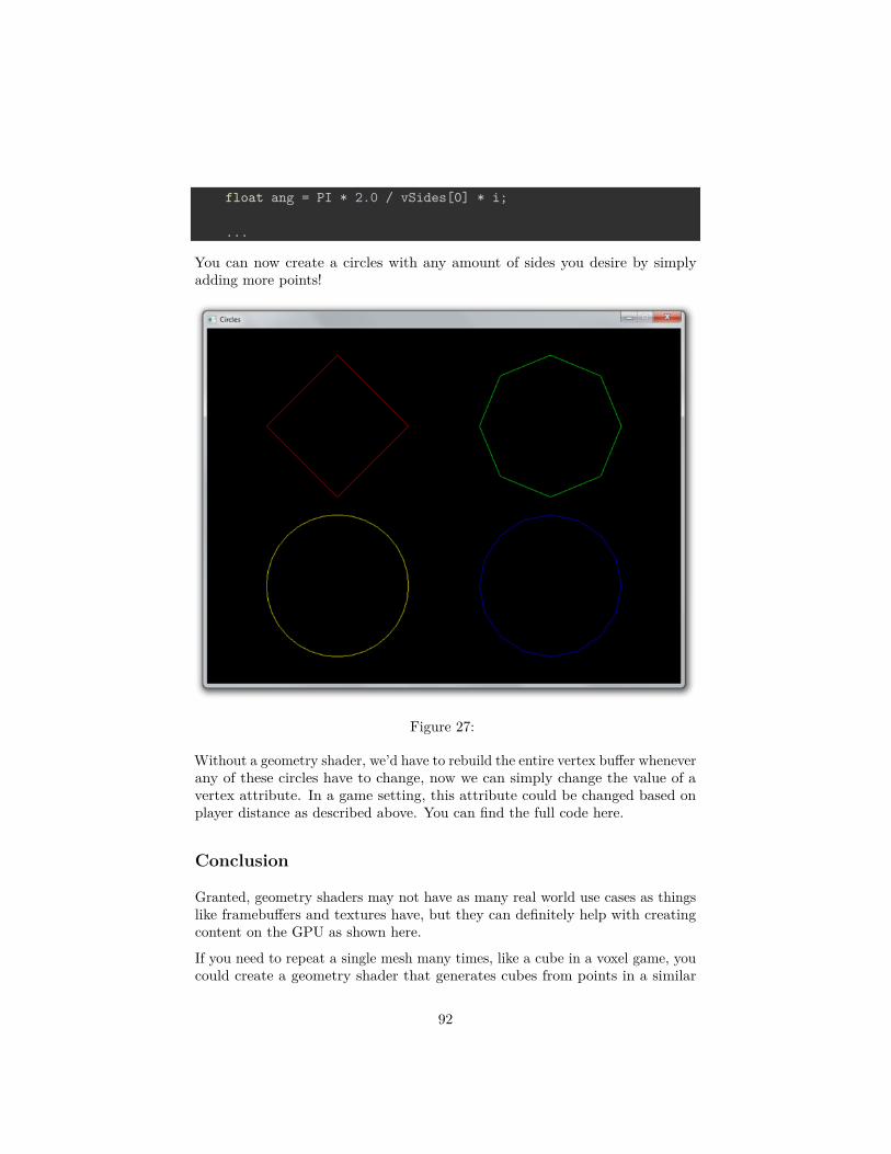
float ang = PI * 2.0 / vSides[0] * i;
...
You can now create a circles with any amount of sides you desire by simplyadding more points!
Figure 27:
Without a geometry shader, we’d have to rebuild the entire vertex buffer wheneverany of these circles have to change, now we can simply change the value of avertex attribute. In a game setting, this attribute could be changed based onplayer distance as described above. You can find the full code here.
Conclusion
Granted, geometry shaders may not have as many real world use cases as thingslike framebuffers and textures have, but they can definitely help with creatingcontent on the GPU as shown here.
If you need to repeat a single mesh many times, like a cube in a voxel game, youcould create a geometry shader that generates cubes from points in a similar
92

fashion. However, for these cases where each generated mesh is exactly the same,there are more efficient methods like instancing.
Lastly, with regards to portability, the latest WebGL and OpenGL ES standardsdo not yet support geometry shaders, so keep that in mind if you’re consideringthe development of a mobile or web application.
Exercises
• Try using a geometry shader in a 3D scenario to create more complexmeshes like cubes from points. (Solution)
Transform feedback
Up until now we’ve always sent vertex data to the graphics processor and onlyproduced drawn pixels in framebuffers in return. What if we want to retrievethe vertices after they’ve passed through the vertex or geometry shaders? Inthis chapter we’ll look at a way to do this, known as transform feedback.
So far, we’ve used VBOs (Vertex Buffer Objects) to store vertices to be usedfor drawing operations. The transform feedback extension allows shaders towrite vertices back to these as well. You could for example build a vertex shaderthat simulates gravity and writes updated vertex positions back to the buffer.This way you don’t have to transfer this data back and forth from graphicsmemory to main memory. On top of that, you get to benefit from the vastparallel processing power of today’s GPUs.
Basic feedback
We’ll start from scratch so that the final program will clearly demonstrate howsimple transform feedback is. Unfortunately there’s no preview this time, becausewe’re not going to draw anything in this chapter! Although this feature can beused to simplify effects like particle simulation, explaining these is a bit beyondthe scope of these articles. After you’ve understood the basics of transformfeedback, you’ll be able to find and understand plenty of articles around the webon these topics.
Let’s start with a simple vertex shader.const GLchar* vertexShaderSrc = R"glsl(
in float inValue;out float outValue;
void main()
93
{outValue = sqrt(inValue);
})glsl";
This vertex shader does not appear to make much sense. It doesn’t set agl_Position and it only takes a single arbitrary float as input. Luckily, we canuse transform feedback to capture the result, as we’ll see momentarily.GLuint shader = glCreateShader(GL_VERTEX_SHADER);glShaderSource(shader, 1, &vertexShaderSrc, nullptr);glCompileShader(shader);
GLuint program = glCreateProgram();glAttachShader(program, shader);
Compile the shader, create a program and attach the shader, but don’t callglLinkProgram yet! Before linking the program, we have to tell OpenGL whichoutput attributes we want to capture into a buffer.const GLchar* feedbackVaryings[] = { "outValue" };glTransformFeedbackVaryings(program, 1, feedbackVaryings, GL_INTERLEAVED_ATTRIBS);
The first parameter is self-explanatory, the second and third parameter specifythe length of the output names array and the array itself, and the final parameterspecifies how the data should be written.
The following two formats are available:
• GL_INTERLEAVED_ATTRIBS: Write all attributes to a singlebuffer object.
• GL_SEPARATE_ATTRIBS: Writes attributes to multiple buffer ob-jects or at different offsets into a buffer.
Sometimes it is useful to have separate buffers for each attribute, but lets keepit simple for this demo. Now that you’ve specified the output variables, you canlink and activate the program. That is because the linking process depends onknowledge about the outputs.glLinkProgram(program);glUseProgram(program);
After that, create and bind the VAO:GLuint vao;glGenVertexArrays(1, &vao);glBindVertexArray(vao);
Now, create a buffer with some input data for the vertex shader:
94

GLfloat data[] = { 1.0f, 2.0f, 3.0f, 4.0f, 5.0f };
GLuint vbo;glGenBuffers(1, &vbo);glBindBuffer(GL_ARRAY_BUFFER, vbo);glBufferData(GL_ARRAY_BUFFER, sizeof(data), data, GL_STATIC_DRAW);
The numbers in data are the numbers we want the shader to calculate the squareroot of and transform feedback will help us get the results back.
With regards to vertex pointers, you know the drill by now:GLint inputAttrib = glGetAttribLocation(program, "inValue");glEnableVertexAttribArray(inputAttrib);glVertexAttribPointer(inputAttrib, 1, GL_FLOAT, GL_FALSE, 0, 0);
Transform feedback will return the values of outValue, but first we’ll need tocreate a VBO to hold these, just like the input vertices:GLuint tbo;glGenBuffers(1, &tbo);glBindBuffer(GL_ARRAY_BUFFER, tbo);glBufferData(GL_ARRAY_BUFFER, sizeof(data), nullptr, GL_STATIC_READ);
Notice that we now pass a nullptr to create a buffer big enough to hold all ofthe resulting floats, but without specifying any initial data. The appropriateusage type is now GL_STATIC_READ, which indicates that we intend OpenGL towrite to this buffer and our application to read from it. (See reference for usagetypes)
We’ve now made all preparations for the rendering computation process. As wedon’t intend to draw anything, the rasterizer should be disabled:glEnable(GL_RASTERIZER_DISCARD);
To actually bind the buffer we’ve created above as transform feedback buffer, wehave to use a new function called glBindBufferBase.glBindBufferBase(GL_TRANSFORM_FEEDBACK_BUFFER, 0, tbo);
The first parameter is currently required to be GL_TRANSFORM_FEEDBACK_BUFFERto allow for future extensions. The second parameter is the index of the outputvariable, which is simply 0 because we only have one. The final parameterspecifies the buffer object to bind.
Before doing the draw call, you have to enter transform feedback mode:glBeginTransformFeedback(GL_POINTS);
It certainly brings back memories of the old glBegin days! Just like the geometry
95

shader in the last chapter, the possible values for the primitive mode are a bitmore limited.
• GL_POINTS — GL_POINTS• GL_LINES — GL_LINES, GL_LINE_LOOP, GL_LINE_STRIP, GL_LINES_ADJACENCY,
GL_LINE_STRIP_ADJACENCY• GL_TRIANGLES — GL_TRIANGLES, GL_TRIANGLE_STRIP, GL_TRIANGLE_FAN,
GL_TRIANGLES_ADJACENCY, GL_TRIANGLE_STRIP_ADJACENCY
If you only have a vertex shader, as we do now, the primitive must match theone being drawn:glDrawArrays(GL_POINTS, 0, 5);
Even though we’re now working with data, the single numbers can still be seenas separate “points”, so we use that primitive mode.
End the transform feedback mode:glEndTransformFeedback();
Normally, at the end of a drawing operation, we’d swap the buffers to presentthe result on the screen. We still want to make sure the rendering operationhas finished before trying to access the results, so we flush OpenGL’s commandbuffer:glFlush();
Getting the results back is now as easy as copying the buffer data back to anarray:GLfloat feedback[5];glGetBufferSubData(GL_TRANSFORM_FEEDBACK_BUFFER, 0, sizeof(feedback), feedback);
If you now print the values in the array, you should see the square roots of theinput in your terminal:printf("%f %f %f %f %f\n", feedback[0], feedback[1], feedback[2], feedback[3], feedback[4]);
Figure 28:
96
Congratulations, you now know how to make your GPU perform general purposetasks with vertex shaders! Of course a real GPGPU framework like OpenCL isgenerally better at this, but the advantage of transform feedback is that you candirectly repurpose the data in drawing operations, by for example binding thetransform feedback buffer as array buffer and performing normal drawing calls.
If you have a graphics card and driver that supports it, you could also usecompute shaders in OpenGL 4.3 instead, which were actually designed for tasksthat are less related to drawing.
You can find the full code here.
Feedback transform and geometry shaders
When you include a geometry shader, the transform feedback operation willcapture the outputs of the geometry shader instead of the vertex shader. Forexample:// Vertex shaderconst GLchar* vertexShaderSrc = R"glsl(
in float inValue;out float geoValue;
void main(){
geoValue = sqrt(inValue);}
)glsl";
// Geometry shaderconst GLchar* geoShaderSrc = R"glsl(
layout(points) in;layout(triangle_strip, max_vertices = 3) out;
in float[] geoValue;out float outValue;
void main(){
for (int i = 0; i < 3; i++) {outValue = geoValue[0] + i;EmitVertex();
}
EndPrimitive();}
97

)glsl";
The geometry shader takes a point processed by the vertex shader and generates2 more to form a triangle with each point having a 1 higher value.GLuint geoShader = glCreateShader(GL_GEOMETRY_SHADER);glShaderSource(geoShader, 1, &geoShaderSrc, nullptr);glCompileShader(geoShader);
...
glAttachShader(program, geoShader);
Compile and attach the geometry shader to the program to start using it.const GLchar* feedbackVaryings[] = { "outValue" };glTransformFeedbackVaryings(program, 1, feedbackVaryings, GL_INTERLEAVED_ATTRIBS);
Although the output is now coming from the geometry shader, we’ve not changedthe name, so this code remains unchanged.
Because each input vertex will generate 3 vertices as output, the transformfeedback buffer now needs to be 3 times as big as the input buffer:glBufferData(GL_ARRAY_BUFFER, sizeof(data) * 3, nullptr, GL_STATIC_READ);
When using a geometry shader, the primitive specified to glBeginTransformFeedbackmust match the output type of the geometry shader:glBeginTransformFeedback(GL_TRIANGLES);
Retrieving the output still works the same:// Fetch and print resultsGLfloat feedback[15];glGetBufferSubData(GL_TRANSFORM_FEEDBACK_BUFFER, 0, sizeof(feedback), feedback);
for (int i = 0; i < 15; i++) {printf("%f\n", feedback[i]);
}
Although you have to pay attention to the feedback primitive type and the sizeof your buffers, adding a geometry shader to the equation doesn’t change muchother than the shader responsible for output.
The full code can be found here.
98

Figure 29:
Variable feedback
As we’ve seen in the previous chapter, geometry shaders have the unique propertyto generate a variable amount of data. Luckily, there are ways to keep track ofhow many primitives were written by using query objects.
Just like all the other objects in OpenGL, you’ll have to create one first:GLuint query;glGenQueries(1, &query);
Then, right before calling glBeginTransformFeedback, you have to tell OpenGLto keep track of the number of primitives written:glBeginQuery(GL_TRANSFORM_FEEDBACK_PRIMITIVES_WRITTEN, query);
After glEndTransformFeedback, you can stop “recording”:glEndQuery(GL_TRANSFORM_FEEDBACK_PRIMITIVES_WRITTEN);
Retrieving the result is done as follows:GLuint primitives;glGetQueryObjectuiv(query, GL_QUERY_RESULT, &primitives);
99

You can then print that value along with the other data:printf("%u primitives written!\n\n", primitives);
Figure 30:
Notice that it returns the number of primitives, not the number of vertices. Sincewe have 15 vertices, with each triangle having 3, we have 5 primitives.
Query objects can also be used to record things such as GL_PRIMITIVES_GENERATEDwhen dealing with just geometry shaders and GL_TIME_ELAPSED to measuretime spent on the server (graphics card) doing work.
See the full code if you got stuck somewhere on the way.
Conclusion
You now know enough about geometry shaders and transform feedback to makeyour graphics card do some very interesting work besides just drawing! You caneven combine transform feedback and rasterization to update vertices and drawthem at the same time!
100

Exercises
• Try writing a vertex shader that simulates gravity to make points hoveraround the mouse cursor using transform feedback to update the vertices.(Solution)
101