Embed Size (px)
Citation preview
TM3160TM3200TM3240
MODELS:
I S E K I T R A C T O R S
ISEKI TRACTORS
1
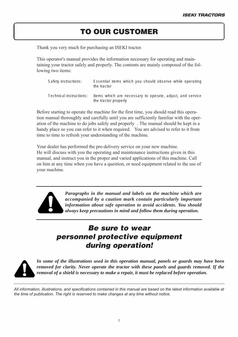
Thank you very much for purchasing an ISEKI tractor.
This operator's manual provides the information necessary for operating and main-taining your tractor safely and properly. The contents are mainly composed of the fol-lowing two items:
Safety instructions: Essential items which you should observe while operating the tractor
Technical instructions: Items which are necessary to operate, adjust, and service the tractor properly
Before starting to operate the machine for the first time, you should read this opera-tion manual thoroughly and carefully until you are sufficiently familiar with the oper-ation of the machine to do jobs safely and properly . The manual should be kept in ahandy place so you can refer to it when required. You are advised to refer to it fromtime to time to refresh your understanding of the machine.
Your dealer has performed the pre-delivery service on your new machine.He will discuss with you the operating and maintenance instructions given in thismanual, and instruct you in the proper and varied applications of this machine. Callon him at any time when you have a question, or need equipment related to the use ofyour machine.
TO OUR CUSTOMER
In some of the illustrations used in this operation manual, panels or guards may have beenremoved for clarity. Never operate the tractor with these panels and guards removed. If theremoval of a shield is necessary to make a repair, it must be replaced before operation.
All information, illustrations, and specifications contained in this manual are based on the latest information available atthe time of publication. The right is reserved to make changes at any time without notice.
Paragraphs in the manual and labels on the machine which areaccompanied by a caution mark contain particularly importantinformation about safe operation to avoid accidents. You shouldalways keep precautions in mind and follow them during operation.
Be sure to wearpersonnel protective equipment
during operation!
TM3160F,TM3200F&TM3240F
2
TO OUR CUSTOMER ................................................... 1
TABLE OF CONTENTS ............................................... 2
SAFETY ........................................................................ 4
PERSONAL SAFETY INSTRUCTIONS ........................ 4MAKING YOUR TRACTOR A SAFE VEHICLE ............ 4U HOW TO MAINTAIN SAFETY ................................ 4U DIMENSIONAL LIMITS OF IMPLEMENTS ............ 6FOR SAFE OPERATION .............................................. 7U HOW TO BE A SAFE OPERATOR ......................... 7U WHEN ANOTHER PERSON OPERATES............... 8U BEFORE OPERATION ........................................... 8U STARTING ENGINE AND MOVING TRACTOR ..... 9U WHEN TRAVELLING .............................................. 9U LOADING ONTO OR UNLOADING
FROM A TRUCK .....................................................11U DURING OPERATION ............................................12U INSPECTION AND MAINTENANCE ......................13U STORAGE ...............................................................14MAINTENANCE OF THE ELECTRIC SYSTEM ...........15U TO MAINTAIN ELECTRIC WIRING ........................15U TO HANDLE THE BATTERY ..................................15U TO HANDLE BOOSTER CABLES ..........................16U SAFETY DECALS ...................................................16U SAFETY DECALS AND THEIR LOCATION ...........17
TRACTOR IDENTIFICATION .......................................21
MODEL / SERIAL NUMBERS .................................21
MAJOR COMPONENTS ..............................................22
INSTRUMENTS & CONTROLS ...................................23
INSTRUMENT PANEL ............................................24Electrical Fuel Shut-Off .....................................25Main Switch .......................................................25Indicator Light Strip ...........................................25Tachometer .......................................................26
SWITCHES .............................................................26MAIN CLUTCH PEDAL ...........................................27BRAKES ..................................................................27
Brake Pedals .....................................................27Parking Brakes ..................................................27
ENGINE SPEED CONTROLS ................................28TRAVEL CONTROL LEVERS ................................28POWER TAKE-OFF (PTO) SWITCH (HST) ...........28REMOTE HYDRAULIC CYLINDER CONTROLSWITCH (OPTION) .................................................29OTHER CONTROLS ...............................................29
OPERATION .................................................................30
BRAEK-IN PERIOD ................................................30STARTING ..............................................................30
Pre-Start Inspection ..........................................30Normal Starting .................................................31Restarting Warm Engine ...................................32Cold Weather Starting .......................................32Warm-Up Period ...............................................32Operator Observations ......................................32
MECHANICAL TRANSMISSION ............................30Ground Speed Selection ...................................33Stopping Tractor ...............................................34
HYDROSTATIC TRANSMISSION ..........................35Ground Speed Selection ...................................35Stopping Tractor ...............................................36
DIFFERENTIAL LOCK OPERATION ......................37FOUR-WHEEL DRIVE ............................................37POWER TAKE-OFF (PTO) .....................................39
Rear PTO Shaft ................................................39Mid PTO Shaft ..................................................40
PTO OPERATING CONTROLS ..............................40THREE-POINT HITCH ............................................42
Hitch Controls ...................................................42Rear Linkage .....................................................43Attaching implements ........................................44Using Position Control ......................................45Detaching Implements ......................................46
LUBRICATION & PERIODIC MAINTENANCE ............47
SPECIFICATIONS & CAPACITIES ........................47Engine Oil .........................................................47Engine Coolant .................................................47Fuel Tank ..........................................................47Transmission & Differential Housing(Including Hydraulic System) ............................47Front Axle ..........................................................47Grease Fittings ..................................................47
LUBRICATION / FILL POINTS ...............................49PERIODIC MAINTENANCE SCHEDULE ...............52LUBRICATION DETAILS ........................................53
Grease Fittings ..................................................53SERVICE ACCESS .................................................53
Engine Oil & Filter .............................................55Transmission Oil & Filters .................................56Hydrostatic Cartridge Oil Filter Replacement ....58Front Axle Oil ....................................................58
COOLING SYSTEM ................................................59ENGINE AIR CLEANER .........................................60FUEL SYSTEM .......................................................61
Fuel Filter ..........................................................61Air-bleeding Procedure .....................................62Throttle Lever ....................................................63
ELECTRICAL SYSTEM ..........................................64Battery ...............................................................64Starting Switches ..............................................65
TABLE OF CONTENTS
ISEKI TRACTORS
3
Wiring / Fuse Arrangement ...............................66WIRING DIAGRAM .................................................66CLUTCH FREE-PLAY ADJUSTMENT ...................67BRAKE FREE-PLAY ADJUSTMENT ......................68
Hydrostatic transmission ...................................69WHEELS & TYRES .................................................70
Tyre Inflation Pressures ....................................70Wheel Bolt Torque ............................................70Front Wheel Spacing ........................................70Rear Wheel Spacing .........................................71Steering Free-Play ............................................71Front Axle End-Float .........................................72
CLUTCH HOUSING PLUG .....................................72TORQUE CHART ...................................................72STORAGE ...............................................................73
TROUBLESHOOTING ..................................................74
Engine .....................................................................74Clutch ......................................................................74Brakes .....................................................................76Hydraulic System ....................................................76Steering System ......................................................77Electrical System .....................................................77
SPECIFICATIONS ........................................................79
Mechanical transmission.............................................79Engine ...............................................................79Transmission .....................................................79Power take-off (PTO) ........................................79Hydraulics .........................................................80Electrical system ...............................................80Capacities .........................................................80Tread width settings ..........................................80Maximum axle loading ......................................80
GENERAL DIMENSIONS .......................................81Hydrostatic transmission .............................................82
Engine ...............................................................82Transmission .....................................................82Power take-off (PTO) ........................................82Hydraulics .........................................................83Electrical system ...............................................83Capacities .........................................................83Tread width settings ..........................................83Maximum axle loading ......................................83
GENERAL DIMENSIONS .......................................84
ASSEMBLY & PRE-DELIVERY INSPECTION ............85
WIRING DIAGRAM .......................................................91
TM3160F,TM3200F&TM3240F
4
PERSONAL SAFETY INSTRUCTIONS
Whenever you see the words and symbols below ,used in this Operator's Instruction Book and ondecals, you MUST take note of their instructions asthey relate to personal safety.
DANGER: This symbol together with theword DANGER indicates an imminently haz-ardous situation that, if not avoided, willresult in DEATH OR VERY SERIOUS INJURY.
WARNING: This symbol together with theword WARNING indicates a potentially haz-ardous situation that, if not avoided, couldresult in DEATH OR VERY SERIOUS INJURY.
CAUTION: This symbol together with theword CAUTION is used to indicate a poten-tially hazardous situation that, if not avoided,may result in MINOR INJURY.
IMPORTANT: The word IMPORTANT is used to identify special instruction or procedures which, if not strictly observed, could result in dam-age to, or destruction of the machine, process or its surrounding.
NOTE: The word NOTE is used to indicate points of particular interest for more efficient and conven-ient repair or operation.
Understand thoroughly the following precautions,always keep them in mind before, during, and afteroperation, and never take chances.
MAKING YOUR TRACTOR A SAFEVEHICLE
HOW TO MAINTAIN SAFETY
(1) Never attempt to do the following: Modification of the structure of the tractor Installation of other type engine Installation of tires of other than the original tire size.
Any malfunctions or failures of the tractor due to unauthorized modification are not covered by the warranty.
SAFETY
SAFETY
5
(2) This machine cannot be driven on a public road without authorization by a local government agency, etc.
When transporting an unauthorized machine on a public road, load it on a truck.
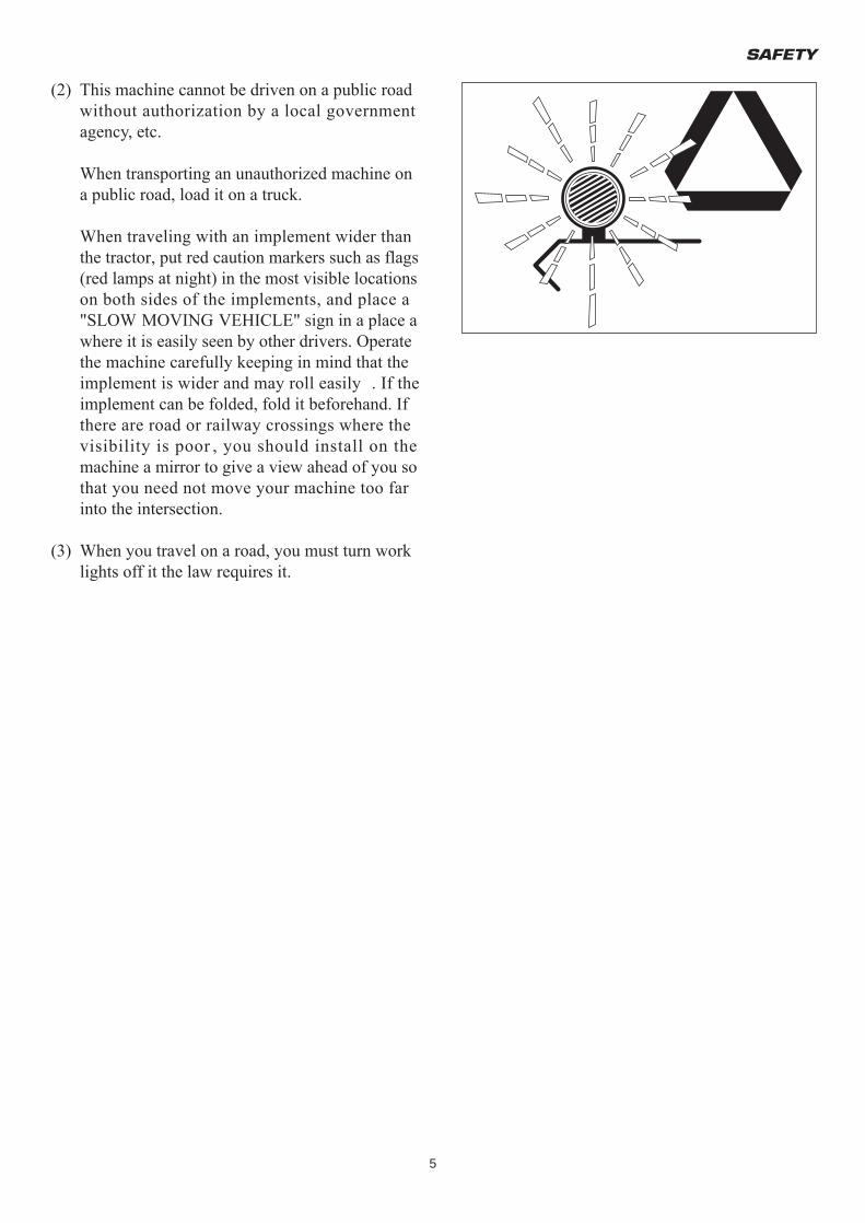
When traveling with an implement wider than the tractor, put red caution markers such as flags (red lamps at night) in the most visible locations on both sides of the implements, and place a "SLOW MOVING VEHICLE" sign in a place a where it is easily seen by other drivers. Operate the machine carefully keeping in mind that the implement is wider and may roll easily . If the implement can be folded, fold it beforehand. If there are road or railway crossings where the visibility is poor , you should install on the machine a mirror to give a view ahead of you so that you need not move your machine too far into the intersection.
(3) When you travel on a road, you must turn work lights off it the law requires it.
TM3160F,TM3200F&TM3240F
6
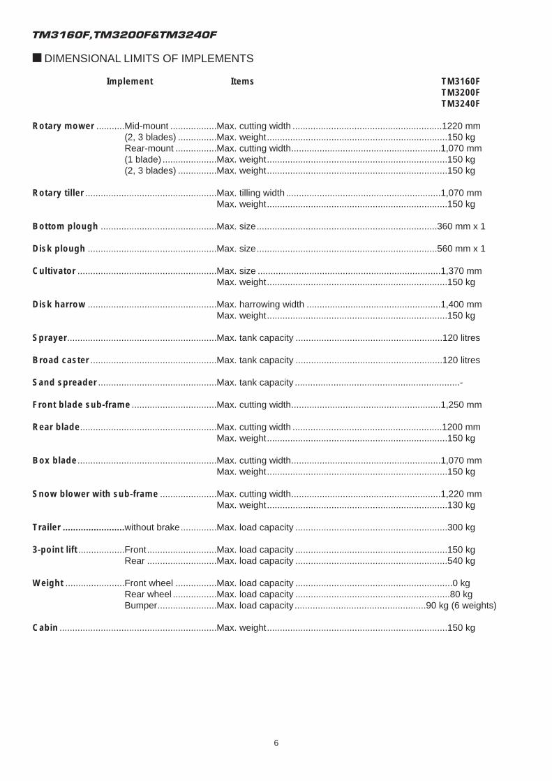
U DIMENSIONAL LIMITS OF IMPLEMENTS
Implement Items TM3160FTM3200FTM3240F
Rotary mower ...........Mid-mount ..................Max. cutting width ..........................................................1220 mm(2, 3 blades) ...............Max. weight......................................................................150 kgRear-mount ................Max. cutting width..........................................................1,070 mm(1 blade) .....................Max. weight......................................................................150 kg(2, 3 blades) ...............Max. weight......................................................................150 kg
Rotary tiller ...................................................Max. tilling width ............................................................1,070 mmMax. weight......................................................................150 kg
Bottom plough .............................................Max. size......................................................................360 mm x 1
Disk plough ..................................................Max. size......................................................................560 mm x 1
Cultivator ......................................................Max. size .......................................................................1,370 mmMax. weight......................................................................150 kg
Disk harrow ..................................................Max. harrowing width ....................................................1,400 mmMax. weight......................................................................150 kg
Sprayer..........................................................Max. tank capacity .........................................................120 litres
Broad caster .................................................Max. tank capacity .........................................................120 litres
Sand spreader ..............................................Max. tank capacity ................................................................-
Front blade sub-frame .................................Max. cutting width..........................................................1,250 mm
Rear blade.....................................................Max. cutting width ..........................................................1200 mmMax. weight......................................................................150 kg
Box blade......................................................Max. cutting width..........................................................1,070 mmMax. weight......................................................................150 kg
Snow blower with sub-frame ......................Max. cutting width..........................................................1,220 mmMax. weight......................................................................130 kg
Trailer ........................without brake..............Max. load capacity ...........................................................300 kg
3-point lift ..................Front...........................Max. load capacity ...........................................................150 kgRear ...........................Max. load capacity ...........................................................540 kg
Weight .......................Front wheel ................Max. load capacity .............................................................0 kgRear wheel .................Max. load capacity ............................................................80 kgBumper.......................Max. load capacity ...................................................90 kg (6 weights)
Cabin .............................................................Max. weight......................................................................150 kg
SAFETY
7
FOR SAFE OPERATION
U HOW TO BE A SAFE OPERATOR
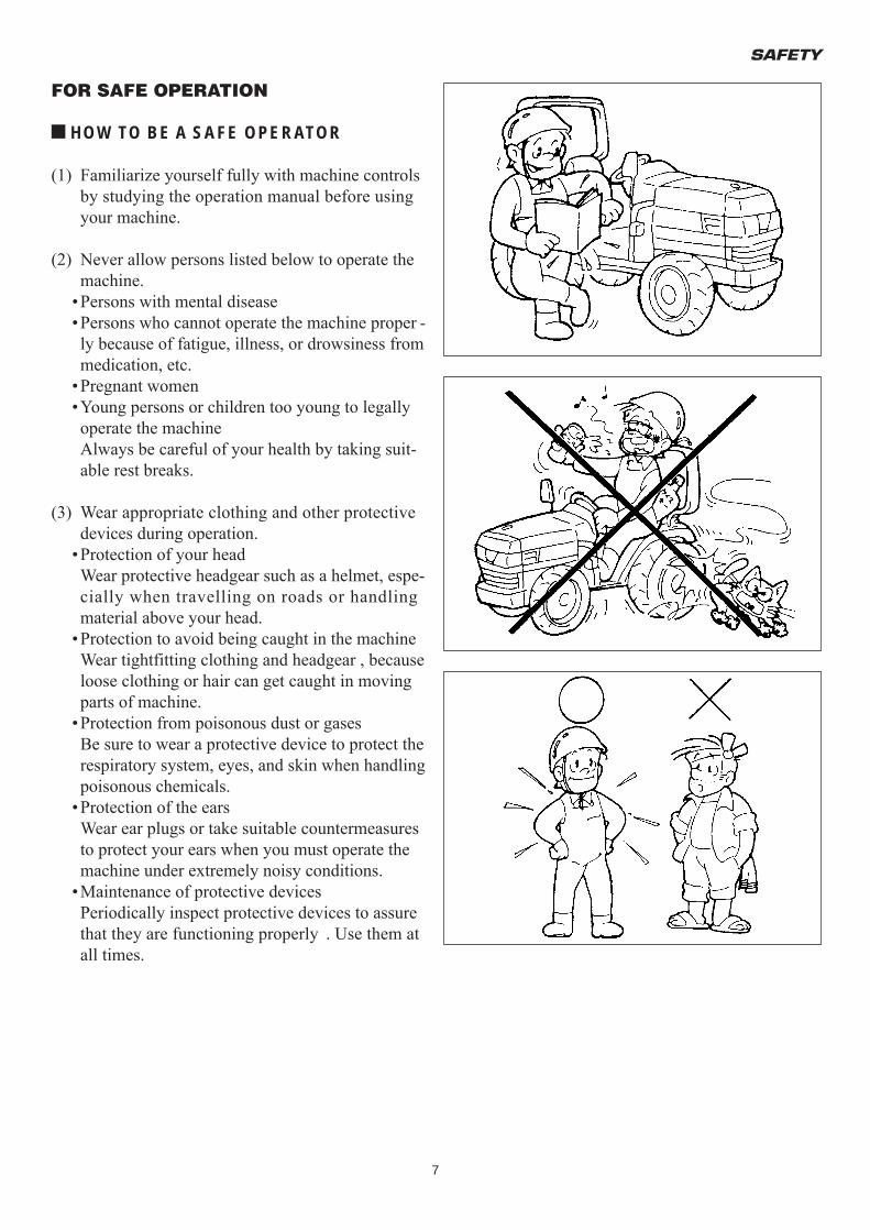
(1) Familiarize yourself fully with machine controls by studying the operation manual before using your machine.
(2) Never allow persons listed below to operate the machine.
•Persons with mental disease•Persons who cannot operate the machine proper -ly because of fatigue, illness, or drowsiness from medication, etc.
•Pregnant women•Young persons or children too young to legally operate the machineAlways be careful of your health by taking suit-able rest breaks.
(3) Wear appropriate clothing and other protective devices during operation.
•Protection of your headWear protective headgear such as a helmet, espe-cially when travelling on roads or handling material above your head.
•Protection to avoid being caught in the machineWear tightfitting clothing and headgear , because loose clothing or hair can get caught in moving parts of machine.
•Protection from poisonous dust or gasesBe sure to wear a protective device to protect the respiratory system, eyes, and skin when handling poisonous chemicals.
•Protection of the earsWear ear plugs or take suitable countermeasures to protect your ears when you must operate the machine under extremely noisy conditions.
•Maintenance of protective devicesPeriodically inspect protective devices to assure that they are functioning properly . Use them at all times.
TM3160F,TM3200F&TM3240F
8
U WHEN ANOTHER PERSON OPERATESYOUR MACHINE
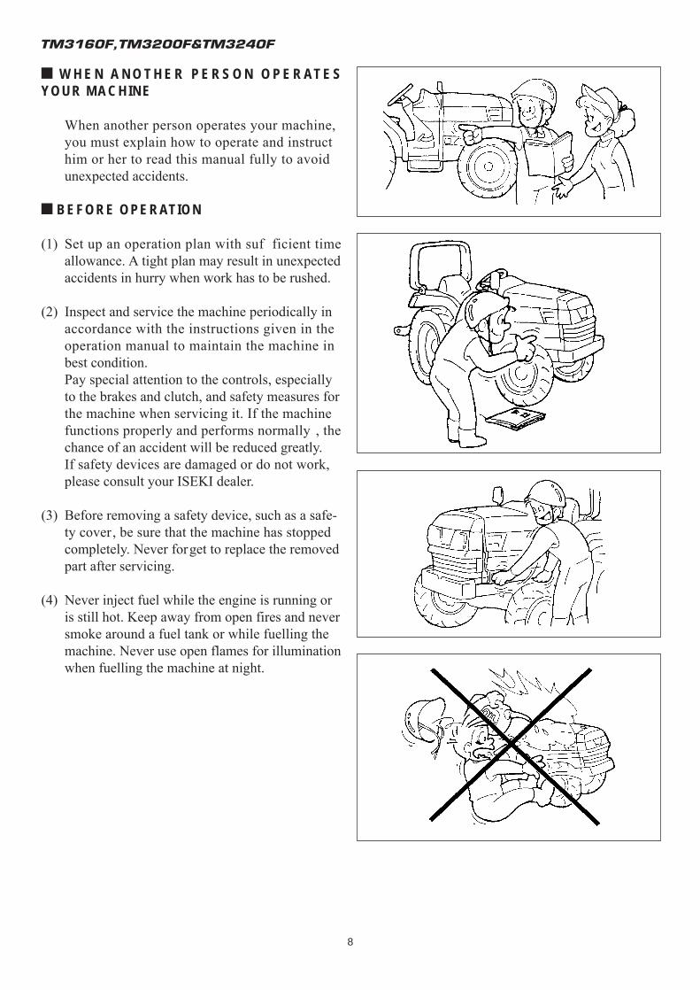
When another person operates your machine, you must explain how to operate and instruct him or her to read this manual fully to avoid unexpected accidents.
U BEFORE OPERATION
(1) Set up an operation plan with suf ficient time allowance. A tight plan may result in unexpected accidents in hurry when work has to be rushed.
(2) Inspect and service the machine periodically in accordance with the instructions given in the operation manual to maintain the machine in best condition.Pay special attention to the controls, especially to the brakes and clutch, and safety measures for the machine when servicing it. If the machine functions properly and performs normally , the chance of an accident will be reduced greatly.If safety devices are damaged or do not work, please consult your ISEKI dealer.
(3) Before removing a safety device, such as a safe-ty cover, be sure that the machine has stopped completely. Never forget to replace the removed part after servicing.
(4) Never inject fuel while the engine is running or is still hot. Keep away from open fires and never smoke around a fuel tank or while fuelling the machine. Never use open flames for illumination when fuelling the machine at night.
SAFETY
9
U STARTING ENGINE AND MOVING TRAC-TOR
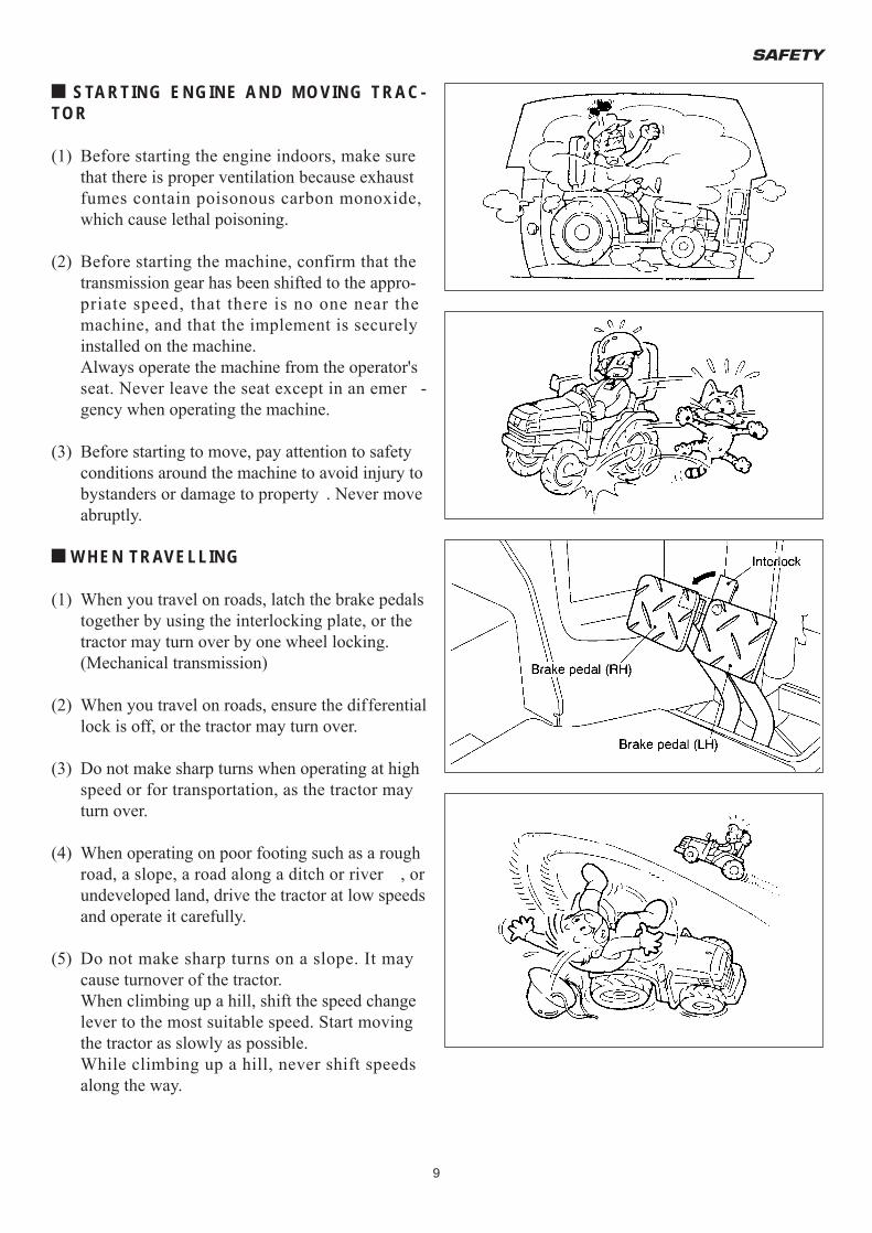
(1) Before starting the engine indoors, make sure that there is proper ventilation because exhaust fumes contain poisonous carbon monoxide, which cause lethal poisoning.
(2) Before starting the machine, confirm that the transmission gear has been shifted to the appro-priate speed, that there is no one near the machine, and that the implement is securely installed on the machine.Always operate the machine from the operator's seat. Never leave the seat except in an emer -gency when operating the machine.
(3) Before starting to move, pay attention to safety conditions around the machine to avoid injury to bystanders or damage to property . Never move abruptly.
U WHEN TRAVELLING
(1) When you travel on roads, latch the brake pedals together by using the interlocking plate, or the tractor may turn over by one wheel locking.(Mechanical transmission)
(2) When you travel on roads, ensure the differential lock is off, or the tractor may turn over.
(3) Do not make sharp turns when operating at high speed or for transportation, as the tractor may turn over.
(4) When operating on poor footing such as a rough road, a slope, a road along a ditch or river , or undeveloped land, drive the tractor at low speeds and operate it carefully.
(5) Do not make sharp turns on a slope. It may cause turnover of the tractor.When climbing up a hill, shift the speed change lever to the most suitable speed. Start moving the tractor as slowly as possible.While climbing up a hill, never shift speeds along the way.
TM3160F,TM3200F&TM3240F
10
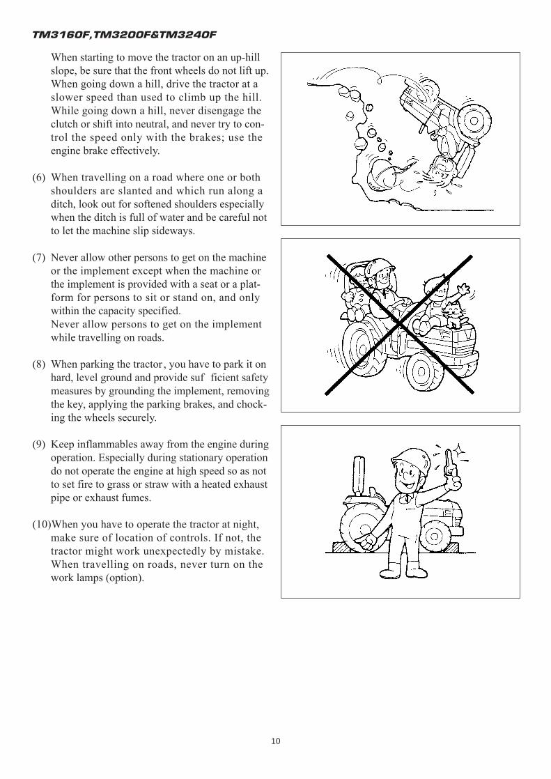
When starting to move the tractor on an up-hill slope, be sure that the front wheels do not lift up.When going down a hill, drive the tractor at a slower speed than used to climb up the hill. While going down a hill, never disengage the clutch or shift into neutral, and never try to con-trol the speed only with the brakes; use the engine brake effectively.
(6) When travelling on a road where one or both shoulders are slanted and which run along a ditch, look out for softened shoulders especially when the ditch is full of water and be careful not to let the machine slip sideways.
(7) Never allow other persons to get on the machine or the implement except when the machine or the implement is provided with a seat or a plat-form for persons to sit or stand on, and only within the capacity specified.Never allow persons to get on the implement while travelling on roads.
(8) When parking the tractor , you have to park it on hard, level ground and provide suf ficient safety measures by grounding the implement, removing the key, applying the parking brakes, and chock-ing the wheels securely.
(9) Keep inflammables away from the engine during operation. Especially during stationary operation do not operate the engine at high speed so as not to set fire to grass or straw with a heated exhaust pipe or exhaust fumes.
(10)When you have to operate the tractor at night, make sure of location of controls. If not, the tractor might work unexpectedly by mistake. When travelling on roads, never turn on the work lamps (option).
SAFETY
11
U LOADING ONTO OR UNLOADING FROM ATRUCK
(1) When loading the tractor onto a truck or a trailer, turn off the truck's engine and apply the parking brakes to the truck or the trailer . Otherwise, the truck could move and the tractor fall to the ground.
(2) Pay sufficient attention to the safety conditions around the tractor and have it guided by some-one to assist the operation. Never allow other persons to approach the tractor , especially in front of or behind it.
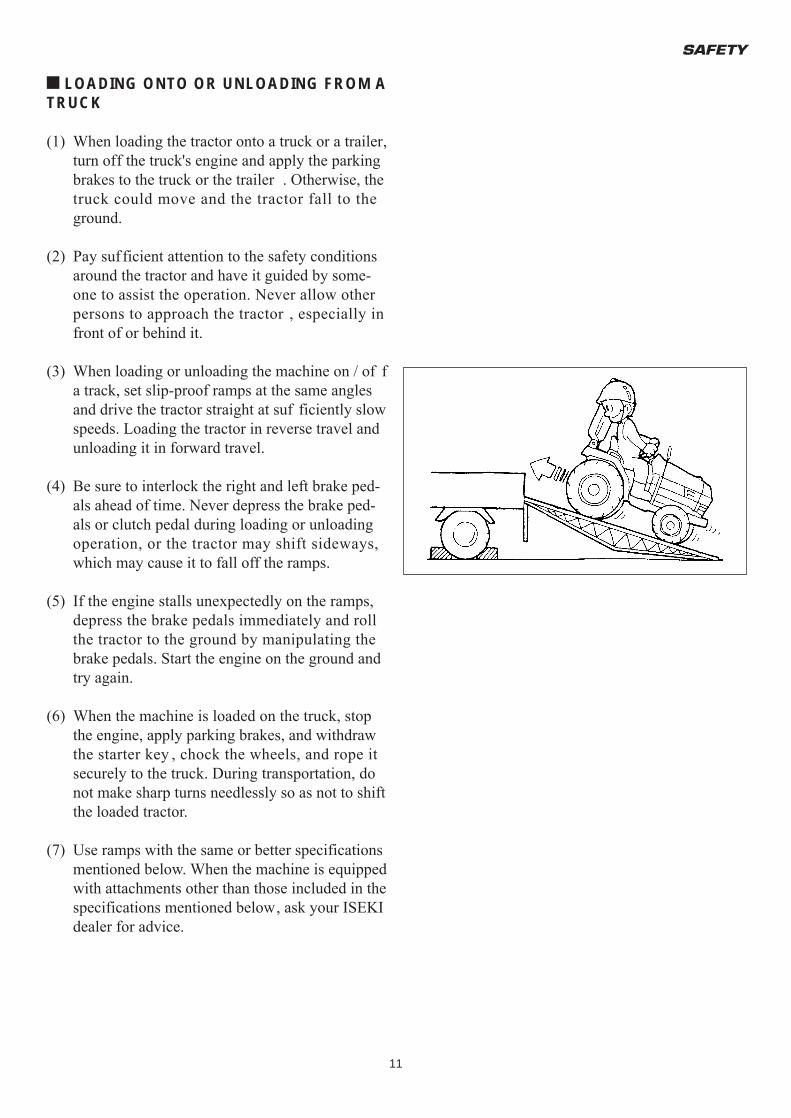
(3) When loading or unloading the machine on / of f a track, set slip-proof ramps at the same angles and drive the tractor straight at suf ficiently slow speeds. Loading the tractor in reverse travel and unloading it in forward travel.
(4) Be sure to interlock the right and left brake ped-als ahead of time. Never depress the brake ped-als or clutch pedal during loading or unloading operation, or the tractor may shift sideways, which may cause it to fall off the ramps.
(5) If the engine stalls unexpectedly on the ramps, depress the brake pedals immediately and roll the tractor to the ground by manipulating the brake pedals. Start the engine on the ground and try again.
(6) When the machine is loaded on the truck, stop the engine, apply parking brakes, and withdraw the starter key , chock the wheels, and rope it securely to the truck. During transportation, do not make sharp turns needlessly so as not to shift the loaded tractor.
(7) Use ramps with the same or better specifications mentioned below. When the machine is equipped with attachments other than those included in the specifications mentioned below, ask your ISEKI dealer for advice.
TM3160F,TM3200F&TM3240F
12
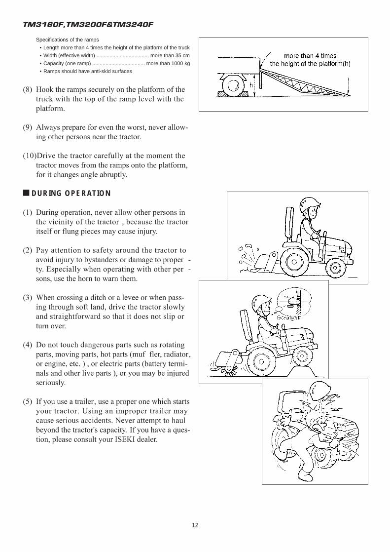
Specifications of the ramps
• Length more than 4 times the height of the platform of the truck
• Width (effective width) .................................... more than 35 cm
• Capacity (one ramp) .................................... more than 1000 kg
• Ramps should have anti-skid surfaces
(8) Hook the ramps securely on the platform of the truck with the top of the ramp level with the platform.
(9) Always prepare for even the worst, never allow-ing other persons near the tractor.
(10)Drive the tractor carefully at the moment the tractor moves from the ramps onto the platform, for it changes angle abruptly.
U DURING OPERATION
(1) During operation, never allow other persons in the vicinity of the tractor , because the tractor itself or flung pieces may cause injury.
(2) Pay attention to safety around the tractor to avoid injury to bystanders or damage to proper -ty. Especially when operating with other per -sons, use the horn to warn them.
(3) When crossing a ditch or a levee or when pass-ing through soft land, drive the tractor slowly and straightforward so that it does not slip or turn over.
(4) Do not touch dangerous parts such as rotating parts, moving parts, hot parts (muf fler, radiator, or engine, etc. ) , or electric parts (battery termi-nals and other live parts ), or you may be injured seriously.
(5) If you use a trailer, use a proper one which starts your tractor. Using an improper trailer may cause serious accidents. Never attempt to haul beyond the tractor's capacity. If you have a ques-tion, please consult your ISEKI dealer.
SAFETY
13
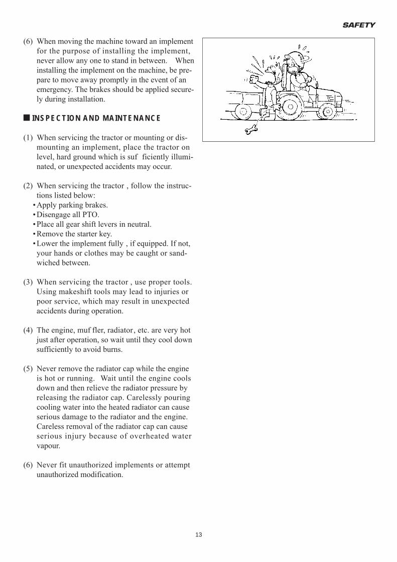
(6) When moving the machine toward an implement for the purpose of installing the implement, never allow any one to stand in between. When installing the implement on the machine, be pre-pare to move away promptly in the event of an emergency. The brakes should be applied secure-ly during installation.
U INSPECTION AND MAINTENANCE
(1) When servicing the tractor or mounting or dis-mounting an implement, place the tractor on level, hard ground which is suf ficiently illumi-nated, or unexpected accidents may occur.
(2) When servicing the tractor , follow the instruc-tions listed below:
•Apply parking brakes.•Disengage all PTO.•Place all gear shift levers in neutral.•Remove the starter key.•Lower the implement fully , if equipped. If not, your hands or clothes may be caught or sand-wiched between.
(3) When servicing the tractor , use proper tools. Using makeshift tools may lead to injuries or poor service, which may result in unexpected accidents during operation.
(4) The engine, muf fler, radiator, etc. are very hot just after operation, so wait until they cool down sufficiently to avoid burns.
(5) Never remove the radiator cap while the engine is hot or running. Wait until the engine cools down and then relieve the radiator pressure by releasing the radiator cap. Carelessly pouring cooling water into the heated radiator can cause serious damage to the radiator and the engine. Careless removal of the radiator cap can cause serious injury because of overheated water vapour.
(6) Never fit unauthorized implements or attempt unauthorized modification.
TM3160F,TM3200F&TM3240F
14
(7) Be sure to reinstall the removed safety covers in place as exposed dangerous parts may cause serious injury.
(8) Avoid high-pressure fluids. Escaping fluid under pressure can penetrate the skin and cause serious injury, so keep hands and body away from pin holes and nozzles ejecting such fluids. Be sure to consult your dealer about the hydraulic and fuel injection system trouble.When checking for leaks, use a piece of cardboard or wood without fail.If any hydraulic fluid is injected accidentally into the skin, it must be removed within a few hours by a doctor familiar with this type of injury.
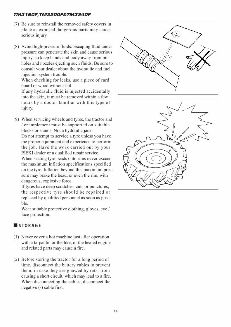
(9) When servicing wheels and tyres, the tractor and / or implement must be supported on suitable blocks or stands. Not a hydraulic jack.Do not attempt to service a tyre unless you have the proper equipment and experience to perform the job. Have the work carried out by your ISEKI dealer or a qualified repair service.When seating tyre beads onto rims never exceed the maximum inflation specifications specified on the tyre. Inflation beyond this maximum pres-sure may brake the bead, or even the rim, with dangerous, explosive force.If tyres have deep scratches, cuts or punctures, the respective tyre should be repaired or replaced by qualified personnel as soon as possi-ble.Wear suitable protective clothing, gloves, eye / face protection.
U STORAGE
(1) Never cover a hot machine just after operation with a tarpaulin or the like, or the heated engine and related parts may cause a fire.
(2) Before storing the tractor for a long period of time, disconnect the battery cables to prevent them, in case they are gnawed by rats, from causing a short circuit, which may lead to a fire. When disconnecting the cables, disconnect the negative (-) cable first.
SAFETY
15
(3) Safe storage of dangerous objects•When storing dangerous implements, take appropriate safety measures to prevent accidents by covering with tarpaulin.
•Store fuel in a safe place with caution signs such as "PREVENT FIRE" or "INFLAMMABLE."
•All inflammables must also be stored in a safe, fire-resistant location.
MAINTENANCE OF THE ELECTRICSYSTEM
U TO MAINTAIN ELECTRIC WIRING
(1) When servicing the electric wiring, stop the engine without fail. Otherwise your hands or clothes may be caught in or sandwiched between rotating parts.
(2) Before manipulating electric parts, be sure to disconnect the earth battery cable (-), or you may get an electric shock or be injured by sparks.
(3) Loose electric terminals or connectors may not only lower electrical performance but also cause short circuit or leakage of electricity , which may lead to a fire. Promptly repair or replace dam-aged wiring.
(4) Remove chaff or dust from the battery , wiring, muffler, or engine. Otherwise it could result a fire.
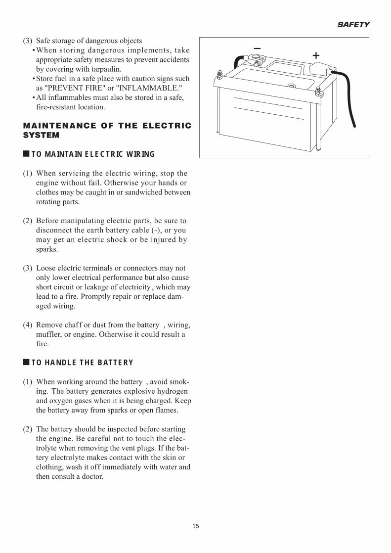
U TO HANDLE THE BATTERY
(1) When working around the battery , avoid smok-ing. The battery generates explosive hydrogen and oxygen gases when it is being charged. Keep the battery away from sparks or open flames.
(2) The battery should be inspected before starting the engine. Be careful not to touch the elec-trolyte when removing the vent plugs. If the bat-tery electrolyte makes contact with the skin or clothing, wash it off immediately with water and then consult a doctor.
TM3160F,TM3200F&TM3240F
16
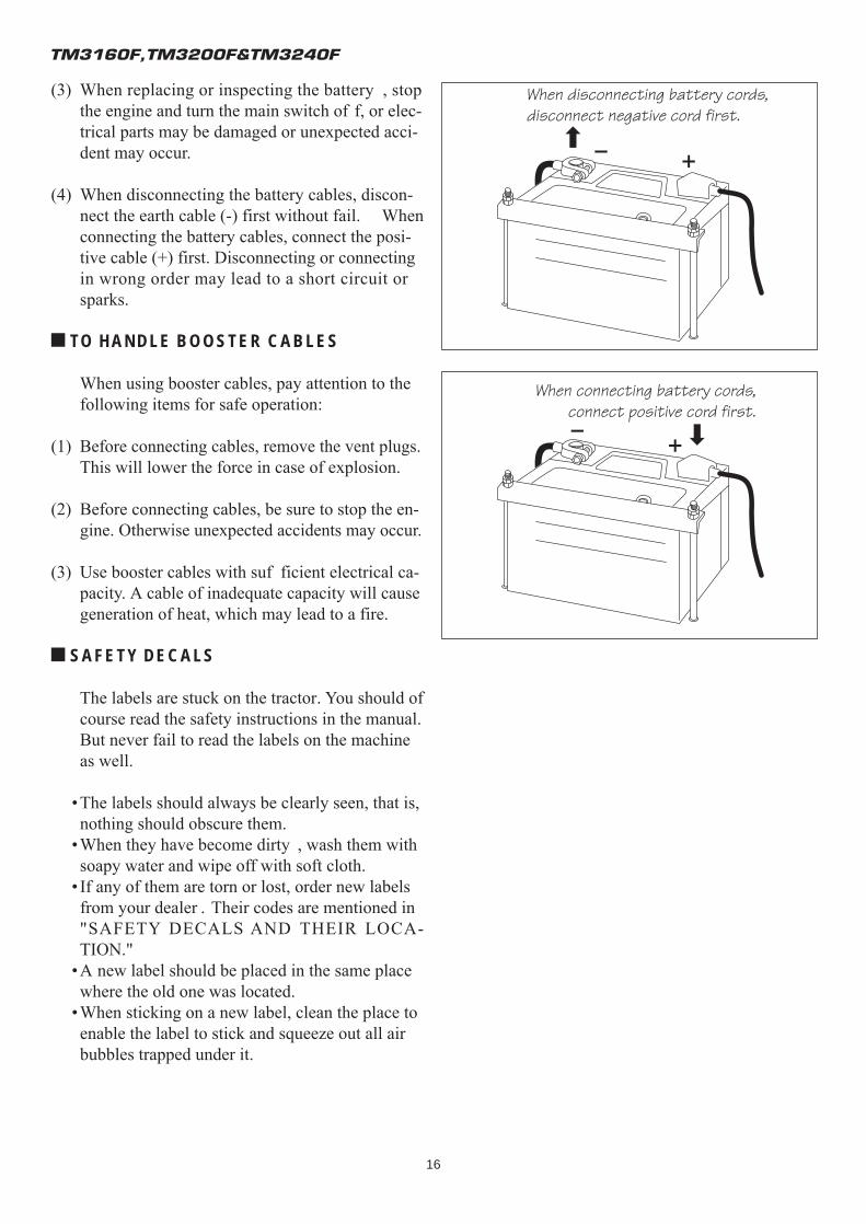
(3) When replacing or inspecting the battery , stop the engine and turn the main switch of f, or elec-trical parts may be damaged or unexpected acci-dent may occur.
(4) When disconnecting the battery cables, discon-nect the earth cable (-) first without fail. When connecting the battery cables, connect the posi-tive cable (+) first. Disconnecting or connecting in wrong order may lead to a short circuit or sparks.
U TO HANDLE BOOSTER CABLES
When using booster cables, pay attention to the following items for safe operation:
(1) Before connecting cables, remove the vent plugs.This will lower the force in case of explosion.
(2) Before connecting cables, be sure to stop the en-gine. Otherwise unexpected accidents may occur.
(3) Use booster cables with suf ficient electrical ca-pacity. A cable of inadequate capacity will cause generation of heat, which may lead to a fire.
U SAFETY DECALS
The labels are stuck on the tractor. You should of course read the safety instructions in the manual. But never fail to read the labels on the machine as well.
•The labels should always be clearly seen, that is, nothing should obscure them.
•When they have become dirty , wash them with soapy water and wipe off with soft cloth.
• If any of them are torn or lost, order new labels from your dealer . Their codes are mentioned in "SAFETY DECALS AND THEIR LOCA-TION."
•A new label should be placed in the same place where the old one was located.
•When sticking on a new label, clean the place to enable the label to stick and squeeze out all air bubbles trapped under it.
When disconnecting battery cords,disconnect negative cord first.
When connecting battery cords,connect positive cord first.
SAFETY
17
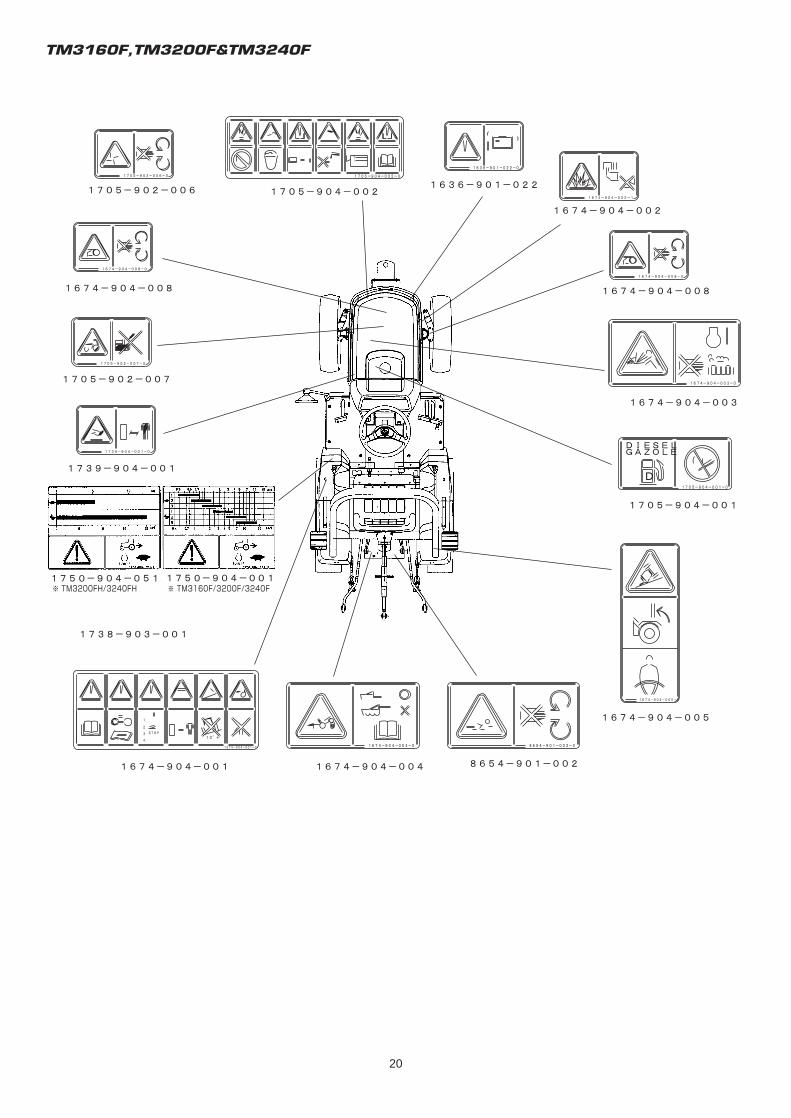
SAFETY DECALS AND THEIR LOCATIONS
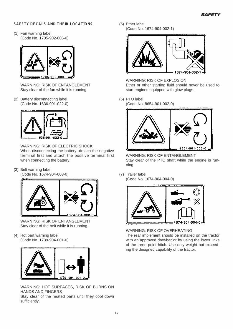
(1) Fan warning label(Code No. 1705-902-006-0)
WARNING: RISK OF ENTANGLEMENTStay clear of the fan while it is running.
(2) Battery disconnecting label(Code No. 1636-901-022-0)
WARNING: RISK OF ELECTRIC SHOCKWhen disconnecting the battery, detach the negative terminal first and attach the positive terminal first when connecting the battery.
(3) Belt warning label(Code No. 1674-904-008-0)
WARNING: RISK OF ENTANGLEMENTStay clear of the belt while it is running.
(4) Hot part warning label(Code No. 1739-904-001-0)
WARNING: HOT SURFACES, RISK OF BURNS ON HANDS AND FINGERSStay clear of the heated parts until they cool down sufficiently.
(5) Ether label(Code No. 1674-904-002-1)
WARNING: RISK OF EXPLOSIONEther or other starting fluid should never be used to start engines equipped with glow plugs.
(6) PTO label(Code No. 8654-901-002-0)
WARNING: RISK OF ENTANGLEMENTStay clear of the PTO shaft while the engine is run-ning.
(7) Trailer label(Code No. 1674-904-004-0)
WARNING: RISK OF OVERHEATINGThe rear implement should be installed on the tractor with an approved drawbar or by using the lower links of the three point hitch. Use only weight not exceed-ing the designed capability of the tractor.
TM3160F,TM3200F&TM3240F
18
(8) Radiator label(Code No. 1674-904-003-0)
WARNING: HIGH PRESSURE STEAM AND HOT WATERNever remove the radiator cap during or just after operation. The water in the radiator is very hot and highly pressurized, which could cause burns.
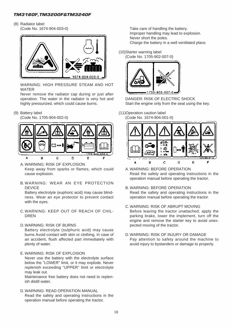
(9) Battery label(Code No. 1705-904-002-0)
A. WARNING: RISK OF EXPLOSIONKeep away from sparks or flames, which could cause explosion.
B. WARNING: WEAR AN EYE PROTECTION DEVICEBattery electrolyte (euphoric acid) may cause blind-ness. Wear an eye protector to prevent contact with the eyes.
C.WARNING: KEEP OUT OF REACH OF CHIL-DREN
D.WARNING: RISK OF BURNSBattery electrolyte (sulphuric acid) may cause burns Avoid contact with skin or clothing. In case of an accident, flush affected part immediately with plenty of water.
E. WARNING: RISK OF EXPLOSIONNever use the battery with the electrolyte surface below the "LOWER" limit, or it may explode. Never replenish exceeding "UPPER" limit or electrolyte may leak out.Maintenance free battery does not need to replen-ish distill water.
D.WARNING: READ OPERATION MANUALRead the safety and operating instructions in the operation manual before operating the tractor.
Take care of handling the battery.Improper handling may lead to explosion.Never short the poles.Charge the battery in a well ventilated place.
(10)Starter warning label(Code No. 1705-902-007-0)
DANGER: RISK OF ELECTRIC SHOCKStart the engine only from the seat using the key.
(11)Operation caution label(Code No. 1674-904-001-0)
A. WARNING: BEFORE OPERATIONRead the safety and operating instructions in the operation manual before operating the tractor.
B. WARNING: BEFORE OPERATIONRead the safety and operating instructions in the operation manual before operating the tractor.
C.WARNING: RISK OF ABRUPT MOVINGBefore leaving the tractor unattached, apply the parking brake, lower the implement, turn off the engine and remove the starter key to avoid unex-pected moving of the tractor.
D.WARNING: RISK OF INJURY OR DAMAGEPay attention to safety around the machine to avoid injury to bystanders or damage to properly.
SAFETY
19
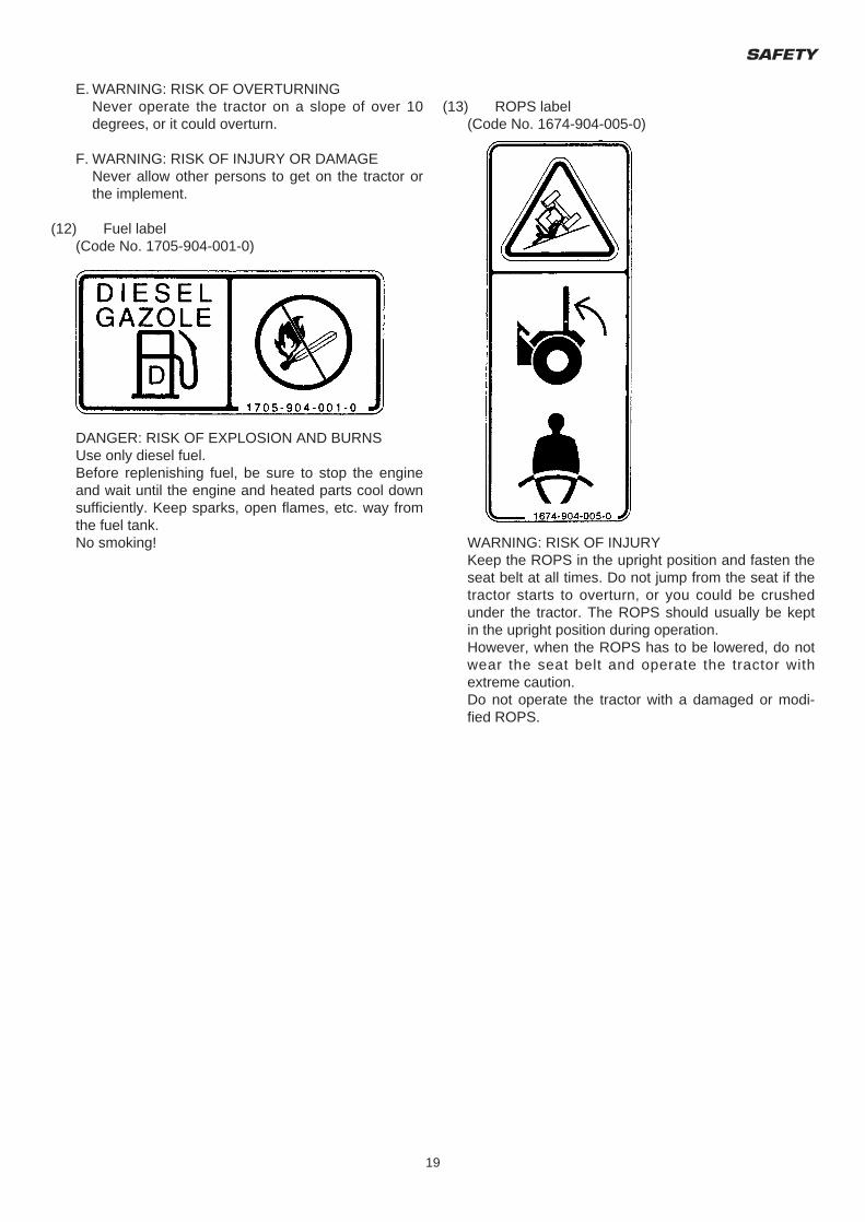
E. WARNING: RISK OF OVERTURNINGNever operate the tractor on a slope of over 10 degrees, or it could overturn.
F. WARNING: RISK OF INJURY OR DAMAGENever allow other persons to get on the tractor or the implement.
(12) Fuel label(Code No. 1705-904-001-0)
DANGER: RISK OF EXPLOSION AND BURNSUse only diesel fuel.Before replenishing fuel, be sure to stop the engine and wait until the engine and heated parts cool down sufficiently. Keep sparks, open flames, etc. way from the fuel tank.No smoking!
(13) ROPS label(Code No. 1674-904-005-0)
WARNING: RISK OF INJURYKeep the ROPS in the upright position and fasten the seat belt at all times. Do not jump from the seat if the tractor starts to overturn, or you could be crushed under the tractor. The ROPS should usually be kept in the upright position during operation.However, when the ROPS has to be lowered, do not wear the seat belt and operate the tractor with extreme caution.Do not operate the tractor with a damaged or modi-fied ROPS.
TM3160F,TM3200F&TM3240F
20
TRACTOR IDENTIFICATION
21
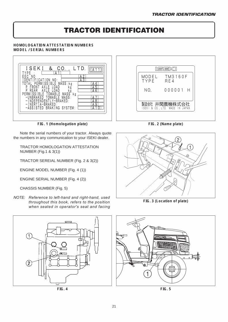
Note the serial numbers of your tractor. Always quotethe numbers in any communication to your ISEKI dealer.
TRACTOR HOMOLOGATION ATTESTATIONNUMBER (Fig.1 & 3(1))
TRACTOR SEREIAL NUMBER (Fig. 2 & 3(2))
ENGINE MODEL NUMBER (Fig. 4 (1))
ENGINE SERIAL NUMBER (Fig. 4 (2))
CHASSIS NUMBER (Fig. 5)
NOTE: Reference to left-hand and right-hand, used throughout this book, refers to the position when seated in operator's seat and facing
TRACTOR IDENTIFICATION
FIG. 2 (Name plate)FIG. 1 (Homologation plate)
HOMOLOGATION ATTESTATION NUMBERSMODEL / SERIAL NUMBERS
FIG. 3 (Location of plate)
FIG. 5FIG. 4
TM3160F,TM3200F&TM3240F MAJOR COMPONENTS
22
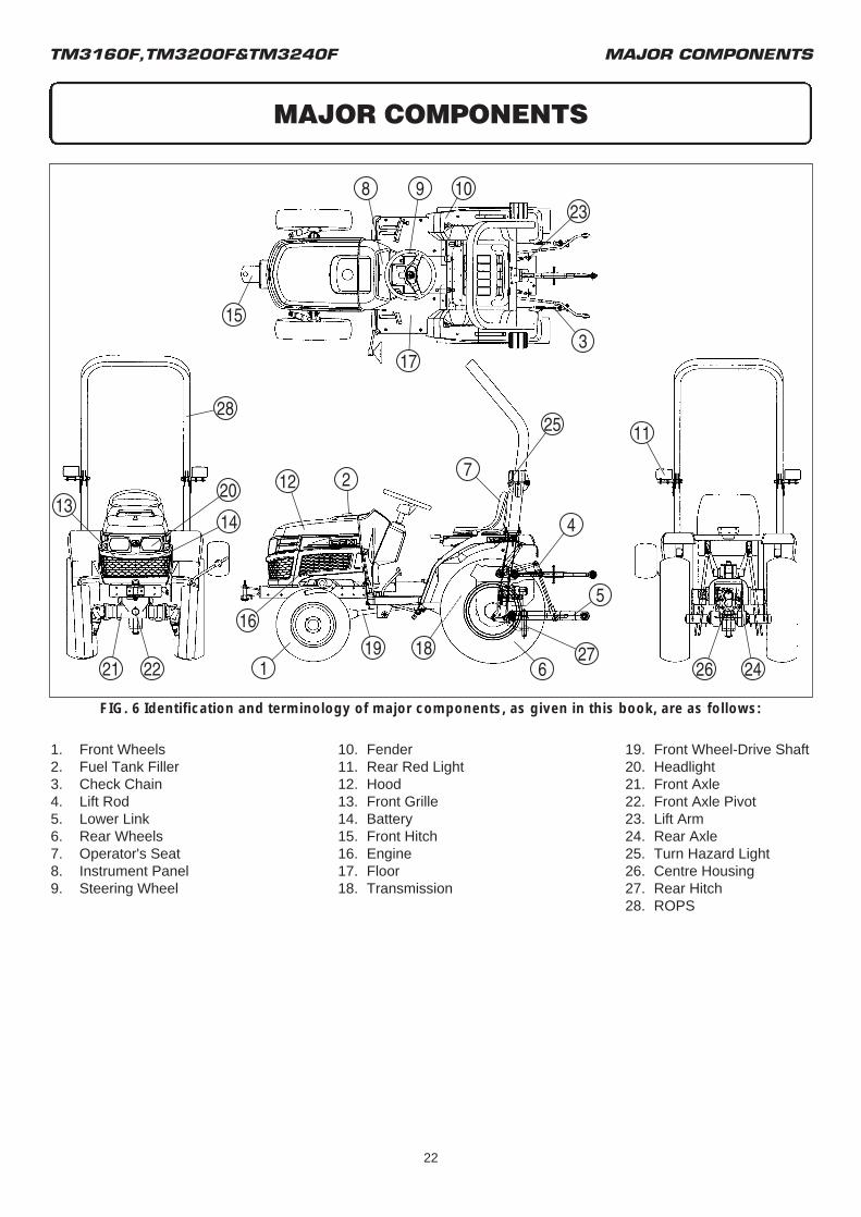
1. Front Wheels 10. Fender 19. Front Wheel-Drive Shaft2. Fuel Tank Filler 11. Rear Red Light 20. Headlight3. Check Chain 12. Hood 21. Front Axle4. Lift Rod 13. Front Grille 22. Front Axle Pivot5. Lower Link 14. Battery 23. Lift Arm6. Rear Wheels 15. Front Hitch 24. Rear Axle7. Operator's Seat 16. Engine 25. Turn Hazard Light8. Instrument Panel 17. Floor 26. Centre Housing9. Steering Wheel 18. Transmission 27. Rear Hitch
28. ROPS
FIG. 6 Identification and terminology of major components, as given in this book, are as follows:
MAJOR COMPONENTS
INSTRUMENTS & CONTROLS
23
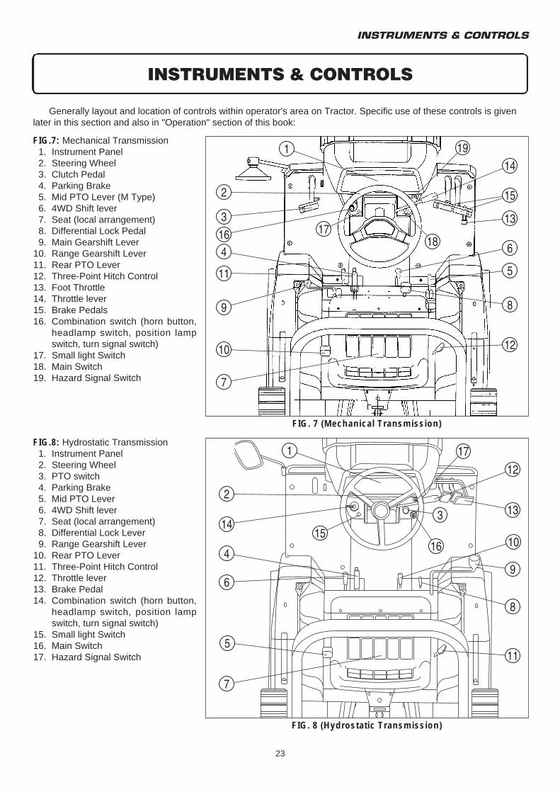
FIG.7: Mechanical Transmission1. Instrument Panel2. Steering Wheel3. Clutch Pedal4. Parking Brake5. Mid PTO Lever (M Type)6. 4WD Shift lever7. Seat (local arrangement)8. Differential Lock Pedal9. Main Gearshift Lever
10. Range Gearshift Lever11. Rear PTO Lever12. Three-Point Hitch Control13. Foot Throttle14. Throttle lever15. Brake Pedals16. Combination switch (horn button,
headlamp switch, position lamp switch, turn signal switch)
17. Small light Switch18. Main Switch19. Hazard Signal Switch
Generally layout and location of controls within operator's area on Tractor. Specific use of these controls is givenlater in this section and also in "Operation" section of this book:
INSTRUMENTS & CONTROLS
FIG. 7 (Mechanical Transmission)
FIG. 8 (Hydrostatic Transmission)
FIG.8: Hydrostatic Transmission1. Instrument Panel2. Steering Wheel3. PTO switch4. Parking Brake5. Mid PTO Lever6. 4WD Shift lever7. Seat (local arrangement)8. Differential Lock Lever9. Range Gearshift Lever
10. Rear PTO Lever11. Three-Point Hitch Control12. Throttle lever13. Brake Pedal14. Combination switch (horn button,
headlamp switch, position lamp switch, turn signal switch)
15. Small light Switch16. Main Switch17. Hazard Signal Switch
TM3160F,TM3200F&TM3240F
24
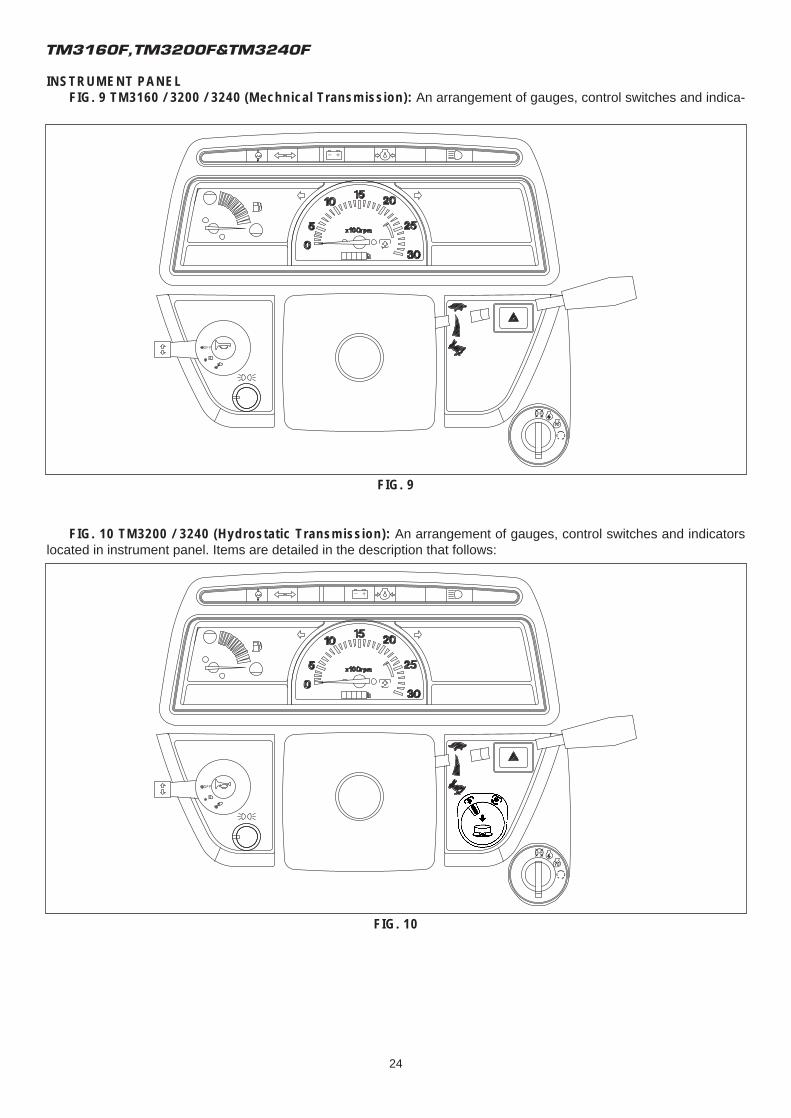
INSTRUMENT PANELFIG. 9 TM3160 / 3200 / 3240 (Mechnical Transmission): An arrangement of gauges, control switches and indica-
FIG. 9
FIG. 10 TM3200 / 3240 (Hydrostatic Transmission): An arrangement of gauges, control switches and indicatorslocated in instrument panel. Items are detailed in the description that follows:
FIG. 10
INSTRUMENTS & CONTROLS
25
Electrical Fuel Shut-Off
Turning the main switch to off will stop the engine.
• This tractor is equipped with a solenoid and a timer to shut the fuel off and the engine. When the main switch key is turned to off position, the timer activates the solenoid to shut the fuel off and hold it off for ten seconds, the solenoid then returns to "fuel on" position. The main switch key also overrides the timer to turn the fuel back on and allow the engine to be started immediately after being stopped.
Main Switch
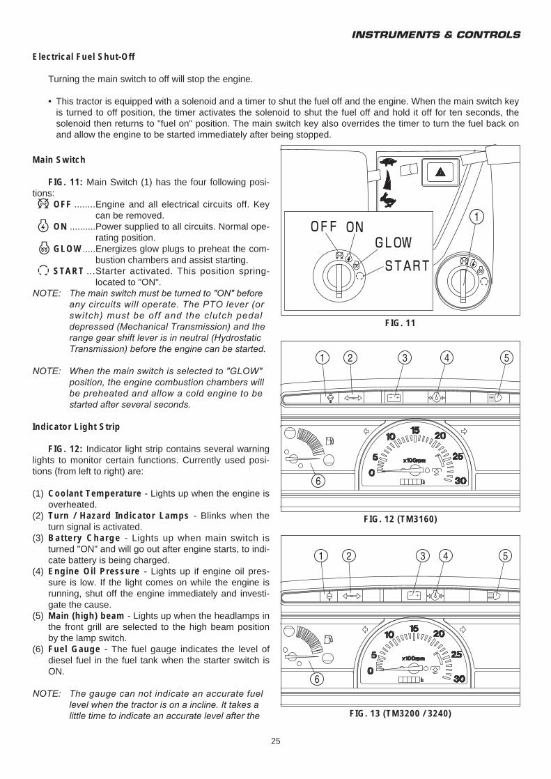
FIG. 11: Main Switch (1) has the four following posi-tions:p OFF ........Engine and all electrical circuits off. Key
can be removed.O ON ..........Power supplied to all circuits. Normal ope-
rating position.G GLOW.....Energizes glow plugs to preheat the com-
bustion chambers and assist starting.f START ...Starter activated. This position spring-
located to "ON".NOTE: The main switch must be turned to "ON" before
any circuits will operate. The PTO lever (or switch) must be off and the clutch pedal depressed (Mechanical Transmission) and the range gear shift lever is in neutral (Hydrostatic Transmission) before the engine can be started.
NOTE: When the main switch is selected to "GLOW" position, the engine combustion chambers will be preheated and allow a cold engine to be started after several seconds.
Indicator Light Strip
FIG. 12: Indicator light strip contains several warninglights to monitor certain functions. Currently used posi-tions (from left to right) are:
(1) Coolant Temperature - Lights up when the engine is overheated.
(2) Turn / Hazard Indicator Lamps - Blinks when the turn signal is activated.
(3) Battery Charge - Lights up when main switch is turned "ON" and will go out after engine starts, to indi-cate battery is being charged.
(4) Engine Oil Pressure - Lights up if engine oil pres-sure is low. If the light comes on while the engine is running, shut off the engine immediately and investi-gate the cause.
(5) Main (high) beam - Lights up when the headlamps in the front grill are selected to the high beam position by the lamp switch.
(6) Fuel Gauge - The fuel gauge indicates the level of diesel fuel in the fuel tank when the starter switch is ON.
NOTE: The gauge can not indicate an accurate fuel level when the tractor is on a incline. It takes a little time to indicate an accurate level after the
FIG. 11
FIG. 13 (TM3200 / 3240)
FIG. 12 (TM3160)
TM3160F,TM3200F&TM3240F
26
tractor recovers its horizontal position limit.
CAUTION: DO NOT service hot engine. Allowto completely cool before servicing or remov-ing radiator cap
NOTE: Use only clean diesel fuel and clean area to pre-vent dirt / water into fuel tank when refilling. DO NOT run out of fuel as bleeding air from the sys-tem will be required. Keep fuel tank full to mini-mize condensation.
CAUTION: DO NOT refill fuel tank with enginerunning or hot. Allow cooling period. DO NOTsmoke near fuel tank and clean up any spiltfuel.
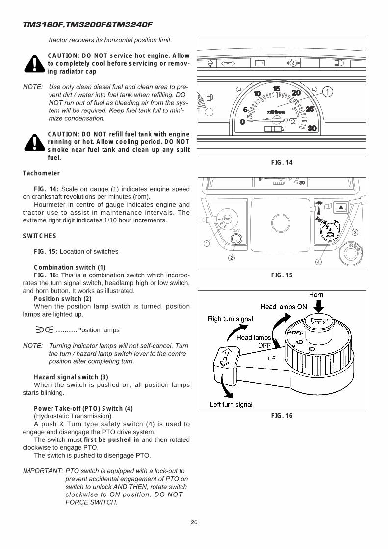
Tachometer
FIG. 14: Scale on gauge (1) indicates engine speedon crankshaft revolutions per minutes (rpm).
Hourmeter in centre of gauge indicates engine andtractor use to assist in maintenance intervals. Theextreme right digit indicates 1/10 hour increments.
SWITCHES
FIG. 15: Location of switches
Combination switch (1)FIG. 16: This is a combination switch which incorpo-
rates the turn signal switch, headlamp high or low switch,and horn button. It works as illustrated.
Position switch (2)When the position lamp switch is turned, position
lamps are lighted up.
............Position lamps
NOTE: Turning indicator lamps will not self-cancel. Turn the turn / hazard lamp switch lever to the centre position after completing turn.
Hazard signal switch (3)When the switch is pushed on, all position lamps
starts blinking.
Power Take-off (PTO) Switch (4)(Hydrostatic Transmission)A push & Turn type safety switch (4) is used to
engage and disengage the PTO drive system.The switch must first be pushed in and then rotated
clockwise to engage PTO.The switch is pushed to disengage PTO.
IMPORTANT: PTO switch is equipped with a lock-out to prevent accidental engagement of PTO on switch to unlock AND THEN, rotate switch clockwise to ON posit ion. DO NOT FORCE SWITCH.
FIG. 14
FIG. 15
FIG. 16
INSTRUMENTS & CONTROLS
27
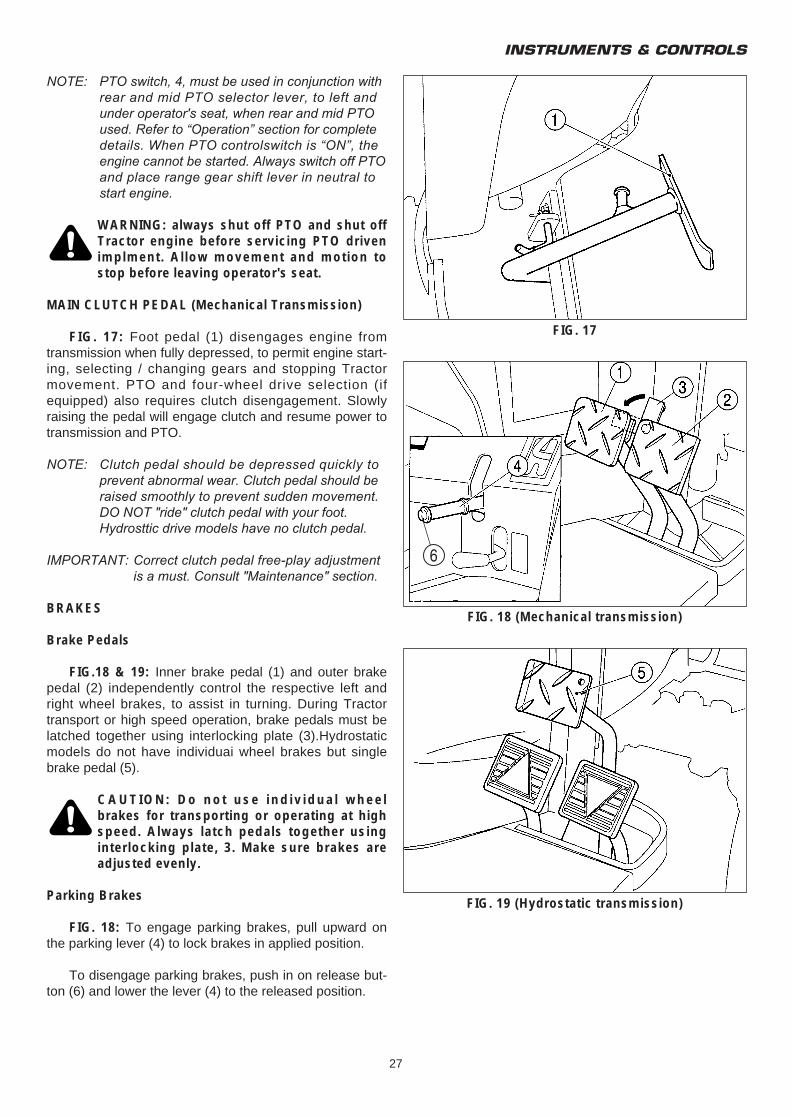
NOTE: PTO switch, 4, must be used in conjunction with rear and mid PTO selector lever, to left and under operator's seat, when rear and mid PTO used. Refer to “Operation” section for complete details. When PTO controlswitch is “ON”, the engine cannot be started. Always switch off PTO and place range gear shift lever in neutral to start engine.
WARNING: always shut off PTO and shut offTractor engine before servicing PTO drivenimplment. Allow movement and motion tostop before leaving operator's seat.
MAIN CLUTCH PEDAL (Mechanical Transmission)
FIG. 17: Foot pedal (1) disengages engine fromtransmission when fully depressed, to permit engine start-ing, selecting / changing gears and stopping Tractormovement. PTO and four-wheel drive selection (ifequipped) also requires clutch disengagement. Slowlyraising the pedal will engage clutch and resume power totransmission and PTO.
NOTE: Clutch pedal should be depressed quickly to prevent abnormal wear. Clutch pedal should be raised smoothly to prevent sudden movement. DO NOT "ride" clutch pedal with your foot.Hydrosttic drive models have no clutch pedal.
IMPORTANT: Correct clutch pedal free-play adjustment is a must. Consult "Maintenance" section.
BRAKES
Brake Pedals
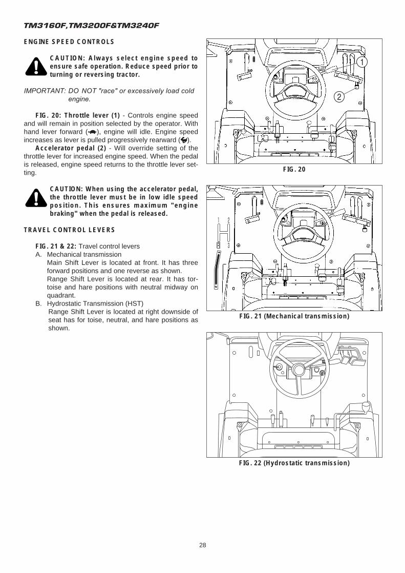
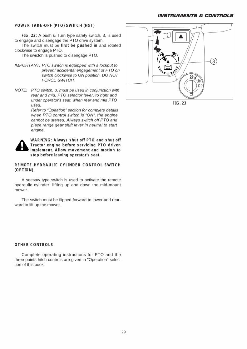
FIG.18 & 19: Inner brake pedal (1) and outer brakepedal (2) independently control the respective left andright wheel brakes, to assist in turning. During Tractortransport or high speed operation, brake pedals must belatched together using interlocking plate (3).Hydrostaticmodels do not have individuai wheel brakes but singlebrake pedal (5).
CAUTION: Do not use individual wheelbrakes for transporting or operating at highspeed. Always latch pedals together usinginterlocking plate, 3. Make sure brakes areadjusted evenly.
Parking Brakes
FIG. 18: To engage parking brakes, pull upward onthe parking lever (4) to lock brakes in applied position.
To disengage parking brakes, push in on release but-ton (6) and lower the lever (4) to the released position.
FIG. 17
FIG. 18 (Mechanical transmission)
FIG. 19 (Hydrostatic transmission)
TM3160F,TM3200F&TM3240F
28
ENGINE SPEED CONTROLS
CAUTION: Always select engine speed toensure safe operation. Reduce speed prior toturning or reversing tractor.
IMPORTANT: DO NOT "race" or excessively load cold engine.
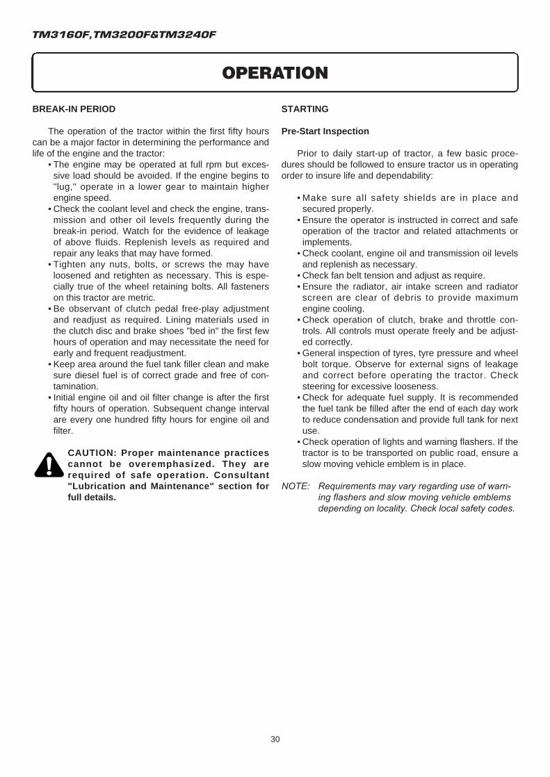
FIG. 20: Throttle lever (1) - Controls engine speedand will remain in position selected by the operator. Withhand lever forward (t), engine will idle. Engine speedincreases as lever is pulled progressively rearward (r).
Accelerator pedal (2) - Will override setting of thethrottle lever for increased engine speed. When the pedalis released, engine speed returns to the throttle lever set-ting.
CAUTION: When using the accelerator pedal,the throttle lever must be in low idle speedposition. This ensures maximum "enginebraking" when the pedal is released.
TRAVEL CONTROL LEVERS
FIG. 21 & 22: Travel control leversA. Mechanical transmission
Main Shift Lever is located at front. It has three forward positions and one reverse as shown.Range Shift Lever is located at rear. It has tor-toise and hare positions with neutral midway on quadrant.
B. Hydrostatic Transmission (HST)Range Shift Lever is located at right downside of seat has for toise, neutral, and hare positions as shown.
FIG. 20
FIG. 21 (Mechanical transmission)
FIG. 22 (Hydrostatic transmission)
INSTRUMENTS & CONTROLS
29
POWER TAKE-OFF (PTO) SWITCH (HST)
FIG. 22: A push & Turn type safety switch, 3, is usedto engage and disengage the PTO drive system.
The switch must be first be pushed in and rotatedclockwise to engage PTO.
The swictch is pushed to disengage PTO.
IMPORTANT: PTO sw itch is equipped with a lockput to prevent accidental engagement of PTO on switch clockwise to ON position. DO NOT FORCE SWITCH.
NOTE: PTO switch, 3, must be used in conjunction with rear and mid. PTO selector lever, to right and under operator's seat, when rear and mid PTO used.Refer to “Opeation” section for complete details when PTO control switch is “ON”, the engine cannot be started. Always switch off PTO and place range gear shift lever in neutral to start engine.
WARNING: Always shut off PTO and shut offTractor engine before servicing PTO drivenimplement. Allow movement and motion tostop before leaving operator's seat.
REMOTE HYDRAULIC CYLINDER CONTROL SWITCH(OPTION)
A seesaw type switch is used to activate the remotehydraulic cylinder: lifting up and down the mid-mountmower.
The switch must be flipped forward to lower and rear-ward to lift up the mower.
OTHER CONTROLS
Complete operating instructions for PTO and thethree-points hitch controls are given in "Operation" selec-tion of this book.
FIG. 23
3
TM3160F,TM3200F&TM3240F
30
BREAK-IN PERIOD
The operation of the tractor within the first fifty hourscan be a major factor in determining the performance andlife of the engine and the tractor:
• The engine may be operated at full rpm but exces-sive load should be avoided. If the engine begins to "lug," operate in a lower gear to maintain higher engine speed.
• Check the coolant level and check the engine, trans-mission and other oil levels frequently during the break-in period. Watch for the evidence of leakage of above fluids. Replenish levels as required and repair any leaks that may have formed.
• Tighten any nuts, bolts, or screws the may have loosened and retighten as necessary. This is espe-cially true of the wheel retaining bolts. All fasteners on this tractor are metric.
• Be observant of clutch pedal free-play adjustment and readjust as required. Lining materials used in the clutch disc and brake shoes "bed in" the first few hours of operation and may necessitate the need for early and frequent readjustment.
• Keep area around the fuel tank filler clean and make sure diesel fuel is of correct grade and free of con-tamination.
• Initial engine oil and oil filter change is after the first fifty hours of operation. Subsequent change interval are every one hundred fifty hours for engine oil and filter.
CAUTION: Proper maintenance practicescannot be overemphasized. They arerequired of safe operation. Consultant"Lubrication and Maintenance" section forfull details.
STARTING
Pre-Start Inspection
Prior to daily start-up of tractor, a few basic proce-dures should be followed to ensure tractor us in operatingorder to insure life and dependability:
• Make sure all safety shields are in place and secured properly.
• Ensure the operator is instructed in correct and safe operation of the tractor and related attachments or implements.
• Check coolant, engine oil and transmission oil levels and replenish as necessary.
• Check fan belt tension and adjust as require.• Ensure the radiator, air intake screen and radiator
screen are clear of debris to provide maximum engine cooling.
• Check operation of clutch, brake and throttle con-trols. All controls must operate freely and be adjust-ed correctly.
• General inspection of tyres, tyre pressure and wheel bolt torque. Observe for external signs of leakage and correct before operating the tractor. Check steering for excessive looseness.
• Check for adequate fuel supply. It is recommended the fuel tank be filled after the end of each day work to reduce condensation and provide full tank for next use.
• Check operation of lights and warning flashers. If the tractor is to be transported on public road, ensure a slow moving vehicle emblem is in place.
NOTE: Requirements may vary regarding use of warn-ing flashers and slow moving vehicle emblems depending on locality. Check local safety codes.
OPERATION
OPERATION
31
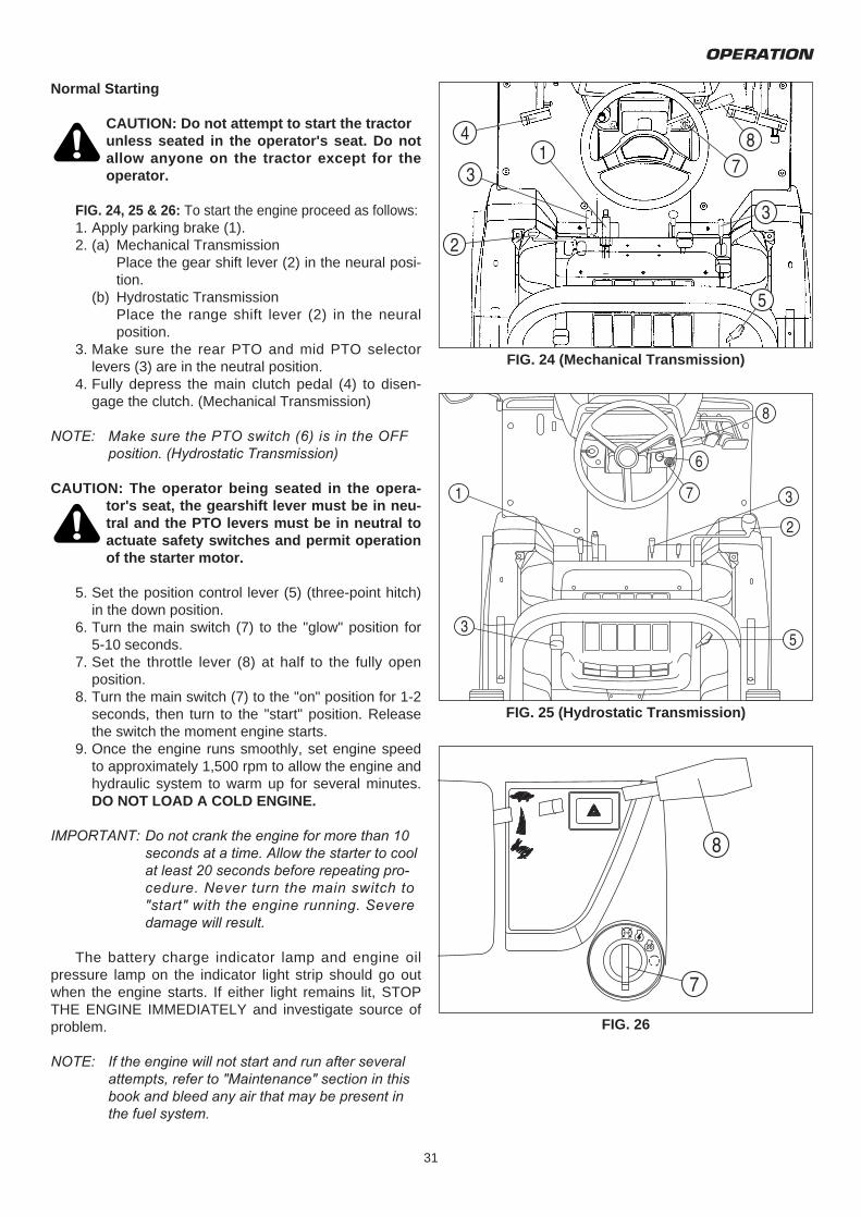
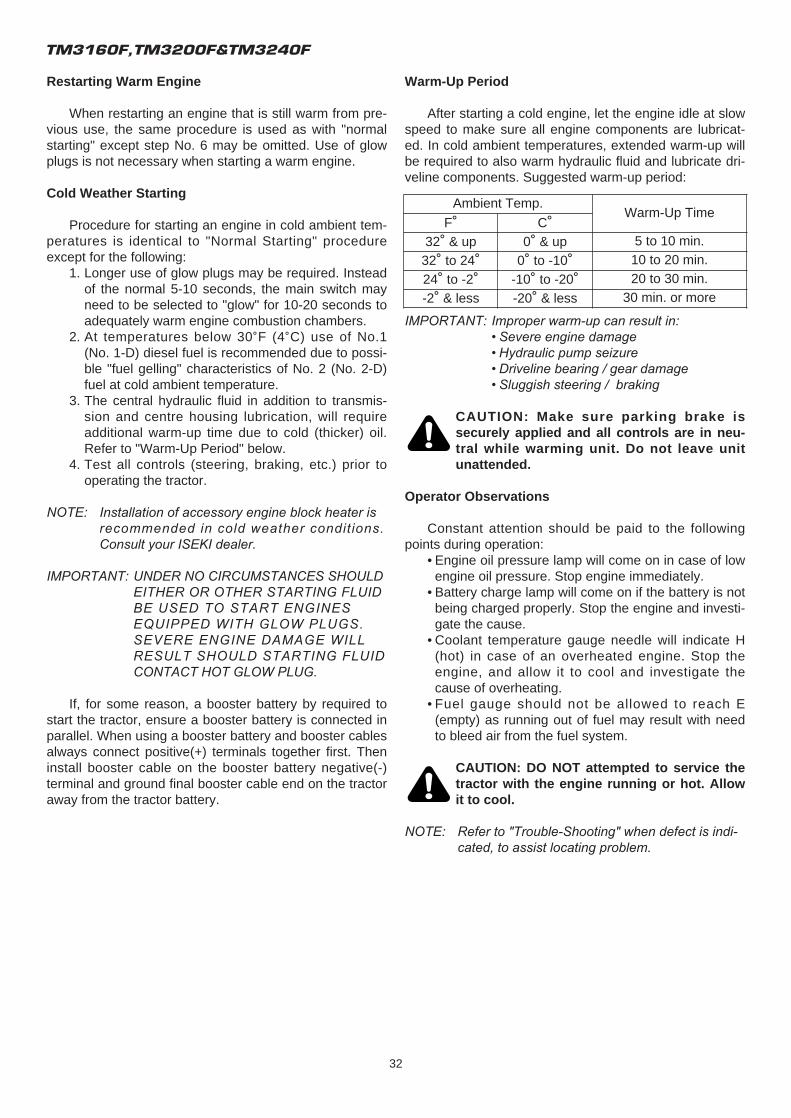
Normal Starting
CAUTION: Do not attempt to start the tractor unless seated in the operator's seat. Do notallow anyone on the tractor except for theoperator.
FIG. 24, 25 & 26: To start the engine proceed as follows:1. Apply parking brake (1).2. (a) Mechanical Transmission
Place the gear shift lever (2) in the neural posi-tion.
(b) Hydrostatic TransmissionPlace the range shift lever (2) in the neural position.
3. Make sure the rear PTO and mid PTO selector levers (3) are in the neutral position.
4. Fully depress the main clutch pedal (4) to disen-gage the clutch. (Mechanical Transmission)
NOTE: Make sure the PTO switch (6) is in the OFF position. (Hydrostatic Transmission)
CAUTION: The operator being seated in the opera-tor's seat, the gearshift lever must be in neu-tral and the PTO levers must be in neutral toactuate safety switches and permit operationof the starter motor.
5. Set the position control lever (5) (three-point hitch) in the down position.
6. Turn the main switch (7) to the "glow" position for 5-10 seconds.
7. Set the throttle lever (8) at half to the fully open position.
8. Turn the main switch (7) to the "on" position for 1-2 seconds, then turn to the "start" position. Release the switch the moment engine starts.
9. Once the engine runs smoothly, set engine speed to approximately 1,500 rpm to allow the engine and hydraulic system to warm up for several minutes. DO NOT LOAD A COLD ENGINE.
IMPORTANT: Do not crank the engine for more than 10 seconds at a time. Allow the starter to cool at least 20 seconds before repeating pro-cedure. Never turn the main switch to "start" with the engine running. Severe damage will result.
The battery charge indicator lamp and engine oilpressure lamp on the indicator light strip should go outwhen the engine starts. If either light remains lit, STOPTHE ENGINE IMMEDIATELY and investigate source ofproblem.
NOTE: If the engine will not start and run after several attempts, refer to "Maintenance" section in this book and bleed any air that may be present in the fuel system.
FIG. 24 (Mechanical Transmission)
FIG. 25 (Hydrostatic Transmission)
FIG. 26
TM3160F,TM3200F&TM3240F
32
Restarting Warm Engine
When restarting an engine that is still warm from pre-vious use, the same procedure is used as with "normalstarting" except step No. 6 may be omitted. Use of glowplugs is not necessary when starting a warm engine.
Cold Weather Starting
Procedure for starting an engine in cold ambient tem-peratures is identical to "Normal Starting" procedureexcept for the following:
1. Longer use of glow plugs may be required. Instead of the normal 5-10 seconds, the main switch may need to be selected to "glow" for 10-20 seconds to adequately warm engine combustion chambers.
2. At temperatures below 30˚F (4˚C) use of No.1 (No. 1-D) diesel fuel is recommended due to possi-ble "fuel gelling" characteristics of No. 2 (No. 2-D) fuel at cold ambient temperature.
3. The central hydraulic fluid in addition to transmis-sion and centre housing lubrication, will require additional warm-up time due to cold (thicker) oil. Refer to "Warm-Up Period" below.
4. Test all controls (steering, braking, etc.) prior to operating the tractor.
NOTE: Installation of accessory engine block heater is recommended in cold weather conditions. Consult your ISEKI dealer.
IMPORTANT: UNDER NO CIRCUMSTANCES SHOULD EITHER OR OTHER STARTING FLUID BE USED TO START ENGINES EQUIPPED WITH GLOW PLUGS. SEVERE ENGINE DAMAGE WILL RESULT SHOULD STARTING FLUID CONTACT HOT GLOW PLUG.
If, for some reason, a booster battery by required tostart the tractor, ensure a booster battery is connected inparallel. When using a booster battery and booster cablesalways connect positive(+) terminals together first. Theninstall booster cable on the booster battery negative(-)terminal and ground final booster cable end on the tractoraway from the tractor battery.
Warm-Up Period
After starting a cold engine, let the engine idle at slowspeed to make sure all engine components are lubricat-ed. In cold ambient temperatures, extended warm-up willbe required to also warm hydraulic fluid and lubricate dri-veline components. Suggested warm-up period:
IMPORTANT: Improper warm-up can result in:• Severe engine damage• Hydraulic pump seizure• Driveline bearing / gear damage• Sluggish steering / braking
CAUTION: Make sure parking brake issecurely applied and all controls are in neu-tral while warming unit. Do not leave unitunattended.
Operator Observations
Constant attention should be paid to the followingpoints during operation:
• Engine oil pressure lamp will come on in case of low engine oil pressure. Stop engine immediately.
• Battery charge lamp will come on if the battery is not being charged properly. Stop the engine and investi-gate the cause.
• Coolant temperature gauge needle will indicate H (hot) in case of an overheated engine. Stop the engine, and allow it to cool and investigate the cause of overheating.
• Fuel gauge should not be allowed to reach E (empty) as running out of fuel may result with need to bleed air from the fuel system.
CAUTION: DO NOT attempted to service thetractor with the engine running or hot. Allowit to cool.
NOTE: Refer to "Trouble-Shooting" when defect is indi-cated, to assist locating problem.
Ambient Temp.Warm-Up Time
F˚ C˚32˚ & up 0˚ & up 5 to 10 min.
32˚ to 24˚ 0˚ to -10˚ 10 to 20 min.
24˚ to -2˚ -10˚ to -20˚ 20 to 30 min.
-2˚ & less -20˚ & less 30 min. or more
OPERATION
33
MECHANICAL TRANSMISSION
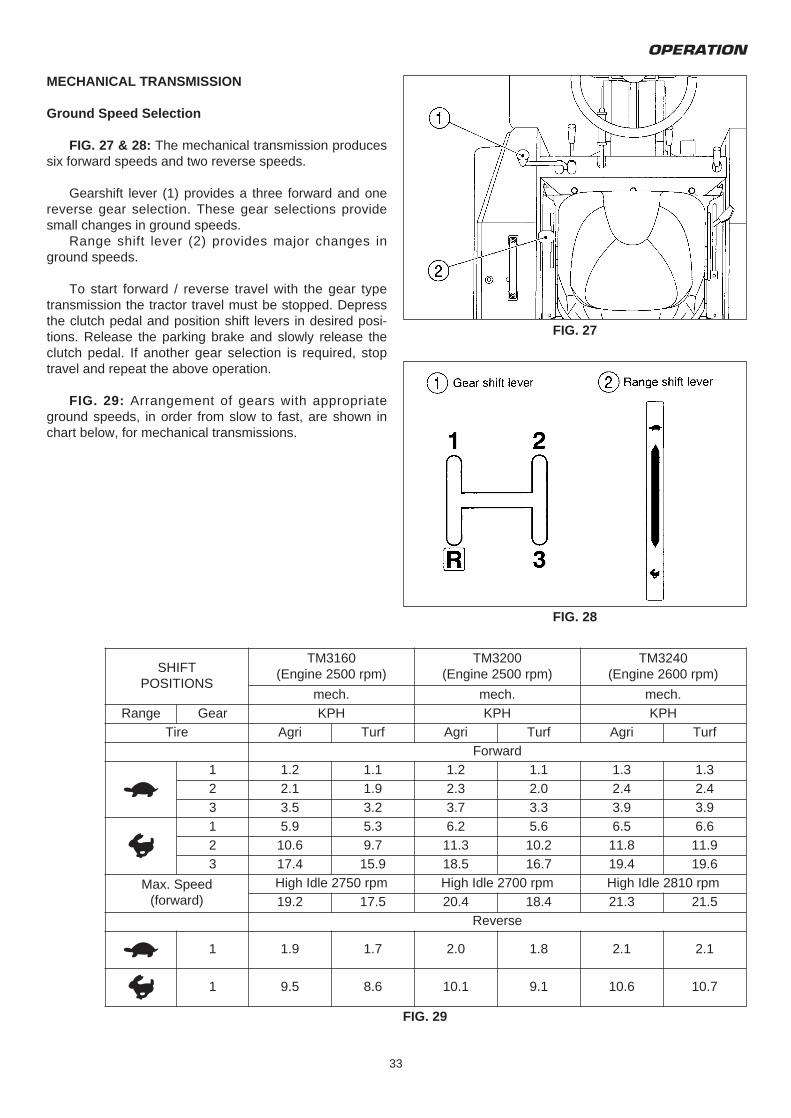
Ground Speed Selection
FIG. 27 & 28: The mechanical transmission producessix forward speeds and two reverse speeds.
Gearshift lever (1) provides a three forward and onereverse gear selection. These gear selections providesmall changes in ground speeds.
Range shift lever (2) provides major changes inground speeds.
To start forward / reverse travel with the gear typetransmission the tractor travel must be stopped. Depressthe clutch pedal and position shift levers in desired posi-tions. Release the parking brake and slowly release theclutch pedal. If another gear selection is required, stoptravel and repeat the above operation.
FIG. 29: Arrangement of gears with appropriateground speeds, in order from slow to fast, are shown inchart below, for mechanical transmissions.
FIG. 27
FIG. 28
SHIFTPOSITIONS
TM3160(Engine 2500 rpm)
TM3200(Engine 2500 rpm)
TM3240(Engine 2600 rpm)
mech. mech. mech.Range Gear KPH KPH KPH
Tire Agri Turf Agri Turf Agri TurfForward
t1 1.2 1.1 1.2 1.1 1.3 1.32 2.1 1.9 2.3 2.0 2.4 2.43 3.5 3.2 3.7 3.3 3.9 3.9
r1 5.9 5.3 6.2 5.6 6.5 6.62 10.6 9.7 11.3 10.2 11.8 11.93 17.4 15.9 18.5 16.7 19.4 19.6
Max. Speed(forward)
High Idle 2750 rpm High Idle 2700 rpm High Idle 2810 rpm19.2 17.5 20.4 18.4 21.3 21.5
Reverse
t 1 1.9 1.7 2.0 1.8 2.1 2.1
r 1 9.5 8.6 10.1 9.1 10.6 10.7
FIG. 29
TM3160F,TM3200F&TM3240F
34
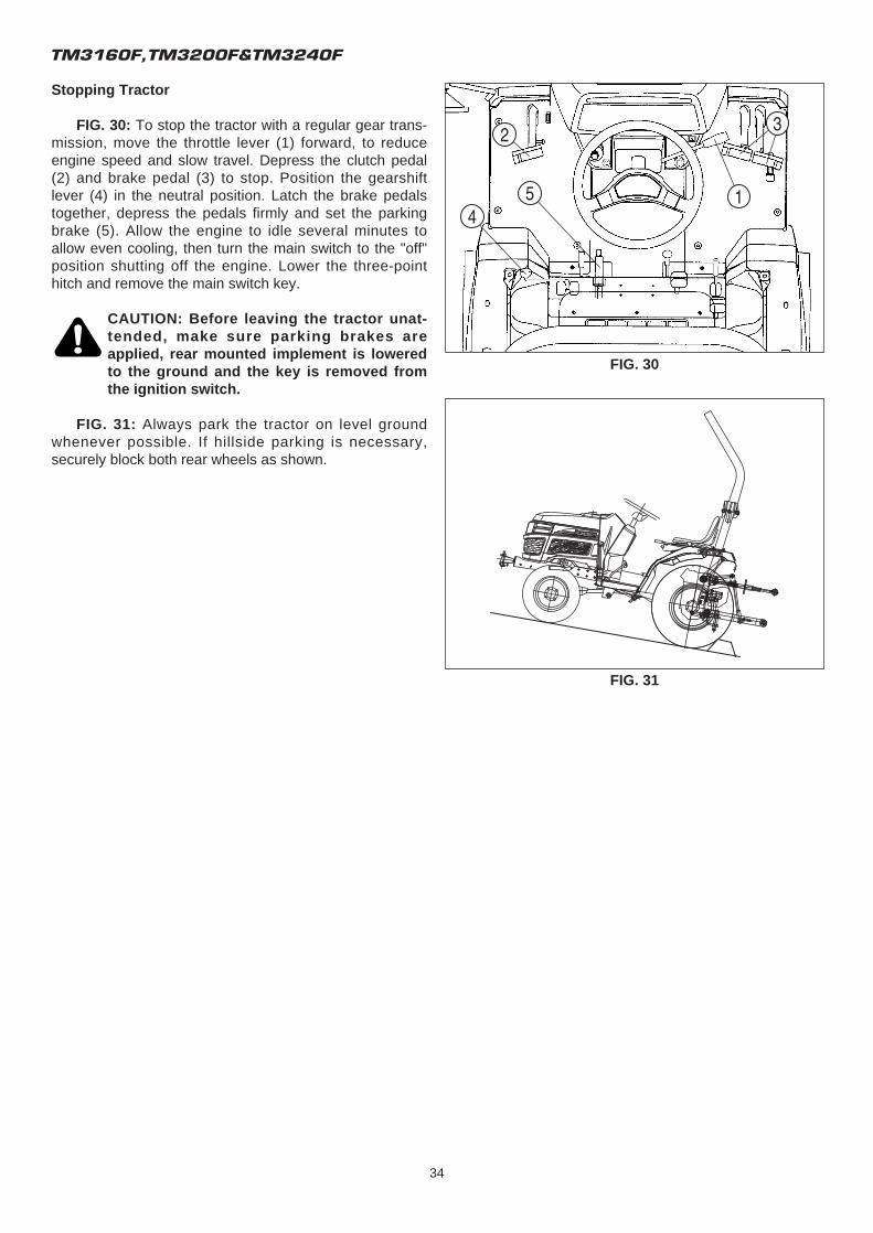
Stopping Tractor
FIG. 30: To stop the tractor with a regular gear trans-mission, move the throttle lever (1) forward, to reduceengine speed and slow travel. Depress the clutch pedal(2) and brake pedal (3) to stop. Position the gearshiftlever (4) in the neutral position. Latch the brake pedalstogether, depress the pedals firmly and set the parkingbrake (5). Allow the engine to idle several minutes toallow even cooling, then turn the main switch to the "off"position shutting off the engine. Lower the three-pointhitch and remove the main switch key.
CAUTION: Before leaving the tractor unat-tended, make sure parking brakes areapplied, rear mounted implement is loweredto the ground and the key is removed fromthe ignition switch.
FIG. 31: Always park the tractor on level groundwhenever possible. If hillside parking is necessary,securely block both rear wheels as shown.
FIG. 30
FIG. 31
OPERATION
35
HYDROSTATIC TRANSMISSION
Ground Speed Selection
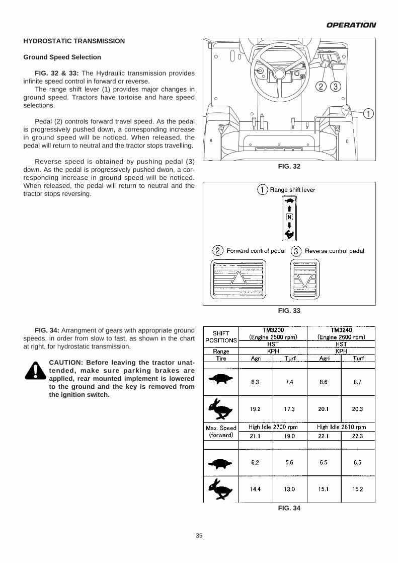
FIG. 32 & 33: The Hydraulic transmission providesinfinite speed control in forward or reverse.
The range shift lever (1) provides major changes inground speed. Tractors have tortoise and hare speedselections.
Pedal (2) controls forward travel speed. As the pedalis progressively pushed down, a corresponding increasein ground speed will be noticed. When released, thepedal will return to neutral and the tractor stops travelling.
Reverse speed is obtained by pushing pedal (3)down. As the pedal is progressively pushed dwon, a cor-responding increase in ground speed will be noticed.When released, the pedal will return to neutral and thetractor stops reversing.
FIG. 34: Arrangment of gears with appropriate groundspeeds, in order from slow to fast, as shown in the chartat right, for hydrostatic transmission.
CAUTION: Before leaving the tractor unat-tended, make sure parking brakes areapplied, rear mounted implement is loweredto the ground and the key is removed fromthe ignition switch.
FIG. 32
FIG. 33
FIG. 34
TM3160F,TM3200F&TM3240F
36
Stopping Tractor
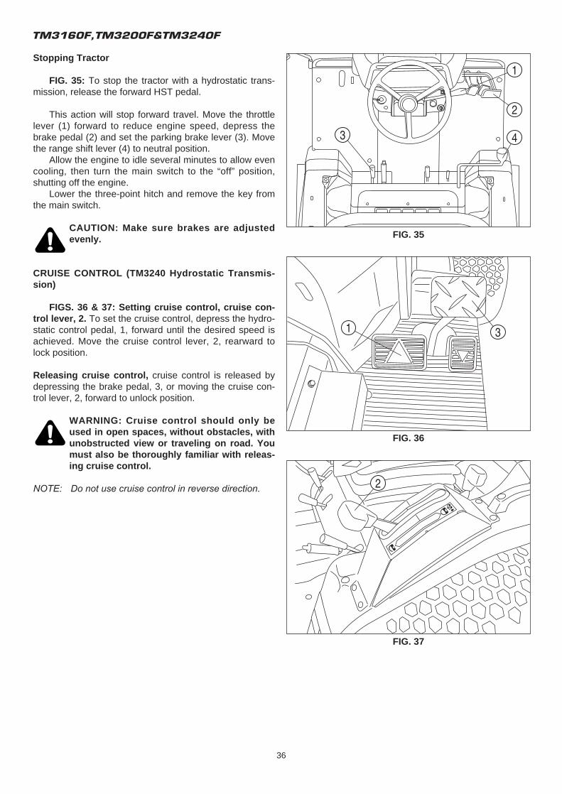
FIG. 35: To stop the tractor with a hydrostatic trans-mission, release the forward HST pedal.
This action will stop forward travel. Move the throttlelever (1) forward to reduce engine speed, depress thebrake pedal (2) and set the parking brake lever (3). Movethe range shift lever (4) to neutral position.
Allow the engine to idle several minutes to allow evencooling, then turn the main switch to the “off” position,shutting off the engine.
Lower the three-point hitch and remove the key fromthe main switch.
CAUTION: Make sure brakes are adjustedevenly.
CRUISE CONTROL (TM3240 Hydrostatic Transmis-sion)
FIGS. 36 & 37: Setting cruise control, cruise con-trol lever, 2. To set the cruise control, depress the hydro-static control pedal, 1, forward until the desired speed isachieved. Move the cruise control lever, 2, rearward tolock position.
Releasing cruise control, cruise control is released bydepressing the brake pedal, 3, or moving the cruise con-trol lever, 2, forward to unlock position.
WARNING: Cruise control should only beused in open spaces, without obstacles, withunobstructed view or traveling on road. Youmust also be thoroughly familiar with releas-ing cruise control.
NOTE: Do not use cruise control in reverse direction.
FIG. 35
FIG. 36
FIG. 37
OPERATION
37
DIFFERENTIAL LOCK OPERATION
Mechanical Transmission
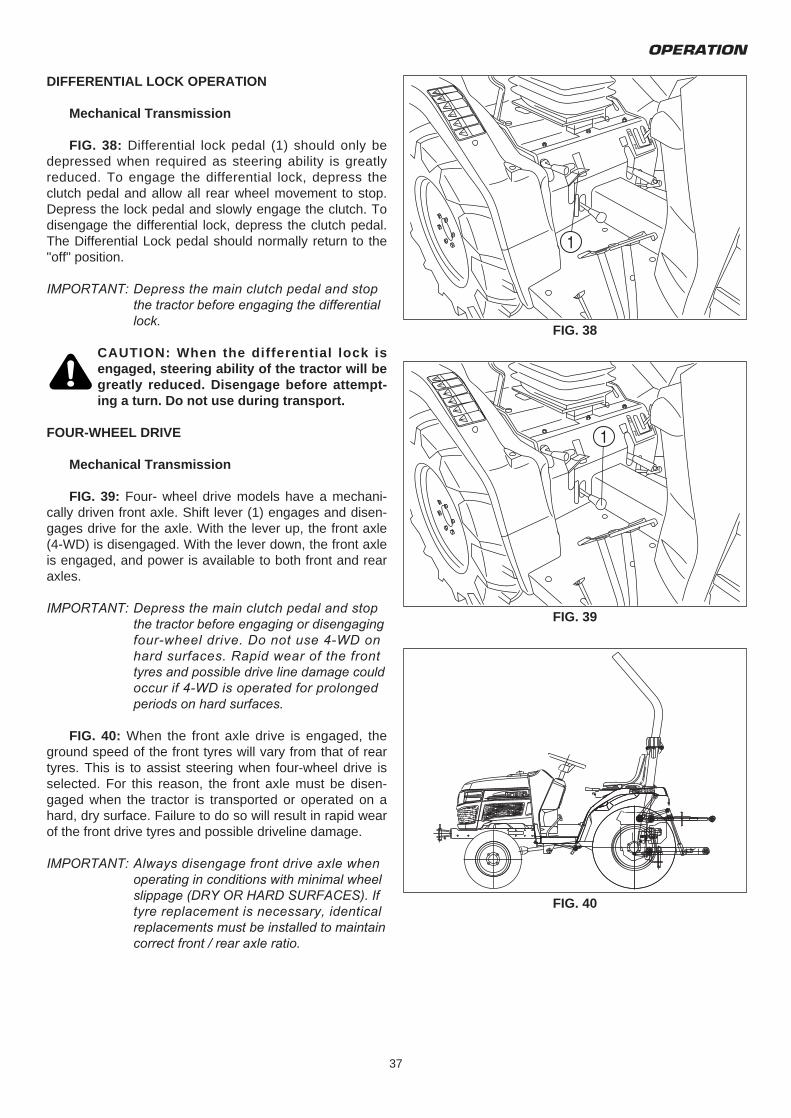
FIG. 38: Differential lock pedal (1) should only bedepressed when required as steering ability is greatlyreduced. To engage the differential lock, depress theclutch pedal and allow all rear wheel movement to stop.Depress the lock pedal and slowly engage the clutch. Todisengage the differential lock, depress the clutch pedal.The Differential Lock pedal should normally return to the"off" position.
IMPORTANT: Depress the main clutch pedal and stop the tractor before engaging the differential lock.
CAUTION: When the differential lock isengaged, steering ability of the tractor will begreatly reduced. Disengage before attempt-ing a turn. Do not use during transport.
FOUR-WHEEL DRIVE
Mechanical Transmission
FIG. 39: Four- wheel drive models have a mechani-cally driven front axle. Shift lever (1) engages and disen-gages drive for the axle. With the lever up, the front axle(4-WD) is disengaged. With the lever down, the front axleis engaged, and power is available to both front and rearaxles.
IMPORTANT: Depress the main clutch pedal and stop the tractor before engaging or disengaging four-wheel drive. Do not use 4-WD on hard surfaces. Rapid wear of the front tyres and possible drive line damage could occur if 4-WD is operated for prolonged periods on hard surfaces.
FIG. 40: When the front axle drive is engaged, theground speed of the front tyres will vary from that of reartyres. This is to assist steering when four-wheel drive isselected. For this reason, the front axle must be disen-gaged when the tractor is transported or operated on ahard, dry surface. Failure to do so will result in rapid wearof the front drive tyres and possible driveline damage.
IMPORTANT: Always disengage front drive axle when operating in conditions with minimal wheel slippage (DRY OR HARD SURFACES). If tyre replacement is necessary, identical replacements must be installed to maintain correct front / rear axle ratio.
FIG. 38
FIG. 40
FIG. 39
TM3160F,TM3200F&TM3240F
38
DIFFERENTIAL LOCK OPERATION
Hydrostatic Transmission
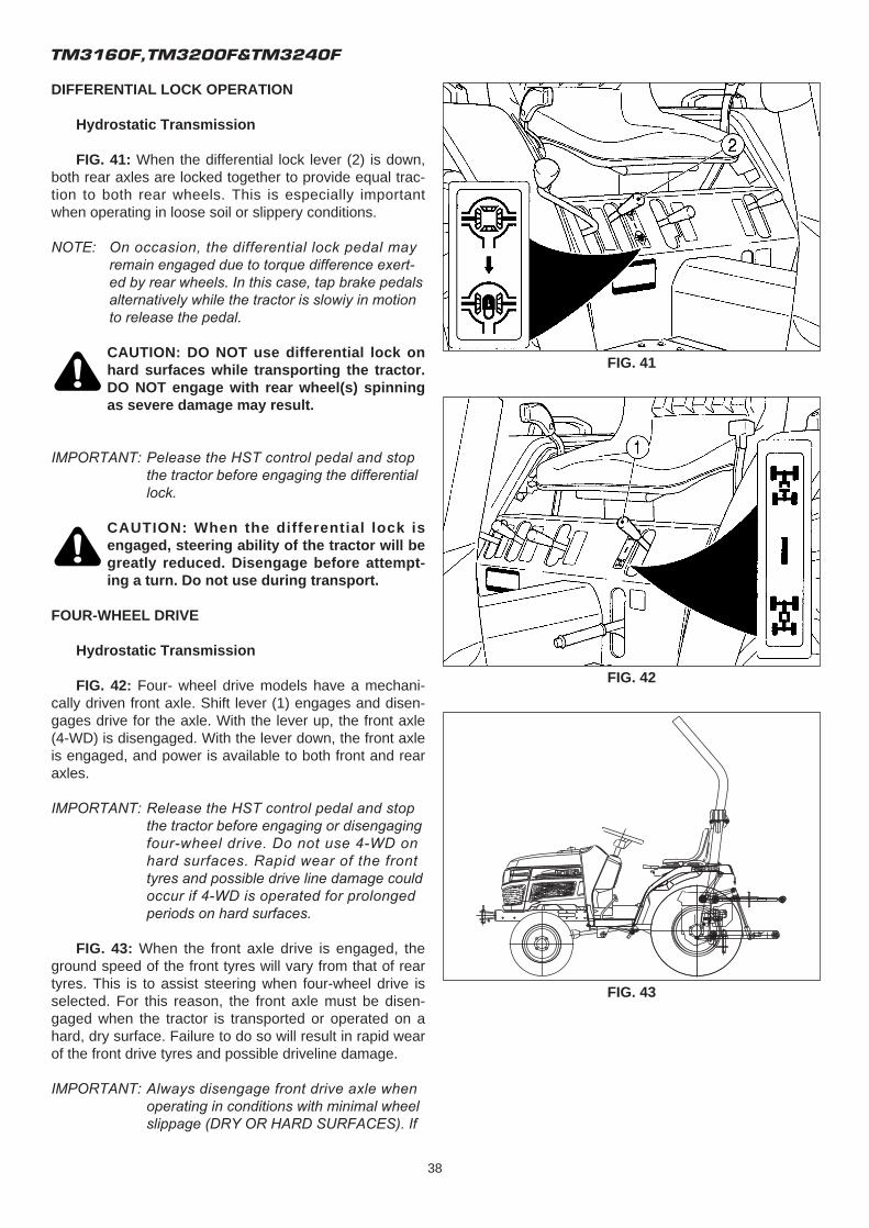
FIG. 41: When the differential lock lever (2) is down,both rear axles are locked together to provide equal trac-tion to both rear wheels. This is especially importantwhen operating in loose soil or slippery conditions.
NOTE: On occasion, the differential lock pedal may remain engaged due to torque difference exert-ed by rear wheels. In this case, tap brake pedals alternatively while the tractor is slowiy in motion to release the pedal.
CAUTION: DO NOT use differential lock onhard surfaces while transporting the tractor.DO NOT engage with rear wheel(s) spinningas severe damage may result.
IMPORTANT: Pelease the HST control pedal and stop the tractor before engaging the differential lock.
CAUTION: When the differential lock isengaged, steering ability of the tractor will begreatly reduced. Disengage before attempt-ing a turn. Do not use during transport.
FOUR-WHEEL DRIVE
Hydrostatic Transmission
FIG. 42: Four- wheel drive models have a mechani-cally driven front axle. Shift lever (1) engages and disen-gages drive for the axle. With the lever up, the front axle(4-WD) is disengaged. With the lever down, the front axleis engaged, and power is available to both front and rearaxles.
IMPORTANT: Release the HST control pedal and stop the tractor before engaging or disengaging four-wheel drive. Do not use 4-WD on hard surfaces. Rapid wear of the front tyres and possible drive line damage could occur if 4-WD is operated for prolonged periods on hard surfaces.
FIG. 43: When the front axle drive is engaged, theground speed of the front tyres will vary from that of reartyres. This is to assist steering when four-wheel drive isselected. For this reason, the front axle must be disen-gaged when the tractor is transported or operated on ahard, dry surface. Failure to do so will result in rapid wearof the front drive tyres and possible driveline damage.
IMPORTANT: Always disengage front drive axle when operating in conditions with minimal wheel slippage (DRY OR HARD SURFACES). If
FIG. 41
FIG. 43
FIG. 42
OPERATION
39
tyre replacement is necessary, identical replacements must be installed to maintain correct front / rear axle ratio.
POWER TAKE-OFF (PTO)
CAUTION: Disengage the rear PTO selectorlever, and shut off the engine prior to con-necting equipment to or disconnecting itfrom the tractor's PTO shaft. Make certain thedriver-shaft is securely locked in the annulargroove of the tractor PTO shaft before start-ing the tractor engine.
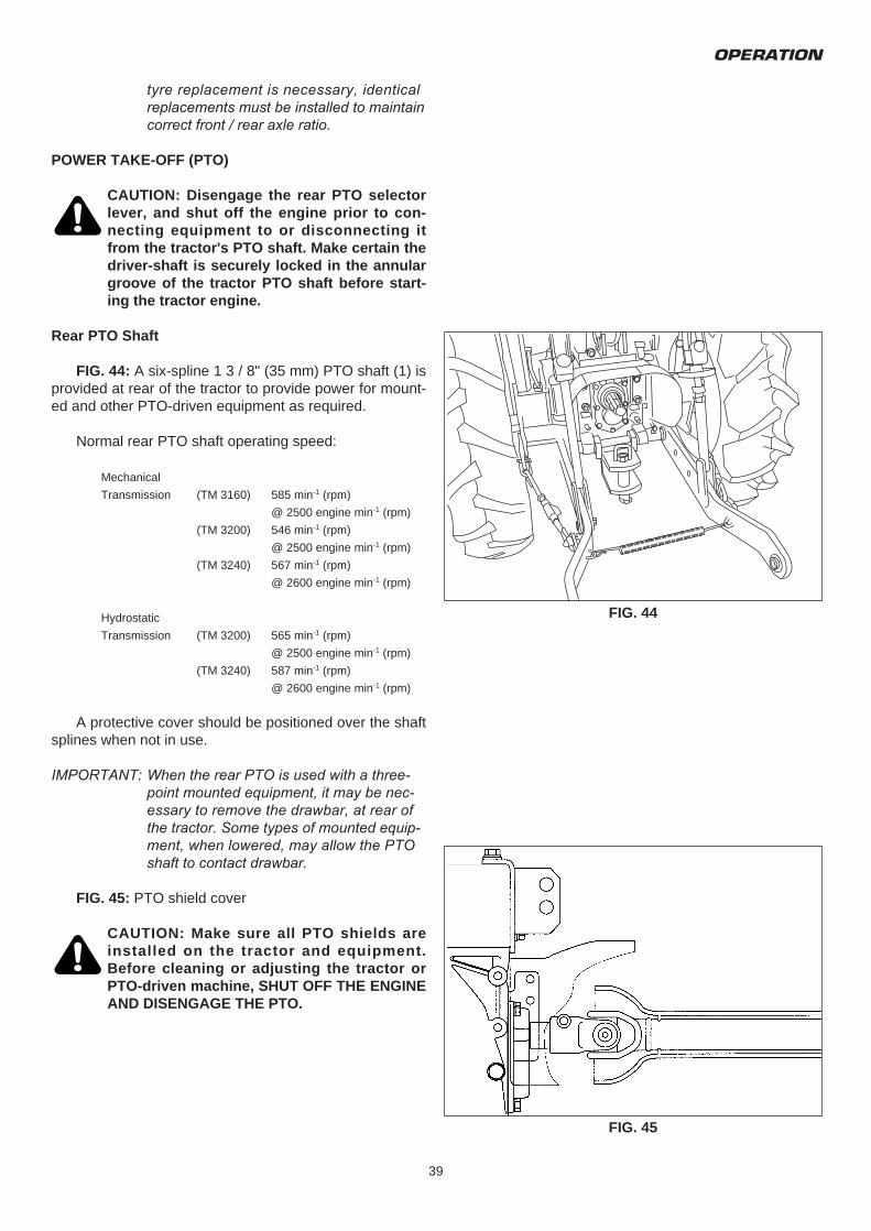
Rear PTO Shaft
FIG. 44: A six-spline 1 3 / 8" (35 mm) PTO shaft (1) isprovided at rear of the tractor to provide power for mount-ed and other PTO-driven equipment as required.
Normal rear PTO shaft operating speed:
Mechanical
Transmission (TM 3160) 585 min-1 (rpm)
@ 2500 engine min-1 (rpm)
(TM 3200) 546 min-1 (rpm)
@ 2500 engine min-1 (rpm)
(TM 3240) 567 min-1 (rpm)
@ 2600 engine min-1 (rpm)
Hydrostatic
Transmission (TM 3200) 565 min-1 (rpm)
@ 2500 engine min-1 (rpm)
(TM 3240) 587 min-1 (rpm)
@ 2600 engine min-1 (rpm)
A protective cover should be positioned over the shaftsplines when not in use.
IMPORTANT: When the rear PTO is used with a three-point mounted equipment, it may be nec-essary to remove the drawbar, at rear of the tractor. Some types of mounted equip-ment, when lowered, may allow the PTO shaft to contact drawbar.
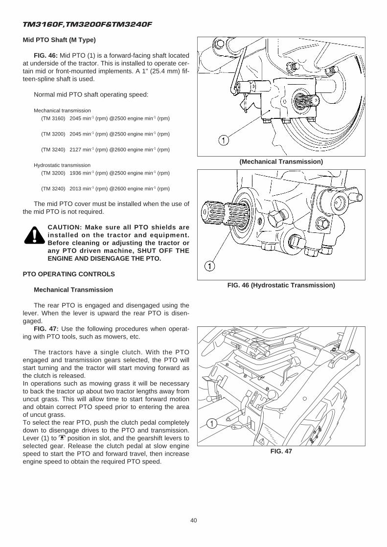
FIG. 45: PTO shield cover
CAUTION: Make sure all PTO shields areinstalled on the tractor and equipment.Before cleaning or adjusting the tractor orPTO-driven machine, SHUT OFF THE ENGINEAND DISENGAGE THE PTO.
FIG. 44
FIG. 45
TM3160F,TM3200F&TM3240F
40
Mid PTO Shaft (M Type)
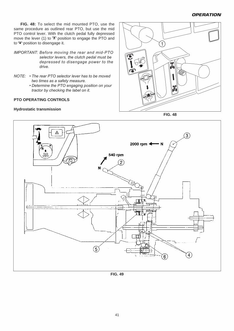
FIG. 46: Mid PTO (1) is a forward-facing shaft locatedat underside of the tractor. This is installed to operate cer-tain mid or front-mounted implements. A 1" (25.4 mm) fif-teen-spline shaft is used.
Normal mid PTO shaft operating speed:
Mechanical transmission
(TM 3160) 2045 min-1 (rpm) @2500 engine min-1 (rpm)
(TM 3200) 2045 min-1 (rpm) @2500 engine min-1 (rpm)
(TM 3240) 2127 min-1 (rpm) @2600 engine min-1 (rpm)
Hydrostatic transmission
(TM 3200) 1936 min-1 (rpm) @2500 engine min-1 (rpm)
(TM 3240) 2013 min-1 (rpm) @2600 engine min-1 (rpm)
The mid PTO cover must be installed when the use ofthe mid PTO is not required.
CAUTION: Make sure all PTO shields areinstalled on the tractor and equipment.Before cleaning or adjusting the tractor orany PTO driven machine, SHUT OFF THEENGINE AND DISENGAGE THE PTO.
PTO OPERATING CONTROLS
Mechanical Transmission
The rear PTO is engaged and disengaged using thelever. When the lever is upward the rear PTO is disen-gaged.
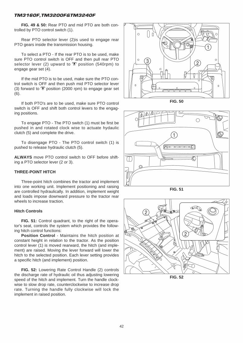
FIG. 47: Use the following procedures when operat-ing with PTO tools, such as mowers, etc.
The tractors have a single clutch. With the PTOengaged and transmission gears selected, the PTO willstart turning and the tractor will start moving forward asthe clutch is released.In operations such as mowing grass it will be necessaryto back the tractor up about two tractor lengths away fromuncut grass. This will allow time to start forward motionand obtain correct PTO speed prior to entering the areaof uncut grass.To select the rear PTO, push the clutch pedal completelydown to disengage drives to the PTO and transmission.Lever (1) to M position in slot, and the gearshift levers toselected gear. Release the clutch pedal at slow enginespeed to start the PTO and forward travel, then increaseengine speed to obtain the required PTO speed.
FIG. 46 (Hydrostatic Transmission)
FIG. 47
(Mechanical Transmission)
OPERATION
41
FIG. 48: To select the mid mounted PTO, use thesame procedure as outlined rear PTO, but use the midPTO control lever. With the clutch pedal fully depressedmove the lever (1) to M position to engage the PTO andto N position to disengage it.
IMPORTANT: Before moving the rear and mid-PTO selector levers, the clutch pedal must be depressed to disengage power to the drive.
NOTE: • The rear PTO selector lever has to be moved two times as a safety measure.
• Determine the PTO engaging position on your tractor by checking the label on it.
PTO OPERATING CONTROLS
Hydrostatic transmissionFIG. 48
FIG. 49
TM3160F,TM3200F&TM3240F
42
FIG. 49 & 50: Rear PTO and mid PTO are both con-trolled by PTO control switch (1).
Rear PTO selector lever (2)is used to engage rearPTO gears inside the transmission housing.
To select a PTO - If the rear PTO is to be used, makesure PTO control switch is OFF and then pull rear PTOselector lever (2) upward to M position (540rpm) toengage gear set (4).
If the mid PTO is to be used, make sure the PTO con-trol switch is OFF and then push mid PTO selector lever(3) forward to M position (2000 rpm) to engage gear set(6).
If both PTO's are to be used, make sure PTO controlswitch is OFF and shift both control levers to the engag-ing positions.
To engage PTO - The PTO switch (1) must be first bepushed in and rotated clock wise to actuate hydaulicclutch (5) and complete the drive.
To disengage PTO - The PTO control switch (1) ispushed to release hydraulic clutch (5).
ALWAYS move PTO control switch to OFF before shift-ing a PTO selector lever (2 or 3).
THREE-POINT HITCH
Three-point hitch combines the tractor and implementinto one working unit. Implement positioning and raisingare controlled hydraulically. In addition, implement weightand loads impose downward pressure to the tractor rearwheels to increase traction.
Hitch Controls
FIG. 51: Control quadrant, to the right of the opera-tor's seat, controls the system which provides the follow-ing hitch control functions:
Position Control - Maintains the hitch position atconstant height in relation to the tractor. As the positioncontrol lever (1) is moved rearward, the hitch (and imple-ment) are raised. Moving the lever forward will lower thehitch to the selected position. Each lever setting providesa specific hitch (and implement) position.
FIG. 52: Lowering Rate Control Handle (2) controlsthe discharge rate of hydraulic oil thus adjusting loweringspeed of the hitch and implement. Turn the handle clock-wise to slow drop rate, counterclockwise to increase droprate. Turning the handle fully clockwise will lock theimplement in raised position.
FIG. 50
FIG. 51
FIG. 52
OPERATION
43
CAUTION: When working on or aroundmounted implements, always lower them toground prior to work. If an implement mustbe raised, always block the implement andthe lower links securely.
CAUTION: Always shut off the PTO and shutoff the tractor engine before servicing anyPTO-driven implement. Allow all movementand motion to stop before leaving operator'sseat.
CAUTION: Use the position control lever (1)when attaching or detaching an implements.
NOTE: When starting the engine, ensure the implement is lowered to the ground. This reduces load on the starter due to hitch trying to rise when the engine is cranked.
Rear Linkage
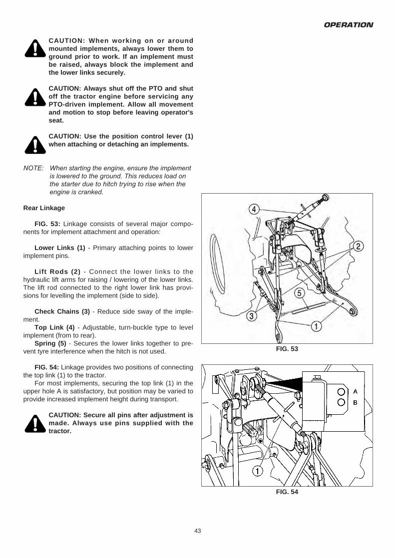
FIG. 53: Linkage consists of several major compo-nents for implement attachment and operation:
Lower Links (1) - Primary attaching points to lowerimplement pins.
Lift Rods (2) - Connect the lower l inks to thehydraulic lift arms for raising / lowering of the lower links.The lift rod connected to the right lower link has provi-sions for levelling the implement (side to side).
Check Chains (3) - Reduce side sway of the imple-ment.
Top Link (4) - Adjustable, turn-buckle type to levelimplement (from to rear).
Spring (5) - Secures the lower links together to pre-vent tyre interference when the hitch is not used.
FIG. 54: Linkage provides two positions of connectingthe top link (1) to the tractor.
For most implements, securing the top link (1) in theupper hole A is satisfactory, but position may be varied toprovide increased implement height during transport.
CAUTION: Secure all pins after adjustment ismade. Always use pins supplied with thetractor.
FIG. 53
FIG. 54
TM3160F,TM3200F&TM3240F
44
Attaching Implements
CAUTION: Always use POSITION CONTROLto attach / detach implements to provide pre-cise control of the hitch.
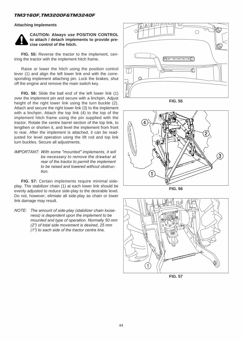
FIG. 55: Reverse the tractor to the implement, cen-tring the tractor with the implement hitch frame.
Raise or lower the hitch using the position controllever (1) and align the left lower link end with the corre-sponding implement attaching pin. Lock the brakes, shutoff the engine and remove the main switch key.
FIG. 56: Slide the ball end of the left lower link (1)over the implement pin and secure with a linchpin. Adjustheight of the right lower link using the turn buckle (2).Attach and secure the right lower link (3) to the implementwith a linchpin. Attach the top link (4) to the top of theimplement hitch frame using the pin supplied with thetractor. Rotate the centre barrel section of the top link, tolengthen or shorten it, and level the implement from frontto rear. After the implement is attached, it can be read-justed for level operation using the lift rod and top linkturn buckles. Secure all adjustments.
IMPORTANT: With some "mounted" implements, it will be necessary to remove the drawbar at rear of the tractor to permit the implement to be raised and lowered without obstruc-tion.
FIG. 57: Certain implements require minimal side-play. The stabilizer chain (1) at each lower link should beevenly adjusted to reduce side-play to the desirable level.Do not, however, elimiate all side-play as chain or lowerlink damage may result.
NOTE: The amount of side-play (stabilizer chain loose-ness) is dependent upon the implement to be mounted and type of operation. Normally 50 mm (2") of total side movement is desired, 25 mm (1") to each side of the tractor centre line.
FIG. 55
FIG. 56
FIG. 57
OPERATION
45
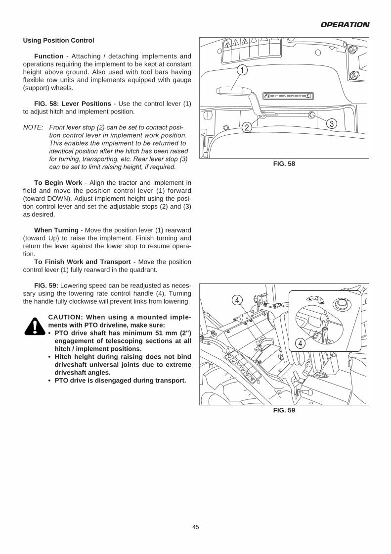
Using Position Control
Function - Attaching / detaching implements andoperations requiring the implement to be kept at constantheight above ground. Also used with tool bars havingflexible row units and implements equipped with gauge(support) wheels.
FIG. 58: Lever Positions - Use the control lever (1)to adjust hitch and implement position.
NOTE: Front lever stop (2) can be set to contact posi-tion control lever in implement work position. This enables the implement to be returned to identical position after the hitch has been raised for turning, transporting, etc. Rear lever stop (3) can be set to limit raising height, if required.
To Begin Work - Align the tractor and implement infield and move the position control lever (1) forward(toward DOWN). Adjust implement height using the posi-tion control lever and set the adjustable stops (2) and (3)as desired.
When Turning - Move the position lever (1) rearward(toward Up) to raise the implement. Finish turning andreturn the lever against the lower stop to resume opera-tion.
To Finish Work and Transport - Move the positioncontrol lever (1) fully rearward in the quadrant.
FIG. 59: Lowering speed can be readjusted as neces-sary using the lowering rate control handle (4). Turningthe handle fully clockwise will prevent links from lowering.
CAUTION: When using a mounted imple-ments with PTO driveline, make sure:• PTO drive shaft has minimum 51 mm (2")
engagement of telescoping sections at all hitch / implement positions.
• Hitch height during raising does not bind driveshaft universal joints due to extreme driveshaft angles.
• PTO drive is disengaged during transport.
FIG. 58
FIG. 59
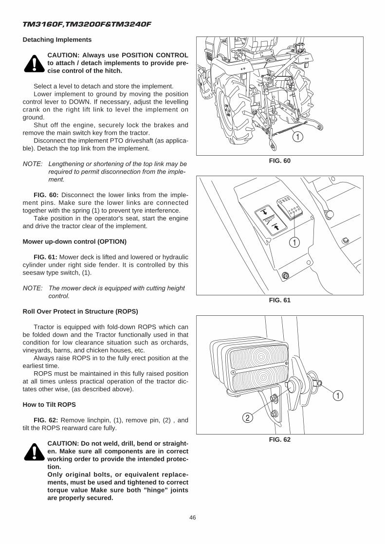
TM3160F,TM3200F&TM3240F
46
Detaching Implements
CAUTION: Always use POSITION CONTROLto attach / detach implements to provide pre-cise control of the hitch.
Select a level to detach and store the implement.Lower implement to ground by moving the position
control lever to DOWN. If necessary, adjust the levellingcrank on the right lift link to level the implement onground.
Shut off the engine, securely lock the brakes andremove the main switch key from the tractor.
Disconnect the implement PTO driveshaft (as applica-ble). Detach the top link from the implement.
NOTE: Lengthening or shortening of the top link may be required to permit disconnection from the imple-ment.
FIG. 60: Disconnect the lower links from the imple-ment pins. Make sure the lower links are connectedtogether with the spring (1) to prevent tyre interference.
Take position in the operator's seat, start the engineand drive the tractor clear of the implement.
Mower up-down control (OPTION)
FIG. 61: Mower deck is lifted and lowered or hydrauliccylinder under right side fender. It is controlled by thisseesaw type switch, (1).
NOTE: The mower deck is equipped with cutting height control.
Roll Over Protect in Structure (ROPS)
Tractor is equipped with fold-down ROPS which canbe folded down and the Tractor functionally used in thatcondition for low clearance situation such as orchards,vineyards, barns, and chicken houses, etc.
Always raise ROPS in to the fully erect position at theearliest time.
ROPS must be maintained in this fully raised positionat all times unless practical operation of the tractor dic-tates other wise, (as described above).
How to Tilt ROPS
FIG. 62: Remove linchpin, (1), remove pin, (2) , andtilt the ROPS rearward care fully.
CAUTION: Do not weld, drill, bend or straight-en. Make sure all components are in correctworking order to provide the intended protec-tion.Only original bolts, or equivalent replace-ments, must be used and tightened to correcttorque value Make sure both "hinge" jointsare properly secured.
FIG. 60
FIG. 61
FIG. 62
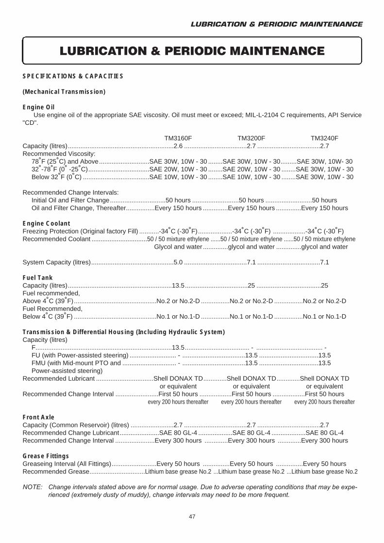
LUBRICATION & PERIODIC MAINTENANCE
47
SPECIFICATIONS & CAPACITIES
(Mechanical Transmission)
Engine OilUse engine oil of the appropriate SAE viscosity. Oil must meet or exceed; MIL-L-2104 C requirements, API Service
"CD".
TM3160F TM3200F TM3240FCapacity (litres)...........................................................2.6 ...................................2.7 ...................................2.7Recommended Viscosity:
78˚F (25˚C) and Above............................SAE 30W, 10W - 30 ........SAE 30W, 10W - 30.........SAE 30W, 10W- 3032˚-78˚F (0˚ -25˚C)..................................SAE 20W, 10W - 30 ........SAE 20W, 10W - 30 ........SAE 30W, 10W - 30Below 32˚F (0˚C) .....................................SAE 10W, 10W - 30 ........SAE 10W, 10W - 30 ........SAE 30W, 10W - 30
Recommended Change Intervals:Initial Oil and Filter Change...............................50 hours ..........................50 hours ..........................50 hoursOil and Filter Change, Thereafter................Every 150 hours ..............Every 150 hours ..............Every 150 hours
Engine CoolantFreezing Protection (Original factory Fill) ...........-34˚C (-30˚F)...................-34˚C (-30˚F) ..................-34˚C (-30˚F)Recommended Coolant ...............................50 / 50 mixture ethylene ......50 / 50 mixture ethylene ......50 / 50 mixture ethylene
Glycol and water ..............glycol and water ..............glycol and water
System Capacity (litres)..............................................5.0 ...................................7.1 ...................................7.1
Fuel TankCapacity (litres)..........................................................13.5...................................25 ....................................25Fuel recommended,Above 4˚C (39˚F)..............................................No.2 or No.2-D ................No.2 or No.2-D ................No.2 or No.2-DFuel Recommended,Below 4˚C (39˚F) ..............................................No.1 or No.1-D ................No.1 or No.1-D ................No.1 or No.1-D
Transmission & Differential Housing (Including Hydraulic System)Capacity (litres)
F............................................................................13.5.................................... - ..................................... -FU (with Power-assisted steering) .......................... - ...................................13.5 .................................13.5FMU (with Mid-mount PTO and .............................. - ...................................13.5 .................................13.5Power-assisted steering)
Recommended Lubricant ................................Shell DONAX TD.............Shell DONAX TD.............Shell DONAX TDor equivalent or equivalent or equivalent
Recommended Change Interval ........................First 50 hours ..................First 50 hours ..................First 50 hoursevery 200 hours thereafter every 200 hours thereafter every 200 hours thereafter
Front AxleCapacity (Common Reservoir) (litres) ........................2.7 ...................................2.7 ...................................2.7Recommended Change Lubricant......................SAE 80 GL-4 ...................SAE 80 GL-4 ...................SAE 80 GL-4Recommended Change Interval ......................Every 300 hours .............Every 300 hours .............Every 300 hours
Grease FittingsGreaseing Interval (All Fittings).........................Every 50 hours ...............Every 50 hours ...............Every 50 hours Recommended Grease...............................Lithium base grease No.2 ...Lithium base grease No.2 ...Lithium base grease No.2
NOTE: Change intervals stated above are for normal usage. Due to adverse operating conditions that may be expe-rienced (extremely dusty of muddy), change intervals may need to be more frequent.
LUBRICATION & PERIODIC MAINTENANCE
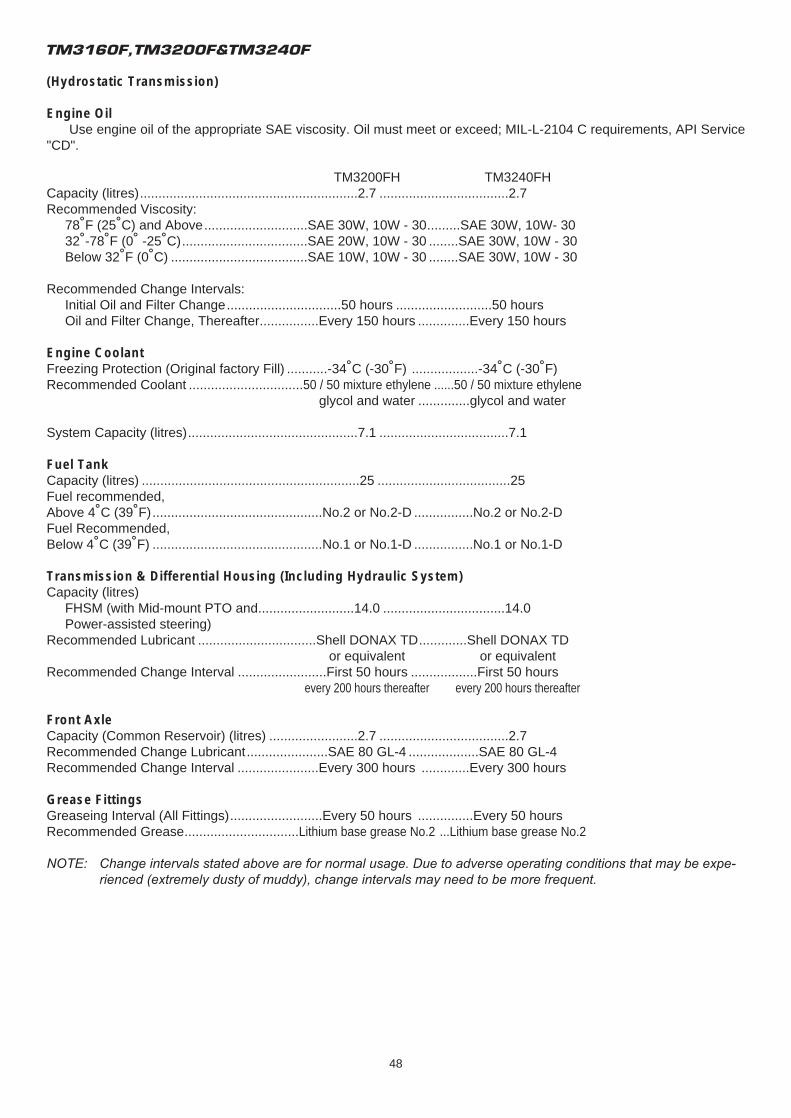
TM3160F,TM3200F&TM3240F
48
(Hydrostatic Transmission)
Engine OilUse engine oil of the appropriate SAE viscosity. Oil must meet or exceed; MIL-L-2104 C requirements, API Service
"CD".
TM3200FH TM3240FHCapacity (litres)...........................................................2.7 ...................................2.7Recommended Viscosity:
78˚F (25˚C) and Above............................SAE 30W, 10W - 30.........SAE 30W, 10W- 3032˚-78˚F (0˚ -25˚C)..................................SAE 20W, 10W - 30 ........SAE 30W, 10W - 30Below 32˚F (0˚C) .....................................SAE 10W, 10W - 30 ........SAE 30W, 10W - 30
Recommended Change Intervals:Initial Oil and Filter Change...............................50 hours ..........................50 hoursOil and Filter Change, Thereafter................Every 150 hours ..............Every 150 hours
Engine CoolantFreezing Protection (Original factory Fill) ...........-34˚C (-30˚F) ..................-34˚C (-30˚F)Recommended Coolant ...............................50 / 50 mixture ethylene ......50 / 50 mixture ethylene
glycol and water ..............glycol and water
System Capacity (litres)..............................................7.1 ...................................7.1
Fuel TankCapacity (litres) ...........................................................25 ....................................25Fuel recommended,Above 4˚C (39˚F)..............................................No.2 or No.2-D ................No.2 or No.2-DFuel Recommended,Below 4˚C (39˚F) ..............................................No.1 or No.1-D ................No.1 or No.1-D
Transmission & Differential Housing (Including Hydraulic System)Capacity (litres)
FHSM (with Mid-mount PTO and..........................14.0 .................................14.0Power-assisted steering)
Recommended Lubricant ................................Shell DONAX TD.............Shell DONAX TDor equivalent or equivalent
Recommended Change Interval ........................First 50 hours ..................First 50 hoursevery 200 hours thereafter every 200 hours thereafter
Front AxleCapacity (Common Reservoir) (litres) ........................2.7 ...................................2.7Recommended Change Lubricant......................SAE 80 GL-4 ...................SAE 80 GL-4Recommended Change Interval ......................Every 300 hours .............Every 300 hours
Grease FittingsGreaseing Interval (All Fittings).........................Every 50 hours ...............Every 50 hours Recommended Grease...............................Lithium base grease No.2 ...Lithium base grease No.2
NOTE: Change intervals stated above are for normal usage. Due to adverse operating conditions that may be expe-rienced (extremely dusty of muddy), change intervals may need to be more frequent.
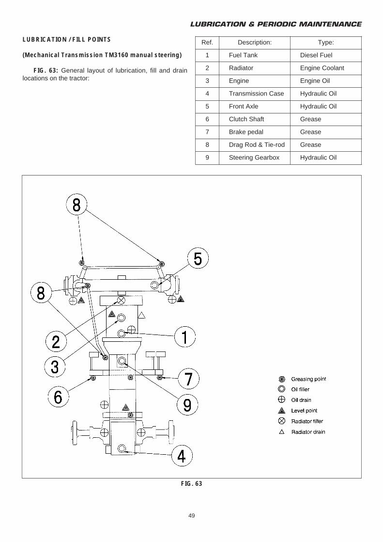
LUBRICATION & PERIODIC MAINTENANCE
49
LUBRICATION / FILL POINTS
(Mechanical Transmission TM3160 manual steering)
FIG. 63: General layout of lubrication, fill and drainlocations on the tractor:
FIG. 63
Ref. Description: Type:
1 Fuel Tank Diesel Fuel
2 Radiator Engine Coolant
3 Engine Engine Oil
4 Transmission Case Hydraulic Oil
5 Front Axle Hydraulic Oil
6 Clutch Shaft Grease
7 Brake pedal Grease
8 Drag Rod & Tie-rod Grease
9 Steering Gearbox Hydraulic Oil
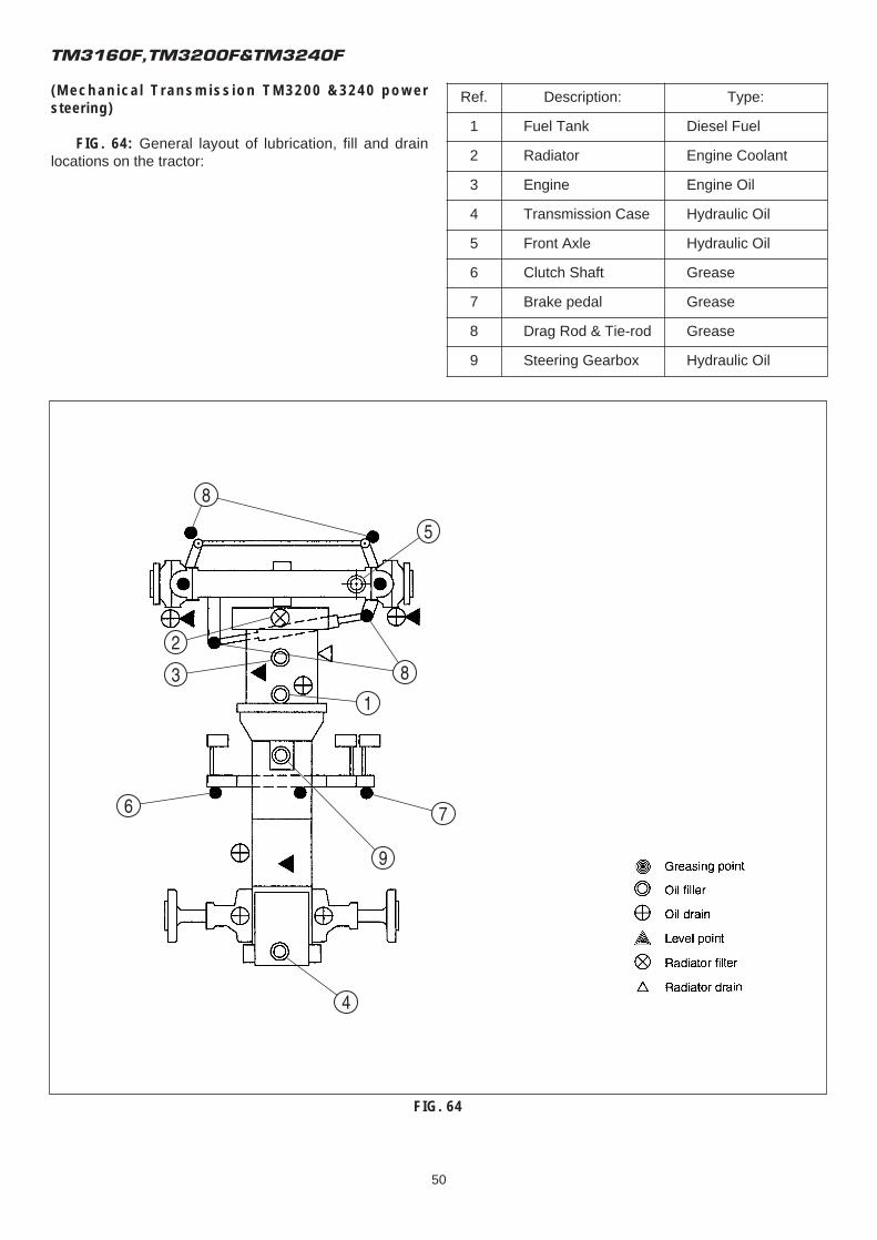
TM3160F,TM3200F&TM3240F
50
(Mechanical Transmission TM3200 &3240 powersteering)
FIG. 64: General layout of lubrication, fill and drainlocations on the tractor:
FIG. 64
Ref. Description: Type:
1 Fuel Tank Diesel Fuel
2 Radiator Engine Coolant
3 Engine Engine Oil
4 Transmission Case Hydraulic Oil
5 Front Axle Hydraulic Oil
6 Clutch Shaft Grease
7 Brake pedal Grease
8 Drag Rod & Tie-rod Grease
9 Steering Gearbox Hydraulic Oil
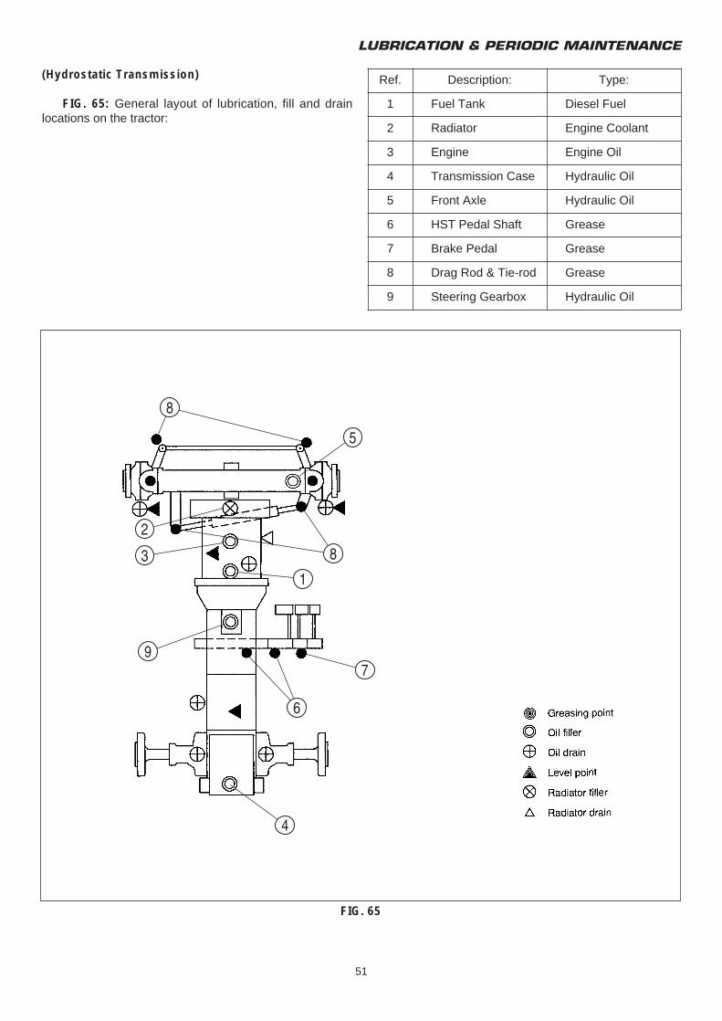
LUBRICATION & PERIODIC MAINTENANCE
51
(Hydrostatic Transmission)
FIG. 65: General layout of lubrication, fill and drainlocations on the tractor:
FIG. 65
Ref. Description: Type:
1 Fuel Tank Diesel Fuel
2 Radiator Engine Coolant
3 Engine Engine Oil
4 Transmission Case Hydraulic Oil
5 Front Axle Hydraulic Oil
6 HST Pedal Shaft Grease
7 Brake Pedal Grease
8 Drag Rod & Tie-rod Grease
9 Steering Gearbox Hydraulic Oil
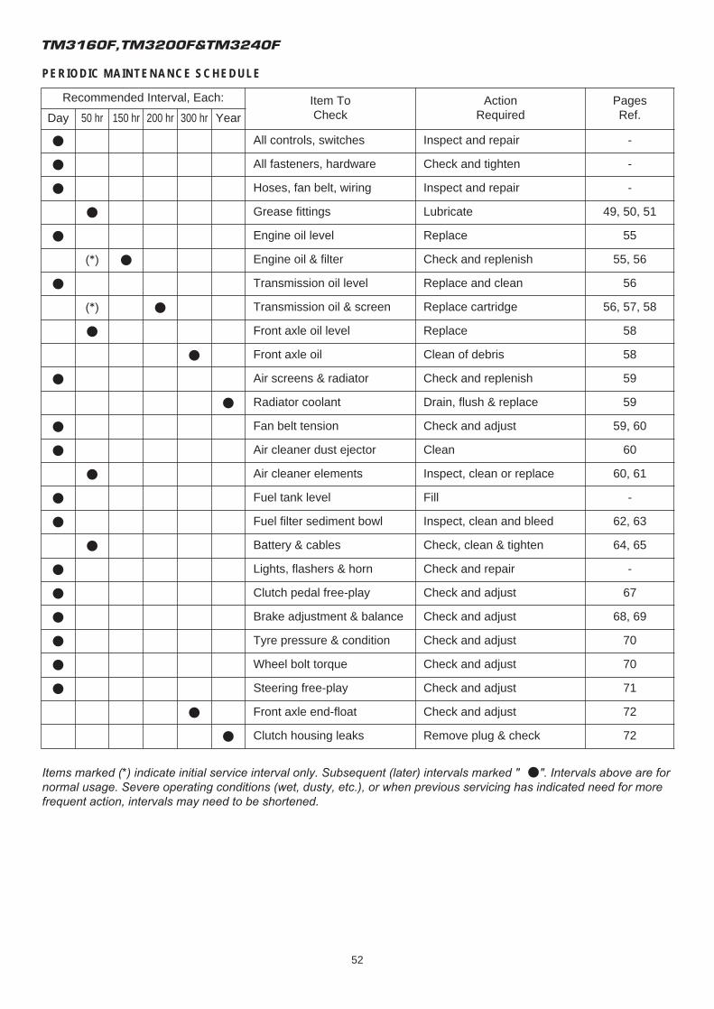
TM3160F,TM3200F&TM3240F
52
PERIODIC MAINTENANCE SCHEDULE
Items marked (*) indicate initial service interval only. Subsequent (later) intervals marked " ●". Intervals above are fornormal usage. Severe operating conditions (wet, dusty, etc.), or when previous servicing has indicated need for morefrequent action, intervals may need to be shortened.
Recommended Interval, Each: Item ToCheck
ActionRequired
PagesRef.Day 50 hr 150 hr 200 hr 300 hr Year
● All controls, switches Inspect and repair -
● All fasteners, hardware Check and tighten -
● Hoses, fan belt, wiring Inspect and repair -
● Grease fittings Lubricate 49, 50, 51
● Engine oil level Replace 55
(*) ● Engine oil & filter Check and replenish 55, 56
● Transmission oil level Replace and clean 56
(*) ● Transmission oil & screen Replace cartridge 56, 57, 58
● Front axle oil level Replace 58
● Front axle oil Clean of debris 58
● Air screens & radiator Check and replenish 59
● Radiator coolant Drain, flush & replace 59
● Fan belt tension Check and adjust 59, 60
● Air cleaner dust ejector Clean 60
● Air cleaner elements Inspect, clean or replace 60, 61
● Fuel tank level Fill -
● Fuel filter sediment bowl Inspect, clean and bleed 62, 63
● Battery & cables Check, clean & tighten 64, 65
● Lights, flashers & horn Check and repair -
● Clutch pedal free-play Check and adjust 67
● Brake adjustment & balance Check and adjust 68, 69
● Tyre pressure & condition Check and adjust 70
● Wheel bolt torque Check and adjust 70
● Steering free-play Check and adjust 71
● Front axle end-float Check and adjust 72
● Clutch housing leaks Remove plug & check 72
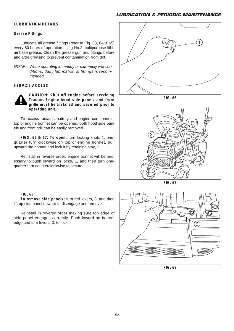
LUBRICATION & PERIODIC MAINTENANCE
53
LUBRICATION DETAILS
Grease Fittings
Lubricate all grease fittings (refer to Fig. 63, 64 & 65)every 50 hours of operation using No.2 multipurpose lithi-umbase grease. Clean the grease gun and fittings beforeand after greasing to prevent contamination from dirt.
NOTE: When operating in muddy or extremely wet con-ditions, daily lubrication of fittings is recom-mended.
SERVICE ACCESS
CAUTION: Shut off engine before servicingTractor. Engine hood side panels and frontgrille must be Installed and secured prior tooperating unit.
To access radiator, battery and engine components,top of engine bonnet can be opened, both hood side pan-els and front grill can be easily removed.
FIGS. 66 & 67: To open; turn locking knob, 1, one-quarter turn clockwise on top of engine bonnet, pullupward the bonnet and lock it by retaining stay, 2.
Reinstall in reverse order, engine bonnet will be nec-essary to push inward on locks, 1, and then turn one-quarter turn counterclockwise to secure.
FIG. 68:To remove side panels; turn red levers, 3, and then
lift up side panel upward to disengage and remove.
Reinstall in reverse order making sure top edge ofside panel engages correctly. Push inward on bottomedge and turn levers, 3, to lock.
FIG. 66
FIG. 67
FIG. 68

TM3160F,TM3200F&TM3240F
54
FIGS. 69 & 70:To remove front grill; unscrew locking knobs, 4, and
pull upward and outward to remove.Disconnect headlights wiring couplers, 5.
Reinstall in reverse order making sure front grill lowerprojections engage on holes.
FIG. 69
FIG. 70
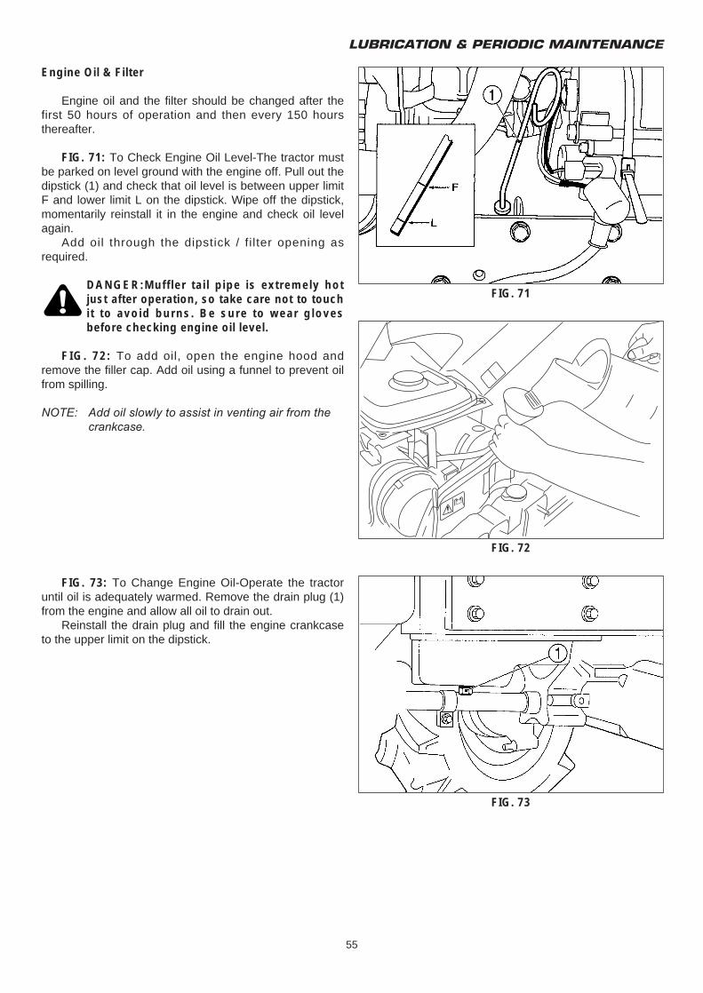
LUBRICATION & PERIODIC MAINTENANCE
55
Engine Oil & Filter
Engine oil and the filter should be changed after thefirst 50 hours of operation and then every 150 hoursthereafter.
FIG. 71: To Check Engine Oil Level-The tractor mustbe parked on level ground with the engine off. Pull out thedipstick (1) and check that oil level is between upper limitF and lower limit L on the dipstick. Wipe off the dipstick,momentarily reinstall it in the engine and check oil levelagain.
Add oil through the dipstick / fi lter opening asrequired.
DANGER:Muffler tail pipe is extremely hotjust after operation, so take care not to touchit to avoid burns. Be sure to wear glovesbefore checking engine oil level.
FIG. 72: To add oil, open the engine hood andremove the filler cap. Add oil using a funnel to prevent oilfrom spilling.
NOTE: Add oil slowly to assist in venting air from the crankcase.
FIG. 73: To Change Engine Oil-Operate the tractoruntil oil is adequately warmed. Remove the drain plug (1)from the engine and allow all oil to drain out.
Reinstall the drain plug and fill the engine crankcaseto the upper limit on the dipstick.
FIG. 71
FIG. 72
FIG. 73
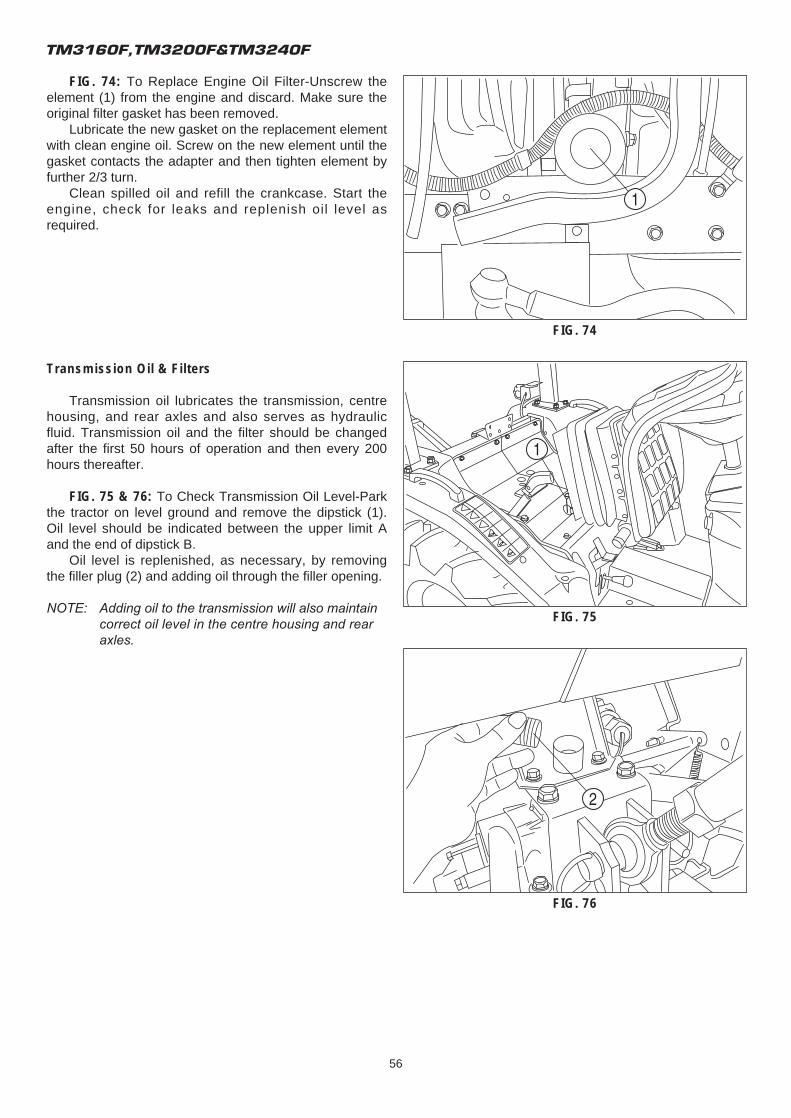
TM3160F,TM3200F&TM3240F
56
FIG. 74: To Replace Engine Oil Filter-Unscrew theelement (1) from the engine and discard. Make sure theoriginal filter gasket has been removed.
Lubricate the new gasket on the replacement elementwith clean engine oil. Screw on the new element until thegasket contacts the adapter and then tighten element byfurther 2/3 turn.
Clean spilled oil and refill the crankcase. Start theengine, check for leaks and replenish oil level asrequired.
Transmission Oil & Filters
Transmission oil lubricates the transmission, centrehousing, and rear axles and also serves as hydraulicfluid. Transmission oil and the filter should be changedafter the first 50 hours of operation and then every 200hours thereafter.
FIG. 75 & 76: To Check Transmission Oil Level-Parkthe tractor on level ground and remove the dipstick (1).Oil level should be indicated between the upper limit Aand the end of dipstick B.
Oil level is replenished, as necessary, by removingthe filler plug (2) and adding oil through the filler opening.
NOTE: Adding oil to the transmission will also maintain correct oil level in the centre housing and rear axles.
FIG. 74
FIG. 75
FIG. 76
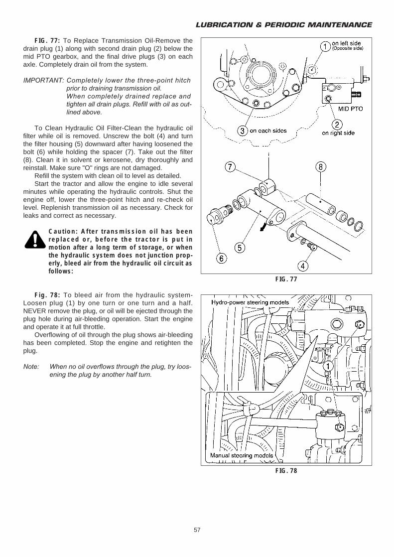
LUBRICATION & PERIODIC MAINTENANCE
57
FIG. 77: To Replace Transmission Oil-Remove thedrain plug (1) along with second drain plug (2) below themid PTO gearbox, and the final drive plugs (3) on eachaxle. Completely drain oil from the system.
IMPORTANT: Completely lower the three-point hitch prior to draining transmission oil.When completely drained replace and tighten all drain plugs. Refill with oil as out-lined above.
To Clean Hydraulic Oil Filter-Clean the hydraulic oilfilter while oil is removed. Unscrew the bolt (4) and turnthe filter housing (5) downward after having loosened thebolt (6) while holding the spacer (7). Take out the filter(8). Clean it in solvent or kerosene, dry thoroughly andreinstall. Make sure "O" rings are not damaged.
Refill the system with clean oil to level as detailed.Start the tractor and allow the engine to idle several
minutes while operating the hydraulic controls. Shut theengine off, lower the three-point hitch and re-check oillevel. Replenish transmission oil as necessary. Check forleaks and correct as necessary.
Caution: After transmission oil has beenreplaced or, before the tractor is put inmotion after a long term of storage, or whenthe hydraulic system does not junction prop-erly, bleed air from the hydraulic oil circuit asfollows:
Fig. 78: To bleed air from the hydraulic system-Loosen plug (1) by one turn or one turn and a half.NEVER remove the plug, or oil will be ejected through theplug hole during air-bleeding operation. Start the engineand operate it at full throttle.
Overflowing of oil through the plug shows air-bleedinghas been completed. Stop the engine and retighten theplug.
Note: When no oil overflows through the plug, try loos-ening the plug by another half turn.
FIG. 77
FIG. 78
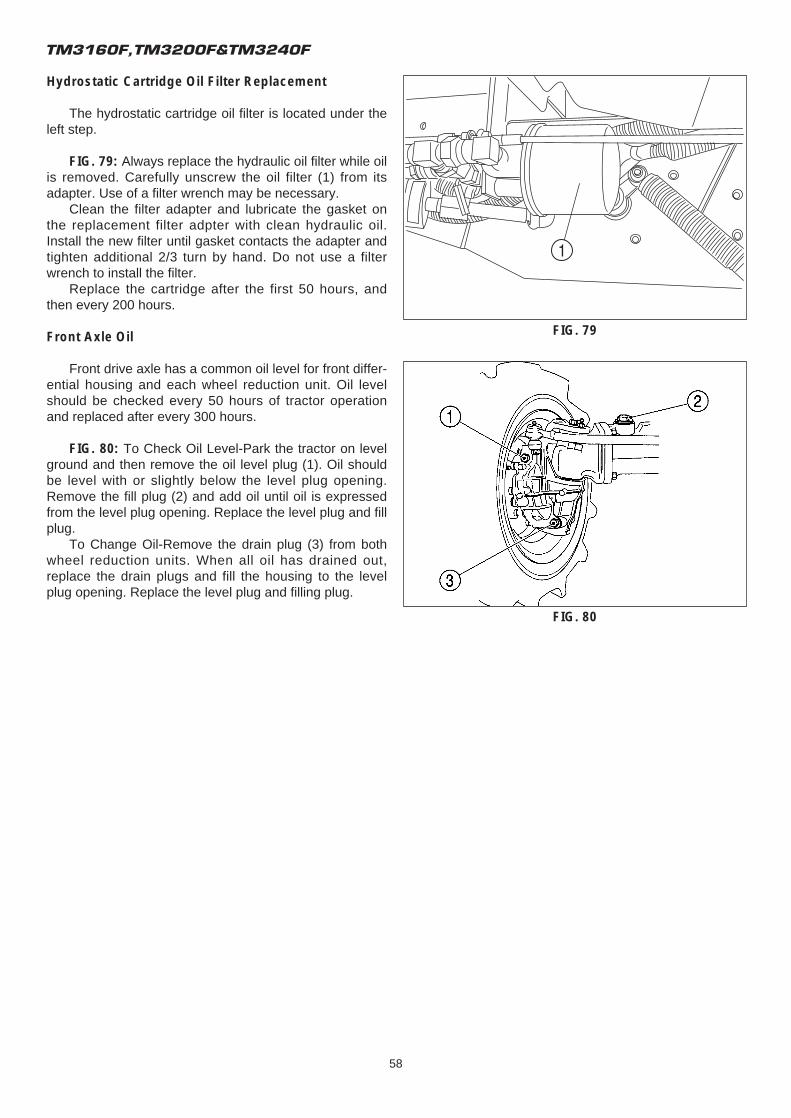
TM3160F,TM3200F&TM3240F
58
Hydrostatic Cartridge Oil Filter Replacement
The hydrostatic cartridge oil filter is located under theleft step.
FIG. 79: Always replace the hydraulic oil filter while oilis removed. Carefully unscrew the oil filter (1) from itsadapter. Use of a filter wrench may be necessary.
Clean the filter adapter and lubricate the gasket onthe replacement filter adpter with clean hydraulic oil.Install the new filter until gasket contacts the adapter andtighten additional 2/3 turn by hand. Do not use a filterwrench to install the filter.
Replace the cartridge after the first 50 hours, andthen every 200 hours.
Front Axle Oil
Front drive axle has a common oil level for front differ-ential housing and each wheel reduction unit. Oil levelshould be checked every 50 hours of tractor operationand replaced after every 300 hours.
FIG. 80: To Check Oil Level-Park the tractor on levelground and then remove the oil level plug (1). Oil shouldbe level with or slightly below the level plug opening.Remove the fill plug (2) and add oil until oil is expressedfrom the level plug opening. Replace the level plug and fillplug.
To Change Oil-Remove the drain plug (3) from bothwheel reduction units. When all oil has drained out,replace the drain plugs and fill the housing to the levelplug opening. Replace the level plug and filling plug.
FIG. 79
FIG. 80
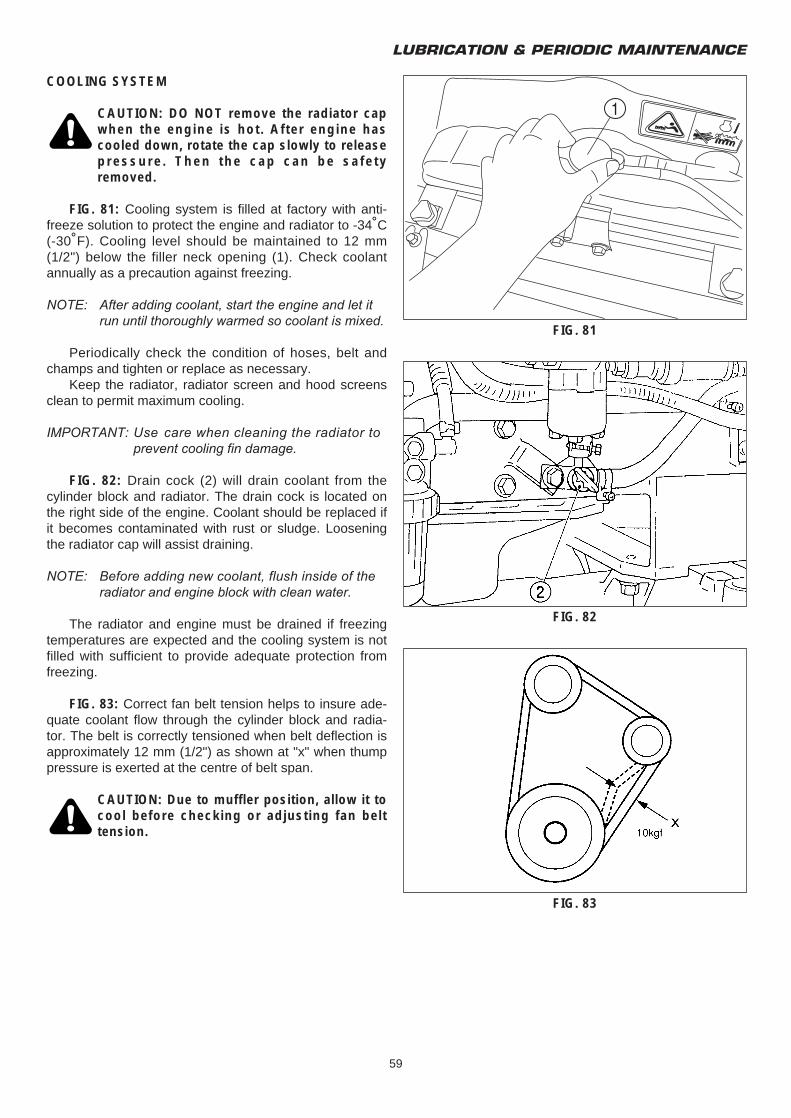
LUBRICATION & PERIODIC MAINTENANCE
59
COOLING SYSTEM
CAUTION: DO NOT remove the radiator capwhen the engine is hot. After engine hascooled down, rotate the cap slowly to releasepressure. Then the cap can be safetyremoved.
FIG. 81: Cooling system is filled at factory with anti-freeze solution to protect the engine and radiator to -34˚C(-30˚F). Cooling level should be maintained to 12 mm(1/2") below the filler neck opening (1). Check coolantannually as a precaution against freezing.
NOTE: After adding coolant, start the engine and let it run until thoroughly warmed so coolant is mixed.
Periodically check the condition of hoses, belt andchamps and tighten or replace as necessary.
Keep the radiator, radiator screen and hood screensclean to permit maximum cooling.
IMPORTANT: Use care when cleaning the radiator to prevent cooling fin damage.
FIG. 82: Drain cock (2) will drain coolant from thecylinder block and radiator. The drain cock is located onthe right side of the engine. Coolant should be replaced ifit becomes contaminated with rust or sludge. Looseningthe radiator cap will assist draining.
NOTE: Before adding new coolant, flush inside of the radiator and engine block with clean water.
The radiator and engine must be drained if freezingtemperatures are expected and the cooling system is notfilled with sufficient to provide adequate protection fromfreezing.
FIG. 83: Correct fan belt tension helps to insure ade-quate coolant flow through the cylinder block and radia-tor. The belt is correctly tensioned when belt deflection isapproximately 12 mm (1/2") as shown at "x" when thumppressure is exerted at the centre of belt span.
CAUTION: Due to muffler position, allow it tocool before checking or adjusting fan belttension.
FIG. 81
FIG. 82
FIG. 83
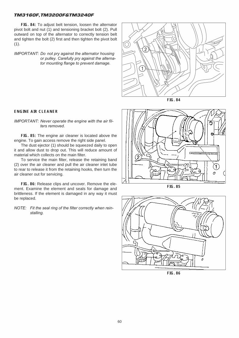
TM3160F,TM3200F&TM3240F
60
FIG. 84: To adjust belt tension, loosen the alternatorpivot bolt and nut (1) and tensioning bracket bolt (2). Pulloutward on top of the alternator to correctly tension beltand tighten the bolt (2) first and then tighten the pivot bolt(1).
IMPORTANT: Do not pry against the alternator housing or pulley. Carefully pry against the alterna-tor mounting flange to prevent damage.
ENGINE AIR CLEANER
IMPORTANT: Never operate the engine with the air fil-ters removed.
FIG. 85: The engine air cleaner is located above theengine. To gain access remove the right side panel.
The dust ejector (1) should be squeezed daily to openit and allow dust to drop out. This will reduce amount ofmaterial which collects on the main filter.
To service the main filter, release the retaining band(2) over the air cleaner and pull the air cleaner inlet tubeto rear to release it from the retaining hooks, then turn theair cleaner out for servicing.
FIG. 86: Release clips and uncover. Remove the ele-ment. Examine the element and seals for damage andbrittleness. If the element is damaged in any way it mustbe replaced.
NOTE: Fit the seal ring of the filter correctly when rein-stalling.
FIG. 85
FIG. 84
FIG. 86
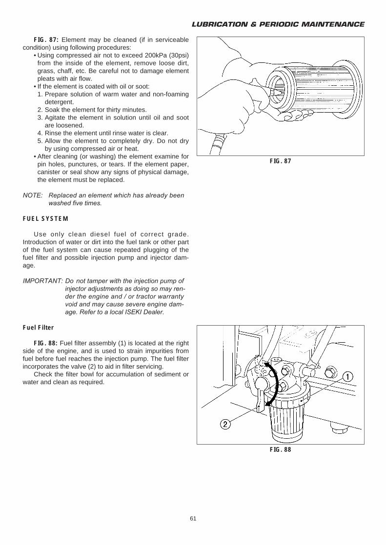
LUBRICATION & PERIODIC MAINTENANCE
61
FIG. 87: Element may be cleaned (if in serviceablecondition) using following procedures:
• Using compressed air not to exceed 200kPa (30psi) from the inside of the element, remove loose dirt, grass, chaff, etc. Be careful not to damage element pleats with air flow.
• If the element is coated with oil or soot:1. Prepare solution of warm water and non-foaming
detergent.2. Soak the element for thirty minutes.3. Agitate the element in solution until oil and soot
are loosened.4. Rinse the element until rinse water is clear.5. Allow the element to completely dry. Do not dry
by using compressed air or heat.• After cleaning (or washing) the element examine for
pin holes, punctures, or tears. If the element paper, canister or seal show any signs of physical damage, the element must be replaced.
NOTE: Replaced an element which has already been washed five times.
FUEL SYSTEM
Use only clean diesel fuel of correct grade.Introduction of water or dirt into the fuel tank or other partof the fuel system can cause repeated plugging of thefuel filter and possible injection pump and injector dam-age.
IMPORTANT: Do not tamper with the injection pump of injector adjustments as doing so may ren-der the engine and / or tractor warranty void and may cause severe engine dam-age. Refer to a local ISEKI Dealer.
Fuel Filter
FIG. 88: Fuel filter assembly (1) is located at the rightside of the engine, and is used to strain impurities fromfuel before fuel reaches the injection pump. The fuel filterincorporates the valve (2) to aid in filter servicing.
Check the filter bowl for accumulation of sediment orwater and clean as required.
FIG. 88
FIG. 87
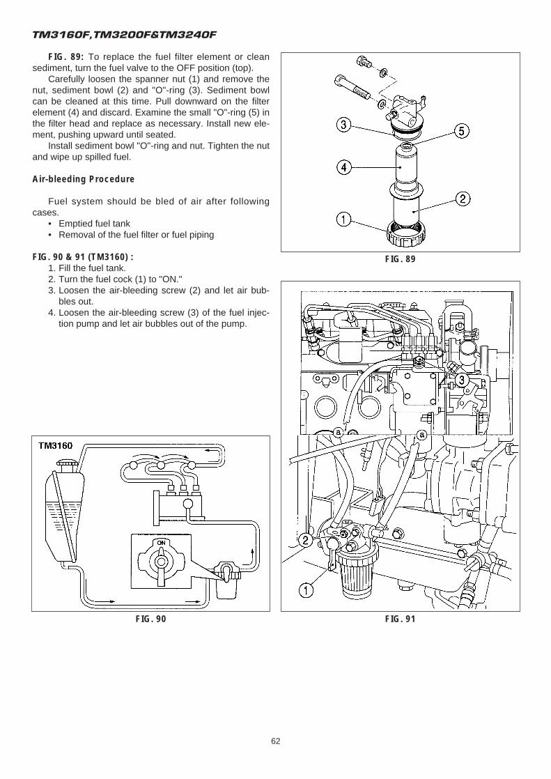
TM3160F,TM3200F&TM3240F
62
FIG. 89: To replace the fuel filter element or cleansediment, turn the fuel valve to the OFF position (top).
Carefully loosen the spanner nut (1) and remove thenut, sediment bowl (2) and "O"-ring (3). Sediment bowlcan be cleaned at this time. Pull downward on the filterelement (4) and discard. Examine the small "O"-ring (5) inthe filter head and replace as necessary. Install new ele-ment, pushing upward until seated.
Install sediment bowl "O"-ring and nut. Tighten the nutand wipe up spilled fuel.
Air-bleeding Procedure
Fuel system should be bled of air after followingcases.
• Emptied fuel tank• Removal of the fuel filter or fuel piping
FIG. 90 & 91 (TM3160) :1. Fill the fuel tank.2. Turn the fuel cock (1) to "ON."3. Loosen the air-bleeding screw (2) and let air bub-
bles out.4. Loosen the air-bleeding screw (3) of the fuel injec-
tion pump and let air bubbles out of the pump.
FIG. 90 FIG. 91
FIG. 89
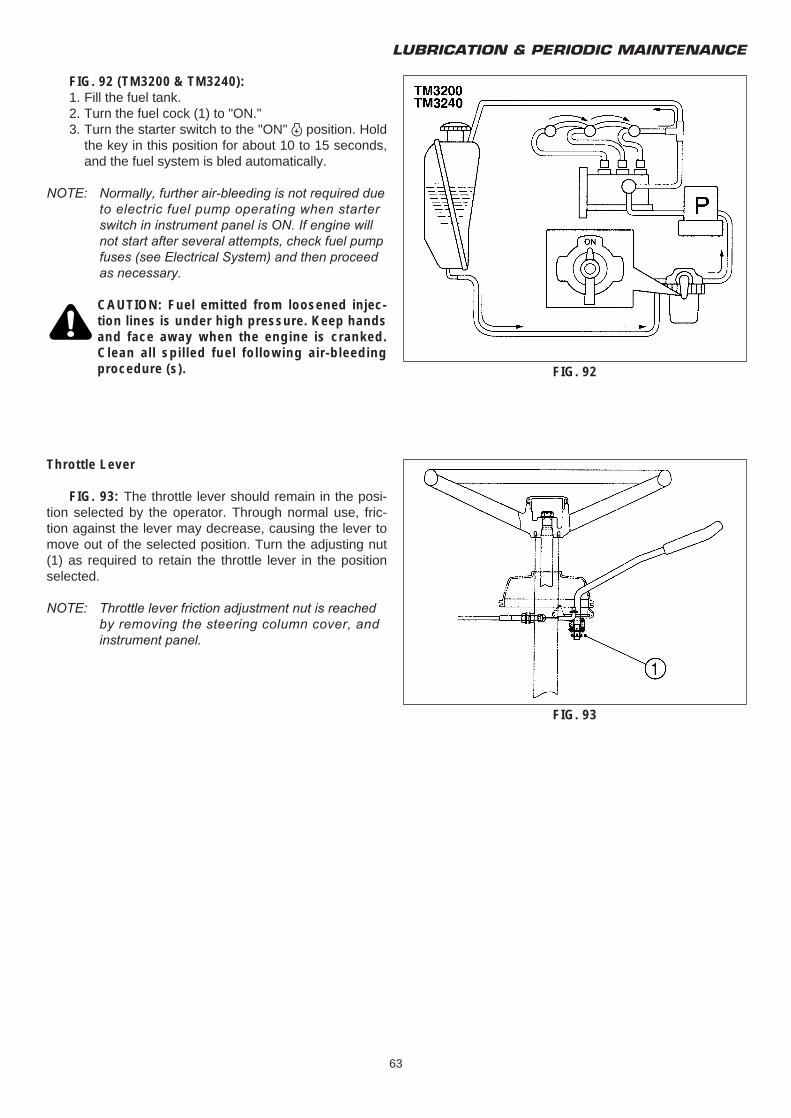
LUBRICATION & PERIODIC MAINTENANCE
63
FIG. 92 (TM3200 & TM3240):1. Fill the fuel tank.2. Turn the fuel cock (1) to "ON."3. Turn the starter switch to the "ON" O position. Hold
the key in this position for about 10 to 15 seconds, and the fuel system is bled automatically.
NOTE: Normally, further air-bleeding is not required due to electric fuel pump operating when starter switch in instrument panel is ON. If engine will not start after several attempts, check fuel pump fuses (see Electrical System) and then proceed as necessary.
CAUTION: Fuel emitted from loosened injec-tion lines is under high pressure. Keep handsand face away when the engine is cranked.Clean all spilled fuel following air-bleedingprocedure (s).
Throttle Lever
FIG. 93: The throttle lever should remain in the posi-tion selected by the operator. Through normal use, fric-tion against the lever may decrease, causing the lever tomove out of the selected position. Turn the adjusting nut(1) as required to retain the throttle lever in the positionselected.
NOTE: Throttle lever friction adjustment nut is reached by removing the steering column cover, and instrument panel.
FIG. 92
FIG. 93
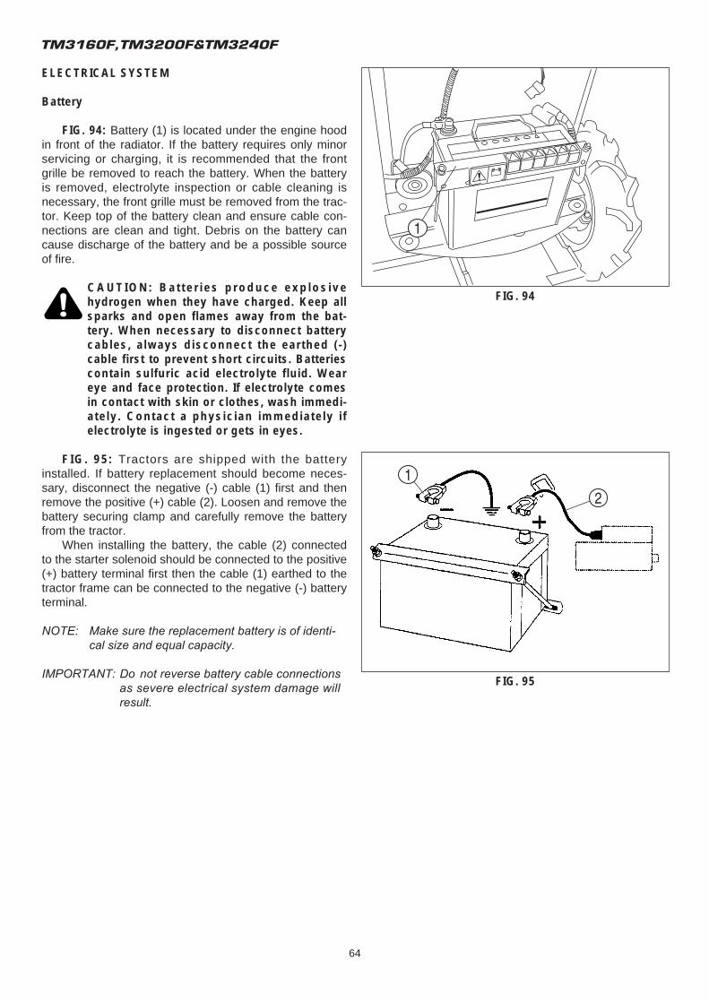
TM3160F,TM3200F&TM3240F
64
ELECTRICAL SYSTEM
Battery
FIG. 94: Battery (1) is located under the engine hoodin front of the radiator. If the battery requires only minorservicing or charging, it is recommended that the frontgrille be removed to reach the battery. When the batteryis removed, electrolyte inspection or cable cleaning isnecessary, the front grille must be removed from the trac-tor. Keep top of the battery clean and ensure cable con-nections are clean and tight. Debris on the battery cancause discharge of the battery and be a possible sourceof fire.
CAUTION: Batteries produce explosivehydrogen when they have charged. Keep allsparks and open flames away from the bat-tery. When necessary to disconnect batterycables, always disconnect the earthed (-)cable first to prevent short circuits. Batteriescontain sulfuric acid electrolyte fluid. Weareye and face protection. If electrolyte comesin contact with skin or clothes, wash immedi-ately. Contact a physician immediately ifelectrolyte is ingested or gets in eyes.
FIG. 95: Tractors are shipped with the batteryinstalled. If battery replacement should become neces-sary, disconnect the negative (-) cable (1) first and thenremove the positive (+) cable (2). Loosen and remove thebattery securing clamp and carefully remove the batteryfrom the tractor.
When installing the battery, the cable (2) connectedto the starter solenoid should be connected to the positive(+) battery terminal first then the cable (1) earthed to thetractor frame can be connected to the negative (-) batteryterminal.
NOTE: Make sure the replacement battery is of identi-cal size and equal capacity.
IMPORTANT: Do not reverse battery cable connections as severe electrical system damage will result.
FIG. 94
FIG. 95
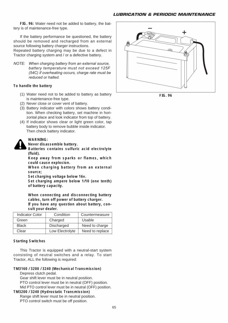
LUBRICATION & PERIODIC MAINTENANCE
65
FIG. 96: Water need not be added to battery, the bat-tery is of maintenance-free type.
If the battery performance be questioned, the batteryshould be removed and recharged from an externalsource following battery charger instructions.Repeated battery charging may be due to a defect inTractor charging system and / or a defective battery.
NOTE: When charging battery from an external source, battery temperature must not exceed 125F (54C) if overheating occurs, charge rate must be reduced or halted.
To handle the battery
(1) Water need not to be added to battery as battery is maintenance-free type.
(2) Never close or cover vent of battery.(3) Battery indicator with colors shows battery condi-
tion. When checking battery, set machine in hori-zontal place and look indicator from top of battery.
(4) If indicator shows clear or light green color, tap battery body to remove bubble inside indicator.Then check battery indicator.
WARNING:Never disassemble battery.Batteries contains sulfuric acid electrolyte(fluid).Keep away from sparks or flames, whichcould cause explosion.When charging battery from an externalsource;Set charging voltage below 16v.Set charging ampere below 1/10 (one tenth)of battery capacity.
When connecting and disconnecting batterycables, turn off power of battery charger.If you have any question about battery, con-sult your dealer.
Starting Switches
This Tractor is equipped with a neutral-start systemconsisting of neutral switches and a relay. To startTractor, ALL the following is required:
TM3160 / 3200 / 3240 (Mechanical Transmission)Depress clutch pedal.Gear shift lever must be in neutral position.PTO control lever must be in neutral (OFF) position.Mid PTO control lever must be in neutral (OFF) position.
TM3200 / 3240 (Hydrostatic Transmission)Range shift lever must be in neutral position.PTO control switch must be off position.
FIG. 96
Indicator Color Condition CountermeasureGreen Charged UsableBlack Discharged Need to chargeClear Low Electrolyte Need to replace
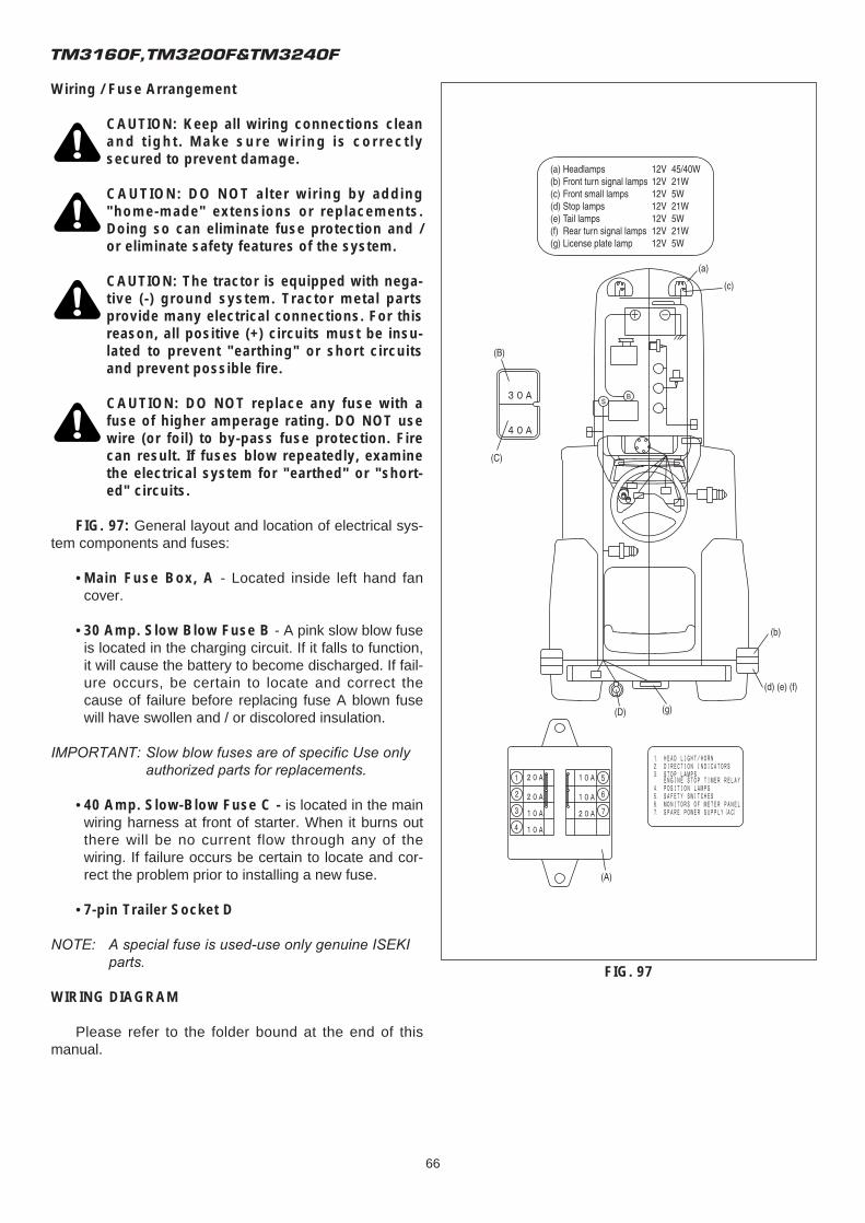
TM3160F,TM3200F&TM3240F
66
Wiring / Fuse Arrangement
CAUTION: Keep all wiring connections cleanand tight. Make sure wiring is correctlysecured to prevent damage.
CAUTION: DO NOT alter wiring by adding"home-made" extensions or replacements.Doing so can eliminate fuse protection and /or eliminate safety features of the system.
CAUTION: The tractor is equipped with nega-tive (-) ground system. Tractor metal partsprovide many electrical connections. For thisreason, all positive (+) circuits must be insu-lated to prevent "earthing" or short circuitsand prevent possible fire.
CAUTION: DO NOT replace any fuse with afuse of higher amperage rating. DO NOT usewire (or foil) to by-pass fuse protection. Firecan result. If fuses blow repeatedly, examinethe electrical system for "earthed" or "short-ed" circuits.
FIG. 97: General layout and location of electrical sys-tem components and fuses:
• Main Fuse Box, A - Located inside left hand fan cover.
• 30 Amp. Slow Blow Fuse B - A pink slow blow fuse is located in the charging circuit. If it falls to function, it will cause the battery to become discharged. If fail-ure occurs, be certain to locate and correct the cause of failure before replacing fuse A blown fuse will have swollen and / or discolored insulation.
IMPORTANT: Slow blow fuses are of specific Use only authorized parts for replacements.
• 40 Amp. Slow-Blow Fuse C - is located in the main wiring harness at front of starter. When it burns out there will be no current flow through any of the wiring. If failure occurs be certain to locate and cor-rect the problem prior to installing a new fuse.
• 7-pin Trailer Socket D
NOTE: A special fuse is used-use only genuine ISEKI parts.
WIRING DIAGRAM
Please refer to the folder bound at the end of thismanual.
FIG. 97
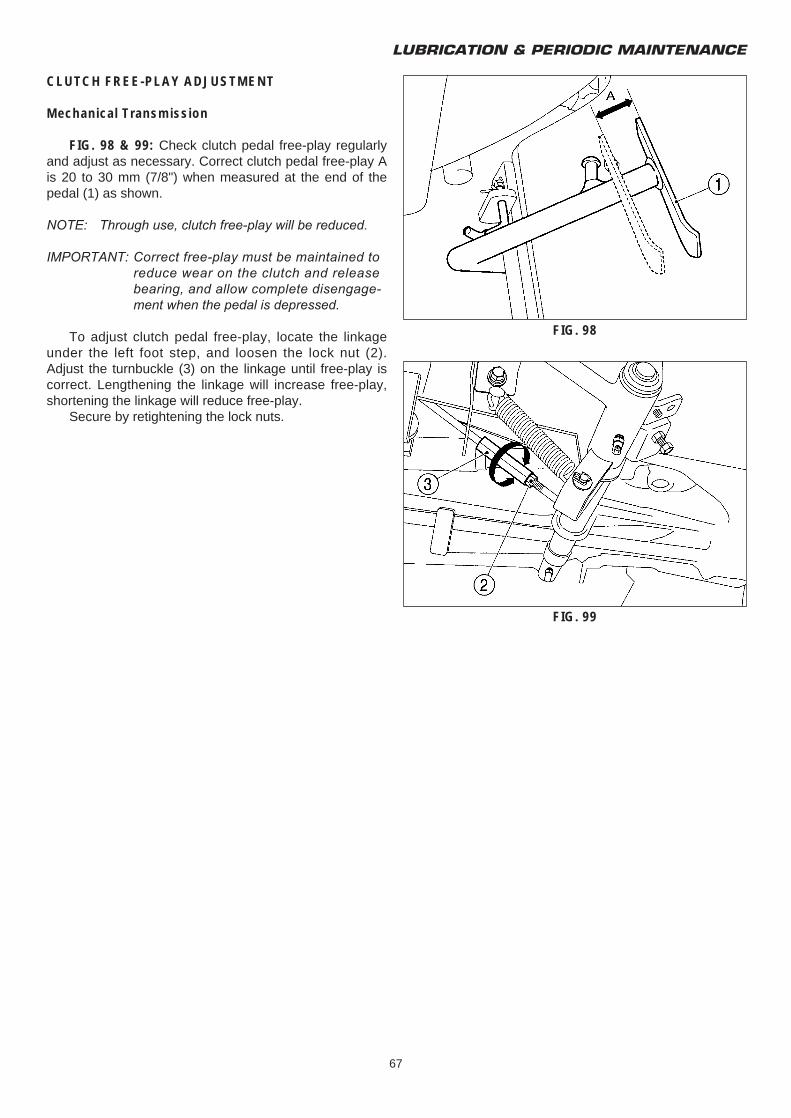
LUBRICATION & PERIODIC MAINTENANCE
67
CLUTCH FREE-PLAY ADJUSTMENT
Mechanical Transmission
FIG. 98 & 99: Check clutch pedal free-play regularlyand adjust as necessary. Correct clutch pedal free-play Ais 20 to 30 mm (7/8") when measured at the end of thepedal (1) as shown.
NOTE: Through use, clutch free-play will be reduced.
IMPORTANT: Correct free-play must be maintained to reduce wear on the clutch and release bearing, and allow complete disengage-ment when the pedal is depressed.
To adjust clutch pedal free-play, locate the linkageunder the left foot step, and loosen the lock nut (2).Adjust the turnbuckle (3) on the linkage until free-play iscorrect. Lengthening the linkage will increase free-play,shortening the linkage will reduce free-play.
Secure by retightening the lock nuts.
FIG. 98
FIG. 99
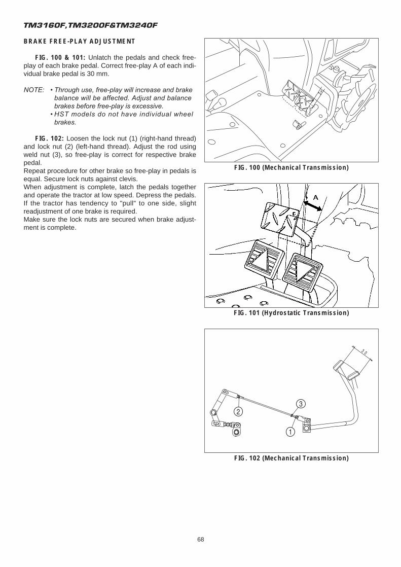
TM3160F,TM3200F&TM3240F
68
BRAKE FREE-PLAY ADJUSTMENT
FIG. 100 & 101: Unlatch the pedals and check free-play of each brake pedal. Correct free-play A of each indi-vidual brake pedal is 30 mm.
NOTE: • Through use, free-play will increase and brake balance will be affected. Adjust and balance brakes before free-play is excessive.
• HST models do not have individual wheel brakes.
FIG. 102: Loosen the lock nut (1) (right-hand thread)and lock nut (2) (left-hand thread). Adjust the rod usingweld nut (3), so free-play is correct for respective brakepedal.Repeat procedure for other brake so free-play in pedals isequal. Secure lock nuts against clevis.When adjustment is complete, latch the pedals togetherand operate the tractor at low speed. Depress the pedals.If the tractor has tendency to "pull" to one side, slightreadjustment of one brake is required.Make sure the lock nuts are secured when brake adjust-ment is complete.
FIG. 101 (Hydrostatic Transmission)
FIG. 102 (Mechanical Transmission)
FIG. 100 (Mechanical Transmission)
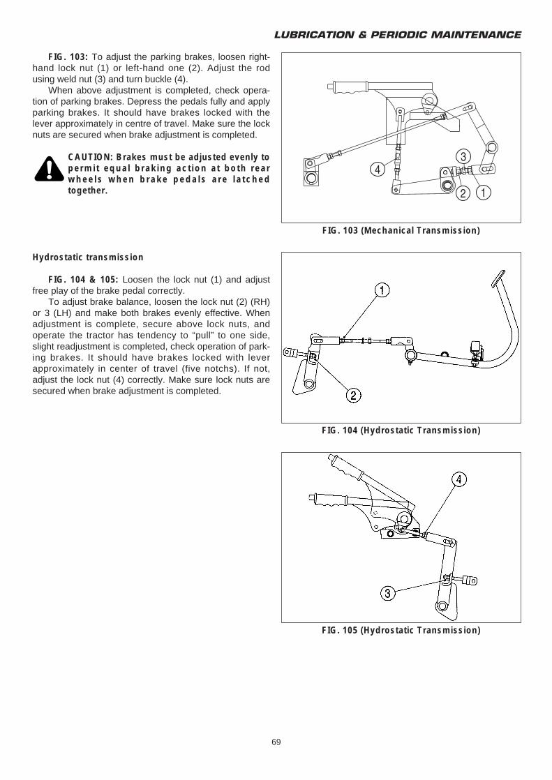
LUBRICATION & PERIODIC MAINTENANCE
69
FIG. 103: To adjust the parking brakes, loosen right-hand lock nut (1) or left-hand one (2). Adjust the rodusing weld nut (3) and turn buckle (4).
When above adjustment is completed, check opera-tion of parking brakes. Depress the pedals fully and applyparking brakes. It should have brakes locked with thelever approximately in centre of travel. Make sure the locknuts are secured when brake adjustment is completed.
CAUTION: Brakes must be adjusted evenly topermit equal braking action at both rearwheels when brake pedals are latchedtogether.
Hydrostatic transmission
FIG. 104 & 105: Loosen the lock nut (1) and adjustfree play of the brake pedal correctly.
To adjust brake balance, loosen the lock nut (2) (RH)or 3 (LH) and make both brakes evenly effective. Whenadjustment is complete, secure above lock nuts, andoperate the tractor has tendency to “pull” to one side,slight readjustment is completed, check operation of park-ing brakes. It should have brakes locked with leverapproximately in center of travel (five notchs). If not,adjust the lock nut (4) correctly. Make sure lock nuts aresecured when brake adjustment is completed.
FIG. 103 (Mechanical Transmission)
FIG. 104 (Hydrostatic Transmission)
FIG. 105 (Hydrostatic Transmission)
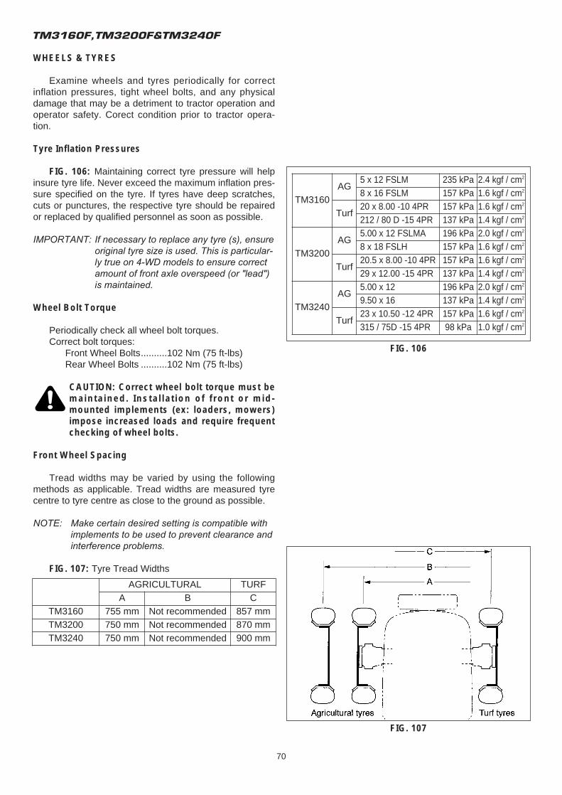
TM3160F,TM3200F&TM3240F
70
WHEELS & TYRES
Examine wheels and tyres periodically for correctinflation pressures, tight wheel bolts, and any physicaldamage that may be a detriment to tractor operation andoperator safety. Corect condition prior to tractor opera-tion.
Tyre Inflation Pressures
FIG. 106: Maintaining correct tyre pressure will helpinsure tyre life. Never exceed the maximum inflation pres-sure specified on the tyre. If tyres have deep scratches,cuts or punctures, the respective tyre should be repairedor replaced by qualified personnel as soon as possible.
IMPORTANT: If necessary to replace any tyre (s), ensure original tyre size is used. This is particular-ly true on 4-WD models to ensure correct amount of front axle overspeed (or "lead") is maintained.
Wheel Bolt Torque
Periodically check all wheel bolt torques.Correct bolt torques:
Front Wheel Bolts..........102 Nm (75 ft-lbs)Rear Wheel Bolts ..........102 Nm (75 ft-lbs)
CAUTION: Correct wheel bolt torque must bemaintained. Installation of front or mid-mounted implements (ex: loaders, mowers)impose increased loads and require frequentchecking of wheel bolts.
Front Wheel Spacing
Tread widths may be varied by using the followingmethods as applicable. Tread widths are measured tyrecentre to tyre centre as close to the ground as possible.
NOTE: Make certain desired setting is compatible with implements to be used to prevent clearance and interference problems.
FIG. 107: Tyre Tread Widths
TM3160AG
5 x 12 FSLM 235 kPa 2.4 kgf / cm2
8 x 16 FSLM 157 kPa 1.6 kgf / cm2
Turf20 x 8.00 -10 4PR 157 kPa 1.6 kgf / cm2
212 / 80 D -15 4PR 137 kPa 1.4 kgf / cm2
TM3200AG
5.00 x 12 FSLMA 196 kPa 2.0 kgf / cm2
8 x 18 FSLH 157 kPa 1.6 kgf / cm2
Turf20.5 x 8.00 -10 4PR 157 kPa 1.6 kgf / cm2
29 x 12.00 -15 4PR 137 kPa 1.4 kgf / cm2
TM3240AG
5.00 x 12 196 kPa 2.0 kgf / cm2
9.50 x 16 137 kPa 1.4 kgf / cm2
Turf23 x 10.50 -12 4PR 157 kPa 1.6 kgf / cm2
315 / 75D -15 4PR 98 kPa 1.0 kgf / cm2
FIG. 106
FIG. 107
AGRICULTURAL TURFA B C
TM3160 755 mm Not recommended 857 mmTM3200 750 mm Not recommended 870 mmTM3240 750 mm Not recommended 900 mm
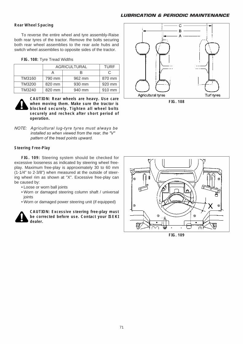
LUBRICATION & PERIODIC MAINTENANCE
71
Rear Wheel Spacing
To reverse the entire wheel and tyre assembly-Raiseboth rear tyres of the tractor. Remove the bolts securingboth rear wheel assemblies to the rear axle hubs andswitch wheel assemblies to opposite sides of the tractor.
FIG. 108: Tyre Tread Widths
CAUTION: Rear wheels are heavy. Use carewhen moving them. Make sure the tractor isblocked securely. Tighten all wheel boltssecurely and recheck after short period ofoperation.
NOTE: Agricultural lug-tyre tyres must always be installed so when viewed from the rear, the "V" pattern of the tread points upward.
Steering Free-Play
FIG. 109: Steering system should be checked forexcessive looseness as indicated by steering wheel free-play. Maximum free-play is approximately 30 to 60 mm(1-1/4" to 2-3/8") when measured at the outside of steer-ing wheel rim as shown at "X". Excessive free-play canbe caused by:
• Loose or worn ball joints• Worn or damaged steering column shaft / universal
joints• Worn or damaged power steering unit (if equipped)
CAUTION: Excessive steering free-play mustbe corrected before use. Contact your ISEKIdealer.
AGRICULTURAL TURFA B C
TM3160 790 mm 962 mm 870 mmTM3200 820 mm 930 mm 920 mmTM3240 820 mm 940 mm 910 mm
FIG. 108
FIG. 109
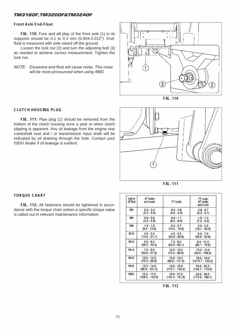
TM3160F,TM3200F&TM3240F
72
Front Axle End-Float
FIG. 110: Fore and aft play of the front axle (1) in itssupports should be 0.1 to 0.3 mm (0.004-0.012"). End-float is measured with axle raised off the ground.
Loosen the lock nut (2) and turn the adjusting bolt (3)as needed to achieve correct measurement. Tighten thelock nut.
NOTE: Excessive end-float will cause noise. This noise will be more pronounced when using 4WD.
CLUTCH HOUSING PLUG
FIG. 111: Pipe plug (1) should be removed from thebottom of the clutch housing once a year or when clutchslipping is apparent. Any oil leakage from the engine rearcrankshaft seal and / or transmission input shaft will beindicated by oil draining through the hole. Contact yourISEKI dealer if oil leakage is evident.
TORQUE CHART
FIG. 112: All fasteners should be tightened in accor-dance with the torque chart unless a specific torque valueis called out in relevant maintenance information.
FIG. 110
FIG. 112
FIG. 111
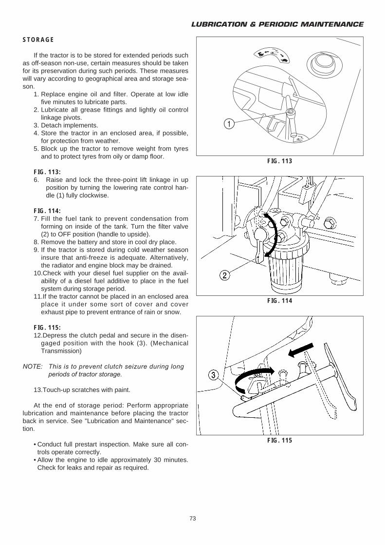
LUBRICATION & PERIODIC MAINTENANCE
73
STORAGE
If the tractor is to be stored for extended periods suchas off-season non-use, certain measures should be takenfor its preservation during such periods. These measureswill vary according to geographical area and storage sea-son.
1. Replace engine oil and filter. Operate at low idle five minutes to lubricate parts.
2. Lubricate all grease fittings and lightly oil control linkage pivots.
3. Detach implements.4. Store the tractor in an enclosed area, if possible,
for protection from weather.5. Block up the tractor to remove weight from tyres
and to protect tyres from oily or damp floor.
FIG. 113:6. Raise and lock the three-point lift linkage in up
position by turning the lowering rate control han-dle (1) fully clockwise.
FIG. 114:7. Fill the fuel tank to prevent condensation from
forming on inside of the tank. Turn the filter valve (2) to OFF position (handle to upside).
8. Remove the battery and store in cool dry place.9. If the tractor is stored during cold weather season
insure that anti-freeze is adequate. Alternatively, the radiator and engine block may be drained.
10.Check with your diesel fuel supplier on the avail-ability of a diesel fuel additive to place in the fuel system during storage period.
11.If the tractor cannot be placed in an enclosed area place it under some sort of cover and cover exhaust pipe to prevent entrance of rain or snow.
FIG. 115:12.Depress the clutch pedal and secure in the disen-
gaged position with the hook (3). (Mechanical Transmission)
NOTE: This is to prevent clutch seizure during long periods of tractor storage.
13.Touch-up scratches with paint.
At the end of storage period: Perform appropriatelubrication and maintenance before placing the tractorback in service. See "Lubrication and Maintenance" sec-tion.
• Conduct full prestart inspection. Make sure all con-trols operate correctly.
• Allow the engine to idle approximately 30 minutes. Check for leaks and repair as required.
FIG. 113
FIG. 114
FIG. 115
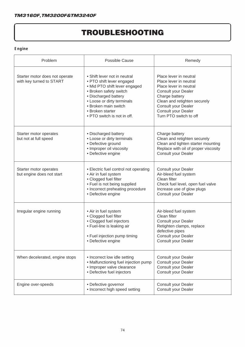
TM3160F,TM3200F&TM3240F
74
Engine
Problem Possible Cause Remedy
Starter motor does not operatewith key turned to START
• Shift lever not in neutral• PTO shift lever engaged• Mid PTO shift lever engaged• Broken safety switch• Discharged battery• Loose or dirty terminals• Broken main switch• Broken starter• PTO switch is not in off.
Place lever in neutralPlace lever in neutralPlace lever in neutralConsult your DealerCharge batteryClean and retighten securelyConsult your DealerConsult your DealerTurn PTO switch to off
Starter motor operatesbut not at full speed
• Discharged battery• Loose or dirty terminals• Defective ground• Improper oil viscosity• Defective engine
Charge batteryClean and retighten securelyClean and tighten starter mountingReplace with oil of proper viscosityConsult your Dealer
Starter motor operatesbut engine does not start
• Electric fuel control not operating• Air in fuel system• Clogged fuel filter• Fuel is not being supplied• Incorrect preheating procedure• Defective engine
Consult your DealerAir-bleed fuel systemClean filterCheck fuel level, open fuel valveIncrease use of glow plugsConsult your Dealer
Irregular engine running • Air in fuel system• Clogged fuel filter• Clogged fuel injectors• Fuel-line is leaking air
• Fuel injection pump timing• Defective engine
Air-bleed fuel systemClean filterConsult your DealerRetighten clamps, replacedefective pipesConsult your DealerConsult your Dealer
When decelerated, engine stops • Incorrect low idle setting• Malfunctioning fuel injection pump• Improper valve clearance• Defective fuel injectors
Consult your DealerConsult your DealerConsult your DealerConsult your Dealer
Engine over-speeds • Defective governor• Incorrect high speed setting
Consult your DealerConsult your Dealer
TROUBLESHOOTING
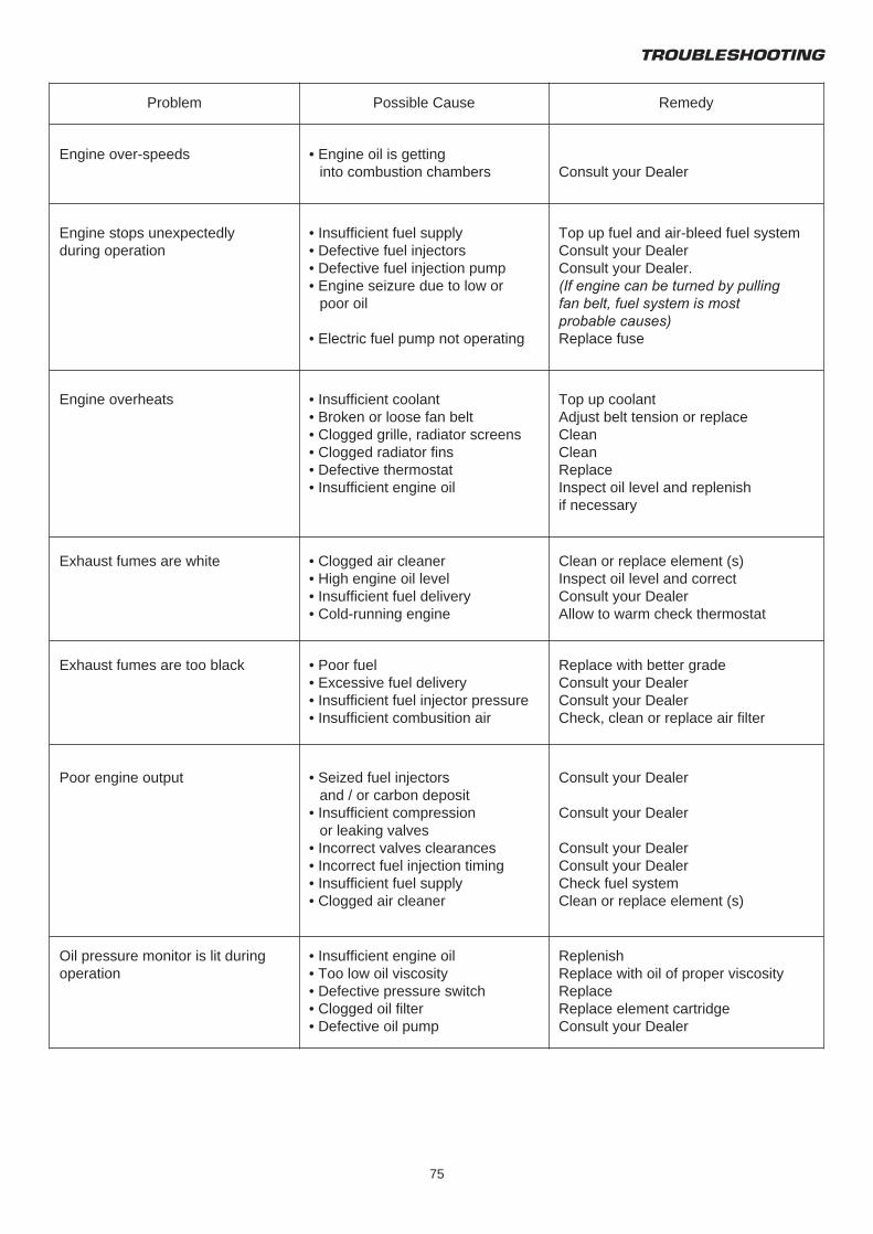
TROUBLESHOOTING
75
Problem Possible Cause Remedy
Engine over-speeds
Engine stops unexpectedlyduring operation
Engine overheats
Exhaust fumes are white
Exhaust fumes are too black
Poor engine output
Oil pressure monitor is lit duringoperation
• Engine oil is gettinginto combustion chambers
• Insufficient fuel supply• Defective fuel injectors• Defective fuel injection pump• Engine seizure due to low or
poor oil
• Electric fuel pump not operating
• Insufficient coolant• Broken or loose fan belt• Clogged grille, radiator screens• Clogged radiator fins• Defective thermostat• Insufficient engine oil
• Clogged air cleaner• High engine oil level• Insufficient fuel delivery• Cold-running engine
• Poor fuel• Excessive fuel delivery• Insufficient fuel injector pressure• Insufficient combusition air
• Seized fuel injectorsand / or carbon deposit
• Insufficient compressionor leaking valves
• Incorrect valves clearances• Incorrect fuel injection timing• Insufficient fuel supply• Clogged air cleaner
• Insufficient engine oil• Too low oil viscosity• Defective pressure switch• Clogged oil filter• Defective oil pump
Consult your Dealer
Top up fuel and air-bleed fuel systemConsult your DealerConsult your Dealer.(If engine can be turned by pullingfan belt, fuel system is mostprobable causes)Replace fuse
Top up coolantAdjust belt tension or replaceCleanCleanReplaceInspect oil level and replenishif necessary
Clean or replace element (s)Inspect oil level and correctConsult your DealerAllow to warm check thermostat
Replace with better gradeConsult your DealerConsult your DealerCheck, clean or replace air filter
Consult your Dealer
Consult your Dealer
Consult your DealerConsult your DealerCheck fuel systemClean or replace element (s)
ReplenishReplace with oil of proper viscosityReplaceReplace element cartridgeConsult your Dealer
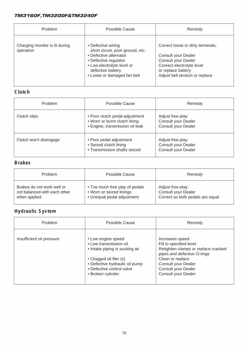
TM3160F,TM3200F&TM3240F
76
Problem Possible Cause Remedy
Charging monitor is lit duringoperation
• Defective wiringshort circuit, poor ground, etc.
• Defective alternator• Defective regulator• Low electrolyte level or
defective battery• Loose or damaged fan belt
Correct loose or dirty terminals,
Consult your DealerConsult your DealerCoreect electrolyte levelor replace batteryAdjust belt tension or replace
Problem Possible Cause Remedy
Clutch slips
Clutch won't disengage
• Poor clutch pedal adjustment• Worn or burnt clutch lining• Engine, transmission oil leak
• Poor pedal adjustment• Seized clutch lining• Transmission shafts seized
Adjust free-playConsult your DealerConsult your Dealer
Adjust free-playConsult your DealerConsult your Dealer
Problem Possible Cause Remedy
Brakes do not work well ornot balanced with each otherwhen applied
• Too much free play of pedals• Worn or seized linings• Unequal pedal adjustment
Adjust free-playConsult your DealerCorrect so both pedals are equal
Problem Possible Cause Remedy
Insufficient oil pressure • Low engine speed• Low transmission oil• Intake piping is sucking air
• Clogged oil filer (s)• Defective hydraulic oil pump• Defective control valve• Broken cylinder
Increases speedFill to specified levelRetighten clamps or replace crackedpipes and defective O-ringsClean or replaceConsult your DealerConsult your DealerConsult your Dealer
Clutch
Brakes
Hydraulic System
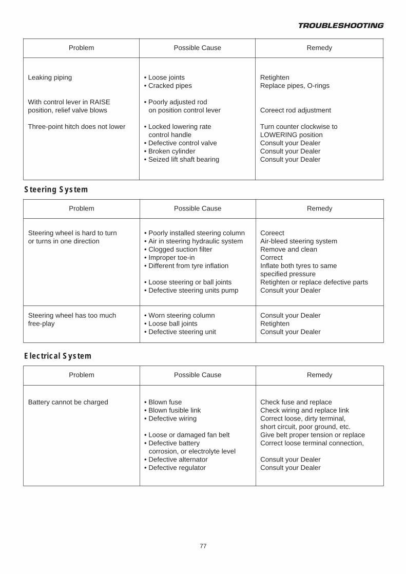
TROUBLESHOOTING
77
Problem Possible Cause Remedy
Leaking piping
With control lever in RAISEposition, relief valve blows
Three-point hitch does not lower
• Loose joints• Cracked pipes
• Poorly adjusted rodon position control lever
• Locked lowering ratecontrol handle
• Defective control valve• Broken cylinder• Seized lift shaft bearing
RetightenReplace pipes, O-rings
Coreect rod adjustment
Turn counter clockwise toLOWERING positionConsult your DealerConsult your DealerConsult your Dealer
Problem Possible Cause Remedy
Steering wheel is hard to turnor turns in one direction
Steering wheel has too muchfree-play
• Poorly installed steering column• Air in steering hydraulic system• Clogged suction filter• Improper toe-in• Different from tyre inflation
• Loose steering or ball joints• Defective steering units pump
• Worn steering column• Loose ball joints• Defective steering unit
CoreectAir-bleed steering systemRemove and cleanCorrectInflate both tyres to samespecified pressureRetighten or replace defective partsConsult your Dealer
Consult your DealerRetightenConsult your Dealer
Problem Possible Cause Remedy
Battery cannot be charged • Blown fuse• Blown fusible link• Defective wiring
• Loose or damaged fan belt• Defective battery
corrosion, or electrolyte level• Defective alternator• Defective regulator
Check fuse and replaceCheck wiring and replace linkCorrect loose, dirty terminal,short circuit, poor ground, etc.Give belt proper tension or replaceCorrect loose terminal connection,
Consult your DealerConsult your Dealer
Steering System
Electrical System

TM3160F,TM3200F&TM3240F
78
Problem Possible Cause Remedy
Head lamps are dim
Particular function will not operate
• Discharged battery
• Poor connections
• Burnt bulb (as applicable)• Blown fuse• Blown fusible, link• Poor contact
• Defective switch
Charge battery,check charging systemCheck ground points andterminals. Clean and tighten
ReplaceCheck fuse and replaceCheck wiring and replaceInspect ground points andterminals. Clean if necessaryReplace as required
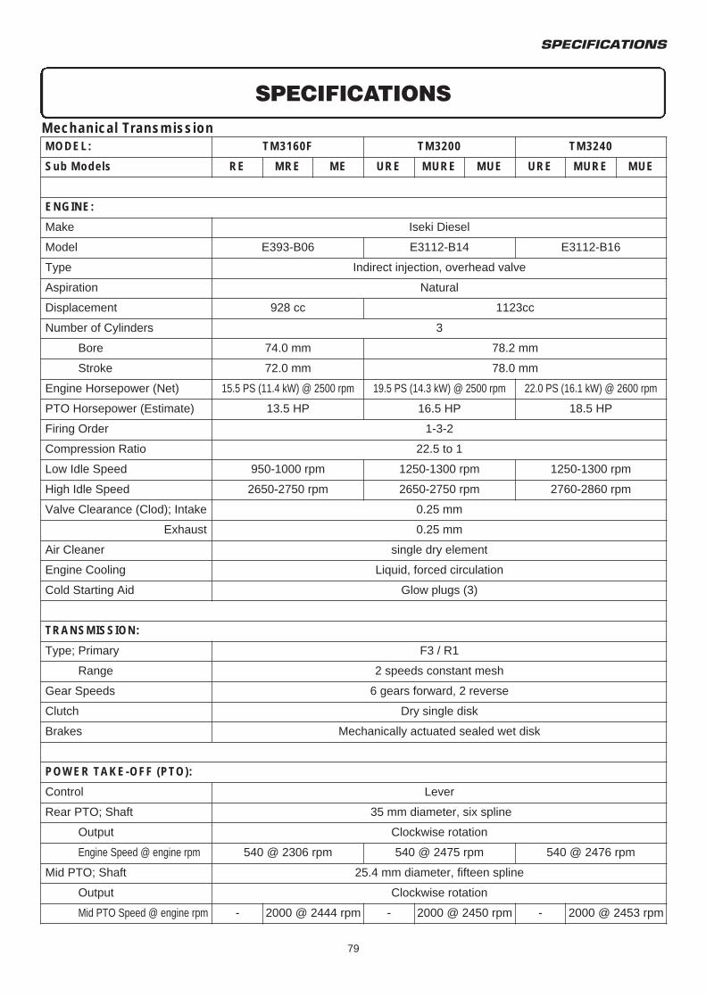
Mechanical Transmission
SPECIFICATIONS
79
SPECIFICATIONS
MODEL: TM3160F TM3200 TM3240
Sub Models RE MRE ME URE MURE MUE URE MURE MUE
ENGINE:
Make Iseki Diesel
Model E393-B06 E3112-B14 E3112-B16
Type Indirect injection, overhead valve
Aspiration Natural
Displacement 928 cc 1123cc
Number of Cylinders 3
Bore 74.0 mm 78.2 mm
Stroke 72.0 mm 78.0 mm
Engine Horsepower (Net) 15.5 PS (11.4 kW) @ 2500 rpm 19.5 PS (14.3 kW) @ 2500 rpm 22.0 PS (16.1 kW) @ 2600 rpm
PTO Horsepower (Estimate) 13.5 HP 16.5 HP 18.5 HP
Firing Order 1-3-2
Compression Ratio 22.5 to 1
Low Idle Speed 950-1000 rpm 1250-1300 rpm 1250-1300 rpm
High Idle Speed 2650-2750 rpm 2650-2750 rpm 2760-2860 rpm
Valve Clearance (Clod); Intake 0.25 mm
Exhaust 0.25 mm
Air Cleaner single dry element
Engine Cooling Liquid, forced circulation
Cold Starting Aid Glow plugs (3)
TRANSMISSION:
Type; Primary F3 / R1
Range 2 speeds constant mesh
Gear Speeds 6 gears forward, 2 reverse
Clutch Dry single disk
Brakes Mechanically actuated sealed wet disk
POWER TAKE-OFF (PTO):
Control
Rear PTO; Shaft
Lever
35 mm diameter, six spline
Output Clockwise rotation
Engine Speed @ engine rpm 540 @ 2306 rpm 540 @ 2475 rpm 540 @ 2476 rpm
Mid PTO; Shaft 25.4 mm diameter, fifteen spline
Output Clockwise rotation
Mid PTO Speed @ engine rpm - 2000 @ 2444 rpm - 2000 @ 2450 rpm - 2000 @ 2453 rpm
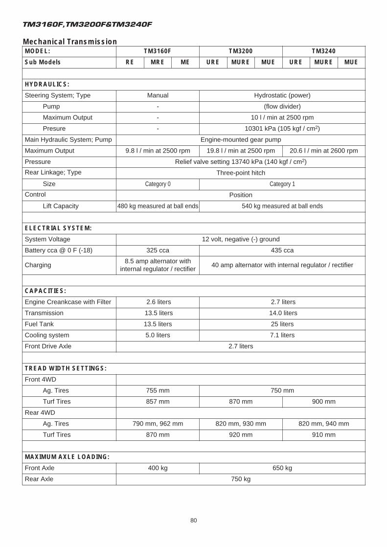
Mechanical Transmission
TM3160F,TM3200F&TM3240F
80
MODEL: TM3160F TM3200 TM3240
Sub Models RE MRE ME URE MURE MUE URE MURE MUE
HYDRAULICS:
Steering System; Type Manual Hydrostatic (power)
Pump - (flow divider)
Maximum Output - 10 l / min at 2500 rpm
Presure - 10301 kPa (105 kgf / cm2)
Main Hydraulic System; Pump Engine-mounted gear pump
Maximum Output 9.8 l / min at 2500 rpm 19.8 l / min at 2500 rpm 20.6 l / min at 2600 rpm
Pressure Relief valve setting 13740 kPa (140 kgf / cm2)
Rear Linkage; Type Three-point hitch
Size Category 0 Category 1
Control Position
Lift Capacity 480 kg measured at ball ends 540 kg measured at ball ends
ELECTRIAL SYSTEM:
System Voltage 12 volt, negative (-) ground
Battery cca @ 0 F (-18) 325 cca 435 cca
Charging8.5 amp alternator with
internal regulator / rectifier40 amp alternator with internal regulator / rectifier
CAPACITIES:
Engine Creankcase with Filter 2.6 liters 2.7 liters
Transmission 13.5 liters 14.0 liters
Fuel Tank 13.5 liters 25 liters
Cooling system 5.0 liters 7.1 liters
Front Drive Axle 2.7 liters
TREAD WIDTH SETTINGS:
Front 4WD
Ag. Tires
Turf Tires
Rear 4WD
Ag. Tires
Turf Tires
MAXIMUM AXLE LOADING:
Front Axle
Rear Axle
755 mm 750 mm
857 mm 870 mm 900 mm
790 mm, 962 mm 820 mm, 930 mm 820 mm, 940 mm
870 mm 920 mm 910 mm
400 kg 650 kg
750 kg
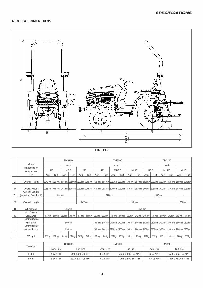
SPECIFICATIONS
81
GENERAL DIMENSIONS
FIG. 116
Tire sizeTM3160 TM3200 TM3240
Agri. Tire Turf Tire Agri. Tire Turf Tire Agri. Tire Turf Tire
Front 5-12 4PR 20 x 8.00 -10 4PR 5-12 4PR 20.5 x 8.00 -10 4PR 5-12 4PR 23 x 10.50 -12 4PR
Rear 8-16 4PR 212 / 80D -15 4PR 8-18 4PR 29 x 12.00-15 4PR 9.5-16 4PR 315 / 75 D -5 4PR
Model
Transmission
Sub-models
Tire
TM3160 TM3200 TM3240
mech. mech. mech.
RE MRE ME URE MURE MUE URE MURE MUE
Agri Turf Agri Turf Agri Turf Agri Turf Agri Turf Agri Turf Agri Turf Agri Turf Agri Turf
A Overall Height 2245 mm 2220 mm 2245 mm 2220 mm 1280 mm 1255 mm 2315 mm 2280 mm 2315 mm 2280 mm 1300 mm 1270 mm 2320 mm 2325 mm 2320 mm 2325 mm 1330 mm 1340 mm
B Overall Width 1068 mm 1096 mm 1068 mm 1096 mm 1280 mm 1255 mm 1070 mm 1210 mm 1070 mm 1210 mm 1070 mm 1210 mm 1070 mm 1230 mm 1070 mm 1230 mm 1070 mm 1230 mm
C1
C2
Overall Length
(including front hitch)
Overall Length
2585 mm
-
-
2485 mm
2860 mm
-
-
2760 mm
2860 mm
-
-
2760 mm
D Wheelbase 1345 mm 1520 mm
E
Min. Ground
Clearance 215 mm 190 mm 215 mm 190 mm 265 mm 240 mm 235 mm 200 mm 235 mm 200 mm 285 mm 245 mm 240 mm 245 mm 240 mm 245 mm 290 mm 295 mm
-
Turning radius
with brake 2000 mm 2400 mm 2600 mm 2400 mm 2600 mm 2400 mm 2600 mm 2400 mm 2600 mm 2400 mm 2600 mm 2400 mm 2600 mm
-
Turning radius
without brake 2300 mm 2700 mm 2900 mm 2700 mm 2900 mm 2700 mm 2600 mm 2400 mm 2600 mm 2400 mm 2600 mm 2400 mm 2600 mm
- Weight 600 kg 590 kg 605 kg 595 kg 570 kg 560 kg 655 kg 645 kg 660 kg 650 kg 630 kg 620 kg 670 kg 685 kg 675 kg 690 kg 645 kg 660 kg
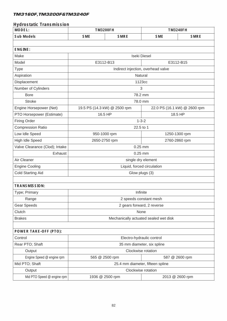
Hydrostatic Transmission
TM3160F,TM3200F&TM3240F
82
MODEL: TM3200FH TM3240FH
Sub Models SME SMRE SME SMRE
ENGINE:
Make Iseki Diesel
Model E3112-B13 E3112-B15
Type Indirect injection, overhead valve
Aspiration Natural
Displacement 1123cc
Number of Cylinders 3
Bore 78.2 mm
Stroke 78.0 mm
Engine Horsepower (Net) 19.5 PS (14.3 kW) @ 2500 rpm 22.0 PS (16.1 kW) @ 2600 rpm
PTO Horsepower (Estimate) 16.5 HP 18.5 HP
Firing Order 1-3-2
Compression Ratio 22.5 to 1
Low Idle Speed 950-1000 rpm 1250-1300 rpm
High Idle Speed 2650-2750 rpm 2760-2860 rpm
Valve Clearance (Clod); Intake 0.25 mm
Exhaust 0.25 mm
Air Cleaner single dry element
Engine Cooling Liquid, forced circulation
Cold Starting Aid Glow plugs (3)
TRANSMISSION:
Type; Primary Infinite
Range 2 speeds constant mesh
Gear Speeds 2 gears forward, 2 reverse
Clutch None
Brakes Mechanically actuated sealed wet disk
POWER TAKE-OFF (PTO):
Control
Rear PTO; Shaft
Electro-hydraulic control
35 mm diameter, six spline
Output Clockwise rotation
Engine Speed @ engine rpm 565 @ 2500 rpm 587 @ 2600 rpm
Mid PTO; Shaft 25.4 mm diameter, fifteen spline
Output Clockwise rotation
Mid PTO Speed @ engine rpm 1936 @ 2500 rpm 2013 @ 2600 rpm
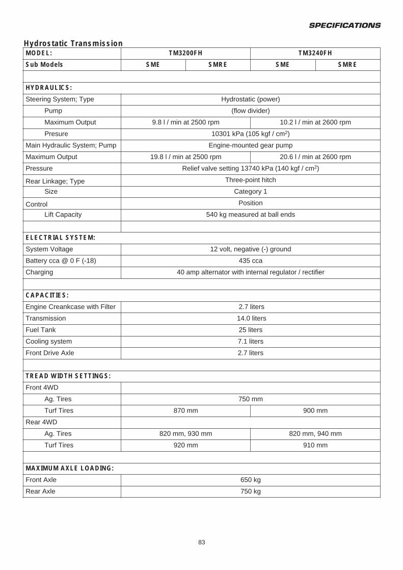
Hydrostatic Transmission
SPECIFICATIONS
83
MODEL: TM3200FH TM3240FH
Sub Models SME SMRE SME SMRE
HYDRAULICS:
Steering System; Type Hydrostatic (power)
Pump (flow divider)
Maximum Output 9.8 l / min at 2500 rpm 10.2 l / min at 2600 rpm
Presure 10301 kPa (105 kgf / cm2)
Main Hydraulic System; Pump Engine-mounted gear pump
Maximum Output 19.8 l / min at 2500 rpm 20.6 l / min at 2600 rpm
Pressure Relief valve setting 13740 kPa (140 kgf / cm2)
Rear Linkage; Type Three-point hitch
Size Category 1
Control Position
Lift Capacity 540 kg measured at ball ends
ELECTRIAL SYSTEM:
System Voltage 12 volt, negative (-) ground
Battery cca @ 0 F (-18) 435 cca
Charging 40 amp alternator with internal regulator / rectifier
CAPACITIES:
Engine Creankcase with Filter 2.7 liters
Transmission 14.0 liters
Fuel Tank 25 liters
Cooling system 7.1 liters
Front Drive Axle 2.7 liters
TREAD WIDTH SETTINGS:
Front 4WD
Ag. Tires
Turf Tires
Rear 4WD
Ag. Tires
Turf Tires
MAXIMUM AXLE LOADING:
Front Axle
Rear Axle
750 mm
870 mm 900 mm
820 mm, 930 mm 820 mm, 940 mm
920 mm 910 mm
650 kg
750 kg
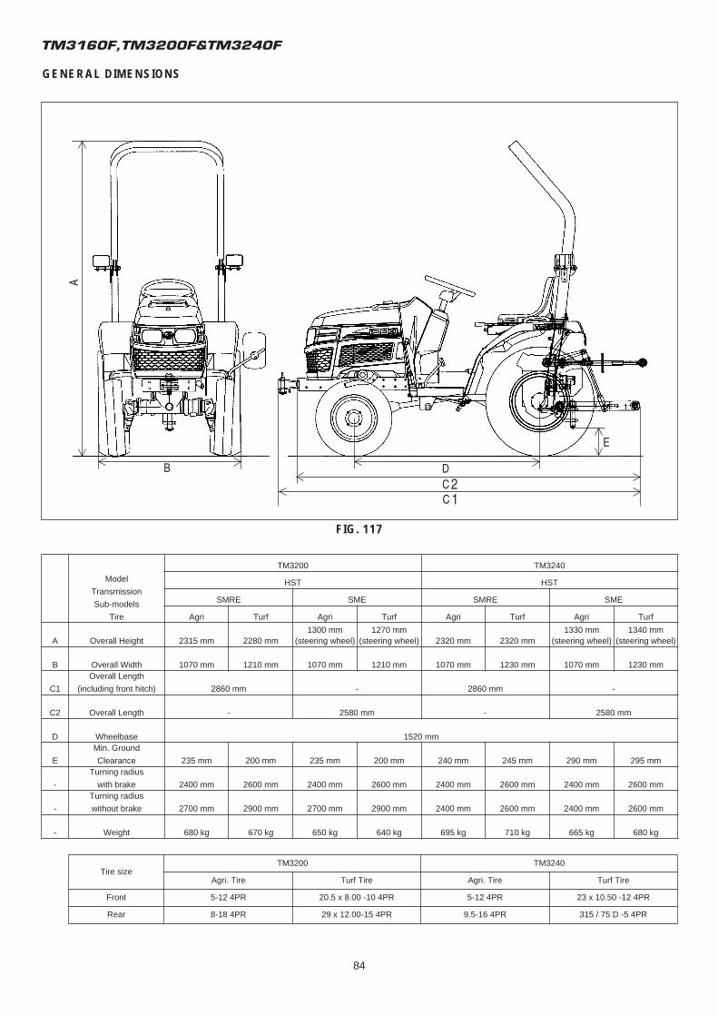
TM3160F,TM3200F&TM3240F
84
GENERAL DIMENSIONS
FIG. 117
Tire sizeTM3200 TM3240
Agri. Tire Turf Tire Agri. Tire Turf Tire
Front 5-12 4PR 20.5 x 8.00 -10 4PR 5-12 4PR 23 x 10.50 -12 4PR
Rear 8-18 4PR 29 x 12.00-15 4PR 9.5-16 4PR 315 / 75 D -5 4PR
Model
Transmission
Sub-models
Tire
TM3200 TM3240
HST HST
SMRE SME SMRE SME
Agri Turf Agri Turf Agri Turf Agri Turf
A Overall Height 2315 mm 2280 mm1300 mm
(steering wheel)1270 mm
(steering wheel) 2320 mm 2320 mm1330 mm
(steering wheel)1340 mm
(steering wheel)
B Overall Width 1070 mm 1210 mm 1070 mm 1210 mm 1070 mm 1230 mm 1070 mm 1230 mm
C1
C2
Overall Length
(including front hitch)
Overall Length
2860 mm
-
-
2580 mm
2860 mm
-
-
2580 mm
D Wheelbase 1520 mm
E
Min. Ground
Clearance 235 mm 200 mm 235 mm 200 mm 240 mm 245 mm 290 mm 295 mm
-
Turning radius
with brake 2400 mm 2600 mm 2400 mm 2600 mm 2400 mm 2600 mm 2400 mm 2600 mm
-
Turning radius
without brake 2700 mm 2900 mm 2700 mm 2900 mm 2400 mm 2600 mm 2400 mm 2600 mm
- Weight 680 kg 670 kg 650 kg 640 kg 695 kg 710 kg 665 kg 680 kg
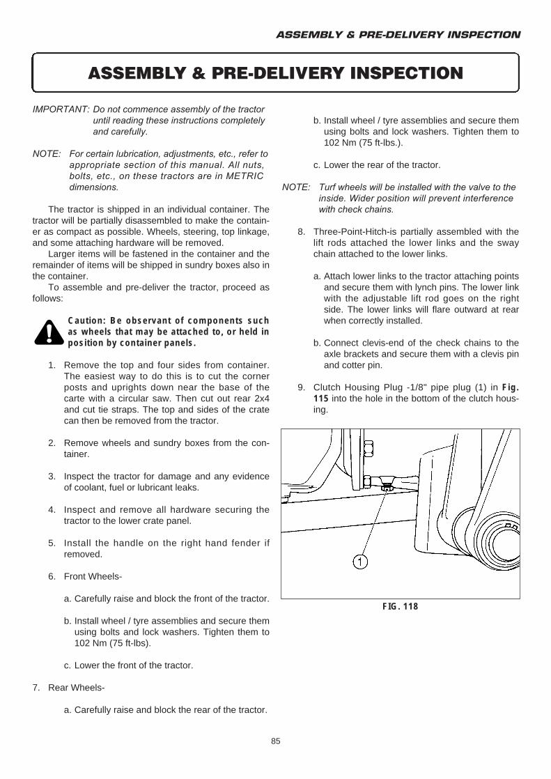
b. Install wheel / tyre assemblies and secure themusing bolts and lock washers. Tighten them to 102 Nm (75 ft-lbs.).
c. Lower the rear of the tractor.
NOTE: Turf wheels will be installed with the valve to the inside. Wider position will prevent interference with check chains.
8. Three-Point-Hitch-is partially assembled with the lift rods attached the lower links and the sway chain attached to the lower links.
a. Attach lower links to the tractor attaching points and secure them with lynch pins. The lower link with the adjustable lift rod goes on the right side. The lower links will flare outward at rear when correctly installed.
b. Connect clevis-end of the check chains to the axle brackets and secure them with a clevis pin and cotter pin.
9. Clutch Housing Plug -1/8" pipe plug (1) in Fig. 115 into the hole in the bottom of the clutch hous-ing.
ASSEMBLY & PRE-DELIVERY INSPECTION
85
IMPORTANT: Do not commence assembly of the tractor until reading these instructions completely and carefully.
NOTE: For certain lubrication, adjustments, etc., refer to appropriate section of this manual. All nuts, bolts, etc., on these tractors are in METRIC dimensions.
The tractor is shipped in an individual container. Thetractor will be partially disassembled to make the contain-er as compact as possible. Wheels, steering, top linkage,and some attaching hardware will be removed.
Larger items will be fastened in the container and theremainder of items will be shipped in sundry boxes also inthe container.
To assemble and pre-deliver the tractor, proceed asfollows:
Caution: Be observant of components suchas wheels that may be attached to, or held inposition by container panels.
1. Remove the top and four sides from container. The easiest way to do this is to cut the corner posts and uprights down near the base of the carte with a circular saw. Then cut out rear 2x4 and cut tie straps. The top and sides of the crate can then be removed from the tractor.
2. Remove wheels and sundry boxes from the con-tainer.
3. Inspect the tractor for damage and any evidence of coolant, fuel or lubricant leaks.
4. Inspect and remove all hardware securing the tractor to the lower crate panel.
5. Install the handle on the right hand fender if removed.
6. Front Wheels-
a. Carefully raise and block the front of the tractor.
b. Install wheel / tyre assemblies and secure them using bolts and lock washers. Tighten them to 102 Nm (75 ft-lbs).
c. Lower the front of the tractor.
7. Rear Wheels-
a. Carefully raise and block the rear of the tractor.
ASSEMBLY & PRE-DELIVERY INSPECTION
FIG. 118
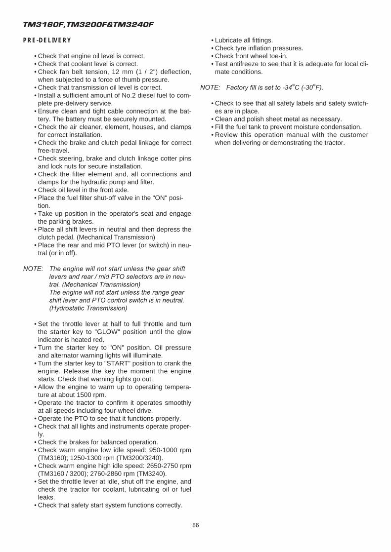
TM3160F,TM3200F&TM3240F
86
• Lubricate all fittings.• Check tyre inflation pressures.• Check front wheel toe-in.• Test antifreeze to see that it is adequate for local cli-
mate conditions.
NOTE: Factory fill is set to -34°C (-30°F).
• Check to see that all safety labels and safety switch-es are in place.
• Clean and polish sheet metal as necessary.• Fill the fuel tank to prevent moisture condensation.• Review this operation manual with the customer
when delivering or demonstrating the tractor.
PRE-DELIVERY
• Check that engine oil level is correct.• Check that coolant level is correct.• Check fan belt tension, 12 mm (1 / 2") deflection,
when subjected to a force of thumb pressure.• Check that transmission oil level is correct.• Install a sufficient amount of No.2 diesel fuel to com-
plete pre-delivery service.• Ensure clean and tight cable connection at the bat-
tery. The battery must be securely mounted.• Check the air cleaner, element, houses, and clamps
for correct installation.• Check the brake and clutch pedal linkage for correct
free-travel.• Check steering, brake and clutch linkage cotter pins
and lock nuts for secure installation.• Check the filter element and, all connections and
clamps for the hydraulic pump and filter.• Check oil level in the front axle.• Place the fuel filter shut-off valve in the "ON" posi-
tion.• Take up position in the operator's seat and engage
the parking brakes.• Place all shift levers in neutral and then depress the
clutch pedal. (Mechanical Transmission)• Place the rear and mid PTO lever (or switch) in neu-
tral (or in off).
NOTE: The engine will not start unless the gear shift levers and rear / mid PTO selectors are in neu-tral. (Mechanical Transmission)The engine will not start unless the range gear shift lever and PTO control switch is in neutral. (Hydrostatic Transmission)
• Set the throttle lever at half to full throttle and turn the starter key to "GLOW" position until the glow indicator is heated red.
• Turn the starter key to "ON" position. Oil pressure and alternator warning lights will illuminate.
• Turn the starter key to "START" position to crank the engine. Release the key the moment the engine starts. Check that warning lights go out.
• Allow the engine to warm up to operating tempera-ture at about 1500 rpm.
• Operate the tractor to confirm it operates smoothly at all speeds including four-wheel drive.
• Operate the PTO to see that it functions properly.• Check that all lights and instruments operate proper-
ly.• Check the brakes for balanced operation.• Check warm engine low idle speed: 950-1000 rpm
(TM3160); 1250-1300 rpm (TM3200/3240).• Check warm engine high idle speed: 2650-2750 rpm
(TM3160 / 3200); 2760-2860 rpm (TM3240).• Set the throttle lever at idle, shut off the engine, and
check the tractor for coolant, lubricating oil or fuel leaks.
• Check that safety start system functions correctly.
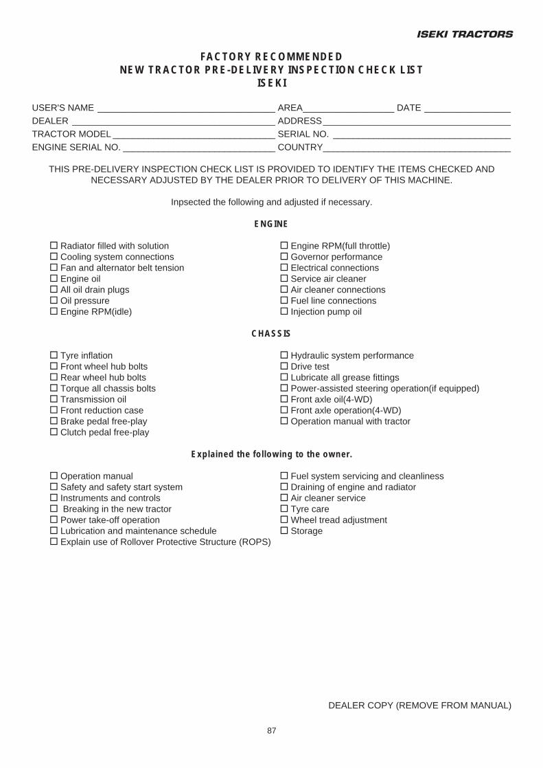
ISEKI TRACTORS
87
FACTORY RECOMMENDEDNEW TRACTOR PRE-DELIVERY INSPECTION CHECK LIST
ISEKI
USER'S NAME ___________________________________ AREA__________________ DATE _________________DEALER ________________________________________ ADDRESS_____________________________________TRACTOR MODEL ________________________________ SERIAL NO. ___________________________________ENGINE SERIAL NO. ______________________________ COUNTRY_____________________________________
THIS PRE-DELIVERY INSPECTION CHECK LIST IS PROVIDED TO IDENTIFY THE ITEMS CHECKED ANDNECESSARY ADJUSTED BY THE DEALER PRIOR TO DELIVERY OF THIS MACHINE.
Inpsected the following and adjusted if necessary.
ENGINE
T Radiator filled with solution T Engine RPM(full throttle)T Cooling system connections T Governor performanceT Fan and alternator belt tension T Electrical connectionsT Engine oil T Service air cleanerT All oil drain plugs T Air cleaner connectionsT Oil pressure T Fuel line connectionsT Engine RPM(idle) T Injection pump oil
CHASSIS
T Tyre inflation T Hydraulic system performanceT Front wheel hub bolts T Drive testT Rear wheel hub bolts T Lubricate all grease fittingsT Torque all chassis bolts T Power-assisted steering operation(if equipped)T Transmission oil T Front axle oil(4-WD)T Front reduction case T Front axle operation(4-WD)T Brake pedal free-play T Operation manual with tractorT Clutch pedal free-play
Explained the following to the owner.
T Operation manual T Fuel system servicing and cleanlinessT Safety and safety start system T Draining of engine and radiatorT Instruments and controls T Air cleaner serviceT Breaking in the new tractor T Tyre careT Power take-off operation T Wheel tread adjustmentT Lubrication and maintenance schedule T StorageT Explain use of Rollover Protective Structure (ROPS)
DEALER COPY (REMOVE FROM MANUAL)

TM3160F,TM3200F&TM3240F
88

ISEKI TRACTORS
89
FACTORY RECOMMENDEDNEW TRACTOR PRE-DELIVERY INSPECTION CHECK LIST
ISEKI
USER'S NAME ___________________________________ AREA__________________ DATE _________________DEALER ________________________________________ ADDRESS_____________________________________TRACTOR MODEL ________________________________ SERIAL NO. ___________________________________ENGINE SERIAL NO. ______________________________ COUNTRY_____________________________________
THIS PRE-DELIVERY INSPECTION CHECK LIST IS PROVIDED TO IDENTIFY THE ITEMS CHECKED ANDNECESSARY ADJUSTED BY THE DEALER PRIOR TO DELIVERY OF THIS MACHINE.
Inpsected the following and adjusted if necessary.
ENGINE
T Radiator filled with solution T Engine RPM(full throttle)T Cooling system connections T Governor performanceT Fan and alternator belt tension T Electrical connectionsT Engine oil T Service air cleanerT All oil drain plugs T Air cleaner connectionsT Oil pressure T Fuel line connectionsT Engine RPM(idle) T Injection pump oil
CHASSIS
T Tyre inflation T Hydraulic system performanceT Front wheel hub bolts T Drive testT Rear wheel hub bolts T Lubricate all grease fittingsT Torque all chassis bolts T Power-assisted steering operation(if equipped)T Transmission oil T Front axle oil(4-WD)T Front reduction case T Front axle operation(4-WD)T Brake pedal free-play T Operation manual with tractorT Clutch pedal free-play
Explained the following to the owner.
T Operation manual T Fuel system servicing and cleanlinessT Safety and safety start system T Draining of engine and radiatorT Instruments and controls T Air cleaner serviceT Breaking in the new tractor T Tyre careT Power take-off operation T Wheel tread adjustmentT Lubrication and maintenance schedule T StorageT Explain use of Rollover Protective Structure (ROPS)
DEALER COPY (REMOVE FROM MANUAL)

TM3160F,TM3200F&TM3240F
90
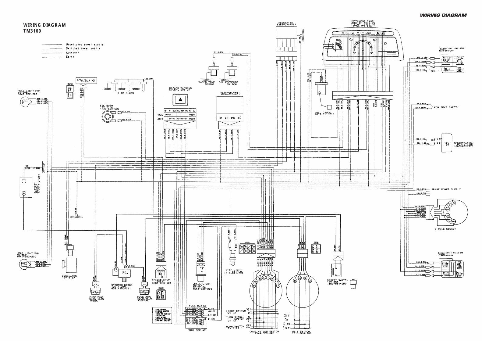
WIRING DIAGRAMWIRING DIAGRAM
WIRING DIAGRAMTM3160
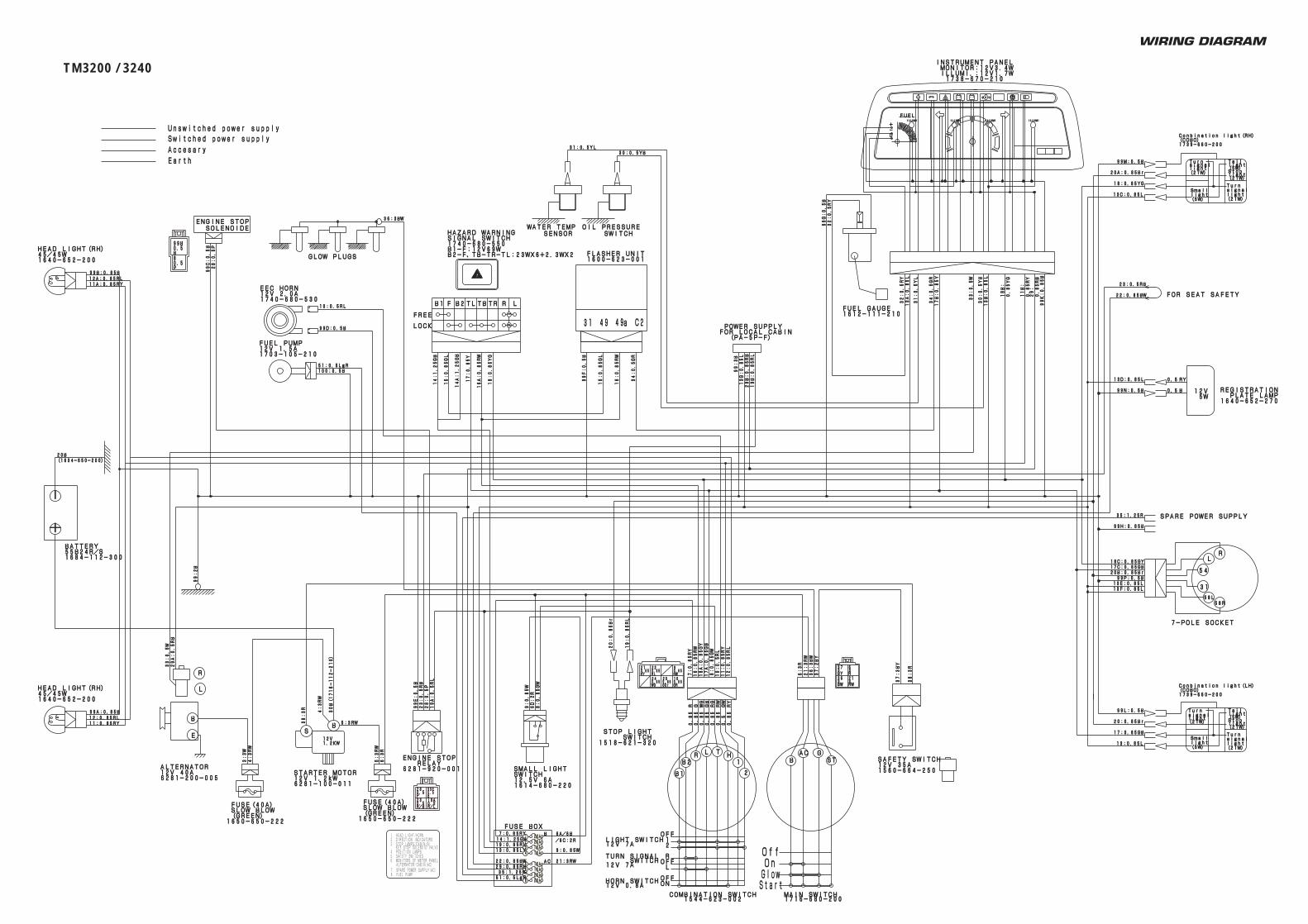
WIRING DIAGRAM
88 20A20A
(PA-5P-F) (PA-5P-F)FOR LOCAL CABINFOR LOCAL CABIN POWER SUPPLY POWER SUPPLY
1703-105-2101703-105-21012V 1.5A12V 1.5AFUEL PUMPFUEL PUMP
99P:0.5B99P:0.5B
99N:0.5B99N:0.5B
99M:0.5B99M:0.5B
99L:0.5B99L:0.5B
99K:0.85B
99K:0.85B
99G:0.5B
99G:0.5B
99F:0.5B
99F:0.5B
99E:0.5B
99E:0.5B
99D:0.5B99D:0.5B
99C:0.5B
99C:0.5B
99:2B
99:2B
(1634-650-200)(1634-650-200)20B20B
30:0.5YB30:0.5YB31:0.5YL31:0.5YL
100:0.5B100:0.5B51:0.5LgR51:0.5LgR
10:0.5RL10:0.5RL38:3R
38:3R
36:3BW36:3BW
37:2BY
37:2BY
36:3BW
36:3BW
99H:0.85B99H:0.85B
35:1.25R35:1.25R
28:0.5P
28:0.5P
28:0.5P
28:0.5P
99:3B
99:3B
13G:0.85L
13G:0.85L
29B:0.85RB
29B:0.85RB
19B:0.85RL
19B:0.85RL
34:0.5GR
34:0.5GR
34:0.5GR
34:0.5GR
32:0.5RY
32:0.5RY
31:0.5YL
31:0.5YL
33:0.5W
33:0.5W
0.85RY
0.85RY
11B:
11B:
13B:0.85L
13B:0.85L
30:0.5YB
30:0.5YB
32:0.5RY
32:0.5RY
29:
29:
0.85RB
0.85RB
38:3R
38:3R33:0.5W
33:0.5W
29A:0.5RB
29A:0.5RB
23:0.5RB
23:0.5RB
23:0.5RB23:0.5RB
22:0.85BW22:0.85BW
37:3BY
37:3BY
35:1.25R35:1.25R51:0.5LgR51:0.5LgR
29:0.85RB29:0.85RB22:0.85BW22:0.85BW 21:3RW21:3RW
21:3RW
21:3RW
20A:0.85Br20A:0.85Br
20B:0.85Br20B:0.85Br
20:0.85Br20:0.85Br
20:0.85Br
20:0.85Br
19A:0.5RL
19A:0.5RL
19:0.85RL
19:0.85RL
19:0.85RL19:0.85RL
18C:0.85GY18C:0.85GY17C:0.85GB17C:0.85GB
0.85YG
0.85YG
18B:
18B:
17B:0.85Y
17B:0.85Y
18:0.85YG18:0.85YG
17:0.85GB17:0.85GB
18:0.85YG
18:0.85YG
17:0.85Y
17:0.85Y
17A:0.85GB
17A:0.85GB
18A:0.85GY
18A:0.85GY
12:0.85RL
12:0.85RL
11:0.85RY
11:0.85RY
10:0.5RL
10:0.5RL
6:3R
6:3R
6:3R
6:3R
5:3RW
5:3RW
5:3RW5:3RW
4:3RW
4:3RW
4:3RW
4:3RW
3:3W
3:3W
30B(1716-112-210)
30B(1716-112-210)
16:0.85RW
16:0.85RW
16A:0.85RW
16A:0.85RW
16:0.85RW
16:0.85RW
15:0.85GL
15:0.85GL
15:0.85GL
15:0.85GL
14A:1.25GB
14A:1.25GB
14:1.25GB
14:1.25GB
14:1.25GB14:1.25GB
13F:0.85L13F:0.85L13E:0.85L13E:0.85L
13D:0.85L13D:0.85L
13C:0.85L13C:0.85L
13A:0.85L
13A:0.85L
13:0.85L13:0.85L
13:0.85LY13:0.85LY
7:0.85RY7:0.85RY
9:0.85W9:0.85W
/6C:2R/6C:2R6A/6B6A/6B
9:0.85W
9:0.85W
8:0.85GW
8:0.85GW
8:0.85GW
8:0.85GW
8. FUEL PUMP
5. SAFETY SWITCHES
KEY STOP SOLENOID VALVE3. STOP LAMPS/CABIN(B)
ALTERNATOR/CABIN(AC)6. MONITORS OF METER PANEL
7. SPARE POWER SUPPLY(AC)
4. POSITION LAMPS
2. DIRECTION INDICATORS1. HEAD LIGHT/HORN
6D:2R
6D:2R
7:0.85RY
7:0.85RY
99A:0.85B99A:0.85B12:0.85RL12:0.85RL11:0.85RY11:0.85RY
99B:0.85B99B:0.85B12A:0.85RL12A:0.85RL11A:0.85RY11A:0.85RY
FUSE BOXFUSE BOX
SPARE POWER SUPPLYSPARE POWER SUPPLY
77 20A20A
ACAC
66 10A10A55 10A10A
44 10A10A10A10A33
22 20A20A11 20A20A
1612-111-2101612-111-210FUEL GAUGEFUEL GAUGE
7-POLE SOCKET 7-POLE SOCKET
58R58R58L58L
3131
5454
LLRR
1518-621-3201518-621-320 SWITCH SWITCH STOP LIGHT STOP LIGHT
ILLUMIILLUMIILLUMIILLUMI ILLUMIILLUMI ILLUMIILLUMI
1738-670-210 1738-670-210 ILLUMI.:12V1.7W ILLUMI.:12V1.7W MONITOR:12V3.4W MONITOR:12V3.4WINSTRUMENT PANELINSTRUMENT PANEL
FUELFUEL
UU--++
B2-F、TB-TR-TL:23WX6+2.3WX2B2-F、TB-TR-TL:23WX6+2.3WX2B1-F:12V69WB1-F:12V69W1740-680-5501740-680-550SIGNAL SWITCHSIGNAL SWITCHHAZARD WARNINGHAZARD WARNING
FF LLRRTRTRTBTBTLTLB2B2B1B1
LOCKLOCK
FREEFREE
1640-652-2701640-652-270 PLATE LAMP PLATE LAMPREGISTRATIONREGISTRATION
5W 5W12V12V0.50.5 BB
0.50.5 RYRY
1739-660-2001739-660-200(COBO)(COBO)Conbination light(RH)Conbination light(RH)
(21W)(21W)lightlightStopStop(5W)(5W)lightlightTailTail
(21W)(21W)lightlightsignalsignalTurnTurn
(5W)(5W)lightlightSmallSmall
(21W)(21W)lightlightsignalsignalTurnTurn
1739-660-2001739-660-200(COBO)(COBO)Conbination light(LH)Conbination light(LH)
(21W)(21W)lightlightStopStop(5W)(5W)lightlightTailTail
(21W)(21W)lightlightsignalsignalTurnTurn
(5W)(5W)lightlightSmallSmall
(21W)(21W)lightlightsignalsignalTurnTurn
1614-680-2201614-680-22012.5V 6A12.5V 6ASWITCHSWITCHSMALL LIGHTSMALL LIGHT
1600-623-0011600-623-001FLASHER UNITFLASHER UNIT
aa3131 C2C24949 4949
FOR SEAT SAFETYFOR SEAT SAFETY
12V 7A12V 7A SWITCH SWITCHTURN SIGNALTURN SIGNAL
0.5 GW
0.5 GW
12V 0.8A12V 0.8AHORN SWITCHHORN SWITCH
12V 7A12V 7ALIGHT SWITCHLIGHT SWITCH
1544-623-002 1544-623-002COMBINATION SWITCHCOMBINATION SWITCH
0.85 RW
0.85 RW
ONONOFFOFF
HH11
OFFOFF
2 2
R ROFFOFF L L
1 1
0.85 R
0.85 R
B2B2
0.85 G
0.85 G
0.85 RG
0.85 RG
LL
0.85 GB
0.85 GB
0.85 WG
0.85 WG
TTRR
22B1B1
0.85 RY
0.85 RY
1740-680-5301740-680-53012V 2.0A12V 2.0AEEC HORNEEC HORN
1640-652-2001640-652-20045/45W45/45WHEAD LIGHT(RH)HEAD LIGHT(RH)
1640-652-2001640-652-20045/45W45/45WHEAD LIGHT(RH)HEAD LIGHT(RH)
1560-664-2501560-664-25012V 35A12V 35ASAFETY SWITCHSAFETY SWITCH
6281-920-0016281-920-001 RELAY RELAYENGINE STOPENGINE STOP
WATER TEMPWATER TEMPSENSORSENSOR SWITCHSWITCH
OIL PRESSUREOIL PRESSURE SOLENOIDE SOLENOIDEENGINE STOPENGINE STOP
6281-100-0116281-100-01112V 1.2kW12V 1.2kWSTARTER MOTORSTARTER MOTOR
1.2KW1.2KW12V12V
BBSS
Unswitched power supplyUnswitched power supplySwitched power supplySwitched power supply
EarthEarthAccesaryAccesary
BB
1650-650-2221650-650-222 (GREEN) (GREEN) SLOW BLOW SLOW BLOW FUSE(40A) FUSE(40A)
GLOW PLUGSGLOW PLUGS
1684-112-3001684-112-30055B24R/S55B24R/SBATTERYBATTERY
--++
6281-200-0056281-200-00512V 40A12V 40AALTERNATORALTERNATOR
RR
LL
EE
BB
1650-650-2221650-650-222 (GREEN) (GREEN) SLOW BLOW SLOW BLOW FUSE(40A) FUSE(40A)
1716-680-2001716-680-200MAIN SWITCH MAIN SWITCH
STSTBB
StartStart
OnOnOffOff
GlowGlow
GGACAC
BYBY333737
BWBW333636
RWRW332121RR3366
GRGR
10102323
WGWG
2424RWRW
99
RLRLRYRY
GOrGOr0.850.85 0.850.85 0.850.85
0.850.850.850.85 0.850.852121 2222
R/LR/L0.50.519A19ABB0.50.599E99E
PP0.50.52828
R/BR/B0.50.52323
PP0.50.588BB0.50.599B99B
TM3200 / 3240
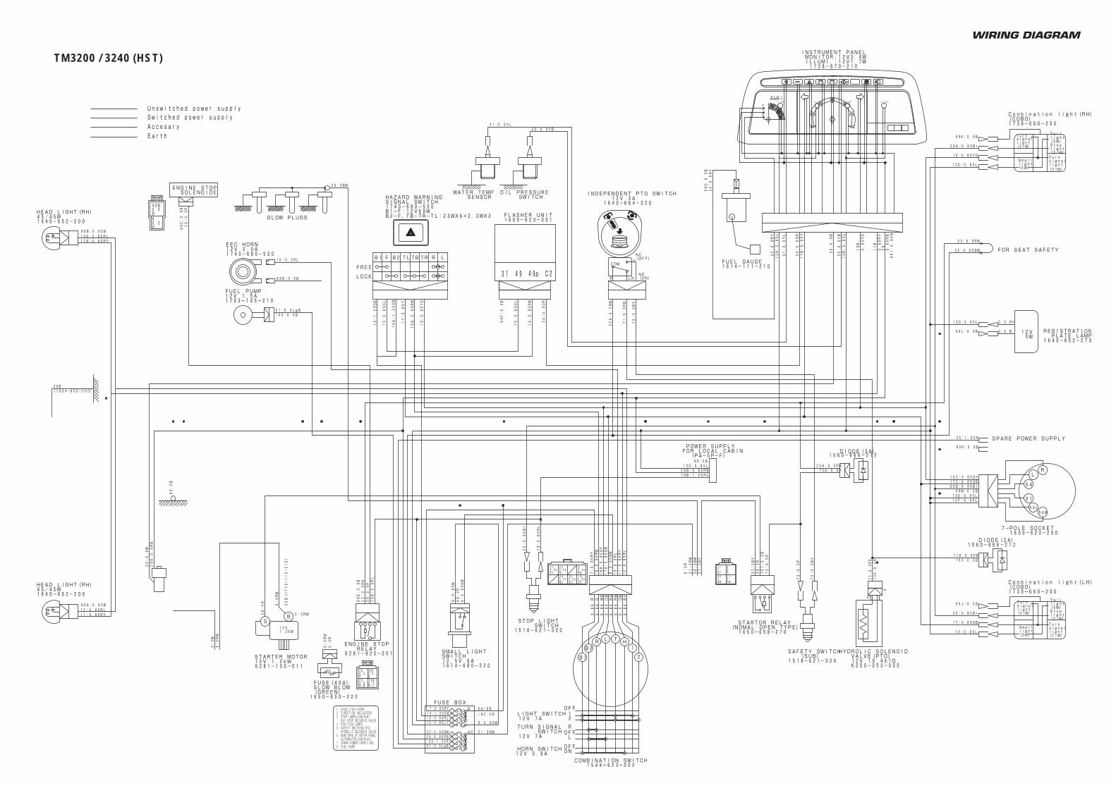
WIRING DIAGRAM
TM3200 / 3240 (HST)

TM3160TM3200TM3240
Overseas Business Department3-14, Nishi-Nippori, 5-chome, Arakawa-ku,Tokyo 116-8541, JapanPhone: (03) 5604-7658Fax: (03) 5604-7703
OM-TM3160/-EN-100312-01-300
Printed in Japan