Embed Size (px)
Citation preview
Models of Computation: FSM Model
Reading:L. Lavagno, A.S. Vincentelli and E. Sentovich, “Models of computation for Embedded System
Design”

Mahapatra-Texas A&M 2
Our Design Approach
• Start design process before hw-sw partitioning• Sequence of steps are vital
– system specification unbiased to implementation• describe system behavior at high level
– Initial functional design– verification– mapping to target architecture
• Thus, function-architecture codesign is key approach

Mahapatra-Texas A&M 3
Proposed design strategy
BehaviorialLibraryCaptureBehavior
Verifybehavior
ArchitectureLibraries
Verifyarchitecture
BehavioralLibrary
Map behaviorto Architecture
Verifyperformance
Refine HW/SWmicro-architect
Link to HW/SWimplementation
Link to micro-arch verification
PerformanceBack Annotation
Capturebehavior
Capture Architecture
Functional Level
MappingLevel
• Taken from Ref. Of reading assignment.
ArchitectureLevel

Mahapatra-Texas A&M 4
Design conception to design description
• At functional level, behavior of a system to be implemented is selected and analyzed against a set of specifications– Specifications vs.. behavior?
• Specs:I/O relation, set of constraints, system goals• behavior: algorithm to realize the function
-Specs: algorithm itself! (another view)
• Purists view: Algorithm is the result of implementation decision
Mahapatra-Texas A&M 5
Examples
• Example1: Let f(x) = 0 is a system to be implemented.
It is a design decision to use either Newton-Raphson or Gauss-SeidelS relaxation algorithm!
• Example2: MPEG Encoder design
Spec: Encoding of compressed stream of data.
Any implementation that creates it from the stream is correct. Here the design decision is already there.
Mahapatra-Texas A&M 6
Algorithm Design and Analysis
• Algorithm development: Key aspect of system design at functional level
• Little work has been done on selection of algorithm based on specifications
• Requires strong correctness properties in critical operations
• Algorithm analysis is more general concept than simulation
• Important to decide on mathematical model for designer that will support algorithm analysis

Mahapatra-Texas A&M 7
Algorithm Implementation
• Need of intermediate step: transform an algorithm to a set of tractable functional components
• The functional components are to be formally defined to capture the algorithm’s properties
• MoC is key answer to the above!• Selection of MoC is to be done carefully. (FSM,
DF, DES, Comm Seq. Process)

Mahapatra-Texas A&M 8
MoCsBasic Concepts
• MoC is composed of a description mechanism (syntax) and rules for computation of behavior given the syntax (semantics)
• It is chosen for its suitability: compactness, ability to synthesize, optimize the behavior of implementation
• Most MoCs Permit distributed system of description ( a collection of communicating modules), and gives rules of computation of each module (function), and how they communicate.
Mahapatra-Texas A&M 9
MoC Primitives
• Functions: combination of Boolean functions and synchronous state machines
• Communications: queues, buffers, and schedulers

Mahapatra-Texas A&M 10
Finite State Machine (FSM)

Mahapatra-Texas A&M 11

Mahapatra-Texas A&M 12

Mahapatra-Texas A&M 13
FSM
• Finite‐State Machine (FSM)
-A way to describe desired behavior of
Sequential circuit
–Akin to Boolean equations for• Combinational behavior
–List states, and transitions among states

14
Capturing Sequential Circuit Behavior as FSM
• Toggle switch example:• List states, and transitions among
states– Example: Toggle x every clock
cycle– Two states: “Lo” (x=0), and “Hi”
(x=1)– Transition from Lo to Hi, or Hi to
Lo, on rising clock edge (clk^)– Arrow points to initial state (when
circuit first starts)
Lo Hi Lo Hi Lo Hi Lo Hi
cycle 1 cycle 2 cycle 3 cycle 4clk
Lo LoHi Histate
x
Outputs:
Outputs: x
HiLo
x=0 x=1
clk^
clk^
aLo Hi
Lo Hi
or
Depicting multi-bit or other info in a timing diagram
15
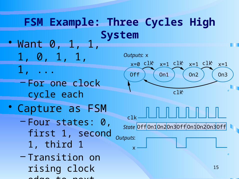
FSM Example: Three Cycles High System• Want 0, 1, 1, 1, 0, 1, 1,
1, ...– For one clock cycle
each
• Capture as FSM– Four states: 0, first 1,
second 1, third 1– Transition on rising
clock edge to next state
Off OffOn1On1On2 On2On3 On3Off
clk
x
State
Outputs:
Outputs: x
On1Off On2 On3
clk^
clk^
clk^x=1x=1x=0 x=1clk^
a
a

16
Three-Cycles High System with Button Input
• Four states• Wait in “Off” while b is 0
(b’*clk^) • When b is 1 (b*clk^),
transition to On1– Sets x=1– Next two clock edges,
transition to On2, then On3
• So x=1 for three cycles after button pressed
Off OffOn1Off Off Off On2On3Off
clk
State
Outputs:
Inputs:
x
b
Inputs: b Outputs: x
On2On1 On3
Off
clk^
clk^
x=1x=1x=1
x=0
clk^
b'*clk^
b*clk^

17
FSM Simplification: Rising Clock Edges Implicit
• Every edge ANDed with rising clock edge
• What if we wanted a transition without a rising edge
• We don’t consider such asynchronous FSMs – less common, and advanced topic
• Only consider synchronous FSMs – rising edge on every transition
Note: Transition with no associated condition thus transistions to next state on next clock cycle
On2On1 On3
Off
x=1x=1x=1
x=0
b’
b
Inputs: b; Outputs: x
On2On1 On3
Off
x=1x=1x=1
x=0
b’
clk̂
clk̂
^clk
*clk̂
*clk̂b
Inputs: b; Outputs: x
a
18
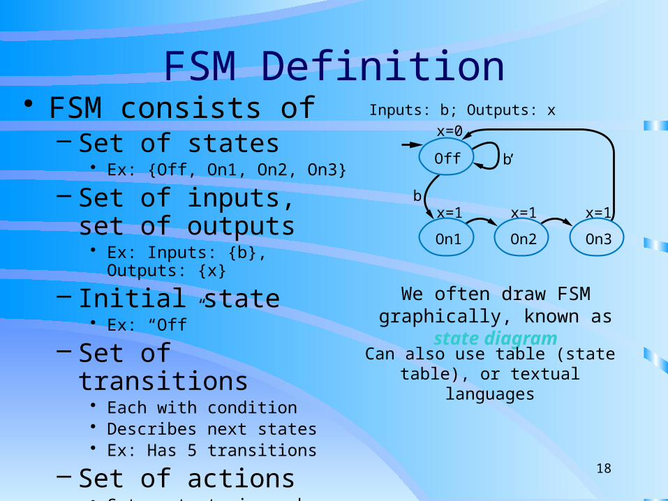
FSM Definition• FSM consists of
– Set of states• Ex: {Off, On1, On2, On3}
– Set of inputs, set of outputs
• Ex: Inputs: {b}, Outputs: {x}
– Initial state• Ex: “Off”
– Set of transitions• Each with condition• Describes next states• Ex: Has 5 transitions
– Set of actions• Sets outputs in each state• Ex: x=0, x=1, x=1, and x=1
Inputs: b; Outputs: x
On2On1 On3
Off
x=1x=1x=1
x=0
b’
b
We often draw FSM graphically, known as state diagram
Can also use table (state table), or textual languages

Mahapatra-Texas A&M 19
Modeling & Testing FSM
• Example of “Three Cycle High Laser Controller”
• Impl. the FSM in Verilog (High level IP)• Test using Verilog Testbench for functional
verification• Use of tools to create FSM and generate
Verilog Module
Mahapatra-Texas A&M 20
Assignment 1(practice problem)
“Three Cycle High Laser Controller” • Use Fizzim tool editor to create FSM from a given
specification. (manual process)• Use Fizzim to generate high-level IP written in
Verilog HDL.• Write testbench to verify functionality of the
module. Use ModelSim for verification.• Ref. Laser Controller Tutorial.

Mahapatra-Texas A&M 21
Assignment 1 (Things to do)
• Consider Interrupt Handler (IH) problem.– Ref: Tutorial on Interrupt Handler
• Specify the requirements/steps at high level• Create FSM, and generate Verilog IH-IP
module using Fizzim tools.• Verify IH-IP module using ModelSim.
– Modelsim.com student version free

Mahapatra-Texas A&M 22
Administration
• Group of two students with ECE and CS backgrounds
• Credits after successful demonstration.• You may have choice to pick up another
controller problem but with advanced notice to the instructor.
• Will show the valid results during demonstration.

Mahapatra-Texas A&M 23
Last slide
• Questions?