Embed Size (px)
Citation preview
Models:
KG10V08T-6CGS and KG10V08T-6DGS Turbocharged
Propane, Liquefied Petroleum Gas (LPG)
Natural Gas (NG) Fueled
Engine
TP-7172 9/20
Operation
2 TP-7172 9/20
WARNING: This product can expose you to chemicals, including carbon monoxide and benzene, which are known to the State of California to cause cancer and birth defects or other reproductive harm. For more information go to www.P65warnings.ca.gov
Product Identification Information
Product identification numbers determine service parts. Record the product identification numbers in the spaces below
immediately after unpacking the products so that the numbers are readily available for future reference.
Engine Identification
Record the product identification information from the engine nameplate.
Model Designation: __________________________
Serial Number: __________________________
Purchase Date
Upon purchase of your Kohler equipment, record the purchase date for reference when communicating with your authorized
Kohler distributor/dealer.
TP-7172 9/20 3
Table of Contents
Safety Precautions and Instructions ........................................................................................................................................ 5 Introduction .............................................................................................................................................................................. 11 Service Assistance................................................................................................................................................................... 12 Section 1. Components and Maintenance Locations ........................................................................................... 17
1.1 Engine Side Views ................................................................................................................................................. 17 1.2 Top and Rear Views ............................................................................................................................................... 18 1.3 Manufacturer and engine identification data ........................................................................................................... 19
Section 2. Operation ................................................................................................................................................ 21 2.1 Introduction ............................................................................................................................................................ 21 2.2 Fuel System ........................................................................................................................................................... 21
2.2.1 Components ............................................................................................................................................. 21 2.2.2 Fuel Specifications ................................................................................................................................... 27 2.2.3 Before Starting ......................................................................................................................................... 28 2.2.4 Starting..................................................................................................................................................... 29 2.2.5 Cold Weather Starting .............................................................................................................................. 30 2.2.6 Monitoring Engine Operation ................................................................................................................... 31 2.2.7 Stopping ................................................................................................................................................... 31
Section 3. Maintenance ........................................................................................................................................... 33 3.1 Introduction ............................................................................................................................................................ 33 3.2 Safety Precautions and Instructions ....................................................................................................................... 33 3.3 Fluid Specifications ................................................................................................................................................ 35
3.3.1 Oil Recommendations .............................................................................................................................. 35 3.3.2 Coolant Recommendations ...................................................................................................................... 35
3.4 Periodic Maintenance Schedule ............................................................................................................................. 36 3.5 Engine .................................................................................................................................................................... 37
3.5.1 Check Engine Oil ..................................................................................................................................... 37 3.5.2 Change Engine Oil and Oil Filter .............................................................................................................. 38 3.5.3 Check and Clean the Air Filter ................................................................................................................. 40 3.5.4 Replace the Air Filter ............................................................................................................................... 40 3.5.5 Check, Adjust and Replace the Spark Plugs............................................................................................ 41 3.5.6 Ignition Timing .......................................................................................................................................... 43
3.6 Electrical System .................................................................................................................................................... 43 3.6.1 Check Battery and Connections ............................................................................................................... 43 3.6.2 Check and Adjust the Drive Belt .............................................................................................................. 44 3.6.3 Replace the Drive Belt ............................................................................................................................. 46 3.6.4 Check Wiring and Electrical Connections ................................................................................................ 48
3.7 Cooling System ...................................................................................................................................................... 49 3.7.1 Check Coolant Level and Condition ......................................................................................................... 50 3.7.2 Check Hoses and Clamps........................................................................................................................ 51 3.7.3 Draining and Replacing the Coolant ........................................................................................................ 51
3.8 Fuel System ........................................................................................................................................................... 52 3.8.1 Check Fuel Supply Pipe and Connections ............................................................................................... 52 3.8.2 Check Fuel Level (LPG only) ................................................................................................................... 52
Section 4. Troubleshooting ..................................................................................................................................... 53 4.1 Introduction ............................................................................................................................................................ 53 4.2 Troubleshooting ..................................................................................................................................................... 53
Section 5. Storage.................................................................................................................................................... 55 5.1 Preparation ............................................................................................................................................................. 55 5.2 Short-Term Storage (Less than 30 Days) ............................................................................................................... 55 5.3 Long-Term Storage (More than 30 Days) ............................................................................................................... 56
4 TP-7172 9/20
5.4 Maintenance while in Storage ................................................................................................................................ 56 5.5 Removal from Storage ........................................................................................................................................... 56
Section 6. Specifications ......................................................................................................................................... 57 6.1 Engine Specifications ............................................................................................................................................. 57 6.2 Main Components Specifications ........................................................................................................................... 58 6.3 Adjustment Specifications ...................................................................................................................................... 58 6.4 Torque Specifications ............................................................................................................................................. 58 6.5 Standard Torque Specifications ............................................................................................................................. 59
TP-7172 9/20 5
Safety Precautions and Instructions
Read and follow all safety precautions and instructions. SAVE THESE INSTRUCTIONS.
DANGER
DANGER indicates a hazardous situation which, if not avoided, will result in death or serious injury.
WARNING
WARNING indicates a hazardous situation which, if not avoided, could result in death or serious injury.
CAUTION
CAUTION indicates a hazardous situation which, if not avoided, could result in minor or moderate injury.
NOTICE
NOTICE is used to address practices not related to physical injury.
Note:
A Note is used to inform you of important installation, operation, or maintenance information.
Accidental Starting
WARNING Accidental starting. Can cause severe injury or death.
Disconnect the battery cables before working on the engine. Remove the negative (–) lead first when disconnecting the battery. Reconnect the negative (–) lead last when reconnecting the battery.
Disabling the engine. Accidental starting can cause severe injury or death. Before working on the engine or connected
equipment, disable the engine as follows: 1) Disconnect the ignition coil. 2) Remove the battery cables, negative (–) lead first. Reconnect the negative (–) lead last when reconnecting the battery. Follow these precautions to prevent the accidental starting of the engine.
6 TP-7172 9/20
Battery
WARNING Sulfuric acid in batteries. Can cause severe injury or death.
Wear protective goggles and clothing. Battery acid may cause blindness and burn skin.
Battery electrolyte is a diluted sulfuric acid. Battery acid can cause severe injury or death. Battery acid can cause
blindness and burn skin. Always wear splashproof safety goggles, rubber gloves, and boots when servicing the battery. Do not open a sealed battery or mutilate the battery case. If battery acid splashes in the eyes or on the skin, immediately flush the affected area for 15 minutes with large quantities of clean water. Seek immediate medical aid in the case of eye contact. Never add acid to a battery after placing the battery in service, as this may result in hazardous spattering of battery acid.
Battery acid cleanup. Battery acid can cause severe injury or death. Battery acid is electrically conductive and corrosive.
Add 500 g (1 lb.) of bicarbonate of soda (baking soda) to a container with 4 L (1 gal.) of water and mix the neutralizing solution. Pour the neutralizing solution on the spilled battery acid and continue to add the neutralizing solution to the spilled battery acid until all evidence of a chemical reaction (foaming) has ceased. Flush the resulting liquid with water and dry the area.
Battery gases. Explosion can cause severe injury or death. Battery gases can cause an explosion. Do not smoke or permit
flames or sparks to occur near a battery at any time, particularly when it is charging. Do not dispose of a battery in a fire. To prevent burns and sparks that could cause an explosion, avoid touching the battery terminals with tools or other metal objects. Remove all jewelry before servicing the equipment. Discharge static electricity from your body before touching batteries by first touching a grounded metal surface away from the battery. To avoid sparks, do not disturb the battery charger connections while the battery is charging. Always turn the battery charger off before disconnecting the battery connections. Ventilate the compartments containing batteries to prevent accumulation of explosive gases.
Battery short circuits. Explosion can cause severe injury or death. Short circuits can cause bodily injury and/or equipment
damage. Disconnect the battery before maintenance. Remove all jewelry before servicing the equipment. Use tools with insulated handles. Remove the negative (–) lead first when disconnecting the battery. Reconnect the negative (–) lead last when reconnecting the battery. Never connect the negative (–) battery cable to the positive (+) connection terminal of the starter solenoid. Do not test the battery condition by shorting the terminals together.
Engine Backfire/Flash Fire
WARNING Risk of fire. Can cause severe injury or death.
Do not smoke or permit flames or sparks near fuels or the fuel system.
Servicing the fuel system. A flash fire can cause severe injury or death. Do not smoke or permit flames or sparks near the
fuel mixer, fuel line, fuel filter, or other potential sources of fuel vapors. When removing the fuel line or fuel system be aware that liquid propane can cause frostbite on contact.
Servicing the air cleaner. A sudden backfire can cause severe injury or death. Do not operate the engine with the air
cleaner/silencer removed.
Combustible materials. A fire can cause severe injury or death. Engine fuels and fuel vapors are flammable and explosive.
Handle these materials carefully to minimize the risk of fire or explosion. Equip the compartment or nearby area with a fully charged fire extinguisher. Select a fire extinguisher rated ABC or BC for electrical fires or as recommended by the local fire code or an authorized agency. Train all personnel on fire extinguisher operation and fire prevention procedures.
TP-7172 9/20 7
Engine Fluids and Chemical Products
WARNING Handling caustic engine fluids and chemical products. Can cause severe chemical burns, nausea, fainting, or death.
Most chemicals such as used engine oil, antifreeze/coolant, rustproofing agent, inhibiting oil, degreasing agent, spray paint, and adhesives are hazardous to health. Read and follow the user information found on the packaging. Avoid inhalation and skin contact. Use only in well-ventilated areas and use a protective mask when spraying. Store engine fluids and chemical products in a locked cabinet. Contact your local recycling center for disposal information and locations.
Fire-damaged or burned O-rings may cause the formation of hydrofluoric acid. Contact with hydrofluoric acid may cause severe skin irritation and chemical burns. O-rings and other fluoroelastomer seals exposed to fire or temperatures
above 316°C (600°F) (i.e., during welding) may decompose forming hydrofluoric acid. Avoid inhalation or skin contact. Do not incinerate O-rings. Dispose of O-ring waste material in a responsible manner.
Used engine oil. Contact with used engine oil may cause severe skin irritation. Repeated and prolonged skin exposure may have other health risks. Used engine oil is a suspected carcinogen. Avoid contact with skin. Thoroughly wash your hands
and nails with soap and water shortly after handling used engine oil. Wash or dispose of clothing or rags containing used engine oil. Dispose of used engine oil in a responsible manner. Contact your local recycling center for disposal information and locations.
Exhaust System
WARNING Carbon monoxide. Can cause severe nausea, fainting, or death.
The exhaust system must be leakproof and routinely inspected.
Carbon monoxide symptoms. Carbon monoxide can cause severe nausea, fainting, or death. Carbon monoxide is a
poisonous gas present in exhaust gases. Carbon monoxide is an odorless, colorless, tasteless, nonirritating gas that can cause death if inhaled for even a short time. Carbon monoxide poisoning symptoms include but are not limited to the following:
Light-headedness, dizziness
Physical fatigue, weakness in joints and muscles
Sleepiness, mental fatigue, inability to concentrate or speak clearly, blurred vision
Stomachache, vomiting, nausea
If experiencing any of these symptoms and carbon monoxide poisoning is possible, seek fresh air immediately and remain active. Do not sit, lie down, or fall asleep. Alert others to the possibility of carbon monoxide poisoning. Seek medical attention if the condition of affected persons does not improve within minutes of breathing fresh air.
Engine Operation. Carbon monoxide can cause severe nausea, fainting, or death. Engine exhaust gases contain
poisonous carbon monoxide. Carbon monoxide is an odorless, colorless, tasteless, nonirritating gas that can cause death if inhaled for even a short time. Avoid breathing exhaust fumes when working on or near the engine. Never operate the engine inside a building. Never operate the engine where exhaust gas could seep inside or be drawn into a potentially occupied building through windows, air intake vents, or other openings.
8 TP-7172 9/20
Fuel System
WARNING Explosive fuel vapors. Can cause severe injury or death.
Use extreme care when handling, storing, and using fuels.
The fuel system. Explosive fuel vapors can cause severe injury or death. Vaporized fuels are highly explosive. Use extreme
care when handling and storing fuels. Store fuels in a well-ventilated area away from spark-producing equipment and out of the reach of children. Never add fuel to the tank while the engine is running because spilled fuel may ignite on contact with hot parts or from sparks. Do not smoke or permit flames or sparks to occur near sources of spilled fuel or fuel vapors. Keep the fuel lines and connections tight and in good condition. Do not replace flexible fuel lines with rigid lines. Use flexible sections to avoid fuel line breakage caused by vibration. Do not operate the engine in the presence of fuel leaks, fuel accumulation, or sparks. Repair fuel systems before resuming engine operation.
Explosive fuel vapors can cause severe injury or death. Take additional precautions when using the following fuels:
Propane (LPG)—Adequate ventilation is mandatory. Because propane is heavier than air, install propane gas detectors low in
a room. Inspect the detectors per the manufacturer’s instructions.
Natural Gas—Adequate ventilation is mandatory. Because natural gas rises, install natural gas detectors high in a room. Inspect
the detectors per the manufacturer’s instructions.
WARNING Explosive fuel vapors. Can cause fires and severe burns.
If a gaseous odor is detected, ventilate the area and contact an authorized service technician.
Gas fuel leaks. Explosive fuel vapors can cause severe injury or death. Fuel leakage can cause an explosion. Check the
LPG vapor or natural gas fuel system for leakage by using a soap and water solution with the fuel system test pressurized to 6–8 ounces per square inch (10–14 inches water column). Do not use a soap solution containing either ammonia or chlorine because both prevent bubble formation. A successful test depends on the ability of the solution to bubble.
Hazardous Noise
CAUTION Hazardous noise. Can cause hearing loss.
Never operate the engine without a muffler or with a faulty exhaust system.
TP-7172 9/20 9
Hazardous Voltage/Moving Parts
WARNING Moving parts. Can cause severe injury or death.
Operate the engine only when all guards and electrical enclosures are in place. Stay away from moving parts while the engine is in operation.
Servicing the engine when it is operating. Exposed moving parts can cause severe injury or death. Keep hands, feet,
hair, clothing, and test leads away from the belts and pulleys when the engine is running. Replace guards, screens, and covers before operating the engine.
CAUTION Hazardous voltage. Electrical shock can cause injury.
Do not touch wires while the engine is running. Stop the engine and disconnect the battery leads, negative (-) lead first, before servicing the engine.
Heavy Equipment
WARNING Unbalanced weight. Improper lifting can cause severe injury or death and equipment damage.
Use adequate lifting capacity. Always maintain a safe distance from the equipment being lifted. Never stand under the equipment.
Hot Parts
WARNING Hot engine and exhaust system. Can cause severe injury or death.
Do not work on the engine until it cools.
Servicing the exhaust system. Hot parts can cause severe injury or death. Do not touch hot engine parts. The engine and
exhaust system components become extremely hot during operation.
WARNING Hot coolant and steam. Can cause severe injury or death.
Before removing the pressure cap, stop the engine and allow it to cool. Then loosen the pressure cap to relieve pressure.

10 TP-7172 9/20
TP-7172 9/20 11
Introduction
This manual provides operating and maintenance instructions for Kohler engines. Keep this manual with the equipment for future
reference. Refer to the service manual for detailed information on adjusting and servicing the engine.
Read this manual and carefully follow all procedures and safety precautions to ensure proper equipment operation and to avoid
bodily injury. Read and follow the Safety Precautions and Instructions section at the beginning of this manual. Keep this manual
with the equipment for future reference.
Information in this publication represents data available at the time of print. Kohler Co. reserves the right to change this
publication and the products represented without notice and without any obligation or liability whatsoever.
This engine operates on either propane, liquefied petroleum gas (LPG), or natural gas (NG), which are extremely flammable
and explosive. Installation and repair of LPG/NG systems must be performed only by qualified technicians. Read this manual
and carefully follow all procedures and safety precautions to ensure proper equipment operation and to avoid bodily injury.
Regular maintenance is necessary for safe and efficient operation. Inspect the engine often and perform required maintenance
at prescribed intervals. Service work must be performed by appropriately skilled and suitably trained maintenance personnel
who are familiar with engine diagnostics and repair.
Unless otherwise specified, all units of measurement are metric, followed by the United States customary unit equivalent.
Related Literature
The following chart identifies related literature available for the KG10V08T-6CGS and KG10V08T-6DGS engines. Only trained
and qualified personnel should install or service this engine.
Literature Type Part Number
Engine Service Manual TP-7176
Engine Service Manual, ECM Troubleshooting and Diagnostics TP-7097
Contact a Kohler authorized distributor/dealer for all maintenance, service, and engine parts. To find a Kohler authorized
distributor/dealer, visit KOHLERPower.com or call 1-800-544-2444 (U.S. and Canada).
12 TP-7172 9/20
Service Assistance
For professional advice and conscientious service, please
contact your nearest Kohler distributor or dealer.
Visit the Kohler Co. website at KOHLERPower.com.
Look at the labels and decals on your Kohler product or review the appropriate literature or documents included with the product.
Call toll free in the US and Canada 1-800-544-2444.
Outside the US and Canada, call the nearest regional office.
Headquarters Europe, Middle East, Africa (EMEA)
Kohler EMEA Headquarters Netherlands B.V. Kristallaan 1 4761 ZC Zevenbergen The Netherlands Phone: (31) 168 331630 Fax: (31) 168 331631
Asia Pacific
Kohler Asia Pacific Headquarters Singapore, Republic of Singapore Phone: (65) 6264-6422 Fax: (65) 6264-6455
China
North China Regional Office, Beijing Phone: (86) 10 6518 7950 (86) 10 6518 7951 (86) 10 6518 7952 Fax: (86) 10 6518 7955
East China Regional Office, Shanghai Phone: (86) 21 6288 0500 Fax: (86) 21 6288 0550
India, Bangladesh, Sri Lanka
India Regional Office Bangalore, India Phone: (91) 80 3366208 (91) 80 3366231 Fax: (91) 80 3315972
Japan, Korea
North Asia Regional Office Tokyo, Japan Phone: (813) 3440-4515 Fax: (813) 3440-2727
TP-7172 9/20 13
Stationary Emergency Standby Engine - Five Years Federal Exhaust Emissions Control Warranty Statement
YOUR WARRANTY RIGHTS AND OBLIGATIONS
The US Environmental Protection Agency (“US EPA”) and Kohler Co. are pleased to explain the exhaust emissions control
systems warranty on your 2020-2022 Stationary Emergency Standby engine. In the USA, Stationary Emergency Standby
engines and engine powered equipment must be designed, built and equipped to meet US EPA stringent anti-smog standards.
Kohler Co. must warrant the emissions control systems on your Stationary Emergency Standby engine for the period listed
below provided there has not been improper application, improper installation, abuse, neglect, improper maintenance, or
unapproved modifications of the stationary emergency standby engine.
Your exhaust emission control systems may include parts such as fuel systems, ignition system, turbocharger, intercooler, and
catalytic converters as further outlined below in Parts Covered by Warranty*.
MANUFACTURER’S WARRANTY COVERAGE:
The 1995 and later Stationary Emergency Standby engine exhaust emission control system is warranted for five years. If any
exhaust emission-related part on your Stationary Emergency Standby engine is defective, the part will be repaired or replaced
by Kohler Co.
OWNER’S WARRANTY RESPONSIBILITIES:
As the Stationary Emergency Standby engine ultimate purchaser, you are responsible for the performance of the required
maintenance listed in your owner’s manual. Kohler Co. recommends that you retain all receipts covering maintenance on your
Stationary Emergency Standby engine, but Kohler Co. cannot deny warranty solely for the lack of receipts. As the Stationary
Emergency Standby engine ultimate purchaser, you should however be aware that Kohler Co. may deny you warranty coverage
if your Stationary Emergency Standby engine or a part has failed due to improper application, improper installation, abuse,
neglect, improper maintenance or unapproved modifications as further outlined below in Limitations**.
You are responsible for presenting your Stationary Emergency Standby engine to an authorized Kohler Power Systems dealer
or distributor as soon as a problem exists. The warranty repairs should be completed in a reasonable amount of time, not to
exceed 30 days. If you have a question regarding your warranty coverage, you should contact an authorized Kohler Power
Systems dealer or distributor or contact the factory at 1-800-544-24444 or the website KOHLERPower.com.
14 TP-7172 9/20
GENERAL EMISSIONS WARRANTY COVERAGE
The warranty period begins on the date the engine or equipment is delivered to an ultimate purchaser. Kohler Co. warrants to
the ultimate purchaser and each subsequent purchaser that the Stationary Emergency Standby engine is:
designed, built, and equipped so as to conform with all applicable regulations adopted by US EPA; and free from defects in
materials and workmanship that cause the failure of a warranted part to be identical in all material respects to the part as
described in the engine manufacturer’s application for certification.
The warranty on emissions-related parts is as follows:
1. Any warranted part that is not scheduled for replacement as required maintenance in the owner’s manual supplied, is
warranted for the warranty period stated above. If any such part fails during the period of warranty coverage, the part
will be repaired or replaced by Kohler Co. at no charge to the ultimate purchaser. Any such part repaired or replaced
under the warranty will be warranted for the remaining warranty period.
2. Any warranted part that is scheduled only for regular inspection in the owner’s manual supplied, is warranted for the
warranty period stated above. Any such part repaired or replaced under warranty will be warranted for the remaining
warranty period.
3. Any warranted part that is scheduled for replacement as required maintenance in the owner’s manual supplied, is
warranted for the period of time prior to the first scheduled replacement point for that part. If the part fails prior to the
first scheduled replacement, the part will be repaired or replaced by Kohler Co. at no charge to the ultimate purchaser.
Any such part repaired or replaced under warranty will be warranted for the remainder of the period prior to the first
scheduled replacement point for the part.
4. Add-on or modified parts that are not exempted by the Air Resources Board may not be used. The use of any
nonexempt add-on or modified parts by the ultimate purchaser will be grounds for disallowing a warranty claim. The
manufacturer will not be liable to warrant failures of warranted parts caused by the use of a non-exempt add-on or
modified part.
TP-7172 9/20 15
PARTS COVERED BY WARRANTY*
Listed below are the parts (if equipped) covered by the Federal Warranty. Some parts listed below may require scheduled
maintenance and are warranted up to the first scheduled replacement point for that part.
Oxygen sensor
Intake manifold
Exhaust manifold
Catalytic muffler
Thermal reactor muffler
Fuel line, fuel line fittings and clamps
Spark advance module
Crankcase breather
Turbocharger
Intercooler
Wastegate control valve
Air Injection System
o Air pump or pulse valve assembly
o Control/distribution valve
o Distribution manifold
o Air hoses
o Vacuum lines
Ignition module(s) with high tension lead
Gaseous fuel regulator
Electronic control unit
Fuel injection system
Fuel metering valve
Air filter, fuel filter, and spark plugs (only to first replacement point)
16 TP-7172 9/20
Limitations**
This Emission Control Systems Warranty shall not cover any of the following:
1. Normal wear, routine tuneups, tuneup parts, adjustments, and periodic service.
2. Damage, including but not limited to damage caused by accidents, improper installation or handling, faulty repairs not
performed by an authorized Kohler service representative, improper storage, or acts of God.
3. Damage caused by operation at speeds, or with fuel, loads, conditions, modifications or installation contrary to
published specifications.
4. Damage caused by improper maintenance such as:
a. Failure to provide the specified type and sufficient quantity of lubricating oil.
b. Failure to keep the air intake and cooling fin areas clean.
c. Failure to service the air cleaner.
d. Failure to provide sufficient coolant and/or cooling air.
e. Failure to perform scheduled maintenance as prescribed in supplied manuals.
f. Failure to regularly exercise the engine under load (stationary applications only).
5. Original installation charges and startup costs.
6. Additional expenses for repairs performed after normal business hours, i.e. overtime or holiday labor rates.
7. Rental of equipment during the performance of warranty repairs.
8. Removal and replacement of non-Kohler-supplied options and equipment.
9. Non-Kohler replacement parts. Replacement of a failed Kohler part with a non-Kohler part voids the warranty on that
part.
10. Fuel injection pumps not repaired by an authorized Kohler service representative.
11. Non-Kohler-authorized repair shop labor without prior approval from Kohler Co. Warranty Department.
12. Engine fluids such as fuel, oil, or coolant/antifreeze.
13. Shop supplies such as adhesives, cleaning solvents, and rags.
14. Expenses incurred investigating performance complaints unless the problem is caused by defective Kohler materials
or workmanship.
TP-7172 9/20 17
Section 1. Components and Maintenance Locations
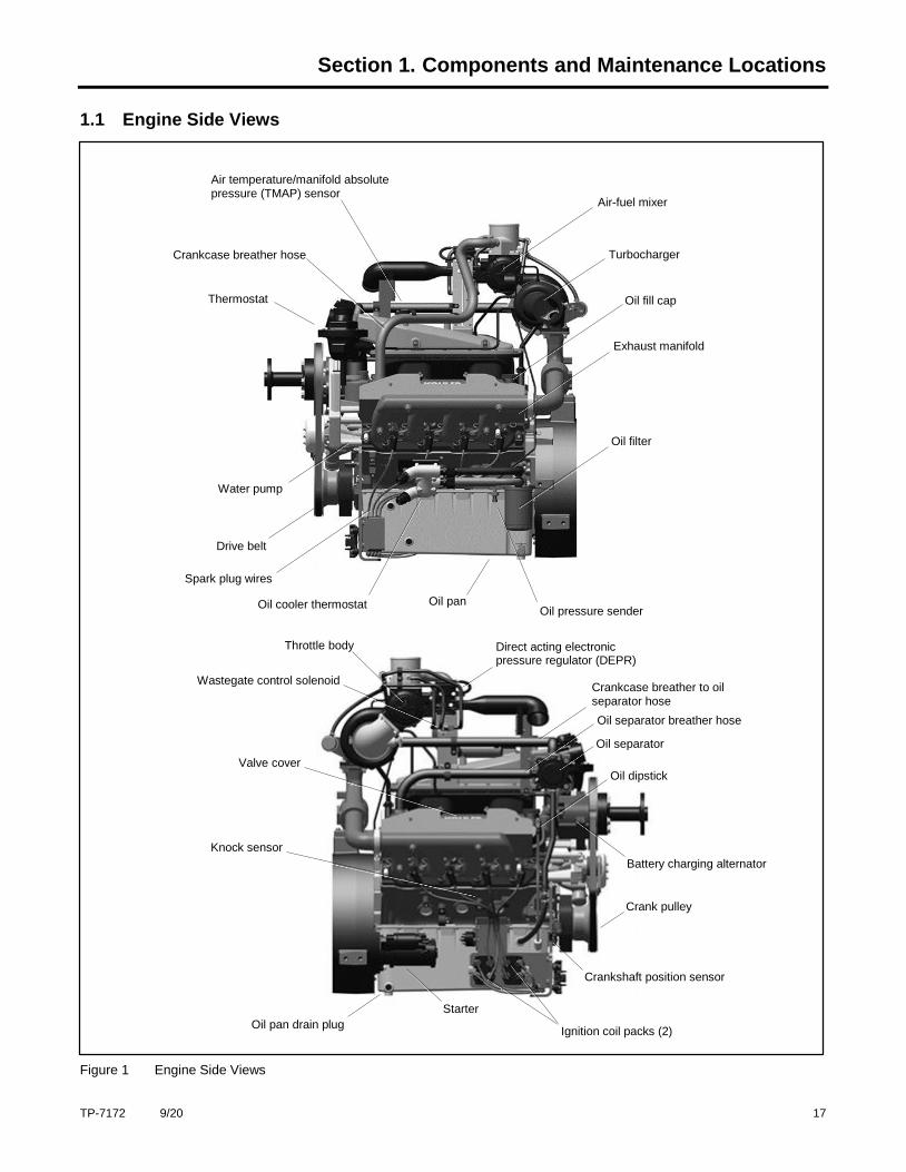
1.1 Engine Side Views
Figure 1 Engine Side Views
Oil cooler thermostat
Spark plug wires
Drive belt
Water pump
Oil pan
Thermostat
Crankcase breather hose
Air temperature/manifold absolute pressure (TMAP) sensor
Air-fuel mixer
Turbocharger
Oil fill cap
Exhaust manifold
Oil filter
Oil pressure sender
Direct acting electronic pressure regulator (DEPR)
Crankcase breather to oil separator hose
Oil separator breather hose
Oil separator
Oil dipstick
Battery charging alternator
Crank pulley
Crankshaft position sensor
Ignition coil packs (2)
Throttle body
Wastegate control solenoid
Valve cover
Knock sensor
Oil pan drain plug
Starter
18 TP-7172 9/20
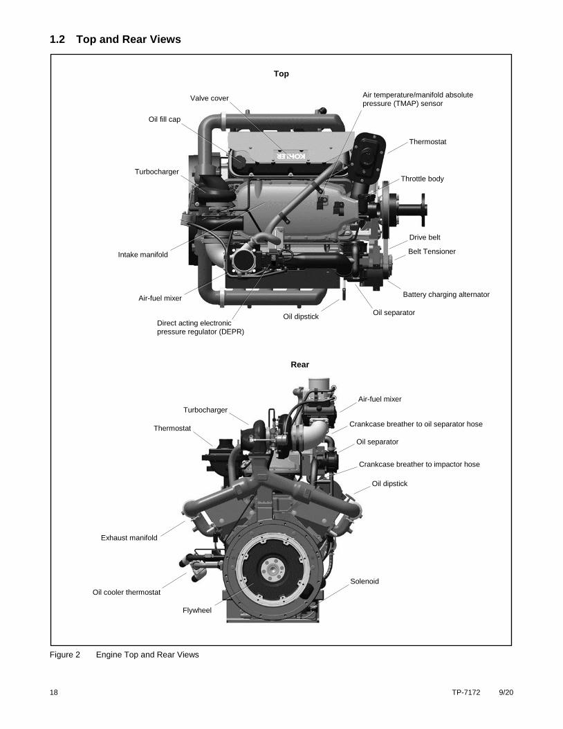
1.2 Top and Rear Views
Figure 2 Engine Top and Rear Views
Crankcase breather to oil separator hose
Valve cover
Air-fuel mixer
Direct acting electronic pressure regulator (DEPR)
Oil fill cap
Intake manifold
Oil dipstick
Thermostat
Turbocharger
Exhaust manifold
Battery charging alternator
Flywheel
Top
Rear
Oil dipstick
Air-fuel mixer
Drive belt
Oil separator
Oil separator
Throttle body
Thermostat
Solenoid
Turbocharger
Belt Tensioner
Oil cooler thermostat
Crankcase breather to impactor hose
Air temperature/manifold absolute pressure (TMAP) sensor
TP-7172 9/20 19
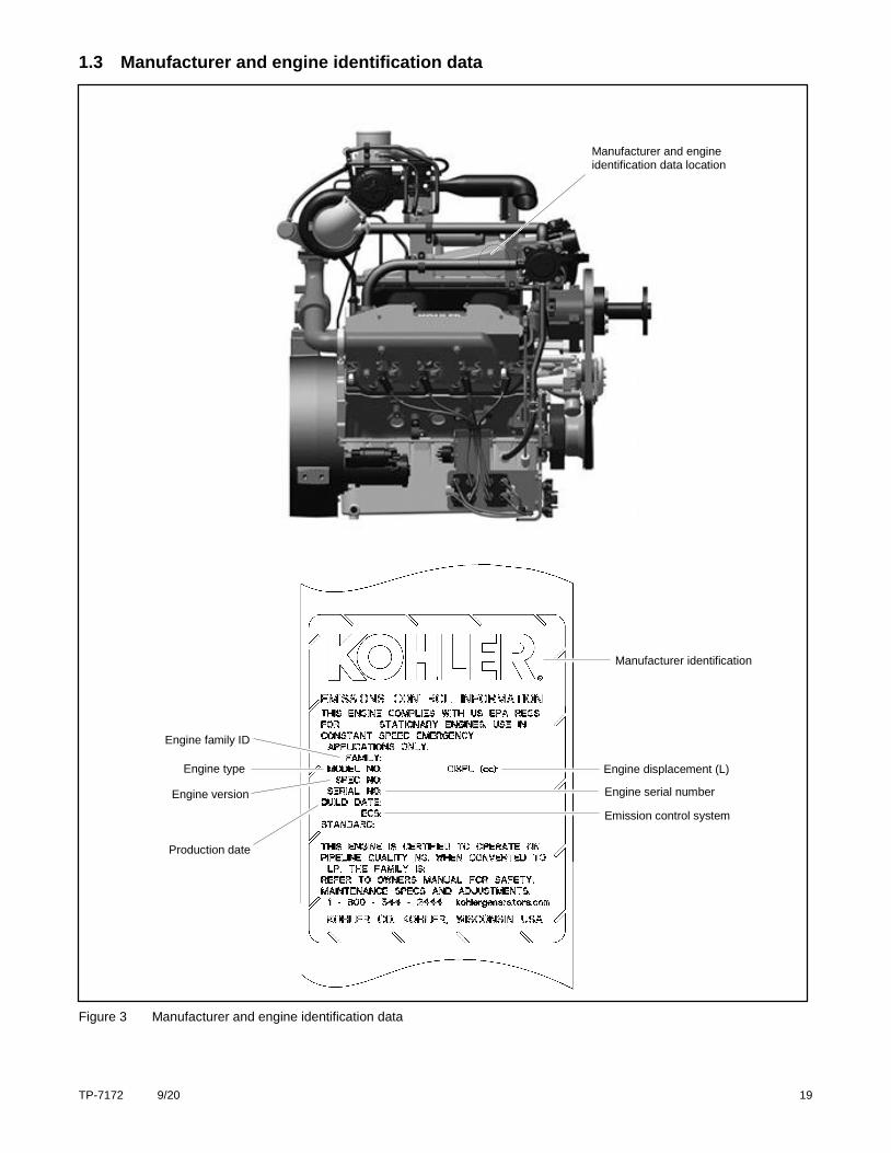
1.3 Manufacturer and engine identification data
Figure 3 Manufacturer and engine identification data
Engine serial number
Engine displacement (L)
Manufacturer identification
Engine family ID
Production date
Engine type
Emission control system
Engine version
Manufacturer and engine identification data location

20 TP-7172 9/20
TP-7172 9/20 21
Section 2. Operation
2.1 Introduction
These four-stroke internal combustion engines are certified to operate on either Propane, Liquid Petroleum Gas (LPG) or Natural
Gas (NG). System configuration is factory preset for NG.
The fuel system on this engine is a closed loop design. As the engine runs, sensors located at various points within the system
provide continuous operating feedback to the Engine Control Module (ECM). The ECM adjusts the engine speed, ignition timing,
and fuel supply in response to changes in the applied load, surrounding air temperature, operating temperature of the engine,
and amount of oxygen present in the exhaust.
Refer to the Operation Manual for the equipment using this engine for specific information on how fault codes are displayed.
2.2 Fuel System
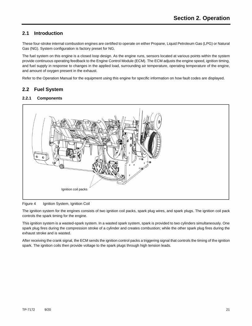
2.2.1 Components
Figure 4 Ignition System, Ignition Coil
The ignition system for the engines consists of two ignition coil packs, spark plug wires, and spark plugs. The ignition coil pack
controls the spark timing for the engine.
This ignition system is a wasted-spark system. In a wasted spark system, spark is provided to two cylinders simultaneously. One
spark plug fires during the compression stroke of a cylinder and creates combustion; while the other spark plug fires during the
exhaust stroke and is wasted.
After receiving the crank signal, the ECM sends the ignition control packs a triggering signal that controls the timing of the ignition
spark. The ignition coils then provide voltage to the spark plugs through high tension leads.
Ignition coil packs
22 TP-7172 9/20
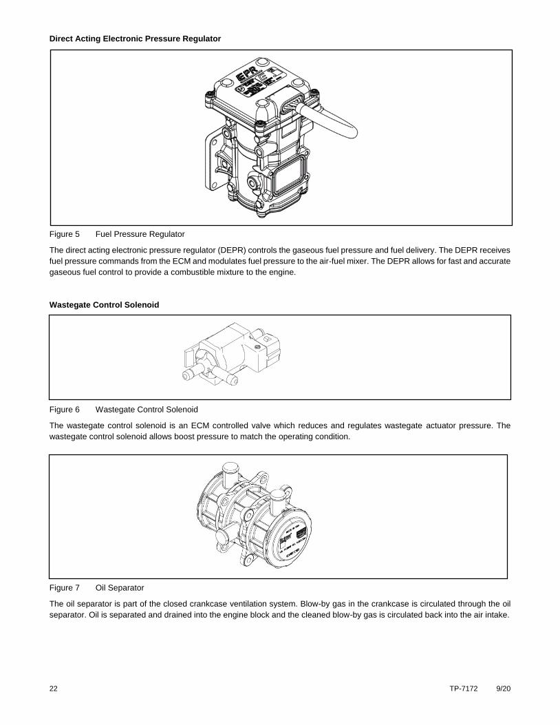
Direct Acting Electronic Pressure Regulator
Figure 5 Fuel Pressure Regulator
The direct acting electronic pressure regulator (DEPR) controls the gaseous fuel pressure and fuel delivery. The DEPR receives
fuel pressure commands from the ECM and modulates fuel pressure to the air-fuel mixer. The DEPR allows for fast and accurate
gaseous fuel control to provide a combustible mixture to the engine.
Wastegate Control Solenoid
Figure 6 Wastegate Control Solenoid
The wastegate control solenoid is an ECM controlled valve which reduces and regulates wastegate actuator pressure. The
wastegate control solenoid allows boost pressure to match the operating condition.
Figure 7 Oil Separator
The oil separator is part of the closed crankcase ventilation system. Blow-by gas in the crankcase is circulated through the oil
separator. Oil is separated and drained into the engine block and the cleaned blow-by gas is circulated back into the air intake.
TP-7172 9/20 23
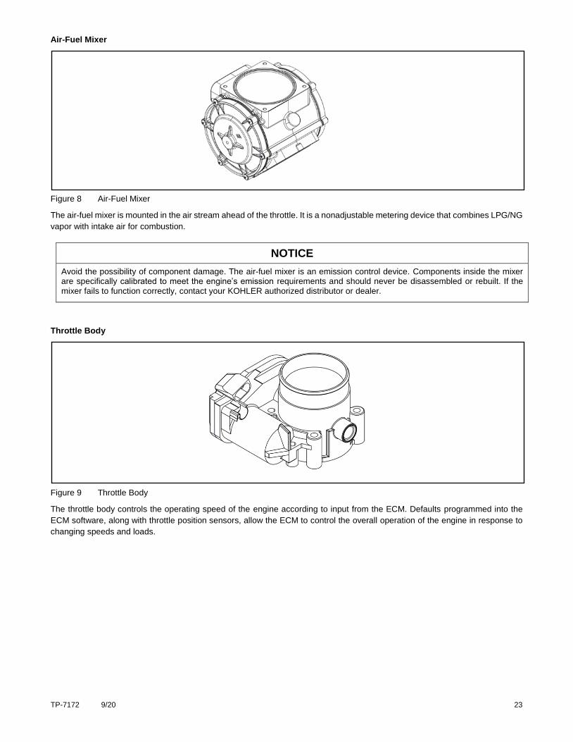
Air-Fuel Mixer
Figure 8 Air-Fuel Mixer
The air-fuel mixer is mounted in the air stream ahead of the throttle. It is a nonadjustable metering device that combines LPG/NG
vapor with intake air for combustion.
NOTICE
Avoid the possibility of component damage. The air-fuel mixer is an emission control device. Components inside the mixer are specifically calibrated to meet the engine’s emission requirements and should never be disassembled or rebuilt. If the mixer fails to function correctly, contact your KOHLER authorized distributor or dealer.
Throttle Body
Figure 9 Throttle Body
The throttle body controls the operating speed of the engine according to input from the ECM. Defaults programmed into the
ECM software, along with throttle position sensors, allow the ECM to control the overall operation of the engine in response to
changing speeds and loads.
24 TP-7172 9/20
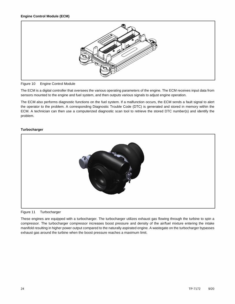
Engine Control Module (ECM)
Figure 10 Engine Control Module
The ECM is a digital controller that oversees the various operating parameters of the engine. The ECM receives input data from
sensors mounted to the engine and fuel system, and then outputs various signals to adjust engine operation.
The ECM also performs diagnostic functions on the fuel system. If a malfunction occurs, the ECM sends a fault signal to alert
the operator to the problem. A corresponding Diagnostic Trouble Code (DTC) is generated and stored in memory within the
ECM. A technician can then use a computerized diagnostic scan tool to retrieve the stored DTC number(s) and identify the
problem.
Turbocharger
Figure 11 Turbocharger
These engines are equipped with a turbocharger. The turbocharger utilizes exhaust gas flowing through the turbine to spin a
compressor. The turbocharger compressor increases boost pressure and density of the air/fuel mixture entering the intake
manifold resulting in higher power output compared to the naturally aspirated engine. A wastegate on the turbocharger bypasses
exhaust gas around the turbine when the boost pressure reaches a maximum limit.
TP-7172 9/20 25
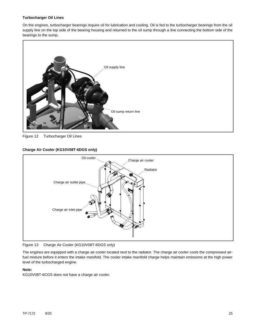
Turbocharger Oil Lines
On the engines, turbocharger bearings require oil for lubrication and cooling. Oil is fed to the turbocharger bearings from the oil
supply line on the top side of the bearing housing and returned to the oil sump through a line connecting the bottom side of the
bearings to the sump.
Figure 12 Turbocharger Oil Lines
Charge Air Cooler (KG10V08T-6DGS only)
Figure 13 Charge Air Cooler (KG10V08T-6DGS only)
The engines are equipped with a charge air cooler located next to the radiator. The charge air cooler cools the compressed air-
fuel mixture before it enters the intake manifold. The cooler intake manifold charge helps maintain emissions at the high power
level of the turbocharged engine.
Note:
KG10V08T-6CGS does not have a charge air cooler.
Charge air cooler
Radiator
Oil cooler
Charge air inlet pipe
Charge air outlet pipe
Oil supply line
Oil sump return line
26 TP-7172 9/20
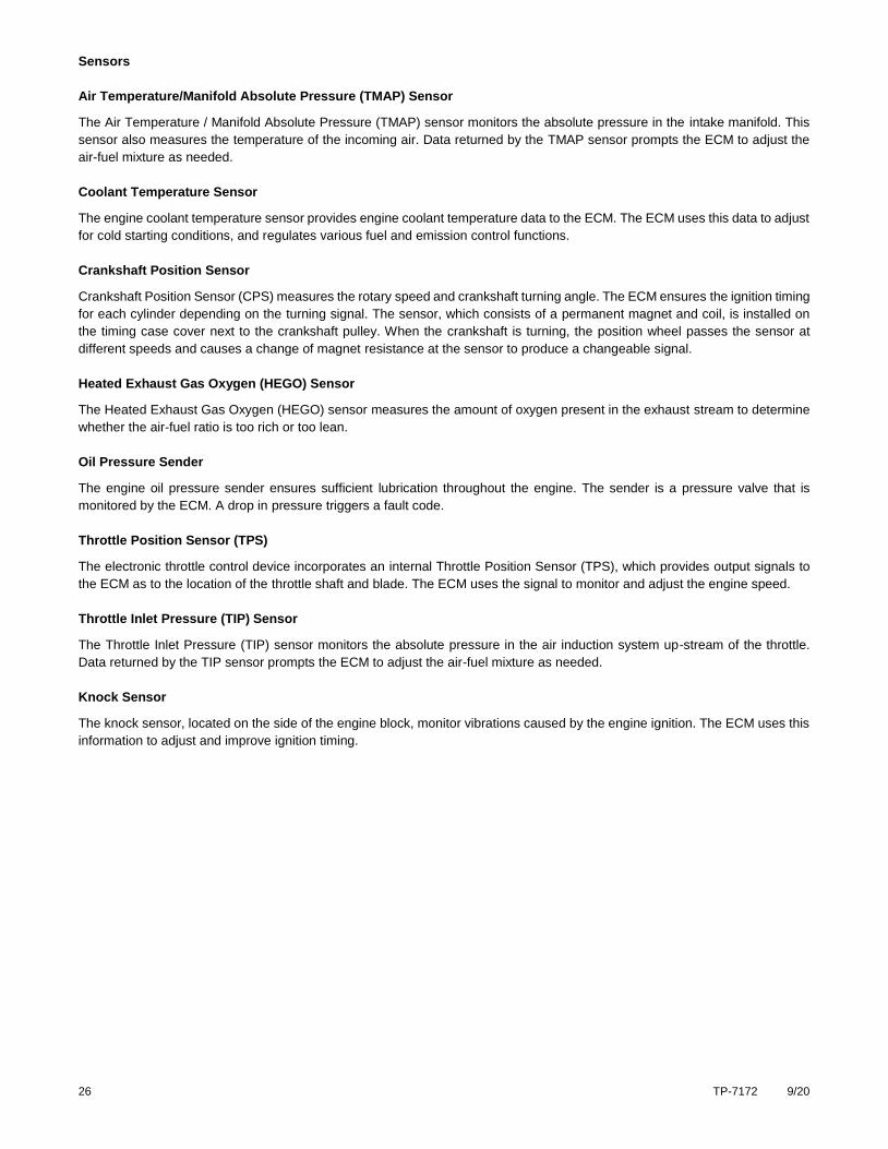
Sensors
Air Temperature/Manifold Absolute Pressure (TMAP) Sensor
The Air Temperature / Manifold Absolute Pressure (TMAP) sensor monitors the absolute pressure in the intake manifold. This
sensor also measures the temperature of the incoming air. Data returned by the TMAP sensor prompts the ECM to adjust the
air-fuel mixture as needed.
Coolant Temperature Sensor
The engine coolant temperature sensor provides engine coolant temperature data to the ECM. The ECM uses this data to adjust
for cold starting conditions, and regulates various fuel and emission control functions.
Crankshaft Position Sensor
Crankshaft Position Sensor (CPS) measures the rotary speed and crankshaft turning angle. The ECM ensures the ignition timing
for each cylinder depending on the turning signal. The sensor, which consists of a permanent magnet and coil, is installed on
the timing case cover next to the crankshaft pulley. When the crankshaft is turning, the position wheel passes the sensor at
different speeds and causes a change of magnet resistance at the sensor to produce a changeable signal.
Heated Exhaust Gas Oxygen (HEGO) Sensor
The Heated Exhaust Gas Oxygen (HEGO) sensor measures the amount of oxygen present in the exhaust stream to determine
whether the air-fuel ratio is too rich or too lean.
Oil Pressure Sender
The engine oil pressure sender ensures sufficient lubrication throughout the engine. The sender is a pressure valve that is
monitored by the ECM. A drop in pressure triggers a fault code.
Throttle Position Sensor (TPS)
The electronic throttle control device incorporates an internal Throttle Position Sensor (TPS), which provides output signals to
the ECM as to the location of the throttle shaft and blade. The ECM uses the signal to monitor and adjust the engine speed.
Throttle Inlet Pressure (TIP) Sensor
The Throttle Inlet Pressure (TIP) sensor monitors the absolute pressure in the air induction system up-stream of the throttle.
Data returned by the TIP sensor prompts the ECM to adjust the air-fuel mixture as needed.
Knock Sensor
The knock sensor, located on the side of the engine block, monitor vibrations caused by the engine ignition. The ECM uses this
information to adjust and improve ignition timing.
TP-7172 9/20 27
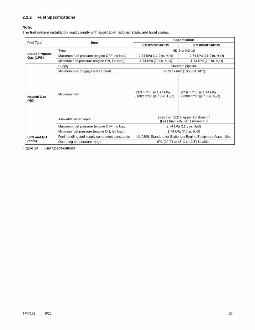
2.2.2 Fuel Specifications
Note:
The fuel system installation must comply with applicable national, state, and local codes.
Fuel Type Item Specification
KG10V08T-6CGS KG10V08T-6DGS
Liquid Propane Gas (LPG)
Type HD-5 or HD-10
Maximum fuel pressure (engine OFF, no load) 2.74 kPa (11.0 in. H2O) 2.74 kPa (11.0 in. H2O)
Minimum fuel pressure (engine ON, full load) 1.74 kPa (7.0 in. H2O) 1.74 kPa (7.0 in. H2O)
Natural Gas (NG)
Supply Standard pipeline
Minimum Fuel Supply Heat Content 37.257 kJ/m3 (1000 BTU/ft.3)
Minimum flow 53.3 m3/hr. @ 1.74 kPa (1882 ft3/hr @ 7.0 in. H2O)
67.9 m3/hr. @ 1.74 kPa (2398 ft3/hr @ 7.0 in. H2O)
Allowable water vapor Less than 112.3 kg per 1 million m3
(Less than 7 lb. per 1 million ft.3)
Maximum fuel pressure (engine OFF, no load) 2.74 kPa (11.0 in. H2O)
Minimum fuel pressure (engine ON, full load) 1.74 kPa (7.0 in. H2O)
LPG and NG (both)
Fuel handling and supply component constraints UL 2200: Standard for Stationary Engine Equipment Assemblies
Operating temperature range 0°C (32°F) to 45°C (113°F) Unaided
Figure 14 Fuel Specifications
28 TP-7172 9/20
2.2.3 Before Starting
WARNING Accidental starting. Can cause severe injury or death.
Disconnect the battery cables before working on the engine. Remove the negative (–) lead first when disconnecting the battery. Reconnect the negative (–) lead last when reconnecting the battery.
Disabling the engine. Accidental starting can cause severe injury or death. Before working on the engine or connected
equipment, disable the engine as follows: 1) Disconnect the ignition coil. 2) Remove the battery cables, negative (–) lead first. Reconnect the negative (–) lead last when reconnecting the battery. Follow these precautions to prevent the accidental starting of the engine.
To prevent possible injury or damage to equipment, carefully read and understand all information in this Operation Manual before
starting the engine. Follow the checklist below prior to each start up:
Perform a walk-around inspection, checking for damage, fluid leaks, loose or missing fasteners, or debris.
Check pipe and hose connections to make sure that they are tight.
Check engine oil level; add oil as needed. Inspect engine oil for signs of deterioration or contamination. See the
maintenance procedure for checking the engine oil.
Check engine coolant level; add coolant as needed. Inspect coolant for contamination. See the maintenance procedure
for checking the coolant level and condition.
Check battery connections to ensure that they are tight with no visible corrosion. Check level of battery electrolyte and
add fluid if necessary. See the maintenance procedure for checking the electrical system.
Check and clean cooling areas, air intake areas, and external surfaces of the engine, particularly if the engine has been
stored for a long period of time.
Check to make sure that air cleaner components, shrouds, equipment covers, and guards are in place and securely
fastened.
Check all electrical connections to make sure that they are tight, including those at the alternator, starter, spark plug,
and ignition coil. Repair damaged or loose wires or connectors before starting the engine.
Check the fuel system. Make sure that all connections are secure at the fuel supply line and at all fuel system
components. Do not start the engine if you can smell leaking gas.
LPG only: check the fuel level in the fuel tank, and refill if necessary.
TP-7172 9/20 29
2.2.4 Starting
The specific engine starting sequence varies depending on the equipment that this engine powers. For more information, refer
to the Operation Manual for the equipment using this engine.
WARNING Carbon monoxide. Can cause severe nausea, fainting, or death.
The exhaust system must be leakproof and routinely inspected.
Carbon monoxide symptoms. Carbon monoxide can cause severe nausea, fainting, or death. Carbon monoxide is a
poisonous gas present in exhaust gases. Carbon monoxide is an odorless, colorless, tasteless, nonirritating gas that can cause death if inhaled for even a short time. Carbon monoxide poisoning symptoms include but are not limited to the following:
Light-headedness, dizziness
Physical fatigue, weakness in joints and muscles
Sleepiness, mental fatigue, inability to concentrate or speak clearly, blurred vision
Stomachache, vomiting, nausea
If experiencing any of these symptoms and carbon monoxide poisoning is possible, seek fresh air immediately and remain active. Do not sit, lie down, or fall asleep. Alert others to the possibility of carbon monoxide poisoning. Seek medical attention if the condition of affected persons does not improve within minutes of breathing fresh air.
Engine Operation. Carbon monoxide can cause severe nausea, fainting, or death. Engine exhaust gases contain
poisonous carbon monoxide. Carbon monoxide is an odorless, colorless, tasteless, nonirritating gas that can cause death if inhaled for even a short time. Avoid breathing exhaust fumes when working on or near the engine. Never operate the engine inside a building. Never operate the engine where exhaust gas could seep inside or be drawn into a potentially occupied building through windows, air intake vents, or other openings.
WARNING Moving parts. Can cause severe injury or death.
Operate the engine only when all guards and electrical enclosures are in place. Stay away from moving parts while the engine is in operation.
Servicing the engine when it is operating. Exposed moving parts can cause severe injury or death. Keep hands, feet,
hair, clothing, and test leads away from the belts and pulleys when the engine is running. Replace guards, screens, and covers before operating the engine.
WARNING Explosive fuel vapors. Can cause fires and severe burns.
If a gaseous odor is detected, ventilate the area and contact an authorized service technician.
The fuel system. Explosive fuel vapors can cause severe injury or death. Vaporized fuels are highly explosive. Use extreme
care when handling and storing fuels. Store fuels in a well-ventilated area away from spark-producing equipment and out of the reach of children. Never add fuel to the tank while the engine is running because spilled fuel may ignite on contact with hot parts or from sparks. Do not smoke or permit flames or sparks to occur near sources of spilled fuel or fuel vapors. Keep the fuel lines and connections tight and in good condition. Do not replace flexible fuel lines with rigid lines. Use flexible sections to avoid fuel line breakage caused by vibration. Do not operate the engine in the presence of fuel leaks, fuel accumulation, or sparks. Repair fuel systems before resuming engine operation.
If the engine does not start after 15 seconds of cranking, wait at least 15 seconds before trying again. Do not crank the starter
longer than three crank cycles. After three crank cycles, the controller will display faults. Longer crank times can overheat the
starter and drain the battery.
30 TP-7172 9/20
If the engine does not start after three attempts, discontinue the starting procedure. Perform troubleshooting to locate the
problem(s) and correct them before trying again.
2.2.5 Cold Weather Starting
WARNING Handling caustic engine fluids and chemical products. Can cause severe chemical burns, nausea, fainting, or death.
Most chemicals such as used engine oil, antifreeze/coolant, rustproofing agent, inhibiting oil, degreasing agent, spray paint, and adhesives are hazardous to health. Read and follow the user information found on the packaging. Avoid inhalation and skin contact. Use only in well-ventilated areas and use a protective mask when spraying. Store engine fluids and chemical products in a locked cabinet. Contact your local recycling center for disposal information and locations.
WARNING Explosive fuel vapors. Can cause fires and severe burns.
If a gaseous odor is detected, ventilate the area and contact an authorized service technician.
The fuel system. Explosive fuel vapors can cause severe injury or death. Vaporized fuels are highly explosive. Use extreme
care when handling and storing fuels. Store fuels in a well-ventilated area away from spark-producing equipment and out of the reach of children. Never add fuel to the tank while the engine is running because spilled fuel may ignite on contact with hot parts or from sparks. Do not smoke or permit flames or sparks to occur near sources of spilled fuel or fuel vapors. Keep the fuel lines and connections tight and in good condition. Do not replace flexible fuel lines with rigid lines. Use flexible sections to avoid fuel line breakage caused by vibration. Do not operate the engine in the presence of fuel leaks, fuel accumulation, or sparks. Repair fuel systems before resuming engine operation.
Cold weather puts added stress on the engine during start up. To start the engine in cold weather:
Make sure that the engine oil is appropriate for the ambient operating temperature. See the maintenance section for
fluid specifications. Drain and replace the engine oil if necessary.
Disconnect all applied loads and/or equipment before cranking the starter.
Allow the engine to run, unloaded, for about 5 minutes after cold weather start up.
TP-7172 9/20 31
2.2.6 Monitoring Engine Operation
WARNING Carbon monoxide. Can cause severe nausea, fainting, or death.
The exhaust system must be leakproof and routinely inspected.
Carbon monoxide symptoms. Carbon monoxide can cause severe nausea, fainting, or death. Carbon monoxide is a
poisonous gas present in exhaust gases. Carbon monoxide is an odorless, colorless, tasteless, nonirritating gas that can cause death if inhaled for even a short time. Carbon monoxide poisoning symptoms include but are not limited to the following:
Light-headedness, dizziness
Physical fatigue, weakness in joints and muscles
Sleepiness, mental fatigue, inability to concentrate or speak clearly, blurred vision
Stomachache, vomiting, nausea
If experiencing any of these symptoms and carbon monoxide poisoning is possible, seek fresh air immediately and remain active. Do not sit, lie down, or fall asleep. Alert others to the possibility of carbon monoxide poisoning. Seek medical attention if the condition of affected persons does not improve within minutes of breathing fresh air.
Engine Operation. Carbon monoxide can cause severe nausea, fainting, or death. Engine exhaust gases contain
poisonous carbon monoxide. Carbon monoxide is an odorless, colorless, tasteless, nonirritating gas that can cause death if inhaled for even a short time. Avoid breathing exhaust fumes when working on or near the engine. Never operate the engine inside a building. Never operate the engine where exhaust gas could seep inside or be drawn into a potentially occupied building through windows, air intake vents, or other openings.
CAUTION Hazardous voltage. Electrical shock can cause injury.
Do not touch wires while the engine is running. Stop the engine and disconnect the battery leads, negative (-) lead first, before servicing the engine.
Check for the following items as the engine runs.
Gas/air leaks: check for leakage from fuel pipes, cooling pipes, or air pipes.
Exhaust: check for detonation, backfire, or knocking. Watch for excessive smoke or abnormal color.
Noise: listen for rattles or other abnormal noise.
Electrical: check for burnt smell from hot electrical equipment.
Fluid leaks: check for leaking oil or coolant.
Gauges: check oil pressure, coolant temperature, and other operating parameters.
If any abnormal or unusual conditions are detected, stop the engine immediately and perform troubleshooting diagnostics before
resuming operation.
2.2.7 Stopping
1. Disconnect all applied loads if possible, along with power take-off (PTO) attachments, before stopping the engine.
2. If the engine has been running under a heavy load, remove the load and allow it to run for an additional 2-3 minutes
before stopping. This action will help to cool the engine slightly before shutdown.
The specific engine-stopping sequence varies depending on the equipment that this engine powers. For more information, refer
to the Operation Manual for the equipment using this engine.

32 TP-7172 9/20
TP-7172 9/20 33
Section 3. Maintenance
3.1 Introduction
Preventive maintenance is critical to prolonging the life of the engine and keeping it in optimum working condition. As the engine
runs, fasteners may loosen, parts may become worn, clearances change, and oil picks up dirt and contaminants. The engine
may eventually become hard to start, or may exhibit other symptoms such as decreased power output or increased fuel
consumption.
Regularly scheduled maintenance will help to prevent or reduce the impact of these performance issues. To keep the engine
working reliably, perform all preventive maintenance tasks described in this section.
3.2 Safety Precautions and Instructions
WARNING Accidental starting. Can cause severe injury or death.
Disconnect the battery cables before working on the engine. Remove the negative (–) lead first when disconnecting the battery. Reconnect the negative (–) lead last when reconnecting the battery.
Disabling the engine. Accidental starting can cause severe injury or death. Before working on the engine or connected
equipment, disable the engine as follows: 1) Disconnect the ignition coil. 2) Remove the battery cables, negative (–) lead first. Reconnect the negative (–) lead last when reconnecting the battery. Follow these precautions to prevent the accidental starting of the engine.
WARNING Handling caustic engine fluids and chemical products. Can cause severe chemical burns, nausea, fainting, or death.
Most chemicals such as used engine oil, antifreeze/coolant, rustproofing agent, inhibiting oil, degreasing agent, spray paint, and adhesives are hazardous to health. Read and follow the user information found on the packaging. Avoid inhalation and skin contact. Use only in well-ventilated areas and use a protective mask when spraying. Store engine fluids and chemical products in a locked cabinet. Contact your local recycling center for disposal information and locations.
Used engine oil. Contact with used engine oil may cause severe skin irritation. Repeated and prolonged skin exposure may have other health risks. Used engine oil is a suspected carcinogen. Avoid contact with skin. Thoroughly wash your hands
and nails with soap and water shortly after handling used engine oil. Wash or dispose of clothing or rags containing used engine oil. Dispose of used engine oil in a responsible manner. Contact your local recycling center for disposal information and locations.
WARNING Hot engine and exhaust system. Can cause severe injury or death.
Do not work on the engine until it cools.
Servicing the exhaust system. Hot parts can cause severe injury or death. Do not touch hot engine parts. The engine and
exhaust system components become extremely hot during operation.
WARNING Hot coolant and steam. Can cause severe injury or death.
Before removing the pressure cap, stop the engine and allow it to cool. Then loosen the pressure cap to relieve pressure.
34 TP-7172 9/20
CAUTION Hazardous voltage. Electrical shock can cause injury.
Do not touch wires while the engine is running. Stop the engine and disconnect the battery leads, negative (-) lead first, before servicing the engine.
Servicing the engine when it is operating. Exposed moving parts can cause severe injury or death. Keep hands, feet,
hair, clothing, and test leads away from the belts and pulleys when the engine is running. Replace guards, screens, and covers before operating the engine.
WARNING Moving parts. Can cause severe injury or death.
Operate the engine only when all guards and electrical enclosures are in place. Stay away from moving parts while the engine is in operation.
WARNING Explosive fuel vapors. Can cause severe injury or death.
Use extreme care when handling, storing, and using fuels.
The fuel system. Explosive fuel vapors can cause severe injury or death. Vaporized fuels are highly explosive. Use extreme
care when handling and storing fuels. Store fuels in a well-ventilated area away from spark-producing equipment and out of the reach of children. Never add fuel to the tank while the engine is running because spilled fuel may ignite on contact with hot parts or from sparks. Do not smoke or permit flames or sparks to occur near sources of spilled fuel or fuel vapors. Keep the fuel lines and connections tight and in good condition. Do not replace flexible fuel lines with rigid lines. Use flexible sections to avoid fuel line breakage caused by vibration. Do not operate the engine in the presence of fuel leaks, fuel accumulation, or sparks. Repair fuel systems before resuming engine operation.
Gas fuel leaks. Explosive fuel vapors can cause severe injury or death. Fuel leakage can cause an explosion. Check the
LPG vapor or natural gas fuel system for leakage by using a soap and water solution with the fuel system test pressurized to 6–8 ounces per square inch (10–14 inches water column). Do not use a soap solution containing either ammonia or chlorine because both prevent bubble formation. A successful test depends on the ability of the solution to bubble.
TP-7172 9/20 35
3.3 Fluid Specifications
3.3.1 Oil Recommendations
Kohler recommends Kohler Genuine Oil, 10W-40 or equivalent.
Kohler Genuine Oil is fully synthetic and engineered specifically for gaseous-fueled (NG/LPG) engines requiring SAE 10W-40
oil.
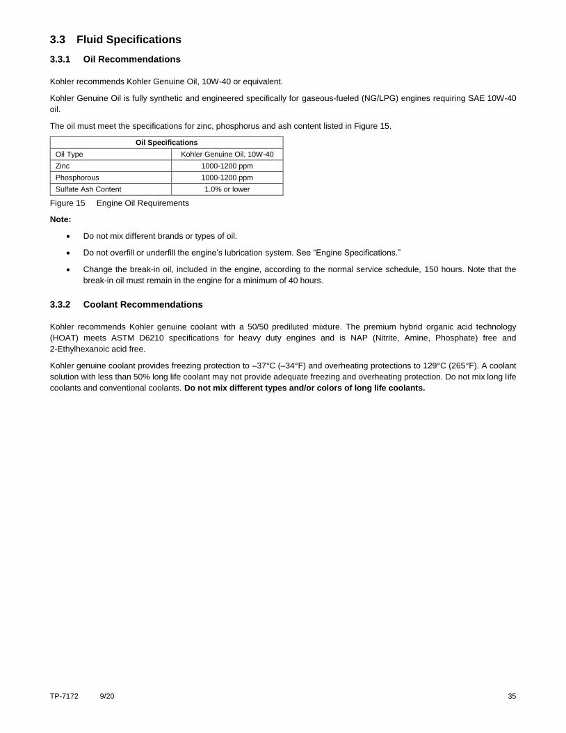
The oil must meet the specifications for zinc, phosphorus and ash content listed in Figure 15.
Oil Specifications
Oil Type Kohler Genuine Oil, 10W-40
Zinc 1000-1200 ppm
Phosphorous 1000-1200 ppm
Sulfate Ash Content 1.0% or lower
Figure 15 Engine Oil Requirements
Note:
Do not mix different brands or types of oil.
Do not overfill or underfill the engine’s lubrication system. See “Engine Specifications.”
Change the break-in oil, included in the engine, according to the normal service schedule, 150 hours. Note that the
break-in oil must remain in the engine for a minimum of 40 hours.
3.3.2 Coolant Recommendations
Kohler recommends Kohler genuine coolant with a 50/50 prediluted mixture. The premium hybrid organic acid technology
(HOAT) meets ASTM D6210 specifications for heavy duty engines and is NAP (Nitrite, Amine, Phosphate) free and
2-Ethylhexanoic acid free.
Kohler genuine coolant provides freezing protection to –37°C (–34°F) and overheating protections to 129°C (265°F). A coolant
solution with less than 50% long life coolant may not provide adequate freezing and overheating protection. Do not mix long life
coolants and conventional coolants. Do not mix different types and/or colors of long life coolants.
36 TP-7172 9/20
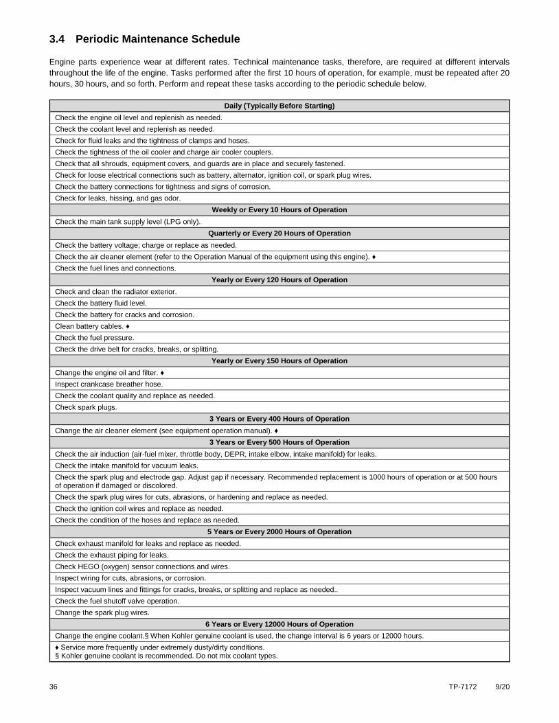
3.4 Periodic Maintenance Schedule
Engine parts experience wear at different rates. Technical maintenance tasks, therefore, are required at different intervals
throughout the life of the engine. Tasks performed after the first 10 hours of operation, for example, must be repeated after 20
hours, 30 hours, and so forth. Perform and repeat these tasks according to the periodic schedule below.
Daily (Typically Before Starting)
Check the engine oil level and replenish as needed.
Check the coolant level and replenish as needed.
Check for fluid leaks and the tightness of clamps and hoses.
Check the tightness of the oil cooler and charge air cooler couplers.
Check that all shrouds, equipment covers, and guards are in place and securely fastened.
Check for loose electrical connections such as battery, alternator, ignition coil, or spark plug wires.
Check the battery connections for tightness and signs of corrosion.
Check for leaks, hissing, and gas odor.
Weekly or Every 10 Hours of Operation
Check the main tank supply level (LPG only).
Quarterly or Every 20 Hours of Operation
Check the battery voltage; charge or replace as needed.
Check the air cleaner element (refer to the Operation Manual of the equipment using this engine). ♦
Check the fuel lines and connections.
Yearly or Every 120 Hours of Operation
Check and clean the radiator exterior.
Check the battery fluid level.
Check the battery for cracks and corrosion.
Clean battery cables. ♦
Check the fuel pressure.
Check the drive belt for cracks, breaks, or splitting.
Yearly or Every 150 Hours of Operation
Change the engine oil and filter. ♦
Inspect crankcase breather hose.
Check the coolant quality and replace as needed.
Check spark plugs.
3 Years or Every 400 Hours of Operation
Change the air cleaner element (see equipment operation manual). ♦
3 Years or Every 500 Hours of Operation
Check the air induction (air-fuel mixer, throttle body, DEPR, intake elbow, intake manifold) for leaks.
Check the intake manifold for vacuum leaks.
Check the spark plug and electrode gap. Adjust gap if necessary. Recommended replacement is 1000 hours of operation or at 500 hours of operation if damaged or discolored.
Check the spark plug wires for cuts, abrasions, or hardening and replace as needed.
Check the ignition coil wires and replace as needed.
Check the condition of the hoses and replace as needed.
5 Years or Every 2000 Hours of Operation
Check exhaust manifold for leaks and replace as needed.
Check the exhaust piping for leaks.
Check HEGO (oxygen) sensor connections and wires.
Inspect wiring for cuts, abrasions, or corrosion.
Inspect vacuum lines and fittings for cracks, breaks, or splitting and replace as needed..
Check the fuel shutoff valve operation.
Change the spark plug wires.
6 Years or Every 12000 Hours of Operation
Change the engine coolant.§ When Kohler genuine coolant is used, the change interval is 6 years or 12000 hours.
♦ Service more frequently under extremely dusty/dirty conditions. § Kohler genuine coolant is recommended. Do not mix coolant types.
TP-7172 9/20 37
3.5 Engine
3.5.1 Check Engine Oil
Check the engine oil level daily, typically before starting the engine. Inspect the oil for signs of deterioration, discoloration,
thinning, or water contamination. If any of these conditions exist, the oil quality has been compromised and should be replaced.
Required materials:
Clean, dry cloth.
Fresh engine oil. (See the section “Oil Recommendations”)
Procedure:
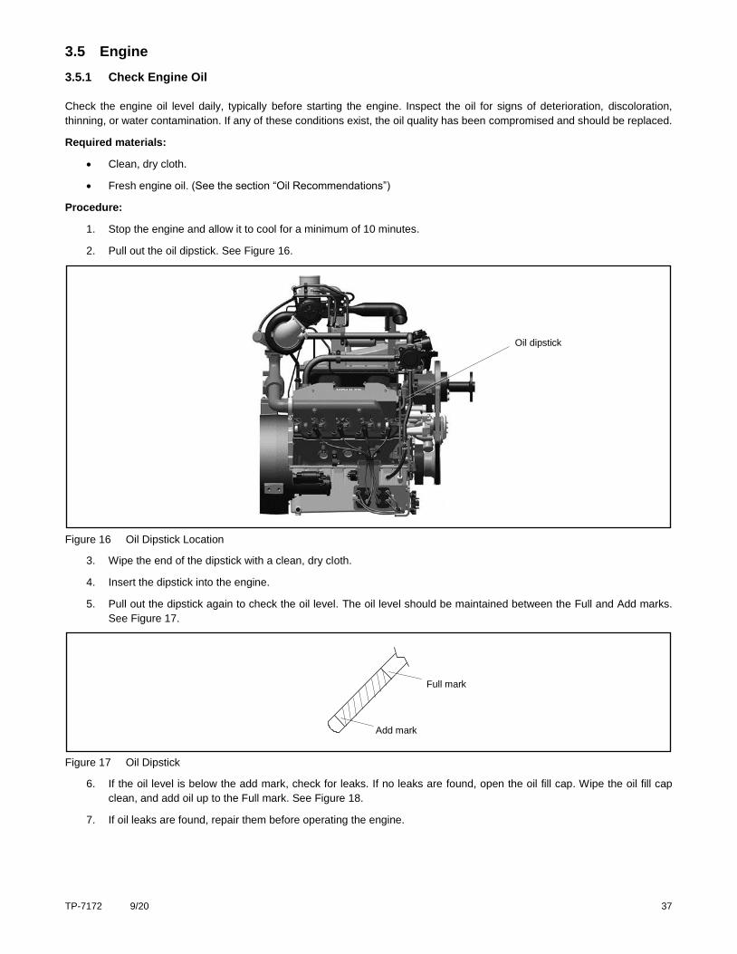
1. Stop the engine and allow it to cool for a minimum of 10 minutes.
2. Pull out the oil dipstick. See Figure 16.
Figure 16 Oil Dipstick Location
3. Wipe the end of the dipstick with a clean, dry cloth.
4. Insert the dipstick into the engine.
5. Pull out the dipstick again to check the oil level. The oil level should be maintained between the Full and Add marks.
See Figure 17.
Figure 17 Oil Dipstick
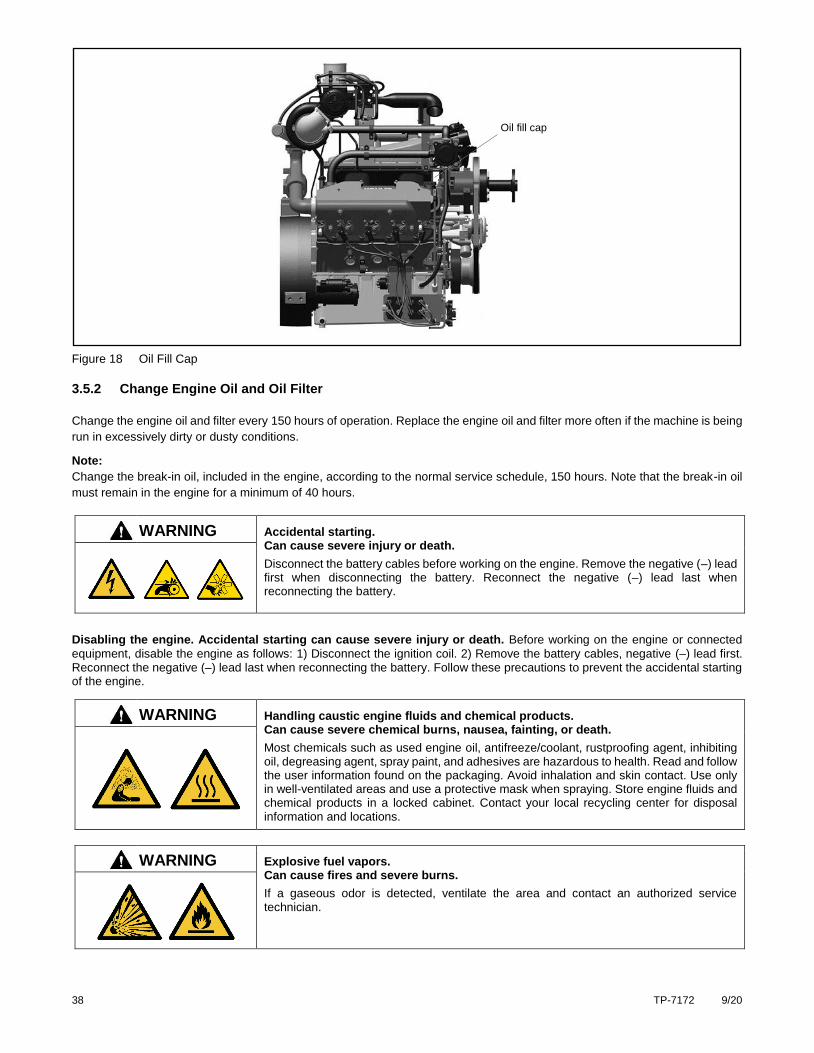
6. If the oil level is below the add mark, check for leaks. If no leaks are found, open the oil fill cap. Wipe the oil fill cap
clean, and add oil up to the Full mark. See Figure 18.
7. If oil leaks are found, repair them before operating the engine.
Full mark
Add mark
Oil dipstick
38 TP-7172 9/20
Figure 18 Oil Fill Cap
3.5.2 Change Engine Oil and Oil Filter
Change the engine oil and filter every 150 hours of operation. Replace the engine oil and filter more often if the machine is being
run in excessively dirty or dusty conditions.
Note:
Change the break-in oil, included in the engine, according to the normal service schedule, 150 hours. Note that the break-in oil
must remain in the engine for a minimum of 40 hours.
WARNING Accidental starting. Can cause severe injury or death.
Disconnect the battery cables before working on the engine. Remove the negative (–) lead first when disconnecting the battery. Reconnect the negative (–) lead last when reconnecting the battery.
Disabling the engine. Accidental starting can cause severe injury or death. Before working on the engine or connected
equipment, disable the engine as follows: 1) Disconnect the ignition coil. 2) Remove the battery cables, negative (–) lead first. Reconnect the negative (–) lead last when reconnecting the battery. Follow these precautions to prevent the accidental starting of the engine.
WARNING Handling caustic engine fluids and chemical products. Can cause severe chemical burns, nausea, fainting, or death.
Most chemicals such as used engine oil, antifreeze/coolant, rustproofing agent, inhibiting oil, degreasing agent, spray paint, and adhesives are hazardous to health. Read and follow the user information found on the packaging. Avoid inhalation and skin contact. Use only in well-ventilated areas and use a protective mask when spraying. Store engine fluids and chemical products in a locked cabinet. Contact your local recycling center for disposal information and locations.
WARNING Explosive fuel vapors. Can cause fires and severe burns.
If a gaseous odor is detected, ventilate the area and contact an authorized service technician.
Oil fill cap
TP-7172 9/20 39
The fuel system. Explosive fuel vapors can cause severe injury or death. Vaporized fuels are highly explosive. Use extreme
care when handling and storing fuels. Store fuels in a well-ventilated area away from spark-producing equipment and out of the reach of children. Never add fuel to the tank while the engine is running because spilled fuel may ignite on contact with hot parts or from sparks. Do not smoke or permit flames or sparks to occur near sources of spilled fuel or fuel vapors. Keep the fuel lines and connections tight and in good condition. Do not replace flexible fuel lines with rigid lines. Use flexible sections to avoid fuel line breakage caused by vibration. Do not operate the engine in the presence of fuel leaks, fuel accumulation, or sparks. Repair fuel systems before resuming engine operation.
WARNING Hot engine and exhaust system. Can cause severe injury or death.
Do not work on the engine until it cools.
Hot engine components. Can cause severe injury or death. Never operate the engine with heat shields or guards removed.
Required materials:
Fresh engine oil (refer to the oil recommendations in the maintenance section)
Collection container for drained oil
Replacement oil filter
Oil filter wrench
Clean, dry cloth
Drop cloth to protect work surface
Change the engine oil and oil filter:
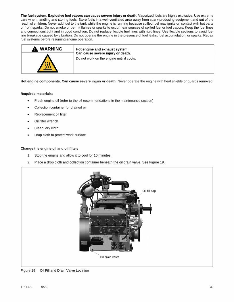
1. Stop the engine and allow it to cool for 10 minutes.
2. Place a drop cloth and collection container beneath the oil drain valve. See Figure 19.
Figure 19 Oil Fill and Drain Valve Location
Oil fill cap
Oil drain valve
40 TP-7172 9/20
3. Open the oil drain valve and allow the oil to drain into the container.
4. Using an oil filter wrench, remove the old oil filter.
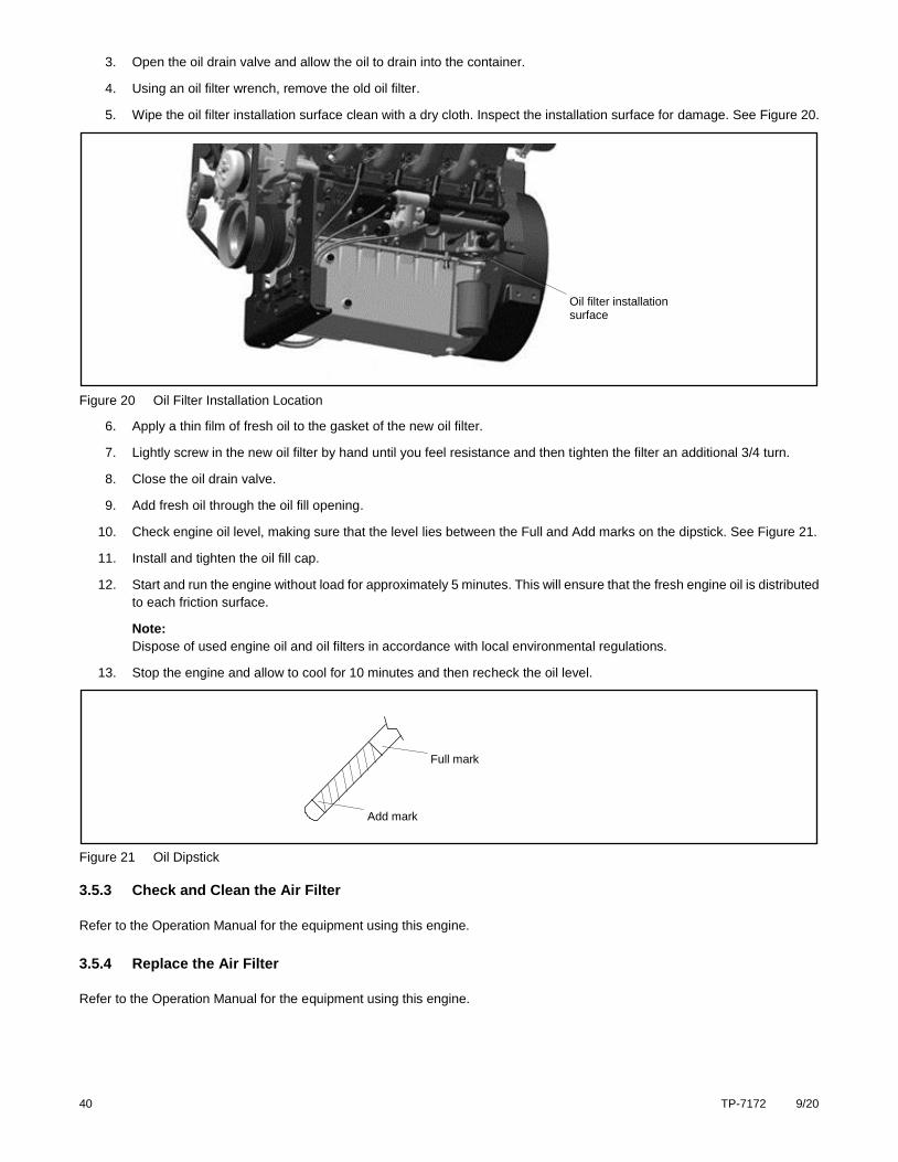
5. Wipe the oil filter installation surface clean with a dry cloth. Inspect the installation surface for damage. See Figure 20.
Figure 20 Oil Filter Installation Location
6. Apply a thin film of fresh oil to the gasket of the new oil filter.
7. Lightly screw in the new oil filter by hand until you feel resistance and then tighten the filter an additional 3/4 turn.
8. Close the oil drain valve.
9. Add fresh oil through the oil fill opening.
10. Check engine oil level, making sure that the level lies between the Full and Add marks on the dipstick. See Figure 21.
11. Install and tighten the oil fill cap.
12. Start and run the engine without load for approximately 5 minutes. This will ensure that the fresh engine oil is distributed
to each friction surface.
Note:
Dispose of used engine oil and oil filters in accordance with local environmental regulations.
13. Stop the engine and allow to cool for 10 minutes and then recheck the oil level.
Figure 21 Oil Dipstick
3.5.3 Check and Clean the Air Filter
Refer to the Operation Manual for the equipment using this engine.
3.5.4 Replace the Air Filter
Refer to the Operation Manual for the equipment using this engine.
Full mark
Add mark
Oil filter installation surface
TP-7172 9/20 41
3.5.5 Check, Adjust and Replace the Spark Plugs
Damaged, loose, or improperly adjusted spark plugs can overheat or cause engine problems such as misfiring, hesitation, or
knocking. Check the spark plugs after every 500 hours of operation
CAUTION Hazardous voltage. Electrical shock can cause injury.
Do not touch wires while the engine is running. Stop the engine and disconnect the battery leads, negative (-) lead first, before servicing the engine.
WARNING Hot engine and exhaust system. Can cause severe injury or death.
Do not work on the engine until it cools.
Hot engine components. Can cause severe injury or death. Never operate the engine with heat shields or guards removed.
Required materials:
Spark plug wrench
Torque wrench
Spark plug gap tool
Clean, dry cloth
Replacement spark plugs. See spark plug specifications in the Specifications section.
Procedure:
1. Stop the engine and allow it to cool.
Note:
Label or mark spark plug wires before disconnecting. Spark plug wires must be reconnected in the same order as removed.
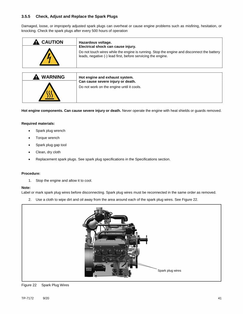
2. Use a cloth to wipe dirt and oil away from the area around each of the spark plug wires. See Figure 22.
Figure 22 Spark Plug Wires
Spark plug wires
42 TP-7172 9/20
3. Remove the metal boot from the spark plug wires. Disconnect the spark plug wires and remove the grounding spring.
4. Use a spark plug wrench to remove the spark plugs.
5. Inspect the body of each spark plug for cracks, damage, or discoloration and check that the spark plug washer is in
good condition.
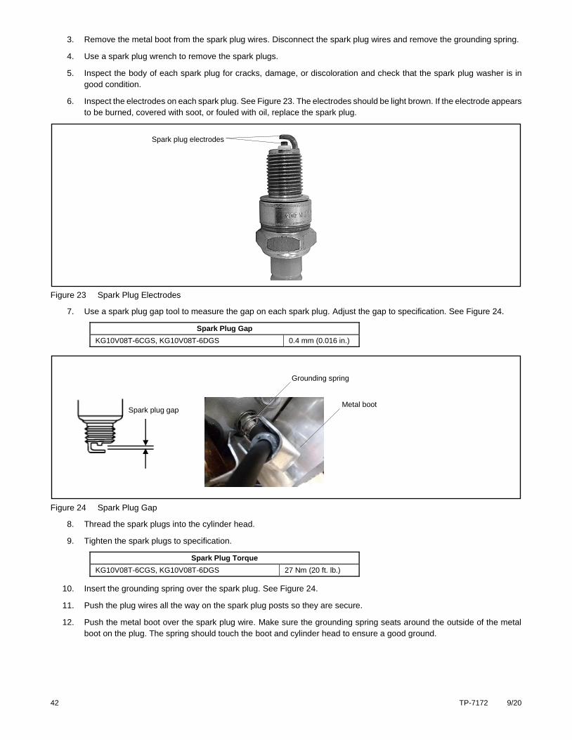
6. Inspect the electrodes on each spark plug. See Figure 23. The electrodes should be light brown. If the electrode appears
to be burned, covered with soot, or fouled with oil, replace the spark plug.
Figure 23 Spark Plug Electrodes
7. Use a spark plug gap tool to measure the gap on each spark plug. Adjust the gap to specification. See Figure 24.
Spark Plug Gap
KG10V08T-6CGS, KG10V08T-6DGS 0.4 mm (0.016 in.)
Figure 24 Spark Plug Gap
8. Thread the spark plugs into the cylinder head.
9. Tighten the spark plugs to specification.
Spark Plug Torque
KG10V08T-6CGS, KG10V08T-6DGS 27 Nm (20 ft. lb.)
10. Insert the grounding spring over the spark plug. See Figure 24.
11. Push the plug wires all the way on the spark plug posts so they are secure.
12. Push the metal boot over the spark plug wire. Make sure the grounding spring seats around the outside of the metal
boot on the plug. The spring should touch the boot and cylinder head to ensure a good ground.
Spark plug gap
Grounding spring
Metal boot
Spark plug electrodes
TP-7172 9/20 43
3.5.6 Ignition Timing
The ignition system consists of two ignition coil packs which provide voltage to the spark plugs. The ECM uses information from
the crankshaft position sensors to optimize ignition timing.
Contact your Kohler authorized distributor/dealer for assistance with ignition-related performance issues.
3.6 Electrical System
3.6.1 Check Battery and Connections
Check the condition of the battery and connections according to the intervals specified in “Periodic Maintenance Schedule.”
Specific items to look for are:
Loose or missing fasteners on the battery hold-down.
Loose cable connections.
Frayed, cut, or broken cables.
Cracks in battery cell cover or case.
Dirt, oil, or water contamination.
Corrosion at battery terminals.
Reduction in voltage or ability to hold a charge.
Repair or replace the battery and/or components as needed. Use only replacement parts that are equivalent to the original
equipment. Contact your Kohler authorized distributor/dealer for assistance.
WARNING Sulfuric acid in batteries. Can cause severe injury or death.
Wear protective goggles and clothing. Battery acid may cause blindness and burn skin.
WARNING Explosion. Can cause severe injury or death. Relays in the battery charger cause arcs or sparks.
Locate the battery in a well‐ventilated area. Isolate the battery charger from explosive
fumes.
Battery electrolyte is a diluted sulfuric acid. Battery acid can cause severe injury or death. Battery acid can cause
blindness and burn skin. Always wear splashproof safety goggles, rubber gloves, and boots when servicing the battery. Do not open a sealed battery or mutilate the battery case. If battery acid splashes in the eyes or on the skin, immediately flush the affected area for 15 minutes with large quantities of clean water. Seek immediate medical aid in the case of eye contact. Never add acid to a battery after placing the battery in service, as this may result in hazardous spattering of battery acid.
Battery acid cleanup. Battery acid can cause severe injury or death. Battery acid is electrically conductive and corrosive.
Add 500 g (1 lb.) of bicarbonate of soda (baking soda) to a container with 4 L (1 gal.) of water and mix the neutralizing solution. Pour the neutralizing solution on the spilled battery acid and continue to add the neutralizing solution to the spilled battery acid until all evidence of a chemical reaction (foaming) has ceased. Flush the resulting liquid with water and dry the area.
Battery gases. Explosion can cause severe injury or death. Battery gases can cause an explosion. Do not smoke or permit
flames or sparks to occur near a battery at any time, particularly when it is charging. Do not dispose of a battery in a fire. To prevent burns and sparks that could cause an explosion, avoid touching the battery terminals with tools or other metal objects. Remove all jewelry before servicing the equipment. Discharge static electricity from your body before touching batteries by first touching a grounded metal surface away from the battery. To avoid sparks, do not disturb the battery charger connections while the battery is charging. Always turn the battery charger off before disconnecting the battery connections. Ventilate the compartments containing batteries to prevent accumulation of explosive gases.
44 TP-7172 9/20
Battery short circuits. Explosion can cause severe injury or death. Short circuits can cause bodily injury and/or equipment
damage. Disconnect the battery before maintenance. Remove all jewelry before servicing the equipment. Use tools with insulated handles. Remove the negative (–) lead first when disconnecting the battery. Reconnect the negative (–) lead last when reconnecting the battery. Never connect the negative (–) battery cable to the positive (+) connection terminal of the starter solenoid. Do not test the battery condition by shorting the terminals together.
3.6.2 Check and Adjust the Drive Belt
A worn, stretched, or damaged drive belt may fail, especially under heavy loads. Check the condition of the drive belt regularly and adjust belt tension as needed.
WARNING Accidental starting. Can cause severe injury or death.
Disconnect the battery cables before working on the engine. Remove the negative (–) lead first when disconnecting the battery. Reconnect the negative (–) lead last when reconnecting the battery.
Disabling the engine. Accidental starting can cause severe injury or death. Before working on the engine or connected
equipment, disable the engine as follows: 1) Disconnect the ignition coil. 2) Remove the battery cables, negative (–) lead first. Reconnect the negative (–) lead last when reconnecting the battery. Follow these precautions to prevent the accidental starting of the engine.
WARNING Moving parts. Can cause severe injury or death.
Operate the engine only when all guards and electrical enclosures are in place. Stay away from moving parts while the engine is in operation.
Servicing the engine when it is operating. Exposed moving parts can cause severe injury or death. Keep hands, feet,
hair, clothing, and test leads away from the belts and pulleys when the engine is running. Replace guards, screens, and covers before operating the engine.
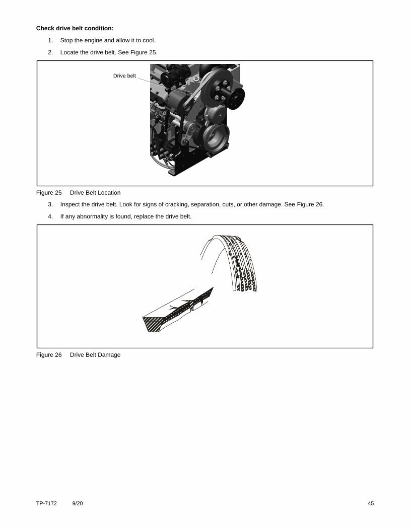
TP-7172 9/20 45
Check drive belt condition:
1. Stop the engine and allow it to cool.
2. Locate the drive belt. See Figure 25.
Figure 25 Drive Belt Location
3. Inspect the drive belt. Look for signs of cracking, separation, cuts, or other damage. See Figure 26.
4. If any abnormality is found, replace the drive belt.
Figure 26 Drive Belt Damage
Drive belt
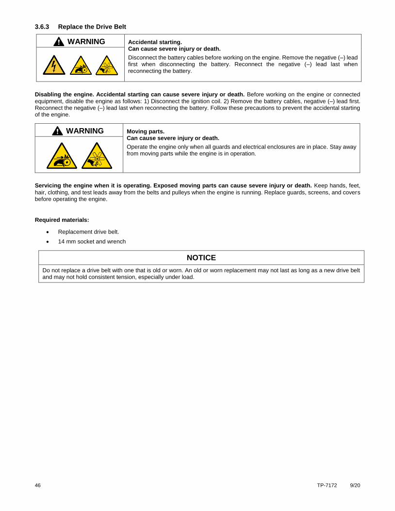
46 TP-7172 9/20
3.6.3 Replace the Drive Belt
WARNING Accidental starting. Can cause severe injury or death.
Disconnect the battery cables before working on the engine. Remove the negative (–) lead first when disconnecting the battery. Reconnect the negative (–) lead last when reconnecting the battery.
Disabling the engine. Accidental starting can cause severe injury or death. Before working on the engine or connected
equipment, disable the engine as follows: 1) Disconnect the ignition coil. 2) Remove the battery cables, negative (–) lead first. Reconnect the negative (–) lead last when reconnecting the battery. Follow these precautions to prevent the accidental starting of the engine.
WARNING Moving parts. Can cause severe injury or death.
Operate the engine only when all guards and electrical enclosures are in place. Stay away from moving parts while the engine is in operation.
Servicing the engine when it is operating. Exposed moving parts can cause severe injury or death. Keep hands, feet,
hair, clothing, and test leads away from the belts and pulleys when the engine is running. Replace guards, screens, and covers before operating the engine.
Required materials:
Replacement drive belt.
14 mm socket and wrench
NOTICE
Do not replace a drive belt with one that is old or worn. An old or worn replacement may not last as long as a new drive belt and may not hold consistent tension, especially under load.
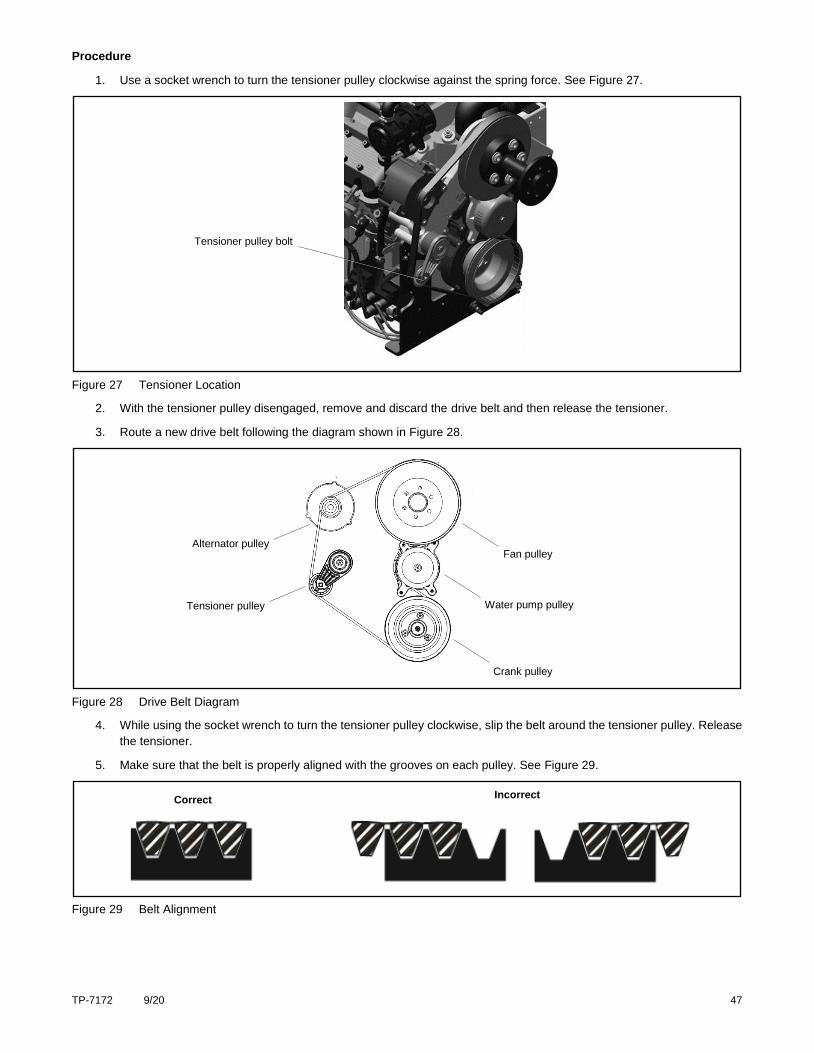
TP-7172 9/20 47
Procedure
1. Use a socket wrench to turn the tensioner pulley clockwise against the spring force. See Figure 27.
Figure 27 Tensioner Location
2. With the tensioner pulley disengaged, remove and discard the drive belt and then release the tensioner.
3. Route a new drive belt following the diagram shown in Figure 28.
Figure 28 Drive Belt Diagram
4. While using the socket wrench to turn the tensioner pulley clockwise, slip the belt around the tensioner pulley. Release
the tensioner.
5. Make sure that the belt is properly aligned with the grooves on each pulley. See Figure 29.
Figure 29 Belt Alignment
Correct Incorrect
Tensioner pulley
Alternator pulley
Water pump pulley
Crank pulley
Fan pulley
Tensioner pulley bolt
48 TP-7172 9/20
3.6.4 Check Wiring and Electrical Connections
CAUTION Hazardous voltage. Electrical shock can cause injury.
Do not touch wires while the engine is running. Stop the engine and disconnect the battery leads, negative (-) lead first, before servicing the engine.
Check the condition of the wiring and electrical connections after every 10 hours of operation. Specific items to look for are:
Exposed (bare) wires.
Cuts or abrasions in wire insulation.
Loose connections at screw terminals.
Loose, dirty, or cracked electrical connectors.
Melted or scorched wiring, insulation, or connectors.
Repair or replace faulty electrical components before operating the machine.
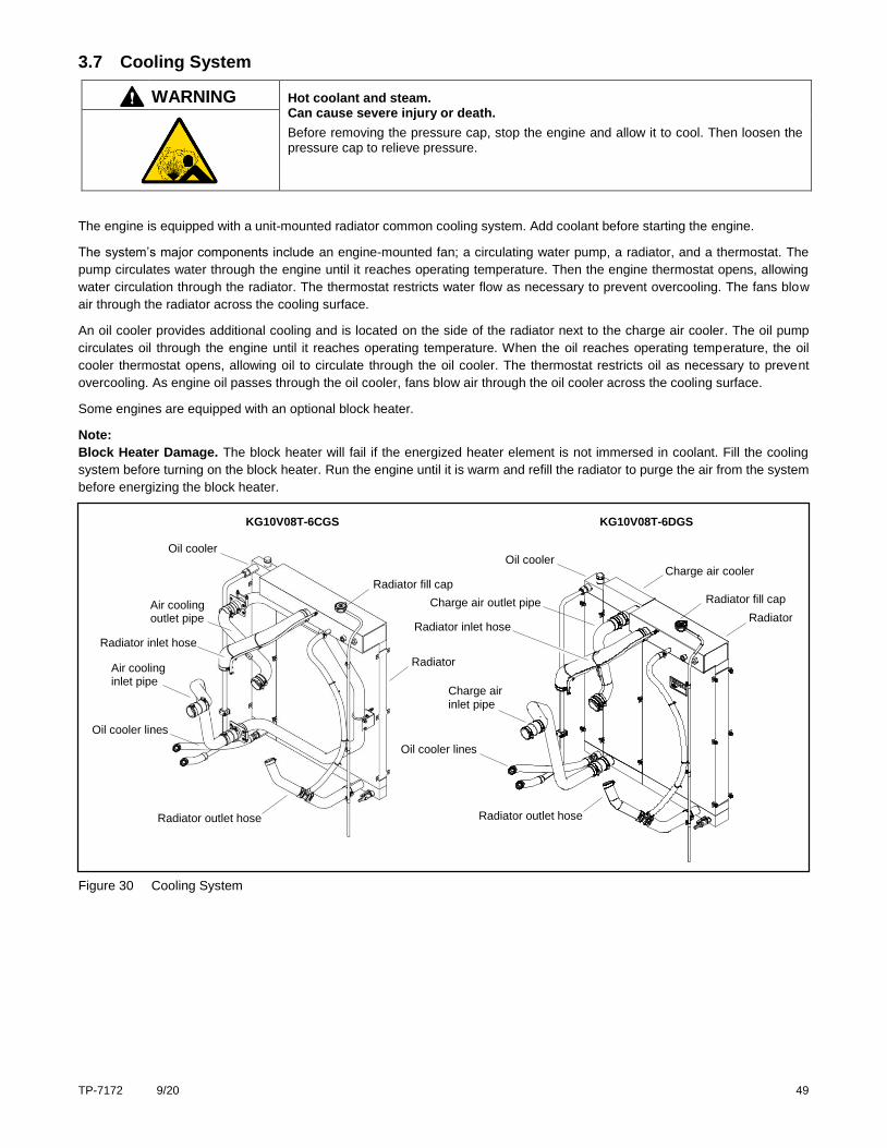
TP-7172 9/20 49
3.7 Cooling System
WARNING Hot coolant and steam. Can cause severe injury or death.
Before removing the pressure cap, stop the engine and allow it to cool. Then loosen the pressure cap to relieve pressure.
The engine is equipped with a unit-mounted radiator common cooling system. Add coolant before starting the engine.
The system’s major components include an engine-mounted fan; a circulating water pump, a radiator, and a thermostat. The
pump circulates water through the engine until it reaches operating temperature. Then the engine thermostat opens, allowing
water circulation through the radiator. The thermostat restricts water flow as necessary to prevent overcooling. The fans blow
air through the radiator across the cooling surface.
An oil cooler provides additional cooling and is located on the side of the radiator next to the charge air cooler. The oil pump
circulates oil through the engine until it reaches operating temperature. When the oil reaches operating temperature, the oil
cooler thermostat opens, allowing oil to circulate through the oil cooler. The thermostat restricts oil as necessary to prevent
overcooling. As engine oil passes through the oil cooler, fans blow air through the oil cooler across the cooling surface.
Some engines are equipped with an optional block heater.
Note:
Block Heater Damage. The block heater will fail if the energized heater element is not immersed in coolant. Fill the cooling
system before turning on the block heater. Run the engine until it is warm and refill the radiator to purge the air from the system
before energizing the block heater.
Figure 30 Cooling System
Charge air cooler
Radiator
Oil cooler
Charge air inlet pipe
Radiator inlet hose
Oil cooler lines
Charge air outlet pipe
Radiator outlet hose
Radiator fill cap
Radiator
Oil cooler
Air cooling inlet pipe
Radiator inlet hose
Oil cooler lines
Air cooling outlet pipe
Radiator outlet hose
Radiator fill cap
KG10V08T-6CGS KG10V08T-6DGS
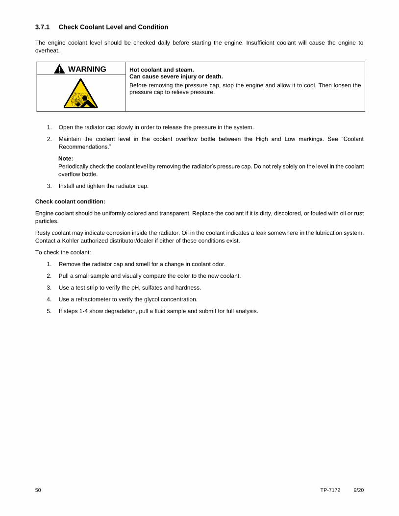
50 TP-7172 9/20
3.7.1 Check Coolant Level and Condition
The engine coolant level should be checked daily before starting the engine. Insufficient coolant will cause the engine to
overheat.
WARNING Hot coolant and steam. Can cause severe injury or death.
Before removing the pressure cap, stop the engine and allow it to cool. Then loosen the pressure cap to relieve pressure.
1. Open the radiator cap slowly in order to release the pressure in the system.
2. Maintain the coolant level in the coolant overflow bottle between the High and Low markings. See “Coolant
Recommendations.”
Note:
Periodically check the coolant level by removing the radiator’s pressure cap. Do not rely solely on the level in the coolant
overflow bottle.
3. Install and tighten the radiator cap.
Check coolant condition:
Engine coolant should be uniformly colored and transparent. Replace the coolant if it is dirty, discolored, or fouled with oil or rust
particles.
Rusty coolant may indicate corrosion inside the radiator. Oil in the coolant indicates a leak somewhere in the lubrication system.
Contact a Kohler authorized distributor/dealer if either of these conditions exist.
To check the coolant:
1. Remove the radiator cap and smell for a change in coolant odor.
2. Pull a small sample and visually compare the color to the new coolant.
3. Use a test strip to verify the pH, sulfates and hardness.
4. Use a refractometer to verify the glycol concentration.
5. If steps 1-4 show degradation, pull a fluid sample and submit for full analysis.
TP-7172 9/20 51
3.7.2 Check Hoses and Clamps
Check the tightness of the hose clamps, oil cooler couplings, and charge air cooler couplings daily. Check the condition of the
cooling system hoses and clamps every 10 hours of operation.
Hoses:
Inspect the hoses for cracks, abrasions, cuts, bulges, swollen ends, or leaks.
Squeeze the hoses. They should yield slightly to moderate pressure and not feel too hard, too soft, or spongy.
Replace faulty hoses before operating the engine.
Clamps:
Verify that all clamps are in place.
Adjust and tighten clamps as needed.
3.7.3 Draining and Replacing the Coolant
There are no coolant plugs or drainage valves on the engine. To drain and replace the coolant, refer to the radiator procedures
in the Maintenance Manual for the equipment using this engine.
52 TP-7172 9/20
3.8 Fuel System
WARNING Explosive fuel vapors. Can cause fires and severe burns.
If a gaseous odor is detected, ventilate the area and contact an authorized service technician.
The fuel system. Explosive fuel vapors can cause severe injury or death. Vaporized fuels are highly explosive. Use extreme
care when handling and storing fuels. Store fuels in a well-ventilated area away from spark-producing equipment and out of the reach of children. Never add fuel to the tank while the engine is running because spilled fuel may ignite on contact with hot parts or from sparks. Do not smoke or permit flames or sparks to occur near sources of spilled fuel or fuel vapors. Keep the fuel lines and connections tight and in good condition. Do not replace flexible fuel lines with rigid lines. Use flexible sections to avoid fuel line breakage caused by vibration. Do not operate the engine in the presence of fuel leaks, fuel accumulation, or sparks. Repair fuel systems before resuming engine operation.
Note:
Fuel system components are not adjustable and cannot be serviced. Contact your authorized KOHLER authorized
distributor/dealer for replacements.
3.8.1 Check Fuel Supply Pipe and Connections
With the fuel valve fully opened and the engine stopped, check all fuel system connections and lines for leaks using a soapy
water solution. Correct any leaks before restarting the engine. Do not start the engine if you can smell leaking gas. Have
any necessary service performed by a Kohler authorized distributor/dealer.
3.8.2 Check Fuel Level (LPG only)
With the fuel valve on the LPG tank fully closed and the engine stopped, check the fuel gauge on the LPG tank. Make sure that
the tank contains enough fuel for sustained operation. If not, refill the tank before restarting the engine.
Fully open the fuel valve on the LPG tank. Check all fuel supply connections and lines for leaks using a soapy water solution.
Correct any leaks before restarting the engine. Have any necessary service performed by a Kohler authorized distributor/dealer
or qualified LPG/NG technician only.
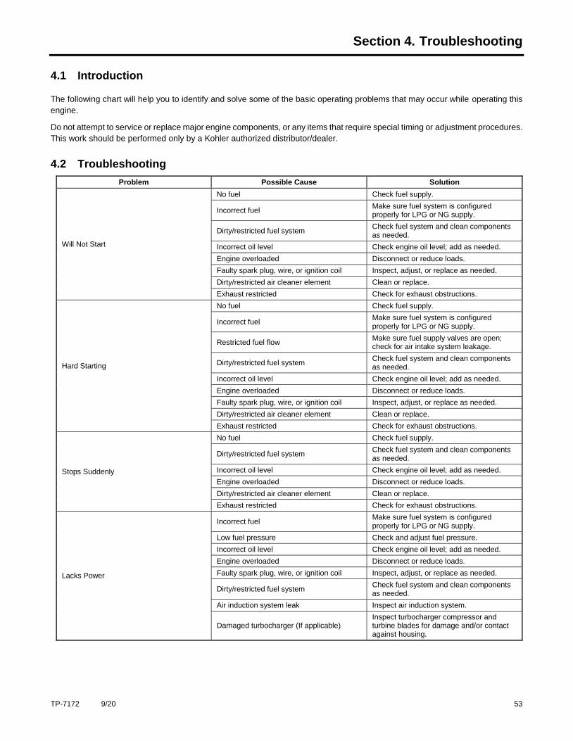
TP-7172 9/20 53
Section 4. Troubleshooting
4.1 Introduction
The following chart will help you to identify and solve some of the basic operating problems that may occur while operating this
engine.
Do not attempt to service or replace major engine components, or any items that require special timing or adjustment procedures.
This work should be performed only by a Kohler authorized distributor/dealer.
4.2 Troubleshooting
Problem Possible Cause Solution
Will Not Start
No fuel Check fuel supply.
Incorrect fuel Make sure fuel system is configured properly for LPG or NG supply.
Dirty/restricted fuel system Check fuel system and clean components as needed.
Incorrect oil level Check engine oil level; add as needed.
Engine overloaded Disconnect or reduce loads.
Faulty spark plug, wire, or ignition coil Inspect, adjust, or replace as needed.
Dirty/restricted air cleaner element Clean or replace.
Exhaust restricted Check for exhaust obstructions.
Hard Starting
No fuel Check fuel supply.
Incorrect fuel Make sure fuel system is configured properly for LPG or NG supply.
Restricted fuel flow Make sure fuel supply valves are open; check for air intake system leakage.
Dirty/restricted fuel system Check fuel system and clean components as needed.
Incorrect oil level Check engine oil level; add as needed.
Engine overloaded Disconnect or reduce loads.
Faulty spark plug, wire, or ignition coil Inspect, adjust, or replace as needed.
Dirty/restricted air cleaner element Clean or replace.
Exhaust restricted Check for exhaust obstructions.
Stops Suddenly
No fuel Check fuel supply.
Dirty/restricted fuel system Check fuel system and clean components as needed.
Incorrect oil level Check engine oil level; add as needed.
Engine overloaded Disconnect or reduce loads.
Dirty/restricted air cleaner element Clean or replace.
Exhaust restricted Check for exhaust obstructions.
Lacks Power
Incorrect fuel Make sure fuel system is configured properly for LPG or NG supply.
Low fuel pressure Check and adjust fuel pressure.
Incorrect oil level Check engine oil level; add as needed.
Engine overloaded Disconnect or reduce loads.
Faulty spark plug, wire, or ignition coil Inspect, adjust, or replace as needed.
Dirty/restricted fuel system Check fuel system and clean components as needed.
Air induction system leak Inspect air induction system.
Damaged turbocharger (If applicable) Inspect turbocharger compressor and turbine blades for damage and/or contact against housing.
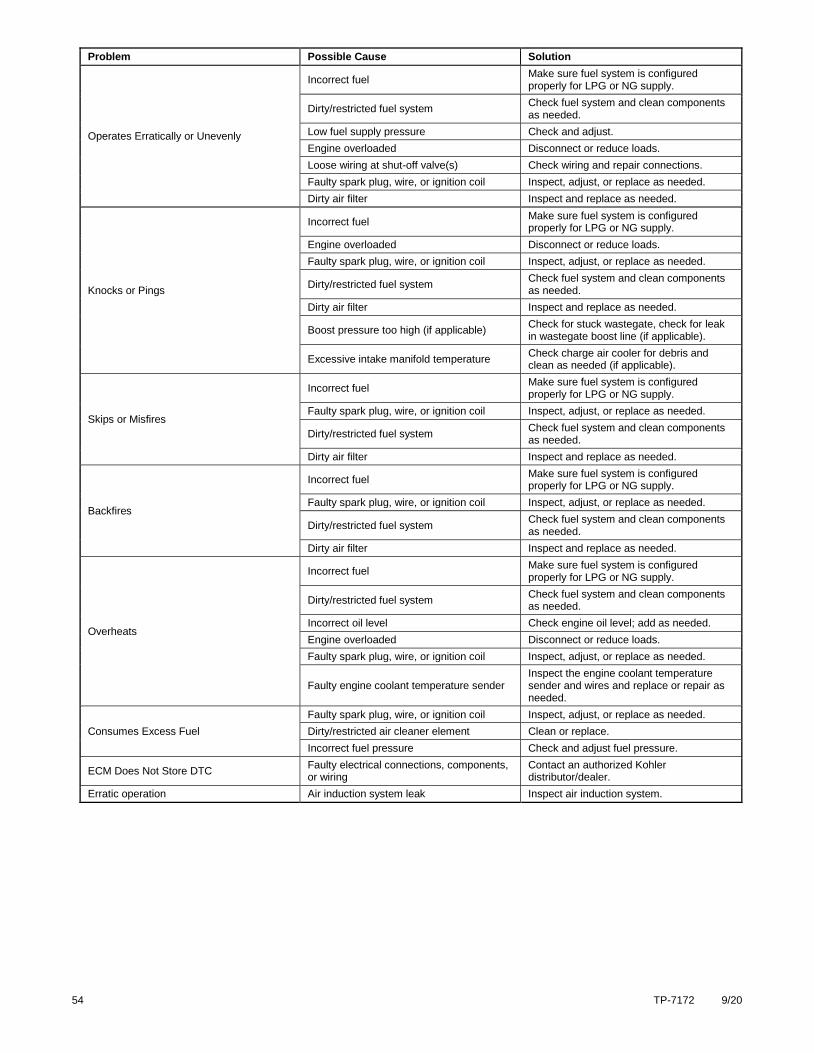
54 TP-7172 9/20
Problem Possible Cause Solution
Operates Erratically or Unevenly
Incorrect fuel Make sure fuel system is configured properly for LPG or NG supply.
Dirty/restricted fuel system Check fuel system and clean components as needed.
Low fuel supply pressure Check and adjust.
Engine overloaded Disconnect or reduce loads.
Loose wiring at shut-off valve(s) Check wiring and repair connections.
Faulty spark plug, wire, or ignition coil Inspect, adjust, or replace as needed.
Dirty air filter Inspect and replace as needed.
Knocks or Pings
Incorrect fuel Make sure fuel system is configured properly for LPG or NG supply.
Engine overloaded Disconnect or reduce loads.
Faulty spark plug, wire, or ignition coil Inspect, adjust, or replace as needed.
Dirty/restricted fuel system Check fuel system and clean components as needed.
Dirty air filter Inspect and replace as needed.
Boost pressure too high (if applicable) Check for stuck wastegate, check for leak in wastegate boost line (if applicable).
Excessive intake manifold temperature Check charge air cooler for debris and clean as needed (if applicable).
Skips or Misfires
Incorrect fuel Make sure fuel system is configured properly for LPG or NG supply.
Faulty spark plug, wire, or ignition coil Inspect, adjust, or replace as needed.
Dirty/restricted fuel system Check fuel system and clean components as needed.
Dirty air filter Inspect and replace as needed.
Backfires
Incorrect fuel Make sure fuel system is configured properly for LPG or NG supply.
Faulty spark plug, wire, or ignition coil Inspect, adjust, or replace as needed.
Dirty/restricted fuel system Check fuel system and clean components as needed.
Dirty air filter Inspect and replace as needed.
Overheats
Incorrect fuel Make sure fuel system is configured properly for LPG or NG supply.
Dirty/restricted fuel system Check fuel system and clean components as needed.
Incorrect oil level Check engine oil level; add as needed.
Engine overloaded Disconnect or reduce loads.
Faulty spark plug, wire, or ignition coil Inspect, adjust, or replace as needed.
Faulty engine coolant temperature sender Inspect the engine coolant temperature sender and wires and replace or repair as needed.
Consumes Excess Fuel
Faulty spark plug, wire, or ignition coil Inspect, adjust, or replace as needed.
Dirty/restricted air cleaner element Clean or replace.
Incorrect fuel pressure Check and adjust fuel pressure.
ECM Does Not Store DTC Faulty electrical connections, components, or wiring
Contact an authorized Kohler distributor/dealer.
Erratic operation Air induction system leak Inspect air induction system.
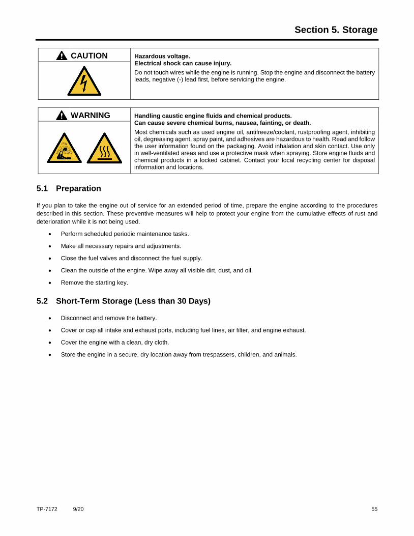
TP-7172 9/20 55
Section 5. Storage
CAUTION Hazardous voltage. Electrical shock can cause injury.
Do not touch wires while the engine is running. Stop the engine and disconnect the battery leads, negative (-) lead first, before servicing the engine.
WARNING Handling caustic engine fluids and chemical products. Can cause severe chemical burns, nausea, fainting, or death.
Most chemicals such as used engine oil, antifreeze/coolant, rustproofing agent, inhibiting oil, degreasing agent, spray paint, and adhesives are hazardous to health. Read and follow the user information found on the packaging. Avoid inhalation and skin contact. Use only in well-ventilated areas and use a protective mask when spraying. Store engine fluids and chemical products in a locked cabinet. Contact your local recycling center for disposal information and locations.
5.1 Preparation
If you plan to take the engine out of service for an extended period of time, prepare the engine according to the procedures
described in this section. These preventive measures will help to protect your engine from the cumulative effects of rust and
deterioration while it is not being used.
Perform scheduled periodic maintenance tasks.
Make all necessary repairs and adjustments.
Close the fuel valves and disconnect the fuel supply.
Clean the outside of the engine. Wipe away all visible dirt, dust, and oil.
Remove the starting key.
5.2 Short-Term Storage (Less than 30 Days)
Disconnect and remove the battery.
Cover or cap all intake and exhaust ports, including fuel lines, air filter, and engine exhaust.
Cover the engine with a clean, dry cloth.
Store the engine in a secure, dry location away from trespassers, children, and animals.
56 TP-7172 9/20
5.3 Long-Term Storage (More than 30 Days)
In addition to the short-term tasks, perform the following tasks before placing the engine in storage:
Change the engine oil and filter.
Remove the drive belt.
Protect the cylinders from rust:
o Disconnect the spark plug wires and remove the spark plugs.
o Squirt approximately 30 ml (1 ounce) of fresh engine oil into each cylinder.
o Manually rotate the crankshaft 10–15 times to distribute the oil evenly in the cylinders.
o Install the spark plugs and reconnect the spark plug wires.
Cover all exposed metal parts with a suitable protectant.
Coat all electrical connectors with a suitable protectant.
5.4 Maintenance while in Storage
Inspect the engine regularly (at least once a month). Check for signs of rust or leaks.
Periodically test the battery voltage and recharge as needed. The battery may lose charge even when disconnected.
5.5 Removal from Storage
Remove protective cloths, covers, and caps from the engine.
Clean protectant from exposed metal parts and electrical components.
Reinstall the drive belt.
Check fluid levels and fill as needed.
Connect the battery.
Connect the fuel supply and open fuel valves.
Start the engine and allow it to run for several minutes without load. Check for leaks and watch for signs of abnormal
operation.
NOTE:
The engine may smoke when started for the first time after being taken out of storage. This is normal and occurs as
the engine burns away the protective oil coating inside the cylinders.
Check oil pressure and fuel pressure gauges to make sure that the engine is operating normally.
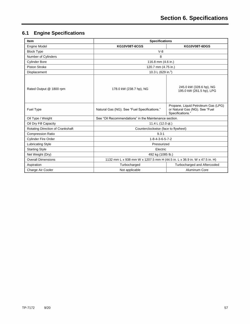
TP-7172 9/20 57
Section 6. Specifications
6.1 Engine Specifications
Item Specifications
Engine Model KG10V08T-6CGS KG10V08T-6DGS
Block Type V-8
Number of Cylinders 8
Cylinder Bore 116.8 mm (4.6 in.)
Piston Stroke 120.7 mm (4.75 in.)
Displacement 10.3 L (629 in.3)
Rated Output @ 1800 rpm 178.0 kW (238.7 hp), NG 245.0 kW (328.6 hp), NG 195.0 kW (261.5 hp), LPG
Fuel Type Natural Gas (NG). See “Fuel Specifications.” Propane, Liquid Petroleum Gas (LPG) or Natural Gas (NG). See “Fuel Specifications.”
Oil Type / Weight See “Oil Recommendations” in the Maintenance section.
Oil Dry Fill Capacity 11.4 L (12.0 qt.)
Rotating Direction of Crankshaft Counterclockwise (face to flywheel)
Compression Ratio 9.3:1
Cylinder Fire Order 1-8-4-3-6-5-7-2
Lubricating Style Pressurized
Starting Style Electric
Net Weight (Dry) 492 kg (1085 lb.)
Overall Dimensions 1132 mm L x 938 mm W x 1207.5 mm H (44.5 in. L x 36.9 in. W x 47.5 in. H)
Aspiration Turbocharged Turbocharged and Aftercooled
Charge Air Cooler Not applicable Aluminum Core
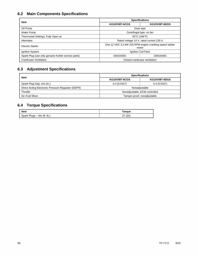
58 TP-7172 9/20
6.2 Main Components Specifications
Item Specifications
KG10V08T-6CGS KG10V08T-6DGS
Oil Pump Gear type
Water Pump Centrifugal type; no fan
Thermostat Settings, Fully Open at 93°C (199°F)
Alternator Rated voltage 14 V, rated current 130 A
Electric Starter One 12 VDC 3.2 kW 225 RPM engine cranking speed starter
motor
Ignition System Ignition Coil Pack
Spark Plug (use only genuine Kohler service parts) GM104391 GM104391
Crankcase Ventilation Closed crankcase ventilation
6.3 Adjustment Specifications
Item Specifications
KG10V08T-6CGS KG10V08T-6DGS
Spark Plug Gap, mm (in.) 0.4 (0.0157) 0.4 (0.0157)
Direct Acting Electronic Pressure Regulator (DEPR) Nonadjustable
Throttle Nonadjustable, ECM controlled
Air–Fuel Mixer Tamper-proof; nonadjustable
6.4 Torque Specifications
Item Torque
Spark Plugs – Nm (ft. lb.) 27 (20)
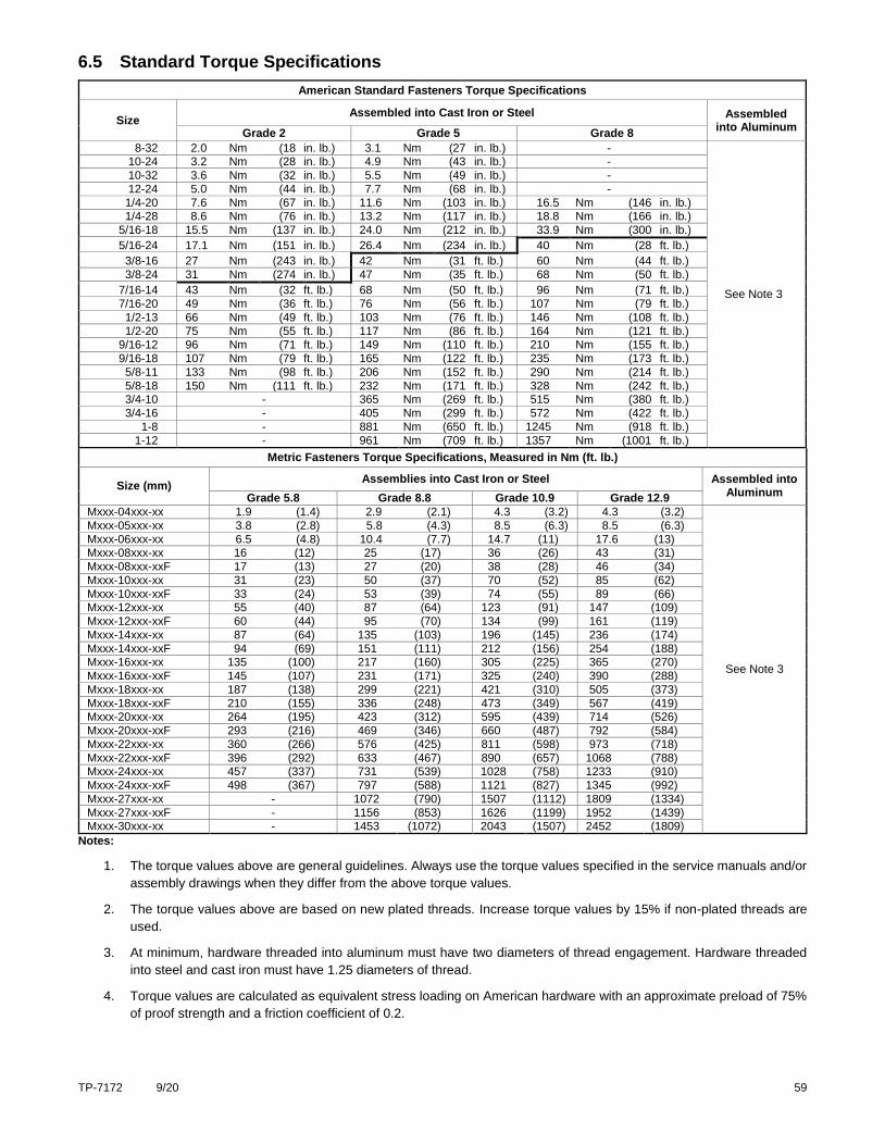
TP-7172 9/20 59
6.5 Standard Torque Specifications
American Standard Fasteners Torque Specifications
Size Assembled into Cast Iron or Steel Assembled
into Aluminum Grade 2 Grade 5 Grade 8
8-32 2.0 Nm (18 in. lb.) 3.1 Nm (27 in. lb.) -
See Note 3
10-24 3.2 Nm (28 in. lb.) 4.9 Nm (43 in. lb.) -
10-32 3.6 Nm (32 in. lb.) 5.5 Nm (49 in. lb.) -
12-24 5.0 Nm (44 in. lb.) 7.7 Nm (68 in. lb.) -
1/4-20 7.6 Nm (67 in. lb.) 11.6 Nm (103 in. lb.) 16.5 Nm (146 in. lb.) 1/4-28 8.6 Nm (76 in. lb.) 13.2 Nm (117 in. lb.) 18.8 Nm (166 in. lb.)
5/16-18 15.5 Nm (137 in. lb.) 24.0 Nm (212 in. lb.) 33.9 Nm (300 in. lb.)
5/16-24 17.1 Nm (151 in. lb.) 26.4 Nm (234 in. lb.) 40 Nm (28 ft. lb.)
3/8-16 27 Nm (243 in. lb.) 42 Nm (31 ft. lb.) 60 Nm (44 ft. lb.)
3/8-24 31 Nm (274 in. lb.) 47 Nm (35 ft. lb.) 68 Nm (50 ft. lb.)
7/16-14 43 Nm (32 ft. lb.) 68 Nm (50 ft. lb.) 96 Nm (71 ft. lb.)
7/16-20 49 Nm (36 ft. lb.) 76 Nm (56 ft. lb.) 107 Nm (79 ft. lb.)
1/2-13 66 Nm (49 ft. lb.) 103 Nm (76 ft. lb.) 146 Nm (108 ft. lb.)
1/2-20 75 Nm (55 ft. lb.) 117 Nm (86 ft. lb.) 164 Nm (121 ft. lb.) 9/16-12 96 Nm (71 ft. lb.) 149 Nm (110 ft. lb.) 210 Nm (155 ft. lb.)
9/16-18 107 Nm (79 ft. lb.) 165 Nm (122 ft. lb.) 235 Nm (173 ft. lb.)
5/8-11 133 Nm (98 ft. lb.) 206 Nm (152 ft. lb.) 290 Nm (214 ft. lb.)
5/8-18 150 Nm (111 ft. lb.) 232 Nm (171 ft. lb.) 328 Nm (242 ft. lb.) 3/4-10 - 365 Nm (269 ft. lb.) 515 Nm (380 ft. lb.)
3/4-16 - 405 Nm (299 ft. lb.) 572 Nm (422 ft. lb.)
1-8 - 881 Nm (650 ft. lb.) 1245 Nm (918 ft. lb.)
1-12 - 961 Nm (709 ft. lb.) 1357 Nm (1001 ft. lb.)
Metric Fasteners Torque Specifications, Measured in Nm (ft. lb.)
Size (mm) Assemblies into Cast Iron or Steel Assembled into
Aluminum Grade 5.8 Grade 8.8 Grade 10.9 Grade 12.9
Mxxx-04xxx-xx 1.9 (1.4) 2.9 (2.1) 4.3 (3.2) 4.3 (3.2)
See Note 3
Mxxx-05xxx-xx 3.8 (2.8) 5.8 (4.3) 8.5 (6.3) 8.5 (6.3)
Mxxx-06xxx-xx 6.5 (4.8) 10.4 (7.7) 14.7 (11) 17.6 (13) Mxxx-08xxx-xx 16 (12) 25 (17) 36 (26) 43 (31)
Mxxx-08xxx-xxF 17 (13) 27 (20) 38 (28) 46 (34)
Mxxx-10xxx-xx 31 (23) 50 (37) 70 (52) 85 (62)
Mxxx-10xxx-xxF 33 (24) 53 (39) 74 (55) 89 (66) Mxxx-12xxx-xx 55 (40) 87 (64) 123 (91) 147 (109)
Mxxx-12xxx-xxF 60 (44) 95 (70) 134 (99) 161 (119)
Mxxx-14xxx-xx 87 (64) 135 (103) 196 (145) 236 (174)
Mxxx-14xxx-xxF 94 (69) 151 (111) 212 (156) 254 (188) Mxxx-16xxx-xx 135 (100) 217 (160) 305 (225) 365 (270)
Mxxx-16xxx-xxF 145 (107) 231 (171) 325 (240) 390 (288)
Mxxx-18xxx-xx 187 (138) 299 (221) 421 (310) 505 (373)
Mxxx-18xxx-xxF 210 (155) 336 (248) 473 (349) 567 (419) Mxxx-20xxx-xx 264 (195) 423 (312) 595 (439) 714 (526)
Mxxx-20xxx-xxF 293 (216) 469 (346) 660 (487) 792 (584)
Mxxx-22xxx-xx 360 (266) 576 (425) 811 (598) 973 (718)
Mxxx-22xxx-xxF 396 (292) 633 (467) 890 (657) 1068 (788) Mxxx-24xxx-xx 457 (337) 731 (539) 1028 (758) 1233 (910)
Mxxx-24xxx-xxF 498 (367) 797 (588) 1121 (827) 1345 (992)
Mxxx-27xxx-xx - 1072 (790) 1507 (1112) 1809 (1334)
Mxxx-27xxx-xxF - 1156 (853) 1626 (1199) 1952 (1439) Mxxx-30xxx-xx - 1453 (1072) 2043 (1507) 2452 (1809)
Notes:
1. The torque values above are general guidelines. Always use the torque values specified in the service manuals and/or
assembly drawings when they differ from the above torque values.
2. The torque values above are based on new plated threads. Increase torque values by 15% if non-plated threads are
used.
3. At minimum, hardware threaded into aluminum must have two diameters of thread engagement. Hardware threaded
into steel and cast iron must have 1.25 diameters of thread.
4. Torque values are calculated as equivalent stress loading on American hardware with an approximate preload of 75%
of proof strength and a friction coefficient of 0.2.

60 TP-7172 9/20

TP-7172 9/20 61

62 TP-7172 9/20


TP-7172 9/20
Original Instructions (English)
© 2020 Kohler Co. All rights reserved.
KOHLER CO. Kohler, Wisconsin 53044 Phone 920-457-4441, Fax 920-459-1646 For the nearest sales/service outlet in the US and Canada, phone 1-800-544-2444 KOHLERPower.com