Embed Size (px)
Citation preview
CS-TM-014.02 Revised 09/25/18
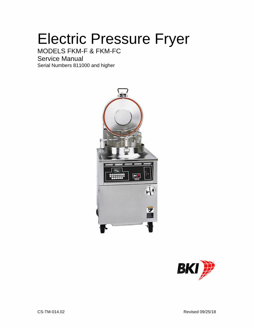
Electric Pressure Fryer MODELS FKM-F & FKM-FC Service Manual Serial Numbers 811000 and higher


BKI LIMITED WARRANTY 2812 Grandview Dr. • Simpsonville, SC 29680 • USA
(864) 963-3471 • Toll Free: (800) 927-6887 • Fax: (864) 963-5316
WHAT IS COVERED This warranty covers defects in material and workmanship under normal use, and applies only to the
original purchaser providing that: The equipment has not been accidentally or intentionally damaged, altered or misused;
The equipment is properly installed, adjusted, operated and maintained in accordance with national
and local codes, and in accordance with the installation and operating instructions provided with this
product.
The serial number rating plate affixed to the equipment has not been defaced or removed.
WHO IS COVERED This warranty is extended to the original purchaser and applies only to equipment purchased for use in the U.S.A.
COVERAGE PERIOD Warranty claims must be received in writing by BKI within one (1) year from date of
installation or within one (1) year and three (3) months from data of shipment from the
factory, whichever comes first.
COB Models: One (1) Year limited parts and labor.
COM Models: Two (2) Year limited parts and labor. COM convection ovens also have a two (2)
year door warranty.
CO1 Models: Two (2) Year limited parts and labor. Five (5) Year limited door warranty.
Warranty period begins the date of dealer invoice to customer or ninety (90) days after
shipment date from BKI, whichever comes first.
WARRANTY COVERAGE This warranty covers on-site labor, parts and reasonable travel time and travel expenses of the authorized service representative up to (100) miles round trip and (2) hours travel time and performed during regular, weekday business hours.
EXCEPTIONS Any exceptions must be pre-approved in advance and in writing by BKI. The extended door warranty on convection ovens years 3 through 5 is a parts only warranty and does not include labor, travel, mileage or any other charges.
EXCLUSIONS Negligence or acts of God, Thermostat calibrations after (30) days from equipment installation date, Air and gas adjustments, Light bulbs,
Glass doors and door adjustments, Fuses, Adjustments to burner flames and cleaning of pilot burners, Tightening of screws or fasteners,
Failures caused by erratic voltages or gas suppliers, Unauthorized repair by anyone other than a BKI Factory Authorized Service Center, Damage in shipment, Alteration, misuse or improper installation,
Thermostats and safety valves with broken capillary tubes, Freight – other than normal UPS charges, Ordinary wear and tear, Failure to follow installation and/or operating instructions,
Events beyond control of the company.
INSTALLATION Leveling, as well as proper installation and check out of all new equipment - per appropriate installation and use materials – is the responsibility of the dealer or installer, not the manufacturer.
REPLACEMENT PARTS BKI genuine Factory OEM parts receive a (90) day materials warranty effective from the date of installation by a BKI Factory Authorized Service Center.
Warranty is in lieu of all other warranties, expressed or implied, and all other obligations or liabilities on the manufacturer’s part. BKI shall in no event be liable for any special, indirect or consequential damages, or in any event for damages in excess of the purchase price of the unit. The repair or replacement of proven defective parts shall constitute a fulfillment of all obligations under the terms of this warranty.
Electric Pressure Fryer Table of Contents
1
Table of Contents
Table of Contents ........................................................................................................................................ 1
Introduction ................................................................................................................................................. 2 Safety Precautions .................................................................................................................................... 2
Safety Signs and Messages ................................................................................................................. 2 Specific Precautions ............................................................................................................................. 3
Equipotential ground plane .............................................................................................................. 3 Full Disconnection ............................................................................................................................ 3
Safe Work Practices ............................................................................................................................. 4
Installation ................................................................................................................................................... 9
Operation ................................................................................................................................................... 10 Controls and Indicators ........................................................................................................................... 10 Care of the Shortening ............................................................................................................................ 12 FKM-F Operation .................................................................................................................................... 13
System Programming ......................................................................................................................... 13 Product Programming ........................................................................................................................ 15 Start-Up (FKM-F) ................................................................................................................................ 16 Cooking (FKM-F) ................................................................................................................................ 17
FKM-FC Operation ................................................................................................................................. 19 System Programming ......................................................................................................................... 19 Product Programming ........................................................................................................................ 22 Start-Up (FKM-FC) ............................................................................................................................. 25 Cooking (FKM-FC) ............................................................................................................................. 26
Maintenance .............................................................................................................................................. 28 Scheduled Maintenance ......................................................................................................................... 28
Safety Pop Valve Procedure .............................................................................................................. 29 Troubleshooting ...................................................................................................................................... 30
Filter Pump Reset: .............................................................................................................................. 30
Replacement Parts .................................................................................................................................... 31 Assemblies .............................................................................................................................................. 31 Components............................................................................................................................................ 49 Accessories ............................................................................................................................................. 51
Wiring Diagrams ........................................................................................................................................ 53
Notes .......................................................................................................................................................... 59
BKI Worldwide is a wholly owned subsidiary of Standex International Corporation
Electric Pressure Fryer Introduction
2
Introduction The FKM Pressure Fryer is compact, attractive and functional in design. It is constructed of a stainless steel fryer pot for cleaning ease. Exclusive BKI patented features and safety devices offer flexibility, efficiency and reliability plus PERFECTION IN PRESSURE FRYING!
The BKI name and trademark on this unit assures you of the finest in design and engineering -- that it has been built with care and dedication -- using the best materials available. Attention to the operating instructions regarding proper installation, operation, and maintenance will result in long lasting dependability to insure the highest profitable return on your investment.
PLEASE READ THIS ENTIRE MANUAL BEFORE OPERATING THE UNIT. If you have any questions, please contact your BKI Distributor. If they are unable to answer your questions, contact the BKI Technical Service Department, toll free: 1-800-927-6887. Outside the U.S., call 1-864-963-3471.
Safety Precautions Always follow recommended safety precautions listed in this manual. Below is the safety alert symbol. When you see this symbol on your equipment, be alert to the potential for personal injury or property damage.
Safety Signs and Messages The following Safety signs and messages are placed in this manual to provide instructions and identify specific areas where potential hazards exist and special precautions should be taken. Know and understand the meaning of these instructions, signs, and messages. Damage to the equipment, death or serious injury to you or other persons may result if these messages are not followed.
This message indicates an imminently hazardous situation which, if not avoided, will result in death or serious injury.
This message indicates a potentially hazardous situation, which, if not avoided, could result in death or serious injury.
This message indicates a potentially hazardous situation, which, if not avoided, may result in minor or moderate injury. It may also be used to alert against unsafe practices.
This message is used when special information, instructions or identification are required relating to procedures, equipment, tools, capacities and other special data.

Electric Pressure Fryer Introduction
3
Specific Precautions
Risk of fire exists if the oil level drops below 5mm of the maximum oil level.
Use of oil/shortening older than the manufacturers recommendations for life of the oil is prone to surge boiling and flash fires. Follow the oil manufacturers guidelines for the life cycle of oil/shortening.
Do not open the drain valve or the fill valve while the fryer is under pressure. Serious burns may result.
Improper installation, adjustment, alteration, service or maintenance can cause property damage, injury or death. Read the installation, operation and maintenance instructions thoroughly before installing or servicing this equipment.
California Residents Only
This product can expose you to chemicals including chromium, and lead which
are known to the State of California to cause cancer and birth defects or other
reproductive harm. For more information go to www.P65Warnings.ca.gov.
Follow instructions regarding effects of surge boiling of over-wet foods and proper load size.
Equipotential ground plane When a high current flows through a conductor, differences in potential appear between the conductor and nearby metallic surfaces near the appliance. As a result, sparks may be produced between the appliance and surrounding metal surfaces. These sparks could cause serious injury, damage, or fire. BKI provides an Equipotential ground terminal for the connection of a bonding conductor after the installation of the appliance per lEC60417-1. This terminal is located on the inside of the Power Entry Supply box near the Earth connection and is marked with this symbol.
Full Disconnection In accordance with Local and/or National wiring codes, the installer must provide a means of full disconnection under over voltage Category III conditions. An IEC approved cord and plug combination will meet this requirement. Units not provided with a cord and plug do not meet this requirement. In accordance with Local and/or National wiring codes, the installer must provide the means of full disconnection.
The fryer is designed to hold a maximum of 75lbs (34KG) of oil/shortening.

Electric Pressure Fryer Introduction
4
Safe Work Practices
Beware of High Voltage This equipment uses high voltage. Serious injury can occur if you or any untrained or unauthorized person installs, services, or repairs this equipment. Always Use an Authorized Service agent to Service Your Equipment.
Noncombustible Floors Only Make sure your floor is noncombustible. Do not operate your fryer
on floors that are wood, carpeted or have rubber mats.
• Placing your fryer on a combustible floor could cause a fire. Serious injury could result.
• Examples of noncombustible floors where you can safely place your fryer are concrete, tile, and ceramic.
Keep the Area Around Your Fryer Uncluttered Make sure to keep the area around your fryer clear of any obstacles. Serious injury can occur if you trip or fall near the fryer. You could be burned by hot shortening that splashes out of the fryer or by falling against the hot metal of the fryer.
Keep the Floor Around Your Fryer Clean Of Shortening Make sure to keep the floor around your fryer clean of shortening and other liquids. Serious injury can occur if you slip near your fryer. You could be burned by hot shortening that splashes out of the fryer or by falling against the hot metal of the fryer.

Electric Pressure Fryer Introduction
5
Keep the Lid Closed When The Fryer Is Not In Use Hot shortening can splash if someone moves the fryer or bumps into it. Serious injury can occur if hot shortening splashes out of the fryer. Do not lean, sit or stand on the fryer or perform any maintenance or cleaning duties while the fryer or the shortening is hot. You could be burned.
Keep the Casters Locked To avoid spilling shortening, keep the casters locked. If any shortening spills near your fryer, clean it up immediately. .
Do Not Overfill the Fryer with Shortening Hot shortening and steam may escape and burn you if you put too much shortening in the fryer. Fill the fryer to the fill marks that are inside the fryer pot. Heat the shortening.
Do Not Let Any Water Get into The Fryer Always remove excess moisture from food before placing it into the fryer basket. Water will cause the hot shortening to spatter. You could be burned.
Do Not Overload the Basket With Food Hot shortening and steam may escape and burn you if you place too much food in the basket.
Always Make Sure the Lid Hook Is Latched When Closing The Fryer To make sure the lid hook is latched properly, press down the lid until the hook snaps shut. Hot shortening and steam can escape if the lid hook is not latched properly. You could be burned.
Electric Pressure Fryer Introduction
6
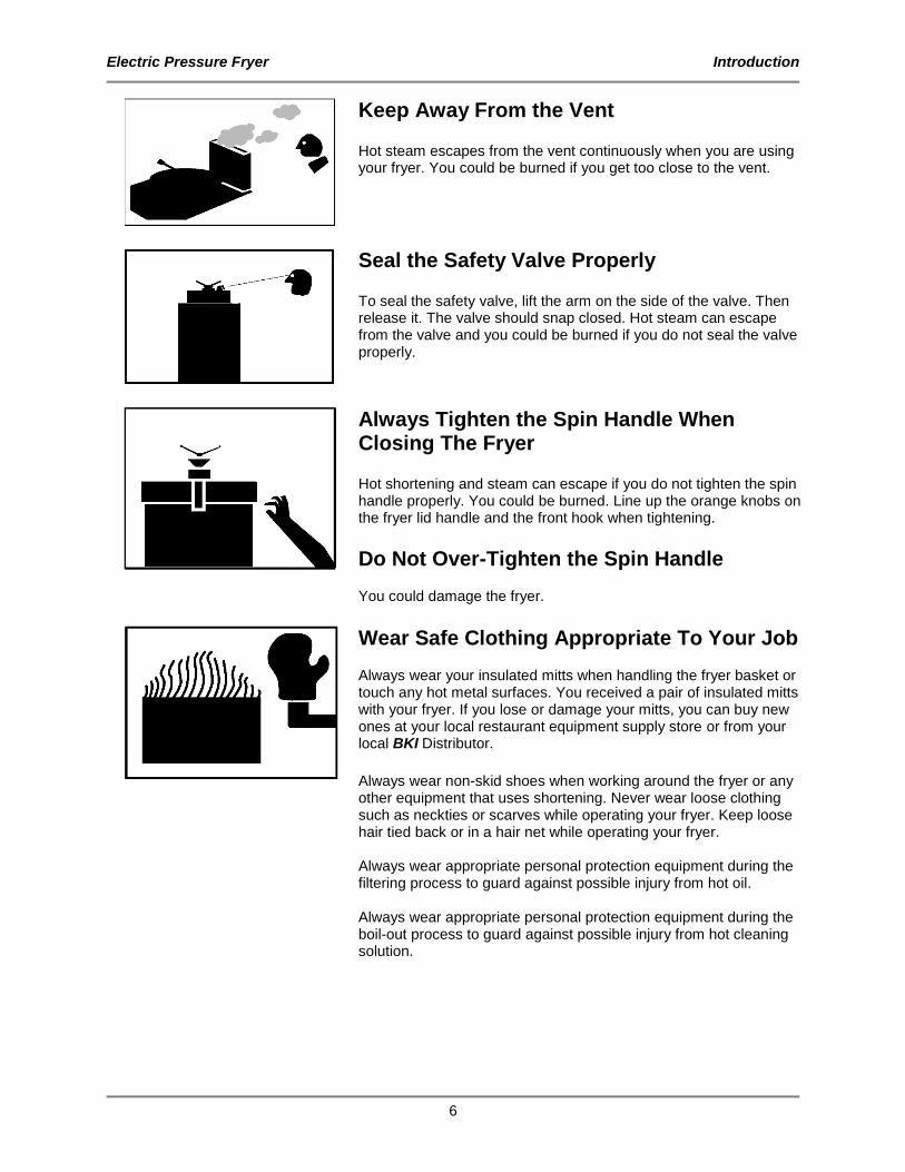
Keep Away From the Vent Hot steam escapes from the vent continuously when you are using your fryer. You could be burned if you get too close to the vent.
Seal the Safety Valve Properly To seal the safety valve, lift the arm on the side of the valve. Then release it. The valve should snap closed. Hot steam can escape from the valve and you could be burned if you do not seal the valve properly.
Always Tighten the Spin Handle When Closing The Fryer Hot shortening and steam can escape if you do not tighten the spin handle properly. You could be burned. Line up the orange knobs on the fryer lid handle and the front hook when tightening.
Do Not Over-Tighten the Spin Handle You could damage the fryer.
Wear Safe Clothing Appropriate To Your Job Always wear your insulated mitts when handling the fryer basket or touch any hot metal surfaces. You received a pair of insulated mitts with your fryer. If you lose or damage your mitts, you can buy new ones at your local restaurant equipment supply store or from your local BKI Distributor.
Always wear non-skid shoes when working around the fryer or any other equipment that uses shortening. Never wear loose clothing such as neckties or scarves while operating your fryer. Keep loose hair tied back or in a hair net while operating your fryer. Always wear appropriate personal protection equipment during the filtering process to guard against possible injury from hot oil. Always wear appropriate personal protection equipment during the boil-out process to guard against possible injury from hot cleaning solution.

Electric Pressure Fryer Introduction
7
Never Loosen the Spin Handle Until The Pressure Gauge Is At Zero Steam may escape suddenly if you loosen the spin handle before the gauge is at zero. If steam escapes suddenly, you could be burned.
After the pressure gauge is at zero, wait 5 seconds. Then loosen the spin handle slowly to open the lid of the fryer. By doing this, the steam will escape slowly and you will not be burned.
Keep this manual with the Equipment This manual is an important part of your equipment. Always keep it near for easy access.
If you need to replace this manual, contact: BKI Technical Services Department 2812 Grandview Drive Simpsonville, S.C. 29680 Or call toll free: 1-800-927-6887 Outside the U.S., call 864-963-3471
Protect Children Keep children away from this equipment. Children may not understand that this equipment is dangerous for them and others. NEVER allow children to play near or operate your equipment.
Keep Safety Labels Clean and in Good Condition Do not remove or cover any safety labels on your equipment. Keep all safety labels clean and in good condition. Replace any damaged or missing safety labels. Refer to the Safety Labels section for illustration and location of safety labels on this unit. If you need a new safety label, obtain the number of the specific label illustrated on page Error! Bookmark not defined., then contact: BKI Technical Services Department 2812 Grandview Drive Simpsonville, S.C. 29680 Or call toll free: 1-800-927-6887 Outside the U.S., call 864-963-3471

Electric Pressure Fryer Introduction
8
Be Prepared for Emergencies Be prepared for fires, injuries, or other emergencies. Keep a first aid kit and a fire extinguisher near the equipment. You must use a 40-pound Type BC fire extinguisher and keep it within 25 feet of your equipment. Keep emergency numbers for doctors, ambulance services, hospitals, and the fire department near your telephone.
Know your responsibilities as an Employer
• Make certain your employees know how to operate the equipment.
• Make certain your employees are aware of the safety precautions on the equipment and in this manual.
• Make certain that you have thoroughly trained your employees about operating the equipment safely.
• Make certain the equipment is in proper working condition. If you make unauthorized modifications to the equipment, you will reduce the function and safety of the equipment.

Electric Pressure Fryer Installation
9
Installation For installation information refer to Electric Pressure Fryer, MODELS FKM-F & FKM-FC, Installation and Operation Manual.

Electric Pressure Fryer Operation
10
Operation
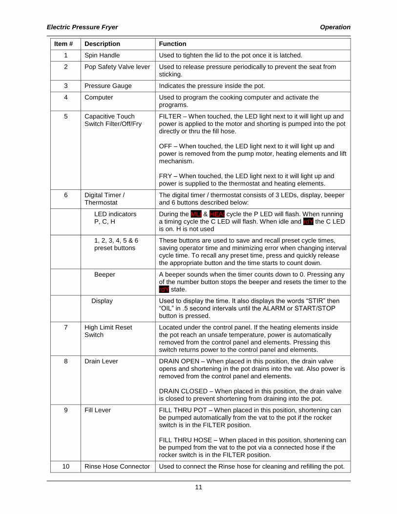
Controls and Indicators Refer to the figure and table below for an explanation of the fryer’s controls and indicators.
FILTER
OFF
FRY
Pressure FryerFKM-FCSCANPROG
TEMP
ENTER TOGGLECLEAR
1
IDLE
09
HOLD
2 3 4 5 6 7 8
BOIL
OUT
N0688N0688N0688
R
FILTER
OFF
FRY
N0684
R
Pressure FryerFKM-F
Electric Pressure Fryer Operation
11
Item # Description Function
1 Spin Handle Used to tighten the lid to the pot once it is latched.
2 Pop Safety Valve lever Used to release pressure periodically to prevent the seat from sticking.
3 Pressure Gauge Indicates the pressure inside the pot.
4 Computer Used to program the cooking computer and activate the programs.
5 Capacitive Touch Switch Filter/Off/Fry
FILTER – When touched, the LED light next to it will light up and power is applied to the motor and shorting is pumped into the pot directly or thru the fill hose. OFF – When touched, the LED light next to it will light up and power is removed from the pump motor, heating elements and lift mechanism. FRY – When touched, the LED light next to it will light up and power is supplied to the thermostat and heating elements.
6 Digital Timer / Thermostat
The digital timer / thermostat consists of 3 LEDs, display, beeper and 6 buttons described below:
LED indicators P, C, H
During the MLt & HEAt cycle the P LED will flash. When running a timing cycle the C LED will flash. When idle and rdY the C LED is on. H is not used
1, 2, 3, 4, 5 & 6 preset buttons
These buttons are used to save and recall preset cycle times, saving operator time and minimizing error when changing interval cycle time. To recall any preset time, press and quickly release the appropriate button and the time starts to count down.
Beeper A beeper sounds when the timer counts down to 0. Pressing any of the number button stops the beeper and resets the timer to the rdY state.
Display Used to display the time. It also displays the words “STIR” then “OIL” in .5 second intervals until the ALARM or START/STOP button is pressed.
7 High Limit Reset Switch
Located under the control panel. If the heating elements inside the pot reach an unsafe temperature, power is automatically removed from the control panel and elements. Pressing this switch returns power to the control panel and elements.
8 Drain Lever DRAIN OPEN – When placed in this position, the drain valve opens and shortening in the pot drains into the vat. Also power is removed from the control panel and elements. DRAIN CLOSED – When placed in this position, the drain valve is closed to prevent shortening from draining into the pot.
9 Fill Lever FILL THRU POT – When placed in this position, shortening can be pumped automatically from the vat to the pot if the rocker switch is in the FILTER position. FILL THRU HOSE – When placed in this position, shortening can be pumped from the vat to the pot via a connected hose if the rocker switch is in the FILTER position.
10 Rinse Hose Connector Used to connect the Rinse hose for cleaning and refilling the pot.

Electric Pressure Fryer Operation
12
Care of the Shortening To extend the life of your shortening, for the best possible flavor in your products, and for economy and efficiency of operation, we urge you to follow these recommendations:
1. Use only high-quality frying shortening without additives, of low moisture content and with a high smoke point.
2. Press excess moisture from products before breading. The more moisture released in the shortening, the quicker it will break down.
3. Filter at least once a day or once every three loads during frequent cooking.
4. Clean any residue or crust formations from the sides and bottom of the pot each time you filter the shortening.
5. Add fresh shortening as needed to maintain the proper shortening level TO THE FILL MARK ON THE POT WALL.
6. DO NOT HOLD SHORTENING AT HIGH TEMPERATURE when the fryer is not in use. If you expect an elapsed time of one hour or more between cooking, close the lid and press the “0” button on the FKM-FC model. On model FKM-F, set the thermostat to 150º F, see Product Programming to change the set temperature.
7. Shortening changes are determined by the quantity and type of food prepared. Excessive boiling and foaming are definite signs of shortening breakdown.
8. After you have finished frying for the day, filter the shortening and replace the filter pad. Also, thoroughly clean the pot of sediment and crumbs and empty the condensate pan.
9. IMPORTANT! Before the first cooking operation each day, stir the shortening freely while it is heating to provide a balanced shortening temperature for excellent results with the first cooking. Failure to do this can result in a crusty skin on the product surface with an undercooked product internally. In addition, in some cases, failure to stir the shortening while it is initially heating may cause the HI-LIMIT safety to disable the power due to a false overshoot condition.
Electric Pressure Fryer Operation
13
FKM-F Operation
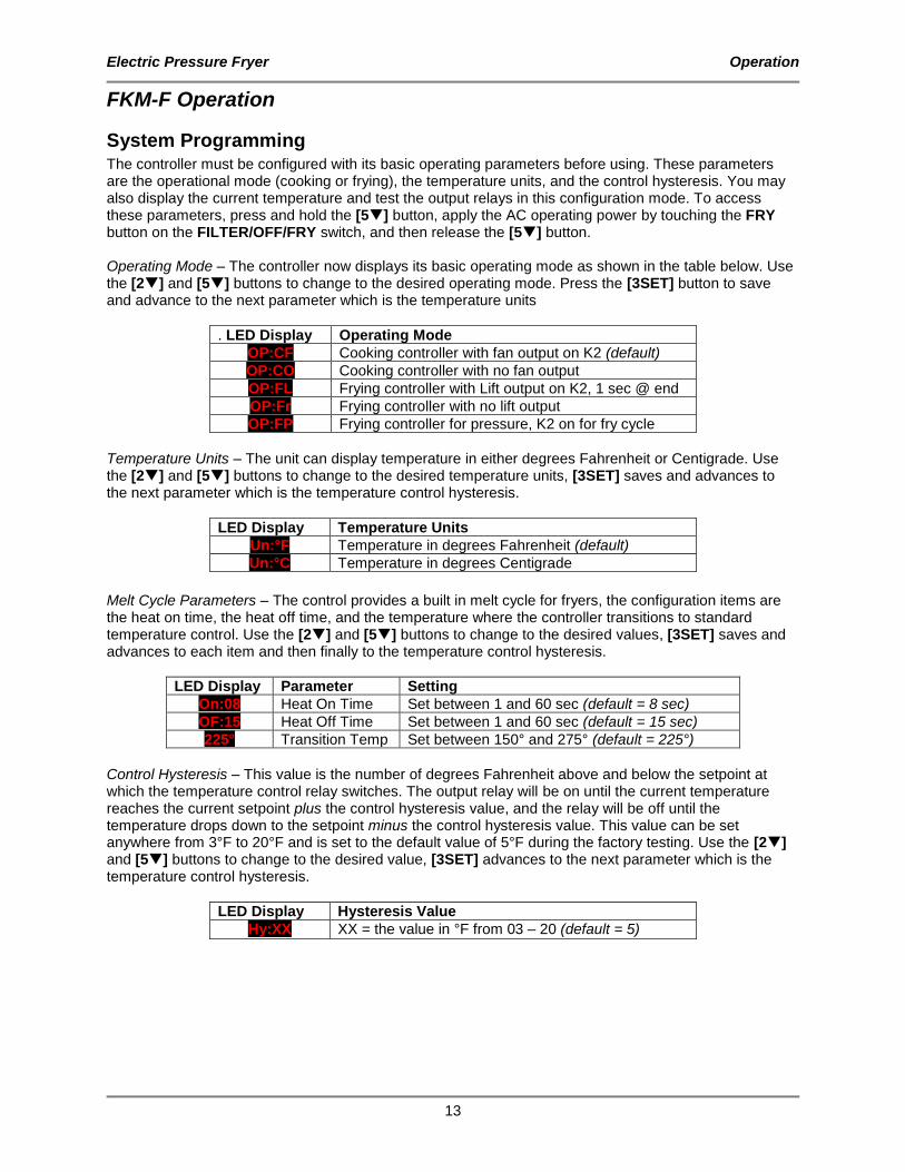
System Programming The controller must be configured with its basic operating parameters before using. These parameters are the operational mode (cooking or frying), the temperature units, and the control hysteresis. You may also display the current temperature and test the output relays in this configuration mode. To access these parameters, press and hold the [5] button, apply the AC operating power by touching the FRY button on the FILTER/OFF/FRY switch, and then release the [5] button. Operating Mode – The controller now displays its basic operating mode as shown in the table below. Use the [2] and [5] buttons to change to the desired operating mode. Press the [3SET] button to save and advance to the next parameter which is the temperature units
. LED Display Operating Mode
OP:CF Cooking controller with fan output on K2 (default)
OP:CO Cooking controller with no fan output
OP:FL Frying controller with Lift output on K2, 1 sec @ end
OP:Fr Frying controller with no lift output
OP:FP Frying controller for pressure, K2 on for fry cycle
Temperature Units – The unit can display temperature in either degrees Fahrenheit or Centigrade. Use the [2] and [5] buttons to change to the desired temperature units, [3SET] saves and advances to the next parameter which is the temperature control hysteresis.
LED Display Temperature Units
Un:°F Temperature in degrees Fahrenheit (default)
Un:°C Temperature in degrees Centigrade
Melt Cycle Parameters – The control provides a built in melt cycle for fryers, the configuration items are the heat on time, the heat off time, and the temperature where the controller transitions to standard temperature control. Use the [2] and [5] buttons to change to the desired values, [3SET] saves and advances to each item and then finally to the temperature control hysteresis.
LED Display Parameter Setting
On:08 Heat On Time Set between 1 and 60 sec (default = 8 sec)
OF:15 Heat Off Time Set between 1 and 60 sec (default = 15 sec)
225° Transition Temp Set between 150° and 275° (default = 225°)
Control Hysteresis – This value is the number of degrees Fahrenheit above and below the setpoint at which the temperature control relay switches. The output relay will be on until the current temperature reaches the current setpoint plus the control hysteresis value, and the relay will be off until the temperature drops down to the setpoint minus the control hysteresis value. This value can be set anywhere from 3°F to 20°F and is set to the default value of 5°F during the factory testing. Use the [2] and [5] buttons to change to the desired value, [3SET] advances to the next parameter which is the temperature control hysteresis.
LED Display Hysteresis Value
Hy:XX XX = the value in °F from 03 – 20 (default = 5)
Electric Pressure Fryer Operation
14
Temperature Display, Temperature Adjustment & Relay Check – Once you press the [3SET] button again the unit displays the current temperature. The following features are available in this mode: Temperature Offset: The control can apply small temperature adjustments to compensate for probe location within the equipment. Press and release the [2] button to add 1°F, press and release it again to add another 1°F. Press and release the [5] button to subtract 1°F, press and release it more to subtract more. The control limits the adjustment to ±10°F. Relay Check: Pressing and releasing the [4] button turns relay K1 (heating relay) on. Press and release the [4] button again to turn it off. Pressing and releasing the [6] button turns relay K2 (Pressure solenoid/lift relay) on. Press and release the [6] button again to turn it off. This mode can be very useful for testing a new piece of equipment by turning the heaters on and watching the temperature rise (and/or current draw) to confirm proper heating operation and then using the fan relay to cool the system down. Press and release the [3SET] button and the configuration wraps around back to the Operating Mode display. Once the configuration is complete turn the controller off and then back on again to begin using the controller in its configured mode.
Electric Pressure Fryer Operation
15
Product Programming The product programs must be set before cooking can begin. To enter editing mode press and hold the [3SET] button for two seconds until the controller emits a double chirp, then the controller first displays the frying temperature. To change the temperature, use the [2] button to increase the highlighted digit value, to decrease that digit press the [5] button. To move the highlight to the other digits, use the [4] and [6] buttons accordingly. Once the temperature is set properly press the [3SET] button to save it and advance to the time cycle editing. Once the [3SET] button is pressed and released the controller displays Edit. To view or edit the time associated with any of the six buttons simply press and release that button and the time is displayed. The time value is adjusted in the same manner as the oil temperature: use the [2] button to increase the highlighted digit value, to decrease that digit press the [5] button. To move the highlight to the other digits, use the [4] and [6] buttons accordingly. Once the time value is set press the [3SET] button and the display returns to displaying Edit. Once the values are all set properly press and hold the [3SET] button for 2 seconds until the controller chirps twice and release the button, the controller is now back to ready mode displaying rdY.

Electric Pressure Fryer Operation
16
Start-Up (FKM-F)
1. Make sure the main drain valve is closed.
Risk of fire exists if the oil level drops below the minimum oil level. The level of oil within the pot must not fall below 5mm of the maximum oil level.
Use of oil/shortening older than the manufacturers recommendations for life of the oil is prone to surge boiling and flash fires. Follow the oil manufacturers guidelines for lifecycle of oil/shortening.
Overfilling the fryer pot with shortening could lead to serious injury. Ensure that the fryer pot is filled with shortening only to the fill mark when shortening is hot. Do not use any shortening other than what is specified in this manual and do not overfill the fryer pot.
The fryer has a maximum temperature setting of 375º F/191º C. Do not use oil/shortening with a flashpoint less than 554º F (290º C)
Use only high-quality shortening that has low moisture content, a high smoke point and no additives.
2. Fill pot with shortening to above the “MIN OIL LEVEL” mark.
Electric Pressure Fryer Operation
17
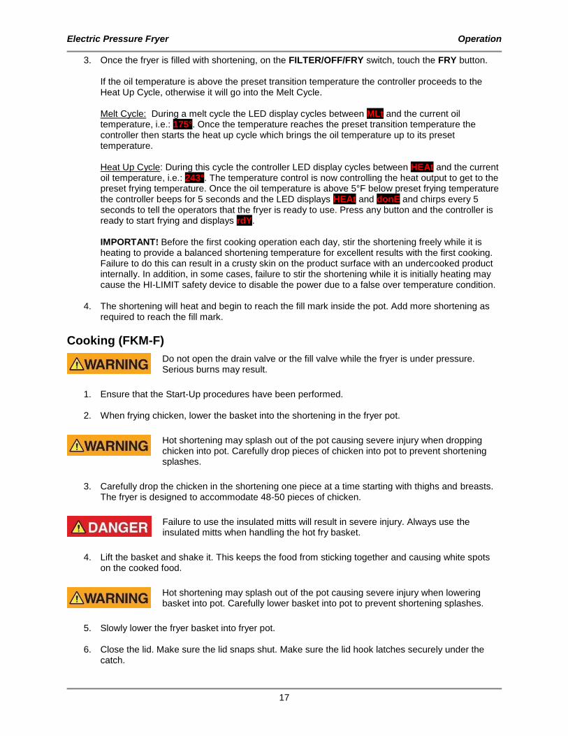
3. Once the fryer is filled with shortening, on the FILTER/OFF/FRY switch, touch the FRY button. If the oil temperature is above the preset transition temperature the controller proceeds to the Heat Up Cycle, otherwise it will go into the Melt Cycle. Melt Cycle: During a melt cycle the LED display cycles between MLt and the current oil temperature, i.e.: 175°. Once the temperature reaches the preset transition temperature the controller then starts the heat up cycle which brings the oil temperature up to its preset temperature. Heat Up Cycle: During this cycle the controller LED display cycles between HEAt and the current oil temperature, i.e.: 243°. The temperature control is now controlling the heat output to get to the preset frying temperature. Once the oil temperature is above 5°F below preset frying temperature the controller beeps for 5 seconds and the LED displays HEAt and donE and chirps every 5 seconds to tell the operators that the fryer is ready to use. Press any button and the controller is ready to start frying and displays rdY. IMPORTANT! Before the first cooking operation each day, stir the shortening freely while it is heating to provide a balanced shortening temperature for excellent results with the first cooking. Failure to do this can result in a crusty skin on the product surface with an undercooked product internally. In addition, in some cases, failure to stir the shortening while it is initially heating may cause the HI-LIMIT safety device to disable the power due to a false over temperature condition.
4. The shortening will heat and begin to reach the fill mark inside the pot. Add more shortening as required to reach the fill mark.
Cooking (FKM-F)
Do not open the drain valve or the fill valve while the fryer is under pressure. Serious burns may result.
1. Ensure that the Start-Up procedures have been performed.
2. When frying chicken, lower the basket into the shortening in the fryer pot.
Hot shortening may splash out of the pot causing severe injury when dropping chicken into pot. Carefully drop pieces of chicken into pot to prevent shortening splashes.
3. Carefully drop the chicken in the shortening one piece at a time starting with thighs and breasts.
The fryer is designed to accommodate 48-50 pieces of chicken.
Failure to use the insulated mitts will result in severe injury. Always use the insulated mitts when handling the hot fry basket.
4. Lift the basket and shake it. This keeps the food from sticking together and causing white spots
on the cooked food.
Hot shortening may splash out of the pot causing severe injury when lowering basket into pot. Carefully lower basket into pot to prevent shortening splashes.
5. Slowly lower the fryer basket into fryer pot.
6. Close the lid. Make sure the lid snaps shut. Make sure the lid hook latches securely under the
catch.

Electric Pressure Fryer Operation
18
7. Tighten the spin handle until the lid is firmly sealed. Then line up the orange knob on the spin handle with the orange knob at the front of the fryer.
8. Activate the timer by pressing the Number Button (1-6) button on the digital timer. The timer will begin the count down. NOTE - To stop the cooking cycle at any time press and hold the [3SET] button for two seconds until you hear a double chirp.
9. When the frying cycle time counts down to 0 the controller displays done and beeps for 5 seconds. At any time the operator can touch any key to return to the ready state.
10. When the pointer on the pressure gauge is at zero, wait 5 seconds then slowly turn the spin handle counterclockwise to break the seal around the lid. The fryer has a locking pin that prevents turning the spin handle until the pressure drops to zero. Do not force the spin handle to open the lid.
11. Slowly open the lid.
Failure to use the insulated mitts will result in injury. Always use the insulated mitts when handling the hot fry basket.
12. Lift the basket and hang it on the front of the fryer pot to drain.
13. Empty the basket.
14. Remember to filter the shortening at least every third frying cycle load. Refer to the procedure in
this manual. Also filter the shortening and clean the fryer at the end of each day. If you do not plan to use the fryer for an hour or more, turn the thermostat down to 150 and close the lid.
15. When you have finished frying for the day, on the FILTER/OFF/FRY switch, touch the OFF button.
Electric Pressure Fryer Operation
19
FKM-FC Operation
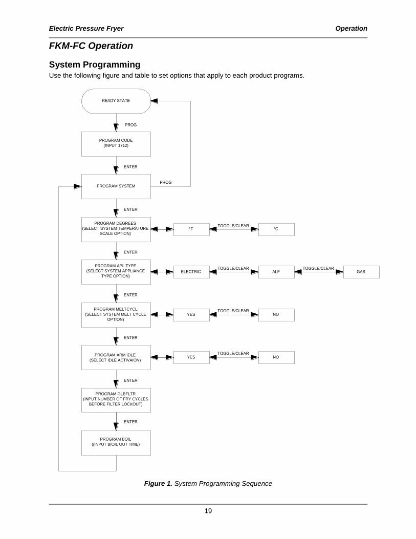
System Programming Use the following figure and table to set options that apply to each product programs.
READY STATE
PROGRAM CODE
(INPUT 1712)
PROGRAM SYSTEM
PROGRAM DEGREES
(SELECT SYSTEM TEMPERATURE
SCALE OPTION)
PROGRAM APL TYPE
(SELECT SYSTEM APPLIANCE
TYPE OPTION)
PROGRAM MELTCYCL
(SELECT SYSTEM MELT CYCLE
OPTION)
PROGRAM GLBFLTR
(INPUT NUMBER OF FRY CYCLES
BEFORE FILTER LOCKOUT)
ELECTRIC
YES
ALF
NO
PROG
PROG
ENTER
ENTER
ENTER
ENTER
ENTER
TOGGLE/CLEAR
TOGGLE/CLEAR
°F °CTOGGLE/CLEAR
ENTER
GASTOGGLE/CLEAR
PROGRAM ARM IDLE
(SELECT IDLE ACTIVAION)
ENTER
PROGRAM BOIL
((INPUT BIOIL OUT TIME)
YES NOTOGGLE/CLEAR
Figure 1. System Programming Sequence
Electric Pressure Fryer Operation
20
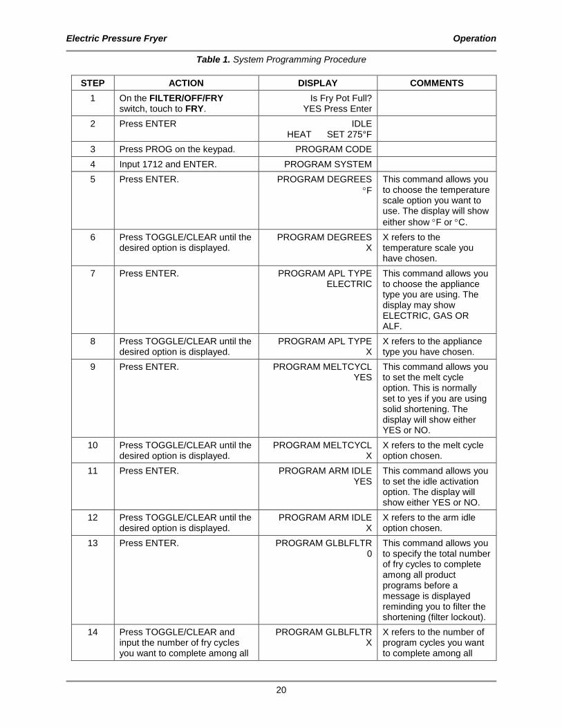
Table 1. System Programming Procedure
STEP ACTION DISPLAY COMMENTS
1 On the FILTER/OFF/FRY switch, touch to FRY.
Is Fry Pot Full? YES Press Enter
2 Press ENTER IDLE HEAT SET 275°F
3 Press PROG on the keypad. PROGRAM CODE
4 Input 1712 and ENTER. PROGRAM SYSTEM
5 Press ENTER. PROGRAM DEGREES
F
This command allows you to choose the temperature scale option you want to use. The display will show
either show F or C.
6 Press TOGGLE/CLEAR until the desired option is displayed.
PROGRAM DEGREES X
X refers to the temperature scale you have chosen.
7 Press ENTER. PROGRAM APL TYPE ELECTRIC
This command allows you to choose the appliance type you are using. The display may show ELECTRIC, GAS OR ALF.
8 Press TOGGLE/CLEAR until the desired option is displayed.
PROGRAM APL TYPE X
X refers to the appliance type you have chosen.
9 Press ENTER. PROGRAM MELTCYCL YES
This command allows you to set the melt cycle option. This is normally set to yes if you are using solid shortening. The display will show either YES or NO.
10 Press TOGGLE/CLEAR until the desired option is displayed.
PROGRAM MELTCYCL X
X refers to the melt cycle option chosen.
11 Press ENTER. PROGRAM ARM IDLE YES
This command allows you to set the idle activation option. The display will show either YES or NO.
12 Press TOGGLE/CLEAR until the desired option is displayed.
PROGRAM ARM IDLE X
X refers to the arm idle option chosen.
13 Press ENTER. PROGRAM GLBLFLTR 0
This command allows you to specify the total number of fry cycles to complete among all product programs before a message is displayed reminding you to filter the shortening (filter lockout).
14 Press TOGGLE/CLEAR and input the number of fry cycles you want to complete among all
PROGRAM GLBLFLTR X
X refers to the number of program cycles you want to complete among all

Electric Pressure Fryer Operation
21
STEP ACTION DISPLAY COMMENTS
product programs before enabling filter lockout.
product programs before filtering the shortening.
15 Press ENTER. PROGRAM BOIL 20:00
This command allows you to specify the boil out time. The time displayed may be a previously programmed value.
16 Press TOGGLE/CLEAR and input the number of minutes you want to clean.
PROGRAM BOIL XX:XX
XX:XX refers to the number of minutes you input.
17 Press ENTER. PROGRAM SYSTEM
18 Press PROG to exit the programming mode.
LOW

Electric Pressure Fryer Operation
22
Product Programming Use the following figure and table to set a maximum of eight product programs. The product programs must be set before cooking can begin.
READY STATE
PROGRAM CODE
(INPUT 1724)
PROGRAM PRODUCT #
(SELECT PROGRAM #, 1-8)
PROGRAM TIMEX
(INPUT STAGE X COOKING TIME)
PROGRAM TEMPX
(INPUT STAGE X COOKING
TEMPERATURE)
PROGRAM TEMPCOMX
(SELECT STAGE X TEMPERATURE
COMPENSATION OPTION
PROGRAM VALVEX
(SELECT STAGE X SOLENOID
VALVE OPTION)
PROGRAM PREALARM
(INPUT PREALARM VALUE)
PROGRAM FILTER
(INPUT NUMBER OF FRY CYCLES
BEFORE FILTER LOCKOUT)
DOES TIME
= 00:00 ?
IS
X <= 5
?
IS
X <= 5
?
FLEX TIME
OPEN
STRAIGHT TIME
CLOSED
PROG
PROG
ENTER
ENTER
ENTER
(ELECTRIC OR GAS) ENTER
ENTER
ENTER
ENTER
(STAGE 1 )
ENTER(STAGE 2, 3, 4, OR 5)
ENTER
YES
NO
YES
NO
YES
NO
(ALF)
ENTERTOGGLE/CLEAR
TOGGLE/CLEAR
Figure 2. Product Programming Sequence

Electric Pressure Fryer Operation
23
Table 2. Product Programming Procedure
STEP ACTION DISPLAY COMMENTS
1 On the FILTER/OFF/FRY switch, touch to FRY.
LOW
2 Press PROG on the keypad. PROGRAM CODE
3 Input 1724 and press ENTER. PROGRAM PRODUCT #
4 Select the program product number (1-8).
PROGRAM PRODUCT X X refers to the program number you selected.
5 Press ENTER. PROGRAM TIME1 00:00
This command allows you to specify the cooking time for this stage. The time displayed may be a previously programmed value.
6 Press TOGGLE/CLEAR and input the number of minutes you want to cook.
PROGRAM TIME1 XX:XX
XX:XX refers to the number of minutes you input.
7 Press ENTER. PROGRAM TEMP1
000 F
This command allows you to specify the cooking temperature for this stage. The temperature displayed may be a previously programmed temperature. The temperature scale may
also display C depending on the system option that is set.
8 Press TOGGLE/CLEAR and input the cooking temperature for product to be cooked.
PROGRAM TEMP1
XXX F
XXX refers to the cooking temperature you input.
9 Press ENTER. PROGRAM TEMPCOM1 FLEX TIME
This command enables you to select whether or not time is allowed for the fryer to recover from temperature loss while cooking during this stage. The FLEX TIME option will allow the fryer to recover from temperature loss.
10 Press TOGGLE/CLEAR until the desired option is displayed.
PROGRAM TEMPCOM1 X
X refers to the temperature compensation option selected.
11 Press ENTER. PROGRAM VALVE1 CLOSED
This command allows you to specify whether the solenoid valve will be open or closed during this stage.

Electric Pressure Fryer Operation
24
STEP ACTION DISPLAY COMMENTS
12 Press TOGGLE/CLEAR until the desired option is displayed.
PROGRAM VALVE1 X
X refers to the solenoid valve option selected. OPEN is used for Models ALF and BLF Automatic Lift fryers. If your program requires the solenoid valve to be closed while cooking, choose the CLOSED option.
13 Repeat steps 5-12 when programming stages 2, 3, 4 and 5 for Electric and Gas appliance types. Repeat steps 5-10 when programming stages 2, 3, 4 and 5 for an ALF appliance type.
The time and temperature of each stage has to be less than the preceding stage.
14 Press ENTER. PROGRAM PREALARM 00:00
This command allows you to specify the number of minutes before the end of the cooking time (for each stage) until the alarm sound The prealarm value displayed may be a previously programmed value.
15 Press TOGGLE/CLEAR and input the prealarm minutes.
PROGRAM PREALARM XX:XX
XX:XX refers to the prealarm minutes you input.
16 Press ENTER. PROGRAM FILTER 0
This command allows you to specify the number of fry cycles you want to complete for this program before a message is displayed reminding you to filter the shortening (filter lockout). The filter value displayed may be a previously programmed value.
17 Press TOGGLE/CLEAR and input the number of fry cycles you want to complete before enabling filter lockout.
PROGRAM FILTER X
X refers to the number of program cycles you want to complete before filtering the shortening.
18 Press ENTER. PROGRAM PRODUCT #
19 If you wish to input more programs, proceed by pressing the next program number and follow steps 5 through 18 or press PROG to exit the programming mode.

Electric Pressure Fryer Operation
25
Start-Up (FKM-FC)
1. Make sure the main drain valve is closed.
Risk of fire exists if the oil level drops below the minimum oil level. The level of oil within the pot must not fall below 5mm of the maximum oil level.
Use of oil/shortening older than the manufacturers recommendations for life of the oil is prone to surge boiling and flash fires. Follow the oil manufacturers guidelines for lifecycle of oil/shortening.
Overfilling the fryer pot with shortening could lead to serious injury. Ensure that the fryer pot is filled with shortening only to the fill mark when shortening is hot. Do not use any shortening other than what is specified in this manual and do not overfill the fryer pot.
The FKM-FC fryer has a maximum temperature setting of 390º F (200º C). Do not use oil/shortening with a flashpoint less than 554º F (290º C)
Use only high-quality shortening that has low moisture content, a high smoke point and no additives.
2. Fill pot with shortening to above the “MIN OIL LEVEL” mark.
Electric Pressure Fryer Operation
26
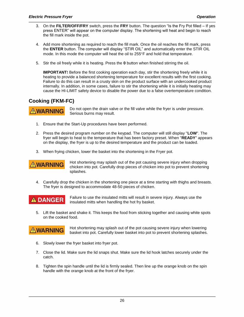
3. On the FILTER/OFF/FRY switch, press the FRY button. The question “Is the Fry Pot filled – If yes press ENTER” will appear on the computer display. The shortening will heat and begin to reach the fill mark inside the pot.
4. Add more shortening as required to reach the fill mark. Once the oil reaches the fill mark, press the ENTER button. The computer will display “STIR OIL” and automatically enter the STIR OIL
mode. In this mode the computer will heat the oil to 255F and hold that temperature.
5. Stir the oil freely while it is heating. Press the 0 button when finished stirring the oil. IMPORTANT! Before the first cooking operation each day, stir the shortening freely while it is heating to provide a balanced shortening temperature for excellent results with the first cooking. Failure to do this can result in a crusty skin on the product surface with an undercooked product internally. In addition, in some cases, failure to stir the shortening while it is initially heating may cause the HI-LIMIT safety device to disable the power due to a false overtemperature condition.
Cooking (FKM-FC)
Do not open the drain valve or the fill valve while the fryer is under pressure. Serious burns may result.
1. Ensure that the Start-Up procedures have been performed.
2. Press the desired program number on the keypad. The computer will still display "LOW". The
fryer will begin to heat to the temperature that has been factory preset. When "READY" appears on the display, the fryer is up to the desired temperature and the product can be loaded.
3. When frying chicken, lower the basket into the shortening in the Fryer pot.
Hot shortening may splash out of the pot causing severe injury when dropping chicken into pot. Carefully drop pieces of chicken into pot to prevent shortening splashes.
4. Carefully drop the chicken in the shortening one piece at a time starting with thighs and breasts.
The fryer is designed to accommodate 48-50 pieces of chicken.
Failure to use the insulated mitts will result in severe injury. Always use the insulated mitts when handling the hot fry basket.
5. Lift the basket and shake it. This keeps the food from sticking together and causing white spots
on the cooked food.
Hot shortening may splash out of the pot causing severe injury when lowering basket into pot. Carefully lower basket into pot to prevent shortening splashes.
6. Slowly lower the fryer basket into fryer pot.
7. Close the lid. Make sure the lid snaps shut. Make sure the lid hook latches securely under the
catch.
8. Tighten the spin handle until the lid is firmly sealed. Then line up the orange knob on the spin handle with the orange knob at the front of the fryer.

Electric Pressure Fryer Operation
27
9. Press the desired program number a second time. The red light above the program number will flash and the computer will display “COOK”. This will start a countdown in minutes and seconds until the end of the cycle.
10. At the end of the cooking cycle, the computer will display "DONE" and signal with a series of audible "beeps". Press the selected number once again to stop the cook cycle. Fifteen seconds before the end of the cook cycle, the program will automatically release the pressure from the fryer. For your safety, the lid will not unlock, even at the end of the cook cycle, until the pressure has been fully released.
Hot steam will escape when you open the lid possibly causing severe injury. Keep your face and arms away from the fry pot.
11. Slowly turn the spin handle counterclockwise to break the seal around the lid. Your fryer has a
locking pin that prevents turning the spin handle until the pressure drops to "0".
12. Slowly open the lid.
Failure to use the insulated mitts will result in injury. Always use the insulated mitts when handling the hot fry basket.
13. Lift the basket and hang it on the front of the fryer pot to drain.
14. Empty the basket.
15. Remember to filter the shortening at least every third frying cycle load. Refer to the procedure in
this manual. Also filter the shortening and clean the fryer at the end of each day.
16. Close the lid and press the 0 button. Idle 275F will display. This will automatically hold the shortening at a cooler temperature.
17. To escape the idle mode, press the 0 button again and the fryer will heat to its original temperature.
18. When you have finished frying for the day, on the FILTER/OFF/FRY switch, touch the OFF button.

Electric Pressure Fryer Maintenance
28
Maintenance
Failure to comply with the maintenance below could result in a serious accident. Do not over-tighten the spindle assembly. (Only tighten to hold pressure.) Your fryer will need periodic maintenance and servicing. We strongly suggest that you use only a service company that is authorized by BKI to do this work. The restraining device must always be connected when the appliance is in service. Disconnect for movement, such as servicing or cleaning. Reconnect the restraint when fryer has been returned to its normal position. The FKM appliance is not intended to be cleaned with a water jet.
Scheduled Maintenance Use the following table to help manage scheduled maintenance activities.
FREQUENCY PERFORMED BY PART ACTIVITY
Each Fry Cycle User Pressure Gauge Check for proper display of cooking vat pressure. Contact authorized BKI service agent if adjustment or replacement is required.
User Lid Gasket Check for unusual wear such as cracks and deformation, and pressure leaks. Contact authorized BKI service agent if adjustment or replacement is required.
Daily User Dead Weight Assembly
Clean weight and orifices daily and check for wear.
User Filter Pad Replace filter pad. Refer to the procedure in this manual.
User Condensation Pan Remove and drain.
User Filter system Filter the shortening using the procedure in this manual.
Weekly User Safety Pop Valve Check for release of pressure and proper seal. Refer to the procedure in this manual.
User Fryer Pot Perform the boil-out procedure in this manual.
Every 6 Months Authorized BKI service agent
Acme Screw and Nut
Check for wear on the threads.
Authorized BKI service agent
Solenoid Valve Check that the valve is holding and releasing pressure when the timer or computer activates it.
Authorized BKI service agent
Hook, Catch, Spring Check for wear and ease of operation.
Authorized BKI service agent
Connections, Fittings
Check for leakage while oil is pumping.

Electric Pressure Fryer Maintenance
29
FREQUENCY PERFORMED BY PART ACTIVITY
Authorized BKI service agent
Fryer Pot Fittings/Connections
Check for leakage around fry pot top deck and fittings (heaters, hi-limit, thermostats, etc.).
Safety Pop Valve Procedure The safety pop valve should be blown under pressure periodically to prevent the seat from sticking.
Failure to use the insulated mitts will result in injury. Always use the insulated mitts when handling the arm on the safety valve.
1. After the pressure is up during a cooking cycle, use the insulated glove to lift the arm on the edge
of the safety valve and let some steam escape. This will clean the valve.
2. Release the lever on the valve, and let it slam shut to seal the valve.

Electric Pressure Fryer Maintenance
30
Troubleshooting
Filter Pump Reset: If the filter pump overheats the lights next to FILTER and OFF buttons will alternate back and forth indicating the pump has tripped. Once the pump has cooled the light next to the FILTER button will flash indicating the pump is ready to be reset. Touch the FILTER button to restart the pump.

Electric Pressure Fryer Replacement Parts
31
Replacement Parts Use the information in this section to identify replacement parts. To order replacement parts, call your local BKI sales and service representative. Before calling, please note the serial number, model number and voltage on the rating tag affixed to the unit.
Assemblies
Description Assembly # Figure # Table #
DEAD WEIGHT ASSEMBLY AN19104100 Figure 3 Table 3
DOOR ASSEMBLY AB19115000 Figure 4 Table 4
DRAIN/MOTOR/PIPING ASSEMBLY N/A Figure 5 Table 5
RELAY ENCLOSURE ASSEMBLY AB16027700 Figure 6 Table 6
FRONT PANEL FKM-F AN19111500 Figure 7
Table 7
FRONT PANEL FKM-FC AB19111700 Figure 8 Table 8
LID/TOP ASSEMBLY SB1992S Figure 9 Table 9
OIL VAT ASSEMBLY AN19313000 Figure 10 Table 10
QUICK DISCONNECT ASSEMBLY
AN19103300 SB1997S
Figure 11 Table 11
REAR PANEL FKM-F AN19114900 Figure 12 Table 12
REAR PANEL FKM-FC AN19114700 Figure 13 Table 13
SOLENOID VALVE AN19104300 Figure 14 Table 14

Electric Pressure Fryer Replacement Parts
32
Figure 3. Dead Weight Assembly
Table 3. Dead Weight Assembly Parts
ITEM # PART # QTY DESCRIPTION
1 FT0395 1 PIPE, POPOFF VALVE BAFF BOX 2 FT0396 1 PIPE, DEAD WT TO BAFFLE BOX 3 O0001 1 ORIFICE, SS 4 O0002 1 GASKET, O-RING #2-222 5 PV0001 1 VALVE, POP SAFETY 1321148 6 FT0066 1 ELL, REDUCER 3/4 X 1/2 90 DEG 7 FT0235 1 NIPPLE, 1/2 X C SS 8 FT0190 1 ELL, STREET 1/4 90 DEG CP 9 FT0084 1 COUPLING, BRASS 1/4 10 FT0563 1 FITTING, COMPRESSION ¾” 11 FT0067 1 BUSHING, C110JO 3/4 X 1/2 CP 12 FT0234 1 NIPPLE, 1/4 X 1 1/2 SS 304 13 C0657 1 COVER, DEAD WEIGHT VALVE FKM 14 B0969 1 BODY, DEAD WEIGHT VALVE FKM 15 W0201 1 WEIGHT, VALVE FKM 12#
16 G0064 1 GAUGE, PRESSURE 30 PSI
Electric Pressure Fryer Replacement Parts
33
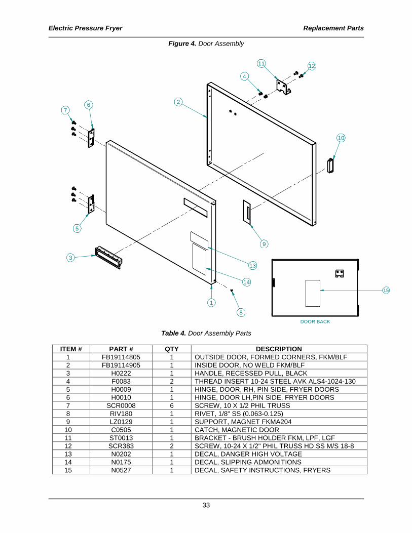
Figure 4. Door Assembly
1
10
4
5
6
3
9
8
7
1211
13
14
2
Table 4. Door Assembly Parts
ITEM # PART # QTY DESCRIPTION
1 FB19114805 1 OUTSIDE DOOR, FORMED CORNERS, FKM/BLF
2 FB19114905 1 INSIDE DOOR, NO WELD FKM/BLF
3 H0222 1 HANDLE, RECESSED PULL, BLACK
4 F0083 2 THREAD INSERT 10-24 STEEL AVK ALS4-1024-130
5 H0009 1 HINGE, DOOR, RH, PIN SIDE, FRYER DOORS
6 H0010 1 HINGE, DOOR LH,PIN SIDE, FRYER DOORS
7 SCR0008 6 SCREW, 10 X 1/2 PHIL TRUSS
8 RIV180 1 RIVET, 1/8" SS (0.063-0.125)
9 LZ0129 1 SUPPORT, MAGNET FKMA204
10 C0505 1 CATCH, MAGNETIC DOOR
11 ST0013 1 BRACKET - BRUSH HOLDER FKM, LPF, LGF
12 SCR383 2 SCREW, 10-24 X 1/2" PHIL TRUSS HD SS M/S 18-8
13 N0202 1 DECAL, DANGER HIGH VOLTAGE
14 N0175 1 DECAL, SLIPPING ADMONITIONS
15 N0527 1 DECAL, SAFETY INSTRUCTIONS, FRYERS
DOOR BACK
15

Electric Pressure Fryer Replacement Parts
34
Figure 5. Drain/Motor/Piping Assembly
16
2
23
24
1722
21
19
28
3026
27
29
35
10
1
3
8
1437
4
34
31
13
12
15
11
33
32
15
2
25
8
9
20
18
6
57
57
13
36
40
38
4
39
39

Electric Pressure Fryer Replacement Parts
35
Table 5. Drain/Motor/Piping Assembly Parts
ITEM # PART # QTY DESCRIPTION
1 AB15507900 1 ASSEMBLY, PUMP DISCONNECT, FILTER VAT, FKG/BLG
2 FT0312 2 ELL, STREET 1/2 90 DEG BLACK
3 FT0619 1 NIPPLE, 1/2" x 1-1/2" LG, SS 304
4 SCR463 8 SCREW, 1/4-20 X 5/8, HEX SER FLNGD
5 FT0153 2 CONNECTOR, BOX 3/8 X 90
6 LPFFA035 1 CONDUIT, 3/8" FLEX 17"
7 F0312 2 BUSHING, CONDUIT 3/8" PLASTIC
8 FT0536 2 COUPLING, 5/8" 45° FLARE TO 1/2" MPT STRAIGHT ELECTROLESS NICKEL
9 TU0206 1 TUBING, 29" 1/2" ID
10 D0060 1 VALVE, DRAIN, SS BALL & PLT. CAR. STEM
11 FT0543 1 DRAIN VALVE BRACKET FRYERS
12 FT0044 1 ELL, STREET 3/8 90 DEG, BLACK
13 FT0412 2 NIPPLE, 3/8" NPT x 1 1/2" SCH 40 BLACK PIPE
14 FT0538 1 TEE, 1/2" x 1/2" x 3/8", BLACK PIPE
15 SB1314 1 BALL VALVE ASSY, FRYERS
16 FT0507 1 CONNECTOR, MALE 10FBU-S, NICKEL PLATED 5/8" TUBE TO 1/2" NPT
17 FKMA224 1 HANDLE SUPPORT PLATE FKM
18 MA19100508 1 FILL VALVE HANDLE
19 H0215 1 DRAIN VALVE HANDEL FKM & BLF
20 C0672 1 COVER, DRAIN HANDLE RED
21 C0668 1 COVER, FILL HANDLE BLACK
22 MA19100800 1 TUBING, TEE TO DISCONNECT FKM
23 P0081 1 PLUG, D-H4F4-SV-8, QUIK DISCONNECT
24 B0851 1 BUSHING, BLACK HEX REDUCING 1/2 x 3/8 NPT 150LB
25 SCR138 3 SCREW, #10 X 1/2" PHIL TRUSS HD
26 LZ0130 1 COVER, MICROSWITCH FKM & BLF
27 F0158 1 BUSHING, BLK 1/2 HEYCO SNAP
28 SCR194 2 SCREW, 6-32 x 1" RND HD, ZINC SLOTTED
29 NUT253 2 NUT, 6-32 S/S 18-8 NYLON
30 S0054 1 SWITCH, MICRO BZ-2RW822-A2
31 F0253 1 PIN, CLEVIS, 3/16 x 1 3/4
32 F0254 2 PIN, COTTER HAIRPIN #213 .080 WIRE DIA
33 F0255 1 PIN, CLEVIS, 3/16 x 1-1/4
34 SP0014 2 SPACER, ALUM .5 X .125
35 SP0034 2 SPACER, DRAIN VALVE BRKT FRYERS
36 WB19315400 1 WELDMENT, FILL HANDLE INDICATIOR
37 M0121 1 MOTOR W/PUMP, 115-208/230/50-60Hz
38 FB19313405 1 BRACKET, PUMP MOTOR MOUNT, FKG/BLG
39 F0140 8 AVK, HEX INSERT, ¼”-20
40 N0695 1 DECAL, DRAIN HANDLE PLATE, FKM

Electric Pressure Fryer Replacement Parts
36
Figure 6. Relay Enclosure Assembly
16
5
13
7
11
9
12
3
13
8
16 15 14
10
2
4
3 4
Table 6. Relay Enclosure Assembly Parts
ITEM # PART # QTY DESCRIPTION
1 FB16022903 1 ENCLOSURE, RELAYS
2 MB55150900 1 DIN RAIL, 35mm x 6.50 in.
3 SCR383 3 SCREW, 10-24 x 1/2" TR HR, SS
4 NUT286 3 NUT, #10-24 KEPS, ZINC PLATED STL
5 FN0058 1 FAN, 230V, 50/60Hz, 60MM, AXIAL
6 R0150 1 RELAY, 4 Pole, 40A, 208-240V, DP
7 TB0125 1 TERMINAL BLOCK, 4 Pole, 2-14 AWG
8 SCR006 4 SCREW, 6 x 1/2" PAN HD, ZINC
9 F0111 1 GROUND TERMINAL, SINGLE HOLE
10 R0195 2 RELAY, SSR, 20-275V, 90A, 1PH
11 F0155 2 BUSHING, 7/8" SNAP (BLACK)
12 F0318 1 CLAMP, 3/8" SAFETY
13 SCR138 3 SCREW, 10 x 1/2" TR HD, ZINC
14 TB0109 2 TERMINAL BLOCK END STOP
15 TB0004 1 TERMINAL END PLATE, 3 x 8 AWG
16 TB0003 3 TERMINAL BLOCK, 3 x 8 AWG
17* WH0153 1 WIRING HARNESS, RELAYS, ELECTRIC FRYERS
* Not Shown

Electric Pressure Fryer Replacement Parts
37
Figure 7. Front Panel FKM-F
4
6
2
1
3
5
7
Table 7. Front Panel FKM-F Parts
ITEM # PART # QTY DESCRIPTION
1 FB19111405 1 CONTROL PANEL FKM-F, CAPACITIVE TOUCH
2 N0684 1 DECAL, CONTROL PANEL, FKM-F, CAPACITIVE TOUCH
3 CP0066 1 CONTROL, TIME & TEMPERATURE 6 RECIPE, 200-250V 50/60 Hz
4 SP0052 4 SPACER, 5/16 OD, 1/4 L, #10 ID ALUMINUM
5 S0707 1 SWITCH, CAPACITIVE TOUCH, 3-BUTTON
6 WSH089 4 WASHER, #6 INT LOCK ZINC PLATED
7 NUT048 4 NUT, 6-32 HEX ZINC PLTD

Electric Pressure Fryer Replacement Parts
38
Figure 8. Front Panel FKM-FC
1
7 8
9
2
10
11
11
3
4
Table 8. Front Panel FKM-FC
ITEM # PART # QTY DESCRIPTION
1 FB19111605 1 CONTROL PANEL, FKM-FC, CAPACITIVE TOUCH
2 N0688 1 DECAL, CONTROL PANEL, FKM-FC, CAP. TOUCH
3 SP0052 4 SPACER, #10 ID x 1/4" 5/16" OD, ALUMINUM
4 S0707 1 SWITCH, CAPACITIVE TOUCH 3 BUTTON FRYER
5 CP0039 1 CONTROLLER, VFD LESS HARNESS
6 NUT286 6 NUT, #10-24 KEPS, ZINC PLATED STL
7 SP0030 1 SPACER, POLYESTER (CP0039 DECALS)
8 R0174 2 RELAY, CONTROL, SPDT, 24V COIL CONTACT
9 NUT253 8 NUT, #6-32, NYLON LOCK, SSTL
10 EA16097000* 1 WIRING HARNESS, CP0039 ADAPTER, FRYERS
* Not Shown

Electric Pressure Fryer Replacement Parts
39
Figure 9. Lid/Top (sheet 1 of 4)

Electric Pressure Fryer Replacement Parts
40
Figure 9. Lid/Top (Sheet 2 of 4)

Electric Pressure Fryer Replacement Parts
41
Figure 9. Lid/Top (Sheet 3 of 4)
Electric Pressure Fryer Replacement Parts
42
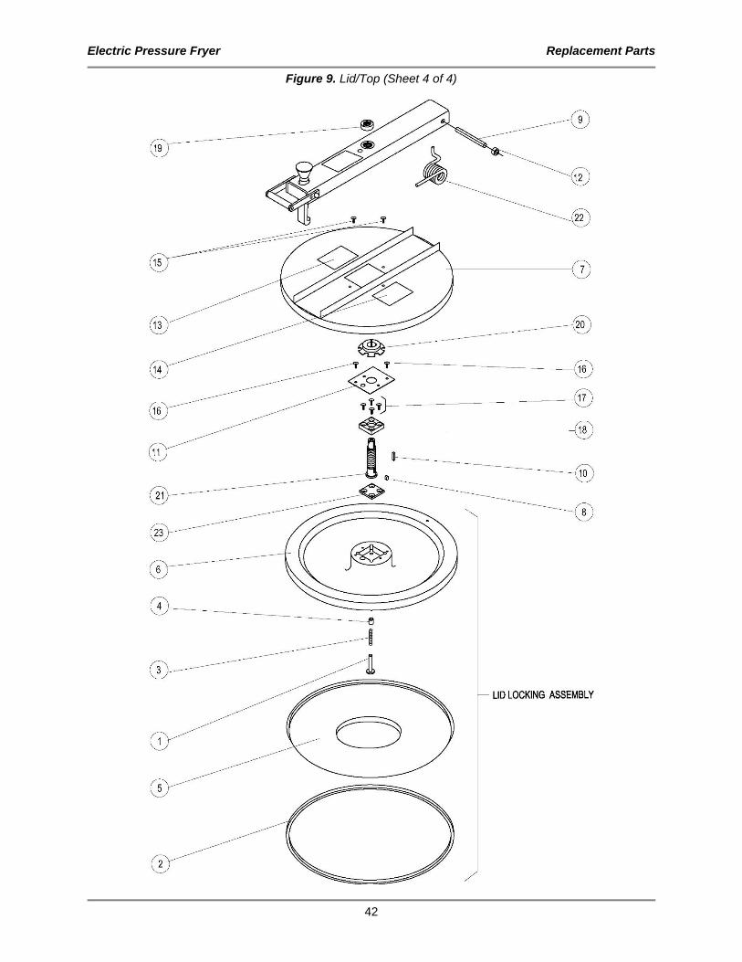
Figure 9. Lid/Top (Sheet 4 of 4)

Electric Pressure Fryer Replacement Parts
43
Table 9. Lid/Top Parts
ITEM # PART # QTY DESCRIPTION
Figure 9 (sheet 1) SB1992S LID/TOP
Figure 9 (sheet 2) SB3481 1 HANDLE ASSY, SPIN 1 FT0332 3 STUD, 5.5” TIGHTEN DN HN
2 K0003 2 KNOB, BLACK #85C
3 K0020 1 HUB, TIGHTEN DOWN
4 K0043 1 KNOB, ORANGE
Figure 9 (sheet 3) AB19103900 1 ARM ASSY, FKM 1 A0120 1 ARM COMPLETE FKM LGF 2 H0155 1 HANDLE, BLK DELRIN FKM LPF LGF 3 P0094 1 PIN, HOOK FKM, LPF, LGF 4 H0024 1 HOOK, LID 1018 ALLOY 5 K0043 1 KNOB, ORANGE 6 N0160 1 DECAL, WARNING BEFORE USING 7 NUT128 2 NUT, 5/16-18 SS 18-8 CAP 8 S0091 1 SPRING, HOOK LGF LPF FKM 9 SCR122 2 SCREW, 1/4-20 X 1/2 FLAT HD 10 SCR259 2 SCREW, 1/4-20 X 1/2 PHIL RD HD 11 TB0020 1 BUSHING, BRONZE 1" 12 H0156 2 HANDLE SIDE FOR H0155 FKM LPF LGF 13 WSH045 2 WASHER, 5/16 LOCK ZINC PLTD 14 WSH102 2 WASHER, 1/4 INT LOCK 15 FT0407 1 PLUG, HOLE 3/8" SHORT PRONG 16 F0026 1 ROLL PIN, 5/32 X 3/4
Figure 9 (sheet 4) SB1989 1 LID LOCKING ASSY W/INSERT FKM 1 F0353 1 PIN, LOCKING FKM LGF LPF 2 G0016 1 GASKET, FKM LID BONDED SILICON 3 S0155 1 SPRING, LOCKING PIN W/LID INSERT 4 B0857 1 BUSHING, BRONZE 3/8X9/16X5/8 5 P0115 1 LID INSERT, FKM 6 FK0010 1 LID, FKM CAST ALUM 7 C0674 * 1 LID COVER AND ARM GUIDE FKM 8 F0107 1 LOCK KEY PIN, FRYERS 9 FKMA016 1 PIN, HINGE 10 FKMA152 1 KEY, TIGHTEN DOWN SCREW 11 FKMA201 1 PLATE, TIGHTEN DOWN FKM 12 FT0049 2 COLLAR, 1/2" SET BRIGHT 13 N0153 * 1 DECAL, FKM WARNING ACME SCREW 14 N0345 * 1 DECAL, HOOK LID INSTRUCTIONS 15 SCR383 2 SCREW, 10-24 X 1/2" PHIL TRUSS HD
16 SCR176 2 SCREW, 8-32 X 3/8 SLOT BINDING
17 SCR178 1 SCREW, 5/16-18 X 1 FLAT HD 18 TB0021 1 TIGHTEN DOWN BASE COLD ROLLED 19 TC0003 1 COLLAR, THREADED SHAFT 20 TC0005 1 COLLAR, LOCKING RING 21 TS0010 1 SCREW, TIGHTEN DOWN 22 S0071 1 SPRING, TORSION
23 LZ0107 1 PLATE, LID FOR LOCKING DEVICE
* - These parts constitute Lid Cover Assembly, AN1910840S.

Electric Pressure Fryer Replacement Parts
44
Figure 10. Oil Vat Assembly
2
7
5
3
4
8
6
10
9
1
11
13
12
12

Electric Pressure Fryer Replacement Parts
45
Table 10. Oil Vat Assembly Parts
ITEM # PART # QTY DESCRIPTION
AN19313000 1 FILTER SCREEN ASSY,FKG
1 WB16010600 1 WELDMENT, FILTER VAT QUICK DISCONNECT 2 WB16022100 1 WELDMENT, FILTER TUBE, BLF
3 FS0002 1 FILTER SCREEN, INTERCEPTOR 4 FS0003 1 FILTER SCREEN, TOP 5 FS0001 1 FILTER SCREEN, BOTTOM 6 SB7659 1 FILTER SCREEN FITTING SPOTWELD 7 FC0004 1 NUT SCREEN RETAINING FKM-F & FKM-FC 8 O0013 1 O-RING, FLUOROCARBON V680-70 9 SCR344 1 SCREW, SET, SOC, 8-32 X 1/4
10 SB7675 1 CRUMB BASKET WELD, LG VAT ASSY 11 FB19312904 1 COVER, FILTER VAT, SHEET METAL FRAME 12 N0395 1 DECAL, VAT COVER SAFETY WARN 13 N0694 2 DECAL, CAUTION, SHARP EDGES
Figure 11. Quick Disconnect Assembly
Table 11. Quick Disconnect Assembly Parts
ITEM # PART # QTY DESCRIPTION
1 B0996 1 BALL, 11/16" STEEL BEARING 2 FT0429 1 QUICK DISCONNECT, PUMP SIDE 3 FT0500 1 QUICK DISCONNECT, VAT SIDE 4 FT0536* 1 COUPLING, 5/8 45¦ FLARE TO 5 O0013 2 O-RING, FLUOROCARBON V680-70 6 O0014 1 O-RING, PARKER #2-124 LARGE 7 S0138 1 SPRING, FOR QUICK DISCONNECT 8 SCR4531* 2 SCREW, #10 24X3/8" WASHERED
* - Not included with SB1997S
Electric Pressure Fryer Replacement Parts
46
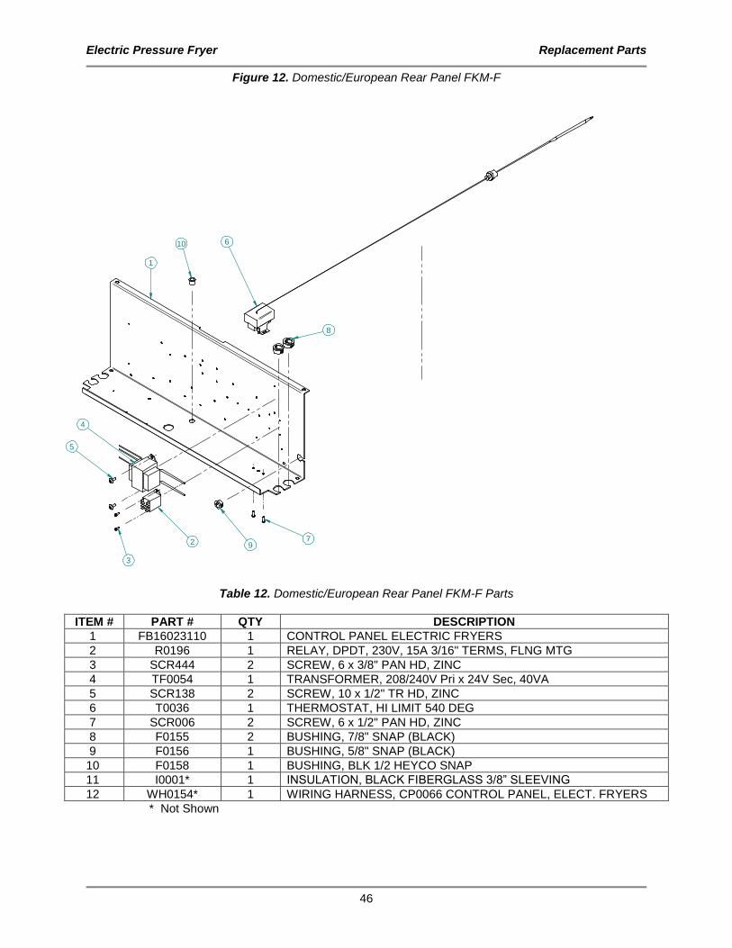
Figure 12. Domestic/European Rear Panel FKM-F
1
2
3
4
5
6
7
10
8
9
Table 12. Domestic/European Rear Panel FKM-F Parts
ITEM # PART # QTY DESCRIPTION
1 FB16023110 1 CONTROL PANEL ELECTRIC FRYERS
2 R0196 1 RELAY, DPDT, 230V, 15A 3/16" TERMS, FLNG MTG
3 SCR444 2 SCREW, 6 x 3/8" PAN HD, ZINC
4 TF0054 1 TRANSFORMER, 208/240V Pri x 24V Sec, 40VA
5 SCR138 2 SCREW, 10 x 1/2" TR HD, ZINC
6 T0036 1 THERMOSTAT, HI LIMIT 540 DEG
7 SCR006 2 SCREW, 6 x 1/2" PAN HD, ZINC
8 F0155 2 BUSHING, 7/8" SNAP (BLACK)
9 F0156 1 BUSHING, 5/8" SNAP (BLACK)
10 F0158 1 BUSHING, BLK 1/2 HEYCO SNAP
11 I0001* 1 INSULATION, BLACK FIBERGLASS 3/8” SLEEVING
12 WH0154* 1 WIRING HARNESS, CP0066 CONTROL PANEL, ELECT. FRYERS
* Not Shown
Electric Pressure Fryer Replacement Parts
47
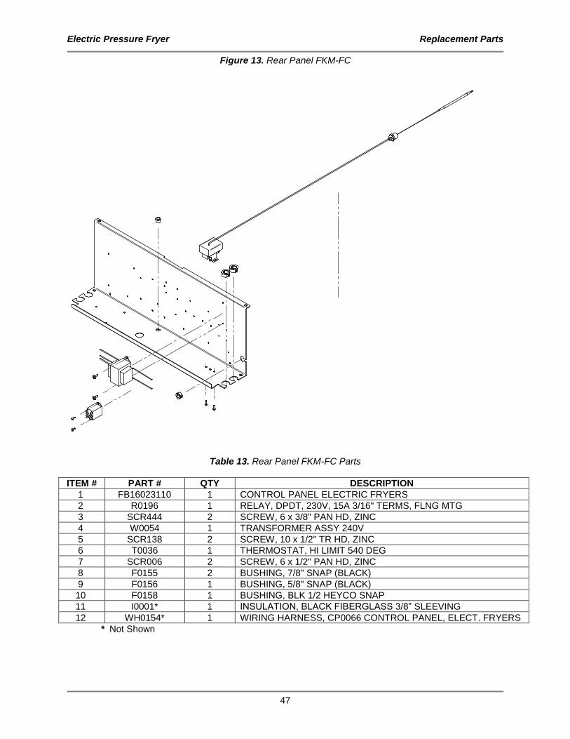
Figure 13. Rear Panel FKM-FC
Table 13. Rear Panel FKM-FC Parts
ITEM # PART # QTY DESCRIPTION
1 FB16023110 1 CONTROL PANEL ELECTRIC FRYERS
2 R0196 1 RELAY, DPDT, 230V, 15A 3/16" TERMS, FLNG MTG
3 SCR444 2 SCREW, 6 x 3/8" PAN HD, ZINC
4 W0054 1 TRANSFORMER ASSY 240V
5 SCR138 2 SCREW, 10 x 1/2" TR HD, ZINC
6 T0036 1 THERMOSTAT, HI LIMIT 540 DEG
7 SCR006 2 SCREW, 6 x 1/2" PAN HD, ZINC
8 F0155 2 BUSHING, 7/8" SNAP (BLACK)
9 F0156 1 BUSHING, 5/8" SNAP (BLACK)
10 F0158 1 BUSHING, BLK 1/2 HEYCO SNAP
11 I0001* 1 INSULATION, BLACK FIBERGLASS 3/8” SLEEVING
12 WH0154* 1 WIRING HARNESS, CP0066 CONTROL PANEL, ELECT. FRYERS
* Not Shown
Electric Pressure Fryer Replacement Parts
48
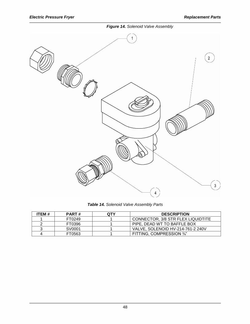
Figure 14. Solenoid Valve Assembly
Table 14. Solenoid Valve Assembly Parts
ITEM # PART # QTY DESCRIPTION
1 FT0249 1 CONNECTOR, 3/8 STR FLEX LIQUIDTITE 2 FT0396 1 PIPE, DEAD WT TO BAFFLE BOX 3 SV0001 1 VALVE, SOLENOID HV-214-761-2 240V 4 FT0563 1 FITTING, COMPRESSION ¾”

Electric Pressure Fryer Replacement Parts
49
Components
Description Component # Figure # Item #
ARM ADJUSTABLE STOP /FKM A0101 Figure 15 1
CASTER, SWIVEL, W/TOP PLATE 5" W/BRAKE C0406 Figure 15 2
BAFFLE BOX ASSEMBLY AN19302600 Figure 15 3
CONDENSATION PAN WELDMENT WB19311100 Figure 15 4
DRAIN PIPE, CONDENSATE FKM MB19310600 Figure 15 5
FILTER BAG CLIP FKM-F ST0015 Figure 15 6
COLLAR, 1/2" SET BRIGHT FT0049 Figure 15 7
SLIDE, UHMW U-SHAPE .5 X 1/8ID S0106 Figure 15 8
SIDE CABINET, L&R FKM/DNF FKMA399 Figure 15 9
HINGE, SLIP WING RH H0051 Figure 15 10
HINGE, SLIP WING LH H0052 Figure 15 11
CALROD, 208V 5675W CALROD, 240V 5675W CALROD, 480V 5675W
C0030 C0031 C0132
Figure 15 12
WASHER, PTFE-FRYER CALROD FT0059 Figure 15 13
BRACKET, CALROD FKMA258 LZ0006 Figure 15 14
BRACKET BACK PLATE FKMA259 LZ0007 Figure 15 15
TEMP. PROBE, 100 Ohm RTD, w/ FTGS T0187 Figure 15 16
THERMISTER PROBE/FTGS ASSEMBLY SB7656 Figure 15 17
CLAMP, HOSE, #62M10 HF0013 Figure 15 18
Figure 15. Components
1 2 3
4 5 6

Electric Pressure Fryer Replacement Parts
50
7 8 9
10 11 12
13 14 15
16 17 18
Electric Pressure Fryer Replacement Parts
51
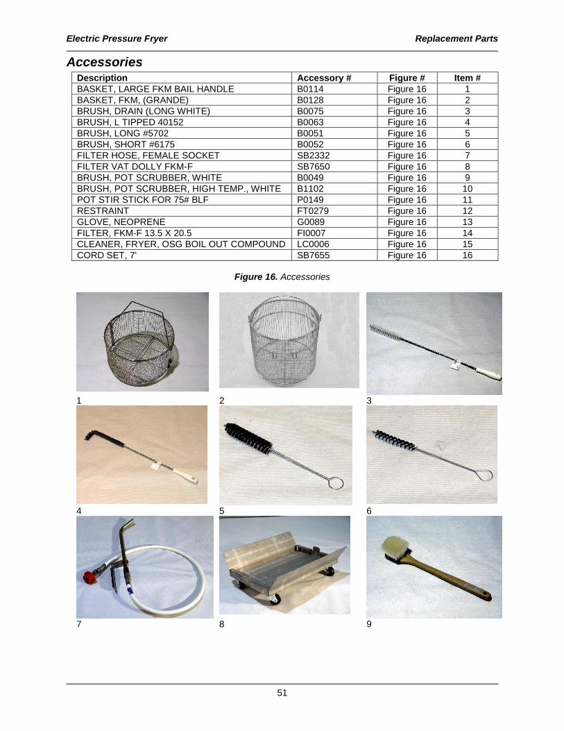
Accessories Description Accessory # Figure # Item #
BASKET, LARGE FKM BAIL HANDLE B0114 Figure 16 1
BASKET, FKM, (GRANDE) B0128 Figure 16 2
BRUSH, DRAIN (LONG WHITE) B0075 Figure 16 3
BRUSH, L TIPPED 40152 B0063 Figure 16 4
BRUSH, LONG #5702 B0051 Figure 16 5
BRUSH, SHORT #6175 B0052 Figure 16 6
FILTER HOSE, FEMALE SOCKET SB2332 Figure 16 7
FILTER VAT DOLLY FKM-F SB7650 Figure 16 8
BRUSH, POT SCRUBBER, WHITE B0049 Figure 16 9
BRUSH, POT SCRUBBER, HIGH TEMP., WHITE B1102 Figure 16 10
POT STIR STICK FOR 75# BLF P0149 Figure 16 11
RESTRAINT FT0279 Figure 16 12
GLOVE, NEOPRENE G0089 Figure 16 13
FILTER, FKM-F 13.5 X 20.5 FI0007 Figure 16 14
CLEANER, FRYER, OSG BOIL OUT COMPOUND LC0006 Figure 16 15
CORD SET, 7' SB7655 Figure 16 16
Figure 16. Accessories
1 2 3
4 5 6
7 8 9

Electric Pressure Fryer Replacement Parts
52
10 11 12
13 14 15

Electric Pressure Fryer Wiring Diagrams
53
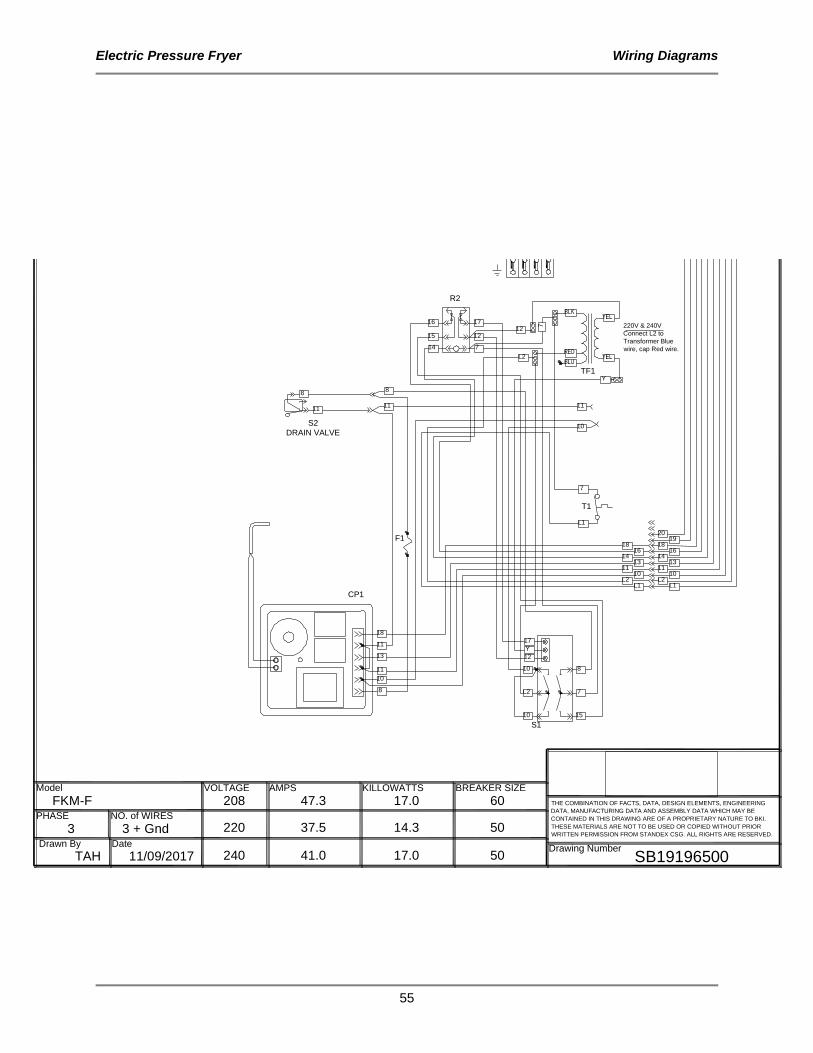
Wiring Diagrams
10
10
17
12
8F1
15
18
1018V1
COMPONENT LEGEND
F1- FU010UK FUSE, 500 mA
CP1- CP0066 CONTROL, TIME & TEMPFN1- FN0058 COOLING FAN, 230V
H1\C0030 CALROD, 5675W@208V H2-C0031 CALROD, 5675W@230V H3/
M1-M0121 MOTOR/PUMP, 208-230V
R1-R0150 CONTACTOR, 50A 4P
R2-R196 RELAY, DPDT 220/240V S1-S0712 SWITCH, TOUCH ON/OFF
S2-S0054 SWITCH, ROLLER ARM
SSR1-R0195 RELAY, SSR, 90A, 20-275VACSSR2 /
T1- T0036 THERMOSTAT, HIGH LIMIT
TB1-TB0125 #4, 4 P TERMINAL BLOCKTB2-TB0003 #8, 3 POLE SECTION
TB0004 #8, 3 POLE END SECTION TB0109 TERMINAL END STOPTF1 - TF0054 TRANSFORMER, 24 Vac
V1- SV0001 VALVE, SOLENOID, 240V
11
CP1
R111 10
SSR1
SSR210
13
13
13
10
H1
4
6
24 Vac
108
7B
LK
RE
D
YE
L
YE
LB
LU
TF1
M1
108
8
11
10
10
10
18
20
19
FN1
H1
H2
H3
R1
L1 L3L2
63
2
1 4
L1
LADDER DIAGRAM
S1
T1
G
L2
S211
10
2
7
4
42
2
6
6
44
22
66
10
13
1 2 3
31L1
L2
L3
L1
L2
SS
R1
SS
R2
R1
TB1
TB2
A1 A2
L1
T1
A1 A2
L1
T1
VOLTAGE
PHASE
AMPS
NO. of WIRES
BREAKER SIZE
THE COMBINATION OF FACTS, DATA, DESIGN ELEMENTS, ENGINEERING
DATA, MANUFACTURING DATA AND ASSEMBLY DATA WHICH MAY BE
CONTAINED IN THIS DRAWING ARE OF A PROPRIETARY NATURE TO BKI.
THESE MATERIALS ARE NOT TO BE USED OR COPIED WITHOUT PRIOR
WRITTEN PERMISSION FROM STANDEX CSG. ALL RIGHTS ARE RESERVED.
Model
Drawing Number
REV ECO DESCRIPTION DATE
208
240
220
47.3
41.0
37.5
KILLOWATTS
17.0
17.0
14.3
60
50
503 + Gnd3
FKM-F
Drawn By Date
TAH 11/09/2017 SB19196500
R27
R215
L2
16
14
16P1
14PS
L2
P2
7
T1
TF1
S2
DRAIN VALVE
8
10
11
13
11
18
7
L1
10
11
88
1111
14
12
17
L2
7
2019
18 1816 16
14 141313
11 111010
L2 L2L1L1
R2
220V & 240V
Connect L2 to
Transformer Blue
wire, cap Red wire.
CP1
F1
15
16
7
12
Y
S1
8
7
15
Y
17
12
10
L2
10
M1
P1
PS
TS
T1
T2
T3
T4
T5
T8
L2
16
14
V1
1614
01 18-090 PRODUCTION RELEASE 07/20/18
R217 12
L2

Electric Pressure Fryer Wiring Diagrams
54
10
10
17
12
8F1
15
18
1018V1
COMPONENT LEGEND
F1- FU010UK FUSE, 500 mA
CP1- CP0066 CONTROL, TIME & TEMP
FN1- FN0058 COOLING FAN, 230V
H1\C0030 CALROD, 5675W@208V H2-C0031 CALROD, 5675W@230V
H3/
M1-M0121 MOTOR/PUMP, 208-230V
R1-R0150 CONTACTOR, 50A 4P
R2-R196 RELAY, DPDT 220/240V S1-S0712 SWITCH, TOUCH ON/OFF
S2-S0054 SWITCH, ROLLER ARM
SSR1-R0195 RELAY, SSR, 90A, 20-275VACSSR2 /
T1- T0036 THERMOSTAT, HIGH LIMIT
TB1-TB0125 #4, 4 P TERMINAL BLOCK
TB2-TB0003 #8, 3 POLE SECTION
TB0004 #8, 3 POLE END SECTION TB0109 TERMINAL END STOP
TF1 - TF0054 TRANSFORMER, 24 Vac
V1- SV0001 VALVE, SOLENOID, 240V
11
CP1
R111 10
SSR1
SSR210
13
13
13
10
H1
4
6
24 Vac
108
7
BL
K
RE
D
YE
L
YE
LB
LU
TF1
M1
108
8
11
10
10
10
18
20
19
FN1
H1
H2
H3
R1
L1 L3L2
63
2
1 4
L1
LADDER DIAGRAM
S1
T1
G
L2
S211
10
2
7
4
42
2
6
6
44
22
66
10
13
1 2 3
31L1
L2
L3
L1
L2
SS
R1
SS
R2
R1
TB1
TB2
A1 A2
L1
T1
A1 A2
L1
T1
VOLTAGE
PHASE
AMPS
NO. of WIRES
BREAKER SIZE
THE COMBINATION OF FACTS, DATA, DESIGN ELEMENTS, ENGINEERING
DATA, MANUFACTURING DATA AND ASSEMBLY DATA WHICH MAY BE
CONTAINED IN THIS DRAWING ARE OF A PROPRIETARY NATURE TO BKI.
THESE MATERIALS ARE NOT TO BE USED OR COPIED WITHOUT PRIOR
WRITTEN PERMISSION FROM STANDEX CSG. ALL RIGHTS ARE RESERVED.
Model
Drawing Number
REV ECO DESCRIPTION DATE
208
240
220
47.3
41.0
37.5
KILLOWATTS
17.0
17.0
14.3
60
50
503 + Gnd3
FKM-F
Drawn By Date
TAH 11/09/2017 SB19196500
R27
R215
L2
16
14
16P1
14PS
L2
P2
7
T1
TF1
S2
DRAIN VALVE
8
10
11
13
11
18
7
L1
10
11
88
1111
14
12
17
L2
7
2019
18 1816 16
14 141313
11 111010
L2 L2L1L1
R2
220V & 240V
Connect L2 to
Transformer Blue
wire, cap Red wire.
CP1
F1
15
16
7
12
Y
S1
8
7
15
Y
17
12
10
L2
10
M1
P1
PS
TS
T1
T2
T3
T4
T5
T8
L2
16
14
V1
1614
01 18-090 PRODUCTION RELEASE 07/20/18
R217 12
L2
Electric Pressure Fryer Wiring Diagrams
55
10
10
17
12
8F1
15
18
1018V1
COMPONENT LEGEND
F1- FU010UK FUSE, 500 mA
CP1- CP0066 CONTROL, TIME & TEMPFN1- FN0058 COOLING FAN, 230V
H1\C0030 CALROD, 5675W@208V H2-C0031 CALROD, 5675W@230V H3/
M1-M0121 MOTOR/PUMP, 208-230V
R1-R0150 CONTACTOR, 50A 4P
R2-R196 RELAY, DPDT 220/240V S1-S0712 SWITCH, TOUCH ON/OFF
S2-S0054 SWITCH, ROLLER ARM
SSR1-R0195 RELAY, SSR, 90A, 20-275VACSSR2 /
T1- T0036 THERMOSTAT, HIGH LIMIT
TB1-TB0125 #4, 4 P TERMINAL BLOCKTB2-TB0003 #8, 3 POLE SECTION
TB0004 #8, 3 POLE END SECTION TB0109 TERMINAL END STOPTF1 - TF0054 TRANSFORMER, 24 Vac
V1- SV0001 VALVE, SOLENOID, 240V
11
CP1
R111 10
SSR1
SSR210
13
13
13
10
H1
4
6
24 Vac
108
7
BL
K
RE
D
YE
L
YE
LB
LU
TF1
M1
108
8
11
10
10
10
18
20
19
FN1
H1
H2
H3
R1
L1 L3L2
63
2
1 4
L1
LADDER DIAGRAM
S1
T1
G
L2
S211
10
2
7
4
42
2
6
6
44
22
66
10
13
1 2 3
31L1
L2
L3
L1
L2
SS
R1
SS
R2
R1
TB1
TB2
A1 A2
L1
T1
A1 A2
L1
T1
VOLTAGE
PHASE
AMPS
NO. of WIRES
BREAKER SIZE
THE COMBINATION OF FACTS, DATA, DESIGN ELEMENTS, ENGINEERING
DATA, MANUFACTURING DATA AND ASSEMBLY DATA WHICH MAY BE
CONTAINED IN THIS DRAWING ARE OF A PROPRIETARY NATURE TO BKI.
THESE MATERIALS ARE NOT TO BE USED OR COPIED WITHOUT PRIOR
WRITTEN PERMISSION FROM STANDEX CSG. ALL RIGHTS ARE RESERVED.
Model
Drawing Number
REV ECO DESCRIPTION DATE
208
240
220
47.3
41.0
37.5
KILLOWATTS
17.0
17.0
14.3
60
50
503 + Gnd3
FKM-F
Drawn By Date
TAH 11/09/2017 SB19196500
R27
R215
L2
16
14
16P1
14PS
L2
P2
7
T1
TF1
S2
DRAIN VALVE
8
10
11
13
11
18
7
L1
10
11
88
1111
14
12
17
L2
720
1918 18
16 1614 14
131311 11
1010L2 L2
L1L1
R2
220V & 240V
Connect L2 to
Transformer Blue
wire, cap Red wire.
CP1
F1
15
16
7
12
Y
S1
8
7
15
Y
17
12
10
L2
10
M1
P1
PS
TS
T1
T2
T3
T4
T5
T8
L2
16
14
V1
1614
01 18-090 PRODUCTION RELEASE 07/20/18
R217 12
L2

Electric Pressure Fryer Wiring Diagrams
56
COMPONENT LEGEND
CP1- CP0039 CONTROL, COMPUTER
FN1- FN0058 COOLING FAN, 230VH1\C0030 CALROD, 5675W@208V
H2-C0031 CALROD, 5675W@230V
H3/M1-M0121 MOTOR/PUMP, 208-230V
R1-R0150 CONTACTOR, 50A 4P
R2-R196 RELAY, DPDT 220/240VR3- R0174 RELAY, SPDT, 20A, 24VDC
R4/
S1-S0712 SWITCH, TOUCH ON/OFFS2-S0054 SWITCH, ROLLER ARM
SSR1-R0195 RELAY, SSR, 90A, 20-275VAC
SSR2 /T1- T0036 THERMOSTAT, HIGH LIMIT
TB1-TB0125 #4, 4 P TERMINAL BLOCK
TB2-TB0003 #8, 3 POLE SECTION
TB0004 #8, 3 POLE END SECTION TB0109 TERMINAL END STOP
TF1 - TF0054 TRANSFORMER, 24 Vac
V1- SV0001 VALVE, SOLENOID, 240V
R215 16
R217 12
R27 14
L2
7
COMPUTER
Wh
ite
Wh
ite
Violet
Red
Gray
Pro
be
18
Red
Re
d
Orange
11
13
Re
d
Violet
11
T1
S2
DRAIN VALVE
8
10
11
13
11
18
7
L1
10
11
88
1111
2019
18 1816 16
14 141313
11 111010
L2 L2L1L1
F1
18
11
13
11
Gre
en
TF1
14
12
17
7
R2
220V & 240V
Connect L2 to
Transformer Blue
wire, cap Red wire.
15
16
7
12
Y
S1
8
7
15
12
Y
Y
17
12
10
L2
10
White
White
01 18-090 PRODUCTION RELEASE 07/20/18
L2
A1 A2
L1
T1
A1 A2
L1
T1
SS
R1
SS
R2
R1
TB1
TB2
4
42
2
6
6
44
22
66
10
13
1 2 3
31L1
L2
L3
L1
L2
11
10
10
10
18
20
19
FN1
H1
H2
H3
R1
L1 L3L2
63
2
1 4
L1
LADDER DIAGRAM
S1
T1
G
L2
S211
10
2
7
24 Vac
108
7
BL
K
RE
D
YE
L
YE
LB
LU
TF1
M1
10
8
11
CP1
R111 10
SSR1
SSR210
13
13
10
H1
4
6
1018 V1
15 10
10
17
12
F1
VOLTAGE
PHASE
AMPS
NO. of WIRES
BREAKER SIZE
THE COMBINATION OF FACTS, DATA, DESIGN ELEMENTS, ENGINEERING
DATA, MANUFACTURING DATA AND ASSEMBLY DATA WHICH MAY BE
CONTAINED IN THIS DRAWING ARE OF A PROPRIETARY NATURE TO BKI.
THESE MATERIALS ARE NOT TO BE USED OR COPIED WITHOUT PRIOR
WRITTEN PERMISSION FROM STANDEX CSG. ALL RIGHTS ARE RESERVED.
Model
Drawing Number
REV ECO DESCRIPTION DATE
208
240
220
47.3
41.0
37.5
KILLOWATTS
17.0
17.0
14.3
60
50
503 + Gnd3
FKM-FC
Drawn By Date
TAH 11/09/2017 SB19196800
L2
16P1
14PS
L2
P2
V1
M1
P1
PS
TS
T1
T2
T3
T4
T5
T8
L2
16
14
1614
VIOLET
ORANGE
RED
WHT WHT
R3
R4
8
18
13
R3
R4

Electric Pressure Fryer Wiring Diagrams
57
COMPONENT LEGEND
CP1- CP0039 CONTROL, COMPUTER
FN1- FN0058 COOLING FAN, 230V
H1\C0030 CALROD, 5675W@208V
H2-C0031 CALROD, 5675W@230V
H3/
M1-M0121 MOTOR/PUMP, 208-230V
R1-R0150 CONTACTOR, 50A 4P
R2-R196 RELAY, DPDT 220/240V
R3- R0174 RELAY, SPDT, 20A, 24VDC
R4/
S1-S0712 SWITCH, TOUCH ON/OFF
S2-S0054 SWITCH, ROLLER ARM
SSR1-R0195 RELAY, SSR, 90A, 20-275VAC
SSR2 /
T1- T0036 THERMOSTAT, HIGH LIMIT
TB1-TB0125 #4, 4 P TERMINAL BLOCK
TB2-TB0003 #8, 3 POLE SECTION
TB0004 #8, 3 POLE END SECTION
TB0109 TERMINAL END STOP
TF1 - TF0054 TRANSFORMER, 24 Vac
V1- SV0001 VALVE, SOLENOID, 240V
R215 16
R217 12
R27 14
L2
7
COMPUTER
White
White
Violet
Red
Gray
Pro
be
18
Red
Red
Orange
11
13
Red
Violet
11
T1
S2
DRAIN VALVE
8
10
11
13
11
18
7
L1
10
11
88
1111
2019
18 1816 16
14 141313
11 111010
L2 L2L1L1
F1
18
11
13
11
Gre
en
TF1
14
12
17
7
R2
220V & 240V
Connect L2 to
Transformer Blue
wire, cap Red wire.
15
16
7
12
Y
S1
8
7
15
12
Y
Y
17
12
10
L2
10
White
White
01 18-090 PRODUCTION RELEASE 07/20/18
L2
A1 A2
L1
T1
A1 A2
L1
T1
SS
R1
SS
R2
R1
TB1
TB2
4
42
2
6
6
44
22
66
10
13
1 2 3
31L1
L2
L3
L1
L2
11
10
10
10
18
20
19
FN1
H1
H2
H3
R1
L1 L3L2
63
2
1 4
L1
LADDER DIAGRAM
S1
T1
G
L2
S211
10
2
7
24 Vac
108
7
BL
K
RE
D
YE
L
YE
LB
LU
TF1
M1
10
8
11
CP1
R111 10
SSR1
SSR210
13
13
10
H1
4
6
1018 V1
15 10
10
17
12
F1
VOLTAGE
PHASE
AMPS
NO. of WIRES
BREAKER SIZE
THE COMBINATION OF FACTS, DATA, DESIGN ELEMENTS, ENGINEERING
DATA, MANUFACTURING DATA AND ASSEMBLY DATA WHICH MAY BE
CONTAINED IN THIS DRAWING ARE OF A PROPRIETARY NATURE TO BKI.
THESE MATERIALS ARE NOT TO BE USED OR COPIED WITHOUT PRIOR
WRITTEN PERMISSION FROM STANDEX CSG. ALL RIGHTS ARE RESERVED.
Model
Drawing Number
REV ECO DESCRIPTION DATE
208
240
220
47.3
41.0
37.5
KILLOWATTS
17.0
17.0
14.3
60
50
503 + Gnd3
FKM-FC
Drawn By Date
TAH 11/09/2017 SB19196800
L2
16P1
14PS
L2
P2
V1
M1
P1
PS
TS
T1
T2
T3
T4
T5
T8
L2
16
14
1614
VIOLET
ORANGE
RED
WHT WHT
R3
R4
8
18
13
R3
R4

Electric Pressure Fryer Wiring Diagrams
58
COMPONENT LEGEND
CP1- CP0039 CONTROL, COMPUTER
FN1- FN0058 COOLING FAN, 230VH1\C0030 CALROD, 5675W@208V
H2-C0031 CALROD, 5675W@230V
H3/M1-M0121 MOTOR/PUMP, 208-230V
R1-R0150 CONTACTOR, 50A 4P
R2-R196 RELAY, DPDT 220/240VR3- R0174 RELAY, SPDT, 20A, 24VDC
R4/
S1-S0712 SWITCH, TOUCH ON/OFFS2-S0054 SWITCH, ROLLER ARM
SSR1-R0195 RELAY, SSR, 90A, 20-275VAC
SSR2 /T1- T0036 THERMOSTAT, HIGH LIMIT
TB1-TB0125 #4, 4 P TERMINAL BLOCK
TB2-TB0003 #8, 3 POLE SECTION
TB0004 #8, 3 POLE END SECTION TB0109 TERMINAL END STOP
TF1 - TF0054 TRANSFORMER, 24 Vac
V1- SV0001 VALVE, SOLENOID, 240V
R215 16
R217 12
R27 14
L2
7
COMPUTER
White
White
Violet
Red
Gray
Pro
be
18
Red
Red
Orange
11
13
Red
Violet
11
T1
S2
DRAIN VALVE
8
10
11
13
11
18
7
L1
10
11
88
1111
2019
18 1816 16
14 141313
11 111010
L2 L2L1L1
F1
18
11
13
11
Gre
en
TF1
14
12
17
7
R2
220V & 240V
Connect L2 to
Transformer Blue
wire, cap Red wire.
15
16
7
12
Y
S1
8
7
15
12
Y
Y
17
12
10
L2
10
White
White
01 18-090 PRODUCTION RELEASE 07/20/18
L2
A1 A2
L1
T1
A1 A2
L1
T1
SS
R1
SS
R2
R1
TB1
TB2
4
42
2
6
6
44
22
66
10
13
1 2 3
31L1
L2
L3
L1
L2
11
10
10
10
18
20
19
FN1
H1
H2
H3
R1
L1 L3L2
63
2
1 4
L1
LADDER DIAGRAM
S1
T1
G
L2
S211
10
2
7
24 Vac
108
7
BL
K
RE
D
YE
L
YE
LB
LU
TF1
M1
10
8
11
CP1
R111 10
SSR1
SSR210
13
13
10
H1
4
6
1018 V1
15 10
10
17
12
F1
VOLTAGE
PHASE
AMPS
NO. of WIRES
BREAKER SIZE
THE COMBINATION OF FACTS, DATA, DESIGN ELEMENTS, ENGINEERING
DATA, MANUFACTURING DATA AND ASSEMBLY DATA WHICH MAY BE
CONTAINED IN THIS DRAWING ARE OF A PROPRIETARY NATURE TO BKI.
THESE MATERIALS ARE NOT TO BE USED OR COPIED WITHOUT PRIOR
WRITTEN PERMISSION FROM STANDEX CSG. ALL RIGHTS ARE RESERVED.
Model
Drawing Number
REV ECO DESCRIPTION DATE
208
240
220
47.3
41.0
37.5
KILLOWATTS
17.0
17.0
14.3
60
50
503 + Gnd3
FKM-FC
Drawn By Date
TAH 11/09/2017 SB19196800
L2
16P1
14PS
L2
P2
V1
M1
P1
PS
TS
T1
T2
T3
T4
T5
T8
L2
16
14
1614
VIOLET
ORANGE
RED
WHT WHT
R3
R4
8
18
13
R3
R4

Electric Pressure Fryer Notes
59
Notes

Electric Pressure Fryer Notes
60

CS-TM-014.02 Revised 09/28/2018
2812 Grandview Dr., Simpsonville, S.C. 29680, USA
http://www.bkideas.com
Made and printed in the U.S.A