Embed Size (px)
Citation preview
i MOK3000E 11/17
INSTRUCTION MANUAL
Iceman Portable Chiller System
Models Covered AC, AS, WC, and WS
2150 Elmwood Avenue - Buffalo, NY 14207
P# 716-876-9951 - F#716-874-8048 - www.mokon.com

ii MOK3000E 11/17
Table of Contents
Section 1 – Warnings and Cautions ............................................... 1
1.1 Electrical Warning........................................................................................................................ 1 1.2 Evaporator Freeze-Up Caution..................................................................................................... 1 1.3 Cold Weather Caution .................................................................................................................. 1
1.4 Overhead Piping Warning ............................................................................................................ 2 1.5 Reservoir Tank Overflow Connection ......................................................................................... 2 1.6 Short Circuit Current Rating Caution........................................................................................... 2 1.7 Non Potable Water ....................................................................................................................... 2 1.8 Capacity Derate ............................................................................................................................ 2
Altitude Correction Factors ................................................................................................................. 2 High Ambient Temperatures ............................................................................................................... 2
Section 2 – Installation ............................................................... 3
2.1 Unpacking .................................................................................................................................... 3 2.2 Location ........................................................................................................................................ 3
2.3 Warnings ...................................................................................................................................... 4 2.4 Electrical Connections.................................................................................................................. 4 2.5 Fluid Connections ........................................................................................................................ 5
Process Fluid Connections (All Systems) ........................................................................................... 5 Reservoir Tank Overflow Connection ................................................................................................ 5
Condenser Cooling Water Connections .............................................................................................. 6
2.6 Filling Reservoir Tank ................................................................................................................. 6
Section 3 – Operation ................................................................. 8
3.1 Initial Starting Procedure ............................................................................................................. 8
3.2 Shut Down Procedure................................................................................................................. 10 3.3 Restarting Procedure .................................................................................................................. 10
Section 4 – Maintenance and Service ........................................... 11
4.1 Preventative Maintenance .......................................................................................................... 11 Electrical Preventative Maintenance ................................................................................................. 12 Pump/Motor and Mechanical Connections Preventative Maintenance ............................................ 13 Miscellaneous Preventative Maintenance ......................................................................................... 13
4.2 Pump Maintenance ..................................................................................................................... 14 Exploded View Drawing ................................................................................................................... 14 Seal Replacement/Maintenance ........................................................................................................ 15 Maintenance: ..................................................................................................................................... 15
Seal Replacement: ............................................................................................................................. 15 Reassembly: ...................................................................................................................................... 17
4.3 Glossary of Indicators, Gauges, and Buttons ............................................................................. 20
Section 5 – Eurotherm Controller (3000 Series) ............................ 21
5.1 Operation .................................................................................................................................... 21

iii MOK3000E 11/17
Home List Navigation ....................................................................................................................... 21 Keys .................................................................................................................................................. 22
5.2 Troubleshooting ......................................................................................................................... 23 5.3 Alarm Indicators ......................................................................................................................... 23
To Acknowledge an Alarm ............................................................................................................... 24 5.4 Remote Setpoint and Retransmission “Scaling” ........................................................................ 24
Section 6 – Options .................................................................. 25
6.1 Air Duct Flange (Top) ................................................................................................................ 25 6.2 Automatic Fill with Low Water Level Indication ...................................................................... 25 6.3 Crankcase Pressure Relief (CPR) Valve .................................................................................... 25 6.4 Digital Flow Meter ..................................................................................................................... 25
6.5 Emergency Stop ......................................................................................................................... 25 6.6 Overhead Piping Kit ................................................................................................................... 26
6.7 Process Purge Option (Air Connections) ................................................................................... 26
6.8 Valved Process Bypass............................................................................................................... 26 6.9 “Z” Purge Instructions for Mokon Portable Chiller Systems ..................................................... 27
Section 7 – Troubleshooting Guide .............................................. 28
7.1 Process Loop .............................................................................................................................. 28 7.2 Refrigeration Loop ..................................................................................................................... 29
Section 8 – Condensed Parts List ................................................ 31
Section 9 – Warranty ................................................................ 32

Portable Chiller and Full Range Systems
Quick Start-Up Checklist
2150 Elmwood Avenue, Buffalo, NY 14207
Ph. 716-876-9951; Fax 716-874-8048
www.mokon.com MOKCLST7002 2/15
Please verify that the product received matches the product ordered and that the equipment is designed for the intended application. The following quick checklist is
an abridged version - always refer to the Mokon Manual provided for additional data and requirements prior to the commissioning of the unit.
Electrical Inspection
Verify amp draws and voltage on serial tag match electrical service being supplied.
All electrical termination points checked for tightness. Electrical wiring completed and disconnect sized and installed per code and
compliance. Motor rotation verified, motor(s) and compressor(s) bumped. Verify any remote control wiring is complete.
Mechanical Inspection
Mechanical fittings tight. Unions tight.
Compression fittings tight. Insure Supply, Drain and Process connections are connected properly and
operating pressure does not exceed ratings. Refrigeration Inspection
Insure all refrigeration work has been completed by a certified refrigeration
technician. Location and Good Standard Installation Practices
Confirm safe access to equipment for maintenance, removal and lockout- tag
out. Insure equipment is designed for the installed environment. Water-cooled condenser - Confirm water supply to condenser, if City water
use 1.5 GPM/Ton, if Cooling Tower water use 3 GPM/Ton. Air-cooled condenser - Confirm there is no short-circuiting of exhaust air into
intake of condenser. Allow a minimum of 4 feet (1.2 meters) on all four (4) sides to allow for
proper ventilation of condenser.
Unobstructed heights above systems vary from 5 feet (1.5 meters) to 20 feet (6 meters). See user’s manual for recommendations. Please use extreme
caution when dealing with hot surfaces. If systems are to be installed side by side where one system will be
exhausting hot air on the next unit, they should be spaced apart a minimum
of 15 feet (4.6 meters) for proper & efficient operation. Proper non-automotive glycol mixture is being used for selected temperature
range under 50°F (10°C).

1
Section 1 – Warnings and Cautions
Please read and understand this manual before operating the system!
1.1 Electrical Warning The Mokon portable chiller system, as with all high voltage electrical equipment, should be
connected according to all local and national codes. All installation, maintenance, service, repair,
adjustment, and operation should be done only by qualified trained electrical personnel who have
read and completely understood this instruction manual. To the upper right is a symbol for
Electrical Danger. When it is seen on the following pages of this manual as well as on the system,
care should be taken to avoid possible electric shock. All maintenance and service should be
performed with the power isolated and locked out except where noted.
1.2 Evaporator Freeze-Up Caution Protect the evaporator on the Mokon portable chiller system from freeze-up. Evaporator
temperatures are 10°F – 15°F (-2°C to -9°C) lower than the coolant temperature shown on the
thermostat or the temperature controller. Standard systems are set to operate between 50°F –
65°F (10°C – 18°C), but are engineered to operate as low as 20°F (-7°C). Unless your system was
set to operate below 50°F (10°C) at the time of purchase, do not attempt to operate your Mokon
portable chiller system below 50°F (10°C) without first contacting the Mokon customer service
department. It will be necessary to derate the capacity of the system, change the default settings,
and add glycol to the Mokon portable chiller system.
Do not use automotive antifreeze in the Mokon portable chiller system due to waxy deposits that
will form on the internal components at lower temperatures, reducing efficiency. Using automotive
antifreeze will void your warranty!
Only pure ethylene glycol/water mixture should be used. Mokon recommends that a food coloring
die be added to signify that glycol is present in system. The glycol should have a corrosion inhibitor
added to reduce the risks of metallic degradation.
Note: The automatic fill option should not be used when system operating temperatures are below
50°F. The glycol in the reservoir tank will become diluted which will lead to system freezing.
1.3 Cold Weather Caution If the Mokon portable chiller system will be moved from your plant and will be subjected to freezing
temperatures, the water in the system must be completely drained and/or sufficient antifreeze (not
automotive antifreeze) added to prevent serious water damage from freezing.

2
1.4 Overhead Piping Warning When overhead piping is connected to a Mokon portable chiller system equipped with an open
reservoir or non-pressurized expansion tank there is risk of overflow of the system’s reservoir tank
upon shutdown, this is due to the back flow of fluid volume from the overhead piping system.
To prevent reservoir tank overflow an overhead piping kit should be installed. This kit is available
from Mokon as an option.
1.5 Reservoir Tank Overflow Connection A reservoir tank overflow connection is supplied on all Mokon portable chiller systems with an
automatic fill option. Should the automatic fill option malfunction the overflow connection will
protect the system against an overflow condition. This connection is clearly labeled on the system
and must be plumbed to a non-pressurized open drain connection.
1.6 Short Circuit Current Rating Caution Equipment supplied with a safety door disconnect or power cord is design rated for a short circuit
current rating (SCCR) of 10,000 amperes RMS if protected with a class "J" fuse.
1.7 Non Potable Water This system has been designed for use in non-potable water applications only. For applications
requiring potable water use please contact Mokon directly to discuss a product offering.
1.8 Capacity Derate
Altitude Correction Factors
Altitude (ft) 1,000 2,000 3,000 4,000 5,000 6,000
Factor 0.98 0.96 0.93 0.91 0.89 0.87
High Ambient Temperatures
The chiller efficiency will be reduced by up to 5% for every 5° over 90°F ambient.

3
Section 2 – Installation
2.1 Unpacking
Upon arrival inspection should be done to assure there was no damage during shipping. In
addition, all electrical and mechanical connections should be inspected to ensure that they are
secure and tight. This includes all electrical terminations, mechanical fitting union bulbs,
compression fittings, etc.
Note: Refer to Section 4.1 Preventative Maintenance.
The maximum weights of the Mokon chiller systems when drained of water are:
.5 hp 300 lbs (137kg) 10 hp 860 lbs (391kg)
1 hp 330 lbs (150kg) 15 hp 1650 lbs (749kg)
1.5 hp 425 lbs (193kg) 20 hp 1850 lbs (840kg)
2 hp 450 lbs (205kg) 25 hp 3700 lbs (1679kg)
3 hp 460 lbs (209 kg) 30 hp 3860 lbs (1751kg)
5 hp 565 lbs (257kg) 35 hp 4200 lbs (1906kg)
7.5 hp 840 lbs (382kg) 40 hp 4995 lbs (2266kg)
Properly rated equipment should be used to move this machinery.
When removing system from pallet, lift from bottom only. Care should be taken to ensure that the
system will not tip. After removing from pallet, the system should only be placed on a level
surface.
2.2 Location
Mokon systems should be located in an area that provides adequate space for pedestrian and
vehicle traffic. If this is not feasible, owner should provide additional safeguards including safety
signs.
For optimum system performance, allow adequate space and ventilation around entire system, as
well as a means to direct vapors away from work area.
There should be a minimum of four (4) feet of clearance around the entire Mokon system (all
sides) for adequate ventilation and operation of the system.
Recommended unobstructed heights above the system as follows:
Up to 3 Ton Systems – 5’
5-10 Ton Systems – 10’
15 Ton and greater Systems – 20’
If multiple systems (air-cooled) are installed side by side a minimum of fifteen (15) feet of
clearance is required between systems for proper operation.
If braking casters are included, they must be in the locked position when system is in the operating
position. Prior to moving, unlock the casters.
Customer supplied and installed air vents (mechanical or electrical) should be placed at the highest point
in the process for application where the process height is greater than eight (8) feet above Mokon
system.

4
2.3 Warnings Owner should ensure by adequate supervision that correct safety, installation, maintenance and
operating procedures described in this manual, as well as recognized industry practice, are followed
by all personnel.
All panels must be in place during normal operation.
The top of the machinery should not be used for storage.
Power sources or energy types referred to in this manual are water, glycol and electricity.
This machinery is not for use in hazardous or explosion proof environments.
Under normal operating conditions, the decibel level of the machinery is 80 db or lower from 5’
away from the system. When operating the system, hearing protection is recommended.
Any alteration, additions or modifications to any part of the system must receive prior written
approval from Mokon’s Engineering or Customer Service Departments.
Refer to serial tag for motor and heater electrical information and schematic drawing number.
2.4 Electrical Connections
Warning: The Mokon portable chiller system, as with all high voltage electrical equipment, should
be connected according to all applicable state and local codes. All installation, maintenance,
service, repair, adjustment, and operation should be done only by qualified trained electrical
personnel who have read and completely understood this instruction manual.
Before operating the Mokon portable chiller system, the grounding wire must be connected. The
grounding wire is the green or green and yellow wire connected to the frame of the system.
Connect ground wire to the ground screw (labeled PE) located in the electrical box Connect power
lines L1, L2, L3, to disconnect switch or terminal blocks marked L1, L2, and L3 respectively, inside
the electrical box. Overcurrent protection of the supply conductors should be sized according to The
National Electrical Code (NEC) and any other applicable state and local codes.
For Three Phase Systems: Connect the power cord leads inside the electrical box L1, L2, and L3 to
terminals 2, 4, and 6 respectively on the safety disconnect switch located inside the electrical box.
The customer supplied main electrical disconnect should be fused for the proper amp draw (see
specifications on the serial tag).
For Single Phase Systems: Connect the power cord leads inside the electrical box L1 and L3 to
terminals 2 and 6 respectively on the safety disconnect switch located inside the electrical box. The
customer supplied main electrical disconnect should be fused for the proper amp draw (see
specifications on the serial tag).
Note: For systems without an optional power cord, there is an entry hole in the electrical box for
the customer-supplied power cord. Depending on the size of your power cord it may be necessary
to enlarge this hole.

5
2.5 Fluid Connections
Following are the fluid connections for the Mokon portable chiller system, both the water-cooled
and the air-cooled version. Connect each port with full size, unrestricted, insulated hose or pipe.
The hose or pipe should be equivalent in diameter to the port and rated for 100 PSI (689 kPa) and
100°F (38°C).
Fluid Connection/Port Sizes
Process Fluid Connections (All Systems)
Note: If the Mokon portable chiller system will feed a pulsating system such as a temperature
control system, a bypass valve must be installed to ensure flow.
There are two process fluid connections, “To Process” and “From Process” located on the back of
the system.
To Process: Connect this port to the process inlet, through which chilled fluid will enter the process.
From Process: Connect this port to the process outlet, through which fluid will leave the process
and return to the chiller. The fluid returning from the process must have a temperature of lower
than 80°F (27°C).
Note: Mokon recommends that you install a strainer on the “from process” line to prevent
contamination from the process to enter the chiller. These strainers are available from the Mokon
factory.
Reservoir Tank Overflow Connection
A reservoir tank overflow connection is supplied on all systems with an automatic fill option. Should
the automatic fill option malfunction the overflow connection will protect the system against an
overflow condition. This connection clearly labeled on the system and must be plumbed to a non-
pressurized open drain connection.
Water Cooled
Tonnage
Connection Size
Process Condenser
2 1” 0.5”
3 1” 0.5”
5 1.5” 0.75:
7.5 1.5” 1.5”
10 1.5” 1.5”
15 1.5” 1.5”
20 1.5” 1.5”
25 2” 2”
30 2” 2”
40 3” 2”
Air Cooled
Tonnage
Process
Connection size
0.5 0.5”
1 1”
2 1”
3 1”
5 1.5”
7.5 1.5” 10 1.5” 15 1.5” 20 1.5” 25 2”
30 2” 40 3”

6
Condenser Cooling Water Connections (WC, WS Systems Only)
Condenser cooling water may be obtained from city or tower water supplies. The water usage is
dependent on the tonnage of the system and temperature of the water. Variation in the cooling
water temperature will lead to variation in water usage. If city water is being used, it will need
approximately 1.5 gpm (5.7 lpm) per ton of refrigeration. If tower water is being used, it will need
approximately 3 gpm (11.3 lpm) per ton of refrigeration. Mokon recommends that you install a
strainer on the condenser water supply line to eliminate any unnecessary fouling. The connections
for the condenser cooling water are located in the back of the system, labeled “Supply Water” and
“Drain Water”.
Supply Water: Connect this port to an adequate source of cold, clean supply water. Do not restrict
incoming water to the condenser.
Drain Water: Connect this port to drain. Do not restrict outgoing water from the condenser.
2.6 Filling Reservoir Tank
Isolate and lock out all power sources.
Remove the top panel of the Mokon portable chiller system.
Remove the lid to the reservoir tank.
Fill the reservoir tank to a minimum of 3/4 full of water or water/glycol mixture. Use of
glycol IS REQUIRED FOR OPERATION BELOW 45°F. The table on following page lists the
correct glycol/water mixtures for operating at temperatures below 45°F.
Warning: The use of “ultra” pure fluids (de-ionized, de-mineralized, etc.) in the standard
Mokon systems is prohibited and will void the systems warranty.
Please contact the Mokon factory for further recommendations.
Warning: Use a pure ethylene glycol/water mixture with a corrosion inhibitor in the Mokon
portable chiller system. Do not use automotive antifreeze! Automotive antifreeze will cause
damage to the system, voiding your warranty and result in reduced efficiency.
After the Mokon portable chiller system is operating and all lines to the process and within the
chiller are full, maintain a minimum 3/4 full tank level. This will require the addition of more water
or water/glycol to the tank after start up. The table below is for reference only.
Water/Glycol Mixture
Fluid Temperature from
System % Glycol % Water
44°F to 32°F (7°C to 0°C) 10 90
31°F to 25°F (-6°C to -4°C) 15 85
24°F to 20°F (-4°C to -7°C) 20 80
20°F to 0°F (-7°C to -18°C) 40 60
0°F to -20°F (-18°C to -29°C) 50 50
Note: Evaporator temperatures are 10°F – 12°F (-12°C to -11°C) lower than process fluid
temperatures.

7
NOTE: Standard systems are set to operate between 50°F – 65°F (10°C – 18°C), but are
engineered to operate as low as 20°F (-7°C). Unless your system was set to operate below 50°F
(10°C) at the time of purchase, do not attempt to operate your Mokon portable chiller system
below 50°F (10°C) without first contacting the Mokon customer service department as a low
temperature seal assembly will need to be installed to the supply pumpak & various items re-set
for low temperature operation. It will be necessary to derate the capacity of the system, change
the default settings, and add glycol to the Mokon portable chiller system.
Note: Do not operate your chiller below 50F (10C) if system is equipped with an automatic fill
option. The glycol will become diluted and your system will freeze.

8
Section 3 – Operation
The Mokon portable chiller system is a circulating fluid temperature control system, which is
capable of providing chilled water of a water/glycol mixture to a process at lower temperatures
than available from conventional water supplies. The system is designed for normal operating
temperatures of 20°F to 65°F (-7°C to 18°C) unless otherwise noted. The Mokon portable chiller
system is a system consisting of a refrigeration loop and water or water/glycol loop.
The refrigerant loop circulates refrigerant through a variety of components, which causes the
refrigerant to change phase from a gas to a liquid and then back to a gas. This produces a chilling
action on the chilled water loop. The compressor takes the refrigerant from a low pressure, low
temperature gas and compresses it to a high pressure, high temperature gas which flows to the
condenser. The condenser changes the refrigerant from a gas to a liquid under high pressure. This
flows through a filter dryer (to remove any dirt, debris, and moisture) then to a moisture indicator
(to indicate any moisture problem) and then to a thermal expansion valve. The thermal expansion
valve regulates the flow of high pressure liquid refrigerant into the evaporator, where the
refrigerant changes from a high-pressure liquid to a low-pressure gas. The refrigerant absorbs heat
from the water or water/glycol mixture in chilled fluid loop on the other side of the evaporator
causing a phase change of the refrigerant, from a liquid to a gas. The refrigerant, as a low-
pressure gas, returns to the compressor and the evaporator to dissipate it.
The circulating fluid is pumped through the evaporator via a supply pump. As mentioned above,
the refrigerant on the refrigerant loop absorbs heat from the water or water/glycol mixture and
chills it. The water then flows to the process where it again picks up heat and returns to the
evaporator to dissipate it.
Due to the use of high-pressure refrigerant and to ensure proper operation of the system, several
safety devices are standard on the Mokon portable chiller system. Only a qualified refrigeration
technician should be allowed to service the system.
3.1 Initial Starting Procedure After all connections are made and the reservoir tank is filled as described in Section 2.6, the
Mokon portable chiller system is ready to be started.
Note: Regardless what type of heat-generating process your Mokon portable chiller system is used
on, it is important that the Mokon portable chiller system is the first piece of equipment started. If
you do not start the Mokon portable chiller system first, too much heat can accumulate and the
system will not be able to catch up, appearing to be undersized for the application.
For “initial start-up” it is recommended to turn on the main electrical disconnect for at least
12 hours before starting the Mokon portable chiller system. This will preheat the compressor
oil and liquid refrigerant helping to protect the compressor.
If the power has been disconnected more than 2 hours and less than 3 where the Mokon
disconnect switch is in the “off” position, power to main electrical disconnect is
recommended for at least 4 hours before starting the Mokon portable chiller system. This
applies if the ambient air temperature is above 60F (15.5C), and the system is located
indoors. If the system is not located indoors or the ambient air temperature is lower than
60F (15.5C), refer to the initial start-up instructions.
If power disconnection to the compressor is longer than 3 hours refer back to initial start-up
instructions above.

9
Ideally, it is recommended that power be applied to the system continuously except for
service purposes.
It is recommended that the crankcase heater should be checked for proper operation on a
regular basis.
Warning: During normal operation the compressor can get very hot which can cause burns.
Do not touch the compressor or any of the refrigeration system piping during operation or if
the system has been in operation.
Remove both side panels for access to, and observation of, the system.
For water-cooled condensing systems, turn on the water flow to “supply water” connections.
(See Section 2.5 for Fluid Connections)
Check the pump rotation using the following procedure (for 3 phase systems):
o Turning on the supply pump momentarily; press the “start” button (the green light
will illuminate) then the “stop” button (the green light will go off).
o Check the rotation of the supply pump by viewing the motor armature through the
louvers on the back of the motor as it slows down. The armature should be turning
clockwise from the lead (rear) end.
o If the rotation is incorrect, deactivate the power supply to the Mokon portable chiller
system and switch any two power cord wires (L1, L2, L3) on the inlet of the
disconnect switch.
Restart the supply pump by pressing the “start” button (the green light will illuminate). The
supply pump should provide positive pressure to the process. Allow the fluid to circulate for
a few minutes to eliminate air pockets from the lines. This will decrease the possibility of
cavitations.
Turn on the compressor by pressing the “start” button (the green light will illuminate).
o For Systems Equipped with a Scroll Compressor: Check the rotation of the compressor
using the following procedure.
Observe the high/low refrigeration gauges.
Turn on the compressor by pressing the “start” button (the green light will
illuminate).
The high/low refrigeration gauges should rise/fall to proper levels (refer to
the last step)
Note: Phasing of the compressor is verified at the Mokon factory and should not be tampered
with in anyway. If compressor phase verification is required contact the Mokon customer
service department for instructions. Failure to do so will void your system’s warranty.
Warning: Do not run the scroll compressor in reverse direction.
Check the refrigerant pressure for the proper reading. The high-pressure reading is 200 -
300 PSI (1379 - 2068 k Pa) for R-22/R-407C or 110 – 230 PSI (758 - 1586 k Pa) for R-
134A dependent on load. The normal low-pressure readings are listed below in the table. If
the pressures are other than these, CONSULT THE MOKON FACTORY.

10
Normal Low Pressure Gauge Readings
Chilled Fluid
Temperature Nominal Low Pressure Gauge Reading
R-22/R-407C R-134A
60°F (16°C) 80 PSIG (552kPa) 45 PSIG (310kPa)
50°F (10°C) 65 PSIG (448kPa) 35 PSGI (241kPa)
45°F (7°C) 60 PSIG (414kPa) 30 PSIG (207kPa)
40°F (4°C) 55 PSIG (379kPa) 25 PSIG (172kPa)
30°F (-1°C) 30 PSIG (207kPa) 18 PSIG (124kPa)
20°F (-7°C) 30 PSIG (207kPa) 11 PSIG (76kPa)
Set the controller or thermostat to the desired temperature. See Section 5 for complete
controller directions for systems, which have a controller.
Note: Automatic air purge, during start-up removes air from lines (add an air-bleed and/or air
separator at highest process loop point if needed to help expel air from process).
3.2 Shut Down Procedure Note: The Mokon portable chiller system should be the last piece of equipment shut off to protect
the system from overheating.
Turn off the compressor by pressing the “stop” button (the green light will go off).
Turn off the supply pump by pressing the “stop” button (the green light will go off).
The main electrical power to the Mokon portable chiller system should remain connected.
Note: When the power is turned off to the system, the compressor crank case heater is also
turned off which will hamper the system’s ability to burn off liquid in the compressor which
will result in damage to the compressor.
The main electrical power and the supply water (for water-cooled systems) to the Mokon
portable chiller system may be turned off if the system is being relocated or for prolonged
shut down.
3.3 Restarting Procedure
If the water lines and main electrical power have not been disconnected, refer to Section
3.1.
If the water lines and/or the main electrical power have been disconnected, refer to Section
2.4 for Electrical Connections, Section 2.5 for Fluid Connections, and Section 3.1 for Initial
Start-Up Procedure.

11
Section 4 – Maintenance and Service
Warning: The maintenance and service procedures included in Sections 4.1 – 4.2 require that all
power sources to the Mokon portable chiller system be shut off, isolated and locked out (exceptions
noted). Follow all local and national codes and procedures for working on electrical equipment.
Failure to do so could result in injury or death. Only qualified electrical personnel should install,
maintain, repair, adjust, and operate Mokon portable chiller systems. The instruction manual
furnished with the system should be completely read and understood before system maintenance.
The following hazard warning symbols will be used to denote a specific hazard associated with a
procedure.
Electrical Danger High Temperature High Voltage &
Surface May Be Hot Hot Surface
4.1 Preventative Maintenance Mokon portable chiller systems are designed for a long, trouble free service life under a variety of
conditions, with a minimum of maintenance. Performing the following preventative procedures will
extend the life of your system. Refer to Section 4.1 - 4.2 in the instruction manual for specific
adjustment or service procedures. Refer to the condensed parts list included in Section 8 of the
instruction manual for proper replacement parts if required.
The preventative maintenance section is broken into weekly, monthly, and every three months
checks. Associated with each check is a series of corrective procedures that may solve a problem
detected in the check. If the corrective procedures do not resolve a problem detected in the check,
see the trouble shooting guide in Section 7 for a complete list of corrective measures.

12
Electrical Preventative Maintenance
Weekly Checks Corrective Procedures
Correct component wiring
Verify voltage and frequency stamped on
system matches customer supply voltage
and frequency
Correct excessive system load (current
draw)
Verify customer supply voltage is balanced
and fluctuations are within 15% of nominal
Verify wire gauge for main power hookup
is properly sized
Replace components if needed
Slightly tug on each conductor to make
sure it makes a solid contact to its
attached component. Pay close attention to
the green grounding wires.
Tighten with proper tooling
Every 3 Months Checks Corrective Procedures
Check that the interior electrical and
mechanical components are securely
fastened to the back panel, and/or to the
sides of the electrical box
Tighten with proper tooling
Inspect/replace fuses
Inspect/replace motor starter overloads
13
Pump/Motor and Mechanical Connections Preventative Maintenance
Weekly Checks Corrective Procedures
Check for foreign materials obstructing
airflow in the motor and pump area
Remove all dust, lint, grease or oil with a
cloth and/or brush
Monthly Checks Corrective Procedures
Check that all bolts and screws are
securely tightened Tighten with proper tooling
Repair solder joints
Replace necessary parts if leaks persist
Correct motor wiring
Verify supply voltage is balanced and
fluctuations are within 15% of nominal
Tighten with proper tooling
Contact Mokon customer service or a
qualified refrigeration technician
Replace necessary parts if leaks persist
Semi Annual Check Corrective Procedures
The system’s internal and external hoses
and clamps should be inspected Tighten with proper tooling
Tighten with proper tooling
Contact Mokon customer service or a
qualified refrigeration technician
Replace necessary parts if leaks persist
Miscellaneous Preventative Maintenance
Monthly Checks Corrective Procedures
Check that all applicable lights, gauges,
and indicators are functioning properly
(Power On)
Replace necessary parts
Check that the "Warning," "High Voltage,"
"Caution," and lamicoid labeling are
adhering to the correct locations
Replace torn, damaged or missing labels
Check the condenser coil (air-cooled
systems) is free of dirt and debris Vacuum, blow clean, or chemically clean
14
4.2 Pump Maintenance
Exploded View Drawing
REF
NO. QTY
3
HP
1
HP
1.5
HP
5
HP
¾
HP DESCRIPTION PART #
1 CASE 1.25 x 1 NPT 018266
1 CASE 1.25 X 1 NPT 018268
1 CASE 1.5 x 1.25 NPT 018267
1 IMPELLER 4.88”,
STAINLESS 018275
1 IMPELLER 5.25”,
STAINLESS 018276
1 IMPELLER 6.3”,
STAINLESS 018277
1 IMPELLER 6.3”,
STAINLESS 018342
4 1 MOTOR 56J CONSULT FACTORY
11 1 COVER, STAINLESS 018269
24* 1 NUT 018270
30* 1 D-WASHER 018271
40* 1 FLINGER 018272
71 1 DISC IRON 018273
73* 1 GASKET, CASE 018274
89* 1 SEAL, 5/8” IN REPAIR KIT
* - DENOTES COMPONENTS INCLUDED IN REPAIR KIT 018246.
15
Seal Replacement/Maintenance
Warning: Make certain that the system is disconnected from the power source in compliance with
all local and national codes before attempting to service or remove any components. Never run the
pump when dry.
Maintenance:
Inspection: Pump should be periodically checked for proper operation. If the system has changed
or if the pump is operating noisily or erratically, then the pump should be removed and examined.
It should be repaired and parts replaced as necessary.
Cleaning: Remove oil, dust, dirt, water, chemicals from exterior of pump and motor. Blow out
interior of open motors with clean compressed air at low pressure. Regularly drain moisture from
TEFC motors.
Draining: If the pump is located in an area subject to freezing temperatures, the pump must be
drained when not in operation or add sufficient antifreeze.
Seal Replacement:
Disassembly:
Turn off power.
Drain the Mokon portable chiller system. Flush if necessary.
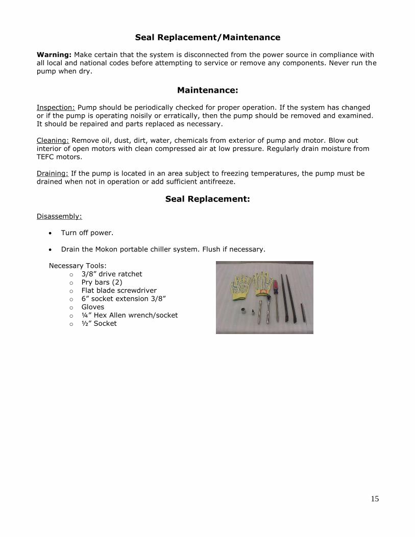
Necessary Tools:
o 3/8” drive ratchet
o Pry bars (2) o Flat blade screwdriver
o 6” socket extension 3/8”
o Gloves
o ¼” Hex Allen wrench/socket
o ½” Socket

16
Remove pump/motor from cabinet.
Remove casing screws and remove case.
Inspect o-ring for wear or damage.
Remove the cap at the lead end of the motor. A screwdriver slot
will be exposed. Use a screwdriver to stop the shaft from
turning.
Caution: Do not insert screwdriver between impeller vanes to prevent rotation. This can damage the impeller.
Remove the impeller lock nut and washers by turning counter
clockwise when looking at the front of the pump.
Remove the impeller by turning counter clockwise. Protect the
hand by wearing a glove.
Caution: Failure to remove the impeller in a counterclockwise direction may damage the threading on the impeller, the shaft or both.
17
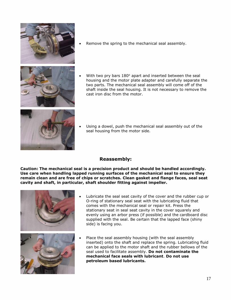
Remove the spring to the mechanical seal assembly.
With two pry bars 180o apart and inserted between the seal
housing and the motor plate adapter and carefully separate the
two parts. The mechanical seal assembly will come off of the
shaft inside the seal housing. It is not necessary to remove the
cast iron disc from the motor.
Using a dowel, push the mechanical seal assembly out of the
seal housing from the motor side.
Reassembly:
Caution: The mechanical seal is a precision product and should be handled accordingly.
Use care when handling lapped running surfaces of the mechanical seal to ensure they
remain clean and are free of chips or scratches. Clean gasket and flange faces, seal seat
cavity and shaft, in particular, shaft shoulder fitting against impeller.
Lubricate the seal seat cavity of the cover and the rubber cup or
O-ring of stationary seal seat with the lubricating fluid that
comes with the mechanical seal or repair kit. Press the
stationary seat in seal seat cavity in the cover squarely and
evenly using an arbor press (if possible) and the cardboard disc
supplied with the seal. Be certain that the lapped face (shiny
side) is facing you.
Place the seal assembly housing (with the seal assembly
inserted) onto the shaft and replace the spring. Lubricating fluid
can be applied to the motor shaft and the rubber bellows of the
seal used to facilitate assembly. Do not contaminate the
mechanical face seals with lubricant. Do not use
petroleum based lubricants.

18
Thread the impeller onto the shaft by turning clockwise. Protect
the hand with a glove. Prevent shaft rotation by using a
screwdriver on the shaft end screwdriver slot.
Replace the impeller lock nut and washer by turning clockwise.
Prevent shaft rotation by using a screwdriver on the shaft end
screwdriver slot.

19
Replace the casing and casing screws and tighten finger tight.
Finish tightening the cap screws alternately and evenly to
approximately 6 ft. lbs. torque.
Note: It is imperative that screws be tightened alternately and
evenly, as this action centers the cover in the casing, assuring
proper alignment. Binding of the impeller in the case and
adaptor may occur if the cap screws are not tightened as listed
above.
Check for free rotation then replace the cap at the rear of motor.
Reinstall pump/motor into system.
20
4.3 Glossary of Indicators, Gauges, and Buttons Supply Pumps Start/Stop Buttons: Pilot light illuminates green to supply pump
(chilled water circuit) to process is activated.
Compressor Start/Stop Buttons: Pilot light illuminates green to indicate
refrigeration loop and compressor pump is
activated.
No Flow Indicating Light: When illuminated indicates inadequate fluid
flow returning to the Iceman system to
ensure safe operation.
Freezestat Indicating Light: When illuminated, indicates compressor has
shut down due to coolant temperatures
below safe operation.
Low Refrigerant Pressure Indicating
Light:
When illuminated, indicates compressor has
shut down due to low refrigerant pressure.
High Refrigerant Pressure Indicating
Light:
When illuminated, indicates compressor has
shut down due to high refrigerant pressure.
Supply Pump Pressure Gauge: Indicates fluid pressure for the “chilled water
loop” going to the process.
Return Temperature Gauge: Indicates the temperature of “chilled water
loop” returning from the process.
High Refrigerant Pressure Gauge: Indicates the pressure of the refrigerant, as
it is being condensed in the condenser. This
pressure is critical to the performance of the
chiller and is generated by the compressor.
The normal pressure is between 200-300
PSIG/ 1379-2068 kPa (R-22/R-407C) or
110-230 PSIG/ 758-1586 kPa (R-134A)
(depending on load).
Low Refrigerant Pressure Gauge: Indicates compressor suction pressure and is
related to temperature setting and the
adequacy of refrigerant charge.

21
Section 5 – Eurotherm Controller (3000 Series)
5.1 Operation This section of the manual contains all essential information needed to operate the controller.
Contact Mokon Customer Service with controller problems as well as warranty and repair issues.
The controller is configured by model number. Inputs, outputs and alarm types are preset. Final
setup and configuration are done from the keypad. The controller has four basic modes: Operator
1, Operator 2, Operator 3 and the configuration mode.
The controller’s default level is Operator 1, and is used for day to day operation.
Note: Operator 2, 3 and configuration are password protected.
Home List Navigation To step through list levels press and hold the Page button until level 1 is obtained. Press the up
button or the down button to change levels.
To step through parameters within a particular list, press the Scroll button until the required
parameter is obtained.
To change the value (or state) of a parameter, press the Up button or the Down button.
*Refer to Section 5.1 Keys for button locations and descriptions.
Levels Operator 1
Parameter Mnemonic Scroll Function
WRK.OP
WORKING OUPUT The active output value
Output %
SP1 SETPOINT 1 -------
SP2 SETPOINT 2 -------
A1.High ALARM 1 SETPOINT
A2.Low ALARM 2 SETPOINT
* A3.xxx ALARM 3 SETPOINT
ID Customer ID Controller Revision #
*Optional

22
Keys
Note: Pictured is the 3216 Eurotherm controller - this also applies to 3204 and 3208 series
controllers.
Button or Indicator
Name
Explanation
OP1
Output 1
When lit, it indicates that alarm output is on. “FREEZE PROTECTION” will scroll.
OP2
Output 2
When lit, it indicates that alarm output is on. “HIGH FLUID TEMPERATURE” will scroll.
Page button Press to select a new list of parameters.
Scroll button Press to select a new parameter in a list.
Down button Press to decrease a value in the setpoint.
Up button Press to increase a value in the setpoint.
ALM Alarm Flashes when in alarm condition. “ALARM MESSAGE” will scroll.
OP4 Output 4 When lit indicates that the cooling output is on. “COOLING” will scroll.

23
5.2 Troubleshooting Diagnostic Alarms:
Display Shows
What it means
What to do about it E.ConF A change made to a
parameter takes a finite
time to be entered. If the
power to the controller is
turned off before the
change has been entered
then this alarm will occur.
Do not turn the power off
to the controller while ConF
is flashing.
Enter configuration mode
then return to the required
operating mode. It may be
necessary to re-enter the
parameter change since it
will not have been entered
in the previous
configuration.
E.CAL Calibration error Re-instate Factory
calibration
E2.Er EEPROM error Return to factory for repair
EEEr Non-vol memory error Note the error and contact
your supplier
E.Lin Invalid input type. This
refers to custom
linearization which may not
have been applied corrector
or may have been
corrupted.
Go to the INPUT list in
configuration level and set a
valid thermocouple or input
type.
Note: Some error messages may not appear, depending on the controller options.
5.3 Alarm Indicators
ALM beacon flashing red = a new alarm (unacknowledged).
This is accompanied by a scrolling alarm message. A typical default message will show the
source of the alarm followed by the type of alarm. For example, “FREEZE PROTECTION” and
“HIGH FLUID TEMPERATURE”.
If more than one alarm is present further messages are flashed in turn in the main display.
The alarm indication will continue while the alarm condition is present and is not
acknowledged.
ALM beacon on continuously = alarm has been acknowledged.
24
To Acknowledge an Alarm
Press and together.
Non-Latched Alarms
Alarm condition present when the alarm is acknowledged.
ALM beacon on continuously.
The alarm message(s) will continue to scroll.
This state will continue for as long as the alarm condition remains. When the alarm condition
disappears all indication also disappears.
If the alarm condition disappears before it is acknowledged the alarm reset immediately.
5.4 Remote Setpoint and Retransmission “Scaling” Scaling of the 4-20mA and 0-10V signals for this option are as follows:
4mA or 0V = minimum system operating temperature.
20mA or 5V, 10V = maximum system operating temperature.
Note: Maximum system operating temperature value is reflective of the series system purchased,
(refer to serial tag for maximum operating temperature located on Mokon system).
Consult customer service at Mokon factory (716) 876-9951, regarding system’s minimum and
maximum temperatures if there are any questions.

25
Section 6 – Options
6.1 Air Duct Flange (Top)
This option allows the user to run duct work with a blower fan to the top of the air-cooled unit to
draw the heat generated by the cooling process out of the room (area) where the chiller is located.
The flange, placed by Mokon, will be sized per the unit. The customer will need to provide and
install the accompanying duct work as well as the blower fan. The blower fan must be sized so
that it delivers 1,000 cfm (minimum) per chiller ton of air flow for the proper ventilation (heat
removal) of the chiller. Anything less will result in the chiller overheating and will shut down the
unit.
6.2 Automatic Fill with Low Water Level Indication
As stated in Section 2.6, the reservoir tank must maintain a minimum of ¾ total fluid capacity.
This option provides for automatic monitoring and filling of the reservoir. Connect a constant
supply water source to the ½” NPT tank connection at the back of the unit and leave on. When the
level gets below the ¾ minimum, the Low Level light on the front of the electrical panel will come
on and the unit, via a float switch, will fill to the required level. The light will then turn off. Keep in
mind, use of glycol IS REQUIRED FOR OPERATION BELOW 45oF AND MUST BE MANUALLY ADDED
TO THE TANK. The table in Section 2.6 lists the correct glycol/water mixtures for operating at
temperatures below 45oF.
6.3 Crankcase Pressure Relief (CPR) Valve
The chiller generally operates with a set point anywhere between 50° F (10° C) and 65° F (18.3°
C) allowing for a return fluid temperature of up to 75° F (23.9° C). If it is desired to run the chiller
temperature set point above 65° F (18.3° C) then a CPR valve is required. This regulating valve
helps to maintain the proper suction pressure of the crankcase of the compressor so as not to
overload the compressor motor. Even with the CPR valve, the maximum allowable temperature set
point on a chiller is 85° F (29.4° C) with an assumed return fluid temperature of 95° F (35° C). At
no time should the return fluid temperature to the chiller ever exceed 95° F (35° C)! This CPR
valve is factory set and must never be adjusted by the customer!!
6.4 Digital Flow Meter
This optional feature provides for a Blancett 1100 Series Turbine Flow Meter with flow indication on
the “TO” Process line of each zone. See the CD for the flow meter Data Sheet and Manual.
6.5 Emergency Stop The emergency stop device will shut the machine down regardless of the operating mode. Once the
emergency stop device has been activated, it must be disengaged by turning the button clockwise.
Disengaging the emergency stop will not restart the machinery but only permit restarting.
Per the risk assessment of the machine, the emergency stop is not wired to a safety rated
relay.
Do not wire additional safety components to the Mokon stop relay or modification of the
emergency stop circuit is prohibited.
26
6.6 Overhead Piping Kit
This option is required when the process and/or process piping is above the level of the unit and
the volume is such that the total amount of fluid (water/water & glycol) used exceeds the capacity
of the unit reservoir. Upon unit shut-down, the swing check valve(s) and the spring check valve(s)
within the unit will prevent backflow of fluid from the process loop into the unit reservoir thereby
avoiding an overflow condition.
6.7 Process Purge Option (Air Connections)
To facilitate mold changes with a minimum amount of oil loss from the hoses and the process, a
process purge system via air is provided as an option.
Note: If additional fluid has been added to the Mokon system after initial start up, it will be
necessary to drain the excess fluid prior to using the process purge as to avoid overflowing the
reservoir tank.
The following is the procedure to utilize this process purge option:
Turn the controller to the minimum setting and wait until the process temperature is below
130F. (See Section 5 for Controller Instructions)
Shut off the zone by pressing the “Stop” button.
Connect the Air Supply to the Air Inlet on the system.
Warning: Air supply pressure should not exceed 15 PSIG (103 kpa).
Depress the “Process Purge” button on the control panel.
The fluid in the process loop will be returned to the reservoir.
Repeat steps 1 – 4 for each system.
Refer to Section 3.1 to Restart the System.
Note: The time required to purge the system is based on the holdup volume of the process and the
air supply to the system.
6.8 Valved Process Bypass This option is simply a direct fluid path between the “TO” process line and the “FROM” process line
that will allow you to bypass your process partially or completely via a metered globe valve on the
outside back of the unit. This provides a means of controlling the amount of flow out to the
process should you wish to reduce it from the normally full flow condition.

27
6.9 “Z” Purge Instructions for Mokon Portable Chiller Systems
A 3 inch diameter threaded pipe connection is provided to receive an air or nitrogen supply,
a 90 cfm blower is recommended. This blower shall not be installed or placed in the
hazardous environment where hazardous fumes will be drawn from for supply air to the
electrical enclosure or internal cabinetry of the Mokon system. The optimum nitrogen or air
supply range to the Mokon system should be .15 to .5 inches of water column.
As an alternative to nitrogen, non-hazardous “clean” dry air can be supplied which can also
include clean dry compressed shop air.
The discharge pressure of the fan or blower needs to be, at least, 3.0 inches of water
column for every 100 equivalent feet of 3” duct. For 4” duct, 1.0 inch of water column per
100 feet is adequate. A 3” exhaust connection is also provided.
Note: Due to temperature considerations, the purge gas must flow (sweep) through the
unit to insure adequate ventilation.
Once the purge gas is introduced, the Dwyer model 1950-0-2F pressure switch will close,
energizing a time delay relay. The relay prevents startup of the Mokon system until an
adequate sweep inside the unit has taken place. The switch is set at its minimum setting of
0.15 inches of water. A green pilot light will illuminate once the relay has “timed out”,
indicating it is safe to operate the unit.
The magnehelic gauge has a scale of 0 to .5 inches of water, and is clearly visible to allow
the operator to monitor the unit.
If the purge is lost, for any reason, the pressure switch will open, thus activating a customer
supplied alarm through a set of auxiliary contacts. The Mokon system will also shut off.
For systems that are classified and applied properly the applicable Class, Group and Division
is listed on the bottom of the systems serial tag.
Methods: There are typically two methods for the supply of purge gas to systems for “Z”
purge applications, they are as follows:
Method # 1 (recommended): Due to temperature considerations, the purge gas must
flow (sweep) through the unit to insure adequate ventilation. This method would apply
to water, oil, chiller, and full range heater/chiller systems.
Method # 2: (not recommended): Pressurization of the cabinetry when temperature
build up is not as much of a concern can be applied. Here the exhaust coupling on the
cabinet would be plugged. This method would apply to water-cooled chiller systems or
very low heating capacity systems.
Note: If the “Z” purge mechanism or any other system safety devices are modified or
disable in any way Mokon considers them to be non-operational and the systems warranty
could be void.

28
Section 7 – Troubleshooting Guide
7.1 Process Loop
Problem Possible Cause Corrective Measure
System unplugged / power
off
Plug system in / turn power
on
Improper power source
wiring
Check wiring (electrical
schematics) and correct
Blown fuse at power supply Isolate open fuse and
replace
Blown control circuit fuse Replace and check for
ground condition
Low voltage Measure incoming voltage,
if too low correct
Overload on pump/motor
starter Consult factory
Inadequate flow of process
fluid
Inspect process and process
lines for blockage; if
blocked correct
Flow switch Inspect/replace component
Overload on pump/motor
starter Consult factory
Blown fuse at power supply Isolate open fuse and
replace
Blown control circuit fuse Replace and check for
ground condition
Faulty seal
Improperly aligned seal
Over-pressured seal
Float switch Inspect; if stuck, replace
Solenoid diaphragm will not
seat Inspect/replace

29
7.2 Refrigeration Loop Only a qualified refrigeration technician should attempt repairs in the refrigeration
loop.
Problem Possible Cause Corrective Measure
Process fluid temperature
below set point Change set point
Scroll compressor rotating
in the wrong direction Consult Mokon factory
Low or high refrigerant
pressure
Consult a Qualified
Refrigeration Technician
Compressor shut down due
to thermal protection
Let cool, restart, and verify
amp draw
Inadequate flow of process
fluid
Inspect process and lines
for blockage, clear blockage
if necessary
Controller or thermostat
(controller optional on 1/2
and 1 ton systems)
Consult factory (DO NOT
attempt repairs, this will
VOID your warranty!)
Freezestat Inspect/replace
Blown control circuit fuse Replace and check for
ground condition
Low water flow through the
condenser
Verify condenser supply
water flow rate is as stated
in Section 2.5
Water regulating valve Inspect/clean or replace
Condenser supply water
lines too small
Replace lines with insulated
hose or pipe of equal
diameter as the port
Insufficient water pressure
drop across condenser due
to plugged or fouled
condenser tubes
Inspect/clean or replace
Condenser supply water
temperature too high
(above 85oF / 29oC)
Find colder source of water
Dirty condenser coils Inspect/clean
Fan rotation Verify fan is rotating
(counterclockwise)
Blown control fuse
Fan limit switch – Consult
Qualified Refrigeration
Technician
High ambient air
temperature
Find a cooler source or
force
more air
Refrigeration loop
overcharged
Consult a Qualified
Refrigeration Technician

30
Problem Possible Cause Corrective Measure
Low refrigerant charge
Low head pressure
Restriction to refrigerant
flow in refrigerant loop
Ambient air temperature
too cold (air-cooled) Find warmer source of air
Condenser cooling water
temperature too low
(water-cooled)
Find warmer source of water
Air in process loop Purge – See Start Up Procedure
in Section 3.1
Water/glycol solution
foaming Replace water/glycol mixture
Attempting to operate
below setting (45oF/7oC) Consult Mokon factory
Freezestat Inspect/replace
Low water flow causing
icing in condenser (water
cooled)
Hot gas bypass valve
stuck open
Condenser tubes limed
over/blocked (water
cooled)
Poor condensing
Over condensing
Bad valves in compressor
Chiller not started
correctly (before heat
generating process)
See Section 3.1 for Correct
Starting Procedure
Scroll compressor
rotating in the wrong
direction
Consult Mokon factory
Chiller undersized for
load Consult Mokon engineering
Lack of refrigerant
Dryer clogged
Too large process load
Evaporator freezing
Restrictive process or
process connections Remove restrictions
Thermocouple or RTD Inspect/replace component
Controller calibration See Controller Section 5

31
Section 8 – Condensed Parts List
½ - 10 Ton Systems:
Part No Description
006256 Motor starter/24 amp heater contactor 110V coil (pump/motor)
006257 40 amp heater contactor 110V coil (compressor)
006366 1.0 – 5.0 amp overload
006367 3.2 – 16 amp overload
008021 0 – 160 PSI pressure gauge, suction, and discharge
018246 Seal kit for pump/motor assembly
022038 Start/stop button
023089 Thermometer
040002 Thermocouple
15 and 20 Ton Systems:
Part No Description
006256 Motor starter/24 amp heater contactor 110V coil (pump/motor)
006257 40 amp contactor 110V coil (compressor)
006298 50 amp contactor 110V coil (compressor)
006366 1.0 – 5.0 amp overload
008021 0 – 160 PSI pressure gauge, suction, and discharge
018246 Seal kit for pump/motor assembly
022038 Start/stop button
023089 Thermometer
040002 Thermocouple
25, 30 and 40 Ton Systems:
Part No Description
006256 Motor starter/24 amp heater contactor 110V coil (pump/motor)
006306 65 amp contactor (40 Ton x 2)
006308 120 amp contactor (25 & 30 Ton)
006367 3.2 – 16 amp overload (25 & 30 Ton)
006368 5.4 – 27 amp overload (40 Ton)
008021 0 – 160 PSI pressure gauge, suction, and discharge
018246 Seal kit for pump/motor assembly (25 Ton)
018406 Seal kit for pump/motor assembly (30 & 40 Ton)
022038 Start/stop button
040026 Thermocouple
For additional part numbers refer to the specific section in the instruction manual or consult the
Mokon factory (716) 876-9951.

32
Section 9 – Warranty
ICEMAN PORTABLE CHILLER WARRANTY
All new ICEMAN CHILLER systems manufactured by MOKON are guaranteed to be free from
defective material or workmanship for one (1) year from the date of purchase. All Standard
Microprocessor controllers carry a five (5) year warranty, Microprocessors with special features
carry a three (3) year warranty and Solid State controllers carry a one (1) year warranty. MOKON'S
obligation under the WARRANTY SHALL BE LIMITED, TO THE ORIGINAL CUSTOMER, TO REPAIR OR
REPLACE DEFECTIVE PART(S) OF THE TEMPERATURE CONTROL SYSTEM, and UPON CUSTOMER
COMPLIANCE WITH THE INSTRUCTIONS CONTAINED HEREIN. Upon discovery of any alleged
defect, it is the responsibility of the customer to contact the MOKON Service Department with the
complete model number, serial number and the date of purchase. MOKON’S obligation under this
warranty is limited to make good, from or at its factory, any parts that are returned to the
company (prepaid) and deemed to defective, within the time frame of the warranty. The customer
also has the option of forwarding the system to MOKON (Buffalo, NY), prepaid by the customer and
with a return authorization from MOKON for inspection and component replacement or repair.
Repair or replacement in any manner provided above shall constitute a fulfillment of all liabilities of
MOKON concerning the quality of the temperature control system. Freeze-ups of any kind are not
covered under this warranty.
No allowances, credits or reimbursements will be made for any replacement or repair made or
provided for by the customer unless authorized in advance, in writing, by MOKON.
Note: The use of automotive anti-freeze in a chiller system will void the above warranty!
The warranty set forth above is in lieu of any and all other warranties expressed or implied including
warranties of merchantability and fitness for a particular purpose. Mokon shall in no event be liable
for any consequential damages or for any breach of warranty in an amount exceeding the original
price of the unit.
Mokon’s products are not guaranteed against damage caused by corrosion.
2150 Elmwood Avenue - Buffalo, NY 14207
P# 716-876-9951 - F#716-874-8048 - www.mokon.com