Embed Size (px)
Citation preview
8.914-401.0
SERIAL NUMBER:
DATE PURCHASED:
FOR SALES AND SERVICE, PLEASE CONTACT:
®cLISTED ®
OPERATING INSTRUCTIONS AND PARTS MANUAL
Thank you for purchasing a Hotsy Pressure Washer. This manual covers the operation and main te -nance of your pressure washer. All information in this manual is based on the latest product in for ma -tion available at the time of printing. Hotsy, Inc. reserves the right to make changes at any time without incurring any obligation.
Read in struc tions care ful ly before at tempt ing to as sem ble, install, op er ate or service this pres sure washer. Failure to comply with in struc tions could result in personal in ju ry and/or prop er ty damage!
MODELS 965SS, 1065SS,1065SSE, 1075SSE
HOTSY 965SS-1075SS • 8.914-401.0 • Rev. 09/11
3
PR
ES
SU
RE
WA
SH
ER
OP
ER
ATO
R’S
MA
N U
AL
965SS SPECIFICATIONS
● Pump Volume At Pump Head: 3.0 GPM/180 GPH● Pump Pressure At Pump Head: 3000 PSI● Burner Type: Fuel Oil Fired, 248,000 BTU/Hr.● Burner Fuel Pressure: 140 PSI● Machine Displacement: 270cc● Exhaust Stack Size: 8"● Machine Dimensions: Length=47", Width=31", Height=47"
1065SS SPECIFICATIONS● Pump Volume At Pump Head: 3.5 GPM/210 GPH● Pump Pressure At Pump Head: 3000 PSI● Burner Type: Fuel Oil Fired, 309,900 BTU/Hr.● Burner Fuel Pressure: 160 PSI● Machine Displacement: 337cc● Exhaust Stack Size: 8"● Machine Dimensions: Length=47", Width=31", Height=49"
1065SSE SPECIFICATIONS● Pump Volume At Pump Head: 3.5 GPM/210 GPH● Pump Pressure At Pump Head: 3000 PSI● Burner Type: Fuel Oil Fired, 309,900 BTU/Hr.● Burner Fuel Pressure: 160 PSI● Machine Displacement: 389cc Electric Start● Exhaust Stack Size: 8"● Machine Dimensions: Length=47", Width=31", Height=49"
1075SSE SPECIFICATIONS● Pump Volume At Pump Head: 3.8 GPM/228 GPH● Pump Pressure At Pump Head: 3500 PSI● Burner Type: Fuel Oil Fired, 309,900 BTU/Hr.● Burner Fuel Pressure: 160 PSI● Machine Displacement: 389cc Electric Start● Exhaust Stack Size: 8"● Machine Dimensions: Length=47", Width=31", Height=49"
CONTENTS
4
HOTSY 965SS-1075SS • 8.914-401.0 • Rev. 05/11
Model Number ______________________________
Serial Number ______________________________
Date of Purchase ____________________________
The model and serial numbers will be found on a decal at tached to the pressure washer. You should record both serial number and date of purchase and keep in a safe place for future ref er ence.
Important Safety Information 5-7
Component Identifi cation 8
Assembly Instructions 9-10
Installation Instructions 11
Operation Instructions 12-13
General Cleaning Techniques & Storage 14
Maintenance 15
Troubleshooting 16-17
Warranty 35
HOTSY 965SS-1075SS • 8.914-401.0 • Rev. 09/11
5
PR
ES
SU
RE
WA
SH
ER
OP
ER
ATO
R’S
MA
N U
AL
INTRODUCTION & IMPORTANT SAFETY INFORMATION
Thank you for purchasing this Pressure Washer.
We reserve the right to make changes at any time without incurring any obligation.
Owner/User Responsibility:The owner and/or user must have an understanding of the manufacturer’s operating instructions and warnings before using this pressure washer. Warning information should be emphasized and understood. If the operator is not fl uent in English, the manufacturer’s instructions and warnings shall be read to and discussed with the operator in the operator’s native language by the purchaser/owner, making sure that the operator com-prehends its contents.
Owner and/or user must study and maintain for future reference the manufacturers’ instructions.
The operator must know how to stop the machine quickly and understand the operation of all controls. Never permit anyone to operate the engine without proper instructions.
This manual should be considered a permanent part of the machine and should remain with it if machine is resold.
When ordering parts, please specify model andserial number. Use only identical replacement parts.
This machine is to be used only by trained op-erators.
IMPORTANT SAFETY INFORMATION
READ OPERATOR’S MANUAL THOROUGHLY
PRIOR TO USE.
WARNING: To reduce the risk of injury, read operating instruc-tions carefully before using. 1. Read the owner's manual
thoroughly. Failure to follow instructions could cause malfunction of the machine and result in death, serious bodily injury and/or property damage.
2. Know how to stop the machine and bleed pressure quickly. Be thoroughly familiar with the controls.
3. Stay alert — watch what you are doing.
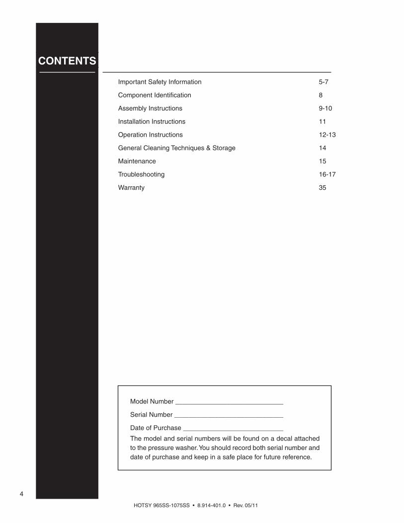
WARNING
KEEP WATERSPRAY AWAY FROM
ELECTRICAL WIRING.
WARNING: Keep wand, hose, and water spray away from electric wiring or fatal electric shock may result.
4. All installations must comply with local codes. Contact your electrician, plumber, utility company or the selling distributor for specifi c details.
WARNING
EAR PROTECTION MUST BE WORN
WARNING: This machine exceeds 85 db appropriate ear protection must be worn.
WARNING
USE PROTECTIVE EYE WEAR
AND CLOTHING WHEN OPERATINGTHIS EQUIPMENT.
WARNING: High pressure spray can cause paint chips or other particles to become airborne and fl y at high speeds. To avoid personal injury, eye, hand and foot safety devices must be worn. 5. Eye, hand, and foot protection
must be worn when using this equipment.
6. Keep operating area clear of all persons.
RISK OF EXPLOSION: OPERATE ONLY WHERE OPEN FLAME OR TORCH
IS PERMITTED
WARNINGWARNING: Flammable liquids can create fumes which can ig-nite, causing property damage or severe injury.
WARNING: Risk of explosion — Operate only where open fl ame or torch is permitted.
RISK OF FIRE. DO NOT ADD FUEL WHEN OPERATING
MACHINE.
WARNING WARNING: Risk of fi re — Do not add fuel when the product is operating or still hot.
WARNING: Do not use gasoline crankcase draining or oil con-taining gasoline, solvents or alcohol. Doing so will result in fi re and/or explosion.
WARNING: Risk of fi re — Do not Spray fl ammable liquids.
WARNING: This product contains chemicals known to the state of California to cause cancer and birth
HOTSY 965SS-1075SS • 8.914-401.0 • Rev. 09/11
OP
ER
ATO
R’S
MA
NU
AL
P
RE
SS
UR
E W
AS
HE
R
6
HOT DISCHARGE FLUID: DO NOT TOUCH OR
DIRECT DISCHARGE STREAM AT PERSONS.
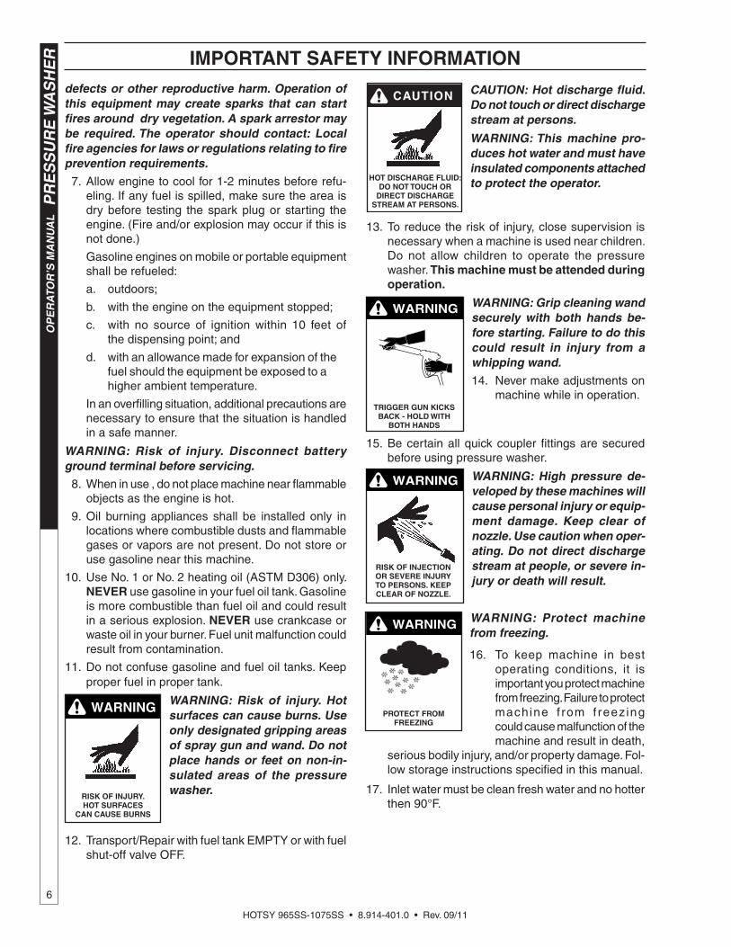
CAUTION: Hot discharge fl uid. Do not touch or direct discharge stream at persons.
WARNING: This machine pro-duces hot water and must have insulated components attached to protect the operator.
13. To reduce the risk of injury, close supervision is necessary when a machine is used near children. Do not allow children to operate the pressure washer. This machine must be attended during operation.
TRIGGER GUN KICKS BACK - HOLD WITH
BOTH HANDS
WARNING WARNING: Grip cleaning wand securely with both hands be-fore starting. Failure to do this could result in injury from a whipping wand.14. Never make adjustments on
machine while in operation.
15. Be certain all quick coupler fi ttings are secured before using pressure washer.
RISK OF INJECTION OR SEVERE INJURY TO PERSONS. KEEP CLEAR OF NOZZLE.
WARNING WARNING: High pressure de-veloped by these machines will cause personal injury or equip-ment damage. Keep clear of nozzle. Use caution when oper-ating. Do not direct discharge stream at people, or severe in-jury or death will result.
WARNING
PROTECT FROM FREEZING
WARNING: Protect machine from freezing.
16. To keep machine in best operating conditions, it is important you protect machine from freezing. Failure to protect machine f rom f reez ing could cause malfunction of the machine and result in death,
serious bodily injury, and/or property damage. Fol-low storage instructions specifi ed in this manual.
17. Inlet water must be clean fresh water and no hotter then 90°F.
IMPORTANT SAFETY INFORMATIONdefects or other reproductive harm. Operation of this equipment may create sparks that can start fi res around dry vegetation. A spark arrestor may be required. The operator should contact: Local fi re agencies for laws or regulations relating to fi re prevention requirements.
7. Allow engine to cool for 1-2 minutes before refu-eling. If any fuel is spilled, make sure the area is dry before testing the spark plug or starting the engine. (Fire and/or explosion may occur if this is not done.)
Gasoline engines on mobile or portable equipment shall be refueled:
a. outdoors;
b. with the engine on the equipment stopped;
c. with no source of ignition within 10 feet of the dispensing point; and
d. with an allowance made for expansion of the fuel should the equipment be exposed to a higher ambient temperature.
In an overfi lling situation, additional precautions are necessary to ensure that the situation is handled in a safe manner.
WARNING: Risk of injury. Disconnect battery ground terminal before servicing. 8. When in use , do not place machine near fl ammable
objects as the engine is hot.
9. Oil burning appliances shall be installed only in locations where combustible dusts and fl ammable gases or vapors are not present. Do not store or use gasoline near this machine.
10. Use No. 1 or No. 2 heating oil (ASTM D306) only. NEVER use gasoline in your fuel oil tank. Gasoline is more combustible than fuel oil and could result in a serious explosion. NEVER use crankcase or waste oil in your burner. Fuel unit malfunction could result from contamination.
11. Do not confuse gasoline and fuel oil tanks. Keep proper fuel in proper tank.
WARNING
RISK OF INJURY. HOT SURFACES
CAN CAUSE BURNS
WARNING: Risk of injury. Hot surfaces can cause burns. Use only designated gripping areas of spray gun and wand. Do not place hands or feet on non-in-sulated areas of the pressure washer.
12. Transport/Repair with fuel tank EMPTY or with fuel shut-off valve OFF.

HOTSY 965SS-1075SS • 8.914-401.0 • Rev. 09/11
7
PR
ES
SU
RE
WA
SH
ER
OP
ER
ATO
R’S
MA
N U
AL
IMPORTANT SAFETY INFORMATION
WARNING
RISK OFASPHYXIATION: USE THIS PRODUCT ONLY
IN A WELLVENTILATED AREA.
WARNING: Risk of asphyxiation. Use this product only in a well ventilated area. 18. Avoid installing machines in
small areas or near exhaust fans. Adequate oxygen is needed for combustion or dangerous carbon monoxide will result.
19. Manufacturer will not be liable for any changes made to our standard machines or any compo-nents not purchased from us.
20. The best insurance against an accident is precau-tion and knowledge of the machine.
WARNING
RISK OF INJURY FROM FALLS WHEN
USING LADDER.
WARNING: Be extremely careful when using a ladder, scaffold-ing or any other relatively un-stable location. The cleaning area should have adequate slopes and drainage to reduce the possibility of a fall due to slippery surfaces.
21. Do not allow acids, caustic or abrasive fl uids to pass through the pump.
22. Never run pump dry or leave spray gun closed longer than 1-2 minutes.
23. Machines with shut-off spray gun should not be operated with the spray gun in the off position for extensive periods of time as this may cause dam-age to the pump.
24. Protect discharge hose from vehicle traffi c and sharp objects. Inspect condition of high pressure hose before using or bodily injury may result.
25. Before disconnecting discharge hose from water outlet, turn burner off and open spray gun to al-low water to cool below 100° before stopping the machine. Then open the spray gun to relieve pres-sure. Failure to properly cool down or maintain the heating coil may result in a steam explosion.
26. Do not overreach or stand on unstable support. Keep good footing and balance at all times.
27. Do not operate this machine when fatigued or under the infl uence of alcohol, prescription medi-cations, or drugs.
28. In oil burning models, use only kerosene, No. 1 home heating fuel, or diesel. If diesel is used, add a soot remover to every tankful.
Follow the maintenance instructions specifi ed in the manual.

HOTSY 965SS-1075SS • 8.914-401.0 • Rev. 09/11
OP
ER
ATO
R’S
MA
NU
AL
P
RE
SS
UR
E W
AS
HE
R
8
COMPONENT IDENTIFICATION
Pump — Delivers a specifi c gpm to the high pressure nozzle which develops pressure.
Spray Gun — Controls the application of water and de ter gent onto cleaning surface with trigger device. In cludes safe ty latch.
Detergent Injector — Allows you to siphon and mix detergents.
Wand — Must be connected to the spray gun.
High Pressure Hose — Connect one end to water pump high pressure discharge nipple and the other end to spray gun.
Unloader Valve — Safety device which, when the spray gun closes, redirects fl ow of water.
Note: If trigger on spray gun is released for more than 2 minutes, water may leak from the pump pro tec tor. Warm wa ter will dis charge from pump pro tec tor onto fl oor. This sys tem pre vents internal pump dam age.
Pump
Unloader Valve
Detergent Injector
SprayGun
HighPressure Hose
Wand
Burner ExhaustCoil Outlet
Hose Hanger
Engine
High Pressure
Nozzle
HOTSY 965SS-1075SS • 8.914-401.0 • Rev. 09/11
9
PR
ES
SU
RE
WA
SH
ER
OP
ER
ATO
R’S
MA
N U
AL
ASSEMBLY INSTRUCTIONS
UnpackingUnpack carefully. Wear safety glasses or goggles while unpacking, assembling, or operating pres sure washer. If there are missing components or hidden damage, im me di ate ly contact carrier concerning dis crep an cies.
1. Cut strapping band from pressure washer and pal-let.
2. Remove pressure washer from pallet.
Parts Included• Pressure Washer
• Pressure Hose
• Wand
• Operating Instructions and Parts Manual
• Gasoline Engine Manual
• Parts Bag Containing:■ Pressure Nozzles (3 Ea.)■ Trigger Gun■ Battery Terminals (2 Ea.)
Tools Required• 8" Adjustable Wrench
• Tefl on Tape
• Flat Blade Screwdriver
Pressure Hose, Trigger Gun and Wand1. When assembling, use tefl on tape on all thread ed
plumb ing connections to prevent leakage.2. Install the pressure hose on the pressure washer as
shown in Figure 1.
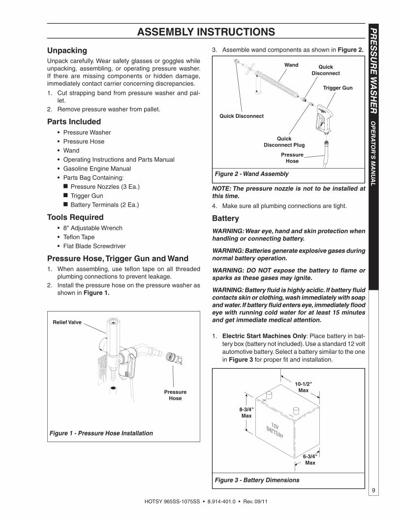
3. Assemble wand components as shown in Figure 2.
NOTE: The pressure nozzle is not to be installed at this time.
4. Make sure all plumbing connections are tight.
Battery
WARNING: Wear eye, hand and skin protection when handling or connecting battery.
WARNING: Batteries generate explosive gases dur ing normal battery operation.
WARNING: DO NOT expose the battery to fl ame or sparks as these gases may ignite.
WARNING: Battery fl uid is highly acidic. If battery fl u id contacts skin or clothing, wash immediately with soap and water. If battery fl uid enters eye, im me di ate ly fl ood eye with running cold water for at least 15 minutes and get immediate medical attention.
1. Electric Start Machines Only: Place battery in bat -tery box (bat tery not in clud ed). Use a standard 12 volt au to mo tive bat tery. Select a bat tery similar to the one in Figure 3 for prop er fi t and installation.
Figure 2 - Wand Assembly
Trigger Gun
Quick Disconnect
Quick Disconnect
Wand
QuickDisconnect Plug
Pressure Hose
Figure 3 - Battery Dimensions
6-3/4"Max
10-1/2"Max
8-3/4"Max
Relief Valve
Figure 1 - Pressure Hose Installation
Pressure Hose
HOTSY 965SS-1075SS • 8.914-401.0 • Rev. 09/11
OP
ER
ATO
R’S
MA
NU
AL
P
RE
SS
UR
E W
AS
HE
R
10
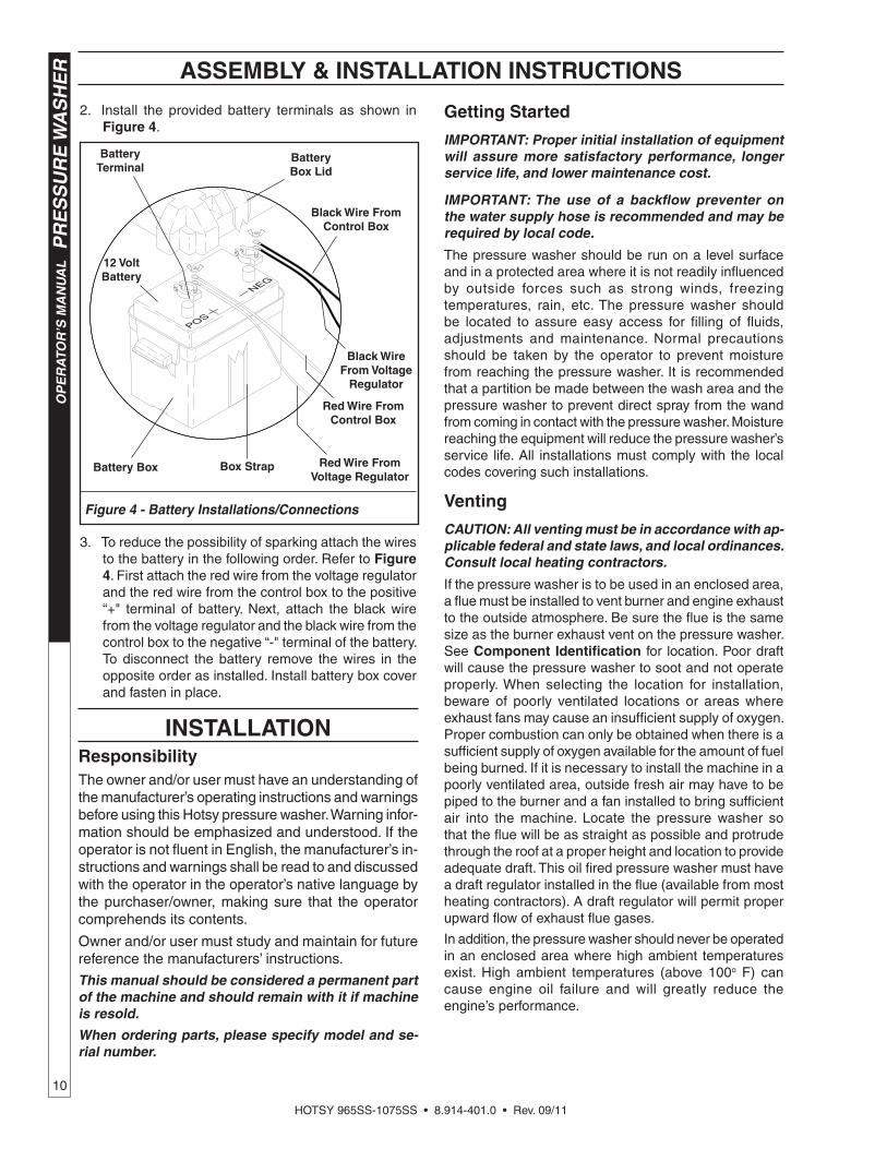
2. Install the pro vid ed battery ter mi nals as shown in Figure 4.
3. To reduce the pos si bil i ty of spark ing attach the wires to the battery in the fol low ing order. Re fer to Figure 4. First attach the red wire from the voltage reg u la tor and the red wire from the control box to the pos i tive “+" ter mi nal of bat tery. Next, attach the black wire from the voltage regulator and the black wire from the con trol box to the negative “-" terminal of the battery. To dis con nect the battery remove the wires in the op po site order as installed. Install bat tery box cover and fasten in place.
Figure 4 - Battery Installations/Connections
Box Strap
Battery Box Lid
Red Wire From Control Box
Black Wire From Voltage
Regulator
Red Wire From Voltage Regulator
12 Volt Battery
Battery Terminal
Battery Box
Black Wire From Control Box
ASSEMBLY & INSTALLATION INSTRUCTIONS
INSTALLATIONResponsibilityThe owner and/or user must have an un der stand ing of the man u fac tur er’s operating instructions and warn ings be fore us ing this Hotsy pressure washer. Warn ing in for -ma tion should be em pha sized and understood. If the op er a tor is not fl uent in En glish, the man u fac tur er’s in- struc tions and warnings shall be read to and dis cussed with the op er a tor in the operator’s native lan guage by the pur chas er/owner, making sure that the operator com pre hends its contents.
Owner and/or user must study and maintain for fu ture ref er ence the man u fac tur ers’ in struc tions.
This manual should be considered a per ma nent part of the machine and should remain with it if machine is re sold.
When ordering parts, please specify mod el and se -ri al number.
Getting Started
IMPORTANT: Proper initial installation of equip ment will assure more satisfactory per for mance, longer service life, and lower main te nance cost.
IMPORTANT: The use of a backfl ow preventer on the water supply hose is recommended and may be required by local code.
The pressure washer should be run on a level sur face and in a protected area where it is not readily infl uenced by out side forces such as strong winds, freezing tem per a tures, rain, etc. The pressure wash er should be located to assure easy access for fi lling of fl uids, adjustments and main te nance. Normal pre cau tions should be taken by the op er a tor to pre vent moisture from reaching the pressure washer. It is rec om mend ed that a par ti tion be made between the wash area and the pressure washer to prevent di rect spray from the wand from coming in contact with the pressure washer. Moisture reaching the equip ment will reduce the pressure washer’s service life. All installations must com ply with the local codes covering such installations.
Venting
CAUTION: All venting must be in accordance with ap-plicable fed er al and state laws, and local or di nanc es. Consult local heating con trac tors.
If the pressure washer is to be used in an enclosed area, a fl ue must be installed to vent burner and en gine exhaust to the outside atmosphere. Be sure the fl ue is the same size as the burner exhaust vent on the pressure washer. See Component Identifi cation for location. Poor draft will cause the pressure wash er to soot and not operate properly. When selecting the location for in stal la tion, beware of poorly ventilated lo ca tions or areas where exhaust fans may cause an in suf fi cient supply of oxygen. Proper combustion can only be ob tained when there is a suffi cient supply of oxygen avail able for the amount of fuel being burned. If it is necessary to install the machine in a poorly ven ti lat ed area, outside fresh air may have to be piped to the burner and a fan installed to bring suffi cient air into the machine. Locate the pressure washer so that the fl ue will be as straight as pos si ble and protrude through the roof at a proper height and location to provide adequate draft. This oil fi red pressure wash er must have a draft regulator installed in the fl ue (avail able from most heating contractors). A draft reg u la tor will permit prop er upward fl ow of exhaust fl ue gases.
In addition, the pressure washer should never be operated in an enclosed area where high ambient temperatures ex ist. High ambient temperatures (above 100o F) can cause engine oil failure and will greatly reduce the engine’s performance.
HOTSY 965SS-1075SS • 8.914-401.0 • Rev. 09/11
11
PR
ES
SU
RE
WA
SH
ER
OP
ER
ATO
R’S
MA
N U
AL
INSTALLATION INSTRUCTIONS
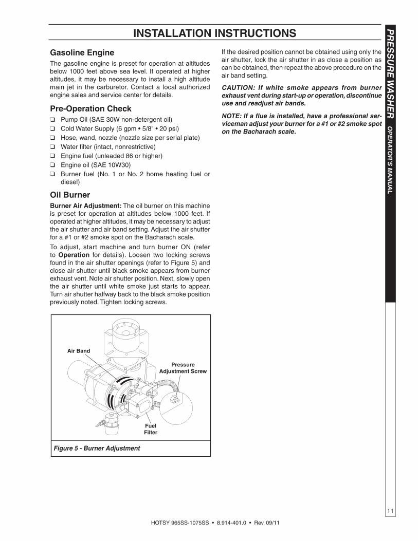
Figure 5 - Burner Adjustment
Air Band
PressureAdjustment Screw
Fuel Filter
Gasoline EngineThe gasoline engine is preset for operation at al ti tudes be low 1000 feet above sea level. If operated at higher al ti tudes, it may be necessary to install a high altitude main jet in the carburetor. Contact a local au tho rized engine sales and service center for details.
Pre-Operation Check❑ Pump Oil (SAE 30W non-detergent oil)❑ Cold Water Supply (6 gpm • 5/8" • 20 psi)❑ Hose, wand, nozzle (nozzle size per serial plate)❑ Water fi lter (intact, nonrestrictive)❑ Engine fuel (un lead ed 86 or higher)❑ Engine oil (SAE 10W30)❑ Burner fuel (No. 1 or No. 2 home heating fuel or
die sel)
Oil BurnerBurner Air Adjustment: The oil burner on this machine is preset for operation at altitudes below 1000 feet. If operated at higher altitudes, it may be necessary to adjust the air shutter and air band setting. Adjust the air shutter for a #1 or #2 smoke spot on the Bacharach scale.
To adjust, start machine and turn burner ON (refer to Op er a tion for details). Loosen two locking screws found in the air shutter openings (refer to Figure 5) and close air shutter until black smoke appears from burner exhaust vent. Note air shutter position. Next, slowly open the air shutter until white smoke just starts to appear. Turn air shutter halfway back to the black smoke position pre vi ous ly noted. Tighten locking screws.
If the desired position cannot be obtained using only the air shutter, lock the air shutter in as close a position as can be obtained, then repeat the above procedure on the air band setting.
CAUTION: If white smoke ap pears from burner exhaust vent during start-up or operation, dis con tin ue use and readjust air bands.
NOTE: If a fl ue is installed, have a professional ser -vice man ad just your burner for a #1 or #2 smoke spot on the Bacharach scale.
HOTSY 965SS-1075SS • 8.914-401.0 • Rev. 09/11
OP
ER
ATO
R’S
MA
NU
AL
P
RE
SS
UR
E W
AS
HE
R
12
OPERATION INSTRUCTIONS
Before Starting1. Read all manuals pro vid ed with this pressure wash er.
Become familiar with location and function of all operating and safety controls.
WARNING: Check hoses, fi ttings, wand, trigger gun and fuel con nec tions daily for signs of wear, cracks and loose ness, and replace as required.
2. Connect water sup ply hose to the gar den hose con -nec tor lo cat ed on pump. The water fau cet and sup ply hose must be ca pa ble of pro vid ing a min i mum of 3.5 gal lons per minute (GPM).
3. Fill oil burn er fuel tank. Use kerosene, #1 grade home heat ing oil, #1 or #2 diesel fuel. DO NOT USE GAS- O LINE, CRANK CASE OIL DRAIN INGS, OR WASTE OIL.
WARNING: DO NOT fi ll engine fuel tank while engine is run ning or hot. Let engine cool before re fu el ing or spon ta ne ous fi re may re sult. Fuel spillage or vapors could ignite if engine is hot.
4. Fill the engine fuel tank. Do not overfi ll, fi ll to the bot tom of fi ller neck only. Use lead free gasoline min i mum 86 octane. DO NOT use gas o line con tain ing more than 15% MTBE, 5% methanol or 10% eth a nol. Refer to the pro vid ed gasoline en gine manual for additional details.
5. Check pump and engine oil levels.6. If detergents are to be used, only use detergents
intended for pressure washers. Follow instructions on the de ter gent container.
IMPORTANT: Before installing pres sure nozzle on ini tial start-up, turn on the water supply and al low water to run from the end of the wand until clear to prevent the pressure nozzle from clogging.
IMPORTANT: If the pressure wash er has not been used for an extended period of time, remove the pres sure nozzle from the end of the wand and turn on water supply. Allow water to run from the end of the wand un til clear.
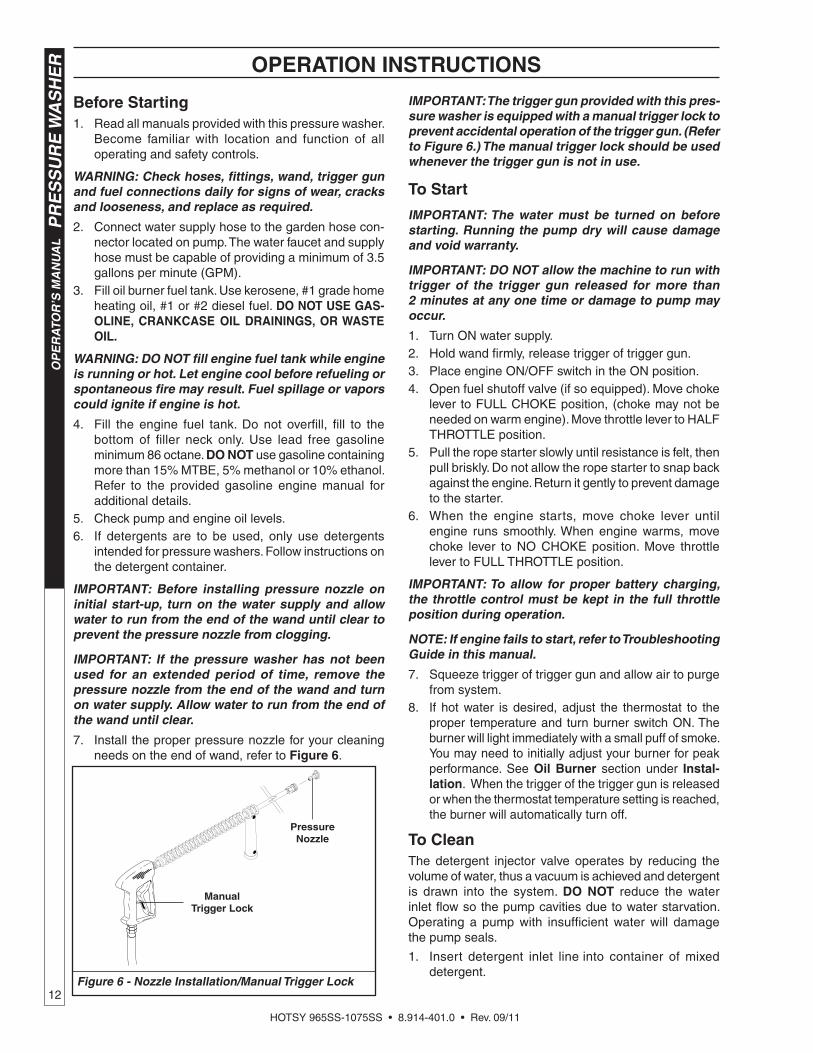
7. Install the proper pres sure nozzle for your cleaning needs on the end of wand, refer to Figure 6.
IMPORTANT: The trigger gun pro vid ed with this pres -sure washer is equipped with a manual trig ger lock to prevent accidental op er a tion of the trigger gun. (Refer to Figure 6.) The manual trigger lock should be used whenever the trig ger gun is not in use.
To Start
IMPORTANT: The water must be turned on before start ing. Run ning the pump dry will cause damage and void warranty.
IMPORTANT: DO NOT allow the ma chine to run with trig ger of the trig ger gun re leased for more than 2 minutes at any one time or damage to pump may oc cur.
1. Turn ON water supply.2. Hold wand fi rmly, release trigger of trigger gun.3. Place engine ON/OFF switch in the ON position.4. Open fuel shutoff valve (if so equipped). Move choke
le ver to FULL CHOKE position, (choke may not be need ed on warm engine). Move throttle lever to HALF THROTTLE position.
5. Pull the rope starter slowly until resistance is felt, then pull briskly. Do not allow the rope starter to snap back against the engine. Return it gently to prevent dam age to the starter.
6. When the engine starts, move choke lever until engine runs smoothly. When engine warms, move choke lever to NO CHOKE position. Move throttle lever to FULL THROT TLE position.
IMPORTANT: To allow for proper battery charging, the throttle control must be kept in the full throttle po si tion during operation.
NOTE: If engine fails to start, refer to Trou ble shoot ing Guide in this manual.
7. Squeeze trigger of trigger gun and allow air to purge from system.
8. If hot water is de sired, adjust the thermostat to the prop er temperature and turn burner switch ON. The burner will light im me di ate ly with a small puff of smoke. You may need to initially adjust your burner for peak per for mance. See Oil Burner section under In stal -la tion. When the trigger of the trig ger gun is released or when the thermostat tem per a ture set ting is reached, the burn er will au to mat i cal ly turn off.
To CleanThe detergent injector valve operates by reducing the vol ume of water, thus a vacuum is achieved and detergent is drawn into the system. DO NOT reduce the water inlet fl ow so the pump cavities due to water starvation. Operating a pump with insuffi cient water will damage the pump seals.
1. Insert detergent inlet line into container of mixed detergent.
Figure 6 - Nozzle Installation/Manual Trigger Lock
ManualTrigger Lock
PressureNozzle
HOTSY 965SS-1075SS • 8.914-401.0 • Rev. 09/11
13
PR
ES
SU
RE
WA
SH
ER
OP
ER
ATO
R’S
MA
N U
AL
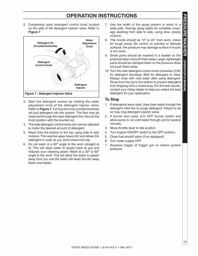
2. Completely open de ter gent con trol knob located on the side of the de ter gent injector valve. Refer to Figure 7.
3. Start the de ter gent suction by ro tat ing the water adjustment knob of the detergent in jec tor valve. Refer to Fig ure 7. Turning the knob coun ter clock wise will pull de ter gent into the system. The fl ow may be ob served through the clear de ter gent line. Secure the knob po si tion with the knurled nut.
4. The side detergent control knob can now be ad just ed to meter the desired amount of detergent.
5. Wash from the bottom to the top, using side to side motions. This washes away heavy dirt and allows the detergent to soak as you work to ward the top.
6. Do not wash at a 90o angle to the work (straight at it). This will allow water to splash back at you and reduces your cleaning power. Wash at a 30o to 60o an gle to the work. This will allow the water to splash away from you and the water will wash the dirt away faster and eas i er.
7. Use the width of the spray pattern to wash in a wide path. Overlap spray paths for complete cover-age wash ing from side to side, using slow, steady motions.
8. The nozzle should be 12" to 24" from work, closer for tough areas. Be careful on painted or del i cate sur fac es, the pressure may damage surface if noz zle is too close.
9. Small parts should be washed in a basket so the pres sure does not push them away. Larg er, light weight parts should be clamped down so the pres sure does not push them away.
10. Turn the side de ter gent control knob clockwise (CW) for detergent decrease. Wait for de ter gent to clear. Always rinse with cold water after using de ter gent. Rinse from the top to the bottom to pre vent de ter gent from dripping onto a rinsed area. For the best re sults, con tact your Hotsy dealer to help you select the best de ter gent for your application.
To Stop1. If detergents were used, draw clear water through the
detergent inlet line to purge detergent. Failure to do so may clog detergent injector valve.
2. If burner was used, turn OFF burner switch and allow pump to run cold water through coil for several min utes.
3. Move throttle lever to idle position.4. Turn engine ON/OFF switch to the OFF position.5. Close fuel shutoff valve (if so equipped).6. Turn water supply OFF.7. Squeeze trigger of trig ger gun to relieve sys tem
pressure.
OPERATION INSTRUCTIONS
Figure 7 - Detergent Injector Valve
WaterAdjustment
KnobDetergent On
(Counterclockwise)
Detergent Control Knob
Detergent Injector
HOTSY 965SS-1075SS • 8.914-401.0 • Rev. 09/11
OP
ER
ATO
R’S
MA
NU
AL
P
RE
SS
UR
E W
AS
HE
R
14
Pre-rinse clean ing surface with fresh water. Place de ter -gent suc tion tube di rect ly into clean ing so lu tion and ap ply to sur face at low pressure (for best re sults, limit your work area to sections ap prox i mate ly 6 feet square and al ways ap ply de ter gent from bottom to top). Allow de ter gent to re main on sur face 1-3 min utes. Do not al low de ter gent to dry on sur face. If sur face appears to be drying, sim ply wet down sur face with fresh water. If need ed, use brush to re move stub born dirt. Rinse at high pres sure from top to bottom in an even sweeping mo tion keep ing the spray nozzle ap prox i mate ly 1 foot from cleaning sur face. Use over lap ping strokes as you clean and rinse any sur face. For best surface clean ing action spray at a slight an gle.
Recommendations: • Before cleaning any surface, an inconspicuous
area should be cleaned to test spray pattern and dis tance for maximum cleaning results.
• If painted surfaces are peeling or chipping, use ex treme caution as pressure washer may re move the loose paint from the surface.
• Keep the spray nozzle a safe distance from the sur face you plan to clean. High pressure wash a small area, then check the surface for damage. If no dam age is found, continue to pressure wash ing.
CAUTION - Never use: • Bleach, chlorine products and other corrosive
chem i cals • Liquids containing solvents (i.e., paint thinner,
gas o line, oils) • Tri-sodium phosphate products • Ammonia products • Acid-based productsThese chemicals will harm the machine and will dam age the surface being cleaned.
RINSING
It will take a few sec onds for the de ter gent to clear. Apply safe ty latch to spray gun. Select and in stall de- sired high pres sure noz zle. NOTE: You can also stop de ter gent from fl ow ing by removing de ter gent si phon tube from bottle.
STORAGEDANGER: DO NOT store fl am ma ble liquids (gas o line, die sel fuel, sol vents, etc.) near pressure wash er, or in non-ven ti lat ed ar eas.
Protect from freezing by storing in a heated area, or by fl ush ing the system with antifreeze (use an au to mo tive engine antifreeze or windshield washer sol vent to an ti freeze). To flush the system with an ti freeze, the following steps are to be followed:
1. Connect water supply hose to the garden hose con-nector located on the pump. Turn on water sup ply.
2. Place the detergent inlet line into a container of
GENERAL CLEANING TECHNIQUES & STORAGE
antifreeze.3. Hold wand fi rmly, release trigger of trigger gun.4. Start engine. Place throttle lever in Full Throttle
po si tion.5. Squeeze trig ger of trig ger gun and al low wa ter to
fl ow from the end of the wand. Watch for antifreeze to be drawn through the detergent inlet line. Allow the an ti freeze to be drawn into the system for 5 to 10 sec onds.
6. Release the trigger of the trigger gun and stop engine.
7. Turn off water supply and disconnect water supply hose from the pump.
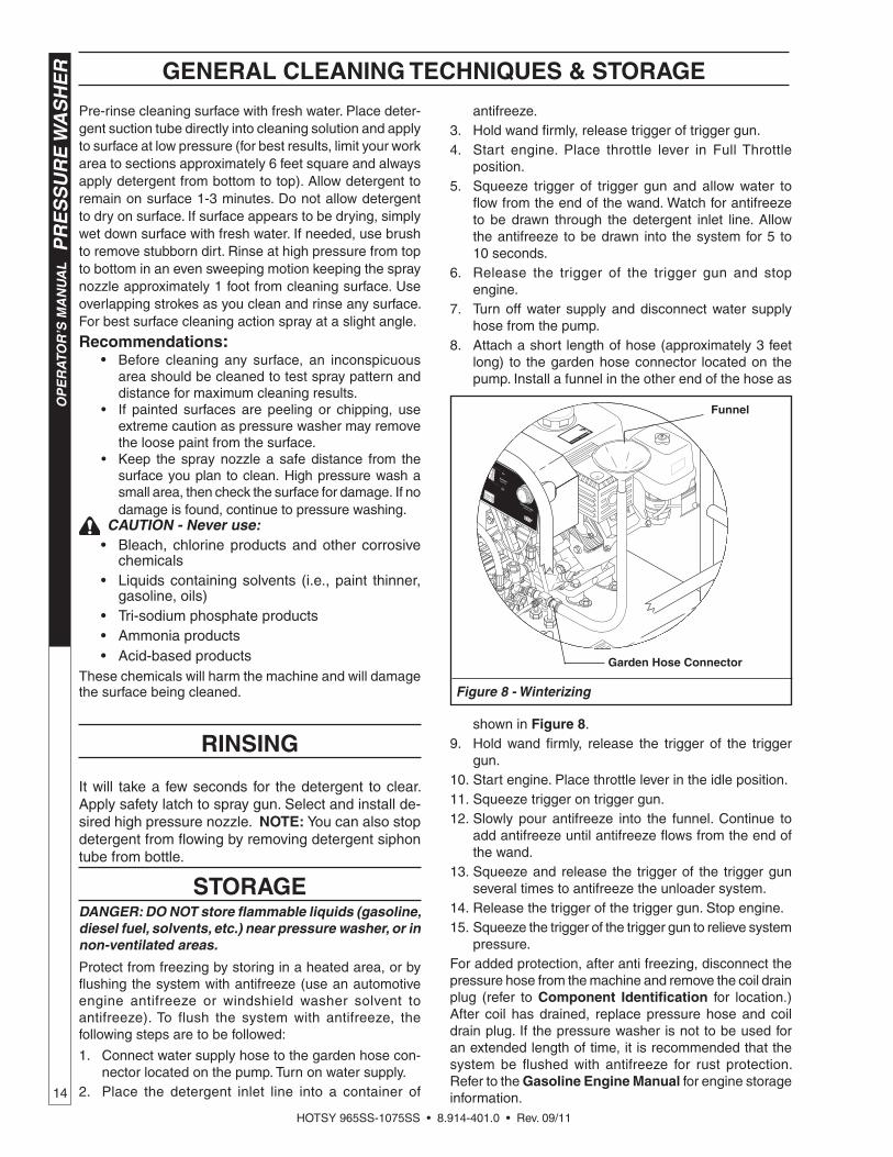
8. Attach a short length of hose (approximately 3 feet long) to the garden hose connector located on the pump. Install a funnel in the other end of the hose as
shown in Figure 8.9. Hold wand fi rmly, release the trigger of the trigger
gun.10. Start engine. Place throttle lever in the idle position.11. Squeeze trigger on trigger gun.12. Slowly pour antifreeze into the funnel. Continue to
add antifreeze until antifreeze fl ows from the end of the wand.
13. Squeeze and re lease the trigger of the trigger gun several times to antifreeze the unloader sys tem.
14. Release the trigger of the trigger gun. Stop engine.15. Squeeze the trigger of the trigger gun to relieve sys tem
pressure.For added protection, after anti freezing, disconnect the pres sure hose from the machine and remove the coil drain plug (refer to Component Identifi cation for location.) After coil has drained, re place pressure hose and coil drain plug. If the pressure wash er is not to be used for an extended length of time, it is recommended that the system be fl ushed with an ti freeze for rust protection. Refer to the Gasoline Engine Manual for engine stor age information.
CHAUD!
Funnel
Garden Hose Connector
Figure 8 - Winterizing

HOTSY 965SS-1075SS • 8.914-401.0 • Rev. 09/11
15
PR
ES
SU
RE
WA
SH
ER
OP
ER
ATO
R’S
MA
N U
AL
MAINTENANCE
WARNING: Unauthorized machine modifi cation or use of non-approved replacement parts may cause per son al injury and/or property damage and will void the manufacturer warranty.
PumpLubrication: To lubricate pump, use 30W (non-detergent) oil for pump crankcase. Crankcase must be fi lled to center of red dot on oil gauge found on the side of the pump, refer to Figure 9. During the break-in-period, make sure the oil is changed after the fi rst 40 hours of operation. After that, re place oil every 3 months or 500 hours of operation, which ev er comes fi rst.
Proper Pump Care:• DO NOT pump acids.
• DO NOT allow pump to run dry.
• Winterize if storing in freezing temperatures, refer to Stor age for details.
• Use a water softener on the water system if known to be high in mineral content.
• Use only high quality detergents and follow man u -fac tur er's mix recommendations.
• Flush the system with clear water immediately after using detergent solutions.
• Clean fi lter screen on detergent inlet l ine periodically.
• Flush the pressure washer system with antifreeze if stor ing for an extended period of time, refer to Storage for details.
Gasoline EngineRefer to the provided Gasoline Engine Manual for rec om mend ed maintenance.
Oil BurnerBlower Motor: Inspect the motor brushes for wear every 250 hours of operation and replace when 1/8" to 1/4" brush material remains. DO NOT allow the brushes to wear out completely or motor damage will occur. Refer to Burner Assembly. The motor bearings are permanently lubricated and will not require any additional lubrication.
Unloader Valve/ Relief valve
WARN ING: The unloader valve and relief valve on this pressure wash er has been fac to ry set and sealed and is a fi eld non ad just able part. Tam per ing with the facto-ry set ting may cause personal in ju ry and/or prop er ty dam age, and will void the manufacturer war ran ty. For replacement refer to Pump Assembly.
Burner Fuel FilterDrain any water which has accumulated in fuel fi lter and clean or replace fi lter element as needed. Refer to Burner Assembly.
Heating CoilCoil Descaling: In hard water areas, scale buildup within the heating coil will occur. Scale deposits will decrease the water temperature rise and may eventually clog the heat ing coil. Contact your local service center when descaling is needed.
Coil Desooting: Poor grades of fuel oil or in ad e quate com bus tion air will cause heavy soot buildup on the outside surface of the heating coil. These deposits will insulate the coil. This will restrict the air fl ow through the coil, further aggravating the soot buildup. Contact your local service center when desooting is needed.
Hour MeterThis hour meter will monitor the total hours of operation of the pressure washer to sig nal when routine main te nance is required.
BatteryRefer to battery manufacturer’s literature for recommended maintenance.
Relief Valve
WARNING: The relief valve on this pressure washer has been factory set and sealed and is a fi eld non-adjustable part. Tampering with the factory setting may cause personal injury and/or property damage, and will void the manufacturer warranty. For replace-
ment parts refer to Coil Outlet Assembly.
If pressure from pump or thermal expansion should exceed safe limits, the relief valve will open, allowing high pressure to be discharged through hose to ground. Caution: Inspect relief valve annually for any obstruction.
Oil Fill/Dipstick
Oil Drain Plug
Oil Sight Glass
Figure 9 - Pump Lubrication

HOTSY 965SS-1075SS • 8.914-401.0 • Rev. 09/11
PR
ES
SU
RE
WA
SH
ER
Tr
ou
bles
ho
oti
ng
Gu
ide
16
TROUBLESHOOTING
SYMPTOM POSSIBLE CAUSES CORRECTIVE ACTION
GAS ENGINE WILLNOT RUN.
Out of gas Replenish supply. Use only recommended fuels. Refer to Before Starting under Operation.
Fuel valve closed (if so equipped) Open valve.
Loose spark plug wire Reconnect.
Choke or throttle set incorrectly Refer to To Start under Operation.
Engine ON/OFF switch in OFF position
Place engine ON/OFF switch in ON posi-tion.
Low engine oil level Replenish supply. Engine will not start or run if oil is low (on engines equipped with low oil protection).
Refer to provided gasoline engine manual for additional troubleshooting.
PRESSURE WASHER RUNS BUT WON’T SPRAY.
Trigger of trigger gun released Squeeze trigger.
Water supply not turned on Open water supply valve.
Clogged pressure nozzle Clean pressure nozzle opening.
If water spray doesn’t show with in 10-15 seconds
Discontinue running the machine and troubleshoot as damage to the pump will occur if allowed to run.
LOW SPRAY PRESSURE AT PRESSURE NOZZLE.
Inadequate water supply Fully open faucet. Check for kinked or dam-aged hose. Use 3/4 inch minimum hose. Check for debris clogging inlet screen.
Partially clogged or damaged pres-sure nozzle
Clean or replace.
Air being drawn through detergent inlet line
Refi ll detergent container. Ensure that pick-up screen is fully immersed.
Detergent injector valve not set correctly
Refer to To Clean for settings.
UNEVEN SPRAY PATTERN.
Partially clogged or damaged pres-sure nozzle
Clean or replace.
PRESSURE WASHER WILL NOT PRODUCE HOT WATER.
Burner switch in OFF position Place switch in ON position.
Inadequate fuel supply Refi ll fuel tank. Use only recommended fuels. Refer to Before Starting under Op-eration.
Inadequate water supply Fully open faucet. Check for kinked or dam-aged hose. Use 3/4 inch minimum hose. Check for debris clogging inlet screen.
Trigger of trigger gun released Squeeze trigger. Water must be spraying for burner to light.
Thermostat set too low Adjust thermostat to desired temperature.
Blown fuse Replace. Fuse is located in control box.
Engine is running too slow Move throttle lever to full throttle position.

HOTSY 965SS-1075SS • 8.914-401.0 • Rev. 09/11
17
PR
ES
SU
RE
WA
SH
ER
Trou
blesho
otin
g G
uid
eTROUBLESHOOTING
When ordering from your dealer, please provide the following:
Model Number: 965SS, 1060SS, 1065SS, 1065SSE, 1075SSE
Machine Serial Number: ________________________________
Component Part Number: ______________________________
Description: __________________________________________
IMPORTANTIf the pressure washer demonstrates other symptoms or the corrective actions list ed do not correct the problem, contact the local authorized Hotsy Service Center. The Hotsy Service Center can be identifi ed by visiting www.hotsy.com.
SYMPTOM POSSIBLE CAUSES CORRECTIVE ACTION
POOR OR NO DETERGENT FLOW.
Inadequate detergent supply. Refill detergent container. Ensure that pick-up screen is fully immersed. Open detergent valve.
Detergent screen or hose clogged. Clean. Always start with a clean detergent container.
Detergent injector valve not set correctly.
Refer to To Clean for settings.
Clogged detergent injector check valve.
Clean check valve at detergent injector inlet
POOR CLEANING. Improper detergent concentration or mixing.
Mix detergent per manufacturer’s instruc-tions. Ensure that powdered detergents are fully dissolved.
Wrong detergent for the application. Select appropriate detergent.
Rinsing with hot water. A fi nal rinse with cold water will reduce water spotting.
HOTSY 965SS-1075SS • 8.914-401.0 • Rev. 09/11
35
PR
ES
SU
RE
WA
SH
ER
WA
RR
AN
TY
HOTSY LIMITED NEW PRODUCT WARRANTYPRESSURE WASHERS
WHAT THIS WARRANTY COVERSAll Hotsy pressure washers are warranted by Hotsy to the original purchaser to be free from defects in materials and work-manship under normal use, for the periods specified below. This Limited Warranty is subject to the exclusions shown below, is calculated from the date of the original purchase, and applies to the original components only. Any parts replaced under this warranty will assume the remainder of the part’s warranty period.
SEVEN YEAR PARTS AND ONE YEAR LABOR WARRANTY:Components manufactured by Hotsy, such as frames, handles, top and bottom wraps, float tanks, fuel tanks, belt guards, andinternal components on the oil-end of HOTSY manufactured pumps. General, AR, Liberty, Comet and swash and wobble plate pumps have a one year warranty. Heating coils have a five year warranty from date of original machine purchase.
ONE YEAR PARTS AND ONE YEAR LABOR WARRANTY:All other components, excluding normal wear items as described below, will be warranted for one year on parts and labor. Parts and labor warranty on these parts will be for one year regardless of the duration of the original component manufacturer’s part warranty.
WARRANTY PROVIDED BY OTHER MANUFACTURERS:Motors, generators, and engines, which are warranted by their respective manufacturers, are serviced through these manu-facturers’ local authorized service centers. Hotsy is not authorized and has no responsibility to provide warranty service for such components.
WHAT THIS WARRANTY DOES NOT COVERThis warranty does not cover the following items:
1. Normal wear items, such as nozzles, spray guns, discharge hoses, wands, quick couplers, seals, filters, gaskets, O-rings, packings, pistons, pump valve assemblies, strainers, belts, brushes, relief valves, fuses, pump protec -tors.
2. Damage or malfunctions resulting from accidents, abuse, modifications, alterations, incorrect installation, improper servicing, failure to follow manufacturer’s maintenance instructions, or use of the equipment beyond its stated us-age specifications as contained in the operator’s manual.
3. Damage due to freezing, chemical deterioration, scale build up, rust, corrosion, or thermal expansion.4. Damage to components from fluctuations in electrical or water supply.5. Normal maintenance service, including adjustments, fuel system cleaning, and clearing of obstructions.6. Transportation to service center, field labor charges, or freight damage.
WHAT YOU MUST DO TO OBTAIN WARRANTY SERVICEIn order to obtain warranty service on items warranted by Hotsy, you must return the product to your Authorized Hotsy Distributor, freight prepaid, with proof of purchase, within the applicable warranty period. If the product is permanently installed, you must notify your Authorized Hotsy Distributor of the defect. Your Authorized Hotsy Distributor will file a claim with Hotsy, who must subsequently verify the defect. In most cases, the part must be returned to Hotsy freight prepaid with the claim. For warranty service on components warranted by other manufacturer’s, your Authorized Hotsy Distributor can help you obtain warranty service through these manufacturers’ local authorized service centers.
LIMITATION OF LIABILITYHotsy’s liability for special, incidental, or consequential damages is expressly disclaimed. In no event shall Hotsy’s liability exceed the purchase price of the product in question. Hotsy makes every effort to ensure that all illustrations and specifica-tions are correct, however, these do not imply a warranty that the product is merchantable or fit for a particular purpose, or that the product will actually conform to the illustrations and specifications. Our obligation under this warranty is expressly limited at our option to the replacement or repair at a service facility or factory designated by us, of such part or parts as inspection shall disclose to have neen defective. THE WARRANTY CONTAINED HEREIN IS IN LIEU OF ALL OTHER WARRANTIES, EXPRESS OR IMPLIED, INCLUDING ANY IMPLIED WARRANTY OF MERCANTABILITY OR FITNESS FOR A PARTICULAR PURPOSE ARE EXPRESSLY LIMITED TO THE DURATION OF THIS WRITTEN WARRANTY. Hotsy does not authorize any other party, including authorized Hotsy Distributors, to make any representation or promise on behalf of Hotsy, or to modify the terms, conditions, or limitations in any way. It is the buyer’s responsibility to ensure that the installation and use of Hotsy products conforms to local codes. While Hotsy attempts to assure that its products meet national codes, it cannot be responsible for how the customer chooses to use or install the product. Some states do not al-low limitations on how long an implied warranty lasts or the exclusion or limitation of incidental or consequential damages, so the above limitation or exclusion may not apply to you. This warranty gives you specific legal rights and you may also have other rights which vary from state to state.
HOTSYwww.hotsy.com

If you are looking for replacement parts for your Hotsy, please contact your local dealer. You can find a dealer by calling Hotsy at 800-525-1976 or by visiting www.hotsy.com.
Form #8.914-401.0 • 965SS-1075SS • Revised 09/11 • Printed in U.S.A.
If you need service on your pressure washer, contact your local Hotsydealer or visit www.Hotsy.com. Smart phone users scan the code below to
link directly to the Service Request page.


![Nilfisk-Advance [2014/July]/Pressure Washers/Consumer ... · Nilfisk-Advance [2014/July]/Pressure Washers/Consumer Pressure Washers/Pro/AQUA 700 & 800/AQUA 700/Frame AQUA 700 28.07.2015](https://img.pdfslide.us/doc/110x75/60cadcf39a3a4349a647a9df/nilfisk-advance-2014julypressure-washersconsumer-nilfisk-advance-2014julypressure.jpg)