Embed Size (px)
Citation preview
Th is manual must only be used by a qualifi ed heating installer/service technician. Read all instructions, including this manual and all other information shipped with the boiler, before installing. Perform steps in the order given. Failure to comply could result in severe personal injury, death or substantial property damage.DO NOT operate the boiler during construction unless combustion air is piped to the boiler air inlet from a dust-free and contaminant-free area. Th e boiler can be severely damaged by drywall dust or other combustion air contaminants.
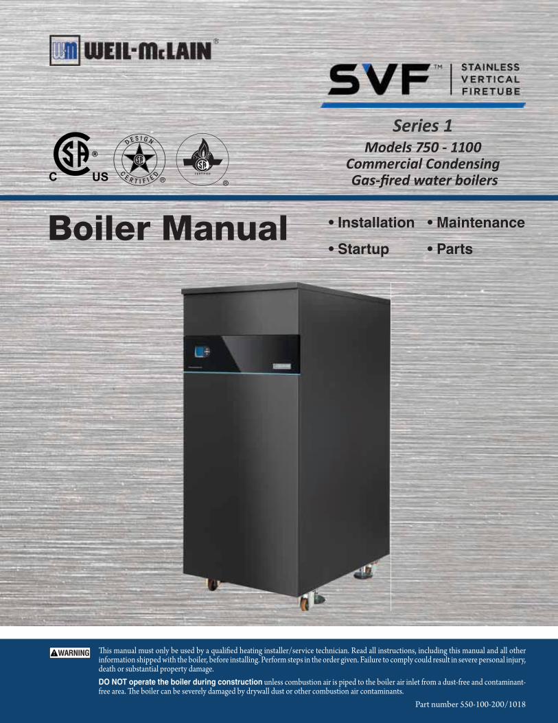
• Installation
• Startup
• Maintenance
• PartsBoiler Manual
Part number 550-100-200/1018
Series 1Models 750 - 1100
Commercial Condensing�������������� �����
The SVFTM Commercial Condensing Water Boiler
SVF ™ Series 1 COMMERCIAL CONDENSING GAS-FIRED WATER BOILER — Boiler Manual
Part number 550-100-200/10182
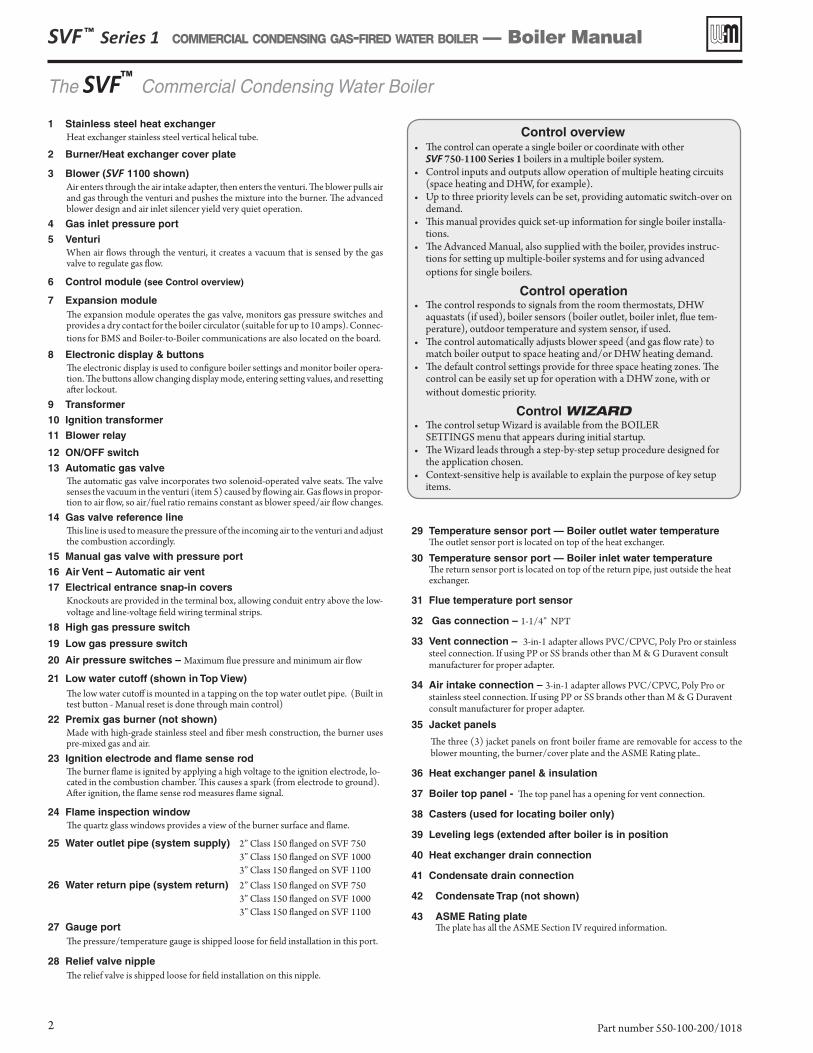
1 Stainless steel heat exchangerHeat exchanger stainless steel vertical helical tube.
2 Burner/Heat exchanger cover plate
3 Blower (SVF 1100 shown)Air enters through the air intake adapter, then enters the venturi. The blower pulls air and gas through the venturi and pushes the mixture into the burner. The advanced blower design and air inlet silencer yield very quiet operation.
4 Gas inlet pressure port
5 VenturiWhen air flows through the venturi, it creates a vacuum that is sensed by the gas valve to regulate gas flow.
6 Control module (see Control overview)
7 Expansion moduleThe expansion module operates the gas valve, monitors gas pressure switches and provides a dry contact for the boiler circulator (suitable for up to 10 amps). Connec-tions for BMS and Boiler-to-Boiler communications are also located on the board.
8 Electronic display & buttonsThe electronic display is used to configure boiler settings and monitor boiler opera-tion. The buttons allow changing display mode, entering setting values, and resetting after lockout.
9 Transformer
10 Ignition transformer
11 Blower relay
12 ON/OFF switch
13 Automatic gas valveThe automatic gas valve incorporates two solenoid-operated valve seats. The valve senses the vacuum in the venturi (item 5) caused by flowing air. Gas flows in propor-tion to air flow, so air/fuel ratio remains constant as blower speed/air flow changes.
14 Gas valve reference lineThis line is used to measure the pressure of the incoming air to the venturi and adjust the combustion accordingly.
15 Manual gas valve with pressure port
16 Air Vent – Automatic air vent
17 Electrical entrance snap-in coversKnockouts are provided in the terminal box, allowing conduit entry above the low-voltage and line-voltage field wiring terminal strips.
18 High gas pressure switch
19 Low gas pressure switch
20 Air pressure switches – Maximum flue pressure and minimum air flow
21 Low water cutoff (shown in Top View)The low water cutoff is mounted in a tapping on the top water outlet pipe. (Built in test button - Manual reset is done through main control)
22 Premix gas burner (not shown)Made with high-grade stainless steel and fiber mesh construction, the burner uses pre-mixed gas and air.
23 Ignition electrode and flame sense rodThe burner flame is ignited by applying a high voltage to the ignition electrode, lo-cated in the combustion chamber. This causes a spark (from electrode to ground). After ignition, the flame sense rod measures flame signal.
24 Flame inspection windowThe quartz glass windows provides a view of the burner surface and flame.
25 Water outlet pipe (system supply) 2” Class 150 flanged on SVF 750 3” Class 150 flanged on SVF 1000 3” Class 150 flanged on SVF 1100
26 Water return pipe (system return) 2” Class 150 flanged on SVF 750 3” Class 150 flanged on SVF 1000 3” Class 150 flanged on SVF 1100
27 Gauge portThe pressure/temperature gauge is shipped loose for field installation in this port.
28 Relief valve nippleThe relief valve is shipped loose for field installation on this nipple.
Control overview• The control can operate a single boiler or coordinate with other
SVF 750-1100 Series 1 boilers in a multiple boiler system. • Control inputs and outputs allow operation of multiple heating circuits
(space heating and DHW, for example). • Up to three priority levels can be set, providing automatic switch-over on
demand.• This manual provides quick set-up information for single boiler installa-
tions.• The Advanced Manual, also supplied with the boiler, provides instruc-
tions for setting up multiple-boiler systems and for using advanced options for single boilers.
Control operation• The control responds to signals from the room thermostats, DHW
aquastats (if used), boiler sensors (boiler outlet, boiler inlet, flue tem-perature), outdoor temperature and system sensor, if used.
• The control automatically adjusts blower speed (and gas flow rate) to match boiler output to space heating and/or DHW heating demand.
• The default control settings provide for three space heating zones. The control can be easily set up for operation with a DHW zone, with or without domestic priority.
Control WIZARD• The control setup Wizard is available from the BOILER
SETTINGS menu that appears during initial startup.• The Wizard leads through a step-by-step setup procedure designed for
the application chosen.• Context-sensitive help is available to explain the purpose of key setup
items.
29 Temperature sensor port — Boiler outlet water temperature The outlet sensor port is located on top of the heat exchanger.
30 Temperature sensor port — Boiler inlet water temperature The return sensor port is located on top of the return pipe, just outside the heat exchanger.
31 Flue temperature port sensor
32 Gas connection – 1-1/4” NPT
33 Vent connection – 3-in-1 adapter allows PVC/CPVC, Poly Pro or stainless steel connection. If using PP or SS brands other than M & G Duravent consult manufacturer for proper adapter.
34 Air intake connection – 3-in-1 adapter allows PVC/CPVC, Poly Pro or stainless steel connection. If using PP or SS brands other than M & G Duravent consult manufacturer for proper adapter.
35 Jacket panels
The three (3) jacket panels on front boiler frame are removable for access to the blower mounting, the burner/cover plate and the ASME Rating plate..
36 Heat exchanger panel & insulation
37 Boiler top panel - The top panel has a opening for vent connection.
38 Casters (used for locating boiler only)
39 Leveling legs (extended after boiler is in position
40 Heat exchanger drain connection
41 Condensate drain connection
42 Condensate Trap (not shown)
43 ASME Rating plate The plate has all the ASME Section IV required information.
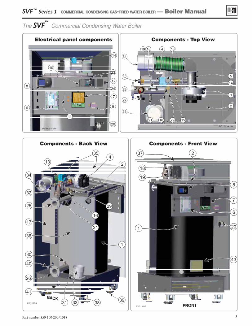
Electrical panel components
SVF-1100-Fr Elec
11
20
9
7
24
23
14
8
6
10
12
Components - Top View
SVF-1100 top view
15
2
2916
33
27
28
32
34
1819 4 13
3
14
5
21
SVF-1100-F FRONT
37 2
1 20
6
7
18
819
43
Components - Front ViewComponents - Back View
BACKSVF-1100-B
39
36
41
40
33
26
30
17
2925
32
34
13
35
1
24
38
21
16
31
SVF ™ Series 1 COMMERCIAL CONDENSING GAS-FIRED WATER BOILER — Boiler Manual
Part number 550-100-200/1018 3
The SVFTM
Commercial Condensing Water Boiler
Contents . . . . . . . . . . . . . . . . . . . 4
Hazard definitions . . . . . . . . . . . . . . . 4
Please read before proceeding . . . . . . . . . . 5
Prepare boiler location . . . . . . . . . . . . . 6
Prepare boiler . . . . . . . . . . . . . . . . . 9
Propane conversion procedure . . . . . . . . . 12
Install water piping . . . . . . . . . . . . . . 14
Venting/air piping — Massachusetts installations . 22
Venting/combustion air — general . . . . . . . 23
Venting/combustion air — options (Category II & IV) 25
Appliances remaining on an existing vent system . 26
Venting/combustion air — options (Category II) . . 27
DIRECT EXHAUST — Boiler room air openings (Category II and IV) 30
DIRECT EXHAUST — Sidewall Termination location (Category IV) 33
DIRECT EXHAUST — Sidewall (Category IV) . . . 34
DIRECT EXHAUST — Vertical (Category II and IV) . 32
DIRECT VENT — Boiler room air openings (Category IV) . 36
DIRECT VENT — Sidewall Termination location (Category IV) . .38
DIRECT VENT — Sidewall (Category IV) . . . . . 39
DIRECT VENT — Vertical (Category IV) . . . . . . 41
Install condensate components. . . . . . . . . 44
Gas piping . . . . . . . . . . . . . . . . . 45
Gas Train Diagram . . . . . . . . . . . . . . 46
Field wiring (see Figure 57 & Figure 58) . . . . . 47
Zoning with the SVFTM Control . . . . . . . . . 60
Control operation and setup . . . . . . . . . . 62
CONTRACTOR menus. . . . . . . . . . . . . 68
BOILER SETTINGS menu, BASIC mode . . . . . 69
PRIORITY 1, 2, 3 menus, BASIC mode . . . . . . 70
ASSIGN INPUTS menu, BASIC mode . . . . . . 71
DIAGNOSTIC menu . . . . . . . . . . . . . . 73
MAINTENANCE, DATE AND TIME menus . . . . . 78
Startup — fill the system . . . . . . . . . . . 79
Startup — final checks . . . . . . . . . . . . 81
Startup procedure . . . . . . . . . . . . . . 82
Annual startup and maintenance schedule . . . . 86
Annual startup . . . . . . . . . . . . . . . . 87
Troubleshooting . . . . . . . . . . . . . . . 93
Maintenance. . . . . . . . . . . . . . . . . 102
Replacement parts . . . . . . . . . . . . . . 105
Dimensions . . . . . . . . . . . . . . . . . 112
atings — SVFTM Series 1 boilers . . . . . . . . . 114
Installation and Service Certificate . . . . . . . 115
Installation and Gas Boiler Data Collection Sheet . 117
Notes. . . . . . . . . . . . . . . . . . . . 118
Contents
The following defined terms are used throughout this manual to bring attention to the presence of hazards of various risk levels or to important information concerning the life of the product.
Indicates presence of hazards that will cause severe personal injury, death or substantial property damage.
Indicates presence of hazards that can cause severe personal injury, death or substantial property damage.
Indicates presence of hazards that will or can cause minor personal injury or property damage.
Indicates special instructions on installation, operation or maintenance that are important but not related to personal injury or property damage.
Hazard definitions
DO NOT START THIS BOILER without following all instructions and procedures specified in the following sections: "Startup — fill the system" on page 79 "Startup — final checks" on page 81 "Startup procedure" on page 82.
Failure to follow the instructions in this manual could result in severe personal injury, death or substantial property dam-age.
SVF ™ Series 1 COMMERCIAL CONDENSING GAS-FIRED WATER BOILER — Boiler Manual
Part number 550-100-200/10184
Please read before proceeding
SVF ™ Series 1 COMMERCIAL CONDENSING GAS-FIRED WATER BOILER — Boiler Manual
Part number 550-100-200/1018 5
Failure to adhere to the guidelines below can result in severe personal injury, death or substantial property damage.
When servicing boiler —
• To avoid electric shock, disconnect all electrical supplies to the boiler before performing maintenance.
• To avoid severe burns, allow boiler to cool before performing maintenance.
• This boiler contains ceramic fiber and fiberglass materials. Refer to the WARN-ING and instructions on page 87.
Boiler operation —• Do not block flow of combustion or
ventilation air to boiler.
• Should overheating occur or gas supply fail to shut off, do not turn off or discon-nect electrical supply to pump. Instead, shut off the gas supply at a location external to the appliance.
Boiler water —
• The heat exchanger is made of stain-less steel, and requires that system pH always be between 7.0 and 8.5 and water chemistr y be checked.
Chemical treatment is required. See pages 79 and 80 for details.
• Thoroughly flush the system (with-out boiler connected) to remove sedi-ment. Install a strainer or other sedi-ment removal equipment if necessary. The high-efficiency heat exchanger can be damaged by build-up or corrosion due to sediment.
• Do not use petroleum-based cleaning or sealing compounds in boiler system. Gaskets and seals in the system may be damaged. This can result in substantial property damage.
• Continual fresh make-up water will re-duce boiler life. Mineral buildup in heat exchanger reduces heat transfer, over-heats the stainless steel heat exchanger, and causes failure. Addition of oxygen carried in by make-up water can cause internal corrosion. Leaks in boiler or pip-ing must be repaired at once to prevent make-up water. Use this boiler ONLY in a closed-loop system.
• Do not add cold water to a hot boiler. Thermal shock can cause heat exchanger to crack.
Freeze protection fluids —
NEVER use automotive or standard glycol antifreeze, even glycol made for hydronic systems. Use only freeze-protection fluids recommended in this manual (see page 79). Follow all guidelines given. Thoroughly clean and flush any replacement boiler sys-tem that has used glycol before installing the new SVFTM boiler.
Frozen Water Damage Hazard
Residences or buildings that are unattended in severely cold weather, boiler system components failures, power outages, or other electrical system failures could result in frozen plumbing and water damage in a matter of hours. For your protection, take preventative actions such as having a security system installed that operates during power outages, senses low temperature, and initi-ates an effective action. Consult with your boiler contractor or a home security agency.
If any part of a boiler, burner or its controls has been sprayed with or submerged under water, either partially or fully, DO NOT attempt to op-erate the boiler until the boiler has been either replaced or completely repaired, inspected, and you are sure that the boiler and all compo-nents are in good condition and fully reliable. Otherwise, by operating this boiler, you will cause a fire or explosion hazard, and an electrical shock hazard, leading to serious injury, death, or substantial property damage. See the instructions at right.
Saltwater Damage — The exposure of boiler components to saltwater can have both immediate and long-term effects. While the immediate effects of saltwater damage are similar to those of fresh-water (shorting out of electrical components, washing out of critical lubricants, etc.), salt and other contaminants left behind can lead to longer term issues after the water is gone due to the conductive and corrosive nature of the salt residue. Therefore, Weil-McLain equip-ment contaminated with saltwater or polluted water will no longer be covered under warranty and should be replaced.
Electrical Damage — If any electrical component or wiring came into contact with water, or was suspected to have come into contact with water, replace the boiler with a new Weil-McLain boiler.
Installer— Read all instructions, including this manual and all other information shipped with the boiler, before installing. Perform steps in the order given.
User — This manual is for use only by a qualified heating installer/service technician. Refer to User’s Information Manual for your reference.
User — Have this boiler serviced/inspected by a qualified service technician, at least annually.
Failure to comply with the above could result in severe personal injury, death or substantial property damage.
Write in the CP number in the space provided on the Installation certificate on page 115 if not already shown.
When calling or writing about the boiler— Please have the boiler model number from the boiler rating label and the CP number from the boiler jacket.
Consider piping and installation when determining boiler location.
Any claims for damage or shortage in shipment must be filed immediately against the transportation com-pany by the consignee.
Commonwealth of Massachusetts
When the boiler is installed within the Commonwealth of Massachusetts:• This product must be installed by a licensed plumber or gas fitter.• If antifreeze is used, a reduced pressure back-flow preventer device shall be used.• Sidewall vent air installations — see instruction on page 22.
Prepare boiler location
SVF ™ Series 1 COMMERCIAL CONDENSING GAS-FIRED WATER BOILER — Boiler Manual
Part number 550-100-200/10186
Installations must comply with:• Local, state, provincial, and national codes, laws, regulations and
ordinances.• National Fuel Gas Code, ANSI Z223.1/NFPA 54 - latest edition.• National Electrical Code ANSI/NFPA 70 – latest edition.
Electrical installation and grounding must be in accordance with CSA C22.1, Part 1, Canadian Electrical Code, and/or local codes.
• For Canada only: CAN/CSA B149.1, Natural Gas and Propane Installation Code, and any local codes.
• Where required by the authority having jurisdiction, the installation must conform to the Standard for Controls and Safety Devices for Automatically Fired Boilers, ANSI/ASME CSD-1.
The SVFTM boiler gas manifold and controls met safe light-ing and other performance criteria when boiler underwent tests specified in ANSI Z21.13 — latest edition.
Before locating the boiler, check:1. Check for nearby connection to:
• System water piping• Venting connections• Gas supply piping• Electrical power• Location of drain for condensate
2. Check area around boiler. Remove any combustible materials, gasoline and other flammable liquids.
Failure to keep boiler area clear and free of combustible materials, gasoline and other flammable liquids and vapors can result in severe personal injury, death or substantial property damage.
3. The SVFTM boiler must be installed so that gas control system components are protected from dripping or spraying water or rain during operation or service.
4. If new boiler will replace existing boiler, check for and correct system problems, such as:• System leaks causing oxygen corrosion or heat exchanger cracks
from hard water deposits.• Incorrectly-sized expansion tank.• Lack of freeze protection in boiler water causing system and
boiler to freeze and leak.
Flooring and foundationFlooring
The SVFTM boiler is approved for installation on combustible flooring, but must never be installed on carpeting.
Do not install boiler on carpeting even if foundation is used. Fire can result, causing severe personal injury, death or substantial property damage.
Foundation1. The boiler mounting surface must be level and suitable for the load.2. Provide a solid foundation pad, at least 2 inches above the floor, if
any of the following is true:• floor can become flooded.• the floor is dirt, sand, gravel or other loose material.• the boiler mounting area is severely uneven or sloped.
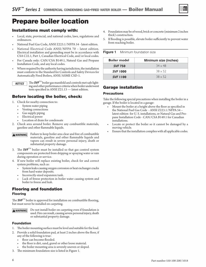
3. The minimum foundation size is listed in Figure 1.
4. Foundation may be of wood, brick or concrete (minimum 2 inches thick) construction.
5. If flooding is possible, elevate boiler sufficiently to prevent water from reaching boiler.
Figure 1 Minimum foundation size
Boiler model Minimum size (inches)
SVF 750 34 x 48
SVF 1000 38 x 52
SVF 1100 38 x 52
Garage installationPrecautions
Take the following special precautions when installing the boiler in a garage. If the boiler is located in a garage:
• Mount the boiler at a height above the floor as specified in the National Fuel Gas Code - ANSI Z223.1/NFPA 54 – latest edition for U. S. installations, or Natural Gas and Pro-pane Installation Code - CAN/CSA B149.1 for Canadian installations.
• Locate or protect the boiler so it cannot be damaged by a moving vehicle.
• Ensure that the installation complies with all applicable codes.
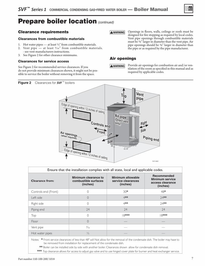
Figure 2 Clearances for SVF TM boilers
Prepare boiler location (continued)
SVF ™ Series 1 COMMERCIAL CONDENSING GAS-FIRED WATER BOILER — Boiler Manual
Part number 550-100-200/1018 7
Clearance requirements
Clearances from combustible materials
1. Hot water pipes — at least 1/2” from combustible materials.2. Vent pipe — at least 3/16” from combustible materials.
- see vent manufacturers instructions.3. See Figure 2 for other clearance minimums.
Clearances for service access
See Figure 2 for recommended service clearances. If you do not provide minimum clearances shown, it might not be pos-sible to service the boiler without removing it from the space.
Openings in floors, walls, ceilings or roofs must be designed for fire stopping as required by local codes. Vent pipe openings through combustible materials must be 3/8” larger in diameter than the vent pipe. Air pipe openings should be 3/8” larger in diameter than the pipe or as required by the pipe manufacturer.
Air openings
Provide air openings for combustion air and/or ven-tilation of the room as specified in this manual and as required by applicable codes.
Ensure that the installation complies with all state, local and applicable codes.
Clearance from:Minimum clearance to combustible surfaces
(inches)
Minimum allowable service clearances
(inches)
RecommendedMinimum service access clearance
(inches)
Controls end (Front) 0 30* 48*
Left side 0 4** 24**
Right side 0 4** 24**
Piping end 24 24 24
Top 0 18*** 18***
Floor 0 — —
Vent pipe 3⁄16 — —
Hot water pipes ½ — —
Notes: * Front service clearances of less than 48" will Not allow for the removal of the condensate dish. The boiler may have to be removed from installation for replacement of the condensate dish.
** Boiler can be installed side by side with another boiler. Clearances shown allow for condensate dish removal.
*** Top clearance allows for access to adjust gas valve and to use hinged cover plate for burner and heat exchanger service.
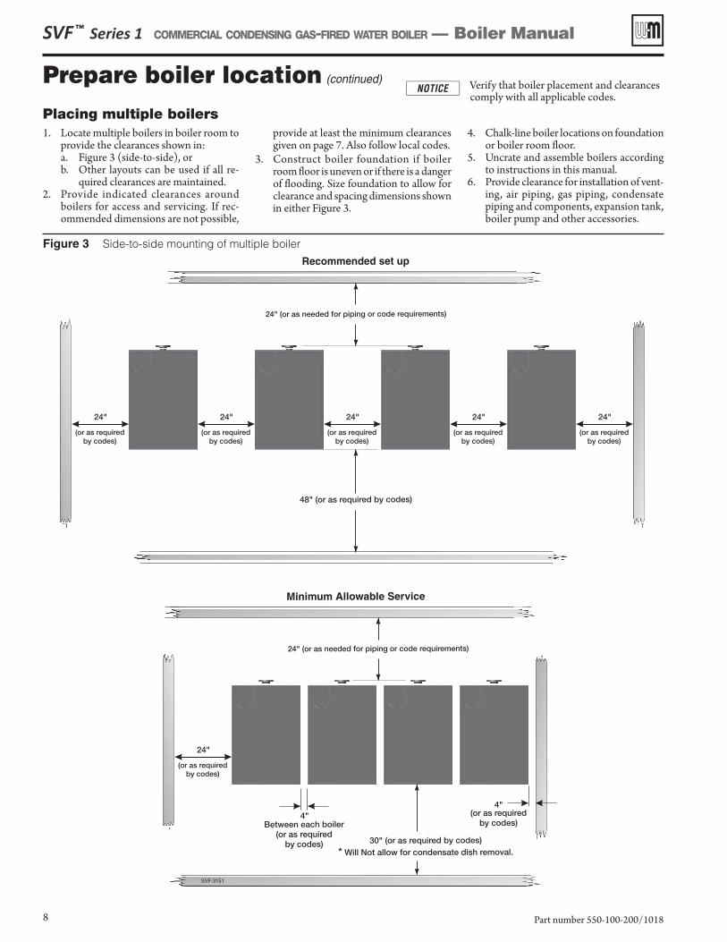
Figure 3 Side-to-side mounting of multiple boiler
SVF ™ Series 1 COMMERCIAL CONDENSING GAS-FIRED WATER BOILER — Boiler Manual
Part number 550-100-200/10188
Placing multiple boilers1. Locate multiple boilers in boiler room to
provide the clearances shown in:a. Figure 3 (side-to-side), orb. Other layouts can be used if all re-
quired clearances are maintained.2. Provide indicated clearances around
boilers for access and servicing. If rec-ommended dimensions are not possible,
provide at least the minimum clearances given on page 7. Also follow local codes.
3. Construct boiler foundation if boiler room floor is uneven or if there is a danger of flooding. Size foundation to allow for clearance and spacing dimensions shown in either Figure 3.
4. Chalk-line boiler locations on foundation or boiler room floor.
5. Uncrate and assemble boilers according to instructions in this manual.
6. Provide clearance for installation of vent-ing, air piping, gas piping, condensate piping and components, expansion tank, boiler pump and other accessories.
Prepare boiler location (continued) Verify that boiler placement and clearances comply with all applicable codes.
SVF ™ Series 1 COMMERCIAL CONDENSING GAS-FIRED WATER BOILER — Boiler Manual
Part number 550-100-200/1018 9
Provide air openings to room
Air openings — General
Follow the National Fuel Gas Code - ANSI Z223.1/NFPA54 – latest edition (U.S.) or Natural Gas and Propane Installation Code - CAN/CSA B149.1 (Canada) and all applicable codes to size/verify size of the combustion/ventilation air openings into the space. See the vent-ing instructions section of this manual for required air openings and sizing for either direct vent or direct exhaust installation.
Vent and air piping requirements (starting on page 22 through page 43)
1. The SVFTM boiler requires a special vent system. a. SVFTM boilers are ANSI Z21.13 rated as Category II , see
page 27. (negative pressure vent, likely to condense in the vent).
Direct-exhaust — vent to the outside, combustion air from inside.
�� SVFTM boilers are ANSI Z21.13 rated as Category IV, see page 36. (positive pressure vent, likely to condense in the vent).
SVFTM commercial boilers can be either: Direct-exhaust — vent to the outside, combustion air from inside or . . . Direct-vent — both vent and air piped outside.
c. See instructions beginning on page 22 for vent/air configura-tion options and installation requirements.
2. Note “Prevention of combustion air contamination” on page 24 when considering vent/air terminations and boiler room condi-tions when using inside air (direct exhaust installation).
3. Be sure to locate the boiler such that the vent and air piping can be routed through the building and properly terminated. The vent/air piping lengths, routing and termination method must all comply with the methods and limits in instructions beginning on page 29.
4. Also locate the boiler such that you have the ability to inspect the vent pipes for leaks or any signs of deteration. Repair or replace as necessary. Inspect and replace any existing vent pipes before installing boiler.
Prepare boiler
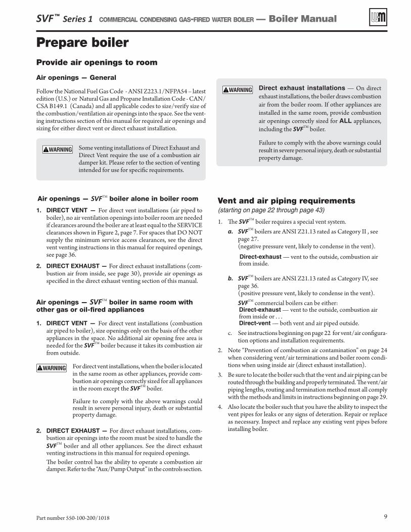
Direct exhaust installations — On direct exhaust installations, the boiler draws combustion air from the boiler room. If other appliances are installed in the same room, provide combustion air openings correctly sized for ALL appliances, including the SVFTM boiler.
Failure to comply with the above warnings could result in severe personal injury, death or substantial property damage.
Some venting installations of Direct Exhaust and Direct Vent require the use of a combustion air damper kit. Please refer to the section of venting intended for use for specific requirements.
Air openings — SVFTM boiler alone in boiler room
1. DIRECT VENT — For direct vent installations (air piped to boiler), no air ventilation openings into boiler room are needed if clearances around the boiler are at least equal to the SERVICE clearances shown in Figure 2, page 7. For spaces that DO NOT supply the minimum service access clearances, see the direct vent venting instructions in this manual for required openings, see page 36.
2. DIRECT EXHAUST — For direct exhaust installations (com-bustion air from inside, see page 30), provide air openings as specified in the direct exhaust venting section of this manual.
Air openings — SVFTM boiler in same room with other gas or oil-fired appliances
1. DIRECT VENT — For direct vent installations (combustion air piped to boiler), size openings only on the basis of the other appliances in the space. No additional air opening free area is needed for the SVFTM boiler because it takes its combustion air from outside.
For direct vent installations, when the boiler is located in the same room as other appliances, provide com-bustion air openings correctly sized for all appliances in the room except the SVFTM boiler.
Failure to comply with the above warnings could result in severe personal injury, death or substantial property damage.
2. DIRECT EXHAUST — For direct exhaust installations, com-bustion air openings into the room must be sized to handle the SVFTM boiler and all other appliances. See the direct exhaust venting instructions in this manual for required openings.
The boiler control has the ability to operate a combustion air damper. Refer to the “Aux/Pump Output” in the controls section.
Prepare boiler (continued)
Ramp
Pallet
Apply pressure only to jacket corners when moving
Brackets(right, left & back
side
Notch
SVF ™ Series 1 COMMERCIAL CONDENSING GAS-FIRED WATER BOILER — Boiler Manual
Part number 550-100-200/101810
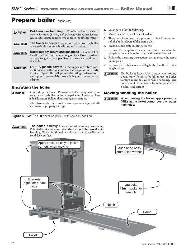
Figure 4 SVF TM 1100 boiler on pallet, with ramp in position
Cold weather handling — If boiler has been stored in a very cold location (below 32°F) before installation, handle with care until the plastic components come to room temperature.
The boiler is heavy. Use caution not to drop the boiler or cause bodily injury while lift ing and handling.
Boiler supply, return and gas pipes — Do not lift or handle the boiler by the water or gas pipes. Do not push on or apply weight to the pipes. Severe damage can be done to the boiler.
Leave the plastic covers on the supply and return con-nections and on the boiler vent and air adapters until ready to att ach piping. Th is will protect the fi tt ings surfaces from damage and prevent debris from falling into the vent or air adapter.
Uncrating the boiler Do not drop the boiler. Damage to boiler components can
result. Leave the boiler on the crate pallet until ready to place in fi nal location. Follow all uncrating instructions.
Failure to comply could result in severe personal injury, death or substantial property damage.
1. See Figure 4 for the following.2. Move the crate to a solid, level surface. 3. Th ere must be room at the piping end to place the ramp and
roll the boiler down off the crate pallet.4. Make sure the crate is sitt ing securely.5. Remove the ramp from the crate and place the end of the
ramp into the notch in the pallet as shown in Figure 4 .6. Follow the uncrating instruction label to secure the ramp
to the pallet.7. Remove the six (6) screws and lag bolts from the six ship-
ping brackets.
Th e boiler is heavy. Use caution when rolling down ramp. Potential bodily injury or boiler damage could be caused while handling. Th e boiler should be unloaded from the pallet on to a solid, level surface.
Moving/handling the boiler When moving the boiler, apply pressure
ONLY at the jacket corner posts or water manifolds.
The boiler is heavy. Use caution when rolling down ramp. Potential bodily injury or boiler damage could be caused while handling. Th e boiler should be unloaded from the pallet onto a solid, level surface.
Allen head bolts5mm Allen wrench
Lag bolts13mm socket or
wrench
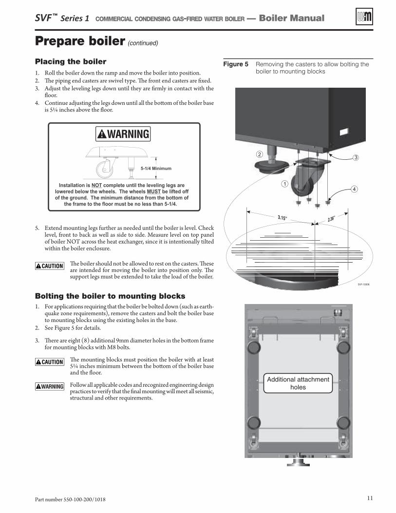
Placing the boiler1. Roll the boiler down the ramp and move the boiler into position.2. The piping end casters are swivel type. The front end casters are fixed.3. Adjust the leveling legs down until they are firmly in contact with the
floor. 4. Continue adjusting the legs down until all the bottom of the boiler base
is 5¼ inches above the floor.
5. Extend mounting legs further as needed until the boiler is level. Check level, front to back as well as side to side. Measure level on top panel of boiler NOT across the heat exchanger, since it is intentionally tilted within the boiler enclosure.
The boiler should not be allowed to rest on the casters. These are intended for moving the boiler into position only. The support legs must be extended to take the load of the boiler.
Bolting the boiler to mounting blocks1. For applications requiring that the boiler be bolted down (such as earth-
quake zone requirements), remove the casters and bolt the boiler base to mounting blocks using the existing holes in the base.
2. See Figure 5 for details.
3. There are eight (8) additional 9mm diameter holes in the bottom frame for mounting blocks with M8 bolts.
The mounting blocks must position the boiler with at least 5¼ inches minimum between the bottom of the boiler base and the floor.
Follow all applicable codes and recognized engineering design practices to verify that the final mounting will meet all seismic, structural and other requirements.
Figure 5 Removing the casters to allow bolting the boiler to mounting blocks
SVF ™ Series 1 COMMERCIAL CONDENSING GAS-FIRED WATER BOILER — Boiler Manual
Part number 550-100-200/1018 11
Prepare boiler (continued)
2.36”3.15”
SVF-10006
2
1
3
4
Additional attachment holes
SVF ™ Series 1 COMMERCIAL CONDENSING GAS-FIRED WATER BOILER — Boiler Manual
Part number 550-100-200/101812
Prepare boiler for propane (when required)
SVFTM boilers must be converted for pro-pane operation — all boilers are shipped ready for natural gas operation, and must be fitted with a propane orifice to be used on propane.
High altitude installations The standard propane orifice is required for
high-altitude installations. The Control automati-cally adjusts boiler operation for altitude when set properly. Select “YES” in the Control setup for the High Altitude option (see Figure 57, page 69).
Verify orifice size Verify when installing the propane orifice that the
orifice size marking matches boiler size. See below.
Converting existing natural gas-fired boiler for propane
For a boiler already installed, you must turn off gas supply, turn off power and allow boiler to cool. Follow the Natural gas to LP conversion procedure below.
Verify operation after conversion You must completely test the boiler after conversion
to verify performance. Start up the boiler following instructions in this manual and the start-up procedure to check combustion levels.
Failure to comply with the above could result in severe personal injury, death or substan-tial property damage.
Propane conversion procedure
If boiler is already installed — You must turn off electrical supply to the boiler and close the external manual gas shut-off valve to isolate the boiler during conversion. Allow the boiler to cool if it has been op-erating. Following conversion of an installed boiler, follow all instructions in this manual to start up the boiler and verify operation of the boiler and all system components.
Natural gas Conversion to Propane1. Locate propane orifice disk from conversion kit bag shipped
with boiler.2. Verify that the stamping on the orifice disk is correct for the
model size.a. 1170 for the SVF 750b. 1250 for the SVF 1000/1100
3. Remove top panela. Remove four (4) screws.b. Lift off panel. Set aside.
4. Remove top front panel.a. Remove two (2) screws.b. Slide up panel and remove from boiler. Set aside.
5. Disconnect gas valve and pressure switch harnesses.6. Remove the ball valve assembly
a. Remove the four (4) M5 bolts attaching the ball valve flange to the gas valve with a 4mm Allen wrench.
b. Remove the four (4) M5 bolts attaching the ball valve flange to the venturi with a 4mm Allen wrench.
c. Lift the ball valve assembly out of place. Set aside.7. Inspect O-ring. If damaged, replace with new.8. Remove cork venturi gasket. Set aside.
a. Inspect gasket. If damaged, replace with new.9. Remove Natural gas orifice.
a. 1550 for the SVF 750 b. 1700 for the SVF 1000/1100
10. Install Propane orifice.a. Ensure correct orifice is installed (see Step 2)!
11. Install ball valve assembly.a. Ensure O-ring is in place on gas valve!b. Install the four (4) M5 bolts attaching the ball valve flange
to the gas valve with a 4mm Allen wrench.c. Ensure cork venturi gasket is in place!d. Install the four (4) M5 bolts and corresponding nuts attach-
ing the ball valve flange to the venturi with a 4mm Allen wrench.
12. Ensure flanges are flat to mounting surfaces and seals, no gaps.13. Reconnect gas valve and pressure switch harnesses.14. Reconnect power.15. Change control to LP settings in either the Wizard or in the boiler
settings menu.16. Start up, test, and adjust boiler as stated in this manual.17. Apply conversion label next to rating label.
Boiler relief valve and P/T gauge DO NOT install a relief valve with a pressure
higher than 160 PSIG. This is the maximum allow-able relief valve setting for the SVFTM boiler. The boiler is shipped with a 30 PSIG relief valve. See Replace-ment parts in the back of this manual for alternate pressure setting relief valves.
The boiler is shipped with a ¼” NPT pressure and temperature gauge which has a pressure range up to 75 psig. This gauge meets ASME requirements up to a relief valve setting of 50 psig. For higher pressure rated relief valves, a different pressure and temperature gauge with a higher pressure range is required. When installing a gauge that requires a larger tapping than the ¼” NPT tapping in the boiler supply manifold, provide an additional tapping in the near boiler piping BEFORE any isolation valve.
Perform hydrostatic pressure testPressure test boiler before permanently attaching water or gas piping or electrical supply.
Each SVFTM boiler is factory tested to 1½ times maximum allowable working pressure per ASME Section IV requirements.
A pressure test should be performed on site to 1½ times the pressure setting of the relief valve to be in-stalled on the unit (45 psig for a 30-psig relief valve; 75 psig for a 50-psig relief valve; or 150 psig for a 100-psig relief valve; or 240 psig for a 160-psig relief valve).
Prepare boiler (continued)
Prepare boiler (continued)
Figure 6 Hydrostatic test piping connections — fl anges, valves and gaskets provided by installer (SVF 1100 shown)
Figure 7 Boiler drain valve tapping – (SVF 1100 shown)
1-inchdrain nipple
SVF ™ Series 1 COMMERCIAL CONDENSING GAS-FIRED WATER BOILER — Boiler Manual
Part number 550-100-200/1018 13
Boiler drain valve (provided by installer)
1. If not installing a drain valve off of the return piping, install a 1-inch boiler drain valve on the 1-inch nipple at the lower left piping end of the heat exchanger (see Figure 7 ).
Prepare boiler for pressure test1. Do Not install relief valve until pressure testing is fi nished.2. See Figure 6, page 13 for reference in following steps. Use pipe
dope sparingly.3. At the boiler supply and return connections, temporarily att ach
blind fl anges, with tapping for a nipple and valve as shown (fl anges, valves, gaskets nipples supplied by installer).
4. Att ach a water supply and hand pump to the lower valves.5. Att ach a drain line to the upper valve.6. Remove the pressure & temperature gauge from the trim box
shipped with the boiler or alternate pressure rating kit.7. Remove the factory-installed plug from the ¼-inch tapping on the
side of the boiler supply pipe.8. Apply pipe dope to the P/T gauge and install in the ¼-inch tap-
ping as shown.9. Install cap on the relief valve nipple, SVF 750 – ¾” NPT and SVF
1000/1100 – 1 ¼” NPT.10. If pressure test will be conducted with a pressure over 160 psig
the automatic air vent must be removed and a 1/2” NPT plug installed in its place.
Fill boiler and pressure test1. Open the shutoff valves installed on the supply and return con-
nections.2. Allow water to fl ow into the bott om connection and air to fl ow out
the top connection.3. When water reaches the shutoff valve on top, allow water to fl ow
long enough to ensure all air is out of the heat exchanger. Th en close the upper shutoff valve.
Ensure all air is purged out of heat exchanger before performing hydrostatic pressure test.
4. Close off the water supply and use hand pump to raise water pres-sure for testing.
5. Th e test pressure should be 1½ times the pressure sett ing of the relief valve to be installed on the boiler (45 psig for a 30-psig relief valve; 75 psig for a 50-psig relief valve; or 150 psig for a 100-psig relief valve; or 240 psig for a 160-psig relief valve).
Th e test pressure MUST NOT exceed the maximum pressure on the P/T gauge. If test pressure will be higher than the maximum range of the P/T gauge, use a diff er-ent gauge for the test or remove gauge and plug tapping.
6. Gradually apply pressure until test pressure is reached. Th en close off the shutoff valve.
7. Hold at test pressure for 10 minutes. Do not leave boiler unatt ended. A cold water fi ll could
expand and cause excessive pressure, resulting in severe personal injury, death or substantial property damage.
8. Make sure that constant gauge pressure has been maintained throughout test.
9. Check for leaks. Repair any leaks from threaded joints. If leaks are found in Heat Exchanger, please consult your Weil-McLain representative.
10. Slowly release pressure and drain. Th e release of high pressure water should be done in
a safe matt er. Failure to do so could resulting in severe personal injury, death or substantial property damage.
11. Re-install Automatic air vent and P/T gauge, if removed.
Leaks must be repaired at once. Failure to do so can damage boiler, resulting in substantial property damage.
Do not use petroleum-based cleaning or sealing compounds in boiler system. Gaskets and seals in the system may be damaged. Th is can result in substantial property damage.
SVF-10007
Automatic Air Vent
Remove relief valve
for test
Install water piping
SVF ™ Series 1 COMMERCIAL CONDENSING GAS-FIRED WATER BOILER — Boiler Manual
Part number 550-100-200/101814
Use two wrenches when tightening water piping at boiler, using one of the wrenches to prevent the boiler interior piping from turning. Failure to support the boiler piping connections to prevent them from turning could cause damage to boiler components.
General piping information
Additional controls, when required
The control module uses temperature sensors to provide both high limit protection and operating limit control, and is UL353 Limit Controls certified to meet ASME CSD-1 and Section IV requirements. The boiler is equipped with a low water cut-off and the manual reset is performed through the control module. Some codes/jurisdictions may require additional external controls.
� Operating limit set point = Supply Max. Temperature + Off differential
Additional limit controls
1. Consult local requirements for other codes/standards to determine if additional limit devices are needed.
Multi-temperature systems — If the heating system includes circuits that require lower temperature water (radi-ant slab circuits, for example) as well as higher temperature circuits, it is recommended to protect low-temperature circuits with limit controls that are wired to a manual or automatic reset circuit on the control.
2. See instructions beginning on page 47 for wiring information.
a. The control provides two (2) sets of limit control contacts — one set will cause automatic reset and the other will cause manual reset of the control.
b. The control can be reset using the manual RESET function on the control display.
Low water cutoff
1. A push-to-test low water cutoff is factory-installed in the boiler. The low water cutoff probe is mounted on the supply outlet pipe at the back of the boiler heat exchanger.
2. The low water cutoff is manual reset through the main control. This can be performed through the display by selecting MANUAL RESET.
Pressure/temperature gauge
1. Mount the pressure/temperature gauge (shipped loose with the boiler) in the ¼-inch port on top of the boiler supply outlet pipe.
The boiler is shipped with a ¼” NPT pressure and tem-perature gauge which has a pressure range up to 75 psig. This gauge meets ASME requirements up to a relief valve setting of 50 psig. For higher pressure rated relief valves, a different pressure and temperature gauge with a higher pressure range is required. When installing a gauge that requires a larger tapping than the ¼” NPT tapping in the boiler supply manifold, provide an additional tapping in the near boiler piping BEFORE any isolation valve.
Backflow preventer1. Use backflow check valve in water fill as required by local
codes.
Install relief valve1. Install relief valve (shipped loose with the boiler) in the
(SVF 750) ¾” or (SVF 1000/1100) 1¼-inch nipple on top of the boiler supply outlet pipe.
2. Connect discharge piping to safe disposal location, following guidelines in the WARNING below.
Installing relief valve
DO NOT install a relief valve with a pressure higher than 160 PSIG. This is the maximum allowable relief valve setting for the SVFTM boiler. The boiler is shipped with a 30 PSIG relief valve. See Replacement parts in the back of this manual for alternate pressure setting relief valves.
To avoid water damage or scalding due to relief valve operation, as per local or state codes:
Discharge line must be connected to relief valve outlet and run to a safe place of disposal. Ter-minate the discharge line in a manner that will prevent possibility of severe burns or property damage should the valve discharge.
Discharge line must be as short as possible and be the same size as the valve discharge connec-tion throughout its entire length.
Discharge line must pitch downward from the valve and terminate at least 6” above the floor drain where any discharge will be clearly visible.
The discharge line shall terminate plain, not threaded, with a material serviceable for tem-peratures of 375 °F or greater.
Do not pipe the discharge to any place where freezing could occur.
No shutoff valve shall be installed between the relief valve and boiler, or in the discharge line. Do not plug or place any obstruction in the discharge line.
Test the operation of the valve after filling and pressurizing system by lifting the lever. Make sure the valve discharges freely. If the valve fails to operate correctly, replace it with a new relief valve.
Failure to comply with the above guidelines could result in failure of the relief valve to oper-ate, resulting in the possibility of severe personal injury, death or substantial property damage.
Install water piping (continued)
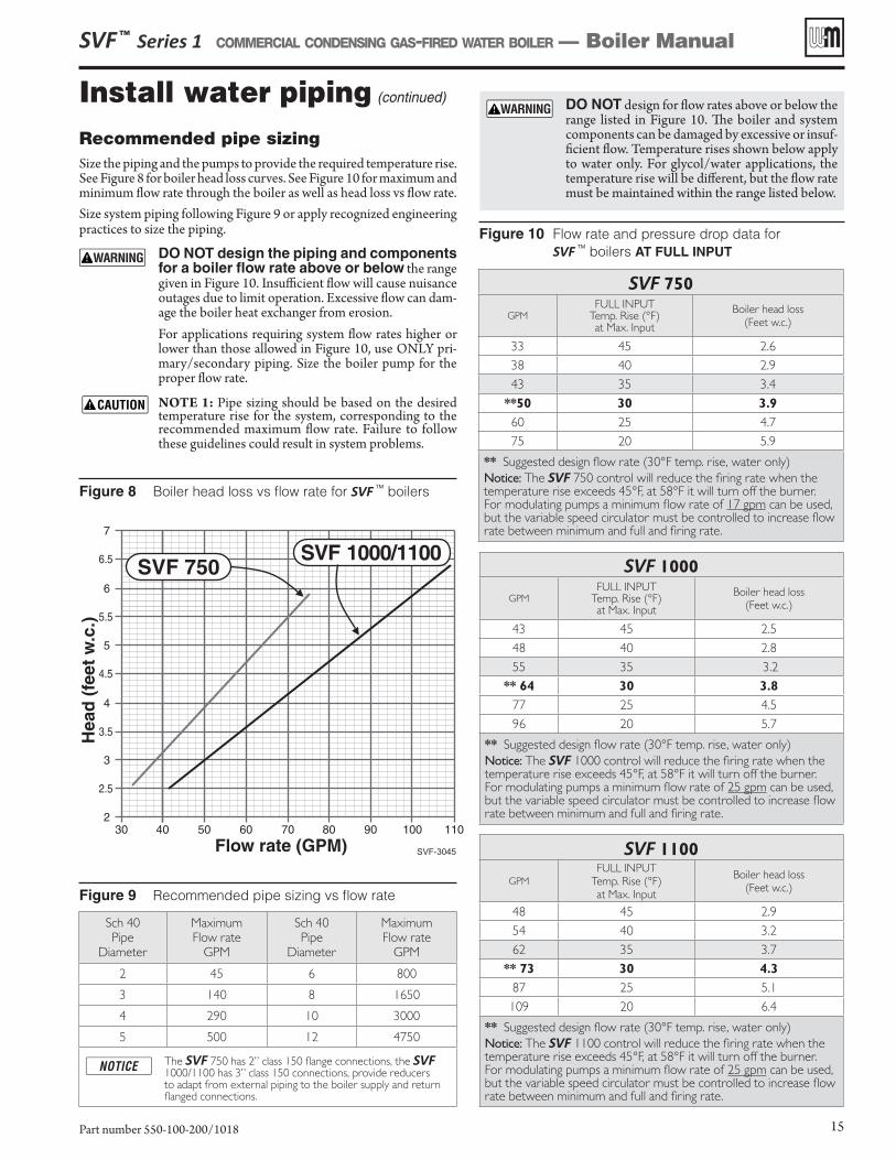
Recommended pipe sizingSize the piping and the pumps to provide the required temperature rise. See Figure 8 for boiler head loss curves. See Figure 10 for maximum and minimum flow rate through the boiler as well as head loss vs flow rate.Size system piping following Figure 9 or apply recognized engineering practices to size the piping.
DO NOT design the piping and components for a boiler flow rate above or below the range given in Figure 10. Insufficient flow will cause nuisance outages due to limit operation. Excessive flow can dam-age the boiler heat exchanger from erosion.For applications requiring system flow rates higher or lower than those allowed in Figure 10, use ONLY pri-mary/secondary piping. Size the boiler pump for the proper flow rate.
NOTE 1: Pipe sizing should be based on the desired temperature rise for the system, corresponding to the recommended maximum flow rate. Failure to follow these guidelines could result in system problems.
Figure 8 Boiler head loss vs flow rate for SVF TM boilers
Figure 9 Recommended pipe sizing vs flow rate
Figure 10 Flow rate and pressure drop data for SVF TM boilers AT FULL INPUT
SVF ™ Series 1 COMMERCIAL CONDENSING GAS-FIRED WATER BOILER — Boiler Manual
Part number 550-100-200/1018 15
Sch 40 Pipe
Diameter
Maximum Flow rate
GPM
Sch 40 Pipe
Diameter
Maximum Flow rate
GPM
2 45 6 800
3 140 8 1650
4 290 10 3000
5 500 12 4750
The SVF 750 has 2” class 150 flange connections, the SVF 1000/1100 has 3” class 150 connections, provide reducers to adapt from external piping to the boiler supply and return flanged connections.
DO NOT design for flow rates above or below the range listed in Figure 10. The boiler and system components can be damaged by excessive or insuf-ficient flow. Temperature rises shown below apply to water only. For glycol/water applications, the temperature rise will be different, but the flow rate must be maintained within the range listed below.
SVF 750
GPMFULL INPUT
Temp. Rise (°F)at Max. Input
Boiler head loss (Feet w.c.)
33 45 2.6
38 40 2.9
43 35 3.4
**50 30 3.9
60 25 4.7
75 20 5.9
** Suggested design flow rate (30°F temp. rise, water only)
Notice: The SVF 750 control will reduce the firing rate when the temperature rise exceeds 45°F, at 58°F it will turn off the burner.For modulating pumps a minimum flow rate of 17 gpm can be used, but the variable speed circulator must be controlled to increase flow rate between minimum and full and firing rate.
SVF 1000
GPMFULL INPUT
Temp. Rise (°F)at Max. Input
Boiler head loss (Feet w.c.)
43 45 2.5
48 40 2.8
55 35 3.2
** 64 30 3.8
77 25 4.5
96 20 5.7
** Suggested design flow rate (30°F temp. rise, water only)
Notice: The SVF 1000 control will reduce the firing rate when the temperature rise exceeds 45°F, at 58°F it will turn off the burner.For modulating pumps a minimum flow rate of 25 gpm can be used, but the variable speed circulator must be controlled to increase flow rate between minimum and full and firing rate.
SVF 1100
GPM
FULL INPUTTemp. Rise (°F)at Max. Input
Boiler head loss (Feet w.c.)
48 45 2.9
54 40 3.2
62 35 3.7
** 73 30 4.3
87 25 5.1
109 20 6.4
** Suggested design flow rate (30°F temp. rise, water only)
Notice: The SVF 1100 control will reduce the firing rate when the temperature rise exceeds 45°F, at 58°F it will turn off the burner.For modulating pumps a minimum flow rate of 25 gpm can be used, but the variable speed circulator must be controlled to increase flow rate between minimum and full and firing rate.
Install water piping (continued)
Expansion tank and make-up water1. Ensure expansion tank size will handle boiler and system water volume
and temperature. See page 114 for boiler water content.
Undersized expansion tanks cause system water to be lost from relief valve and make-up water to be added through fill valve. Eventual boiler failure can result due to excessive make-up water addition.
2. Tank must be located as shown in this manual, or following recognized design methods. See tank manufacturer’s instructions for details.
3. Connect the expansion tank to the air separator only if the separator is on the suction side of the pump. Always install the system fill connec-tion at the same point as the expansion tank connection to the system.
4. Most piping drawings in this manual show diaphragm expansion tanks. See Figure 11 for piping from air separator to expansion tank and make-up water line using a closed-type expansion tank.
5. Most chilled water systems are piped using a closed-type tank, as shown in Figure 17, page 21.
Diaphragm (or bladder) expansion tank
1. (Figure 11) Always install an automatic air vent on top of the air separa-tor to remove residual air from the system.
When using diaphragm or bladder tanks only — when the boiler is installed above the system main piping, install an automatic air vent in the top of the outgoing boiler piping to prevent air pocketing.
The expansion tank needs to be pre-charged to the required system fill pressure before being connected to the system.
Closed-type expansion tank
1. See Figure 12, Alternate, for piping connections when using a closed-type expansion tank.
2. Pitch any horizontal piping up towards tank 1 inch per 5 feet of piping. Connect to tank with at least ¾” piping to allow room for air to rise.
DO NOT install automatic air vents on closed-type expan-sion tank systems. Air must remain in the system and return to the tank to provide its air cushion. An automatic air vent would cause air to leave system, resulting in water-logging the expansion tank.
Figure 11 Expansion tank piping — diaphragm-type expansion tank
SVF-3039a
To systemFrom boiler/system 7
1
3
4
5
8
Figure 12 Expansion tank piping — closed-type expansion tank
SVF ™ Series 1 COMMERCIAL CONDENSING GAS-FIRED WATER BOILER — Boiler Manual
Part number 550-100-200/101816
1 Diaphragm-type expansion tank.2 Closed-type expansion tank.3 Make-up water line.4 Fill valve, typical.5 Air separator.6 Tank fitting.7 System pump (when used).8 Automatic air vent.
To systemFrom boiler/system
2
3
6
78
SVF-3039b
Install water piping (continued)
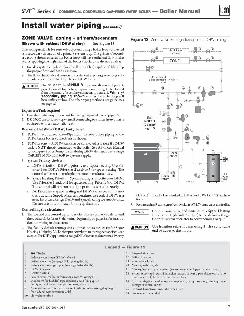
Figure 13 Zone valve zoning plus optional DHW piping
SVF ™ Series 1 COMMERCIAL CONDENSING GAS-FIRED WATER BOILER — Boiler Manual
Part number 550-100-200/1018 17
Legend — Figure 13
1 SVFTM boiler2 Indirect water heater (DHW), if used3 Boiler relief valve (see page 14 for piping details)4 Relief valve discharge piping (see page 14 for details)5 DHW circulator6 Isolation valves7 System circulator (see information above for wiring)8 Diaphragm (or bladder) type expansion tank (see page 16
for piping of closed-type expansion tank, if used)9 Air separator [with automatic air vent only on systems using diaphragm
(or bladder) type expansion tank]10 Flow/check valves
11 Purge/drain valves12 Boiler circulator13 Zone valves, typical20 Make-up water supply21 Primary/secondary connection (tees no more than 8 pipe diameters apart)24 System supply and return immersion sensors, at least 6 pipe diameters (but no
more than 3 feet) from boiler connection tees.25 Systems using high-head pumps may require a bypass pressure regulator to prevent
damage to control valves.26 External drain/blowdown valve, when used.33 Strainer, recommended.
ZONE VALVE zoning – primary/secondary(Shown with optional DHW piping) See Figure 13.
This configuration is for zone valve systems using a boiler loop connected as a secondary circuit off of a primary system loop. The primary/second-ary piping shown ensures the boiler loop will have sufficient flow. It also avoids applying the high head of the boiler circulator to the zone valves.1. Install a system circulator (supplied by installer) capable of delivering
the proper flow and head as shown. 2. The flow/check valve shown on the boiler outlet piping prevents gravity
circulation in the boiler loop during DHW heating. Use at least the MINIMUM pipe size shown in Figure 9,
page 15 on all boiler loop piping (connecting boiler to and from the primary/secondary connection, item 21). Primary/secondary piping shown ensures the boiler loop will have sufficient flow. For other piping methods, see guidelines on page 15.
Expansion Tank required1. Provide a system expansion tank following the guidelines on page 16.2. DO NOT use a closed-type tank if connecting to a water heater that is
equipped with an automatic vent.Domestic Hot Water (DHW) tank, if used1. DHW direct connection—Pipe from the near-boiler piping to the
DHW tank’s boiler connections as shown.2. DHW as zone—A DHW tank can be connected as a zone if a DHW
tank is NOT already connected to the boiler. See Advanced Manual to configure Boiler Pump to run during DHW demands and change TARGET MOD SENSOR to System Supply.
3. System Priority choices: a. DHW Priority – DHW is priority over space heating. Use Pri-
ority 1 for DHW; Priorities 2 and/or 3 for space heating. The control will not run multiple priorities simultaneously.
b. Space Heating Priority – Space heating is priority over DHW. Use Priorities 1 and/or 2 for space heating; Priority 3 for DHW. The control will not run multiple priorities simultaneously.
c. No Priorities – Space heating and DHW can occur simultane-ously at same Supply Max. temperature. Use only if DHW is a zone in system. Assign DHW and Space heating to same Priority. Do not use outdoor reset for this application.
Controlling the circulators1. The control can control up to four circulators (boiler circulator and
three others). Refer to Field wiring, beginning on page 53, for instruc-tions on wiring to circulators.
2. The factory default settings are: all three inputs are set up for Space Heating (Priority 2). Each input correlates to its respective circulator output. For DHW applications, assign DHW inputs to determined Priority
(1, 2 or 3). Priority 1 is defaulted to DHW for DHW Priority applica-tions.
3. For more than 3-zones, use Weil-McLain WMZV zone valve controller.
Connect zone valve end switches to a Space Heating Priority input, (default Priority 2) to use default settings. Connect system circulator to corresponding output.
Use isolation relays if connecting 3-wire zone valve end switches to the inputs.
SVF-3010
510
6
11
11
11
6
10
6 6
Boileroutlet
1
3
4
Boilerreturn
26
SeeNOTE 1“Caution”page 15.
ZONE 1
13 66
66 13
AdditionalZones
25
7
8
20
9
12
33
6
Do not exceed8 pipe diameters
apart21
24 24
11
DHWoutlet
Coldwaterinlet
2
Install water piping (continued)
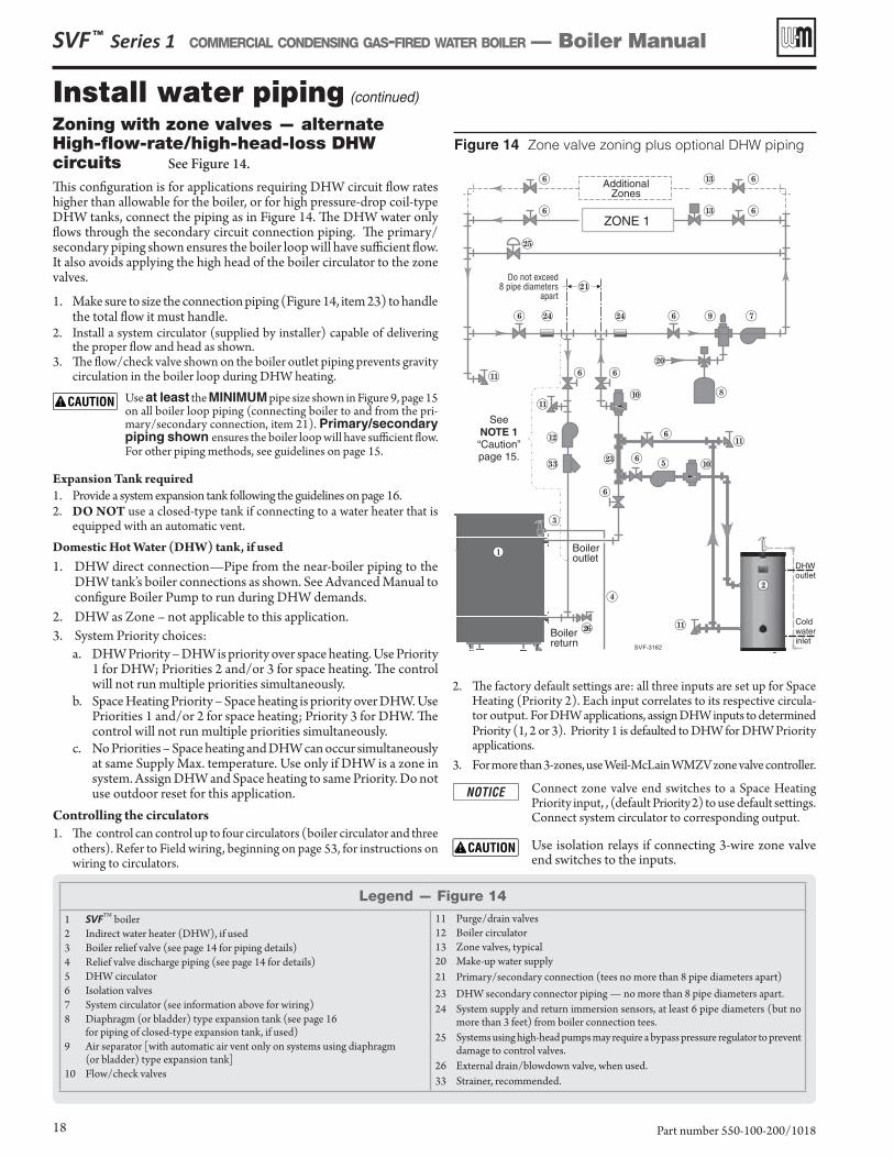
Figure 14 Zone valve zoning plus optional DHW piping
SVF ™ Series 1 COMMERCIAL CONDENSING GAS-FIRED WATER BOILER — Boiler Manual
Part number 550-100-200/101818
Zoning with zone valves — alternate High-flow-rate/high-head-loss DHW circuits See Figure 14.
This configuration is for applications requiring DHW circuit flow rates higher than allowable for the boiler, or for high pressure-drop coil-type DHW tanks, connect the piping as in Figure 14. The DHW water only flows through the secondary circuit connection piping. The primary/secondary piping shown ensures the boiler loop will have sufficient flow. It also avoids applying the high head of the boiler circulator to the zone valves.
1. Make sure to size the connection piping (Figure 14, item 23) to handle the total flow it must handle.
2. Install a system circulator (supplied by installer) capable of delivering the proper flow and head as shown.
3. The flow/check valve shown on the boiler outlet piping prevents gravity circulation in the boiler loop during DHW heating.
Use at least the MINIMUM pipe size shown in Figure 9, page 15 on all boiler loop piping (connecting boiler to and from the pri-mary/secondary connection, item 21). Primary/secondary piping shown ensures the boiler loop will have sufficient flow. For other piping methods, see guidelines on page 15.
Expansion Tank required1. Provide a system expansion tank following the guidelines on page 16.2. DO NOT use a closed-type tank if connecting to a water heater that is
equipped with an automatic vent.Domestic Hot Water (DHW) tank, if used1. DHW direct connection—Pipe from the near-boiler piping to the
DHW tank’s boiler connections as shown. See Advanced Manual to configure Boiler Pump to run during DHW demands.
2. DHW as Zone – not applicable to this application.3. System Priority choices:
a. DHW Priority – DHW is priority over space heating. Use Priority 1 for DHW; Priorities 2 and/or 3 for space heating. The control will not run multiple priorities simultaneously.
b. Space Heating Priority – Space heating is priority over DHW. Use Priorities 1 and/or 2 for space heating; Priority 3 for DHW. The control will not run multiple priorities simultaneously.
c. No Priorities – Space heating and DHW can occur simultaneously at same Supply Max. temperature. Use only if DHW is a zone in system. Assign DHW and Space heating to same Priority. Do not use outdoor reset for this application.
Controlling the circulators1. The control can control up to four circulators (boiler circulator and three
others). Refer to Field wiring, beginning on page 53, for instructions on wiring to circulators.
2. The factory default settings are: all three inputs are set up for Space Heating (Priority 2). Each input correlates to its respective circula-tor output. For DHW applications, assign DHW inputs to determined Priority (1, 2 or 3). Priority 1 is defaulted to DHW for DHW Priority applications.
3. For more than 3-zones, use Weil-McLain WMZV zone valve controller.
Connect zone valve end switches to a Space Heating Priority input, , (default Priority 2) to use default settings. Connect system circulator to corresponding output.
Use isolation relays if connecting 3-wire zone valve end switches to the inputs.
Legend — Figure 14
1 SVFTM boiler2 Indirect water heater (DHW), if used3 Boiler relief valve (see page 14 for piping details)4 Relief valve discharge piping (see page 14 for details)5 DHW circulator6 Isolation valves7 System circulator (see information above for wiring)8 Diaphragm (or bladder) type expansion tank (see page 16
for piping of closed-type expansion tank, if used)9 Air separator [with automatic air vent only on systems using diaphragm
(or bladder) type expansion tank]10 Flow/check valves
11 Purge/drain valves12 Boiler circulator13 Zone valves, typical20 Make-up water supply21 Primary/secondary connection (tees no more than 8 pipe diameters apart)23 DHW secondary connector piping — no more than 8 pipe diameters apart.24 System supply and return immersion sensors, at least 6 pipe diameters (but no
more than 3 feet) from boiler connection tees.25 Systems using high-head pumps may require a bypass pressure regulator to prevent
damage to control valves.26 External drain/blowdown valve, when used.33 Strainer, recommended.
6
6
7
11
8
20
9
25
6
ZONE 1
13 6
613
AdditionalZones
10
6
11
6 6
SeeNOTE 1“Caution”page 15.
Do not exceed8 pipe diameters
apart21
24 246
11
SVF-3162
5 10
11
623
6
Boileroutlet
1
3
4
Boilerreturn
26
12
33
DHWoutlet
Coldwaterinlet
2
Install water piping (continued)
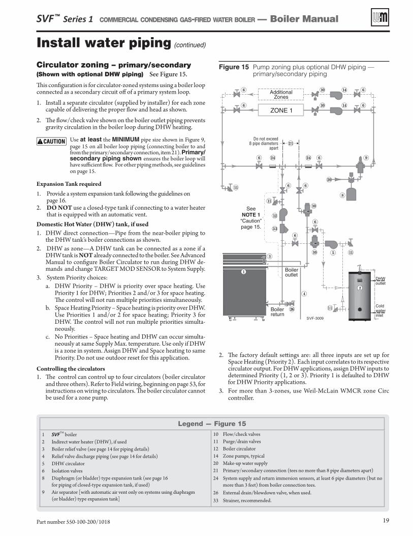
Figure 15 Pump zoning plus optional DHW piping — primary/secondary piping
SVF ™ Series 1 COMMERCIAL CONDENSING GAS-FIRED WATER BOILER — Boiler Manual
Part number 550-100-200/1018 19
Legend — Figure 15
1 SVFTM boiler2 Indirect water heater (DHW), if used3 Boiler relief valve (see page 14 for piping details)4 Relief valve discharge piping (see page 14 for details)5 DHW circulator6 Isolation valves8 Diaphragm (or bladder) type expansion tank (see page 16
for piping of closed-type expansion tank, if used)9 Air separator [with automatic air vent only on systems using diaphragm
(or bladder) type expansion tank]
10 Flow/check valves11 Purge/drain valves12 Boiler circulator14 Zone pumps, typical20 Make-up water supply21 Primary/secondary connection (tees no more than 8 pipe diameters apart)24 System supply and return immersion sensors, at least 6 pipe diameters (but no
more than 3 feet) from boiler connection tees.26 External drain/blowdown valve, when used.33 Strainer, recommended.
Circulator zoning – primary/secondary(Shown with optional DHW piping) See Figure 15.
This configuration is for circulator-zoned systems using a boiler loop connected as a secondary circuit off of a primary system loop.
1. Install a separate circulator (supplied by installer) for each zone capable of delivering the proper flow and head as shown.
2. The flow/check valve shown on the boiler outlet piping prevents gravity circulation in the boiler loop during DHW heating.
Use at least the MINIMUM pipe size shown in Figure 9, page 15 on all boiler loop piping (connecting boiler to and from the primary/secondary connection, item 21). Primary/secondary piping shown ensures the boiler loop will have sufficient flow. For other piping methods, see guidelines on page 15.
Expansion Tank required1. Provide a system expansion tank following the guidelines on
page 16.2. DO NOT use a closed-type tank if connecting to a water heater
that is equipped with an automatic vent.Domestic Hot Water (DHW) tank, if used 1. DHW direct connection—Pipe from the near-boiler piping to
the DHW tank’s boiler connections as shown.2. DHW as zone—A DHW tank can be connected as a zone if a
DHW tank is NOT already connected to the boiler. See Advanced Manual to configure Boiler Circulator to run during DHW de-mands and change TARGET MOD SENSOR to System Supply.
3. System Priority choices: a. DHW Priority – DHW is priority over space heating. Use
Priority 1 for DHW; Priorities 2 and/or 3 for space heating. The control will not run multiple priorities simultaneously.
b. Space Heating Priority – Space heating is priority over DHW. Use Priorities 1 and/or 2 for space heating; Priority 3 for DHW. The control will not run multiple priorities simulta-neously.
c. No Priorities – Space heating and DHW can occur simulta-neously at same Supply Max. temperature. Use only if DHW is a zone in system. Assign DHW and Space heating to same Priority. Do not use outdoor reset for this application.
Controlling the circulators1. The control can control up to four circulators (boiler circulator
and three others). Refer to Field wiring, beginning on page 53, for instructions on wiring to circulators. The boiler circulator cannot be used for a zone pump.
2. The factory default settings are: all three inputs are set up for Space Heating (Priority 2). Each input correlates to its respective circulator output. For DHW applications, assign DHW inputs to determined Priority (1, 2 or 3). Priority 1 is defaulted to DHW for DHW Priority applications.
3. For more than 3-zones, use Weil-McLain WMCR zone Circ controller.
SVF-3009
ZONE 1
6
6 10
6
6
6
14
1410
8
9
510
6
11
20
AdditionalZones
11
11
6
10
6 6
SeeNOTE 1“Caution”page 15.
6
Do not exceed8 pipe diameters
apart21
24 24
11
DHWoutlet
Coldwaterinlet
2
Boileroutlet
1
3
4
Boilerreturn
26
12
33
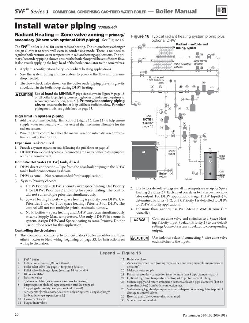
Figure 16 Typical radiant heating system piping plus optional DHW
Install water piping (continued)
Legend — Figure 16
1 SVFTM boiler2 Indirect water heater (DHW), if used3 Boiler relief valve (see page 14 for piping details)4 Relief valve discharge piping (see page 14 for details)5 DHW circulator6 Isolation valves7 System circulator (see information above for wiring)8 Diaphragm (or bladder) type expansion tank (see page 16
for piping of closed-type expansion tank, if used)9 Air separator [with automatic air vent only on systems using diaphragm
(or bladder) type expansion tank]10 Flow/check valves11 Purge/drain valves
12 Boiler circulator13 Zone valves, when used (zoning may also be done using manifold-mounted valve
actuators).20 Make-up water supply21 Primary/secondary connection (tees no more than 8 pipe diameters apart)22 Optional high limit temperature control, set to protect radiant tubing.24 System supply and return immersion sensors, at least 6 pipe diameters (but no
more than 3 feet) from boiler connection tees.25 Systems using high-head pumps may require a bypass pressure regulator to prevent
damage to control valves.26 External drain/blowdown valve, when used.33 Strainer, recommended.
SVF ™ Series 1 COMMERCIAL CONDENSING GAS-FIRED WATER BOILER — Boiler Manual
Part number 550-100-200/101820
Radiant Heating — Zone valve zoning – primary/secondary (Shown with optional DHW piping) See Figure 16.
The SVFTM boiler is ideal for use in radiant heating. The unique heat exchanger design allows it to work well even in condensing mode. There is no need to regulate boiler return water temperature in radiant heating applications. The pri-mary/secondary piping shown ensures the boiler loop will have sufficient flow. It also avoids applying the high head of the boiler circulator to the zone valves.
1. Apply this configuration for typical radiant heating applications. 2. Size the system piping and circulators to provide the flow and pressure
drop needed. 3. The flow/check valve shown on the boiler outlet piping prevents gravity
circulation in the boiler loop during DHW heating.
Use at least the MINIMUM pipe size shown in Figure 9, page 15on all boiler loop piping (connecting boiler to and from the primary/secondary connection, item 21). Primary/secondary piping shown ensures the boiler loop will have sufficient flow. For other piping methods, see guidelines on page 15.
High limit in system piping1. Add the recommended high limit control (Figure 16, item 22) to help ensure
supply water temperature will not exceed the maximum allowable for the radiant system.
2. Wire the limit control to either the manual reset or automatic reset external limit circuit of the Control.
Expansion Tank required1. Provide a system expansion tank following the guidelines on page 16.2. DO NOT use a closed-type tank if connecting to a water heater that is equipped
with an automatic vent.
Domestic Hot Water (DHW) tank, if used1. DHW direct connection—Pipe from the near-boiler piping to the DHW
tank’s boiler connections as shown.2. DHW as zone— Not recommended for this application.3. System Priority choices:
a. DHW Priority – DHW is priority over space heating. Use Priority 1 for DHW; Priorities 2 and/or 3 for space heating. The control will not run multiple priorities simultaneously.
b. Space Heating Priority – Space heating is priority over DHW. Use Priorities 1 and/or 2 for space heating; Priority 3 for DHW. The control will not run multiple priorities simultaneously.
c. No Priorities – Space heating and DHW can occur simultaneously at same Supply Max. temperature. Use only if DHW is a zone in system. Assign DHW and Space heating to same Priority. Do not use outdoor reset for this application.
Controlling the circulators1. The control can control up to four circulators (boiler circulator and three
others). Refer to Field wiring, beginning on page 53, for instructions on wiring to circulators.
2. The factory default settings are: all three inputs are set up for Space Heating (Priority 2). Each input correlates to its respective circu-lator output. For DHW applications, assign DHW Input(s) to determined Priority (1, 2, or 3). Priority 1 is defaulted to DHW for DHW Priority applications.
3. For more than 3-zones, use Weil-McLain WMCR zone Circ controller.
Connect zone valve end switches to a Space Heat-ing Priority input, (default Priority 2) to use default settings Connect system circulator to corresponding output.
Use isolation relays if connecting 3-wire zone valve end switches to the inputs.
SVF-3040
13 6
6
6
613
Radiant manifolds andtubing, typical
Zone valvesoptionalValve actuators
optional
25
6
8
9
510
6
11
20
11
11
6
SeeNOTE 1“Caution”page 15.
10
6 6
21
7
22
6
Do not exceed8 pipe diameters
apart
24 24
11
DHWoutlet
Coldwaterinlet
2
1
3
4
Boilerreturn
26
Boileroutlet
12
33
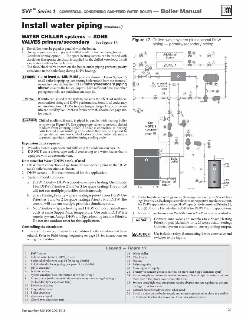
Figure 17 Chilled water system plus optional DHW piping — primary/secondary piping
Install water piping (continued)
SVF ™ Series 1 COMMERCIAL CONDENSING GAS-FIRED WATER BOILER — Boiler Manual
Part number 550-100-200/1018 21
Legend — Figure 171 SVFTM boiler2 Indirect water heater (DHW), if used3 Boiler relief valve (see page 14 for piping details)4 Relief valve discharge piping (see page 14 for details)5 DHW circulator6 Isolation valves7 System circulator (see information above for wiring)9 Air separator [with automatic air vent only on systems using diaphragm
(or bladder) type expansion tank]10 Flow/check valves11 Purge/drain valves12 Boiler circulator13 Zone valves, typical15 Closed-type expansion tank
16 Water chiller17 Check valve18 Strainer19 Balancing valve20 Make-up water supply21 Primary/secondary connection (tees no more than 8 pipe diameters apart)24 System supply and return immersion sensors, at least 6 pipe diameters (but no
more than 3 feet) from boiler connection tees.25 Systems using high-head pumps may require a bypass pressure regulator to prevent
damage to control valves.26 External drain/blowdown valve, when used.31 Install a union on the boiler supply and return connections as close as possible
to the boiler to allow disconnection for service when required.
WATER CHILLER systems — ZONE VALVES primary/secondary See Figure 17.
1. The chiller must be piped in parallel with the boiler. 2. Use appropriate valves to prevent chilled medium from entering boiler.3. Circulator zoning option — The space heating system can be zoned with
circulators if a separate circulator is supplied for the chilled water loop. Install a separate circulator for each zone.
4. The flow/check valve shown on the boiler outlet piping prevents gravity circulation in the boiler loop during DHW heating.
Use at least the MINIMUM pipe size shown in Figure 9, page 15on all boiler loop piping (connecting boiler to and from the primary/secondary connection, item 21). Primary/secondary piping shown ensures the boiler loop will have sufficient flow. For other piping methods, see guidelines on page 15.
If antifreeze is used in the system, consider the effects of antifreeze on circulator sizing and DHW performance. Some local codes may require double-wall DHW heat exchanger design. Use only the an-tifreeze listed by Weil-McLain for use with this boiler. See page 105 for details.
Chilled medium, if used, is piped in parallel with heating boiler as shown in Figure 17. Use appropriate valves to prevent chilled medium from entering boiler. If boiler is connected to heating coils located in air handling units where they can be exposed to refrigerated air, use flow control valves or other automatic means to prevent gravity circulation during cooling cycle.
Expansion Tank required1. Provide a system expansion tank following the guidelines on page 16.2. DO NOT use a closed-type tank if connecting to a water heater that is
equipped with an automatic vent.Domestic Hot Water (DHW) tank, if used1. DHW direct connection—Pipe from the near-boiler piping to the DHW
tank’s boiler connections as shown.2. DHW as zone— Not recommended for this application.3. System Priority choices:
a. DHW Priority – DHW is priority over space heating. Use Priority 1 for DHW; Priorities 2 and/or 3 for space heating. The control will not run multiple priorities simultaneously.
b. Space Heating Priority – Space heating is priority over DHW. Use Priorities 1 and/or 2 for space heating; Priority 3 for DHW. The control will not run multiple priorities simultaneously.
c. No Priorities – Space heating and DHW can occur simultane-ously at same Supply Max. temperature. Use only if DHW is a zone in system. Assign DHW and Space heating to same Priority. Do not use outdoor reset for this application.
Controlling the circulators1. The control can control up to four circulators (boiler circulator and three
others). Refer to Field wiring, beginning on page 53, for instructions on wiring to circulators.
2. The factory default settings are: all three inputs are setup for Space Heat-ing (Priority 2). Each input correlates to its respective circulator output. For DHW applications, assign DHW Input(s) to determined Priority (1, 2, or 3). Priority 1 is defaulted to DHW for DHW Priority applications.
3. For more than 3-zones, use Weil-McLain WMZV zone valve controller.
Connect zone valve end switches to a Space Heating Priority input, (default Priority 2) to use default settings Connect system circulator to corresponding output.
Use isolation relays if connecting 3-wire zone valve end switches to the inputs.
19
ZONE 1
136 6
6 613
15
16
17 186
7
20
AdditionalZones
9
25
SVF-3011
510
6
11
11
11
6
10
6 6
SeeNOTE 1“Caution”page 15.
6
Do not exceed8 pipe diameters
apart
21
24 24
1
3
4
Boilerreturn
26
Boileroutlet
11
DHWoutlet
Coldwaterinlet
2
12
33
Venting/air piping — Massachusetts installations
SVF ™ Series 1 COMMERCIAL CONDENSING GAS-FIRED WATER BOILER — Boiler Manual
Part number 550-100-200/101822
(a) For all sidewall horizontally-vented gas-fueled equipment installed in every dwelling, building or structure used in whole or in part for residential purposes, including those owned or operated by the Commonwealth and where the side wall exhaust vent termina-tion is less than seven (7) feet above finished grade in the area of the venting, including but not limited to decks and porches, the following requirements shall be satisfied:
1. INSTALLATION OF CARBON MONOXIDE DETEC-TORS. At the time of installation of the side wall horizontal vented gas fueled equipment, the installing plumber or gas fit-ter shall observe that a hard wired carbon monoxide detector with an alarm and battery back-up is installed on the floor level where the gas equipment is to be installed. In addition, the installing plumber or gas fitter shall observe that a battery op-erated or hard wired carbon monoxide detector with an alarm is installed on each additional level of the dwelling, building or structure served by the side wall horizontal vented gas fueled equipment. It shall be the responsibility of the property owner to secure the services of qualified licensed professionals for the installation of hard wired carbon monoxide detectors a. In the event that the side wall horizontally vented gas
fueled equipment is installed in a crawl space or an attic, the hard wired carbon monoxide detector with alarm and battery back-up may be installed on the next adjacent floor level.
b. In the event that the requirements of this subdivision can not be met at the time of completion of installation, the owner shall have a period of thirty (30) days to comply with the above requirements; provided, however, that during said thirty (30) day period, a battery operated car-bon monoxide detector with an alarm shall be installed.
2. APPROVED CARBON MONOXIDE DETECTORS. Each carbon monoxide detector as required in accordance with the above provisions shall comply with NFPA 720 and be ANSI/UL 2034 listed and IAS certified.
3. SIGNAGE. A metal or plastic identification plate shall be permanently mounted to the exterior of the building at a minimum height of eight (8) feet above grade directly in line with the exhaust vent terminal for the horizontally vented gas fueled heating appliance or equipment. The sign shall read, in print size no less than one-half (1/2) inch in size, “GAS VENT DIRECTLY BELOW. KEEP CLEAR OF ALL OBSTRUC-TIONS.”
4. INSPECTION. The state or local gas inspector of the side wall horizontally vented gas fueled equipment shall not ap-prove the installation unless, upon inspection, the inspector observes carbon monoxide detectors and signage installed in accordance with the provisions of 248 CMR 5.08(2)(a) 1 through 4.
(b) EXEMPTIONS: The following equipment is exempt from 248 CMR 5.08(2)(a)1 through 4:1. The equipment listed in Chapter 10 entitled “Equipment Not
Required To Be Vented” in the most current edition of NFPA 54 as adopted by the Board; and
2. Product Approved side wall horizontally vented gas fueled equipment installed in a room or structure separate from the dwelling, building or structure used in whole or in part for residential purposes.
(c) MANUFACTURER REQUIREMENTS — GAS EQUIPMENT VENTING SYSTEM PROVIDED. When the manufacturer of Product Approved side wall horizontally vented gas equipment provides a venting system design or venting system components with the equipment, the instructions provided by the manufac-turer for installation of the equipment and the venting system shall include:1. Detailed instructions for the installation of the venting system
design or the venting system components; and2. A complete parts list for the venting system design or venting
system.
(d) MANUFACTURER REQUIREMENTS — GAS EQUIPMENT VENTING SYSTEM NOT PROVIDED. When the manufacturer of a Product Approved side wall horizontally vented gas fueled equipment does not provide the parts for venting the flue gases, but identifies “special venting systems”, the following requirements shall be satisfied by the manufacturer:1. The referenced “special venting system” instructions shall be
included with the appliance or equipment installation instruc-tions; and
2. The “special venting systems” shall be Product Approved by the Board, and the instructions for that system shall include a parts list and detailed installation instructions.
(e) A copy of all installation instructions for all Product Approved side wall horizontally vented gas fueled equipment, all venting instructions, all parts lists for venting instructions, and/or all venting design instructions shall remain with the appliance or equipment at the completion of the installation.
Venting instructions for the installations in the Commonwealth of Massachusetts
Venting/combustion air — general
SVF ™ Series 1 COMMERCIAL CONDENSING GAS-FIRED WATER BOILER — Boiler Manual
Part number 550-100-200/1018 23
SVFTM boilers must be vented and supplied with combustion and ventilation air us-ing piping and methods described in this manual.
DO NOT COMMON VENT Category IV boilers.
Every boiler must have its own vent. DO NOT common vent with any other appliance. See page 26 for checking appliances remaining on a common vent.
INSPECT VENT/AIR COMPONENTS Inspect finished vent and air piping thoroughly to en-
sure all are airtight and comply with the instructions provided and with all requirements of applicable codes. Verify all air openings are correctly sized, unobstructed, and free of airborne contaminants.
Failure to provide a properly-installed vent and air system will cause severe personal injury or death.
DO NOT INSULATE NONMETALLIC VENT PIPE
Do not cover nonmetallic vent pipe with thermal insulation.
Code compliance
Venting/combustion air piping - Installations must provide provisions for combustion and ventilation air in accordance with the section “Air for Com-bustion and Ventilation,” of the National Fuel Gas Code - ANSI Z223.1/NFPA 54 – latest edition, or Sections 8.2, 8.3, or 8.4 of Natural Gas and Propane Installation Code - CAN/CSA B149.1, or applicable provisions of the local building codes.
Vent and air piping materialsUse only the materials listed in this manual (Figure 19, page 25) for vent and air pipe and fittings.
A masonry chimney can ONLY be used as a chase for vent and air piping
If used, a masonry chimney can ONLY be used as a PIPE CHASE for vent and air pipes — The vent and air piping must be installed as instructed in this manual and all joints must be sealed. The chimney must be used only as a chase for the SVFTM boiler vent/air piping. NO OTHER appli-ance or fireplace can be connected to the chimney.
The chimney must be straight, with no offsets, and the vent and air piping materials must comply with this instruction manual.
The chimney must be fitted with a sealed access opening, through which the interior of the chimney can be inspected.
The chimney and liner must be inspected at least once annually to verify condition.
Failure to comply could result in severe personal injury, death or substantial property damage.
Direct Exhaust and Direct Vent consisting of sidewall air intake and through the roof exhaust must use the combustion air damper kit. Failure to do so could result in nuisance shut downs or substantial property damage. See the Replacement Parts section for kit part numbers, Figure 91, page 105.
There are two venting methods available. Follow the instructions on the following pages for the method used.
Method 1: Direct exhaust • Combustion air taken from inside
(no air piping connected to air intake)• Sidewall or vertical termination
Method 2: Direct vent
• Combustion air piped to boiler from outside
• Sidewall or vertical termination
Air openings for direct exhaust
1. Combustion air must be supplied through openings into the boiler room, following the instructions in this manual, and compliant with all applicable codes. Combustion air must not be exposed to any of the contaminants listed in Figure 18, page 24, and ensure the air and boiler room will not contain contaminated air.
2. Where the SVFTM boiler shares a space with other appliances, the combustion air openings must be sized to handle the combined requirements of all appliances in the space.
Combustion air piping for direct vent
1. Combustion air must be piped from outside to the boiler, fol-lowing the instructions in this manual, and compliant with all applicable codes. Read the warning in Figure 18, page 24, and en-sure the air intake will not be likely to draw in contaminated air.
2. Combustion air can be piped individually for each boiler, or it can be manifolded as shown in Figure 28, page 36. Combustion/ventilation openings may also be required in boiler room walls, per instructions in this manual and applicable codes.
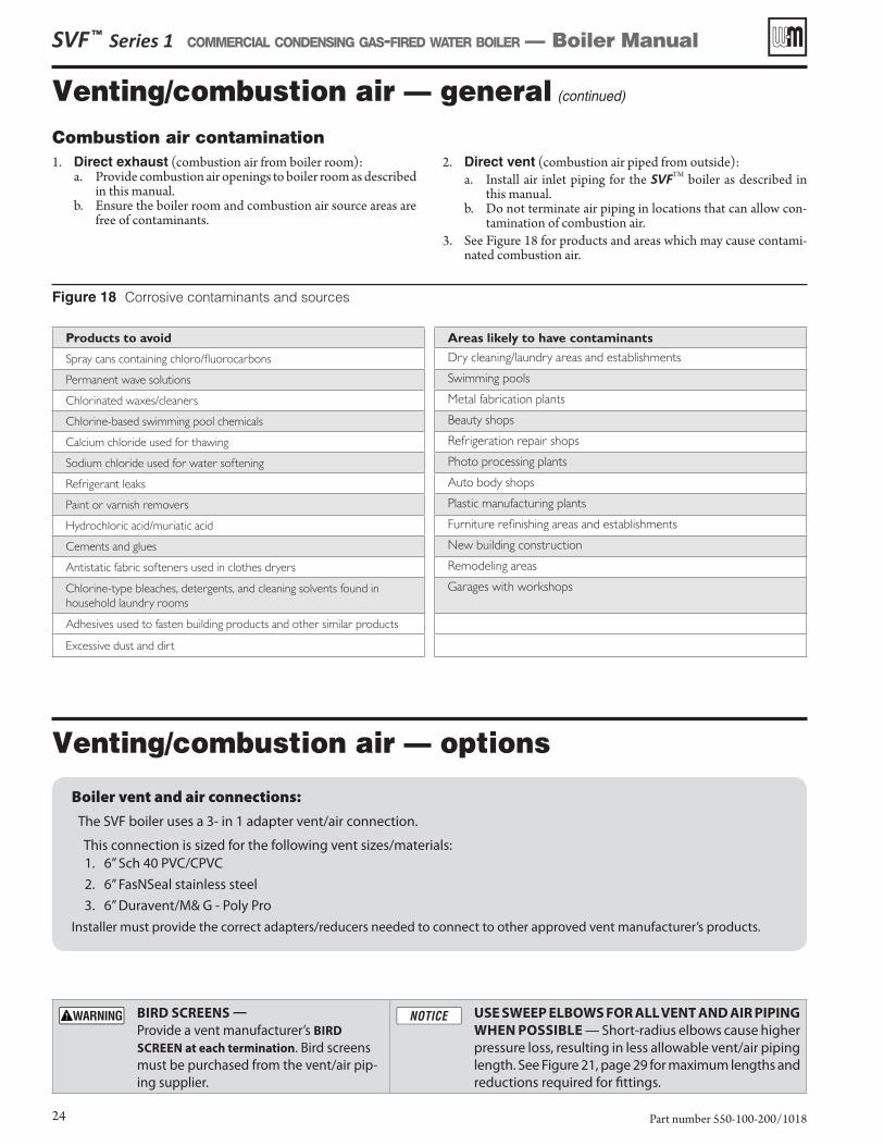
Venting/combustion air — general (continued)
Combustion air contamination1. Direct exhaust (combustion air from boiler room):
a. Provide combustion air openings to boiler room as described in this manual.
b. Ensure the boiler room and combustion air source areas are free of contaminants.
2. Direct vent (combustion air piped from outside):a. Install air inlet piping for the SVFTM boiler as described in
this manual.b. Do not terminate air piping in locations that can allow con-
tamination of combustion air.3. See Figure 18 for products and areas which may cause contami-
nated combustion air.
Boiler vent and air connections:
The SVF boiler uses a 3- in 1 adapter vent/air connection.
This connection is sized for the following vent sizes/materials: 1. 6” Sch 40 PVC/CPVC
2. 6” FasNSeal stainless steel
3. 6” Duravent/M& G - Poly Pro
Installer must provide the correct adapters/reducers needed to connect to other approved vent manufacturer’s products.
Figure 18 Corrosive contaminants and sources
SVF ™ Series 1 COMMERCIAL CONDENSING GAS-FIRED WATER BOILER — Boiler Manual
Part number 550-100-200/101824
Products to avoid Areas likely to have contaminants
Spray cans containing chloro/fluorocarbons Dry cleaning/laundry areas and establishments
Permanent wave solutions Swimming pools
Chlorinated waxes/cleaners Metal fabrication plants
Chlorine-based swimming pool chemicals Beauty shops
Calcium chloride used for thawing Refrigeration repair shops
Sodium chloride used for water softening Photo processing plants
Refrigerant leaks Auto body shops
Paint or varnish removers Plastic manufacturing plants
Hydrochloric acid/muriatic acid Furniture refinishing areas and establishments
Cements and glues New building construction
Antistatic fabric softeners used in clothes dryers Remodeling areas
Chlorine-type bleaches, detergents, and cleaning solvents found in household laundry rooms
Garages with workshops
Adhesives used to fasten building products and other similar products
Excessive dust and dirt
Venting/combustion air — options
BIRD SCREENS
Provide a vent manufacturer’s BIRD
SCREEN at each termination. Bird screens must be purchased from the vent/air pip-ing supplier.
USE SWEEP ELBOWS FOR ALL VENT AND AIR PIPING
WHEN POSSIBLE — Short-radius elbows cause higher pressure loss, resulting in less allowable vent/air piping length. See Figure 21, page 29 for maximum lengths and reductions required for fittings.
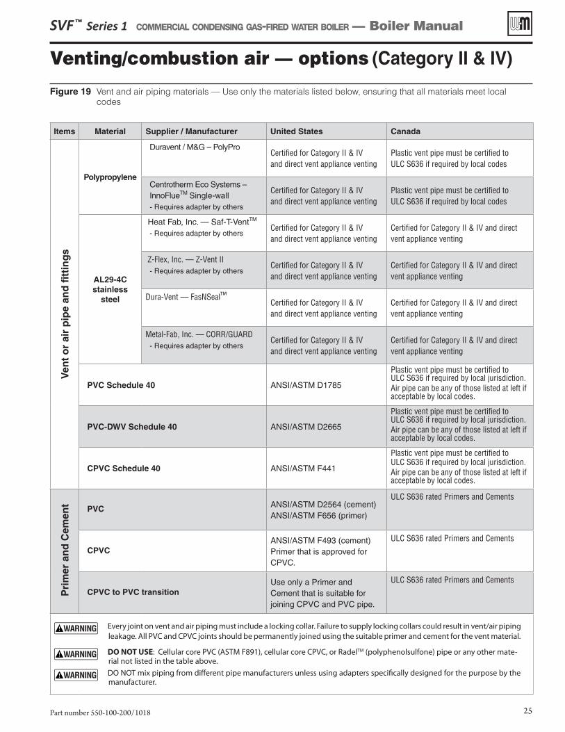
Figure 19 Vent and air piping materials — Use only the materials listed below, ensuring that all materials meet local codes
Venting/combustion air — options (Category II & IV)
SVF ™ Series 1 COMMERCIAL CONDENSING GAS-FIRED WATER BOILER — Boiler Manual
Part number 550-100-200/1018 25
Items Material Supplier / Manufacturer United States Canada
Ven
t o
r ai
r p
ipe
and
fitt
ing
s
Polypropylene
Duravent / M&G – PolyProCertified for Category II & IV and direct vent appliance venting
Plastic vent pipe must be certified to ULC S636 if required by local codes
Centrotherm Eco Systems – InnoFlueTM Single-wall - Requires adapter by others
Certified for Category II & IV and direct vent appliance venting
Plastic vent pipe must be certified to ULC S636 if required by local codes
AL29-4Cstainless
steel
Heat Fab, Inc. — Saf-T-VentTM
- Requires adapter by othersCertified for Category II & IV and direct vent appliance venting
Certified for Category II & IV and direct vent appliance venting
Z-Flex, Inc. — Z-Vent II- Requires adapter by others
Certified for Category II & IV and direct vent appliance venting
Certified for Category II & IV and direct vent appliance venting
Dura-Vent — FasNSeal™Certified for Category II & IV and direct vent appliance venting
Certified for Category II & IV and direct vent appliance venting
Metal-Fab, Inc. — CORR/GUARD- Requires adapter by others
Certified for Category II & IV and direct vent appliance venting
Certified for Category II & IV and direct vent appliance venting
PVC Schedule 40 ANSI/ASTM D1785
Plastic vent pipe must be certified to ULC S636 if required by local jurisdiction. Air pipe can be any of those listed at left if acceptable by local codes.
PVC-DWV Schedule 40 ANSI/ASTM D2665
Plastic vent pipe must be certified to ULC S636 if required by local jurisdiction. Air pipe can be any of those listed at left if acceptable by local codes.
CPVC Schedule 40 ANSI/ASTM F441
Plastic vent pipe must be certified to ULC S636 if required by local jurisdiction. Air pipe can be any of those listed at left if acceptable by local codes.
Pri
mer
an
d C
emen
t PVC ANSI/ASTM D2564 (cement) ANSI/ASTM F656 (primer)
ULC S636 rated Primers and Cements
CPVCANSI/ASTM F493 (cement) Primer that is approved for CPVC.
ULC S636 rated Primers and Cements
CPVC to PVC transitionUse only a Primer and Cement that is suitable for joining CPVC and PVC pipe.
ULC S636 rated Primers and Cements
Every joint on vent and air piping must include a locking collar. Failure to supply locking collars could result in vent/air piping leakage. All PVC and CPVC joints should be permanently joined using the suitable primer and cement for the vent material.
DO NOT USE: Cellular core PVC (ASTM F891), cellular core CPVC, or RadelTM (polyphenolsulfone) pipe or any other mate-rial not listed in the table above.
DO NOT mix piping from different pipe manufacturers unless using adapters specifically designed for the purpose by the manufacturer.
SVF ™ Series 1 COMMERCIAL CONDENSING GAS-FIRED WATER BOILER — Boiler Manual
Part number 550-100-200/101826
Appliances remaining on an existing vent system
Do not install the SVFTM boiler into a common vent with any other appliance. This will cause flue gas spillage or appliance malfunction, resulting in possible severe personal injury, death or substan-tial property damage.
Existing common vent systems may be too large for the appliances remaining connected after the existing boiler is removed.
Failure to follow all instructions can result in flue gas spillage and carbon monoxide emissions, causing severe personal injury or death.
When removing a boiler from an existing common vent system
The SVFTM boiler cannot be common vented with any other appliances. See Category II venting requirements for ad-ditional venting options. When an existing boiler is replaced with a SVFTM boiler, the SVFTM boiler CANNOT use the existing common vent. The SVFTM boiler requires its own vent and air piping, as speci-fied in this manual. This may cause a problem for the appliances that remain on the old common vent, because the vent may be too large. The following test is intended to check for proper operation of the appliances remaining on the old common vent system.
Vent system verification
At the time of removal of an existing boiler, the following steps shall be followed with each appliance remaining connected to the common venting system placed in operation, while the other appliances remain-ing connected to the common venting system are not in operation. Seal any unused openings in the common venting system.
Existing vent test procedure(The following is intended to test whether the appliances remaining on an existing vent system will operate satisfactorily.)
1. Visually inspect the venting system for proper size and horizontal pitch and determine there is no blockage or restriction, leakage, corrosion or other deficiencies which could cause an unsafe condition.
2. Test vent system — Insofar as is practical, close all building doors and windows and all doors between the space in which the appli-ances remaining connected to the common venting system are located and other spaces of the building. Turn on clothes dryers and any appliance not connected to the common venting system. Turn on any exhaust fans, such as range hoods and bathroom exhausts, so they will operate at maximum speed. Do not operate a summer exhaust fan. Close fireplace dampers.
3. Place in operation the appliance being inspected. Follow the lighting instructions. Adjust thermostat so appliance will operate continuously.
4. Test for spillage at draft hood relief opening after 5 minutes of main burner operation. Use the flame of a match or candle, or smoke from a cigarette, cigar, or pipe.
5. After it has been determined that each appliance remaining connected to the common venting system properly vents when tested as outlined herein, return doors, windows, exhaust fans, fireplace dampers, and any other gas-burning appliance to their previous conditions of use.
Any improper operation of the common venting system should be corrected so the installation conforms with the National Fuel Gas Code - ANSI Z223.1/NFPA 54 – latest edition, and/or the Natural Gas and Propane Installation Code, Natural Gas and Propane Instal-lation Code - CAN/CSA B149.1. When resizing any portion of the common venting system, the common venting should be resized to approach the minimum size as determined using the appropriate tables in Chapter 13 of the National Fuel Gas Code - ANSI Z223.1/NFPA 54 – latest edition, and/or the Natural Gas and Propane Instal-lation Code, CAN/CSA B149.1.
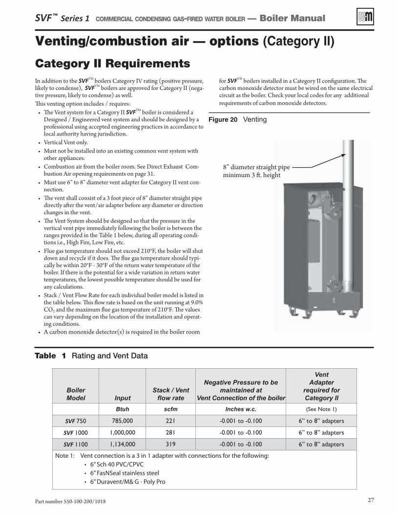
SVF ™ Series 1 COMMERCIAL CONDENSING GAS-FIRED WATER BOILER — Boiler Manual
Part number 550-100-200/1018 27
Venting/combustion air — options (Category II)
In addition to the SVFTM boilers Category IV rating (positive pressure, likely to condense), SVFTM boilers are approved for Category II (nega-tive pressure, likely to condense) as well. This venting option includes / requires:
• The Vent system for a Category II SVFTM boiler is considered a Designed / Engineered vent system and should be designed by a professional using accepted engineering practices in accordance to local authority having jurisdiction.
• Vertical Vent only.• Must not be installed into an existing common vent system with
other appliances.• Combustion air from the boiler room. See Direct Exhaust Com-
bustion Air opening requirements on page 31.• Must use 6” to 8” diameter vent adapter for Category II vent con-
nection.• The vent shall consist of a 3 foot piece of 8” diameter straight pipe
directly after the vent/air adapter before any diameter or direction changes in the vent.
• The Vent System should be designed so that the pressure in the vertical vent pipe immediately following the boiler is between the ranges provided in the Table 1 below, during all operating condi-tions i.e., High Fire, Low Fire, etc.
• Flue gas temperature should not exceed 210°F, the boiler will shut down and recycle if it does. The flue gas temperature should typi-cally be within 20°F - 30°F of the return water temperature of the boiler. If there is the potential for a wide variation in return water temperatures, the lowest possible temperature should be used for any calculations.
• Stack / Vent Flow Rate for each individual boiler model is listed in the table below. This flow rate is based on the unit running at 9.0% CO2 and the maximum flue gas temperature of 210°F. The values can vary depending on the location of the installation and operat-ing conditions.
• A carbon monoxide detector(s) is required in the boiler room
for SVFTM boilers installed in a Category II configuration. The carbon monoxide detector must be wired on the same electrical circuit as the boiler. Check your local codes for any additional requirements of carbon monoxide detectors.
BoilerModel Input
Stack / Vent��������
Negative Pressure to bemaintained at
Vent Connection of the boiler
VentAdapter
required for Category II
Btuh scfm �� ������ (See Note 1)
SVF 750 785,000 221 -0.001 to -0.100 6” to 8” adapters
SVF 1000 1,000,000 281 -0.001 to -0.100 6” to 8” adapters
SVF 1100 1,134,000 319 -0.001 to -0.100 6” to 8” adapters
Note 1: Vent connection is a 3 in 1 adapter with connections for the following: • 6” Sch 40 PVC/CPVC• 6” FasNSeal stainless steel• 6” Duravent/M& G - Poly Pro
Category II Requirements
Table 1 Rating and Vent Data
Figure 20 Venting
8” diameter straight pipeminimum 3 ft. height
SVF ™ Series 1 COMMERCIAL CONDENSING GAS-FIRED WATER BOILER — Boiler Manual
Part number 550-100-200/101828
Venting/combustion air — options (Category II)
Improper Installation of a Category II vent system resulting in positive pressure in the vent system can result in flue gas spillage and carbon monoxide emissions, causing severe personal injury or death.
Weil-McLain recommends the use of a Variable Speed Chimney Fan / Power venter to ensure that the appropriate negative pressure range is kept for Category II venting. The reason this may be needed is due to the higher effi-ciency of the SVFTM boiler. The exhaust gas temperatures are lower which result in less draft when using a chimney fan/power venter. A flow proving switch should be wired into the Closure Switch on terminal block P11 of the boiler. The use of this device should be considered in any engineered vent system in accordance to local authority having jurisdiction.
Weil-McLain recommends the use of a Double Acting Barometric Damper or Modulating Damper to ensure the appropriate negative pressure range is kept for Category II venting. The use of this device should be considered in any engineered vent system in accordance to local authority having jurisdiction.
When using a damper of any kind, it is recommended to use a thermal spill switch to detect any exhaust flow into the boiler room. Verify the temperature range on the thermal spill switch is adequate for the Flue gas temperature from the SVFTM boiler. The use and set-point of this shall be determined by the system designer in accordance to local authority having jurisdiction.
Code Compliance
Venting / Combustion air piping – Installations must provide provisions for combustion and ventilation air in accordance with the section “Venting of Equipment”, of the National Fuel Gas Code, ANSI Z223.1/NFPA 54, or “Venting Systems and Air Supply for appliances” of the Natural Gas and Propane Installation Code, CAN/CSA B149.1, or applicable provisions of the local building codes.
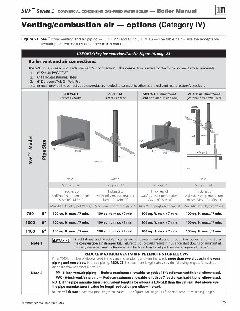
SVF ™ Series 1 COMMERCIAL CONDENSING GAS-FIRED WATER BOILER — Boiler Manual
Part number 550-100-200/1018 29
Venting/combustion air — options (Category IV)
Figure 21 SVF TM boiler venting and air piping — OPTIONS and PIPING LIMITS — The table below lists the acceptable vent/air pipe terminations described in this manual.
USE ONLY the pipe materials listed in Figure 19, page 25
Boiler vent and air connections: The SVF boiler uses a 3- in 1 adapter vent/air connection. This connection is sized for the following vent sizes/ materials:
1. 6” Sch 40 PVC/CPVC2. 6” FasNSeal stainless steel3. 6” Duravent/M& G - Poly Pro
Installer must provide the correct adapters/reducers needed to connect to other approved vent manufacturer’s products.
SVF T
M M
od
el
Pip
e S
ize
SIDEWALL Direct Exhaust
VERTICAL Direct Exhaust
SIDEWALL Direct Vent (vent and air out sidewall)
VERTICAL Direct Vent (vertical or sidewall air)
SF0061deVENT
SF0062de
VENT
VENT
AIR
SF0062
AIR VENT
AIR (option)
Note 1 Note 1 Note 1
See page 34 See page 32 See page 39 See page 41
Thickness of
wall/roof vent penetration;
Max.: 18” Min.: 0”
Thickness of
wall/roof vent penetration;
Max.: 18” Min.: 0”
Thickness of
wall/roof vent penetration;
Max.: 18” Min.: 0”
Thickness of
wall/roof vent penetration;
inches Max.: 18” Min.: 0”
Max./Min. length, feet (Note 2) Max./Min. length, feet (Note 2) Max./Min. length, feet (Note 2) Max./Min. length, feet (Note 2)
750 6” 100 eq. ft. max. / 7 min. 100 eq. ft. max. / 7 min. 100 eq. ft. max. / 7 min. 100 eq. ft. max. / 7 min.
1000 6” 100 eq. ft. max. / 7 min. 100 eq. ft. max. / 7 min. 100 eq. ft. max. / 7 min. 100 eq. ft. max. / 7 min.
1100 6” 100 eq. ft. max. / 7 min. 100 eq. ft. max. / 7 min. 100 eq. ft. max. / 7 min. 100 eq. ft. max. / 7 min.
Note 1 Direct Exhaust and Direct Vent consisting of sidewall air intake and through the roof exhaust must use
the combustion air damper kit. Failure to do so could result in nuisance shut downs or substantial property damage. See the Replacement Parts section for kit part numbers, Figure 91, page 105.
Note 2
REDUCE MAXIMUM VENT/AIR PIPE LENGTHS FOR ELBOWSIf the TOTAL number of elbows used in the vent and air piping and terminations is more than two elbows in the vent
piping and one elbow in the air piping, REDUCE the maximum lengths above by the following lengths for each ad-
ditional elbow (whether 45° or 90°).
PP – 6-inch vent/air piping — Reduce maximum allowable length by 15 feet for each additional elbow used.
PVC – 6-inch vent/air piping — Reduce maximum allowable length by 7 feet for each additional elbow used.
NOTE: If the pipe manufacturer’s equivalent lengths for elbows is LONGER than the values listed above, use
the pipe manufacturer’s value for length reduction per elbow instead.
Boilers will derate as vent/air pipe length increases — see Figure 101, page 114 for derate amount vs piping length.
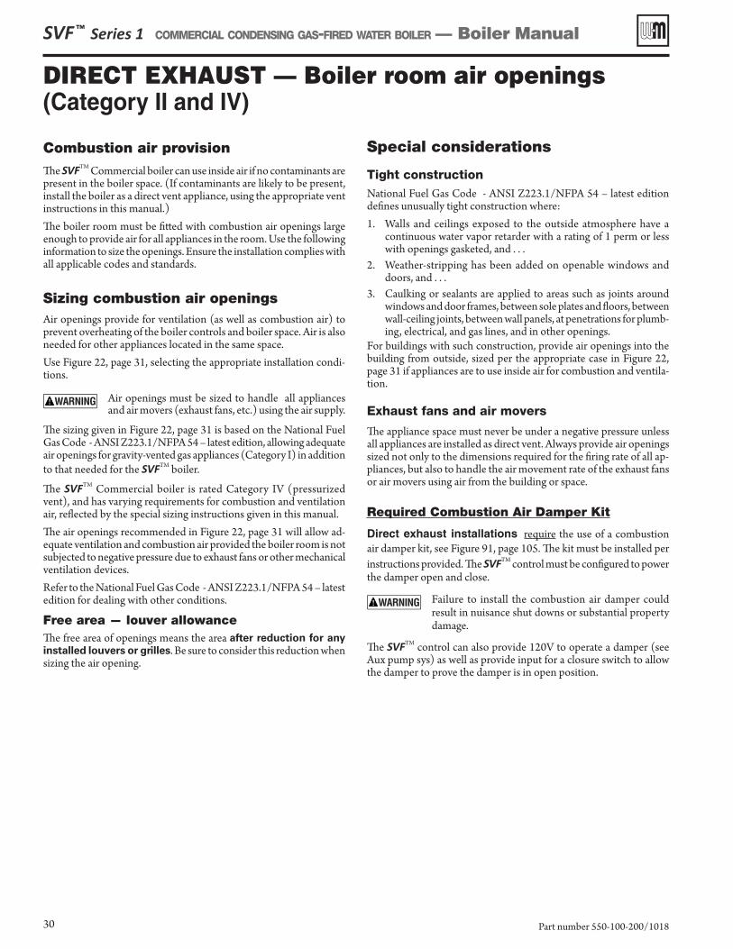
DIRECT EXHAUST — Boiler room air openings (Category II and IV)
SVF ™ Series 1 COMMERCIAL CONDENSING GAS-FIRED WATER BOILER — Boiler Manual
Part number 550-100-200/101830
Combustion air provision
The SVFTM Commercial boiler can use inside air if no contaminants are present in the boiler space. (If contaminants are likely to be present, install the boiler as a direct vent appliance, using the appropriate vent instructions in this manual.)The boiler room must be fitted with combustion air openings large enough to provide air for all appliances in the room. Use the following information to size the openings. Ensure the installation complies with all applicable codes and standards.
Sizing combustion air openingsAir openings provide for ventilation (as well as combustion air) to prevent overheating of the boiler controls and boiler space. Air is also needed for other appliances located in the same space.Use Figure 22, page 31, selecting the appropriate installation condi-tions.
Air openings must be sized to handle all appliances and air movers (exhaust fans, etc.) using the air supply.
The sizing given in Figure 22, page 31 is based on the National Fuel Gas Code - ANSI Z223.1/NFPA 54 – latest edition, allowing adequate air openings for gravity-vented gas appliances (Category I) in addition to that needed for the SVFTM boiler.
The SVFTM Commercial boiler is rated Category IV (pressurized vent), and has varying requirements for combustion and ventilation air, reflected by the special sizing instructions given in this manual.The air openings recommended in Figure 22, page 31 will allow ad-equate ventilation and combustion air provided the boiler room is not subjected to negative pressure due to exhaust fans or other mechanical ventilation devices.Refer to the National Fuel Gas Code - ANSI Z223.1/NFPA 54 – latest edition for dealing with other conditions.
Free area — louver allowanceThe free area of openings means the area after reduction for any
installed louvers or grilles. Be sure to consider this reduction when sizing the air opening.
Special considerations
Tight constructionNational Fuel Gas Code - ANSI Z223.1/NFPA 54 – latest edition defines unusually tight construction where:1. Walls and ceilings exposed to the outside atmosphere have a
continuous water vapor retarder with a rating of 1 perm or less with openings gasketed, and . . .
2. Weather-stripping has been added on openable windows and doors, and . . .
3. Caulking or sealants are applied to areas such as joints around windows and door frames, between sole plates and floors, between wall-ceiling joints, between wall panels, at penetrations for plumb-ing, electrical, and gas lines, and in other openings.
For buildings with such construction, provide air openings into the building from outside, sized per the appropriate case in Figure 22, page 31 if appliances are to use inside air for combustion and ventila-tion.
Exhaust fans and air movers
The appliance space must never be under a negative pressure unless all appliances are installed as direct vent. Always provide air openings sized not only to the dimensions required for the firing rate of all ap-pliances, but also to handle the air movement rate of the exhaust fans or air movers using air from the building or space.
Required Combustion Air Damper Kit
Direct exhaust installations require the use of a combustion air damper kit, see Figure 91, page 105. The kit must be installed per instructions provided. The SVFTM control must be configured to power the damper open and close.
Failure to install the combustion air damper could result in nuisance shut downs or substantial property damage.
The SVFTM control can also provide 120V to operate a damper (see Aux pump sys) as well as provide input for a closure switch to allow the damper to prove the damper is in open position.
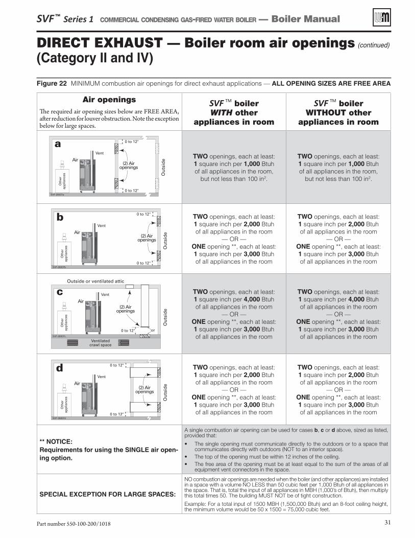
Figure 22 MINIMUM combustion air openings for direct exhaust applications — ALL OPENING SIZES ARE FREE AREA
SVF ™ Series 1 COMMERCIAL CONDENSING GAS-FIRED WATER BOILER — Boiler Manual
Part number 550-100-200/1018 31
Air openingsThe required air opening sizes below are FREE AREA, after reduction for louver obstruction. Note the exception below for large spaces.
SVF TM boiler WITH other
appliances in room
SVF TM boiler WITHOUT other
appliances in room
TWO openings, each at least:1 square inch per 1,000 Btuh of all appliances in the room,
but not less than 100 in2.
TWO openings, each at least:1 square inch per 1,000 Btuh of all appliances in the room,
but not less than 100 in2.
TWO openings, each at least:1 square inch per 2,000 Btuh of all appliances in the room
— OR —ONE opening **, each at least:1 square inch per 3,000 Btuh of all appliances in the room
TWO openings, each at least:1 square inch per 2,000 Btuh of all appliances in the room
— OR —ONE opening **, each at least:1 square inch per 3,000 Btuh of all appliances in the room
TWO openings, each at least:1 square inch per 4,000 Btuh of all appliances in the room
— OR —ONE opening **, each at least:1 square inch per 3,000 Btuh of all appliances in the room
TWO openings, each at least:1 square inch per 4,000 Btuh of all appliances in the room
— OR —ONE opening **, each at least:1 square inch per 3,000 Btuh of all appliances in the room
TWO openings, each at least:1 square inch per 2,000 Btuh of all appliances in the room
— OR —ONE opening **, each at least:1 square inch per 3,000 Btuh of all appliances in the room
TWO openings, each at least:1 square inch per 2,000 Btuh of all appliances in the room
— OR —ONE opening **, each at least:1 square inch per 3,000 Btuh of all appliances in the room
** NOTICE:Requirements for using the SINGLE air open-ing option.
A single combustion air opening can be used for cases b, c or d above, sized as listed, provided that:
• The single opening must communicate directly to the outdoors or to a space that communicates directly with outdoors (NOT to an interior space).
• The top of the opening must be within 12 inches of the ceiling.• The free area of the opening must be at least equal to the sum of the areas of all
equipment vent connectors in the space.
SPECIAL EXCEPTION FOR LARGE SPACES:
NO combustion air openings are needed when the boiler (and other appliances) are installed in a space with a volume NO LESS than 50 cubic feet per 1,000 Btuh of all appliances in the space. That is, total the input of all appliances in MBH (1,000’s of Btuh), then multiply this total times 50. The building MUST NOT be of tight construction.
Example: For a total input of 1500 MBH (1,500,000 Btuh) and an 8-foot ceiling height, the minimum volume would be 50 x 1500 = 75,000 cubic feet.
DIRECT EXHAUST — Boiler room air openings (continued)
(Category II and IV)
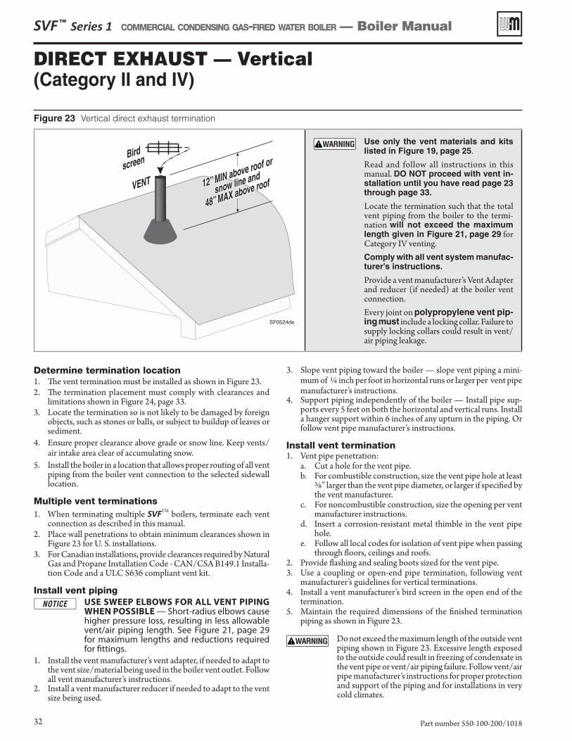
DIRECT EXHAUST — Vertical (Category II and IV)
Figure 23 Vertical direct exhaust termination
Use only the vent materials and kits listed in Figure 19, page 25.
Read and follow all instructions in this manual. DO NOT proceed with vent in-stallation until you have read page 23 through page 33.
Locate the termination such that the total vent piping from the boiler to the termi-nation will not exceed the maximum length given in Figure 21, page 29 for Category IV venting.Comply with all vent system manufac-turer’s instructions.
Provide a vent manufacturer’s Vent Adapter and reducer (if needed) at the boiler vent connection.
Every joint on polypropylene vent pip-ing must include a locking collar. Failure to supply locking collars could result in vent/air piping leakage.
Determine termination location1. The vent termination must be installed as shown in Figure 23.2. The termination placement must comply with clearances and
limitations shown in Figure 24, page 33.3. Locate the termination so is not likely to be damaged by foreign
objects, such as stones or balls, or subject to buildup of leaves or sediment.
4. Ensure proper clearance above grade or snow line. Keep vents/air intake area clear of accumulating snow.
5. Install the boiler in a location that allows proper routing of all vent piping from the boiler vent connection to the selected sidewall location.
Multiple vent terminations1. When terminating multiple SVFTM boilers, terminate each vent
connection as described in this manual.2. Place wall penetrations to obtain minimum clearances shown in
Figure 23 for U. S. installations. 3. For Canadian installations, provide clearances required by Natural
Gas and Propane Installation Code - CAN/CSA B149.1 Installa-tion Code and a ULC S636 compliant vent kit.
Install vent pipingUSE SWEEP ELBOWS FOR ALL VENT PIPING WHEN POSSIBLE — Short-radius elbows cause higher pressure loss, resulting in less allowable vent/air piping length. See Figure 21, page 29for maximum lengths and reductions required for fittings.
1. Install the vent manufacturer’s vent adapter, if needed to adapt to the vent size/material being used in the boiler vent outlet. Follow all vent manufacturer’s instructions.
2. Install a vent manufacturer reducer if needed to adapt to the vent size being used.
3. Slope vent piping toward the boiler — slope vent piping a mini-mum of ¼ inch per foot in horizontal runs or larger per vent pipe manufacturer’s instructions.
4. Support piping independently of the boiler — Install pipe sup-ports every 5 feet on both the horizontal and vertical runs. Install a hanger support within 6 inches of any upturn in the piping. Or follow vent pipe manufacturer’s instructions.
Install vent termination1. Vent pipe penetration:
a. Cut a hole for the vent pipe.b. For combustible construction, size the vent pipe hole at least
3/8” larger than the vent pipe diameter, or larger if specified by the vent manufacturer.
c. For noncombustible construction, size the opening per vent manufacturer instructions.
d. Insert a corrosion-resistant metal thimble in the vent pipe hole.
e. Follow all local codes for isolation of vent pipe when passing through floors, ceilings and roofs.
2. Provide flashing and sealing boots sized for the vent pipe.3. Use a coupling or open-end pipe termination, following vent
manufacturer’s guidelines for vertical terminations. 4. Install a vent manufacturer’s bird screen in the open end of the
termination. 5. Maintain the required dimensions of the finished termination
piping as shown in Figure 23.
Do not exceed the maximum length of the outside vent piping shown in Figure 23. Excessive length exposed to the outside could result in freezing of condensate in the vent pipe or vent/air piping failure. Follow vent/air pipe manufacturer’s instructions for proper protection and support of the piping and for installations in very cold climates.
SVF ™ Series 1 COMMERCIAL CONDENSING GAS-FIRED WATER BOILER — Boiler Manual
Part number 550-100-200/101832
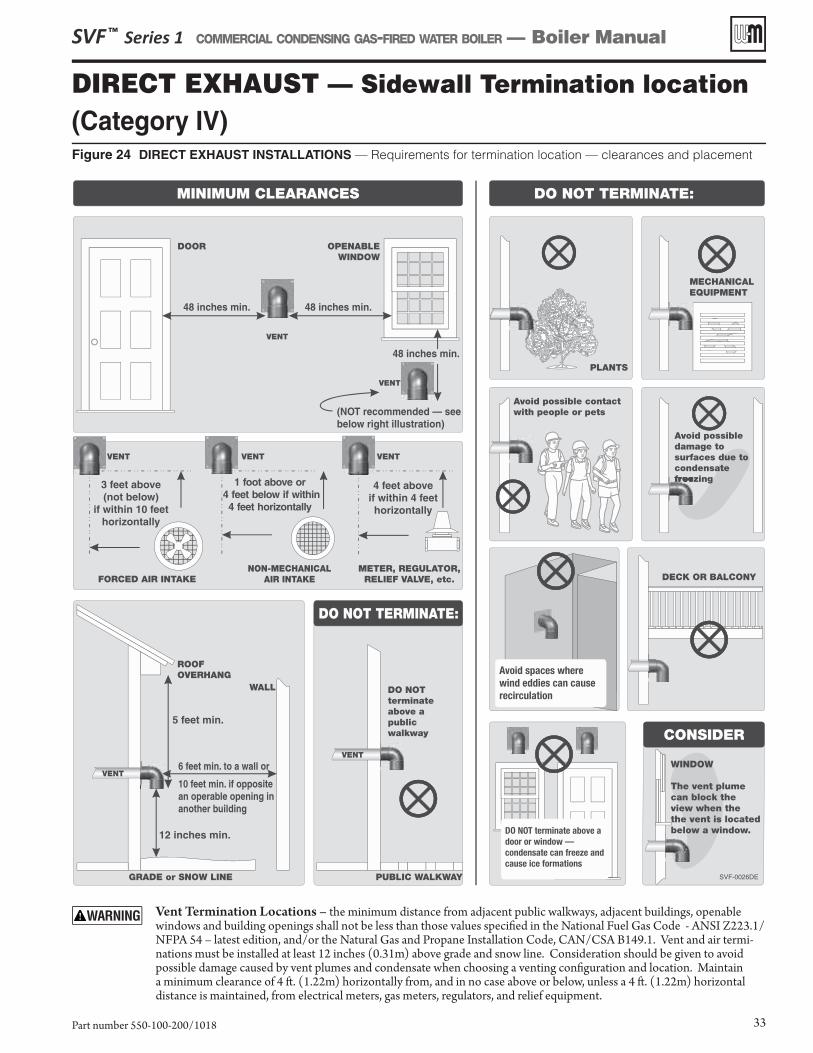
DIRECT EXHAUST — Sidewall Termination location(Category IV) Figure 24 DIRECT EXHAUST INSTALLATIONS — Requirements for termination location — clearances and placement
SVF ™ Series 1 COMMERCIAL CONDENSING GAS-FIRED WATER BOILER — Boiler Manual
Part number 550-100-200/1018 33
Vent Termination Locations – the minimum distance from adjacent public walkways, adjacent buildings, openable windows and building openings shall not be less than those values specifi ed in the National Fuel Gas Code - ANSI Z223.1/NFPA 54 – latest edition, and/or the Natural Gas and Propane Installation Code, CAN/CSA B149.1. Vent and air termi-nations must be installed at least 12 inches (0.31m) above grade and snow line. Consideration should be given to avoid possible damage caused by vent plumes and condensate when choosing a venting confi guration and location. Maintain a minimum clearance of 4 ft . (1.22m) horizontally from, and in no case above or below, unless a 4 ft . (1.22m) horizontal distance is maintained, from electrical meters, gas meters, regulators, and relief equipment.
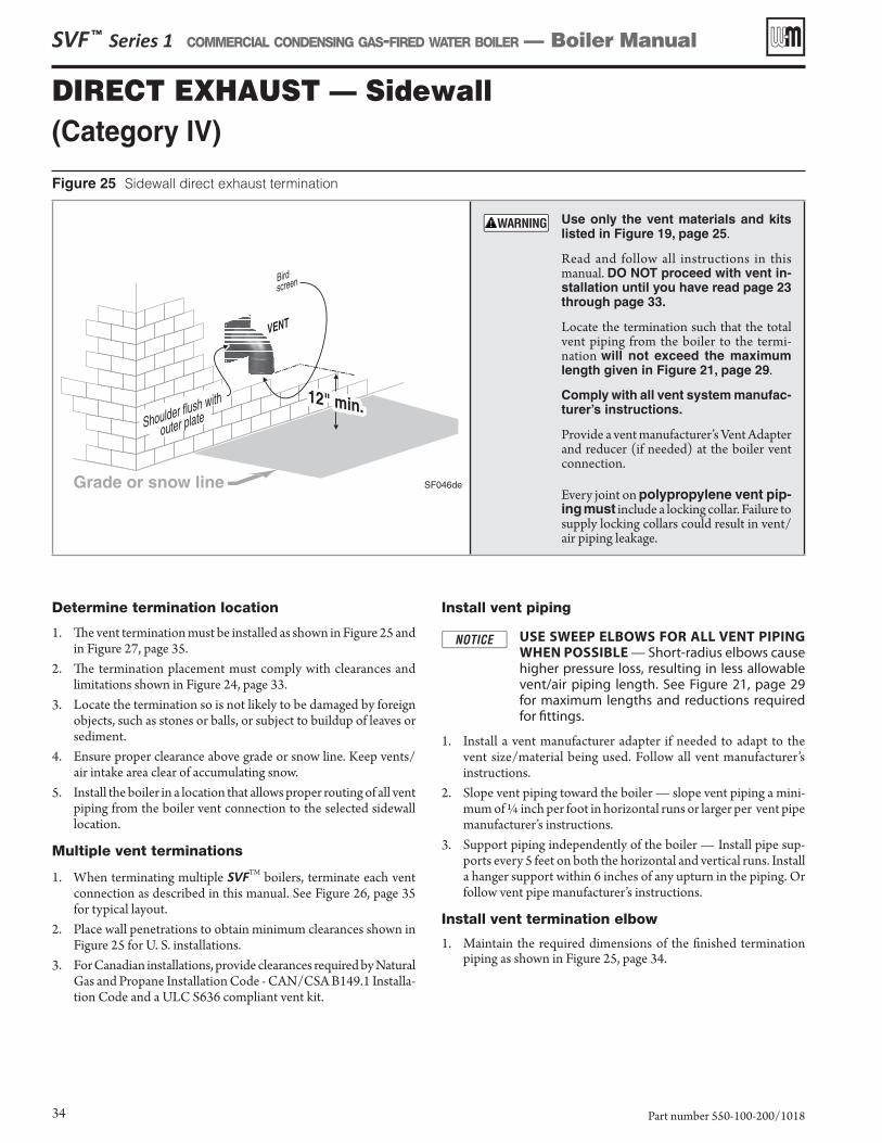
DIRECT EXHAUST — Sidewall (Category IV)
Determine termination location
1. The vent termination must be installed as shown in Figure 25 and in Figure 27, page 35.
2. The termination placement must comply with clearances and limitations shown in Figure 24, page 33.
3. Locate the termination so is not likely to be damaged by foreign objects, such as stones or balls, or subject to buildup of leaves or sediment.
4. Ensure proper clearance above grade or snow line. Keep vents/air intake area clear of accumulating snow.
5. Install the boiler in a location that allows proper routing of all vent piping from the boiler vent connection to the selected sidewall location.
Multiple vent terminations
1. When terminating multiple SVFTM boilers, terminate each vent connection as described in this manual. See Figure 26, page 35 for typical layout.
2. Place wall penetrations to obtain minimum clearances shown in Figure 25 for U. S. installations.
3. For Canadian installations, provide clearances required by Natural Gas and Propane Installation Code - CAN/CSA B149.1 Installa-tion Code and a ULC S636 compliant vent kit.
Install vent piping
USE SWEEP ELBOWS FOR ALL VENT PIPING WHEN POSSIBLE — Short-radius elbows cause higher pressure loss, resulting in less allowable vent/air piping length. See Figure 21, page 29for maximum lengths and reductions required for fittings.
1. Install a vent manufacturer adapter if needed to adapt to the vent size/material being used. Follow all vent manufacturer’s instructions.
2. Slope vent piping toward the boiler — slope vent piping a mini-mum of ¼ inch per foot in horizontal runs or larger per vent pipe manufacturer’s instructions.
3. Support piping independently of the boiler — Install pipe sup-ports every 5 feet on both the horizontal and vertical runs. Install a hanger support within 6 inches of any upturn in the piping. Or follow vent pipe manufacturer’s instructions.
Install vent termination elbow
1. Maintain the required dimensions of the finished termination piping as shown in Figure 25, page 34.
Figure 25 Sidewall direct exhaust termination
Use only the vent materials and kits listed in Figure 19, page 25.
Read and follow all instructions in this manual. DO NOT proceed with vent in-stallation until you have read page 23 through page 33.
Locate the termination such that the total vent piping from the boiler to the termi-nation will not exceed the maximum length given in Figure 21, page 29.
Comply with all vent system manufac-turer’s instructions.
Provide a vent manufacturer’s Vent Adapter and reducer (if needed) at the boiler vent connection.
Every joint on polypropylene vent pip-ing must include a locking collar. Failure to supply locking collars could result in vent/air piping leakage.
SVF ™ Series 1 COMMERCIAL CONDENSING GAS-FIRED WATER BOILER — Boiler Manual
Part number 550-100-200/101834
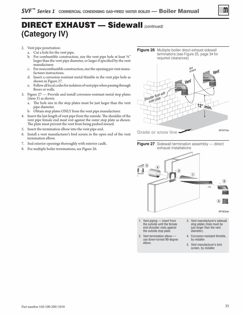
DIRECT EXHAUST — Sidewall (continued)
(Category IV)
Figure 26 Multiple boiler direct exhaust sidewall terminations (see Figure 25, page 34 for required clearances)
Figure 27 Sidewall termination assembly — direct exhaust installations
1. Vent piping — insert from the outside until the female end shoulder rests against the outside stop plate.
2. Vent termination elbow — use down-turned 90-degree elbow.
3. Vent manufacturer’s sidewall stop plates (hole must be just larger than the vent diameter).
4. Corrosion-resistant thimble, by installer.
5. Vent manufacturer’s bird screen, by installer.
2. Vent pipe penetration:a. Cut a hole for the vent pipe. b. For combustible construction, size the vent pipe hole at least 3/8”
larger than the vent pipe diameter, or larger if specified by the vent manufacturer.
c. For noncombustible construction, size the opening per vent manu-facturer instructions.
d. Insert a corrosion-resistant metal thimble in the vent pipe hole as shown in Figure 27.
e. Follow all local codes for isolation of vent pipe when passing through floors or walls.
3. Figure 27 — Provide and install corrosion-resistant metal stop plates (item 3) as shown. a. The hole size in the stop plates must be just larger than the vent
pipe diameter. b. Obtain stop plates ONLY from the vent pipe manufacturer.
4. Insert the last length of vent pipe from the outside. The shoulder of the vent pipe female end must rest against the outer stop plate as shown. The plate must prevent the vent from being pushed inward.
5. Insert the termination elbow into the vent pipe end.6. Install a vent manufacturer’s bird screen in the open end of the vent
termination elbow.7. Seal exterior openings thoroughly with exterior caulk.8. For multiple boiler terminations, see Figure 26.
SVF ™ Series 1 COMMERCIAL CONDENSING GAS-FIRED WATER BOILER — Boiler Manual
Part number 550-100-200/1018 35
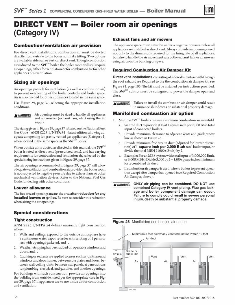
Combustion/ventilation air provisionFor direct vent installations, combustion air must be ducted directly from outside to the boiler air intake fitting. Two options are available: sidewall or vertical direct vent. Though combustion air is ducted to the SVFTM boiler, the boiler room will still require air openings, either for ventilation or for combustion air for other appliances plus ventilation.
Sizing air openingsAir openings provide for ventilation (as well as combustion air) to prevent overheating of the boiler controls and boiler space. Air is also needed for other appliances located in the same space.Use Figure 29, page 37, selecting the appropriate installation conditions.
Air openings must be sized to handle all appliances and air movers (exhaust fans, etc.) using the air supply.
The sizing given in Figure 29, page 37 is based on the National Fuel Gas Code - ANSI Z223.1/NFPA 54 – latest edition, allowing ad-equate air opening for gravity-vented gas appliances (Category I) when located in the same space as the SVFTM boiler.
When outside air is ducted as directed in this manual, the SVFTM boiler is rated as direct vent (pressurized vent), and has varying requirements for combustion and ventilation air, reflected by the special sizing instructions given in Figure 29, page 37. The air openings recommended in Figure 29, page 37 will allow adequate ventilation and combustion air provided the boiler room is not subjected to negative pressure due to exhaust fans or other mechanical ventilation devices. Refer to the National Fuel Gas Code for dealing with other conditions.
Louver allowanceThe free area of openings means the area after reduction for any
installed louvers or grilles. Be sure to consider this reduction when sizing the air openings.
Special considerations
Tight constructionANSI Z223.1/NFPA 54 defines unusually tight construction where:1. Walls and ceilings exposed to the outside atmosphere have
a continuous water vapor retarder with a rating of 1 perm or less with openings gasketed, and . . .
2. Weather-stripping has been added on openable windows and doors, and . . .
3. Caulking or sealants are applied to areas such as joints around windows and door frames, between sole plates and floors, be-tween wall-ceiling joints, between wall panels, at penetrations for plumbing, electrical, and gas lines, and in other openings.
For buildings with such construction, provide air openings into the building from outside, sized per the appropriate case in Fig-ure 29, page 37 if appliances are to use inside air for combustion and ventilation.
Figure 28 Manifolded combustion air option
SVF ™ Series 1 COMMERCIAL CONDENSING GAS-FIRED WATER BOILER — Boiler Manual
Part number 550-100-200/101836
Exhaust fans and air moversThe appliance space must never be under a negative pressure unless all appliances are installed as direct vent. Always provide air openings sized not only to the dimensions required for the firing rate of all appliances, but also to handle the air movement rate of the exhaust fans or air movers using air from the building or space.
Required Combustion Air Damper Kit
Direct vent installations consisting of sidewall air intake with through the roof exhaust are Required to use the combustion air damper kit, see Figure 91, page 105. The kit must be installed per instructions provided. The SVFTM control must be configured to power the damper open and close.
Failure to install the combustion air damper could result in nuisance shut downs or substantial property damage.
Manifolded combustion air option1. Multiple SVFTM boilers can use a common combustion air manifold.
a. Size the duct to provide at least 1 square inch per 2,000 Btuh total input of connected boilers.
b. Provide minimum clearance to adjacent vents and grade/snow line as shown in Figure 28.
c. Provide minimum free area in duct (adjusted for louver restric-tion) of 1 square inch per 2,000 Btuh total boiler input, or divide the total MBH (1000’s Btuh) by 2.
d. Example: For an MBS system with total input of 3,000,000 Btuh, or 3,000 MBH: Divide 3,000 by 2 = 1500 square inches minimum for a combined air duct.
e. If combustion air damper is used, wire to boilers to prevent opera-tion except after damper has opened (see Required Combustion Air Damper, above).
ONLY air piping can be combined. DO NOT use combined Category IV vent piping. Flue gas leak-age and boiler component damage can occur. Failure to comply could result in severe personal injury, death or substantial property damage.
DIRECT VENT — Boiler room air openings (Category IV)
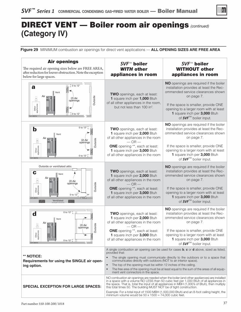
Figure 29 MINIMUM combustion air openings for direct vent applications — ALL OPENING SIZES ARE FREE AREA
SVF ™ Series 1 COMMERCIAL CONDENSING GAS-FIRED WATER BOILER — Boiler Manual
Part number 550-100-200/1018 37
Air openingsThe required air opening sizes below are FREE AREA, after reduction for louver obstruction. Note the exception below for large spaces.
SVFTM boiler WITH other
appliances in room
SVFTM boiler WITHOUT other
appliances in room
TWO openings, each at least:1 square inch per 1,000 Btuh
of all other appliances in the room, but not less than 100 in2.
NO openings are required if the boiler installation provides at least the Rec-
ommended service clearances shown on page 7.
If the space is smaller, provide ONE opening to a larger room with at least
1 square inch per 3,000 Btuh of SVFTM boiler input.
TWO openings, each at least:1 square inch per 2,000 Btuh
of all other appliances in the room— OR —
ONE opening **, each at least:1 square inch per 3,000 Btuh
of all other appliances in the room
NO openings are required if the boiler installation provides at least the Rec-
ommended service clearances shown on page 7.
If the space is smaller, provide ONE opening to a larger room with at least
1 square inch per 3,000 Btuh of SVFTM boiler input.
** NOTICE:Requirements for using the SINGLE air open-ing option.
A single combustion air opening can be used for cases b, c or d above, sized as listed, provided that:
• The single opening must communicate directly to the outdoors or to a space that communicates directly with outdoors (NOT to an interior space).
• The top of the opening must be within 12 inches of the ceiling.• The free area of the opening must be at least equal to the sum of the areas of all equip-
ment vent connectors in the space.
SPECIAL EXCEPTION FOR LARGE SPACES:
NO combustion air openings are needed when the boiler (and other appliances) are installed in a space with a volume NO LESS than 50 cubic feet per 1,000 Btuh of all appliances in the space. That is, total the input of all appliances in MBH (1,000’s of Btuh), then multiply this total times 50. The building MUST NOT be of tight construction.
Example: For a total input of 1500 MBH (1,500,000 Btuh) and an 8-foot ceiling height, the minimum volume would be 50 x 1500 = 74,000 cubic feet.
DIRECT VENT — Boiler room air openings (continued)
(Category IV)
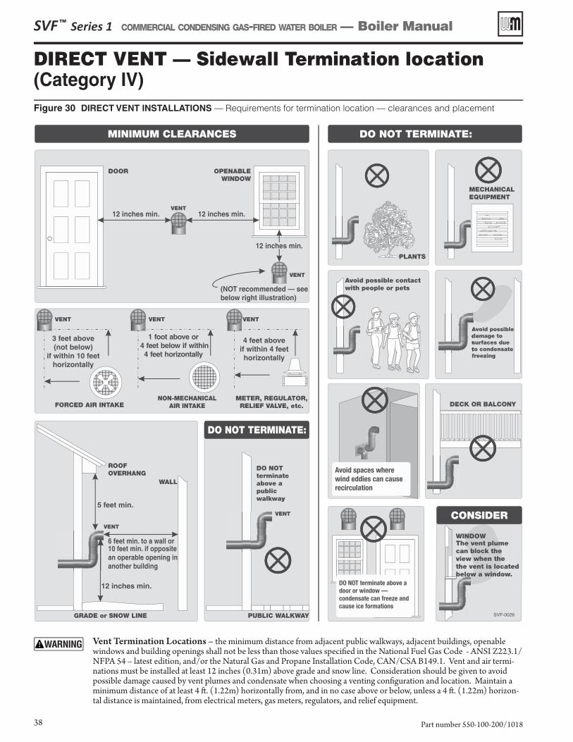
DIRECT VENT — Sidewall Termination location(Category IV)Figure 30 DIRECT VENT INSTALLATIONS — Requirements for termination location — clearances and placement
SVF ™ Series 1 COMMERCIAL CONDENSING GAS-FIRED WATER BOILER — Boiler Manual
Part number 550-100-200/101838
Vent Termination Locations – the minimum distance from adjacent public walkways, adjacent buildings, openable windows and building openings shall not be less than those values specifi ed in the National Fuel Gas Code - ANSI Z223.1/NFPA 54 – latest edition, and/or the Natural Gas and Propane Installation Code, CAN/CSA B149.1. Vent and air termi-nations must be installed at least 12 inches (0.31m) above grade and snow line. Consideration should be given to avoid possible damage caused by vent plumes and condensate when choosing a venting confi guration and location. Maintain a minimum distance of at least 4 ft . (1.22m) horizontally from, and in no case above or below, unless a 4 ft . (1.22m) horizon-tal distance is maintained, from electrical meters, gas meters, regulators, and relief equipment.
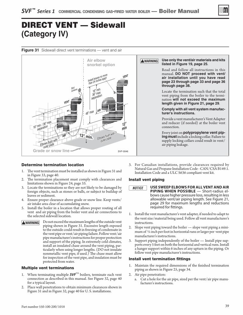
DIRECT VENT — Sidewall (Category IV)
Determine termination location
1. The vent termination must be installed as shown in Figure 31 and in Figure 33, page 40.
2. The termination placement must comply with clearances and limitations shown in Figure 24, page 33.
3. Locate the terminations so they are not likely to be damaged by foreign objects, such as stones or balls, or subject to buildup of leaves or sediment.
4. Ensure proper clearance above grade or snow line. Keep vents/air intake area clear of accumulating snow.
5. Install the boiler in a location that allows proper routing of all vent and air piping from the boiler vent and air connections to the selected sidewall location.
Do not exceed the maximum lengths of the outside vent piping shown in Figure 31. Excessive length exposed to the outside could result in freezing of condensate in the vent pipe or vent/air piping failure. Follow vent/air pipe manufacturer’s instructions for proper protection and support of the piping. In extremely cold climates, install an insulated chase around the vent piping, par-ticularly when using longer lengths. (DO not insulate nonmetallic vent pipe, if used.) The chase must allow for inspection of the vent pipe, and insulation must be protected from water.
Multiple vent terminations
1. When terminating multiple SVFTM boilers, terminate each vent connection as described in this manual. See Figure 32, page 40 for a typical layout.
2. Place wall penetrations to obtain minimum clearances shown in Figure 31 and in Figure 32, page 40 for U. S. installations.
3. For Canadian installations, provide clearances required by Natural Gas and Propane Installation Code - CAN/CSA B149.1. Installation Code and a ULC S636 compliant vent kit.
Install vent piping
USE SWEEP ELBOWS FOR ALL VENT AND AIR PIPING WHEN POSSIBLE — Short-radius el-bows cause higher pressure loss, resulting in less allowable vent/air piping length. See Figure 21, page 29 for maximum lengths and reductions required for fittings.
1. Install the vent manufacturer’s vent adapter, if needed to adapt to the vent size/material being used. Follow all vent manufacturer’s instructions.
2. Slope vent piping toward the boiler — slope vent piping a mini-mum of ¼ inch per foot in horizontal runs or larger per vent pipe manufacturer’s instructions.
3. Support piping independently of the boiler — Install pipe sup-ports every 5 feet on both the horizontal and vertical runs. Install a hanger support within 6 inches of any upturn in the piping. Or follow vent pipe manufacturer’s instructions.
Install vent termination fittings
1. Maintain the required dimensions of the finished termination piping as shown in Figure 25, page 34.
2. Air pipe penetration:a. Cut a hole for the air pipe, sized per the vent/air pipe manu-
facturer’s instructions.
Figure 31 Sidewall direct vent terminations — vent and air
Use only the vent/air materials and kits listed in Figure 19, page 25.
Read and follow all instructions in this manual. DO NOT proceed with vent/air installation until you have read page 23 through page 33 and page 36 through page 38.
Locate the termination such that the total vent piping from the boiler to the termi-nation will not exceed the maximum length given in Figure 21, page 29.Comply with all vent system manufac-turer’s instructions.
Provide a vent manufacturer’s Vent Adapter and reducer (if needed) at the boiler vent connection.
Every joint on polypropylene vent pip-ing must include a locking collar. Failure to supply locking collars could result in vent/air piping leakage.
SVF ™ Series 1 COMMERCIAL CONDENSING GAS-FIRED WATER BOILER — Boiler Manual
Part number 550-100-200/1018 39
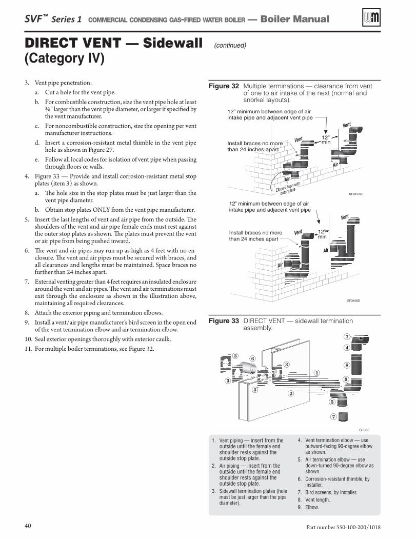
Figure 32 Multiple terminations — clearance from vent of one to air intake of the next (normal and snorkel layouts).
Figure 33 DIRECT VENT — sidewall termination assembly.
3. Vent pipe penetration:a. Cut a hole for the vent pipe. b. For combustible construction, size the vent pipe hole at least
3/8” larger than the vent pipe diameter, or larger if specified by the vent manufacturer.
c. For noncombustible construction, size the opening per vent manufacturer instructions.
d. Insert a corrosion-resistant metal thimble in the vent pipe hole as shown in Figure 27.
e. Follow all local codes for isolation of vent pipe when passing through floors or walls.
4. Figure 33 — Provide and install corrosion-resistant metal stop plates (item 3) as shown. a. The hole size in the stop plates must be just larger than the
vent pipe diameter. b. Obtain stop plates ONLY from the vent pipe manufacturer.
5. Insert the last lengths of vent and air pipe from the outside. The shoulders of the vent and air pipe female ends must rest against the outer stop plates as shown. The plates must prevent the vent or air pipe from being pushed inward.
6. The vent and air pipes may run up as high as 4 feet with no en-closure. The vent and air pipes must be secured with braces, and all clearances and lengths must be maintained. Space braces no further than 24 inches apart.
7. External venting greater than 4 feet requires an insulated enclosure around the vent and air pipes. The vent and air terminations must exit through the enclosure as shown in the illustration above, maintaining all required clearances.
8. Attach the exterior piping and termination elbows.9. Install a vent/air pipe manufacturer’s bird screen in the open end
of the vent termination elbow and air termination elbow.10. Seal exterior openings thoroughly with exterior caulk.11. For multiple boiler terminations, see Figure 32.
SVF ™ Series 1 COMMERCIAL CONDENSING GAS-FIRED WATER BOILER — Boiler Manual
Part number 550-100-200/101840
1. Vent piping — insert from the outside until the female end shoulder rests against the outside stop plate.
2. Air piping — insert from the outside until the female end shoulder rests against the outside stop plate.
3. Sidewall termination plates (hole must be just larger than the pipe diameter).
4. Vent termination elbow — use outward-facing 90-degree elbow as shown.
5. Air termination elbow — use down-turned 90-degree elbow as shown.
6. Corrosion-resistant thimble, by installer.
7. Bird screens, by installer.8. Vent length.9. Elbow.
DIRECT VENT — Sidewall (continued)
(Category IV)
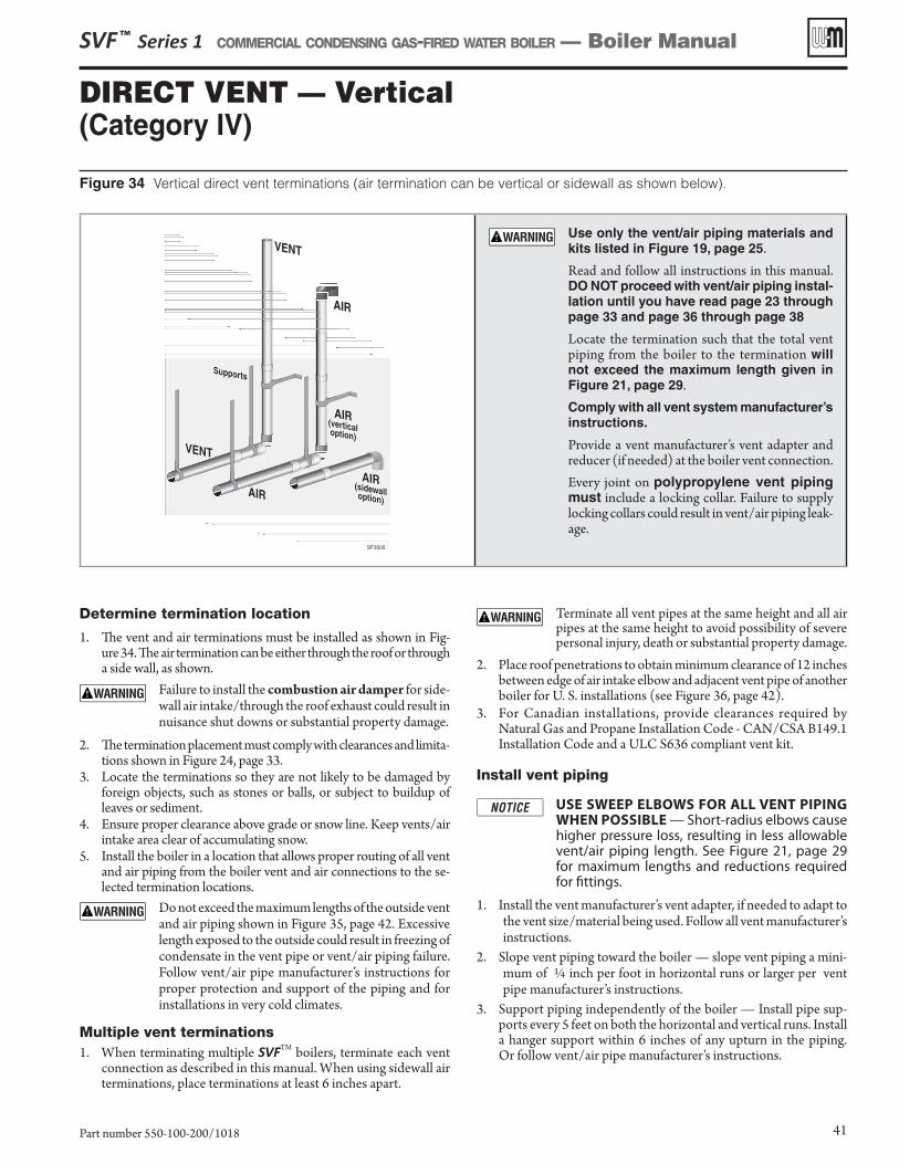
Figure 34 Vertical direct vent terminations (air termination can be vertical or sidewall as shown below).
Use only the vent/air piping materials and kits listed in Figure 19, page 25.
Read and follow all instructions in this manual. DO NOT proceed with vent/air piping instal-lation until you have read page 23 through page 33 and page 36 through page 38
Locate the termination such that the total vent piping from the boiler to the termination will not exceed the maximum length given in Figure 21, page 29.Comply with all vent system manufacturer’s instructions.
Provide a vent manufacturer’s vent adapter and reducer (if needed) at the boiler vent connection.
Every joint on polypropylene vent piping must include a locking collar. Failure to supply locking collars could result in vent/air piping leak-age.
Determine termination location
1. The vent and air terminations must be installed as shown in Fig-ure 34. The air termination can be either through the roof or through a side wall, as shown.
Failure to install the combustion air damper for side-wall air intake/through the roof exhaust could result in nuisance shut downs or substantial property damage.
2. The termination placement must comply with clearances and limita-tions shown in Figure 24, page 33.
3. Locate the terminations so they are not likely to be damaged by foreign objects, such as stones or balls, or subject to buildup of leaves or sediment.
4. Ensure proper clearance above grade or snow line. Keep vents/air intake area clear of accumulating snow.
5. Install the boiler in a location that allows proper routing of all vent and air piping from the boiler vent and air connections to the se-lected termination locations.
Do not exceed the maximum lengths of the outside vent and air piping shown in Figure 35, page 42. Excessive length exposed to the outside could result in freezing of condensate in the vent pipe or vent/air piping failure. Follow vent/air pipe manufacturer’s instructions for proper protection and support of the piping and for installations in very cold climates.
Multiple vent terminations1. When terminating multiple SVFTM boilers, terminate each vent
connection as described in this manual. When using sidewall air terminations, place terminations at least 6 inches apart.
Terminate all vent pipes at the same height and all air pipes at the same height to avoid possibility of severe personal injury, death or substantial property damage.
2. Place roof penetrations to obtain minimum clearance of 12 inches between edge of air intake elbow and adjacent vent pipe of another boiler for U. S. installations (see Figure 36, page 42).
3. For Canadian installations, provide clearances required by Natural Gas and Propane Installation Code - CAN/CSA B149.1 Installation Code and a ULC S636 compliant vent kit.
Install vent piping
USE SWEEP ELBOWS FOR ALL VENT PIPING WHEN POSSIBLE — Short-radius elbows cause higher pressure loss, resulting in less allowable vent/air piping length. See Figure 21, page 29for maximum lengths and reductions required for fittings.
1. Install the vent manufacturer’s vent adapter, if needed to adapt to the vent size/material being used. Follow all vent manufacturer’s instructions.
2. Slope vent piping toward the boiler — slope vent piping a mini-mum of ¼ inch per foot in horizontal runs or larger per vent pipe manufacturer’s instructions.
3. Support piping independently of the boiler — Install pipe sup-ports every 5 feet on both the horizontal and vertical runs. Install a hanger support within 6 inches of any upturn in the piping. Or follow vent/air pipe manufacturer’s instructions.
SVF ™ Series 1 COMMERCIAL CONDENSING GAS-FIRED WATER BOILER — Boiler Manual
Part number 550-100-200/1018 41
DIRECT VENT — Vertical(Category IV)
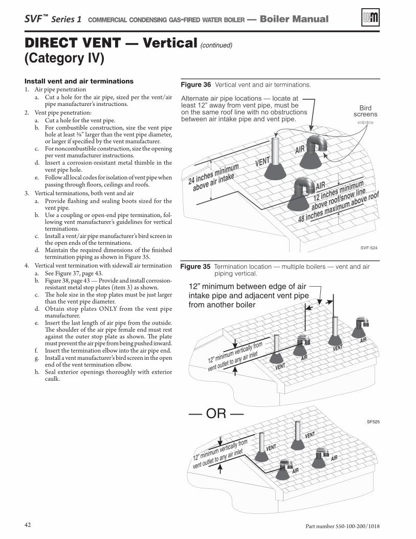
Install vent and air ter minations1. Air pipe penetration
a. Cut a hole for the air pipe, sized per the vent/air pipe manufacturer’s instructions.
2. Vent pipe penetration:a. Cut a hole for the vent pipe.b. For combustible construction, size the vent pipe
hole at least 3/8” larger than the vent pipe diameter, or larger if specifi ed by the vent manufacturer.
c. For noncombustible construction, size the opening per vent manufacturer instructions.
d. Insert a corrosion-resistant metal thimble in the vent pipe hole.
e. Follow all local codes for isolation of vent pipe when passing through fl oors, ceilings and roofs.
3. Vertical terminations, both vent and aira. Provide fl ashing and sealing boots sized for the
vent pipe.b. Use a coupling or open-end pipe termination, fol-
lowing vent manufacturer’s guidelines for vertical terminations.
c. Install a vent/air pipe manufacturer’s bird screen in the open ends of the terminations.
d. Maintain the required dimensions of the fi nished termination piping as shown in Figure 35 .
4. Vertical vent termination with sidewall air terminationa. See Figure 37, page 43 .b. Figure 38, page 43 — Provide and install corrosion-
resistant metal stop plates (item 3) as shown. c. Th e hole size in the stop plates must be just larger
than the vent pipe diameter. d. Obtain stop plates ONLY from the vent pipe
manufacturer. e. Insert the last length of air pipe from the outside.
Th e shoulder of the air pipe female end must rest against the outer stop plate as shown. Th e plate must prevent the air pipe from being pushed inward.
f. Insert the termination elbow into the air pipe end.g. Install a vent manufacturer’s bird screen in the open
end of the vent termination elbow.h. Seal exterior openings thoroughly with exterior
caulk.
SVF ™ Series 1 COMMERCIAL CONDENSING GAS-FIRED WATER BOILER — Boiler Manual
Part number 550-100-200/101842
DIRECT VENT — Vertical (continued)
(Category IV)
Figure 35 Termination location — multiple boilers — vent and air piping vertical.
Figure 36 Vertical vent and air terminations.
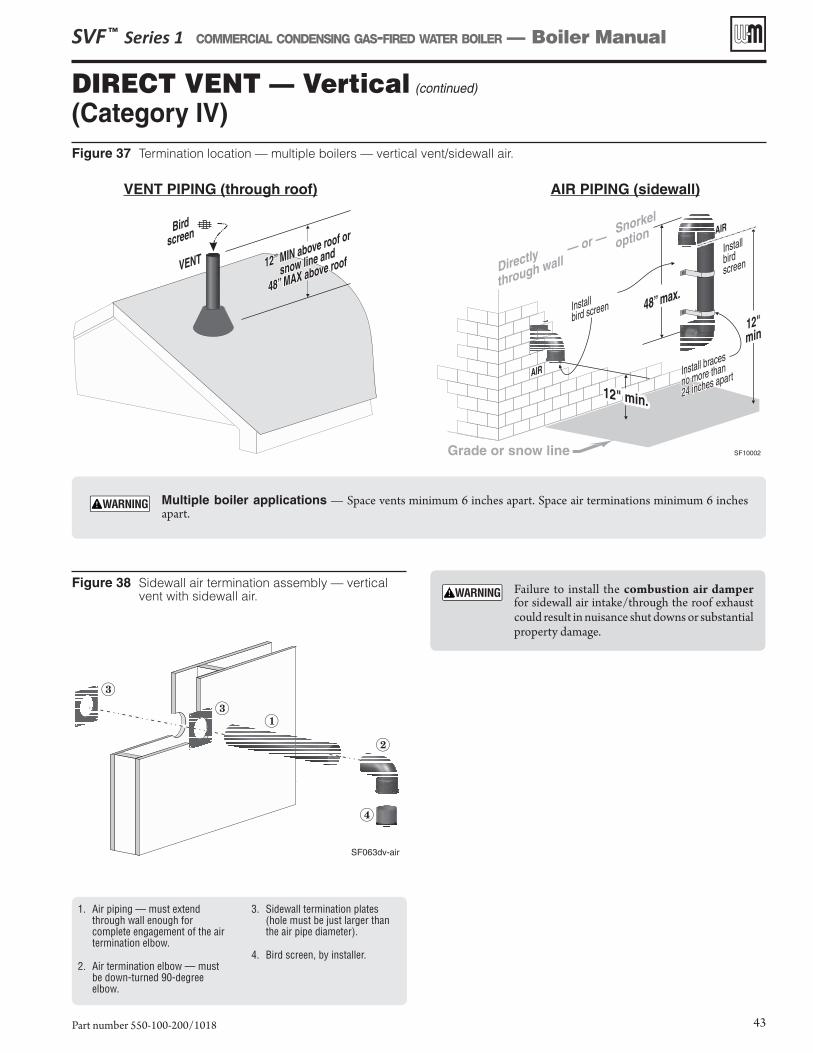
Figure 37 Termination location — multiple boilers — vertical vent/sidewall air.
VENT PIPING (through roof) AIR PIPING (sidewall)
Figure 38 Sidewall air termination assembly — vertical vent with sidewall air.
SVF ™ Series 1 COMMERCIAL CONDENSING GAS-FIRED WATER BOILER — Boiler Manual
Part number 550-100-200/1018 43
DIRECT VENT — Vertical (continued)
(Category IV)
1. Air piping — must extend through wall enough for complete engagement of the air termination elbow.
2. Air termination elbow — must be down-turned 90-degree elbow.
3. Sidewall termination plates (hole must be just larger than the air pipe diameter).
4. Bird screen, by installer.
Failure to install the combustion air damper for sidewall air intake/through the roof exhaust could result in nuisance shut downs or substantial property damage.
Multiple boiler applications — Space vents minimum 6 inches apart. Space air terminations minimum 6 inches apart.
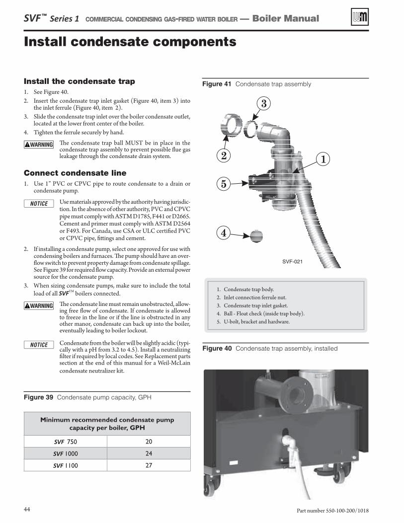
SVF ™ Series 1 COMMERCIAL CONDENSING GAS-FIRED WATER BOILER — Boiler Manual
Part number 550-100-200/101844
Minimum recommended condensate pump
capacity per boiler, GPH
SVF 750 20
SVF 1000 24
SVF 1100 27
Figure 39 Condensate pump capacity, GPH
Install the condensate trap1. See Figure 40.2. Insert the condensate trap inlet gasket (Figure 40, item 3) into
the inlet ferrule (Figure 40, item 2).3. Slide the condensate trap inlet over the boiler condensate outlet,
located at the lower front center of the boiler.4. Tighten the ferrule securely by hand.
The condensate trap ball MUST be in place in the condensate trap assembly to prevent possible flue gas leakage through the condensate drain system.
Connect condensate line1. Use 1” PVC or CPVC pipe to route condensate to a drain or
condensate pump.
Use materials approved by the authority having jurisdic-tion. In the absence of other authority, PVC and CPVC pipe must comply with ASTM D1785, F441 or D2665. Cement and primer must comply with ASTM D2564 or F493. For Canada, use CSA or ULC certified PVC or CPVC pipe, fittings and cement.
2. If installing a condensate pump, select one approved for use with condensing boilers and furnaces. The pump should have an over-flow switch to prevent property damage from condensate spillage. See Figure 39 for required flow capacity. Provide an external power source for the condensate pump.
3. When sizing condensate pumps, make sure to include the total load of all SVFTM boilers connected.
The condensate line must remain unobstructed, allow-ing free flow of condensate. If condensate is allowed to freeze in the line or if the line is obstructed in any other manor, condensate can back up into the boiler, eventually leading to boiler lockout.
Condensate from the boiler will be slightly acidic (typi-cally with a pH from 3.2 to 4.5). Install a neutralizing filter if required by local codes. See Replacement parts section at the end of this manual for a Weil-McLain condensate neutralizer kit.
Figure 40 Condensate trap assembly, installed
1. Condensate trap body.2. Inlet connection ferrule nut.3. Condensate trap inlet gasket.4. Ball - Float check (inside trap body).5. U-bolt, bracket and hardware.
Install condensate components
Figure 41 Condensate trap assembly
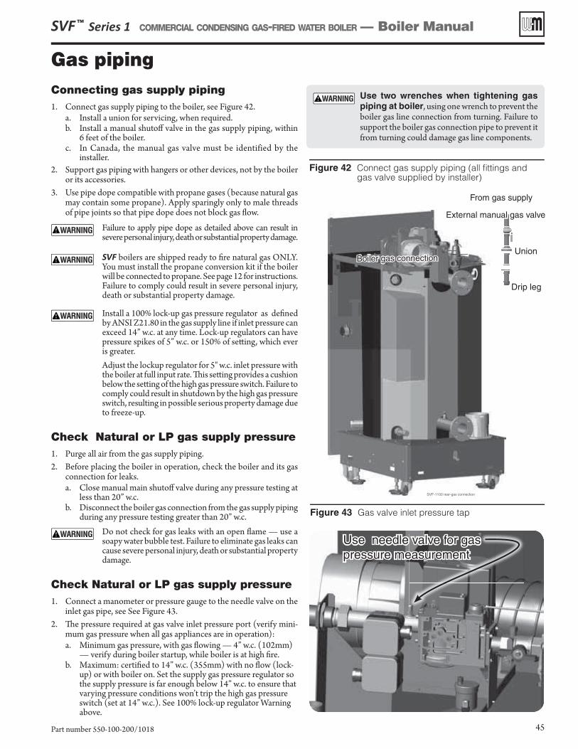
Connecting gas supply piping1. Connect gas supply piping to the boiler, see Figure 42 .
a. Install a union for servicing, when required.b. Install a manual shutoff valve in the gas supply piping, within
6 feet of the boiler.c. In Canada, the manual gas valve must be identified by the
installer.2. Support gas piping with hangers or other devices, not by the boiler
or its accessories.3. Use pipe dope compatible with propane gases (because natural gas
may contain some propane). Apply sparingly only to male threads of pipe joints so that pipe dope does not block gas fl ow.
Failure to apply pipe dope as detailed above can result in severe personal injury, death or substantial property damage.
SVF boilers are shipped ready to fi re natural gas ONLY. You must install the propane conversion kit if the boiler will be connected to propane. See page 12 for instructions. Failure to comply could result in severe personal injury, death or substantial property damage.
Install a 100% lock-up gas pressure regulator as defi ned by ANSI Z21.80 in the gas supply line if inlet pressure can exceed 14” w.c. at any time. Lock-up regulators can have pressure spikes of 5” w.c. or 150% of sett ing, which ever is greater.Adjust the lockup regulator for 5" w.c. inlet pressure with the boiler at full input rate. Th is sett ing provides a cushion below the sett ing of the high gas pressure switch. Failure to comply could result in shutdown by the high gas pressure switch, resulting in possible serious property damage due to freeze-up.
Check Natural or LP gas supply pressure1. Purge all air from the gas supply piping.2. Before placing the boiler in operation, check the boiler and its gas
connection for leaks.a. Close manual main shutoff valve during any pressure testing at
less than 20” w.c.b. Disconnect the boiler gas connection from the gas supply piping
during any pressure testing greater than 20” w.c. Do not check for gas leaks with an open fl ame — use a
soapy water bubble test. Failure to eliminate gas leaks can cause severe personal injury, death or substantial property damage.
Check Natural or LP gas supply pressure1. Connect a manometer or pressure gauge to the needle valve on the
inlet gas pipe, see See Figure 43 .2. Th e pressure required at gas valve inlet pressure port (verify mini-
mum gas pressure when all gas appliances are in operation):a. Minimum gas pressure, with gas fl owing — 4” w.c. (102mm)
— verify during boiler startup, while boiler is at high fi re. b. Maximum: certifi ed to 14” w.c. (355mm) with no fl ow (lock-
up) or with boiler on. Set the supply gas pressure regulator so the supply pressure is far enough below 14” w.c. to ensure that varying pressure conditions won’t trip the high gas pressure switch (set at 14” w.c.). See 100% lock-up regulator Warning above.
Figure 42 Connect gas supply piping (all fi ttings and gas valve supplied by installer)
External manual gas valve
Union
Drip leg
From gas supply
Boiler gas connection
Figure 43 Gas valve inlet pressure tap
SVF ™ Series 1 COMMERCIAL CONDENSING GAS-FIRED WATER BOILER — Boiler Manual
Part number 550-100-200/1018 45
Use two wrenches when tightening gas piping at boiler, using one wrench to prevent the boiler gas line connection from turning. Failure to support the boiler gas connection pipe to prevent it from turning could damage gas line components.
Gas piping
Use needle valve for gas pressure measurement
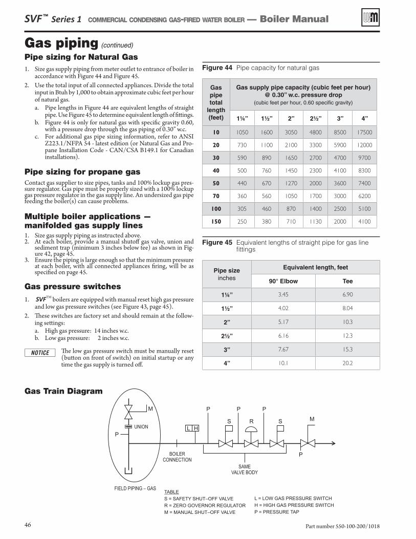
Figure 44 Pipe capacity for natural gas
Gaspipetotal
length(feet)
Gas supply pipe capacity (cubic feet per hour) @ 0.30” w.c. pressure drop
(cubic feet per hour, 0.60 specific gravity)
1¼” 1½” 2” 2½” 3” 4”
10 1050 1600 3050 4800 8500 17500
20 730 1100 2100 3300 5900 12000
30 590 890 1650 2700 4700 9700
40 500 760 1450 2300 4100 8300
50 440 670 1270 2000 3600 7400
70 360 560 1050 1700 3000 6200
100 305 460 870 1400 2500 5100
150 250 380 710 1130 2000 4100
Figure 45 Equivalent lengths of straight pipe for gas line fittings
Pipe sizeinches
Equivalent length, feet
90° Elbow Tee
1¼” 3.45 6.90
1½” 4.02 8.04
2” 5.17 10.3
2½” 6.16 12.3
3” 7.67 15.3
4” 10.1 20.2
Gas piping (continued)
Pipe sizing for Natural Gas1. Size gas supply piping from meter outlet to entrance of boiler in
accordance with Figure 44 and Figure 45. 2. Use the total input of all connected appliances. Divide the total
input in Btuh by 1,000 to obtain approximate cubic feet per hour of natural gas.a. Pipe lengths in Figure 44 are equivalent lengths of straight
pipe. Use Figure 45 to determine equivalent length of fittings.b. Figure 44 is only for natural gas with specific gravity 0.60,
with a pressure drop through the gas piping of 0.30” w.c.c. For additional gas pipe sizing information, refer to ANSI
Z223.1/NFPA 54 - latest edition (or Natural Gas and Pro-pane Installation Code - CAN/CSA B149.1 for Canadian installations).
Pipe sizing for propane gasContact gas supplier to size pipes, tanks and 100% lockup gas pres-sure regulator. Gas pipe must be properly sized with a 100% lockup gas pressure regulator in the gas supply line. An undersized gas pipe feeding the boiler(s) can cause problems.
Multiple boiler applications —manifolded gas supply lines1. Size gas supply piping as instructed above.2. At each boiler, provide a manual shutoff gas valve, union and
sediment trap (minimum 3 inches below tee) as shown in Fig-ure 42, page 45.
3. Ensure the piping is large enough so that the minimum pressure at each boiler, with all connected appliances firing, will be as specified on page 45.
Gas pressure switches
1. SVFTM boilers are equipped with manual reset high gas pressure and low gas pressure switches (see Figure 43, page 45).
2. These switches are factory set and should remain at the follow-ing settings:a. High gas pressure: 14 inches w.c.b. Low gas pressure: 2 inches w.c.
The low gas pressure switch must be manually reset (button on front of switch) on initial startup or any time the gas supply is turned off.
Gas Train Diagram
SVF ™ Series 1 COMMERCIAL CONDENSING GAS-FIRED WATER BOILER — Boiler Manual
Part number 550-100-200/101846
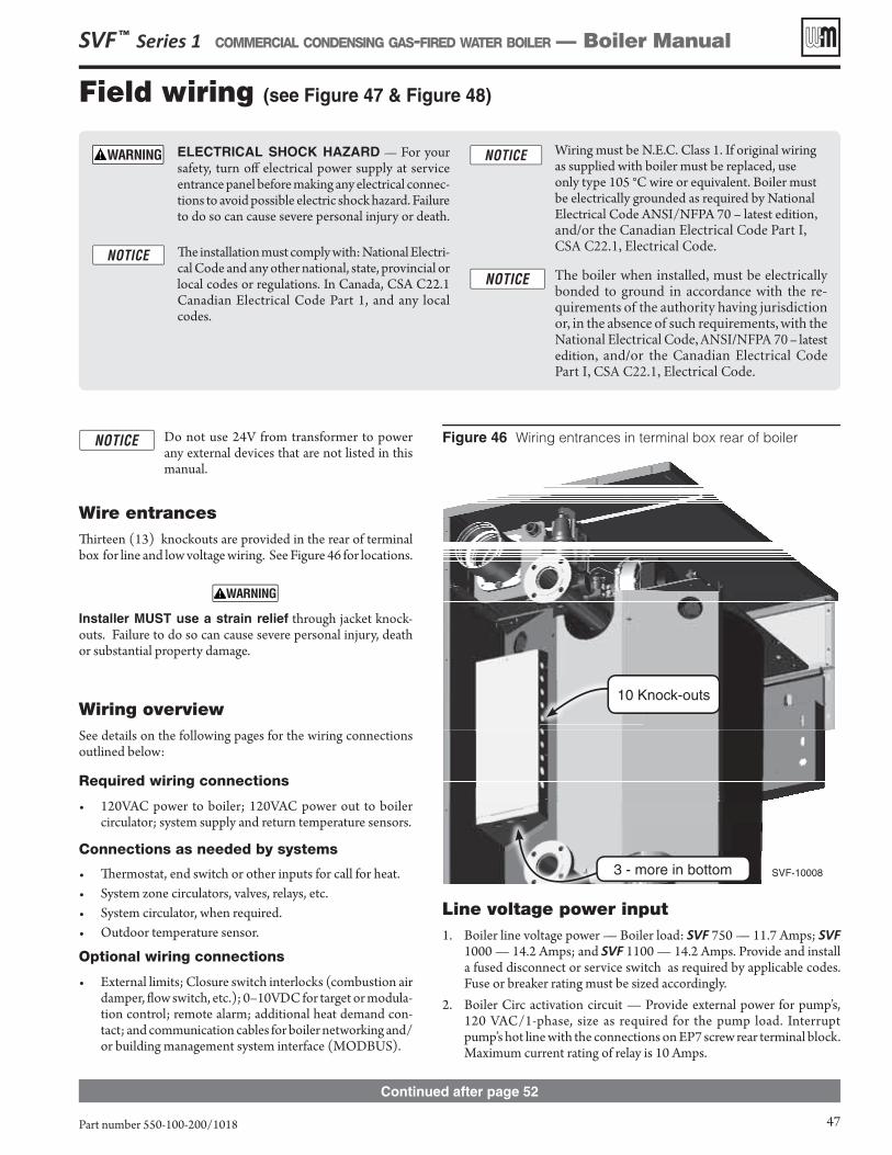
Continued after page 52
3 - more in bottom
10 Knock-outs
SVF ™ Series 1 COMMERCIAL CONDENSING GAS-FIRED WATER BOILER — Boiler Manual
Part number 550-100-200/1018 47
Do not use 24V from transformer to power any external devices that are not listed in this manual.
Wire entrancesTh irteen (13) knockouts are provided in the rear of terminal box for line and low voltage wiring. See Figure 46 for locations.
Installer MUST use a strain relief through jacket knock-outs. Failure to do so can cause severe personal injury, death or substantial property damage.
Wiring overviewSee details on the following pages for the wiring connections outlined below:
Required wiring connections
• 120VAC power to boiler; 120VAC power out to boiler circulator; system supply and return temperature sensors.
Connections as needed by systems
• Th ermostat, end switch or other inputs for call for heat.• System zone circulators, valves, relays, etc.• System circulator, when required.• Outdoor temperature sensor.
Optional wiring connections
• External limits; Closure switch interlocks (combustion air damper, fl ow switch, etc.); 0–10VDC for target or modula-tion control; remote alarm; additional heat demand con-tact; and communication cables for boiler networking and/or building management system interface (MODBUS).
Figure 46 Wiring entrances in terminal box rear of boiler
ELECTRICAL SHOCK HAZARD — For your safety, turn off electrical power supply at service entrance panel before making any electrical connec-tions to avoid possible electric shock hazard. Failure to do so can cause severe personal injury or death.
Th e installation must comply with: National Electri-cal Code and any other national, state, provincial or local codes or regulations. In Canada, CSA C22.1 Canadian Electrical Code Part 1, and any local codes.
Wiring must be N.E.C. Class 1. If original wiring as supplied with boiler must be replaced, use only type 105 °C wire or equivalent. Boiler must be electrically grounded as required by National Electrical Code ANSI/NFPA 70 – latest edition, and/or the Canadian Electrical Code Part I, CSA C22.1, Electrical Code.
The boiler when installed, must be electrically bonded to ground in accordance with the re-quirements of the authority having jurisdiction or, in the absence of such requirements, with the National Electrical Code, ANSI/NFPA 70 – latest edition, and/or the Canadian Electrical Code Part I, CSA C22.1, Electrical Code.
Line voltage power input1. Boiler line voltage power — Boiler load: SVF 750 — 11.7 Amps; SVF
1000 — 14.2 Amps; and SVF 1100 — 14.2 Amps. Provide and install a fused disconnect or service switch as required by applicable codes. Fuse or breaker rating must be sized accordingly.
2. Boiler Circ activation circuit — Provide external power for pump’s, 120 VAC/1-phase, size as required for the pump load. Interrupt pump’s hot line with the connections on EP7 screw rear terminal block. Maximum current rating of relay is 10 Amps.
Field wiring (see Figure 47 & Figure 48 )
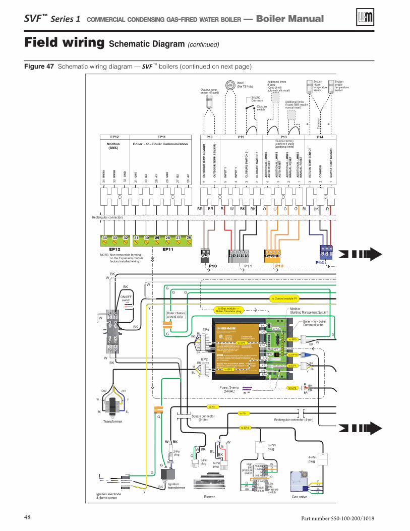
Figure 47 Schematic wiring diagram — SVF TM boilers (continued on next page)
SVF ™ Series 1 COMMERCIAL CONDENSING GAS-FIRED WATER BOILER — Boiler Manual
Part number 550-100-200/101848
Field wiring Schematic Diagram (continued)
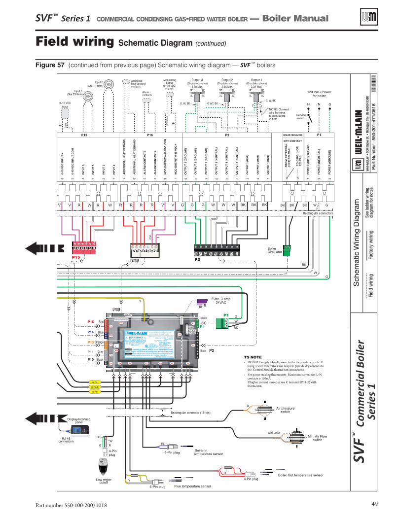
Figure 57 (continued from previous page) Schematic wiring diagram — SVF TM boilers
SVF ™ Series 1 COMMERCIAL CONDENSING GAS-FIRED WATER BOILER — Boiler Manual
Part number 550-100-200/1018 49
Field wiring Schematic Diagram (continued)
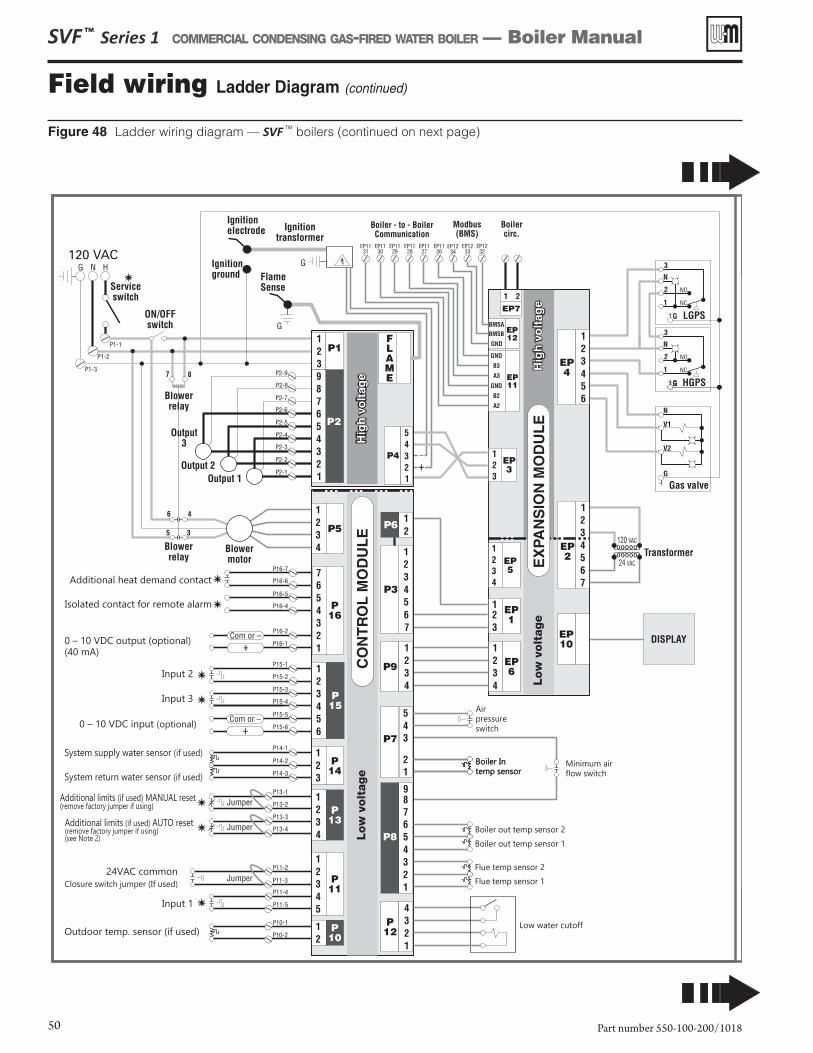
Figure 48 Ladder wiring diagram — SVF TM boilers (continued on next page)
SVF ™ Series 1 COMMERCIAL CONDENSING GAS-FIRED WATER BOILER — Boiler Manual
Part number 550-100-200/101850
Field wiring Ladder Diagram (continued)
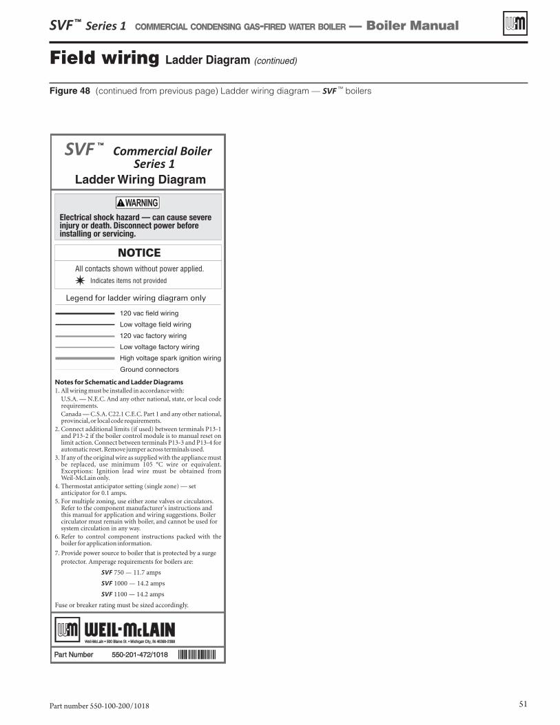
Figure 48 (continued from previous page) Ladder wiring diagram — SVF TM boilers
SVF ™ Series 1 COMMERCIAL CONDENSING GAS-FIRED WATER BOILER — Boiler Manual
Part number 550-100-200/1018 51
Field wiring Ladder Diagram (continued)
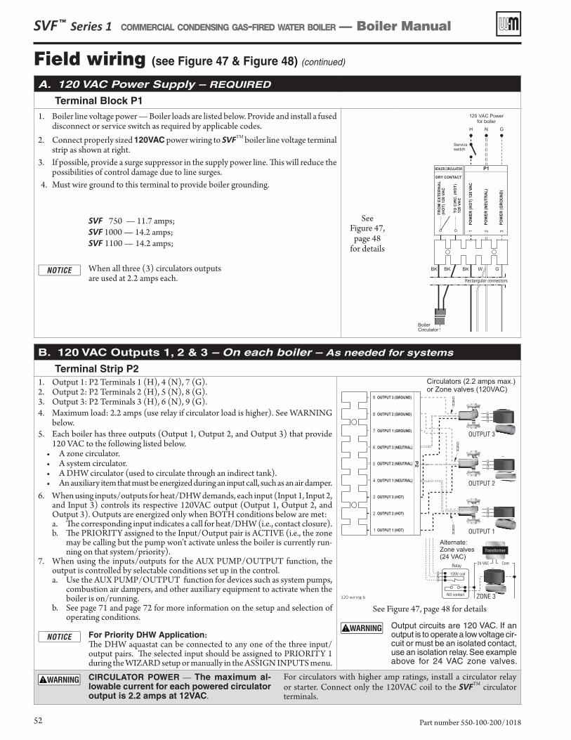
A. 120 VAC Power Supply – REQUIRED
Terminal Block P11. Boiler line voltage power — Boiler loads are listed below. Provide and install a fused
disconnect or service switch as required by applicable codes. 2. Connect properly sized 120VAC power wiring to SVFTM boiler line voltage terminal
strip as shown at right.3. If possible, provide a surge suppressor in the supply power line. This will reduce the
possibilities of control damage due to line surges.4. Must wire ground to this terminal to provide boiler grounding.
SVF 750 — 11.7 amps; SVF 1000 — 14.2 amps; SVF 1100 — 14.2 amps;
When all three (3) circulators outputs are used at 2.2 amps each.
See Figure 47,
page 48 for details
B. 120 VAC Outputs 1, 2 & 3 – On each boiler – As needed for systems
Terminal Strip P2 1. Output 1: P2 Terminals 1 (H), 4 (N), 7 (G).2. Output 2: P2 Terminals 2 (H), 5 (N), 8 (G).3. Output 3: P2 Terminals 3 (H), 6 (N), 9 (G).4. Maximum load: 2.2 amps (use relay if circulator load is higher). See WARNING
below.5. Each boiler has three outputs (Output 1, Output 2, and Output 3) that provide
120 VAC to the following listed below. • A zone circulator.• A system circulator. • A DHW circulator (used to circulate through an indirect tank). • An auxiliary item that must be energized during an input call, such as an air damper.
6. When using inputs/outputs for heat/DHW demands, each input (Input 1, Input 2, and Input 3) controls its respective 120VAC output (Output 1, Output 2, and Output 3). Outputs are energized only when BOTH conditions below are met:a. The corresponding input indicates a call for heat/DHW (i.e., contact closure).b. The PRIORITY assigned to the Input/Output pair is ACTIVE (i.e., the zone
may be calling but the pump won’t activate unless the boiler is currently run-ning on that system/priority).
7. When using the inputs/outputs for the AUX PUMP/OUTPUT function, the output is controlled by selectable conditions set up in the control. a. Use the AUX PUMP/OUTPUT function for devices such as system pumps,
combustion air dampers, and other auxiliary equipment to activate when the boiler is on/running.
b. See page 71 and page 72 for more information on the setup and selection of operating conditions.
For Priority DHW Application: The DHW aquastat can be connected to any one of the three input/
output pairs. The selected input should be assigned to PRIORITY 1 during the WIZARD setup or manually in the ASSIGN INPUTS menu.
See Figure 47, page 48 for details
Output circuits are 120 VAC. If an output is to operate a low voltage cir-cuit or must be an isolated contact, use an isolation relay. See example above for 24 VAC zone valves.
CIRCULATOR POWER — The maximum al-lowable current for each powered circulator output is 2.2 amps at 12VAC.
For circulators with higher amp ratings, install a circulator relay or starter. Connect only the 120VAC coil to the SVFTM circulator terminals.
SVF ™ Series 1 COMMERCIAL CONDENSING GAS-FIRED WATER BOILER — Boiler Manual
Part number 550-100-200/101852
Field wiring (see Figure 47 & Figure 48) (continued)
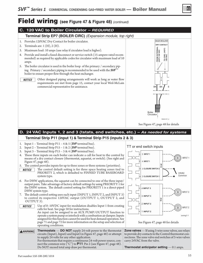
C. 120 VAC to Boiler Circulator – REQUIRED
Terminal Strip EP7 (BOILER CIRC) (Expansion module, top right)1. Provides 120VAC Dry Contact for boiler circulator.2. Terminals are: 1 (H), 2 (H).3. Maximum load: 10 amps (use relay if circulator load is higher). 4. Provide and install a fused disconnect or service switch (15-ampere rated recom-
mended) as required by applicable codes for circulator with maximum load of 10 amps.
5. The boiler circulator is used in the boiler loop of the primary / secondary pip-ing. Primary / secondary piping is recommended to be used with the SVFTM boiler to ensure proper flow through the heat exchanger.
Other designed piping arrangements will work as long as water flow requirements are met from page 15, contact your local Weil-McLain commercial representative for assistance.
See Figure 47, page 48 for details
D. 24 VAC Inputs 1, 2 and 3 (tstats, end switches, etc.) – As needed for systems
Terminal Strip P11 (input 1) & Terminal Strip P15 (inputs 2 & 3)
1. Input 1 – Terminal Strip P11 – 4 & 5 (SVF terminal bus).2. Input 2 – Terminal Strip P15 – 1 & 2 (SVF terminal bus).3. Input 3 – Terminal Strip P15 – 3 & 4 (SVF terminal bus).4. These three inputs on each boiler can indicate a call for heat to the control by
means of a dry contact closure (thermostat, aquastat, or switch). (See right and Figure 47, page 48).
5. The control provides inputs for up to three zones or three systems (priorities). The control default setting is for three space heating zones tied to
PRIORITY 2, which is defaulted to FINNED TUBE BASEBOARD system type.
6. For DHW applications, the aquastat can be connected to one of the three input/output pairs. Take advantage of factory default settings by using PRIORITY 1 for the DHW system. The default control setting for PRIORITY 1 is a direct-piped DHW system type.
7. The default control setting uses each input (INPUT 1, INPUT 2, and INPUT 3) to control its respective 120VAC output (OUTPUT 1, OUTPUT 2, and OUTPUT 3).
Use of 0–10VDC input for modulation disables Input 1 from creating calls for heat. See page 58 for instructions.
An input can be assigned to an AUX PUMP/OUTPUT function to operate a system pump or interlock with a combustion air damper. Inputs assigned for this function cannot be used for heat demand operation. See page 71 and page 72 for more information on the setup and selection of operating conditions.
See Figure 47, page 48 for details
Thermostats — DO NOT supply 24-volt power to the thermostat circuits (Input1, Input2 and Input3 in Figure 47, page 48) or attempt to supply 24 volts for any other application.
For thermostats that require a continuous 24-volt power source, con-nect the common wire (“C”) to P11 Pin 2 (see Figure 47, page 48).Do NOT exceed total amp draw per thermostat.
Zone valves — If using 3-wire zone valves, use relays to provide dry contacts to the Control thermostat con-nections. The zone valve end switches of 3-wire valves carry 24VAC from the valve.
Thermostat anticipator setting — 0.1 amps.
SVF ™ Series 1 COMMERCIAL CONDENSING GAS-FIRED WATER BOILER — Boiler Manual
Part number 550-100-200/1018 53
Field wiring (see Figure 47 & Figure 48) (continued)
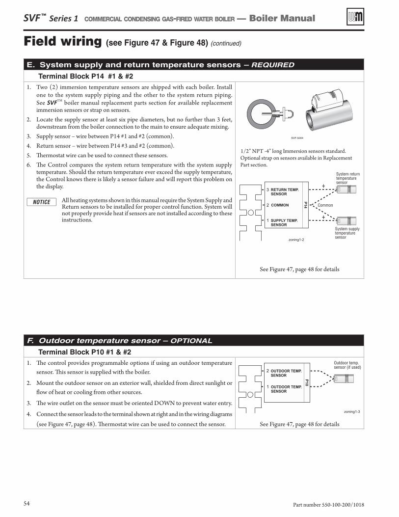
E. System supply and return temperature sensors – REQUIRED
Terminal Block P14 #1 & #21. Two (2) immersion temperature sensors are shipped with each boiler. Install
one to the system supply piping and the other to the system return piping. See SVFTM boiler manual replacement parts section for available replacement immersion sensors or strap on sensors.
2. Locate the supply sensor at least six pipe diameters, but no further than 3 feet, downstream from the boiler connection to the main to ensure adequate mixing.
3. Supply sensor – wire between P14 #1 and #2 (common).4. Return sensor – wire between P14 #3 and #2 (common).5. Thermostat wire can be used to connect these sensors.6. The Control compares the system return temperature with the system supply
temperature. Should the return temperature ever exceed the supply temperature, the Control knows there is likely a sensor failure and will report this problem on the display.
All heating systems shown in this manual require the System Supply and Return sensors to be installed for proper control function. System will not properly provide heat if sensors are not installed according to these instructions.
1/2” NPT -4” long Immersion sensors standard. Optional strap on sensors available in Replacement Part section.
See Figure 47, page 48 for details
F. Outdoor temperature sensor – OPTIONAL
Terminal Block P10 #1 & #21. The control provides programmable options if using an outdoor temperature
sensor. This sensor is supplied with the boiler.
2. Mount the outdoor sensor on an exterior wall, shielded from direct sunlight or flow of heat or cooling from other sources.
3. The wire outlet on the sensor must be oriented DOWN to prevent water entry.
4. Connect the sensor leads to the terminal shown at right and in the wiring diagrams (see Figure 47, page 48). Thermostat wire can be used to connect the sensor. See Figure 47, page 48 for details
SVF ™ Series 1 COMMERCIAL CONDENSING GAS-FIRED WATER BOILER — Boiler Manual
Part number 550-100-200/101854
Field wiring (see Figure 47 & Figure 48) (continued)
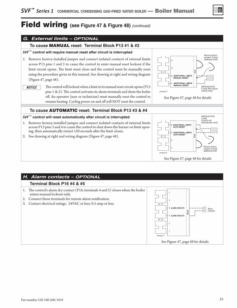
G. External limits – OPTIONAL
To cause MANUAL reset: Terminal Block P13 #1 & #2
SVFTM control will require manual reset after circuit is interrupted
1. Remove factory-installed jumper and connect isolated contacts of external limits across P13 pins 1 and 2 to cause the control to enter manual reset lockout if the limit circuit opens. The limit must close and the control must be manually reset using the procedure given in this manual. See drawing at right and wiring diagram (Figure 47, page 48).
The control will lockout when a limit in its manual reset circuit opens (P13 pins 1 & 2). The control activates its alarm terminals and shuts the boiler off. An operator (user or technician) must manually reset the control to resume heating. Cycling power on and off will NOT reset the control.
See Figure 47, page 48 for details
To cause AUTOMATIC reset: Terminal Block P13 #3 & #4
SVFTM control will reset automatically after circuit is interrupted
1. Remove factory-installed jumper and connect isolated contacts of external limits across P13 pins 3 and 4 to cause the control to shut down the burner on limit open-ing, then automatically restart 150 seconds after the limit closes.
2. See drawing at right and wiring diagram (Figure 47, page 48).
See Figure 47, page 48 for details
H. Alarm contacts – OPTIONAL
Terminal Block P16 #4 & #51. The control’s alarm dry contact (P16, terminals 4 and 5) closes when the boiler
enters manual lockout only.2. Connect these terminals for remote alarm notification.3. Contact electrical ratings: 24VAC or less; 0.5 amp or less.
See Figure 47, page 48 for details
SVF ™ Series 1 COMMERCIAL CONDENSING GAS-FIRED WATER BOILER — Boiler Manual
Part number 550-100-200/1018 55
Field wiring (see Figure 47 & Figure 48) (continued)
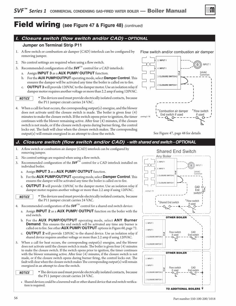
I. Closure switch (flow switch and/or CAD) – OPTIONAL
Jumper on Terminal Strip P11 1. A flow switch or combustion air damper (CAD) interlock can be configured by
removing jumper.
2. No control settings are required when using a flow switch.3. Recommended configuration of the SVFTM control for a CAD interlock:
a. Assign INPUT 3 as a AUX PUMP/ OUTPUT function. b. For the AUX PUMP/OUTPUT operating mode, select Damper Control. This
ensures the damper will be activated any time the boiler is called on to fire.c. OUTPUT 3 will provide 120VAC to the damper motor. Use an isolation relay if
damper motor requires another voltage or more than 2.2 amp if using 120VAC.
* The devices used must provide electrically isolated contacts, because the P11 jumper circuit carries 24 VAC.
4. When a call for heat occurs, the corresponding output(s) energize, and the blower does not activate until the closure switch is made. The boiler is given four (4) minutes to make the closure switch. If the switch opens prior to ignition, the timer continues with the blower remaining active. After four (4) minutes, if the closure switch is not made, or if the closure switch opens during burner firing, the control locks out. The fault will clear when the closure switch makes. The corresponding output(s) will remain energized in an attempt to close the switch. See Figure 47, page 48 for details
J. Closure switch (flow switch and/or CAD) - with shared end switch - OPTIONAL
1. A flow switch or combustion air damper (CAD) interlock can be configured by removing jumper.
2. No control settings are required when using a flow switch.3. Recommended configuration of the SVFTM control for a CAD interlock installed on
individual boiler.a. Assign INPUT 3 as a AUX PUMP/ OUTPUT function. b. For the AUX PUMP/OUTPUT operating mode, select Damper Control. This
ensures the damper will be activated any time the boiler is called on to fire.c. OUTPUT 3 will provide 120VAC to the damper motor. Use an isolation relay if
damper motor requires another voltage or more than 2.2 amp if using 120VAC.
* The devices used must provide electrically isolated contacts, because the P11 jumper circuit carries 24 VAC.
4. Recommended configuration of the SVFTM control for a shared end switch device:a. Assign INPUT 2 as a AUX PUMP/ OUTPUT function on the boiler with the
end switch. b. For the AUX PUMP/OUTPUT operating mode, select ANY Burner
Demand. This ensures the end switch will be activated any time any burner is called on to fire. See other AUX PUMP/ OUTPUT options in Figure 60, page 72.
c. OUTPUT 2 will provide 120VAC to the shared device. Use an isolation relay if shared device requires another voltage or more than 2.2 amp if using 120VAC.
5. When a call for heat occurs, the corresponding output(s) energize, and the blower does not activate until the closure switch is made. The boiler is given four (4) minutes to make the closure switch. If the switch opens prior to ignition, the timer continues with the blower remaining active. After four (4) minutes, if the closure switch is not made, or if the closure switch opens during burner firing, the control locks out. The fault will clear when the closure switch makes The corresponding output(s) will remain energized in an attempt to close the switch.
* The devices used must provide electrically isolated contacts, because the P11 jumper circuit carries 24 VAC.
• Shared devices could be a louvered wall or other shared device that end switch verifica-tion is required.
SVF ™ Series 1 COMMERCIAL CONDENSING GAS-FIRED WATER BOILER — Boiler Manual
Part number 550-100-200/101856
Field wiring (see Figure 47 & Figure 48) (continued)
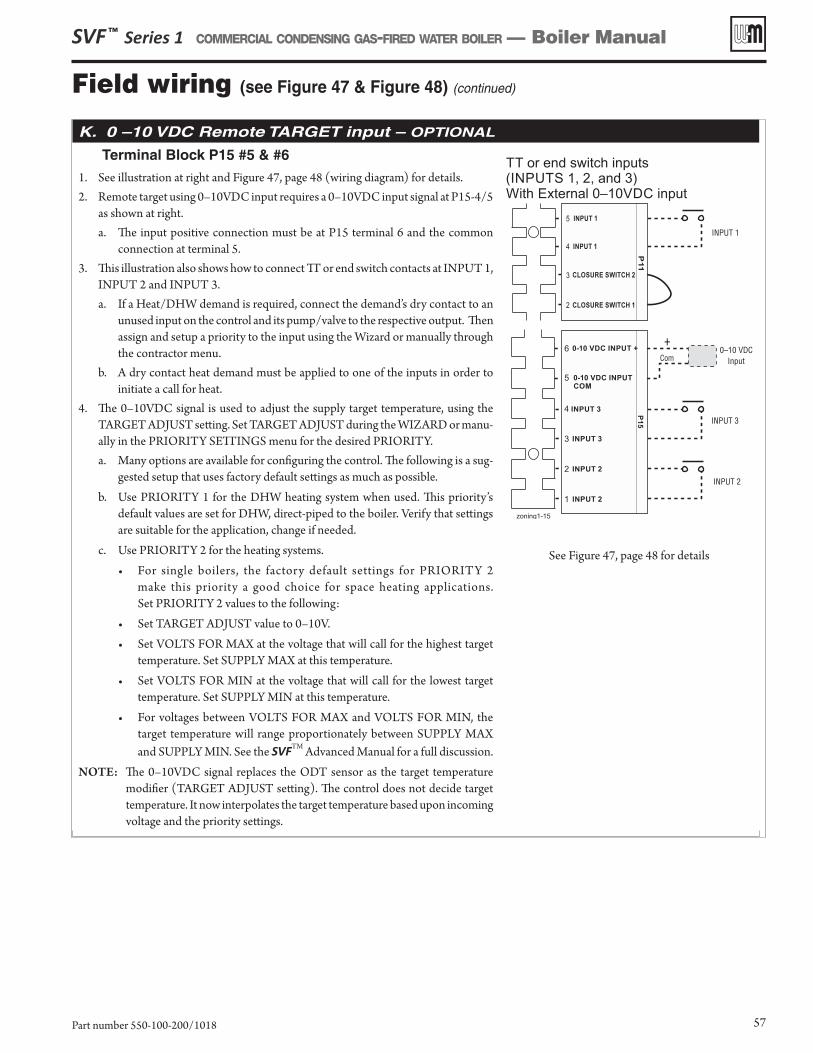
K. 0 –10 VDC Remote TARGET input – OPTIONAL
Terminal Block P15 #5 & #6 1. See illustration at right and Figure 47, page 48 (wiring diagram) for details. 2. Remote target using 0–10VDC input requires a 0–10VDC input signal at P15-4/5
as shown at right. a. The input positive connection must be at P15 terminal 6 and the common
connection at terminal 5.3. This illustration also shows how to connect TT or end switch contacts at INPUT 1,
INPUT 2 and INPUT 3. a. If a Heat/DHW demand is required, connect the demand’s dry contact to an
unused input on the control and its pump/valve to the respective output. Then assign and setup a priority to the input using the Wizard or manually through the contractor menu.
b. A dry contact heat demand must be applied to one of the inputs in order to initiate a call for heat.
4. The 0–10VDC signal is used to adjust the supply target temperature, using the TARGET ADJUST setting. Set TARGET ADJUST during the WIZARD or manu-ally in the PRIORITY SETTINGS menu for the desired PRIORITY.a. Many options are available for configuring the control. The following is a sug-
gested setup that uses factory default settings as much as possible.b. Use PRIORITY 1 for the DHW heating system when used. This priority’s
default values are set for DHW, direct-piped to the boiler. Verify that settings are suitable for the application, change if needed.
c. Use PRIORITY 2 for the heating systems.• For single boilers, the factory default settings for PRIORITY 2
make this priority a good choice for space heating applications. Set PRIORITY 2 values to the following:
• Set TARGET ADJUST value to 0–10V.• Set VOLTS FOR MAX at the voltage that will call for the highest target
temperature. Set SUPPLY MAX at this temperature.• Set VOLTS FOR MIN at the voltage that will call for the lowest target
temperature. Set SUPPLY MIN at this temperature.• For voltages between VOLTS FOR MAX and VOLTS FOR MIN, the
target temperature will range proportionately between SUPPLY MAX and SUPPLY MIN. See the SVFTM Advanced Manual for a full discussion.
NOTE: The 0–10VDC signal replaces the ODT sensor as the target temperature modifier (TARGET ADJUST setting). The control does not decide target temperature. It now interpolates the target temperature based upon incoming voltage and the priority settings.
See Figure 47, page 48 for details
SVF ™ Series 1 COMMERCIAL CONDENSING GAS-FIRED WATER BOILER — Boiler Manual
Part number 550-100-200/1018 57
Field wiring (see Figure 47 & Figure 48) (continued)
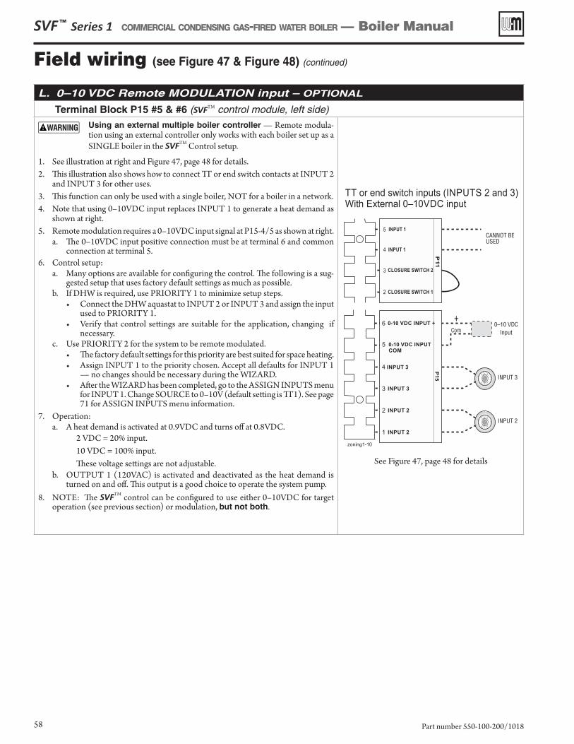
L. 0–10 VDC Remote MODULATION input – OPTIONAL
Terminal Block P15 #5 & #6 (SVFTM control module, left side)
Using an external multiple boiler controller — Remote modula-tion using an external controller only works with each boiler set up as a SINGLE boiler in the SVFTM Control setup.
1. See illustration at right and Figure 47, page 48 for details.2. This illustration also shows how to connect TT or end switch contacts at INPUT 2
and INPUT 3 for other uses. 3. This function can only be used with a single boiler, NOT for a boiler in a network.4. Note that using 0–10VDC input replaces INPUT 1 to generate a heat demand as
shown at right. 5. Remote modulation requires a 0–10VDC input signal at P15-4/5 as shown at right.
a. The 0–10VDC input positive connection must be at terminal 6 and common connection at terminal 5.
6. Control setup: a. Many options are available for configuring the control. The following is a sug-
gested setup that uses factory default settings as much as possible.b. If DHW is required, use PRIORITY 1 to minimize setup steps.
• Connect the DHW aquastat to INPUT 2 or INPUT 3 and assign the input used to PRIORITY 1.
• Verify that control settings are suitable for the application, changing if necessary.
c. Use PRIORITY 2 for the system to be remote modulated. • The factory default settings for this priority are best suited for space heating. • Assign INPUT 1 to the priority chosen. Accept all defaults for INPUT 1
— no changes should be necessary during the WIZARD.• After the WIZARD has been completed, go to the ASSIGN INPUTS menu
for INPUT 1. Change SOURCE to 0–10V (default setting is TT1). See page 71 for ASSIGN INPUTS menu information.
7. Operation:a. A heat demand is activated at 0.9VDC and turns off at 0.8VDC.
2 VDC = 20% input. 10 VDC = 100% input. These voltage settings are not adjustable.
b. OUTPUT 1 (120VAC) is activated and deactivated as the heat demand is turned on and off. This output is a good choice to operate the system pump.
8. NOTE: The SVFTM control can be configured to use either 0–10VDC for target operation (see previous section) or modulation, but not both.
TT INPUTS 2 and 3)or end switch inputs (With External 0–10VDC input
zoning1-10
INPUT 2
INPUT 3
80 6070
80
70
60
80 6070
80
70
60
1 INPUT 2
2 INPUT 2
3 INPUT 3
4
0-10 VDC INPUT +
P15
CANNOT BEUSED
5
4
3
2
INPUT 1
INPUT 1
CLOSURE SWITCH 2
CLOSURE SWITCH 1
P11
0–10 VDCInput
+
Com
5 0-10 VDC INPUT
COM
6
INPUT 3
See Figure 47, page 48 for details
SVF ™ Series 1 COMMERCIAL CONDENSING GAS-FIRED WATER BOILER — Boiler Manual
Part number 550-100-200/101858
Field wiring (see Figure 47 & Figure 48) (continued)
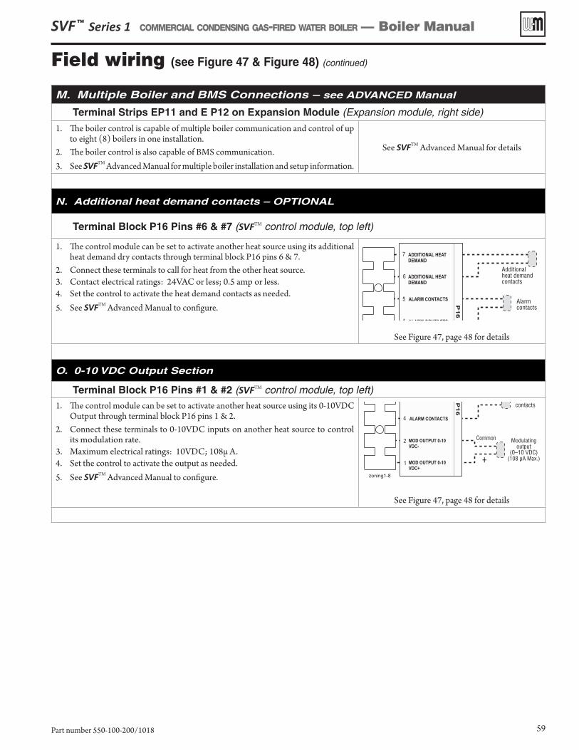
M. Multiple Boiler and BMS Connections – see ADVANCED Manual
Terminal Strips EP11 and E P12 on Expansion Module (Expansion module, right side)
1. The boiler control is capable of multiple boiler communication and control of up to eight (8) boilers in one installation.
2. The boiler control is also capable of BMS communication.3. See SVFTM Advanced Manual for multiple boiler installation and setup information.
See SVFTM Advanced Manual for details
N. Additional heat demand contacts – OPTIONAL
Terminal Block P16 Pins #6 & #7 (SVFTM control module, top left)
1. The control module can be set to activate another heat source using its additional heat demand dry contacts through terminal block P16 pins 6 & 7.
2. Connect these terminals to call for heat from the other heat source.3. Contact electrical ratings: 24VAC or less; 0.5 amp or less.4. Set the control to activate the heat demand contacts as needed.5. See SVFTM Advanced Manual to configure.
See Figure 47, page 48 for details
O. 0-10 VDC Output Section
Terminal Block P16 Pins #1 & #2 (SVFTM control module, top left)1. The control module can be set to activate another heat source using its 0-10VDC
Output through terminal block P16 pins 1 & 2.2. Connect these terminals to 0-10VDC inputs on another heat source to control
its modulation rate.3. Maximum electrical ratings: 10VDC; 108μ A. 4. Set the control to activate the output as needed.5. See SVFTM Advanced Manual to configure.
See Figure 47, page 48 for details
SVF ™ Series 1 COMMERCIAL CONDENSING GAS-FIRED WATER BOILER — Boiler Manual
Part number 550-100-200/1018 59
Field wiring (see Figure 47 & Figure 48) (continued)
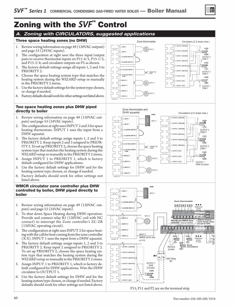
SVF ™ Series 1 COMMERCIAL CONDENSING GAS-FIRED WATER BOILER — Boiler Manual
Part number 550-100-200/101860
Zoning with the SVFTM
ControlA. Zoning with CIRCULATORS, suggested applications
Three space heating zones (no DHW)
1. Review wiring information on page 49 (120VAC outputs) and page 53 (24VAC inputs).
2. The configuration at right uses the three input/output pairs to receive thermostat inputs on P11-4/5, P15-1/2, and P15-3/4; and circulator outputs on P2 as shown.
3. The factory default settings assign all inputs 1, 2 and 3 to PRIORITY 2.
4. Choose the space heating system type that matches the heating system during the WIZARD setup or manually in the PRIORITY 2 menu.
5. Use the factory default settings for the system type chosen, or change if needed.
6. Factory defaults should work for other settings not listed above.
Two space heating zones plus DHW piped directly to boiler
1. Review wiring information on page 49 (120VAC out-puts) and page 53 (24VAC inputs).
2. The configuration at right uses INPUT 2 and 3 for space heating thermostats. INPUT 1 uses the input from a DHW aquastat.
3. The factory default settings assign inputs 1, 2 and 3 to PRIORITY 2. Keep inputs 2 and 3 assigned to PRIOR-ITY 2. To set up PRIORITY 2, choose the space heating system type that matches the heating system during the WIZARD setup or manually in the PRIORITY 2 menu.
4. Assign INPUT 1 to PRIORITY 1, which is factory default configured for DHW applications.
5. Use the factory default settings for DHW and for the heating system type chosen, or change if needed.
6. Factory defaults should work for other settings not listed above.
WMCR circulator zone controller plus DHW controlled by boiler, DHW piped directly to boiler
1. Review wiring information on page 49 (120VAC out-puts) and page 53 (24VAC inputs).
2. To shut down Space Heating during DHW operation: Provide and connect relay R1 (120VAC coil with NC contact) to interrupt the Zone controller’s ZC-ZR (120VAC operating circuit).
3. The configuration at right uses INPUT 2 for space heat-ing with the call for heat coming from the zone controller (X-X). INPUT 1 uses the input from a DHW aquastat.
4. The factory default settings assign inputs 1, 2 and 3 to PRIORITY 2. Keep input 2 assigned to PRIORITY 2. To set up PRIORITY 2, choose the space heating sys-tem type that matches the heating system during the WIZARD setup or manually in the PRIORITY 2 menu.
5. Assign INPUT 1 to PRIORITY 1, which is factory de-fault configured for DHW applications. Wire the DHW circulator to OUTPUT 1.
6. Use the factory default settings for DHW and for the heating system type chosen, or change if needed. Factory defaults should work for other settings not listed above.
P15, P11 and P2 are on the terminal strip
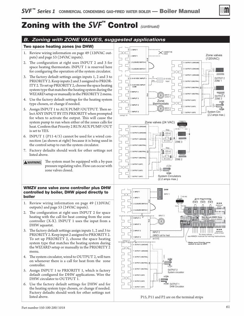
SVF ™ Series 1 COMMERCIAL CONDENSING GAS-FIRED WATER BOILER — Boiler Manual
Part number 550-100-200/1018 61
Zoning with the SVFTM
Control (continued)
B. Zoning with ZONE VALVES, suggested applications
Two space heating zones (no DHW)
1. Review wiring information on page 49 (120VAC out-puts) and page 53 (24VAC inputs).
2. The configuration at right uses INPUT 2 and 3 for space heating thermostats. INPUT 1 is reserved here for configuring the operation of the system circulator.
3. The factory default settings assign inputs 1, 2 and 3 to PRIORITY 2. Keep inputs 2 and 3 assigned to PRIOR-ITY 2. To set up PRIORITY 2, choose the space heating system type that matches the heating system during the WIZARD setup or manually in the PRIORITY 2 menu.
4. Use the factory default settings for the heating system type chosen, or change if needed.
5. Assign INPUT 1 to AUX PUMP/OUTPUT. Then se-lect ANY INPUT BY ITS PRIORITY when prompted for when to activate the output. This will cause the system pump to run when either of the zones calls for heat. Confirm that Priority 2 RUN AUX PUMP/OUT is set to YES.
6. INPUT 1 (P11-4/5) cannot be used for a wired con-nection (as shown at right) because it is being used in the control setup to run the system circulator.
7. Factory defaults should work for other settings not listed above.
The system must be equipped with a by-pass pressure regulating valve. Flow can occur with zone valves closed.
WMZV zone valve zone controller plus DHW controlled by boiler, DHW piped directly to boiler
P15, P11 and P2 are on the terminal strips
1. Review wiring information on page 49 (120VAC outputs) and page 53 (24VAC inputs).
2. The configuration at right uses INPUT 2 for space heating with the call for heat coming from the zone controller (X-X). INPUT 1 uses the input from a DHW aquastat.
3. The factory default settings assign inputs 1, 2 and 3 to PRIORITY 2. Keep input 2 assigned to PRIORITY 2. To set up PRIORITY 2, choose the space heating system type that matches the heating system during the WIZARD setup or manually in the PRIORITY 2 menu.
4. The system circulator, wired to OUTPUT 2, will turn on whenever there is a call for heat from the zone controller.
5. Assign INPUT 1 to PRIORITY 1, which is factory default configured for DHW applications. Wire the DHW circulator to OUTPUT 1.
6. Use the factory default settings for DHW and for the heating system type chosen, or change if needed. Factory defaults should work for other settings not listed above.
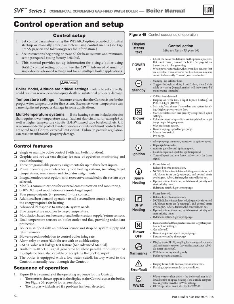
SVF ™ Series 1 COMMERCIAL CONDENSING GAS-FIRED WATER BOILER — Boiler Manual
Part number 550-100-200/101862
Figure 49 Control sequence of operation
Control features ❏ Single or multiple boiler control (with lead boiler rotation). ❏ Graphic and robust text display for ease of operation monitoring and
troubleshooting. ❏ Three programmable priority assignments for up to three heat inputs. ❏ Preset operating parameters for typical heating systems, including target
temperatures, reset curves and circulator assignments. ❏ Integral outdoor reset option, with reset curves matched to the system type
selected. ❏ ModBus communications for external communication and monitoring. ❏ 0-10VDC input modulation or remote target input. ❏ Four pump outputs, 3 – powered, 1– dry contact. ❏ Additional heat demand operation to call a second heat source to help supply
the energy required for heating. ❏ Advanced PI response to anticipate system needs. ❏ Flue temperature modifier to target temperature. ❏ Modulation based on flue sensor and boiler/system supply/return sensors. ❏ Dual temperature sensors on boiler outlet and flue, providing redundant
protection. ❏ Boiler is shipped with an outdoor sensor and strap on system supply and
return sensors. ❏ Blower speed modulation to control boiler firing rate. ❏ Alarm relay on error/fault for use with an audible safety. ❏ CSD-1 Valve seat leakage test feature (See Advanced Manual). ❏ Built-in 0–10 VDC signal generator to allow parallel modulation of
multiple boilers; also capable of accepting 0–10 VDC input. ❏ The boiler is equipped with a low water cutoff, factory wired to the
Control, manually reset through the Control.
Sequence of operation1. Figure 49 is a summary of the operating sequence for the Control.
• The statuses shown appear in the display as the Control cycles the boiler. See Figure 53, page 66 for screen shots.
• The display will flash red if a problem has been detected.
Display status
text
Control action(Also see Figure 53, page 66)
POWER UP
• Check the boiler model listed on the power-up screen. If it is not correct, turn off the boiler. See page 69 for instructions to change setting.
• When power is turned on, the screen lists sensors that are detected. If any sensor is not listed, make sure it is connected correctly. Turn off power and restart.
Standby
• Standby - no calls for heat.• Toggles through no dots, 1 dot, 2 dots, then 3 dots
while in standby (wrench symbol will show instead if maintenance is needed).
Blower ON
• Call for heat detected.• Display on with BLUE light (space heating) or
PURPLE light (DHW).• Start min/max timers if more than one system is call-
ing - highest priority starts first.• Start circulators for this priority setup based upon
settings.• Calculate target temp — If sensor temp is below target
temp, begin firing sequence.• Wait on closure switch.• Blower to purge speed for prepurge.• Min air flow switch.• Pre-purge.
Ignition
• After prepurge times out, transition to ignition speed.• Begin ignition cycle.• Activate gas valve and ignition spark.• Continue ignition spark for ignition period.• Turn off spark and use flame rod to check for flame
signal.
SpaceHeating
• Flame detected.• Release boiler to modulation.• NOTE: If flame is not detected, the gas valve is turned
off, blower turns on (postpurge), and control starts cycle again. After 2 failures, the control locks out.
• If priority timer times out, switch to next priority and start priority timer.
• If demand satisfied, go to postpurge.
DHWHeating
• Flame detected.• Release boiler to modulation.• NOTE: If flame is not detected, the gas valve is turned
off, blower turns on (postpurge), and control starts cycle again. After 2 failures, the control locks out.
• If priority timer times out, switch to next priority and start priority timer.
• If demand satisfied, go to postpurge.
Blower OFF
• Demand satisfied (temperature reaches target tempera-ture or limit setting).
• Gas valve off.• Blower to ignition speed for postpurge.• Return to standby after purge.
Maintenance
• Display turns BLUE, toggling between graphic screen and maintenance screen (occurs if maintenance sched-ule timer times out).
• Will show during standby only.• Boiler operates as normal.
Error/fault
• Display turns RED due to error or limit event.• Flashing display means lockout condition.
WWSD
• Warm weather shut down - the boiler will not be al-lowed to fire on space heating if the outside tempera-ture is greater than the WWSD setting.
• DHW operation is not affected by WWSD.
Control setup1. Set control parameters using the WIZARD option provided on initial
start-up or manually enter parameters using control menus (see Fig-ure 56, page 68 and following pages for information.)
2. See instructions beginning on page 63 for basic systems and minimum settings required (using factory defaults).
3. This manual provides set-up information for a single boiler using BASIC control setting options. See the SVFTM Advanced Manual for single-boiler advanced settings and for all multiple boiler applications.
Boiler Model, Altitude are critical settings. Failure to set correctly could result in severe personal injury, death or substantial property damage.
Temperature settings — You must ensure that the Control is set for the proper water temperatures for the system. Excessive water temperature can cause significant property damage in some applications.
Multi-temperature systems — If the heating system includes circuits that require lower temperature water (radiant slab circuits, for example) as well as higher temperature circuits (DHW, finned tube baseboard, etc.), it is recommended to protect low-temperature circuits with limit controls that are wired to an Control external limit circuit. Failure to provide regulation can result in substantial property damage.
Control operation and setup
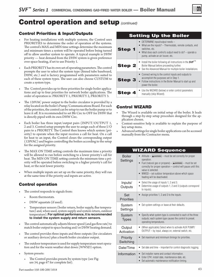
SVF ™ Series 1 COMMERCIAL CONDENSING GAS-FIRED WATER BOILER — Boiler Manual
Part number 550-100-200/1018 63
Control Priorities & Input/Outputs• For heating installations with multiple systems, the Control uses
PRIORITIES to determine the order of operation of the systems. The control’s MAX and MIN time settings determine the maximum and minimum times a system will be operated before being turned off to allow another system to operate. A typical example is DHW priority — heat demand from the DHW system is given preference over space heating, if set to use Priority 1.
• Each PRIORITY has its own set of operating parameters. The control prompts the user to select the system type (finned tube baseboard, DHW, etc.) and is factory programmed with parameters suited to each of these system types. The user can also choose CUSTOM to create a system type.
• The Control provides up to three priorities for single boiler applica-tions and up to four priorities for network boiler applications. The order of operation is: PRIORITY 1, PRIORITY 2, PRIORITY 3.
• The 120VAC power output to the boiler circulator is provided by a relay located on the boiler’s Pump/Communications Board. For each of the priorities, the control can be setup to run the boiler pump or to leave it off. It is recommended to set Blr Circ to OFF for DHW that is directly piped with its own DHW Circ.
• Each boiler has three input/output pairs (INPUT/OUTPUT 1, 2 and 3. Control setup prompts the user to assign each of these I/O pairs to a PRIORITY. The Control then knows which system (pri-ority) to operate when the input receives a call for heat. On a call for heat to an input, the Control closes the corresponding output (120VAC) and begins controlling the boilers according to the setup for the assigned priority.
• The MAX ON TIME setting controls the maximum time a priority will be allowed to run before switching to a lower priority’s call for heat. The MIN ON TIME setting controls the minimum time a pri-ority will be operated before switching to a higher priority’s call for heat, or the next lower priority.
• When multiple inputs are set up on the same priority, they will run at the same time if the priority and inputs are active.
Control operation
• The control responds to signals from:
• Room thermostats.• DHW aquastats (if used).• Temperature sensors (boiler return, boiler supply, flue tempera-
ture) and, when used, system supply and system return, outdoor temperature). For optimal performance, it is recommended to install the system supply and return sensors.
• The control automatically adjusts blower speed (and gas flow rate) to match boiler output to space heating and/or DHW heating demand.
• The control provides three inputs and three outputs (for circulators or auxiliary devices) plus a fourth boiler circulator output.
• The outdoor temperature is used for supply temperature reset opera-tion and for the warm weather shut down (WWSD) option.
• System presets:
• The Control provides presets by system type (see Fig-ure 54, page 67 for complete list).
Setting Up the Boiler
Step 1
• DETERMINE input/output needs –• What are the inputs? – Thermostats, remote contacts, end
switches, etc.• What does each control’s output need to do? – operate a
pump, activate an air louver, etc.
Step 2• Install the boiler following all instructions in the SVFTM
Boiler Manual before proceeding further.• See the Advanced Manual for multiple boiler installations.
Step 3• Connect wiring to the control inputs and outputs to
accomplish the purposes set in Step 1.• Follow instructions in the Boiler Manual to start up and
power the boiler.
Step 4• Use the WIZARD (below) or enter control parameters
manually (skip Wizard).
Control WIZARD• The Wizard is available on initial setup of the boiler. It leads
through a step-by-step setup procedure designed for the ap-plication chosen.
• Context-sensitive help is available to explain the purpose of key setup items.
• Advanced settings for single boiler applications can be accessed manually from the Contractor menu.
WIZARD SequenceBoiler
Settings• Altitude – – must be set correctly for proper
operation.• Fuel (natural gas or propane) – – must be set
correctly for proper operation – control will pause until this value is selected.
• WWSD – set outdoor temperature above which space heating will be deactivated.
Inputs/Outputs
• Select the usage of inputs 1, 2 and 3.• Determine usage of outputs 1, 2 and 3 (outputs correspond
to inputs).
SetPriorities
• Assign priorities 1, 2 and 3 to the inputs.
SystemSettings
• Set system settings or leave at their defaults.
SystemTypes
• Specify what system type is connected to each of the three outputs; each system type causes the control to preset. operating temperatures.
OutputActivation
• (When applicable) Select when to activate AUX PUMP/OUTPUT – by input, always on, external switch, etc.
Priority Switching
• Set maximum and minimum timings for priorities.
Date/Time • Set date and time – important for control diagnostic logging.
Information • Set installer name and contact information.• Enter CP#, install date, maintenance date, etc.• Set automatic maintenance notification timing.
Control operation and setup (continued)
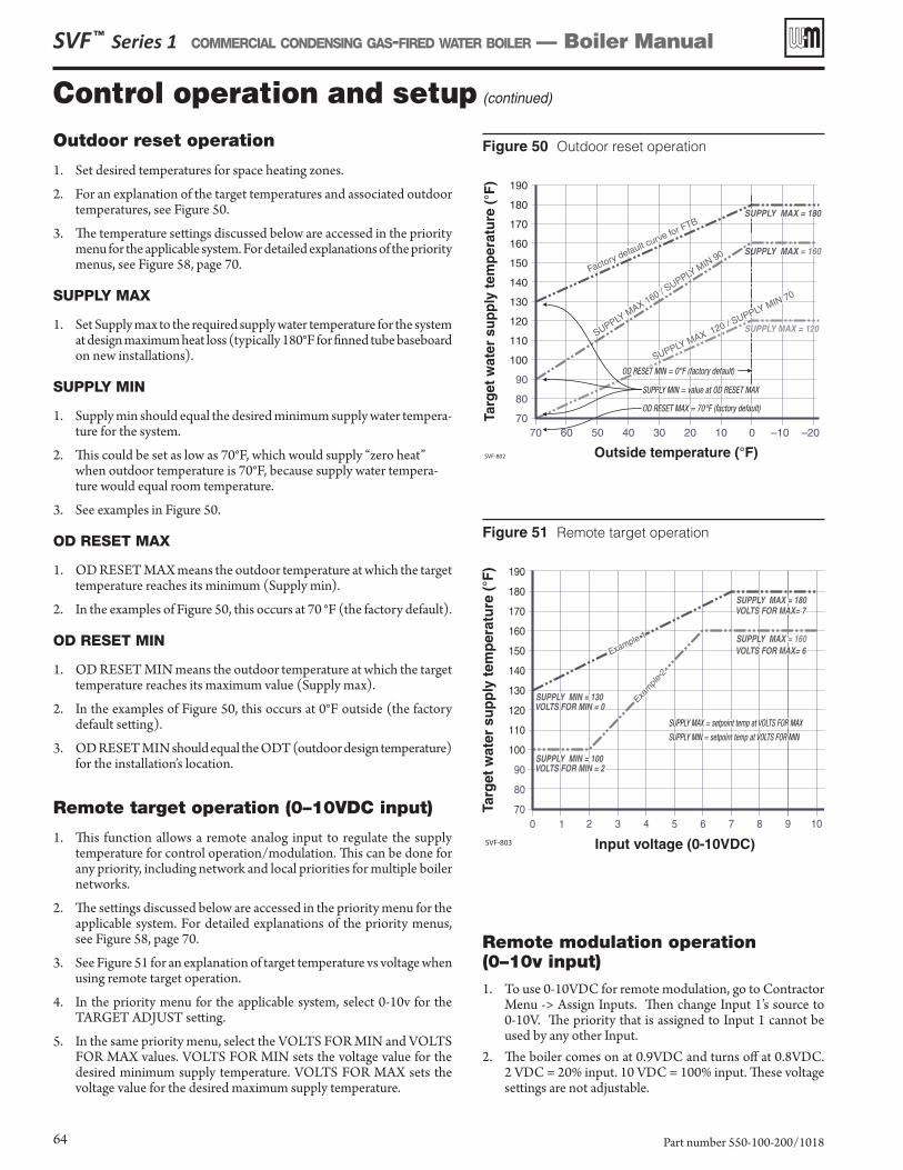
SVF ™ Series 1 COMMERCIAL CONDENSING GAS-FIRED WATER BOILER — Boiler Manual
Part number 550-100-200/101864
Outdoor reset operation
1. Set desired temperatures for space heating zones.
2. For an explanation of the target temperatures and associated outdoor temperatures, see Figure 50.
3. The temperature settings discussed below are accessed in the priority menu for the applicable system. For detailed explanations of the priority menus, see Figure 58, page 70.
SUPPLY MAX
1. Set Supply max to the required supply water temperature for the system at design maximum heat loss (typically 180°F for finned tube baseboard on new installations).
SUPPLY MIN
1. Supply min should equal the desired minimum supply water tempera-ture for the system.
2. This could be set as low as 70°F, which would supply “zero heat” when outdoor temperature is 70°F, because supply water tempera-ture would equal room temperature.
3. See examples in Figure 50.
OD RESET MAX
1. OD RESET MAX means the outdoor temperature at which the target temperature reaches its minimum (Supply min).
2. In the examples of Figure 50, this occurs at 70 °F (the factory default).
OD RESET MIN
1. OD RESET MIN means the outdoor temperature at which the target temperature reaches its maximum value (Supply max).
2. In the examples of Figure 50, this occurs at 0°F outside (the factory default setting).
3. OD RESET MIN should equal the ODT (outdoor design temperature) for the installation’s location.
Remote target operation (0–10VDC input)
1. This function allows a remote analog input to regulate the supply temperature for control operation/modulation. This can be done for any priority, including network and local priorities for multiple boiler networks.
2. The settings discussed below are accessed in the priority menu for the applicable system. For detailed explanations of the priority menus, see Figure 58, page 70.
3. See Figure 51 for an explanation of target temperature vs voltage when using remote target operation.
4. In the priority menu for the applicable system, select 0-10v for the TARGET ADJUST setting.
5. In the same priority menu, select the VOLTS FOR MIN and VOLTS FOR MAX values. VOLTS FOR MIN sets the voltage value for the desired minimum supply temperature. VOLTS FOR MAX sets the voltage value for the desired maximum supply temperature.
Figure 50 Outdoor reset operation
SVF-802
Figure 51 Remote target operation
SVF-803
Remote modulation operation (0–10v input)1. To use 0-10VDC for remote modulation, go to Contractor
Menu -> Assign Inputs. Then change Input 1’s source to 0-10V. The priority that is assigned to Input 1 cannot be used by any other Input.
2. The boiler comes on at 0.9VDC and turns off at 0.8VDC. 2 VDC = 20% input. 10 VDC = 100% input. These voltage settings are not adjustable.
Control operation and setup (continued)
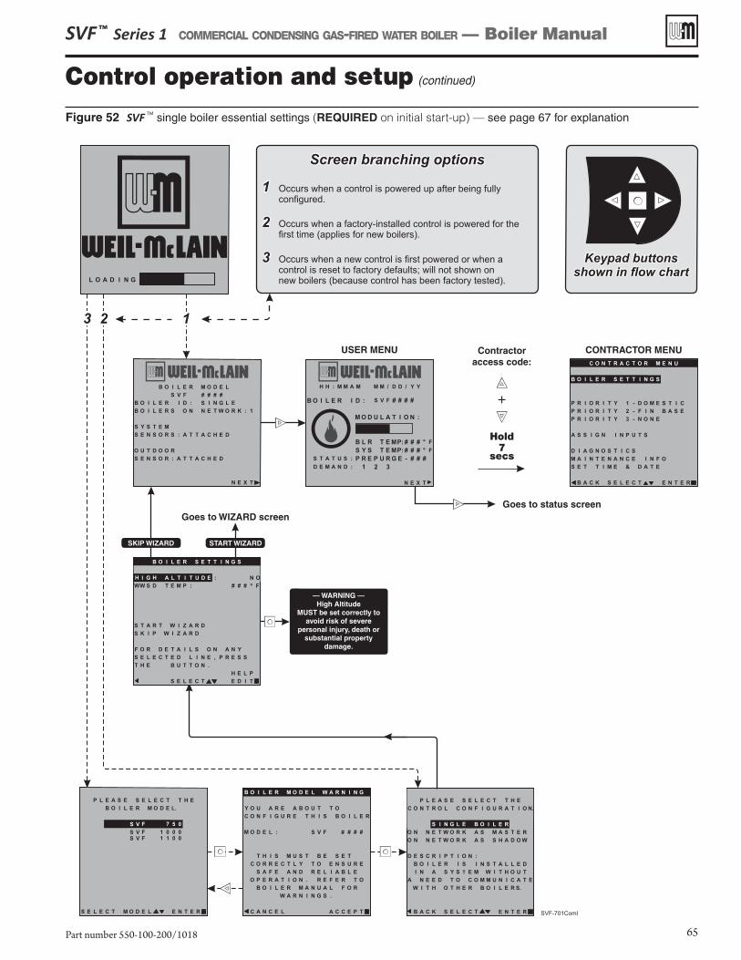
SVF ™ Series 1 COMMERCIAL CONDENSING GAS-FIRED WATER BOILER — Boiler Manual
Part number 550-100-200/1018 65
Figure 52 SVF TM single boiler essential settings (REQUIRED on initial start-up) — see page 67 for explanation
Control operation and setup (continued)
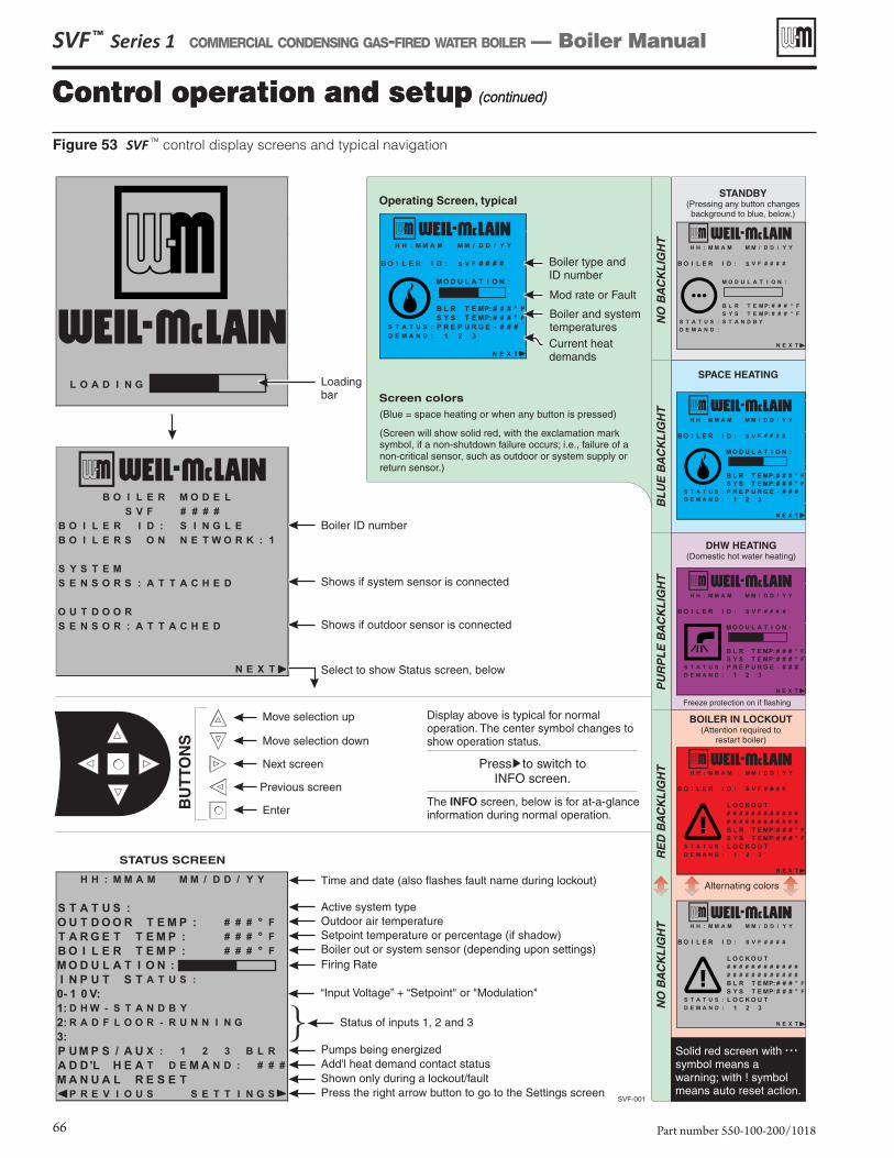
SVF ™ Series 1 COMMERCIAL CONDENSING GAS-FIRED WATER BOILER — Boiler Manual
Part number 550-100-200/101866
Figure 53 SVF TM control display screens and typical navigation
Control operation and setup (continued)Control operation and setup (continued)
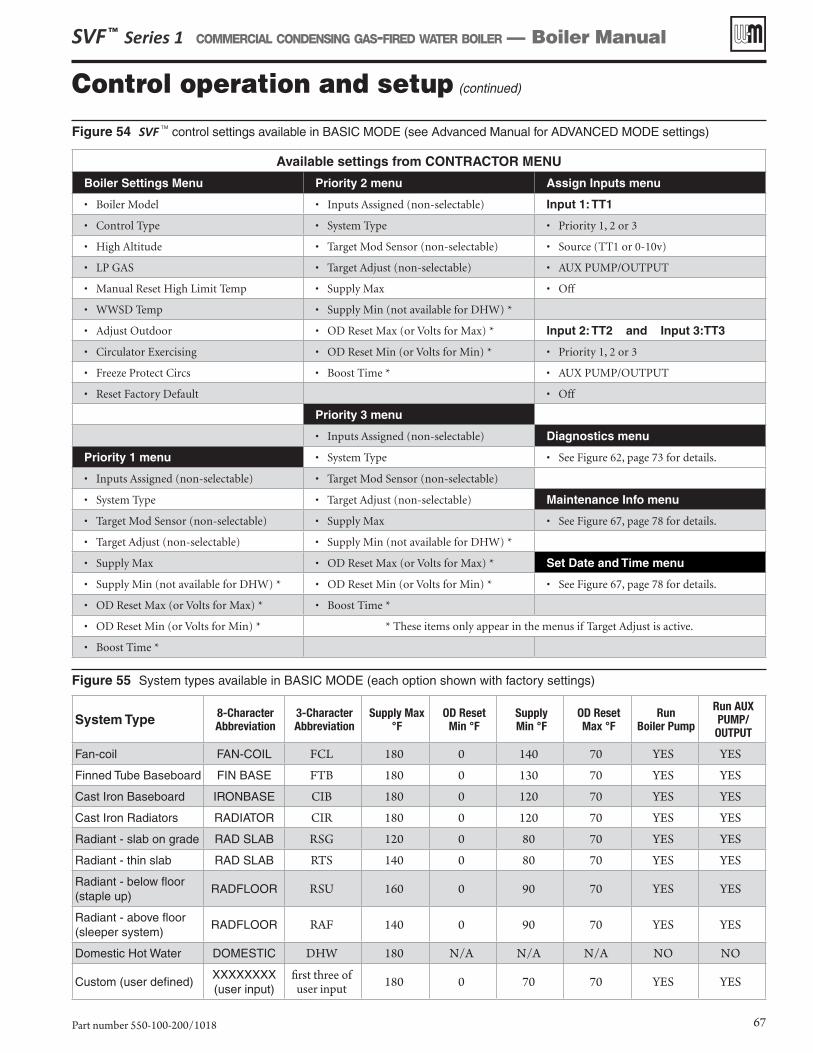
SVF ™ Series 1 COMMERCIAL CONDENSING GAS-FIRED WATER BOILER — Boiler Manual
Part number 550-100-200/1018 67
Control operation and setup (continued)
Figure 54 SVF TM control settings available in BASIC MODE (see Advanced Manual for ADVANCED MODE settings)
Figure 55 System types available in BASIC MODE (each option shown with factory settings)
Available settings from CONTRACTOR MENU
Boiler Settings Menu Priority 2 menu Assign Inputs menu
• Boiler Model • Inputs Assigned (non-selectable) Input 1: TT1
• Control Type • System Type • Priority 1, 2 or 3
• High Altitude • Target Mod Sensor (non-selectable) • Source (TT1 or 0-10v)
• LP GAS • Target Adjust (non-selectable) • AUX PUMP/OUTPUT
• Manual Reset High Limit Temp • Supply Max • Off
• WWSD Temp • Supply Min (not available for DHW) *
• Adjust Outdoor • OD Reset Max (or Volts for Max) * Input 2: TT2 and Input 3:TT3
• Circulator Exercising • OD Reset Min (or Volts for Min) * • Priority 1, 2 or 3
• Freeze Protect Circs • Boost Time * • AUX PUMP/OUTPUT
• Reset Factory Default • Off
Priority 3 menu
• Inputs Assigned (non-selectable) Diagnostics menu
Priority 1 menu • System Type • See Figure 62, page 73 for details.
• Inputs Assigned (non-selectable) • Target Mod Sensor (non-selectable)
• System Type • Target Adjust (non-selectable) Maintenance Info menu
• Target Mod Sensor (non-selectable) • Supply Max • See Figure 67, page 78 for details.
• Target Adjust (non-selectable) • Supply Min (not available for DHW) *
• Supply Max • OD Reset Max (or Volts for Max) * Set Date and Time menu
• Supply Min (not available for DHW) * • OD Reset Min (or Volts for Min) * • See Figure 67, page 78 for details.
• OD Reset Max (or Volts for Max) * • Boost Time *
• OD Reset Min (or Volts for Min) * * These items only appear in the menus if Target Adjust is active.
• Boost Time *
System Type 8-Character Abbreviation
3-Character Abbreviation
Supply Max °F
OD Reset Min °F
Supply Min °F
OD Reset Max °F
Run Boiler Pump
Run AUX PUMP/OUTPUT
Fan-coil FAN-COIL FCL 180 0 140 70 YES YES
Finned Tube Baseboard FIN BASE FTB 180 0 130 70 YES YES
Cast Iron Baseboard IRONBASE CIB 180 0 120 70 YES YES
Cast Iron Radiators RADIATOR CIR 180 0 120 70 YES YES
Radiant - slab on grade RAD SLAB RSG 120 0 80 70 YES YES
Radiant - thin slab RAD SLAB RTS 140 0 80 70 YES YES
Radiant - below floor (staple up)
RADFLOOR RSU 160 0 90 70 YES YES
Radiant - above floor (sleeper system)
RADFLOOR RAF 140 0 90 70 YES YES
Domestic Hot Water DOMESTIC DHW 180 N/A N/A N/A NO NO
Custom (user defined)XXXXXXXX(user input)
first three of user input 180 0 70 70 YES YES
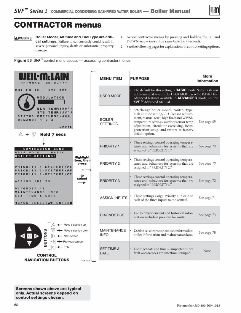
SVF ™ Series 1 COMMERCIAL CONDENSING GAS-FIRED WATER BOILER — Boiler Manual
Part number 550-100-200/101868
Screens shown above are typical only. Actual screens depend on control settings chosen.
CONTRACTOR menusBoiler Model, Altitude and Fuel Type are criti-cal settings. Failure to set correctly could result in severe personal injury, death or substantial property damage.
1. Access contractor menus by pressing and holding the UP and DOWN arrow keys at the same time for 7 seconds.
2. See the following pages for explanations of control setting options.
MENU ITEM PURPOSEMore
information
USER MODE
• The default for this setting is BASIC mode. Screens shown in this manual assume the USER MODE is set to BASIC. For advanced features available in ADVANCED mode, see the SVF TM Advanced Manual.
BOILERSETTINGS
• Set/change boiler model, control type, high altitude setting, ODT sensor require-ment, manual reset, high limit and WWSD temperature settings, outdoor sensor temp adjustment, circulator exercising, freeze protection setup, and restore to factory default option.
See page 69
PRIORITY 1• These settings control operating tempera-
tures and behaviors for systems that are assigned to “PRIORITY 1.”
See page 70
PRIORITY 2• These settings control operating tempera-
tures and behaviors for systems that are assigned to “PRIORITY 2.”
See page 70
PRIORITY 3• These settings control operating tempera-
tures and behaviors for systems that are assigned to “PRIORITY 3.”
See page 70
ASSIGN INPUTS • These settings assign Priority 1, 2 or 3 to each of the three inputs to the control.
See page 71
DIAGNOSTICS • Use to review current and historical infor-mation including previous lockouts.
See page 73
MAINTENANCEINFO
• Used to set contractor contact information, boiler information and maintenance dates.
See page 78
SET TIME & DATE
• Use to set date and time — important since fault occurrences are date/time stamped.
None
Figure 56 SVF TM control menu access — accessing contractor menus
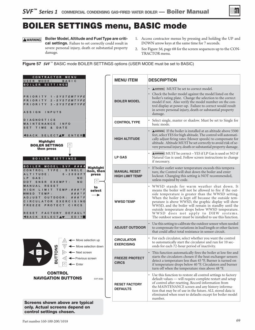
SVF ™ Series 1 COMMERCIAL CONDENSING GAS-FIRED WATER BOILER — Boiler Manual
Part number 550-100-200/1018 69
Screens shown above are typical only. Actual screens depend on control settings chosen.
BOILER SETTINGS menu, BASIC modeBoiler Model, Altitude and Fuel Type are criti-cal settings. Failure to set correctly could result in severe personal injury, death or substantial property damage.
1. Access contractor menus by pressing and holding the UP and DOWN arrow keys at the same time for 7 seconds.
2. See Figure 56, page 68 for the screen sequences up to the CON-TRACTOR menu.
MENU ITEM DESCRIPTION
BOILER MODEL
• MUST be set to correct model.
• Check the boiler model against the model listed on the boiler’s rating plate. Change the selection to the correct model if not. Also verify the model number on the con-trol display at power-up. Failure to correct would result in severe personal injury, death or substantial property damage.
CONTROL TYPE • Select single, master or shadow. Must be set to Single for basic mode.
HIGH ALTITUDE
• If the boiler is installed at an altitude above 5500 feet, select YES for high altitude. The control will automati-cally adjust firing rates (blower speeds) to compensate for altitude. Altitude MUST be set correctly to avoid risk of se-vere personal injury, death or substantial property damage.
LP GAS• MUST be correct – YES if LP Gas is used or NO if
Natural Gas is used. Follow screen instructions to change if necessary.
MANUAL RESET HIGH LIMIT TEMP
• If boiler outlet water temperature exceeds this tempera-ture, the Control will shut down the boiler and enter lockout. Changing this setting is NOT recommended, unless required by code.
WWSD TEMP
• WWSD stands for warm weather shut down. It means the boiler will not be allowed to fire if the out-side temperature is greater than the WWSD setting. When the boiler is kept off because the outside tem-perature is above WWSD, the graphic display will show WWSD, and the boiler will remain in standby until the outside temperature drops below WWSD temperature. W W S D d o e s n o t a p p l y t o D H W s y s t e m s . The outdoor sensor must be installed to use this function.
ADJUST OUTDOOR• Use this setting to calibrate the outdoor sensor when needed
to compensate for variations in lead length or other factors that could affect total resistance in sensor circuit.
CIRCULATOR EXERCISING
• For each circulator, select whether you want the control to automatically start the circulator and run for 10 sec-onds for each 72-hour period of inactivity.
FREEZE PROTECT CIRCS
• This function automatically fires the boiler at low fire and starts the circulators chosen if the heat exchanger sensors detect a temperature less than 45 °F. Burner is turned on if temperature drops below 40 °F. Circulators and burner turn off when the temperature rises above 48 °F.
RESET FACTORY DEFAULTS
• Use this function to restore all control settings to factory default values — will require complete restart and setup of control after resetting. Record information from the MAINTENANCE screen and any history informa-tion that may be of use in the future. ALL stored data is eliminated when reset to defaults except for boiler model number.
Figure 57 SVF TM BASIC mode BOILER SETTINGS options (USER MODE must be set to BASIC)
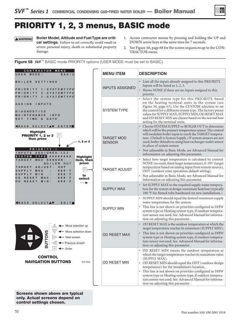
SVF ™ Series 1 COMMERCIAL CONDENSING GAS-FIRED WATER BOILER — Boiler Manual
Part number 550-100-200/101870
Figure 58 SVF TM BASIC mode PRIORITY options (USER MODE must be set to BASIC)
Screens shown above are typical only. Actual screens depend on control settings chosen.
PRIORITY 1, 2, 3 menus, BASIC modeBoiler Model, Altitude and Fuel Type are criti-cal settings. Failure to set correctly could result in severe personal injury, death or substantial property damage.
1. Access contractor menus by pressing and holding the UP and DOWN arrow keys at the same time for 7 seconds.
2. See Figure 56, page 68 for the screen sequences up to the CON-TRACTOR menu.
MENU ITEM DESCRIPTION
INPUTS ASSIGNED
• Lists all the inputs already assigned to this PRIORITY. Inputs will be listed as 1, 2, 3.
• Shows NONE if there are no inputs assigned to this priority .
SYSTEM TYPE
• Select the system type for this PRIORITY, based on the heating terminal units in the system (see Figure 54, page 67). Use the CUSTOM selection to set the control for a different system type. The factory preset values for SUPPLY MAX, SUPPLY MIN, OD RESET MAX and OD RESET MIN are chosen based on the normal best setting for the terminal units.
TARGET MOD SENSOR
• Choose SYSTEM SUPPLY or BOILER OUT to determine which will be the primary temperature sensor. The control will modulate boiler input to reach the TARGET tempera-ture. (Default is System Supply.) If system sensors are not used, boiler defaults to using heat exchanger outlet sensor in place of system sensor.
• Not adjustable in Basic Mode, see Advanced Manual for information on adjusting this parameter.
TARGET ADJUST
• Select how target temperature is calculated by control: NONE (no reset, fixed target temperature), 0-10V (target temperature based on analog input from remote source), ODT (outdoor reset operation; default setting).
• Not adjustable in Basic Mode, see Advanced Manual for information on adjusting this parameter.
SUPPLY MAX• Set SUPPLY MAX to the required supply water tempera-
ture for the system at design maximum heat loss (typically 180 °F for finned tube baseboard on new installations.)
SUPPLY MIN
• SUPPLY MIN should equal the desired minimum supply water temperature for the system.
• This line is not shown on priorities configured as DHW system type or Heating system type, if outdoor tempera-ture sensor not used. See Advanced Manual for informa-tion on adjusting this parameter .
OD RESET MAX
• OD RESET MAX is the outdoor temperature at which the target temperature reaches its minimum (SUPPLY MIN).
• This line is not shown on priorities configured as DHW system type or Heating system type, if outdoor tempera-ture sensor not used. See Advanced Manual for informa-tion on adjusting this parameter .
OD RESET MIN
• OD RESET MIN means the outdoor temperature at which the target temperature reaches its maximum value (SUPPLY MAX).
• OD RESET MIN should equal the ODT (outdoor design temperature) for the installation’s location.
• This line is not shown on priorities configured as DHW system type or Heating system type, if outdoor tempera-ture sensor not used. See Advanced Manual for informa-tion on adjusting this parameter .
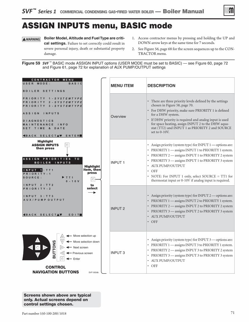
SVF ™ Series 1 COMMERCIAL CONDENSING GAS-FIRED WATER BOILER — Boiler Manual
Part number 550-100-200/1018 71
Figure 59 SVF TM BASIC mode ASSIGN INPUT options (USER MODE must be set to BASIC) — see Figure 60, page 72 and Figure 61, page 72 for explanation of AUX PUMP/OUTPUT settings
Screens shown above are typical only. Actual screens depend on control settings chosen.
ASSIGN INPUTS menu, BASIC modeBoiler Model, Altitude and Fuel Type are criti-cal settings. Failure to set correctly could result in severe personal injury, death or substantial property damage.
1. Access contractor menus by pressing and holding the UP and DOWN arrow keys at the same time for 7 seconds.
2. See Figure 56, page 68 for the screen sequences up to the CON-TRACTOR menu.
MENU ITEM DESCRIPTION
Overview
• There are three priority levels defined by the settings chosen in Figure 58, page 70.
• For DHW priority, make sure PRIORITY 1 is defined for a DHW system.
• If DHW priority is required and analog input is used for space heating, assign INPUT 2 to the DHW aqua-stat (TT2) and INPUT 1 as PRIORITY 2 and SOURCE set to 0-10V.
INPUT 1
• Assign priority (system type) for INPUT 1 — options are:
• PRIORITY 1 — assigns INPUT 1 to PRIORITY 1 system.
• PRIORITY 2 — assigns INPUT 1 to PRIORITY 2 system
• PRIORITY 3 — assigns INPUT 1 to PRIORITY 3 system
• AUX PUMP/OUTPUT
• OFF
• NOTE: For INPUT 1 only, select SOURCE = TT1 for thermostat input or 0-10V if analog input is required.
INPUT 2
• Assign priority (system type) for INPUT 2 — options are:
• PRIORITY 1 — assigns INPUT 2 to PRIORITY 1 system.
• PRIORITY 2 — assigns INPUT 2 to PRIORITY 2 system
• PRIORITY 3 — assigns INPUT 2 to PRIORITY 3 system
• AUX PUMP/OUTPUT
• OFF
INPUT 3
• Assign priority (system type) for INPUT 3 — options are:
• PRIORITY 1 — assigns INPUT 3 to PRIORITY 1 system.
• PRIORITY 2 — assigns INPUT 3 to PRIORITY 2 system
• PRIORITY 3 — assigns INPUT 3 to PRIORITY 3 system
• AUX PUMP/OUTPUT
• OFF
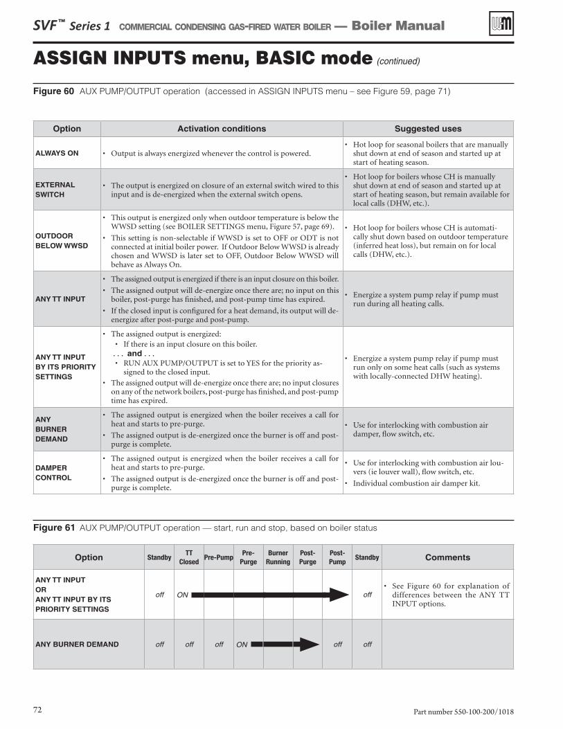
SVF ™ Series 1 COMMERCIAL CONDENSING GAS-FIRED WATER BOILER — Boiler Manual
Part number 550-100-200/101872
ASSIGN INPUTS menu, BASIC mode (continued)
Figure 60 AUX PUMP/OUTPUT operation (accessed in ASSIGN INPUTS menu – see Figure 59, page 71)
Option Activation conditions Suggested uses
ALWAYS ON • Output is always energized whenever the control is powered.• Hot loop for seasonal boilers that are manually
shut down at end of season and started up at start of heating season.
EXTERNALSWITCH
• The output is energized on closure of an external switch wired to this input and is de-energized when the external switch opens.
• Hot loop for boilers whose CH is manually shut down at end of season and started up at start of heating season, but remain available for local calls (DHW, etc.).
OUTDOORBELOW WWSD
• This output is energized only when outdoor temperature is below the WWSD setting (see BOILER SETTINGS menu, Figure 57, page 69).
• This setting is non-selectable if WWSD is set to OFF or ODT is not connected at initial boiler power. If Outdoor Below WWSD is already chosen and WWSD is later set to OFF, Outdoor Below WWSD will behave as Always On.
• Hot loop for boilers whose CH is automati-cally shut down based on outdoor temperature (inferred heat loss), but remain on for local calls (DHW, etc.).
ANY TT INPUT
• The assigned output is energized if there is an input closure on this boiler.
• The assigned output will de-energize once there are; no input on this boiler, post-purge has finished, and post-pump time has expired.
• If the closed input is configured for a heat demand, its output will de-energize after post-purge and post-pump.
• Energize a system pump relay if pump must run during all heating calls.
ANY TT INPUT BY ITS PRIORITY SETTINGS
• The assigned output is energized:• If there is an input closure on this boiler.
. . . and . . .• RUN AUX PUMP/OUTPUT is set to YES for the priority as-
signed to the closed input.
• The assigned output will de-energize once there are; no input closures on any of the network boilers, post-purge has finished, and post-pump time has expired.
• Energize a system pump relay if pump must run only on some heat calls (such as systems with locally-connected DHW heating).
ANYBURNER DEMAND
• The assigned output is energized when the boiler receives a call for heat and starts to pre-purge.
• The assigned output is de-energized once the burner is off and post-purge is complete.
• Use for interlocking with combustion air damper, flow switch, etc.
DAMPER CONTROL
• The assigned output is energized when the boiler receives a call for heat and starts to pre-purge.
• The assigned output is de-energized once the burner is off and post-purge is complete.
• Use for interlocking with combustion air lou-vers (ie louver wall), flow switch, etc.
• Individual combustion air damper kit.
Option StandbyTT
ClosedPre-Pump
Pre-Purge
Burner Running
Post-Purge
Post-Pump
Standby Comments
ANY TT INPUTORANY TT INPUT BY ITS PRIORITY SETTINGS
off ON off• See Figure 60 for explanation of
differences between the ANY TT INPUT options.
ANY BURNER DEMAND off off off ON off off
Figure 61 AUX PUMP/OUTPUT operation — start, run and stop, based on boiler status
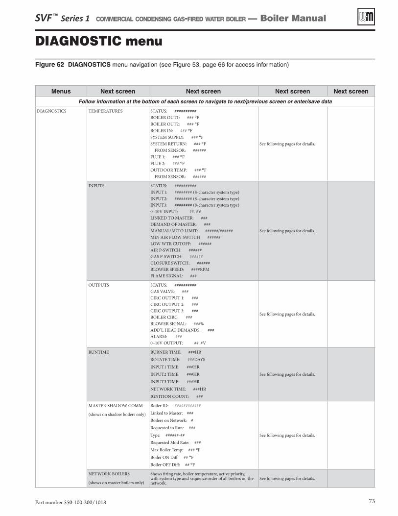
SVF ™ Series 1 COMMERCIAL CONDENSING GAS-FIRED WATER BOILER — Boiler Manual
Part number 550-100-200/1018 73
Figure 62 DIAGNOSTICS menu navigation (see Figure 53, page 66 for access information)
DIAGNOSTIC menu
Menus Next screen Next screen Next screen Next screen
Follow information at the bottom of each screen to navigate to next/previous screen or enter/save data
DIAGNOSTICS TEMPERATURES STATUS: ##########BOILER OUT1: ### ºFBOILER OUT2: ### ºFBOILER IN: ### ºFSYSTEM SUPPLY: ### ºFSYSTEM RETURN: ### ºF FROM SENSOR: ######FLUE 1: ### ºFFLUE 2: ### ºFOUTDOOR TEMP: ### ºF FROM SENSOR: ######
See following pages for details.
INPUTS STATUS: ##########INPUT1: ######## (8-character system type)INPUT2: ######## (8-character system type)INPUT3: ######## (8-character system type)0–10V INPUT: ##. #VLINKED TO MASTER: ###DEMAND OF MASTER: ###MANUAL/AUTO LIMIT: ######/######MIN AIR FLOW SWITCH ######LOW WTR CUTOFF: ######AIR P-SWITCH: ######GAS P-SWITCH: ######CLOSURE SWITCH: ######BLOWER SPEED: ####RPMFLAME SIGNAL: ###
See following pages for details.
OUTPUTS STATUS: ##########GAS VALVE: ###CIRC OUTPUT 1: ###CIRC OUTPUT 2: ###CIRC OUTPUT 3: ###BOILER CIRC: ###BLOWER SIGNAL: ###%ADD’L HEAT DEMANDS: ### ALARM: ### 0–10V OUTPUT: ##. #V
See following pages for details.
RUNTIME BURNER TIME: ###HR
ROTATE TIME: ###DAYS
INPUT1 TIME: ###HR
INPUT2 TIME: ###HR
INPUT3 TIME: ###HR
NETWORK TIME: ###HR
IGNITION COUNT: ###
See following pages for details.
MASTER-SHADOW COMM
(shows on shadow boilers only)
Boiler ID: ############
Linked to Master: ###
Boilers on Network: #
Requested to Run: ###
Type: ######-##
Requested Mod Rate: ###
Max Boiler Temp: ### ºF
Boiler ON Diff: ## ºF
Boiler OFF Diff: ## ºF
See following pages for details.
NETWORK BOILERS
(shows on master boilers only)
Shows firing rate, boiler temperature, active priority, with system type and sequence order of all boilers on the network.
See following pages for details.
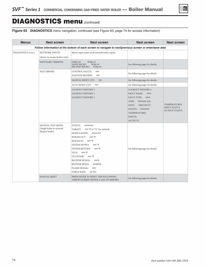
SVF ™ Series 1 COMMERCIAL CONDENSING GAS-FIRED WATER BOILER — Boiler Manual
Part number 550-100-200/101874
DIAGNOSTICS menu (continued)
Figure 63 DIAGNOSTICS menu navigation, continued (see Figure 63, page 74 for access information)
Menus Next screen Next screen Next screen Next screen
Follow information at the bottom of each screen to navigate to next/previous screen or enter/save data
DIAGNOSTICS (cont.) NETWORK INPUTS
(shows on master boilers only)
Shows input status of all network boiler inputs.
SOFTWARE VERSIONS DISPLAY WM#.## MAIN MICRO WM#.## SECOND MICRO WM#.##
See following pages for details.
PAST ERRORS CONTROL FAULTS: ###
IGNITION RETRIES: ###See following pages for details.
MANUAL RESET CNT: ### See following pages for details.
AUTO RESET CNT: ### See following pages for details.
LOCKOUT HISTORY 1
LOCKOUT HISTORY 2
LOCKOUT HISTORY 3
LOCKOUT HISTORY #
FAULT NAME: ####
FAULT TYPE: ####
TIME: HH:MM AM
DATE: MM/DD/YY
STATUS: ########
TEMPERATURES
INPUTS
OUTPUTS
TEMPERATURESINPUT STATUSOUTPUT STATUS
MANUAL TEST MODE (Single boiler or network Shadow boiler)
STATUS: ########
TARGET: ### ºF or “%” for network
MODULATION: ########
BOILER OUT: ### ºF
BOILER IN: ### ºF
SYSTEM SUPPLY: ### ºF
SYSTEM RETURN: ### ºF
FLUE: ### ºF
OUTDOOR: ### ºF
BLOWER SIGNAL: ###%
BLOWER SPEED: ###RPM
FLAME SIGNAL: ###
FORCE RATE: AUTO
See following pages for details.
MANUAL RESET PRESS ENTER TO RESET THE FOLLOWING ERROR (SCREEN SHOWS A LIST OF ERRORS)
See following pages for details.
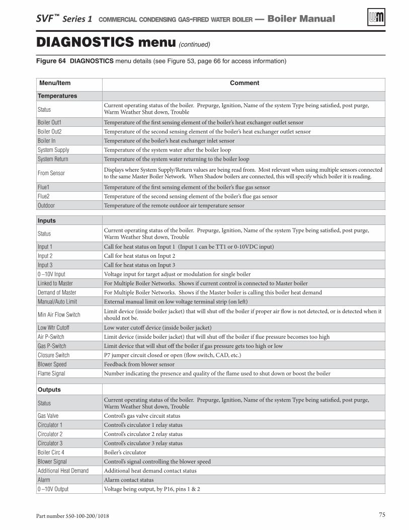
SVF ™ Series 1 COMMERCIAL CONDENSING GAS-FIRED WATER BOILER — Boiler Manual
Part number 550-100-200/1018 75
Figure 64 DIAGNOSTICS menu details (see Figure 53, page 66 for access information)
DIAGNOSTICS menu (continued)
Menu/Item Comment
Temperatures
StatusCurrent operating status of the boiler. Prepurge, Ignition, Name of the system Type being satisfied, post purge, Warm Weather Shut down, Trouble
Boiler Out1 Temperature of the first sensing element of the boiler’s heat exchanger outlet sensorBoiler Out2 Temperature of the second sensing element of the boiler’s heat exchanger outlet sensorBoiler In Temperature of the boiler’s heat exchanger inlet sensorSystem Supply Temperature of the system water after the boiler loopSystem Return Temperature of the system water returning to the boiler loop
From Sensor Displays where System Supply/Return values are being read from. Most relevant when using multiple sensors connected to the same Master Boiler Network. When Shadow boilers are connected, this will specify which boiler it is reading.
Flue1 Temperature of the first sensing element of the boiler’s flue gas sensorFlue2 Temperature of the second sensing element of the boiler’s flue gas sensorOutdoor Temperature of the remote outdoor air temperature sensor
Inputs
Status Current operating status of the boiler. Prepurge, Ignition, Name of the system Type being satisfied, post purge, Warm Weather Shut down, Trouble
Input 1 Call for heat status on Input 1 (Input 1 can be TT1 or 0-10VDC input)Input 2 Call for heat status on Input 2Input 3 Call for heat status on Input 30 –10V Input Voltage input for target adjust or modulation for single boiler Linked to Master For Multiple Boiler Networks. Shows if current control is connected to Master boilerDemand of Master For Multiple Boiler Networks. Shows if the Master boiler is calling this boiler heat demandManual/Auto Limit External manual limit on low voltage terminal strip (on left)
Min Air Flow Switch Limit device (inside boiler jacket) that will shut off the boiler if proper air flow is not detected, or is detected when it should not be.
Low Wtr Cutoff Low water cutoff device (inside boiler jacket)Air P-Switch Limit device (inside boiler jacket) that will shut off the boiler if flue pressure becomes too highGas P-Switch Limit device that will shut off the boiler if gas pressure gets too high or lowClosure Switch P7 jumper circuit closed or open (flow switch, CAD, etc.)Blower Speed Feedback from blower sensorFlame Signal Number indicating the presence and quality of the flame used to shut down or boost the boiler
Outputs
Status Current operating status of the boiler. Prepurge, Ignition, Name of the system Type being satisfied, post purge, Warm Weather Shut down, Trouble
Gas Valve Control’s gas valve circuit statusCirculator 1 Control’s circulator 1 relay statusCirculator 2 Control’s circulator 2 relay statusCirculator 3 Control’s circulator 3 relay statusBoiler Circ 4 Boiler’s circulatorBlower Signal Control’s signal controlling the blower speedAdditional Heat Demand Additional heat demand contact statusAlarm Alarm contact status0 –10V Output Voltage being output, by P16, pins 1 & 2
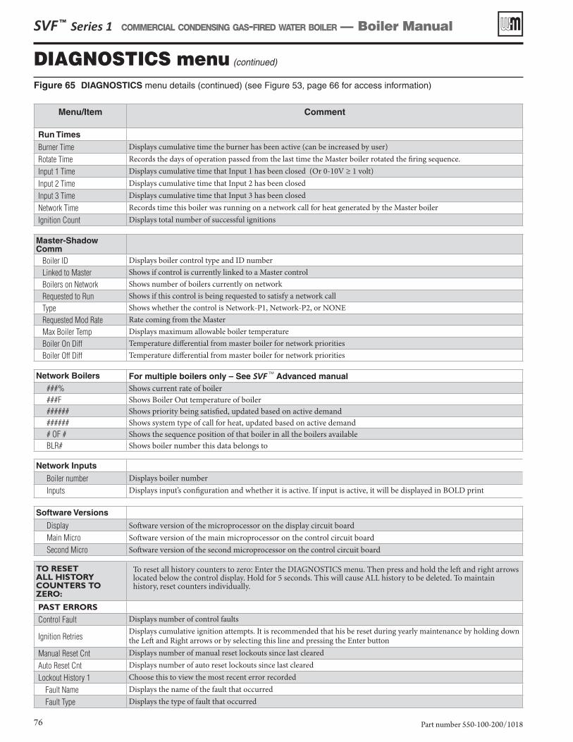
SVF ™ Series 1 COMMERCIAL CONDENSING GAS-FIRED WATER BOILER — Boiler Manual
Part number 550-100-200/101876
Figure 65 DIAGNOSTICS menu details (continued) (see Figure 53, page 66 for access information)
DIAGNOSTICS menu (continued)
Menu/Item Comment
Run Times
Burner Time Displays cumulative time the burner has been active (can be increased by user)Rotate Time Records the days of operation passed from the last time the Master boiler rotated the firing sequence.Input 1 Time Displays cumulative time that Input 1 has been closed (Or 0-10V ≥ 1 volt)Input 2 Time Displays cumulative time that Input 2 has been closedInput 3 Time Displays cumulative time that Input 3 has been closedNetwork Time Records time this boiler was running on a network call for heat generated by the Master boilerIgnition Count Displays total number of successful ignitions
Master-Shadow Comm
Boiler ID Displays boiler control type and ID numberLinked to Master Shows if control is currently linked to a Master controlBoilers on Network Shows number of boilers currently on networkRequested to Run Shows if this control is being requested to satisfy a network callType Shows whether the control is Network-P1, Network-P2, or NONERequested Mod Rate Rate coming from the MasterMax Boiler Temp Displays maximum allowable boiler temperatureBoiler On Diff Temperature differential from master boiler for network prioritiesBoiler Off Diff Temperature differential from master boiler for network priorities
Network Boilers For multiple boilers only – See SVF TM Advanced manual###% Shows current rate of boiler###F Shows Boiler Out temperature of boiler###### Shows priority being satisfied, updated based on active demand###### Shows system type of call for heat, updated based on active demand# OF # Shows the sequence position of that boiler in all the boilers availableBLR# Shows boiler number this data belongs to
Network Inputs
Boiler number Displays boiler numberInputs Displays input’s configuration and whether it is active. If input is active, it will be displayed in BOLD print
Software Versions
Display Software version of the microprocessor on the display circuit boardMain Micro Software version of the main microprocessor on the control circuit boardSecond Micro Software version of the second microprocessor on the control circuit board
TO RESET ALL HISTORY COUNTERS TO ZERO:
To reset all history counters to zero: Enter the DIAGNOSTICS menu. Then press and hold the left and right arrows located below the control display. Hold for 5 seconds. This will cause ALL history to be deleted. To maintain history, reset counters individually.
PAST ERRORS
Control Fault Displays number of control faults
Ignition RetriesDisplays cumulative ignition attempts. It is recommended that his be reset during yearly maintenance by holding down the Left and Right arrows or by selecting this line and pressing the Enter button
Manual Reset Cnt Displays number of manual reset lockouts since last clearedAuto Reset Cnt Displays number of auto reset lockouts since last clearedLockout History 1 Choose this to view the most recent error recorded
Fault Name Displays the name of the fault that occurred Fault Type Displays the type of fault that occurred
SVF ™ Series 1 COMMERCIAL CONDENSING GAS-FIRED WATER BOILER — Boiler Manual
Part number 550-100-200/1018 77
Figure 66 DIAGNOSTICS menu details (continued) (see Figure 53, page 66 for access information)
DIAGNOSTICS menu (continued)
Menu/Item Comment
Time Displays time that lockout occurred Date Displays date that lockout occurred Status Displays what the status of the boiler was at the time of the error Temperatures Choose this to view the Boiler Temperatures at the time of the error Inputs Choose this to view the status of the Boiler Inputs at the time of the error Outputs Choose this to view the status of the Boiler Outputs at the time of the errorLockout History 2 Choose this to view the second most recent error recorded Fault Name Displays the name of the fault that occurred Fault Type Displays the type of fault that occurred Time Displays time that lockout occurred Date Displays date that lockout occurred Status Displays what the status of the boiler was at the time of the error Temperatures Choose this to view the Boiler Temperatures at the time of the error Inputs Choose this to view the status of the Boiler Inputs at the time of the error Outputs Choose this to view the status of the Boiler Outputs at the time of the errorLockout History 3 Choose this to view the third most recent error recorded Fault Name Displays the name of the fault that occurred Fault Type Displays the type of fault that occurred Time Displays time that lockout occurred Date Displays date that lockout occurred Status Displays what the status of the boiler was at the time of the error Temperatures Choose this to view the Boiler Temperatures at the time of the error Inputs Choose this to view the status of the Boiler Inputs at the time of the error Outputs Choose this to view the status of the Boiler Outputs at the time of the error
Manual Test ModeStatus Current operating status of the boiler. Prepurge, Ignition, Name of the system Type being satisfied, post purge,
Warm Weather Shut down, TroubleTarget Calculated target temperature based on outdoor temp or the max target if no ODRModulation Displays what sensor the boiler is using to modulate from. If the boiler is being self-limited, this may also display what
the cause is Temperature of the outlet sensor on the boiler heat exchangerBoiler In Temperature of the inlet sensor on the boiler heat exchangerSystem Supply Temperature of the system water after the boiler loopSystem Return Temperature of the system water returning to the boiler loopFlue Temperature of flue gasesOutdoor Temperature of outdoor airBlower Signal Control’s signal controlling the blower speedBlower Speed Blower’s feedback to the controlFlame Signal Number indicating the presence and quality of the flame used to shut down or boost the boilerForce Rate Used to manually force a rate during a call for heat. Choose auto for normal operation
Manual Reset Reset selected condition
SVF ™ Series 1 COMMERCIAL CONDENSING GAS-FIRED WATER BOILER — Boiler Manual
Part number 550-100-200/101878
MAINTENANCE, DATE AND TIME menus
Figure 67 MAINTENANCE, DATE AND TIME menus — navigation (see Figure 53, page 66 for access information)
MAINTENANCE INFO1. Use this section to enter contractor’s information, CP number, install date and to enter an automatic notice for maintenance (default is 12
months). Because this shows on the display, it is an automatic means of notifying the homeowner of need for scheduled maintenance by the technician. Select RESET REMINDER to reset for the next maintenance date.
SET TIME AND DATE1. Enter current date and time. This allows correct maintenance reminder timing and provides date and time stamp for lockout histories on
ERROR screen in Diagnostic Menu.
Maintenance Info Comment
Name Contractor name to appear in maintenance reminders and during lockoutsPhone Contractor phone numberModel Displays the boiler model selected in the boiler setupCP Number Enter the CP# of the boilerInstalled Enter the date the boiler was installedLast Date Date automatically entered when Reset Reminder is chosen by contractorNext Date Date automatically calculated when Reset Reminder is selected by contractorInterval Settings Contractor selects maintenance reminder frequency based on service historyReset Reminder Contractor selects this to update Last maintenance Date and Next Date. Homeowner uses this to ignore the
reminder and update only the Next Date.
Set Time and Date
Year Set year (homeowner or contractor)Month Set month (homeowner or contractor)Day Set day (homeowner or contractor)Hour Set hour (homeowner or contractor)Minute Set minute (homeowner or contractor)
Startup — fill the systemClean system to remove sediment
You must thoroughly flush the system (without boiler connected) to remove sediment. The high-efficiency heat exchanger can be damaged by buildup or corrosion due to sediment.
1. If necessary, use an approved chemical cleaning agent, following the manufacturer’s guidelines for procedures. a. A list of approved cleaning products is available at www.
Weil-McLain.com. b. See Replacement parts at the end of this manual for Weil-
McLain part numbers to obtain cleaning agents through a Weil-McLain distributor.
2. For zoned systems, flush each zone separately through a purge valve. a. If purge valves and isolation valves are not already installed,
install them to properly clean the system.3. Flush the system until water runs clean and you are sure all piping
is free of sediment.
Do not use petroleum-based cleaning or sealing com-pounds in the boiler system. Damage to elastomer seals and gaskets in the system could occur, resulting in substantial property damage.Before filling the boiler and system with water, verify the water chemistry complies with these instructions.Failure to comply could result in boiler failure or unreli-able operation.
Install a strainer or other mechanical separator device if necessary to ensure sediment will not enter the boiler.
Water chemistry
Water pH between 7.0 and 8.5
1. Maintain boiler water pH between 7.0 and 8.5. Test the water with litmus paper or have it chemically analyzed by a water treat-ment company.
2. If pH differs from above, consult a local water treatment company for treatment needed.
3. Softened water may be used to fill boiler providing Sentinel X100 is added to the system at the proper dosage and properly main-tained. Without Sentinel X100, softened water must not be used or boiler corrosion may occur.
Hardness must be less than 7 grains
1. Consult local water treatment companies for unusually hard water areas (above 7 grains hardness).
Chlorine concentration must be LESS THAN 150 ppm
1. Filling with chlorinated fresh water should be acceptable since drinking water chlorine levels are typically less than 5 ppm.
2. Do not use the boiler to directly heat swimming pool or spa water.3. Do not fill boiler or operate with water containing chlorine in
excess of 150 ppm.
Antifreeze with Inhibitor
Use only antifreeze listed by Weil-McLain as suitable for use with SVFTM Gas Boilers. See additional require-ments in the antifreeze WARNING on the next page.
1. A list of approved antifreeze products is available at www.Weil-McLain.com.
2. See Replacement parts at the end of this manual for Weil-McLain part numbers to obtain antifreeze through a Weil-McLain dis-tributor.
Use the correct amount of antifreeze
1. Determine the freezing temperature needed (to protect against lowest likely temperature the system water will encounter).
2. Find the antifreeze percentage (concentration by volume) needed for this temperature from the antifreeze manufacturer’s data on the antifreeze container.
DO NOT exceed 50% by volume concentration of antifreeze.
3. Calculate the total volume (gallons) of all system piping and components, including the expansion tank and boiler.a. Boiler water content is listed on page 114.b. Include the expansion tank water content.
4. The gallons of antifreeze required equals the total water volume multiplied times the antifreeze percentage required.
Fill and test water system
1. Fill system only after ensuring the water meets the requirements of this manual.
2. Close manual and automatic air vents and boiler drain valve.3. Fill to correct system pressure. Correct pressure will vary with
each application.a. Pressure will rise when boiler is turned on and system water
temperature increases. b. Operating pressure should be no higher than 80% of the relief
valve setting for most systems.4. At initial fill and during boiler startup and testing, check the
system thoroughly for any leaks. Repair all leaks before proceed-ing further.
Eliminate all system leaks. Continual fresh make-up water will reduce boiler life. Minerals can build up in sections, reducing heat transfer, overheating heat exchanger, and causing heat exchanger failure.
X100 inhibitor is recommended
1. It is recommended that the boiler have Sentinel X100 added to the system to prevent damage to the boilers’ heat exchanger. See Replacement Parts section at the end of this manual for re-ordering information.
2. After filling the system as directed in these instructions, use a caulking gun to inject the X100 inhibitor concentrate into the system, or fill with the X100 in its liquid form, following the instructions on the tube or container.
SVF ™ Series 1 COMMERCIAL CONDENSING GAS-FIRED WATER BOILER — Boiler Manual
Part number 550-100-200/1018 79
Startup — fill the system (continued)
FREEZE PROTECTION (when used)
Follow these guidelines to prevent possibility of severe personal injury, death or substantial property damage:
• NEVER use automotive or standard glycol antifreeze,even glycol made for hydronic systems. Use only freeze-prevention fluids recommended by Weil-McLain for application in SVFTM Boiler systems.
• Thoroughly flush any system that has used glycolbefore installing the new SVFTM boiler.
• Review the material safety data sheet (MSDS) for the fluid used with the boiler owner and leave a copy for reference. The MSDS contains information on potential hazards and first aid procedures for exposure or ingestion.
• Check antifreeze inhibitor level at least annually. Glycol concentration and inhibitor levels may change over time. Add antifreeze to increase concentration if necessary. Add inhibitor as needed to bring to acceptable level, using inhibitor test kit to verify.
• When using freeze protection fluid with automatic fill, installa water meter to monitor water make-up. Freeze pro-
tection fluid may leak before the water begins to leak, causing concentration to drop, reducing the freeze protection level.
• DO NOT exceed 50% antifreeze by volume. Antifreeze moves more sluggishly than water and can interfere with heat transfer. At antifreeze concentrations higher than 50%, sludge can develop in the boiler, potentially causing damage to the heat exchanger.
• Clean the system before filling. Always drain and flush the system thoroughly before filling with antifreeze. Sludge, iron oxide deposits and other sediment in the system inhibit flow and can cause rapid breakdown of inhibitors.
• Use only antifreeze recommended by Weil-McLain.
Weil-McLain provides information for application of the antifreeze products listed in this document only for use in Weil-McLain SVFTM boilers. Do not apply these products or instructions for other applications. Local codes may require a backflow preventer or actual discon-nection from city water supply.
3. After adding the inhibitor to the system, allow time for the water to circulate and mix. Then check the inhibitor level. Add additional inhibitor if necessary.
4. See separate instructions or Weil-McLain website for suggested guidelines to determine how much inhibitor to use.
Purge air from water system1. Connect a hose to the purge valve (see purge/drain valves shown
in piping diagrams beginning on page 16). Route the hose to an area where water can drain and be seen.
2. Close the boiler or system isolation valve between the purge valve and fill connection to the system.
3. Close zone isolation valves.4. Open quick-fill valve on cold water make-up line.5. Open purge valve.6. One zone at a time, open the isolation valves. Allow water to run
through the zone, pushing out the air. Run until no noticeable air flow is present. Close the zone isolation valves and proceed with the next zone. Follow this procedure until all zones are purged.
7. Close the quick-fill water valve and purge valve and remove the hose. Open all isolation valves. Watch that system pressure rises to correct cold-fill pressure.
8. After the system has operated for a while, eliminate any residual air by using the manual air vents located throughout the system.
9. If purge valves are not installed in system, open manual air vents in system one at a time, beginning with lowest floor. Close vent when water squirts out. Repeat with remaining vents.
10. Open automatic air vent (diaphragm-type or bladder-type expan-sion tank systems only) one turn.
11. Starting on the lowest floor, open air vents one at a time until water squirts out.
12. Repeat with remaining vents.13. Refill to correct pressure.
Check/verify water chemistry1. The system may have residual substances that could affect water
chemistry.2. After the system has been filled and leak tested, verify water pH
and chloride concentrations are acceptable.3. Verify antifreeze concentration, when used.4. Follow the instructions on the Sentinel test kit to sample the
system water and verify inhibitor concentration.
Check inhibitor and antifreeze concentrations annually 1. Test the pH of a sample of system water at least annually.
a. The pH of the water mixture must be between 7.0 and 8.5. b. Or use the Sentinel inhibitor test kit to check concentration.
2. If pH is outside this range (or inhibitor test kit indicates low level), the inhibitor level may not be sufficient to prevent corrosion.
3. Test antifreeze concentration.
Test antifreeze concentration at least annually. If concentration is low, add antifreeze or drain system and refill with correct mixture. Follow instructions on page 79 to determine amount of antifreeze needed.
4. Check inhibitor level after adjustments are made.
SVF ™ Series 1 COMMERCIAL CONDENSING GAS-FIRED WATER BOILER — Boiler Manual
Part number 550-100-200/101880
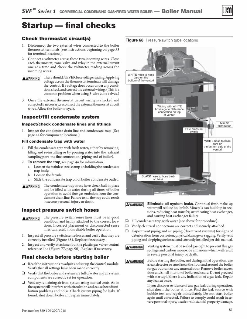
Figure 68 Pressure switch tube locations
Startup — fi nal checksCheck thermostat circuit(s)1. Disconnect the two external wires connected to the boiler
thermostat terminals (see instructions beginning on page 53 for terminal locations).
2. Connect a voltmeter across these two incoming wires. Close each thermostat, zone valve and relay in the external circuit one at a time and check the voltmeter reading across the incoming wires.
Th ere should NEVER be a voltage reading. Applying voltage across the thermostat terminals will damage the control. If a voltage does occur under any condi-tion, check and correct the external wiring. (Th is is a common problem when using 3-wire zone valves.)
3. Once the external thermostat circuit wiring is checked and corrected if necessary, reconnect the external thermostat circuit wires. Allow the boiler to cycle.
Inspect/fi ll condensate systemInspect/check condensate lines and fi ttings
1. Inspect the condensate drain line and condensate trap. (See page 44 for component locations.)
Fill condensate trap with water
1. Fill the condensate trap with fresh water, either by removing, fi lling and re-installing or by pouring water into the exhaust sampling port the fl ue connection (piping end of boiler).
2. To remove the trap, see page 44 for information.a. Loosen the stainless steel clamp on holding the condensate
trap body.b. Loosen the ferrule.c. Slide the condensate trap off of boiler condensate outlet.
Th e condensate trap must have check ball in place and be fi lled with water during all times of boiler operation to avoid fl ue gas emission from the con-densate drain line. Failure to fi ll the trap could result in severe personal injury or death.
Inspect pressure switch hoses Th e pressure switch sense lines must be in good
condition and fi rmly att ached to the correct loca-tions. Incorrect placement or disconnected sense lines can result in unreliable boiler operation.
1. Inspect all pressure switch sense hoses and verify that they are correctly installed ( Figure 68 ). Replace if necessary.
2. Inspect and verify att achment of the plastic gas valve/venturi reference line ( Figure 77, page 90 ). Replace if necessary.
Final checks before starting boiler ❏ Read the instructions to adjust and set up the control module.
Verify that all sett ings have been made correctly. ❏ Verify that the boiler and system are full of water and all system
components are correctly set for operation. ❏ Vent any remaining air from system using manual vents. Air in
the system will interfere with circulation and cause heat distri-bution problems and noise. Check system piping for leaks. If found, shut down boiler and repair immediately.
Eliminate all system leaks. Continual fresh make -up water will reduce boiler life. Minerals can build up in sec-tions, reducing heat transfer, overheating heat exchanger, and causing heat exchanger failure.
❏ Fill condensate trap with water (see above for procedure). ❏ Verify electrical connections are correct and securely att ached. ❏ Inspect vent piping and air piping (direct vent systems) for signs of
deterioration from corrosion, physical damage or sagging. Verify vent piping and air piping are intact and correctly installed per this manual.
Venting system must be sealed gas-tight to prevent fl ue gas spillage and carbon monoxide emissions which will result in severe personal injury or death.
Before starting the boiler, and during initial operation, use a leak detector or smell near the fl oor and around the boiler for gas odorant or any unusual odor. Remove boiler access door and smell interior of boiler enclosure. Do not proceed with startup if there is any indication of a gas leak. Repair any leak at once.
If you discover evidence of any gas leak during operation, shut down the boiler at once. Find the leak source with bubble test and repair immediately. Do not start boiler again until corrected. Failure to comply could result in se-vere personal injury, death or substantial property damage.
SVF ™ Series 1 COMMERCIAL CONDENSING GAS-FIRED WATER BOILER — Boiler Manual
Part number 550-100-200/1018 81
BLACK hose to hose barbon base
WHITE hose to hose barb on the
bottom of the venturi
Min airfl ow switch
Flue pressure switch
WHITE hose to hose barb on
the bottom side of the venturi
Y-fi tting with WHITEhoses go to Reference
connection on topof venturi
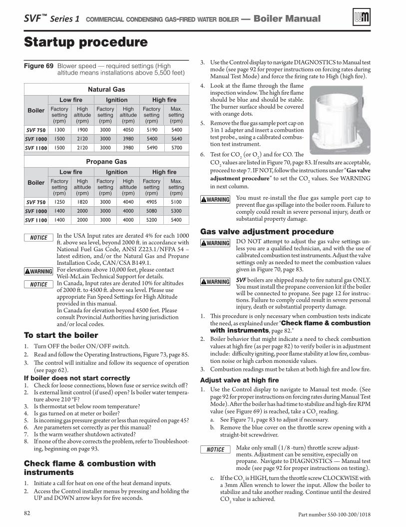
Startup procedure
SVF ™ Series 1 COMMERCIAL CONDENSING GAS-FIRED WATER BOILER — Boiler Manual
Part number 550-100-200/101882
Figure 69 Blower speed — required settings (High altitude means installations above 5,500 feet)
Natural Gas
Boiler
������� Ignition ������Factory setting(rpm)
Highaltitude(rpm)
Factory setting(rpm)
Highaltitude(rpm)
Factory setting(rpm)
Max. setting(rpm)
SVF 750 1300 1900 3000 4050 5190 5400
SVF 1000 1500 2120 3000 3980 5400 5640
SVF 1100 1500 2120 3000 3980 5490 5700
����������
Boiler
������� Ignition ������Factory setting(rpm)
Highaltitude(rpm)
Factory setting(rpm)
Highaltitude(rpm)
Factory setting(rpm)
Max.setting(rpm)
SVF 750 1250 1820 3000 4040 4905 5100
SVF 1000 1400 2000 3000 4000 5080 5300
SVF 1100 1400 2000 3000 4000 5200 5400
In the USA Input rates are derated 4% for each 1000 ft. above sea level, beyond 2000 ft. in accordance with National Fuel Gas Code, ANSI Z223.1/NFPA 54 – latest edition, and/or the Natural Gas and Propane Installation Code, CAN/CSA B149.1.
For elevations above 10,000 feet, please contact Weil-McLain Technical Support for details.
In Canada, Input rates are derated 10% for altitudes of 2000 ft. to 4500 ft. above sea level. Please use appropriate Fan Speed Settings for High Altitude provided in this manual.
In Canada for elevation beyond 4500 feet. Please consult Provincial Authorities having jurisdiction and/or local codes.
To start the boiler1. Turn OFF the boiler ON/OFF switch.2. Read and follow the Operating Instructions, Figure 73, page 85.3. The control will initialize and follow its sequence of operation
(see page 62).If boiler does not start correctly1. Check for loose connections, blown fuse or service switch off?2. Is external limit control (if used) open? Is boiler water tempera-
ture above 210 °F?3. Is thermostat set below room temperature?4. Is gas turned on at meter or boiler?5. Is incoming gas pressure greater or less than required on page 45?6. Are parameters set correctly as per this manual?7. Is the warm weather shutdown activated?8. If none of the above corrects the problem, refer to Troubleshoot-
ing, beginning on page 93.
Check flame & combustion with instruments1. Initiate a call for heat on one of the heat demand inputs.2. Access the Control installer menus by pressing and holding the
UP and DOWN arrow keys for five seconds.
3. Use the Control display to navigate DIAGNOSTICS to Manual test mode (see page 92 for proper instructions on forcing rates during Manual Test Mode) and force the firing rate to High (high fire).
4. Look at the flame through the flame inspection window. The high fire flame should be blue and should be stable. The burner surface should be covered with orange dots.
5. Remove the flue gas sample port cap on 3 in 1 adapter and insert a combustion test probe., using a calibrated combus-tion test instrument.
6. Test for CO2 (or O2) and for CO. The CO2 values are listed in Figure 70, page 83. If results are acceptable, proceed to step 7. IF NOT, follow the instructions under “Gas valve adjustment procedure” to set the CO2 values. See WARNING in next column.
You must re-install the flue gas sample port cap to prevent flue gas spillage into the boiler room. Failure to comply could result in severe personal injury, death or substantial property damage.
Gas valve adjustment procedure DO NOT attempt to adjust the gas valve settings un-
less you are a qualified technician, and with the use of calibrated combustion test instruments. Adjust the valve settings only as needed to meet the combustion values given in Figure 70, page 83.
SVF boilers are shipped ready to fire natural gas ONLY. You must install the propane conversion kit if the boiler will be connected to propane. See page 12 for instruc-tions. Failure to comply could result in severe personal injury, death or substantial property damage.
1. This procedure is only necessary when combustion tests indicate the need, as explained under "Check flame & combustion with instruments, page 82."
2. Boiler behavior that might indicate a need to check combustion values at high fire (as per page 82) to verify boiler is in adjustment include: difficulty igniting, poor flame stability at low fire, combus-tion noise or high carbon monoxide values.
3. Combustion readings must be taken at both high fire and low fire.
Adjust valve at high fire1. Use the Control display to navigate to Manual test mode. (See
page 92 for proper instructions on forcing rates during Manual Test Mode). After the boiler has had time to stabilize and high-fire RPM value (see Figure 69) is reached, take a CO2 reading.a. See Figure 71, page 83 to adjust if necessary.b. Remove the blue cover on the throttle screw opening with a
straight-bit screwdriver.
Make only small (1/8 -turn) throttle screw adjust-ments. Adjustment can be sensitive, especially on propane. Navigate to DIAGNOSTICS — Manual test mode (see page 92 for proper instructions on testing).
c. If the CO2 is HIGH, turn the throttle screw CLOCKWISE with a 3mm Allen wrench to lower the input. Allow the boiler to stabilize and take another reading. Continue until the desired CO2 value is achieved.
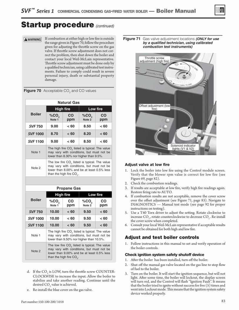
Startup procedure (continued)
If combustion at either high or low fi re is outside the range given in Figure 70 , follow the procedure given for adjusting the thrott le screw on the gas valve. If thrott le screw adjustment does not cor-rect the problem, then shut down the boiler and contact your local Weil-McLain representative. Th rott le screw adjustment must be done only by a qualifi ed technician, using calibrated test instru-ments. Failure to comply could result in severe personal injury, death or substantial property damage.
Figure 70 Acceptable CO2 and CO values
Natural Gas
BoilerHigh fi re Low fi re
%CO2Note 1
COppm
%CO2Note 2
COppm
SVF 750 9.00 < 60 8.50 < 60
SVF 1000 8.70 < 60 8.20 < 60
SVF 1100 9.00 < 60 8.50 < 60
Note 1The high fi re CO2 listed is typical. The value may vary with conditions, but must not be lower than 8.30% nor higher than 9.5%.
Note 2
The low fi re CO2 listed is typical. The value may vary with conditions, but must not be lower than 8.00% and be at least 0.5% less than the high fi re CO2.
����������
BoilerHigh fi re Low fi re
%CO2Note 1
COppm
%CO2Note 2
COppm
SVF 750 10.00 < 60 9.50 < 60
SVF 1000 10.00 < 60 9.50 < 60
SVF 1100 10.00 < 60 9.50 < 60
Note 1The high fi re CO2 listed is typical. The value may vary with conditions, but must not be lower than 9.50% nor higher than 10.5%.
Note 2
The low fi re CO2 listed is typical. The value may vary with conditions, but must not be lower than 9.00% and be at least 0.5% less than the high fi re CO2.
Solenoid indicator lights (V1 & V2)
Throttle screwadjustment (high fi re)
Offset adjustment (low fi re)
Figure 71 Gas valve adjustment locations (ONLY for use by a qualifi ed technician, using calibrated combustion test instruments)
SVF ™ Series 1 COMMERCIAL CONDENSING GAS-FIRED WATER BOILER — Boiler Manual
Part number 550-100-200/1018 83
Adjust valve at low fi re1. Lock the boiler into low fi re using the Control module screen.
Verify that the blower rpm value is correct for low fire (see Figure 69, page 82 ).
2. Check the combustion readings. 3. If results are acceptable at low fi re, verify high fi re readings again.
Restore fi ring rate to AUTO.4. If combustion results are not acceptable, remove the cover screw
over the off set adjustment (see Figure 71, page 83 ). Navigate to DIAGNOSTICS — Manual test mode (see page 92 for proper instructions on testing).
5. Use a T40 Torx driver to adjust the sett ing. Rotate clockwise to increase CO2 , rotate counterclockwise to decrease CO2 . Re-install the cover screw when completed.
6. Consult your local Weil-McLain representative if acceptable results cannot be obtained for both high and low fi re.
Adjust and test boiler controls1. Follow instructions in this manual to set and verify operation of
the boiler controls.
Check ignition system safety shutoff device1. Aft er the boiler has been installed, turn off the boiler. 2. Shut off the manual gas valve located on the gas line to stop fl ow
of fuel to the boiler.3. Turn on the boiler. It will start the ignition sequence, but will not
light. Aft er some time, the boiler will lockout, the display screen will turn red, and the Control will fl ash “Ignition Fault”. It means that the boiler tried to ignite without success for fi ve (5) times and went into Lockout mode. Th is means that the ignition system safety device worked properly.
d. If the CO2 is LOW, turn the thrott le screw COUNTER-CLOCKWISE to increase the input. Allow the boiler to stabilize and take another reading. Continue until the desired CO2 value is achieved.
e. Re-install the blue cover on the gas valve.
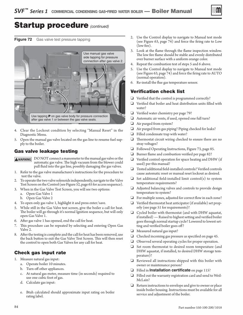
Startup procedure (continued)
SVF ™ Series 1 COMMERCIAL CONDENSING GAS-FIRED WATER BOILER — Boiler Manual
Part number 550-100-200/101884
Check gas input rate1. Measure natural gas input:
a. Operate boiler 10 minutes.b. Turn off other appliances.c. At natural gas meter, measure time (in seconds) required to
use one cubic foot of gas.d. Calculate gas input:
e. Btuh calculated should approximate input rating on boiler rating label.
4. Clear the Lockout condition by selecting “Manual Reset” in the Diagnostic Menu.
5. Open the manual gas valve located on the gas line to resume fuel sup-ply to the boiler.
Gas valve leakage testing DO NOT connect a manometer to the manual gas valve or the
automatic gas valve. Th e high vacuum from the blower could pull fl uid into the gas line, possibly damaging the gas valves.
1. Refer to the gas valve manufacturer’s instructions for the procedure to test the valve.
2. To operate the two valve solenoids independently, navigate to the Valve Test Screen on the Control (see Figure 52, page 65 for access sequence).
3. When in the Gas Valve Test Screen, you will see two options:a. Open Gas Valve 1b. Open Gas Valve 2
4. To open only gas valve 1, highlight it and press enter/save.5. While still in the Gas Valve test screen, give the boiler a call for heat.
Th e boiler will go through it’s normal Ignition sequence, but will only open Gas Valve 1.
6. Aft er gas valve 1 has opened, end the call for heat.7. Th is procedure can be repeated by selecting and entering Open Gas
Valve 2.8. Aft er the testing is complete and the call for heat has been removed, use
the back butt on to exit the Gas Valve Test Screen. Th is will then reset the control to open both Gas Valves for any call for heat.
2. Use the Control display to navigate to Manual test mode (see Figure 63, page 74 ) and force the fi ring rate to Low (low fi re).
3. Look at the fl ame through the fl ame inspection window. Th e low fi re fl ame should be stable and evenly distributed over burner surface with a uniform orange color.
4. Repeat the combustion test of steps 5 and 6 above.5. Use the Control display to navigate to Manual test mode
(see Figure 63, page 74 ) and force the fi ring rate to AUTO (normal operation).
6. Re-install the fl ue gas temperature sensor.
Verifi cation check list ❏ Verifi ed that the control is programmed correctly? ❏ Verifi ed that boiler and heat distribution units fi lled with
water? ❏ Verifi ed water chemistry per page 79 ? ❏ Automatic air vents, if used, opened one full turn? ❏ Air purged from system? ❏ Air purged from gas piping? Piping checked for leaks? ❏ Filled condensate trap with water? ❏ Th ermostat circuit wiring checked to ensure there are no
stray voltages? ❏ Followed Operating Instructions, Figure 73, page 85 . ❏ Burner fl ame and combustion verifi ed per page 82 ? ❏ Verifi ed control operation for space heating and DHW (if
used) per this manual? ❏ Tested additional fi eld-installed controls? Verifi ed controls
cause automatic reset or manual reset lockout as desired. ❏ Set additional fi eld-installed limit control(s) to system
temperature requirements? ❏ Adjusted balancing valves and controls to provide design
temperature to system? ❏ For multiple zones, adjusted for correct fl ow in each zone? ❏ Verifi ed thermostat heat anticipator (if available) set prop-
erly (see page 51 for requirements)? ❏ Cycled boiler with thermostat (and with DHW aquastat,
if installed) — Raised to highest sett ing and verifi ed boiler goes through normal startup cycle? Lowered to lowest set-ting and verifi ed boiler goes off ?
❏ Measured natural gas input? ❏ Checked incoming gas pressure as specifi ed on page 45 . ❏ Observed several operating cycles for proper operation. ❏ Set room thermostat to desired room temperature (and
DHW aquastat, if installed, to desired DHW storage tem-perature)?
❏ Reviewed all instructions shipped with this boiler with owner or maintenance person?
❏ Filled in Installation certifi cate on page 115 ? ❏ Filled out the warranty registration card and send to Weil-
McLain? ❏ Return instructions to envelope and give to owner or place
inside boiler housing. Instructions must be available for all service and adjustment of the boiler.
Figure 72 Gas valve test pressure tapping
2233
Use manual gas valve side tapping for pressure connection after gas valve 2.
Use tapping P on gas valve body for pressure connection after gas valve 1 or between the gas valve seats.
PP
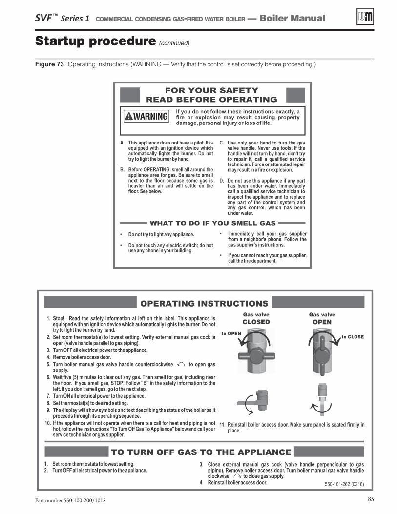
Figure 73 Operating instructions (WARNING — Verify that the control is set correctly before proceeding.)
Startup procedure (continued)
SVF ™ Series 1 COMMERCIAL CONDENSING GAS-FIRED WATER BOILER — Boiler Manual
Part number 550-100-200/1018 85
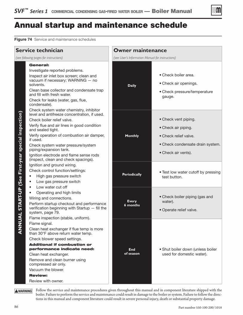
Annual startup and maintenance schedule
Figure 74 Service and maintenance schedules
SVF ™ Series 1 COMMERCIAL CONDENSING GAS-FIRED WATER BOILER — Boiler Manual
Part number 550-100-200/101886
Follow the service and maintenance procedures given throughout this manual and in component literature shipped with the boiler. Failure to perform the service and maintenance could result in damage to the boiler or system. Failure to follow the direc-tions in this manual and component literature could result in severe personal injury, death or substantial property damage.
Service technician
(see following pages for instructions)
Owner maintenance
(see User’s Information Manual for instructions)
AN
NU
AL
ST
AR
T-U
P (
See
Fir
st-y
ear
specia
l in
specti
on
)
General:
Investigate reported problems.Inspect air inlet box screen; clean and vacuum if necessary; WARNING — no solvents.Clean base collector and condensate trap and fill with fresh water.Check for leaks (water, gas, flue, condensate).Check system water chemistry, inhibitor level and antifreeze concentration, if used.Check boiler relief valve.Verify flue and air lines in good condition and sealed tight.Verify operation of combustion air damper, if used.Check system water pressure/system piping/expansion tank.Ignition electrode and flame sense rods (inspect, clean and check spacings).Ignition and ground wiring.Check control function/settings:• High gas pressure switch• Low gas pressure switch• Low water cut off• Operating and high limitsWiring and connections.Perform startup checkout and performance verification beginning with Startup — fill the system, page 79.Flame inspection (stable, uniform).Flame signal.Clean heat exchanger if flue temp is more than 30°F above return water temp.Check blower speed settings.Additional if combustion or performance indicate need:
Clean heat exchanger.Remove and clean burner using compressed air only.Vacuum the blower.Review:
Review with owner.
Daily
• Check boiler area.
• Check air openings.
• Check pressure/temperature gauge.
Monthly
• Check vent piping.
• Check air piping.
• Check relief valve.
• Check condensate drain system.
• Check air vents).
Periodically• Test low water cutoff by pressing
test button.
Every 6 months
• Check boiler piping (gas and water).
• Operate relief valve.
End of season
• Shut boiler down (unless boiler used for domestic water).
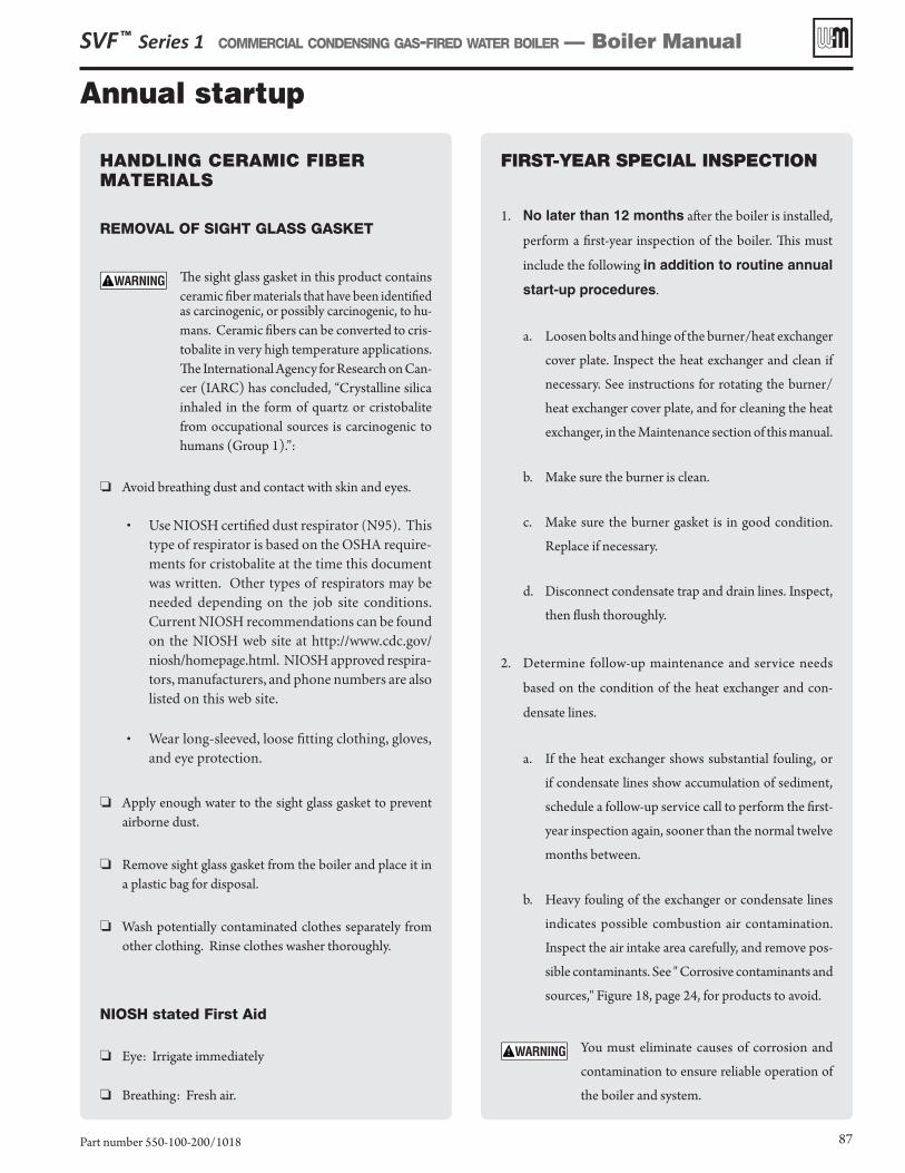
Annual startup
SVF ™ Series 1 COMMERCIAL CONDENSING GAS-FIRED WATER BOILER — Boiler Manual
Part number 550-100-200/1018 87
HANDLING CERAMIC FIBER MATERIALS
REMOVAL OF SIGHT GLASS GASKET
The sight glass gasket in this product contains ceramic fiber materials that have been identified as carcinogenic, or possibly carcinogenic, to hu-mans. Ceramic fibers can be converted to cris-tobalite in very high temperature applications. The International Agency for Research on Can-cer (IARC) has concluded, “Crystalline silica inhaled in the form of quartz or cristobalite from occupational sources is carcinogenic to humans (Group 1).”:
❏ Avoid breathing dust and contact with skin and eyes.
• Use NIOSH certified dust respirator (N95). This type of respirator is based on the OSHA require-ments for cristobalite at the time this document was written. Other types of respirators may be needed depending on the job site conditions. Current NIOSH recommendations can be found on the NIOSH web site at http://www.cdc.gov/niosh/homepage.html. NIOSH approved respira-tors, manufacturers, and phone numbers are also listed on this web site.
• Wear long-sleeved, loose fitting clothing, gloves, and eye protection.
❏ Apply enough water to the sight glass gasket to prevent airborne dust.
❏ Remove sight glass gasket from the boiler and place it in a plastic bag for disposal.
❏ Wash potentially contaminated clothes separately from other clothing. Rinse clothes washer thoroughly.
NIOSH stated First Aid
❏ Eye: Irrigate immediately
❏ Breathing: Fresh air.
FIRST-YEAR SPECIAL INSPECTION
1. No later than 12 months after the boiler is installed,
perform a first-year inspection of the boiler. This must
include the following in addition to routine annual
start-up procedures.
a. Loosen bolts and hinge of the burner/heat exchanger
cover plate. Inspect the heat exchanger and clean if
necessary. See instructions for rotating the burner/
heat exchanger cover plate, and for cleaning the heat
exchanger, in the Maintenance section of this manual.
b. Make sure the burner is clean.
c. Make sure the burner gasket is in good condition.
Replace if necessary.
d. Disconnect condensate trap and drain lines. Inspect,
then flush thoroughly.
2. Determine follow-up maintenance and service needs
based on the condition of the heat exchanger and con-
densate lines.
a. If the heat exchanger shows substantial fouling, or
if condensate lines show accumulation of sediment,
schedule a follow-up service call to perform the first-
year inspection again, sooner than the normal twelve
months between.
b. Heavy fouling of the exchanger or condensate lines
indicates possible combustion air contamination.
Inspect the air intake area carefully, and remove pos-
sible contaminants. See " Corrosive contaminants and
sources," Figure 18, page 24, for products to avoid.
You must eliminate causes of corrosion and
contamination to ensure reliable operation of
the boiler and system.
Annual startup (continued)
Address reported problems1. Inspect any problems reported by owner and correct before
proceeding.
Inspect boiler area1. Verify that boiler area is free of any combustible materials, gasoline
and other flammable vapors and liquids.2. Verify that air intake area is free of any of the contaminants listed
on page 24 of this manual. If any of these are present in the boiler intake air vicinity, they must be removed. If they cannot be re-moved, reinstall the air and vent lines per this manual.
Clean the condensate trap1. Inspect the condensate trap. If the trap has debris accumulated,
remove the trap and clean.2. To remove, see page 44 for information.3. Remove two (2) M6 bolts with 5mm Allen wrench.4. Loosen the condensate trap inlet connection.5. Remove condensate trap and flush as needed.6. Fill condensate trap with fresh water before re-installing or re-
install the trap and fill using the flue gas sample port caps on the flue connection (piping end of boiler).
The condensate trap ball MUST be in place in the condensate trap assembly to prevent possible flue gas leakage through the condensate drain system.
7. Ensure the condensate line gasket is in place. Then tighten the condensate trap inlet connection ferrule nut securely by hand.
8. Install two (2) M6 bolts with 5mm Allen wrench..9. Verify that all the connections are made with no leaks to complete
installation.
Check all piping for leaks
Eliminate all system or boiler leaks. Continual fresh make-up water will reduce boiler life. Minerals can build up reducing heat transfer, overheating the heat exchanger, and causing heat exchanger failure. Leaking water may also cause severe property damage.
1. Inspect all water and gas piping and verify to be leak free.2. Look for signs of leaking lines and correct any problems found.3. Check gas line using procedure on page 45.
Check air openings1. Verify that combustion and ventilation air openings to the boiler
room and/or building are open and unobstructed. Check opera-tion and wiring of automatic combustion air dampers, if used.
2. Verify that boiler vent discharge and air intake are clean and free of obstructions.
Failure to install the combustion air damper could result in nuisance shut downs or substantial property damage
Flue vent system and combustion air piping1. Visually inspect entire flue gas venting system (and air piping, if
installed) for blockage, deterioration or leakage. Repair any joints that show signs of leakage in accordance with vent manufacturer’s instructions. When air is ducted to boiler, verify that air inlet pipe is connected and properly sealed.
Failure to inspect for the above conditions and have them repaired can result in severe personal injury or death.
Check water system1. Verify all system components are correctly installed and opera-
tional.2. Check the cold fill pressure for the system. Verify it is correct
(usually around 12 psig).3. Watch the system pressure as the boiler heats up (during testing)
to ensure pressure doesn’t rise too high. Excessive pressure rise indicates expansion tank sizing or performance problem.
4. Inspect automatic air vents and air separators. Remove air vent caps and briefly press push valve to flush vent. Reinstall caps. Make sure vents do not leak. Replace any leaking vents.
5. Check system water chemistry (inhibitor concentration, pH and hardness). See page 79.
Check boiler relief valve1. Inspect the relief valve and lift the lever to verify flow as in the following
warnings, excerpted from a relief valve manufacturer’s warning label.Before operating any relief valve, ensure that it is piped with its discharge in a safe area to avoid severe scald potential. Read manual section 3, page 12, before proceeding further.
2. If the relief valve weeps or will not seat properly, replace the relief valve. Ensure that the reason for relief valve weeping is the valve and not over-pressurization of the system due to expansion tank waterlogging or under-sizing.
SVF ™ Series 1 COMMERCIAL CONDENSING GAS-FIRED WATER BOILER — Boiler Manual
Part number 550-100-200/101888
The boiler should be inspected and started annually, at the beginning of the heating season, only by a qualified service technician.
In addition, the maintenance and care of the boiler designated in Figure 74, page 86 and explained on the following pages must be per-formed to assure maximum boiler efficiency and reliability. Failure to service and maintain the boiler and system could result in equip-ment failure.
Electrical shock hazard — Turn off power to the boiler before any service operation on the boiler except as noted otherwise in this in-struction manual. Failure to turn off electrical power could result in electrical shock, causing severe personal injury or death.
Do not use solvents to clean any of the boiler components. The components could be damaged, resulting in unreliable or unsafe operation.
Annual startup (continued)
Safety relief valves should be reinspected AT LEAST ONCE EVERY THREE YEARS, by a licensed plumbing contractor or authorized inspection agency, to ensure that the product has not been af-fected by corrosive water conditions and to ensure that the valve and discharge line have not been altered or tampered with illegally. Certain naturally occurring conditions may corrode the valve or its components over time, rendering the valve inopera-tive. Such conditions are not detectable unless the valve and its components are physically removed and inspected. This inspection must only be conducted by a plumbing contractor or authorized inspection agency — not by the owner. Failure to reinspect the boiler relief valve as directed could result in unsafe pressure buildup, which can result in severe personal injury, death or substantial property damage.
Following installation, the valve lever must be op-erated AT LEAST ONCE A YEAR to ensure that waterways are clear. Certain naturally occurring mineral deposits may adhere to the valve, rendering it inoperative. When manually operating the lever, water will discharge and precautions must be taken to avoid contact with hot water and to avoid water damage. Before operating lever, check to see that a discharge line is connected to this valve directing the flow of hot water from the valve to a proper place of disposal. Otherwise severe personal injury may result. If no water flows, valve is inoperative. Shut down boiler until a new relief valve has been installed.
Check expansion tank1. Expansion tanks provide space for water to move in and out as
the heating system water expands due to temperature increase or contracts as the water cools. Tanks may be open, closed or diaphragm or bladder type. See section 3 of this manual for suggested best location of expansion tanks and air eliminators.• Open-type — located above highest radiator or baseboard
unit, usually in the attic or closet. Has a gauge glass and overflow pipe to a drain.
• Closed-type — welded gas tight and located above boiler. Tank is partially filled with water, leaving an air cushion for expansion.• Make sure this type of tank is fitted with a tank fitting,
such as the B & G Tank-Trol or Taco Taco-Trol. This fitting reduces gravity circulation of air-saturated tank water back to the system and prevents the air from bub-bling up through the water as it returns from the system.
• Do not use automatic air vents in systems with closed-type tanks. The air will escape from the system instead of returning to the tank. Eventually, the tank will wa-terlog and no longer control pressurization. The boiler relief valve will weep frequently.
• Diaphragm- or bladder-type — welded gas tight with a rubber membrane to separate the tank pressurizing air and the water. May be located at any point in the system, but most often found near the boiler.• Systems with this type of expansion tank require at least
one automatic air vent, preferably located on top of an air eliminator, as shown in examples in this manual.
2. If relief valve has tended to weep frequently, the expansion tank may be waterlogged or undersized.
• Closed-type tank — tank is most likely waterlogged. Install a tank fitting if not already installed. Then check fill level per fitting manu-facturer’s instructions. If fill level is correct, check tank size against manufacturer’s instructions. Replace with a larger tank if necessary.
• Diaphragm- or bladder-type — first, check tank size to be sure it is large enough for the system. If size is too small, add additional tank (or tanks) as necessary to provide sufficient expansion. If tank size is large enough, remove tank from system and check charge pressure (usually 12 psig for residential applications). If tank won’t hold pressure, membrane has been damaged. Replace tank.
Inspect ignition electrode / flame sense rod1. Remove the ignition electrode from the boiler combustion chamber.
See image below. 2. Remove any white oxides accumulated on the ignition electrode and
flame sense rod using steel wool. If the ignition electrode cannot be cleaned satisfactorily, replace ignitor with a new one.
3. Flame sense rod is longer than the ignition electrode. 4. Replace gasket if necessary.
5. Reinstall ignition electrode with sight glass down, making sure gasket is in good condition and correctly positioned.
6. Make sure the ignition electrode ground wire is attached to spade connection.
7. Inspect the flame sense rod harness and connections. Replace if necessary.
The ignition electrode must be sealed gas-tight to prevent flue gas spillage and carbon monoxide emissions which will result in severe personal injury or death.
Check ignition wiring1. Check ignition cable electrical resistance. A good cable will have
resistance between 900 and 1000 ohms. Replace if not acceptable.2. Inspect boiler ground wire from ignition electrode to ground terminal
strip.3. Verify all wiring is in good condition and securely attached.4. Check ground continuity of wiring using continuity meter.5. Replace ground wires if results are not satisfactory.
Figure 75 Ignition electrode / flame sense rod
Figure 76 Correct orientation of ignition electrode / flame sense rod sight glass in down position.
SVF ™ Series 1 COMMERCIAL CONDENSING GAS-FIRED WATER BOILER — Boiler Manual
Part number 550-100-200/1018 89
����������������
����������������
Annual startup (continued)
Gas valve 4mm Allen bolts
Air inlet hose removed
Eight brass nuts already removed
Loosened union
Lift burner up by prying up on burner fl ange gently to avoid damage to gasket.
SVF ™ Series 1 COMMERCIAL CONDENSING GAS-FIRED WATER BOILER — Boiler Manual
Part number 550-100-200/101890
Check all boiler wiringInspect all boiler wiring, making sure wires are in good condition and securely att ached.
Check control settings1. Use the display to navigate through all sett ings. Adjust sett ings if
necessary.2. Check sett ings of external limit controls (if any) and adjust if necessary.
Perform startup procedure per manualPerform all startup procedures on pages 82 through 85 .
Check burner fl ame1. Inspect fl ame through the observation window using the procedure
on page 82 .a. Th e high fi re fl ame should be blue and should be stable. Th e burner
surface should be covered with orange dots.b. Th e low fi re fl ame should be stable and evenly distributed over
burner surface with a uniform orange color.2. If the fl ame is unsatisfactory at either high fi re or low fi re, perform the
testing specifi ed on page 82 . If the problem remains, turn off the boiler and allow the boiler to cool down.
To access the b urner:
Th e boiler contains ceramic fi ber materials. Use care when handling these materials per instructions on page 87 of this manual. Failure to comply could result in severe personal injury.
1. Shut off power to unit.2. Close the external manual gas valve to ensure no gas fl ow to the unit.3. Safely bleed the excess gas from between the external manual shutoff
and the gas valve.4. Disconnect the two (2) wire harnesses from the blower, the harness
from the gas valve, and the harness from the gas pressure switches.5. Loosen the union of the gas pipe and set aside the gasket, see Figure 77 .6. Remove M5 bolts four (4) with 4mm Allen wrench and set aside the
gas pipe, see Figure 77 .7. Remove minimum air pressure switch hose.8. Disconnect and remove the air inlet hose from the fabricated elbow
and 3 in 1 adapter by loosening the pipe clamps with a Phillip’s head screwdriver or 5/16” nut driver, see Figure 77 .
9. Remove M10 brass nuts eight (8), standard washers eight (8) and eight (8) lock washers from cover plate with 17mm wrench or socket, see Figure 78 .
10. Carefully lift cover plate.11. Place cover plate stands (2) into position.12. Remove the burner
a. Carefully lift burner by hand using the burner fl ange. Burner fi t is snug.
Th ere may be sharp edges on the burner. Use proper pro-tection on your hand and arm to prevent possible personal injury.
b. Do NOT use a screwdriver or other tool to pry out burner with gasket in place. Doing so may damage the burner gasket.
c. If needed, the burner gasket can be removed from the burner fl ange to allow a fl at blade screw driver to carefully pry on burner fl ange. Carefully do this in multiple locations around the burner to work it up and out of heat exchanger.
Figure 77 Gas pipe and air inlet hose removal
Figure 78 Cover plate up for burner removal and replacement
Figure 79 Burner removal and replacement
Annual startup (continued)
Figure 80 Combustion chamber access cover removal
SVF ™ Series 1 COMMERCIAL CONDENSING GAS-FIRED WATER BOILER — Boiler Manual
Part number 550-100-200/1018 91
d. Avoid dragging the fi ber mesh on any part of the boiler during removal.
Caution when using a fl at blade screw driver to remove burner. Bending the burner fl ange could cause a gas/air leak. Failure to comply could result in severe personal injury or property damage.
13. Remove ignitor harnesses.14. Remove two (2) M4 fl ange nuts with a 7mm wrench or socket.15. Remove ignitor / fl ame sense rod.16. Clean the burner.
a. Vacuum cleaner method — Vacuum the burner, being careful not to rub or scrape the fi ber mesh.
Compressed air method — Take precautions, including close-fi tt ing eye protection, due to possible airborne debris during use of compressed air.
b. Water fl ush — Water Only! — Rinse the burner down. Allow time to dry completely.
Note the orientation of the burner, the weld on the burner fl ange and side of the burner must be in align-ment with the ignitor, the burner must be re-installed in the exact same orientation.
Ensure burner gasket is installed properly on the burner fl ange, see Figure 81 . Failure to comply could result in severe personal injury or property damage.
17. Re-install the burner.a. Carefully insert the burner evenly into place, avoiding fi ber
gasket poking out through the fl ange.b. Ensure gasket is not bent or folded out of shape!c. Align the weld marks on burner with the igniter.
18. Remove cover plate stands while holding the cover plate to prevent it from dropping
19. Lower the cover plate into position.20. Tighten M10 brass nuts eight (8) standard washers eight (8) and
eight (8) lock washers with a 17mm wrench or socket.a. Ensure torque of each brass nut with a torque wrench.
(See Figure 90, page 104 for torque sett ing and tightening sequence)
21. Reconnect air inlet hose to the stainless elbow and the 3 in 1 adapter, tightening the pipe clamps snugly.
22. Reconnect air switch hoses
Check labels on hoses for correct connection. Failure to comply could result in severe personal injury or property damage.
23. Install gas pipe, tightening four (4) M5 bolts four (4) with a 4mm Allen wrench.
24. Install gasket then tighten union of the gas pipe.a. Ensure fi ber gasket is in place!
25. Turn on gas.26. Verify no leaks, in all the piping.27. Reconnect the two (2) wire harnesses to the blower, the harness
to the gas valve, and the harness to the gas pressure switch.28. Reconnect any other wiring that was disconnected.
Figure 81 Burner and cover plate gasket
29. Test the boiler, making sure the fl ame is acceptable aft er cleaning, by using Startup Procedure on page 82 .
30. Verify no leaks around the burner /heat exchanger cover plate to burner seal.
Burner
Gasket
IMPORTANT — Align the burner fl ange weld with the ignitor/fl ame sense rod.
Welded area on fl ange
Gasket
Burner
Annual startup (continued)
SVF ™ Series 1 COMMERCIAL CONDENSING GAS-FIRED WATER BOILER — Boiler Manual
Part number 550-100-200/101892
Model Boostflame signal
Shutdown flame signal
SVF 750 56 40
SVF 1000 100 64
SVF 1100 100 64
Figure 82 Flame signal shutdown values
Check flame signal1. Navigate to Diagnostics/Inputs on the Control display (see Figure 62,
page 73). 2. If the flame signal drops to less than 24 above the Shutdown values,
the Control will attempt to correct by increasing the boiler firing rate to increase flame signal.
3. A lower flame signal may indicate a fouled ignitor or damaged ignitor insulation. If cleaning the ignitor does not improve, ground wiring is in good condition, and ground continuity is satisfactory, replace the ignitor.
4. If flame signal still remains low, inspect the vent and air piping. Then inspect the heat exchanger, following the procedures given in this manual for removal and reinstallation of the heat exchanger cover plate and other boiler components. Clean the heat exchanger as described in this manual if necessary.
Check flue gas temperature1. Set the boiler to high fire. Then adjust the control module display to
view flue gas temperature and boiler return temperature.2. The flue gas temperature should be no more than 30°F higher than the
boiler return temperature.3. If the flue temperature is higher than this, shut down the boiler, allow
to cool, and follow the procedure starting on page 102 to clean the heat exchanger.
Check blower speeds1. For installations at altitudes above 5,500 feet, make sure the control is
set up for high altitude in the boiler setup menu. The Control module automatically adjusts low fire and ignition rates to compensate for high altitude conditions.
2. For installations below 5,500 feet, DO NOT enable high altitude. 3. Use the Control display to navigate to Manual test mode (see
Figure 63, page 74).4. Set the firing rate to Low (low fire).5. Write down the blower RPM value shown and compare to the value in
the table in Figure 69, page 82. Low fire rate (and corresponding blower speed) is adjusted in the boiler setup menu.
6. Set the firing rate to MEDIUM (ignition rate).7. Write down the blower RPM value. It should be within 200 RPM of the
value listed in the table in Figure 69, page 82.8. Set the firing rate to High (high fire).9. Write down the blower RPM value. It should be within 200 RPM of the
value given in the table in Figure 69, page 82.10. If any of the values are outside the ranges listed in the previous steps,
contact the factory for technical assistance.
Manual Test Mode for Single and Multiple BoilersSingle Boiler1. Navigate to Manual Test Mode screen under DIAGNOS-
TICS menu.2. Generate a call for heat and wait until the burner is lit, if not
yet in operation.3. Press ENTER and select the desired FORCE RATE. Rate
will be forced to setting for 10 minutes.
Review with owner
1. Review the SVFTM User’s Information Manual with the owner.
2. Emphasize the following to the owner:a. Perform the maintenance schedule specified in the
User’s Information Manual.b. Call a licensed contractor should the boiler or system
exhibit any unusual behavior.c. Follow the proper shutdown procedure.d. Schedule an annual startup at the beginning of the next
heating season.
Before troubleshooting:
1. See Figure 83 for tools and kits recom-mended for troubleshooting boilers.
2. Check for 120VAC (minimum 102VAC to maximum 132VAC) to boiler.
3. Check the Control’s last three lockout histories.a. See Figure 63, page 74 for access
information.b. Scroll down to DIAGNOSTICS and
press the enter key.c. Scroll down to PAST ERRORS and
press the enter key.
d. Record the fi rst four data records and then highlight the history record you want to view.
e. Follow information at the bott om of the screen to navigate through your lockout histories.
Before servicing and making connections . . . ALWAYS TURN POWER OFF TO THE BOILER TO PREVENT ELECTRICAL SURGES, WHICH CAN DAMAGE BOILER COMPONENTS.
Before calling, always complete the “Gas Data Col-lection Sheet” ( page 116 ).
Record the boiler size and CP number (located on boiler top jacket panel, next to the air inlet connec-tion).
ELECTRICAL SHOCK HAZARD — The boiler ON/OFF switch does not turn off all power to the boiler. TURN OFF ALL POWER TO THE BOILER WHEN SERVICING. Internal wiring is still powered when the switch is off .
Label all wires prior to disconnection when servic-ing controls. Wiring errors can cause improper and dangerous operation. Always disconnect power to boiler before servicing. Failure to comply could result in severe personal injury, death or substantial property damage.
Never jumper (bypass) any device except for mo-mentary testing. Severe personal injury, death or substantial property damage can result.
Troubleshooting
Figure 83 Tools and kits for troubleshooting
SVF ™ Series 1 COMMERCIAL CONDENSING GAS-FIRED WATER BOILER — Boiler Manual
Part number 550-100-200/1018 93
Tools needed Purpose
#2 Phillips ScrewdriverRemove four (4) screws to remove the top front cover.
1/16" fl at blade screwdriver
Used for wiring on terminal blocks.
3/16" Allen Wrench (Hex Key)
To remove gas valve pressure tap plugs.
13mm Nut driver/ratchet
To remove the heat exchanger cover plate, mixing tube or blower.
3mm Allen wrench (Hex Key)
To adjust gas valve throttle.
4mm Allen wrench (Hex Key)
To add orifi ce to change from natural to propane.
5mm Allen wrench (Hex Key)
Package in brackets/condensate trap bracket.
Tools needed Purpose
8mm wrench For gas piping to venturi.
13mm wrenchTo access combustion system and heat exchanger assembly, blower or mixing tube.
17mm wrench For removal and torquing of burner/heat exchanger cover plate nuts to access burner.
MultimeterTo take measurement readings on sensors and electrical components.
Manometer (Inclined or digital)
To measure the gas pressure coming to the boiler.
Combustion analyzer (Digital preferred)
For combustion testing.
Contact thermometerFor checking surface temperatures of heat exchanger and pipes.
T40 Torx driver For gas valve off set adjustment.
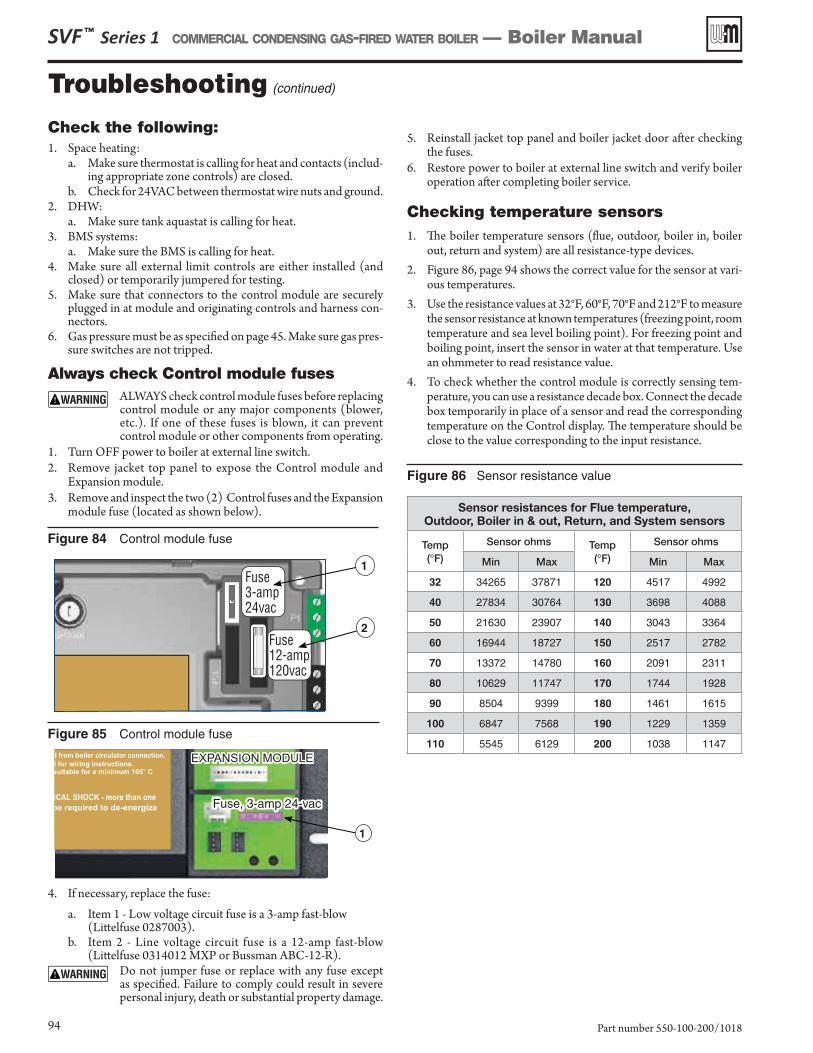
Troubleshooting (continued)
1
1
2
SVF ™ Series 1 COMMERCIAL CONDENSING GAS-FIRED WATER BOILER — Boiler Manual
Part number 550-100-200/101894
Check the following:1. Space heating:
a. Make sure thermostat is calling for heat and contacts (includ-ing appropriate zone controls) are closed.
b. Check for 24VAC between thermostat wire nuts and ground.2. DHW:
a. Make sure tank aquastat is calling for heat.3. BMS systems:
a. Make sure the BMS is calling for heat.4. Make sure all external limit controls are either installed (and
closed) or temporarily jumpered for testing.5. Make sure that connectors to the control module are securely
plugged in at module and originating controls and harness con-nectors.
6. Gas pressure must be as specified on page 45. Make sure gas pres-sure switches are not tripped.
Always check Control module fusesALWAYS check control module fuses before replacing control module or any major components (blower, etc.). If one of these fuses is blown, it can prevent control module or other components from operating.
1. Turn OFF power to boiler at external line switch.2. Remove jacket top panel to expose the Control module and
Expansion module.3. Remove and inspect the two (2) Control fuses and the Expansion
module fuse (located as shown below).
Figure 84 Control module fuse
Figure 85 Control module fuse
Figure 86 Sensor resistance value
5. Reinstall jacket top panel and boiler jacket door after checking the fuses.
6. Restore power to boiler at external line switch and verify boiler operation after completing boiler service.
Checking temperature sensors1. The boiler temperature sensors (flue, outdoor, boiler in, boiler
out, return and system) are all resistance-type devices.2. Figure 86, page 94 shows the correct value for the sensor at vari-
ous temperatures.3. Use the resistance values at 32°F, 60°F, 70°F and 212°F to measure
the sensor resistance at known temperatures (freezing point, room temperature and sea level boiling point). For freezing point and boiling point, insert the sensor in water at that temperature. Use an ohmmeter to read resistance value.
4. To check whether the control module is correctly sensing tem-perature, you can use a resistance decade box. Connect the decade box temporarily in place of a sensor and read the corresponding temperature on the Control display. The temperature should be close to the value corresponding to the input resistance.
4. If necessary, replace the fuse:a. Item 1 - Low voltage circuit fuse is a 3-amp fast-blow
(Littelfuse 0287003).b. Item 2 - Line voltage circuit fuse is a 12-amp fast-blow
(Littelfuse 0314012 MXP or Bussman ABC-12-R).Do not jumper fuse or replace with any fuse except as specified. Failure to comply could result in severe personal injury, death or substantial property damage.
Sensor resistances for Flue temperature, Outdoor, Boiler in & out, Return, and System sensors
Temp (°F)
Sensor ohms Temp (°F)
Sensor ohms
Min Max Min Max
32 34265 37871 120 4517 4992
40 27834 30764 130 3698 4088
50 21630 23907 140 3043 3364
60 16944 18727 150 2517 2782
70 13372 14780 160 2091 2311
80 10629 11747 170 1744 1928
90 8504 9399 180 1461 1615
100 6847 7568 190 1229 1359
110 5545 6129 200 1038 1147
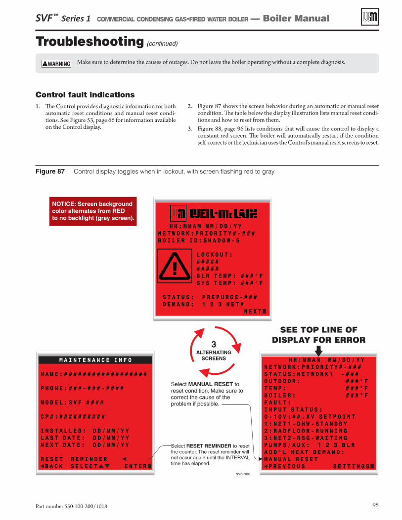
Troubleshooting (continued)
SVF ™ Series 1 COMMERCIAL CONDENSING GAS-FIRED WATER BOILER — Boiler Manual
Part number 550-100-200/1018 95
Control fault indications1. The Control provides diagnostic information for both
automatic reset conditions and manual reset condi-tions. See Figure 53, page 66 for information available on the Control display.
2. Figure 87 shows the screen behavior during an automatic or manual reset condition. The table below the display illustration lists manual reset condi-tions and how to reset from them.
3. Figure 88, page 96 lists conditions that will cause the control to display a constant red screen. The boiler will automatically restart if the condition self-corrects or the technician uses the Control’s manual reset screens to reset.
Figure 87 Control display toggles when in lockout, with screen flashing red to gray
Make sure to determine the causes of outages. Do not leave the boiler operating without a complete diagnosis.
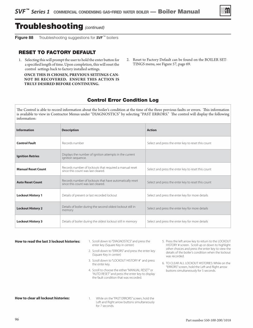
Troubleshooting (continued)
SVF ™ Series 1 COMMERCIAL CONDENSING GAS-FIRED WATER BOILER — Boiler Manual
Part number 550-100-200/101896
How to read the last 3 lockout histories: 1. Scroll down to “DIAGNOSTICS” and press the
enter key (Square Key in center)
2. Scroll down to “ERRORS” and press the enter key
(Square Key in center)
3. Scroll down to “LOCKOUT HISTORY #” and press
the enter key.
4. Scroll to choose the either “MANUAL RESET” or
“AUTO RESET” and press the enter key to display
the fault condition that was recorded.
5. Press the left arrow key to return to the LOCKOUT
HISTORY # screen. Scroll up or down to highlight
other choices and press the enter key to view the
details of the boiler’s condition when the lockout
was recorded.
6. TO CLEAR ALL LOCKOUT HISTORIES: While on the
“ERRORS” screen, hold the Left and Right arrow
buttons simultaneously for 5 seconds.
Control Error Condition Log
The Control is able to record information about the boiler’s condition at the time of the three previous faults or errors. This information is available to view in Contractor Menus under “DIAGNOSTICS” by selecting “PAST ERRORS.” The control will display the following information:
Information Description Action
Control Fault Records number Select and press the enter key to reset this count
Ignition RetriesDisplays the number of ignition attempts in the current ignition sequence.
Manual Reset CountRecords number of lockouts that required a manual reset since this count was last cleared.
Select and press the enter key to reset this count
Auto Reset CountRecords number of lockouts that have automatically reset since this count was last cleared.
Select and press the enter key to reset this count
Lockout History 1 Details of present or last recorded lockout Select and press the enter key for more details
Lockout History 2Details of boiler during the second oldest lockout still in memory
Select and press the enter key for more details
Lockout History 3 Details of boiler during the oldest lockout still in memory Select and press the enter key for more details
Figure 88 Troubleshooting suggestions for SVF TM boilers
RESET TO FACTORY DEFAULT1. Selecting this will prompt the user to hold the enter button for
a specified length of time. Upon completion, this will reset the control settings back to factory installed settings.ONCE THIS IS CHOSEN, PREVIOUS SETTINGS CAN-NOT BE RECOVERED. ENSURE THIS ACTION IS TRULY DESIRED BEFORE CONTINUING.
2. Reset to Factory Default can be found on the BOILER SET-TINGS menu, see Figure 57, page 69.
How to clear all lockout histories: 1. While on the “PAST ERRORS” screen, hold the
Left and Right arrow buttons simultaneously
for 7 seconds.
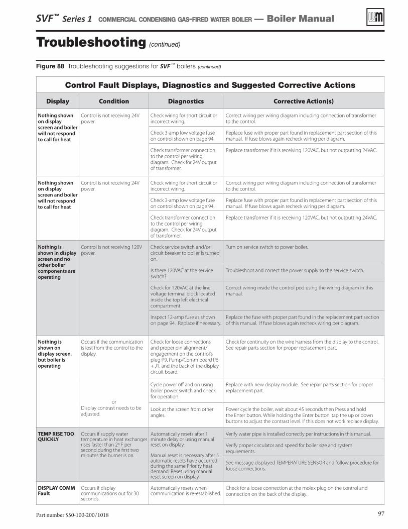
Troubleshooting (continued)
SVF ™ Series 1 COMMERCIAL CONDENSING GAS-FIRED WATER BOILER — Boiler Manual
Part number 550-100-200/1018 97
Control Fault Displays, Diagnostics and Suggested Corrective Actions
Display Condition Diagnostics Corrective Action(s)
Nothing shown on display screen and boiler will not respond to call for heat
Control is not receiving 24V
power.
Check wiring for short circuit or
incorrect wiring.
Correct wiring per wiring diagram including connection of transformer
to the control.
Check 3-amp low voltage fuse
on control shown on page 94.
Replace fuse with proper part found in replacement part section of this
manual. If fuse blows again recheck wiring per diagram.
Check transformer connection
to the control per wiring
diagram. Check for 24V output
of transformer.
Replace transformer if it is receiving 120VAC, but not outputting 24VAC.
Nothing is shown in display screen and no other boiler components are operating
Control is not receiving 120V
power.
Check service switch and/or
circuit breaker to boiler is turned
on.
Turn on service switch to power boiler.
Is there 120VAC at the service
switch?
Troubleshoot and correct the power supply to the service switch.
Check for 120VAC at the line
voltage terminal block located
inside the top left electrical
compartment.
Correct wiring inside the control pod using the wiring diagram in this
manual.
Inspect 12-amp fuse as shown
on page 94. Replace if necessary.
Replace the fuse with proper part found in the replacement part section
of this manual. If fuse blows again recheck wiring per diagram.
Nothing is shown on display screen, but boiler is operating
Occurs if the communication
is lost from the control to the
display.
or
Display contrast needs to be
adjusted.
Check for loose connections
and proper pin alignment/
engagement on the control's
plug P9, Pump/Comm board P6
+ J1, and the back of the display
circuit board.
Check for continuity on the wire harness from the display to the control.
See repair parts section for proper replacement part.
Cycle power off and on using
boiler power switch and check
for operation.
Replace with new display module. See repair parts section for proper
replacement part.
Look at the screen from other
angles.
Power cycle the boiler, wait about 45 seconds then Press and hold
the Enter button. While holding the Enter button, tap the up or down
buttons to adjust the contrast level. If this does not work replace display.
TEMP RISE TOO QUICKLY
Occurs if supply water temperature in heat exchanger rises faster than 2º F per second during the first two minutes the burner is on.
Automatically resets after 1 minute delay or using manual reset on display. Manual reset is necessary after 5 automatic resets have occurred during the same Priority heat demand. Reset using manual reset screen on display.
Verify water pipe is installed correctly per instructions in this manual.
Verify proper circulator and speed for boiler size and system
requirements.
See message displayed TEMPERATURE SENSOR and follow procedure for
loose connections.
DISPLAY COMM Fault
Occurs if display communications out for 30 seconds.
Automatically resets when communication is re-established.
Check for a loose connection at the molex plug on the control and
connection on the back of the display.
Figure 88 Troubleshooting suggestions for SVF TM boilers (continued)
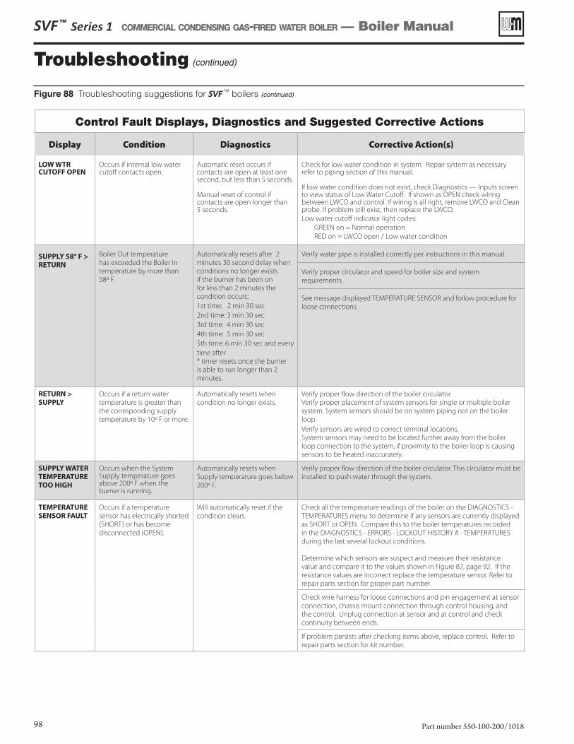
Troubleshooting (continued)
SVF ™ Series 1 COMMERCIAL CONDENSING GAS-FIRED WATER BOILER — Boiler Manual
Part number 550-100-200/101898
Control Fault Displays, Diagnostics and Suggested Corrective Actions
Display Condition Diagnostics Corrective Action(s)
LOW WTR CUTOFF OPEN
Occurs if internal low water cutoff contacts open.
Automatic reset occurs if contacts are open at least one second, but less than 5 seconds.
Manual reset of control if contacts are open longer than 5 seconds.
Check for low water condition in system. Repair system as necessary refer to piping section of this manual. If low water condition does not exist, check Diagnostics — Inputs screen to view status of Low Water Cutoff. If shown as OPEN check wiring between LWCO and control. If wiring is all right, remove LWCO and Clean probe. If problem still exist, then replace the LWCO.
Low water cutoff indicator light codes:
GREEN on = Normal operation
RED on = LWCO open / Low water condition
SUPPLY 58° F >
RETURN
Boiler Out temperature
has exceeded the Boiler In
temperature by more than
58º F.
Automatically resets after 2
minutes 30 second delay when
conditions no longer exists.
If the burner has been on
for less than 2 minutes the
condition occurs:
1st time: 2 min 30 sec
2nd time: 3 min 30 sec
3rd time: 4 min 30 sec
4th time: 5 min 30 sec
5th time: 6 min 30 sec and every
time after
* timer resets once the burner
is able to run longer than 2
minutes.
Verify water pipe is installed correctly per instructions in this manual.
Verify proper circulator and speed for boiler size and system
requirements.
See message displayed TEMPERATURE SENSOR and follow procedure for
loose connections.
RETURN >
SUPPLY
Occurs if a return water
temperature is greater than
the corresponding supply
temperature by 10º F or more.
Automatically resets when
condition no longer exists.
Verify proper flow direction of the boiler circulator.
Verify proper placement of system sensors for single or multiple boiler
system. System sensors should be on system piping not on the boiler
loop.
Verify sensors are wired to correct terminal locations.
System sensors may need to be located further away from the boiler
loop connection to the system, if proximity to the boiler loop is causing
sensors to be heated inaccurately.
SUPPLY WATER
TEMPERATURE
TOO HIGH
Occurs when the System Supply temperature goes above 200º F when the burner is running.
Automatically resets when
Supply temperature goes below
200º F.
Verify proper flow direction of the boiler circulator. This circulator must be
installed to push water through the system.
TEMPERATURE
SENSOR FAULT
Occurs if a temperature
sensor has electrically shorted
(SHORT) or has become
disconnected (OPEN).
Will automatically reset if the
condition clears.
Check all the temperature readings of the boiler on the DIAGNOSTICS -
TEMPERATURES menu to determine if any sensors are currently displayed
as SHORT or OPEN. Compare this to the boiler temperatures recorded
in the DIAGNOSTICS - ERRORS - LOCKOUT HISTORY # - TEMPERATURES
during the last several lockout conditions.
Determine which sensors are suspect and measure their resistance
value and compare it to the values shown in Figure 82, page 92. If the
resistance values are incorrect replace the temperature sensor. Refer to
repair parts section for proper part number.
Check wire harness for loose connections and pin engagement at sensor
connection, chassis mount connection through control housing, and
the control. Unplug connection at sensor and at control and check
continuity between ends.
If problem persists after checking items above, replace control. Refer to
repair parts section for kit number.
Figure 88 Troubleshooting suggestions for SVF TM boilers (continued)
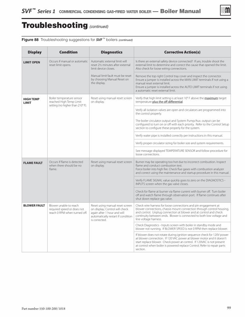
SVF ™ Series 1 COMMERCIAL CONDENSING GAS-FIRED WATER BOILER — Boiler Manual
Part number 550-100-200/1018 99
Troubleshooting (continued)
Figure 88 Troubleshooting suggestions for SVF TM boilers (continued)
Display Condition Diagnostics Corrective Action(s)
LIMIT OPEN Occurs if manual or automatic
reset limit opens.
Automatic external limit will
reset 2½ minutes after external
limit device closes.
Manual limit fault must be reset
by choosing Manual Reset on
the display.
Is there an external safety device connected? If yes, trouble shoot the
external limit to determine and correct the cause that opened the limit.
Also check for loose wiring connections.
Remove the top right Control tray cover and inspect the connector.
Ensure a jumper is installed across the MAN LIMIT terminals if not using a
manual reset external limit.
Ensure a jumper is installed across the AUTO LIMIT terminals if not using
a automatic reset external limit.
HIGH TEMP
LIMIT
Boiler temperature sensor
reached High Temp Limit
setting (no higher than 210° F).
Reset using manual reset screen
on display.
Verify that high limit setting is at least 10° F above the maximum target
temperature plus the off differential.
Verify all isolation valves are open and circulators are programmed into
the control properly.
The boiler circulator output and System Pump/Aux. output can be
configured to turn on or off with each priority. Refer to the Control Setup
section to configure these properly for the system.
Verify water pipe is installed correctly per instructions in this manual.
Verify proper circulator sizing for boiler size and system requirements.
See message displayed TEMPERATURE SENSOR and follow procedure for
loose connections.
FLAME FAULT Occurs if flame is detected
when there should be no
flame.
Reset using manual reset screen
on display.
Burner may be operating too hot due to incorrect combustion. Inspect
flame and conduct combustion test.
Force boiler into high fire. Check flue gases with combustion analyzer
and correct using the maintenance and startup procedure in this manual.
Verify FLAME SIGNAL value quickly goes to zero on the DIAGNOSTICS -
INPUTS screen when the gas valve closes.
Check for flame at burner via flame current with burner off. Turn boiler
off and watch flame through observation port. If flame continues after
shut down replace gas valve.
BLOWER FAULT Blower unable to reach
required speed or does not
reach 0 RPM when turned off.
Reset using manual reset screen
on display; Control will check
again after 1 hour and will
automatically restart if condition
is corrected.
Check wire harness for loose connections and pin engagement at blower connections, chassis mount connection through control housing, and control. Unplug connection at blower and at control and check continuity between ends. Blower is connected to both low voltage and line voltage harness.
Check Diagnostics - Inputs screen with boiler in standby mode and
blower not running. If BLOWER SPEED is not 0 RPM then replace blower.
If blower does not rotate during ignition sequence check for 120V power
at blower connection. If 120 VAC power at blower motor and it doesn't
start replace blower. Check power at control. If 120VAC is not present
at control when boiler is powered replace Control. Refer to repair parts
section.
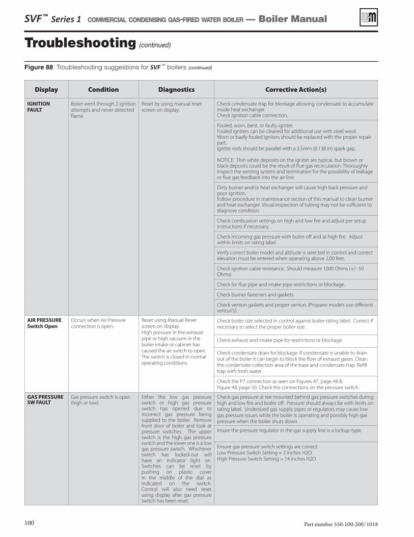
SVF ™ Series 1 COMMERCIAL CONDENSING GAS-FIRED WATER BOILER — Boiler Manual
Part number 550-100-200/1018100
Troubleshooting (continued)
Figure 88 Troubleshooting suggestions for SVF TM boilers (continued)
Display Condition Diagnostics Corrective Action(s)
IGNITION
FAULT
Boiler went through 2 ignition
attempts and never detected
flame.
Reset by using manual reset
screen on display.
Check condensate trap for blockage allowing condensate to accumulate inside heat exchanger.Check ignition cable connection.
Fouled, worn, bent, or faulty igniter. Fouled igniters can be cleaned for additional use with steel wool. Worn or badly fouled igniters should be replaced with the proper repair part. Igniter rods should be parallel with a 3.5mm (0.138 in) spark gap.
NOTICE: Thin white deposits on the igniter are typical, but brown or black deposits could be the result of flue gas recirculation. Thoroughly inspect the venting system and termination for the possibility of leakage or flue gas feedback into the air line.
Dirty burner and/or heat exchanger will cause high back pressure and poor ignition. Follow procedure in maintenance section of this manual to clean burner and heat exchanger. Visual inspection of tubing may not be sufficient to diagnose condition.
Check combustion settings on high and low fire and adjust per setup instructions if necessary.
Check incoming gas pressure with boiler off and at high fire. Adjust within limits on rating label.
Verify correct boiler model and altitude is selected in control and correct elevation must be entered when operating above 2,00 feet.
Check ignition cable resistance. Should measure 1000 Ohms (+/- 50 Ohms).
Check for flue pipe and intake pipe restrictions or blockage.
Check burner fasteners and gaskets.
Check venturi gaskets and proper venturi. (Propane models use different venturi’s).
AIR PRESSURE
Switch Open
Occurs when Air Pressure
connection is open.
Reset using Manual Reset
screen on display.
High pressure in the exhaust
pipe or high vacuum in the
boiler intake or cabinet has
caused the air switch to open.
The switch is closed in normal
operating conditions.
Check boiler size selected in control against boiler rating label. Correct if
necessary to select the proper boiler size.
Check exhaust and intake pipe for restrictions or blockage.
Check condensate drain for blockage. If condensate is unable to drain
out of the boiler it can begin to block the flow of exhaust gases. Clean
the condensate collection area of the base and condensate trap. Refill
trap with fresh water.
Check the P7 connection as seen on Figures 47, page 48 &
Figure 48, page 50. Check the connections on the pressure switch.
GAS PRESSURE SW FAULT
Gas pressure switch is open (high or low).
Either the low gas pressure switch or high gas pressure switch has opened due to incorrect gas pressure being supplied to the boiler. Remove front door of boiler and look at pressure switches. The upper switch is the high gas pressure switch and the lower one is a low gas pressure switch. Whichever switch has locked-out will have an indicator light on. Switches can be reset by pushing on plastic cover in the middle of the dial as indicated on the switch. Control will also need reset using display after gas pressure switch has been reset.
Check gas pressure at tee mounted behind gas pressure switches during
high and low fire and boiler off. Pressure should always be with limits on
rating label. Undersized gas supply pipes or regulators may cause low
gas pressure issues while the boiler is operating and possibly high gas
pressure when the boiler shuts down.
Insure the pressure regulator in the gas supply line is a lockup-type.
Ensure gas pressure switch settings are correct.
Low Pressure Switch Setting = 2 inches H2O
High Pressure Switch Setting = 14 inches H2O
SVF ™ Series 1 COMMERCIAL CONDENSING GAS-FIRED WATER BOILER — Boiler Manual
Part number 550-100-200/1018 101
Display Condition Diagnostics Corrective Action(s)
MINIMUM AIR FLOW SWITCH FAULT
Min air flow switch is open when it should be closed, or closed when it should be open.
Switch should close when the blower passes enough air.Manual reset is required.
Check blower is operating correctly.
Check to see if switch is not stuck open/closed.
Check hose connection to switch for disconnect or damaged.
Check wiring connections are firmly connected and not damaged.
Check if Combustion Air Pressure Kit has been installed.
Check sense line connections.
Check electrical wiring.
Check to see if switch is stuck open/closed.
HW FAULT EXPANSION BRD
Expansion Control Board hardware has failed.
Expansion Control Board has detected an issue with it’s hardware and has locked out. Requires a manual reset.
Check boiler size selected in Control against boiler rating label. Correct if
necessary to select the proper boiler size.
GV FAULT EXPANSION BRD
Gas valve output of the Expansion module.
Expansion Control Board has detected an issue with the gas valve circuit. Requires a manual reset.
Check the wire harnesses between the Control, Expansion module, and
gas valve.
EXP BOARD COM FAULT
Expansion Control Board communication fault.
Communication has been lost between the Control and the Expansion Control Board.
Check the communication wire harness between the two controls.
Hardware Fault Occurs when micro-controllers on main board have a RAM or ROM error, or communication is cut off.
Check for hardware damages. RAM or ROM errors can be reset with the manual reset option.
If problems persist, replace main board.
Hardware Fault 1,2,3,4
The control has detected a problem with its gas valve output circuit.
Auto reset if condition is clear after lockout, then 1 hour automatic reset if condition clear, then manual reset required.
Check for physical damages.
Check connections to gas valve and gas pressure.
If problem persists, replace main board.
ClosureSwitch Fault
Closure switch connections on P7 Pins 2 and 3 are open for more than 4 minutes.
Soft lockout when 4 minute timer expires. Reset when closure is made.
None – Check jumper on correct pins and secure connection.
Flow switch attached – Check correct pump is on, check wiring to flow
switch, and check switch is closing.
CAD – Check voltage to damper. Check damper is opening.
OUTDOOR
SENSOR ERROR
Outdoor temperature sensor short or OPEN.
Will automatically reset if the condition clears.
Warning only. Supply Max is targeted until ODT is restored, if used for target adjustment.
Determine which sensors are suspect and measure their resistance value and compare it to the values shown in Figure 86, page 94. If the resistance values are incorrect replace the temperature sensor. Refer to repair parts section for proper part number.
Check wire harness for loose connections and pin engagement at sensor connection, chassis mount connection through control housing, and the control. Unplug connection at sensor and at control and check continuity between ends.
If problem persists after checking items above, replace control. Refer to repair parts section for kit number.
Flue Temp Too High
Occurs if flue temperature sensor exceeds 210°F (Warning) or 220°F (Lockout).
Automatic reset occurs if temperature drops below 210°F for 2 ½ minutes.
Manual reset is required if the temperature rises above 220°F. Reset using manual reset screen on display.
Follow procedure above for SHORT and OPEN sensor conditions to properly diagnose sensor. In addition inspect heat exchanger combustion chamber and flue-ways for abnormal wear and buildup.
Inspect vent system for abnormal wear or damage.
Contact Weil-McLain Technical Support.
Figure 88 Troubleshooting suggestions for SVF TM boilers (continued)
Troubleshooting (continued)
MaintenanceDisconnect power before servicing
Electrical shock hazard — Disconnect all electrical power to the boiler before attempting maintenance procedures. Failure to complete could result in severe personal injury, death or substantial property damage.
Perform startup and check/out
Removing and reinstalling components can change boiler behavior.
After any maintenance procedure, you must verify operation after servicing. To do so, follow the complete procedure for boiler and system startup, beginning on page 79. Failure to comply could result in severe per-sonal injury, death or substantial property damage.
Label all wires prior to disconnection when serving controls. Wiring errors can cause improper and danger-ous operation.
General maintenance1. Oil motors in system requiring regular oiling.2. See Oiled bearing pumps for motor oiling procedures.
Oiled-bearing pumps1. Check pumps in the system. Oil any pumps requiring oil, follow-
ing pump manufacturer’s instructions. Over-oiling will damage the pump.
Clean the heat exchanger when required — water side1. In order for the efficiency of boilers to increase beyond the con-
densing limit, new materials have been introduced for the heat exchanger, including stainless steel.
2. Stainless steel has excellent heat transfer characteristics and is light in weight.
3. These new materials also require cleaning solutions that differ from those used in conventional cast iron and steel boilers.
One common cleaning method that CANNOT be used with systems containing stainless steel is a solution of trisodium phosphate, commonly referred to as “TSP.”
Weil-McLain recommends Sentinel X400 for cleaning boiler. See the Replacement Parts section at the end of this manual for ordering information.
Clean the heat exchanger when required — flue side1. Shut down boiler:
a. Follow “To Turn Off Gas to Appliance” instructions on boiler and Lighting instructions.
b. Do not drain boiler unless it will be exposed to freezing temperatures. If using freeze prevention fluid in system, do not drain.
2. Allow time for boiler to cool to room temperature if it has been firing.
Remove heat exchanger cover plate and burner1. Close the external manual gas valve.2. Disconnect all power to the boiler.3. Allow the boiler to cool if it has been operating.4. Follow the procedure on page 90 (steps 1-14) to remove the
burner and access the heat exchanger.
Water spray the heat exchanger
1. Disconnect the condensate line at the bottom of the heat ex-changer so debris will not clog the trap.a. Loosen the ferrule nut and remove the condensate drain
outlet.b. Place a pan under condensate drain outlet to collect water
and any debris.2. Use the combustion chamber openings at either end to spray
water down into the heat exchanger tubes. Continue spraying until all debris in the tubes has been flushed into the base.a. Spray water into the flue sampling opening to flush remaining
sediment to the condensate outlet.b. Spray water through the condensate line to clean it thor-
oughly.c. Remove the pan and re-install the condensate line.d. Re-install the flue sampling cap.
Inspect cover plate / burner gasketInspect the cover plate/burner gasket. Replace if damaged.
Re-install burner Follow the procedure on page 90 (steps 15-27) to re-install the burner and burner/cover plate gasket.
SVF ™ Series 1 COMMERCIAL CONDENSING GAS-FIRED WATER BOILER — Boiler Manual
Part number 550-100-200/1018102
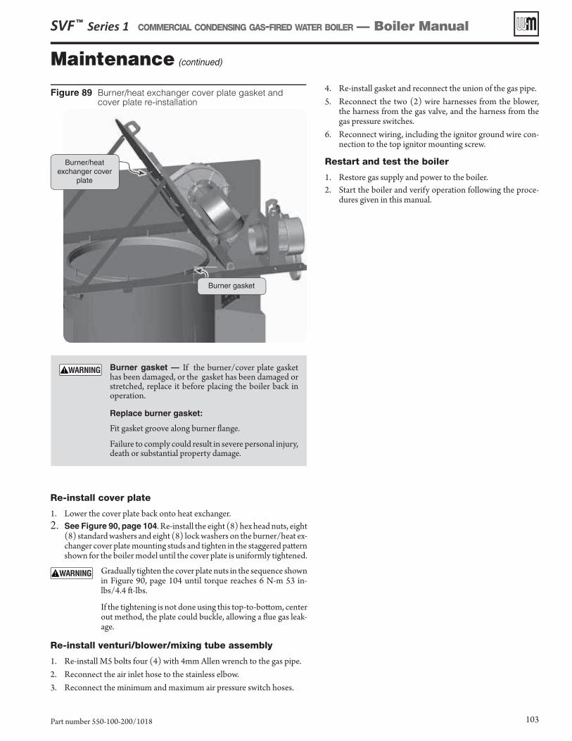
Maintenance (continued)
SVF ™ Series 1 COMMERCIAL CONDENSING GAS-FIRED WATER BOILER — Boiler Manual
Part number 550-100-200/1018 103
Re-install cover plate
1. Lower the cover plate back onto heat exchanger.2. See Figure 90, page 104. Re-install the eight (8) hex head nuts, eight
(8) standard washers and eight (8) lock washers on the burner/heat ex-changer cover plate mounting studs and tighten in the staggered patt ern shown for the boiler model until the cover plate is uniformly tightened.
Gradually tighten the cover plate nuts in the sequence shown in Figure 90, page 104 until torque reaches 6 N-m 53 in-lbs/4.4 ft -lbs.
If the tightening is not done using this top-to-bott om, center out method, the plate could buckle, allowing a fl ue gas leak-age.
Re-install venturi/blower/mixing tube assembly
1. Re-install M5 bolts four (4) with 4mm Allen wrench to the gas pipe.2. Reconnect the air inlet hose to the stainless elbow.3. Reconnect the minimum and maximum air pressure switch hoses.
Figure 89 Burner/heat exchanger cover plate gasket and cover plate re-installation
Burner/heat exchanger cover
plate
Burner gasket
Burner gasket — If the burner/cover plate gasket has been damaged, or the gasket has been damaged or stretched, replace it before placing the boiler back in operation.
Replace burner gasket:
Fit gasket groove along burner fl ange.
Failure to comply could result in severe personal injury, death or substantial property damage.
4. Re-install gasket and reconnect the union of the gas pipe.5. Reconnect the two (2) wire harnesses from the blower,
the harness from the gas valve, and the harness from the gas pressure switches.
6. Reconnect wiring, including the ignitor ground wire con-nection to the top ignitor mounting screw.
Restart and test the boiler
1. Restore gas supply and power to the boiler.2. Start the boiler and verify operation following the proce-
dures given in this manual.
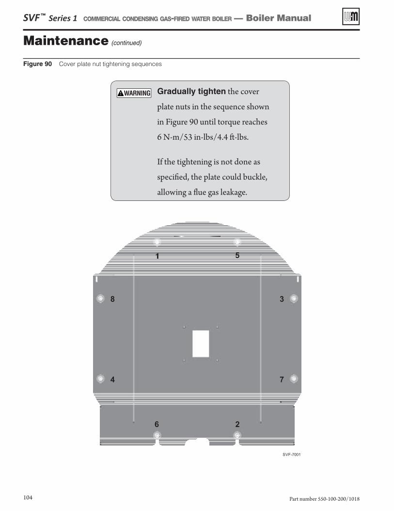
Maintenance (continued)
Figure 90 Cover plate nut tightening sequences
SVF ™ Series 1 COMMERCIAL CONDENSING GAS-FIRED WATER BOILER — Boiler Manual
Part number 550-100-200/1018104
Gradually tighten the cover
plate nuts in the sequence shown
in Figure 90 until torque reaches
6 N-m/53 in-lbs/4.4 ft-lbs.
If the tightening is not done as
specified, the plate could buckle,
allowing a flue gas leakage.
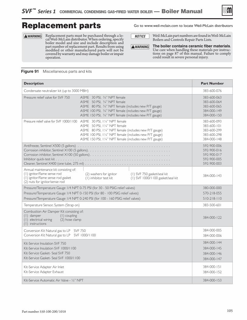
Replacement parts
Figure 91 Miscellaneous parts and kits
Go to www.weil-mclain.com to locate Weil-McLain distributors
Replacement parts must be purchased through a lo-cal Weil-McLain distributor. When ordering, specify boiler model and size and include description and part number of replacement part. Results from using modified or other manufactured parts will not be covered by warranty and may damage boiler or impair operation.
Weil-McLain part numbers are found in Weil-McLain Boilers and Controls Repair Parts Lists.
The boiler contains ceramic fiber materials. Use care when handling these materials per instruc-tions on page 87 of this manual. Failure to comply could result in severe personal injury.
SVF ™ Series 1 COMMERCIAL CONDENSING GAS-FIRED WATER BOILER — Boiler Manual
Part number 550-100-200/1018 105
Description Part Number
Condensate neutralizer kit (up to 3000 MBH) 383-600-076
Pressure relief valve for SVF 750 ASME 30 PSI, ¾” NPT female
ASME 50 PSI, ¾” NPT female
ASME 80 PSI, ¾” NPT female (includes new P/T gauge)
ASME 100 PSI, ¾” NPT female (includes new P/T gauge)
ASME 150 PSI, ¾” NPT female (includes new P/T gauge)
383-600-063
383-600-064
383-600-065
384-000-149
384-000-150
Pressure relief valve for SVF 1000/1100 ASME 30 PSI, 1¼” NPT female
ASME 50 PSI, 1¼” NPT female
ASME 80 PSI, 1¼” NPT female (includes new P/T gauge)
ASME 100 PSI, 1¼” NPT female (includes new P/T gauge)
ASME 150 PSI, 1¼” NPT female (includes new P/T gauge)
383-600-093
383-600-101
383-600-299
383-600-298
384-000-148
Antifreeze, Sentinel X500 (5 gallons) . . . . . . . . . . . . . . . . . . . . . . . . . . . . . . . . . . . . . .
Corrosion inhibitor, Sentinel X100 (5 gallons). . . . . . . . . . . . . . . . . . . . . . . . . . . . . . . . . .
Corrosion inhibitor, Sentinel X100 (50 gallons) . . . . . . . . . . . . . . . . . . . . . . . . . . . . . . . . .
Inhibitor quick-test kit . . . . . . . . . . . . . . . . . . . . . . . . . . . . . . . . . . . . . . . . . . . . . . .
Cleaner, Sentinel X400 (one tube, 275 ml) . . . . . . . . . . . . . . . . . . . . . . . . . . . . . . . . . . .
592-900-006
592-900-016
592-900-017
592-900-005
592-900-003
Annual maintenance kit consisting of:(1) ignitor/flame sense rod(1) ignitor/flame sense rod gasket(2) nuts for ignitor/sense rod
384-000-143(2) washers for ignitor(1) inhibitor test kit
(1) SVF 750 gasket/seal kit (1) SVF 1000/1100 gasket/seal kit
Pressure/Temperature Gauge 1/4 NPT 0-75 PSI (for 30 - 50 PSIG relief valves)
Pressure/Temperature Gauge 1/4 NPT 0-150 PSI (for 80 - 100 PSIG relief valves)
Pressure/Temperature Gauge 1/4 NPT 0-240 PSI (for 100 - 160 PSIG relief valves)
380-000-000
570-218-055
510-218-110
Temperature Sensor, System (Strap on) 383-500-601
Combustion Air Damper Kit consisting of:(1) damper (1) coupling (1) electrical wiring (2) hose clamp (1) instructions
384-000-122
Conversion Kit Natural gas to LP SVF 750
Conversion Kit Natural gas to LP SVF 1000/1100
384-000-005
384-000-006
Kit-Service Insulation SVF 750
Kit-Service Insulation SVF 1000/1100
Kit-Service Gasket- Seal SVF 750
Kit-Service Gasket- Seal SVF 1000/1100
384-000-144
384-000-145
384-000-146
384-000-147
Kit-Service Adapter Air Inlet
Kit-Service Adapter Exhaust
384-000-151
384-000-152
Kit-Service Automatic Air Valve - ½” NPT 384-000-153
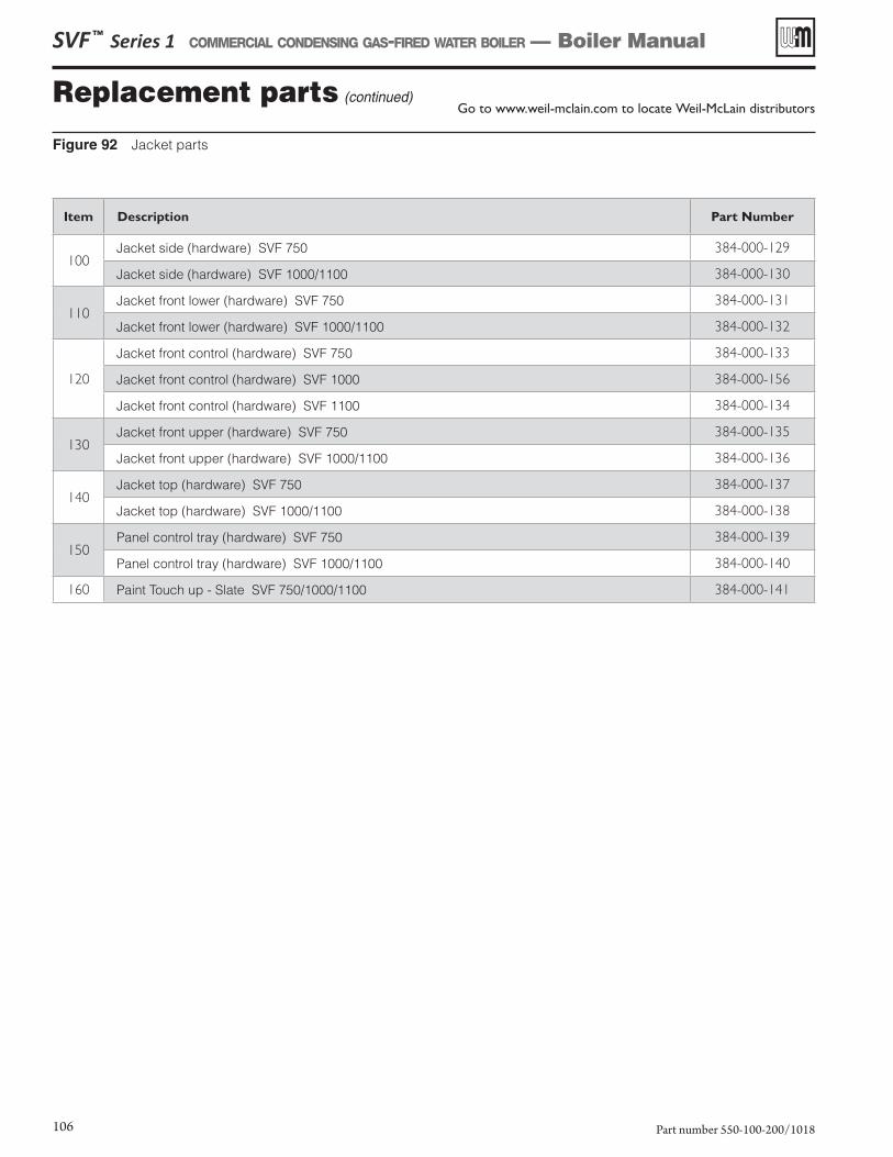
Replacement parts (continued)
Figure 92 Jacket parts
Go to www.weil-mclain.com to locate Weil-McLain distributors
SVF ™ Series 1 COMMERCIAL CONDENSING GAS-FIRED WATER BOILER — Boiler Manual
Part number 550-100-200/1018106
Item Description Part Number
100Jacket side (hardware) SVF 750 384-000-129
Jacket side (hardware) SVF 1000/1100 384-000-130
110Jacket front lower (hardware) SVF 750 384-000-131
Jacket front lower (hardware) SVF 1000/1100 384-000-132
120
Jacket front control (hardware) SVF 750 384-000-133
Jacket front control (hardware) SVF 1000 384-000-156
Jacket front control (hardware) SVF 1100 384-000-134
130Jacket front upper (hardware) SVF 750 384-000-135
Jacket front upper (hardware) SVF 1000/1100 384-000-136
140Jacket top (hardware) SVF 750 384-000-137
Jacket top (hardware) SVF 1000/1100 384-000-138
150Panel control tray (hardware) SVF 750 384-000-139
Panel control tray (hardware) SVF 1000/1100 384-000-140
160 Paint Touch up - Slate SVF 750/1000/1100 384-000-141
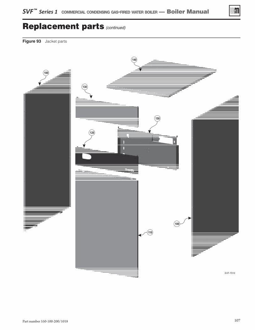
Replacement parts (continued)
Figure 93 Jacket parts
SVF ™ Series 1 COMMERCIAL CONDENSING GAS-FIRED WATER BOILER — Boiler Manual
Part number 550-100-200/1018 107
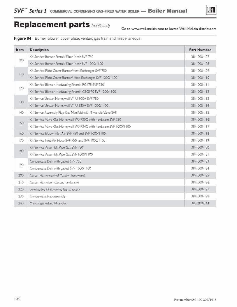
Replacement parts (continued)Go to www.weil-mclain.com to locate Weil-McLain distributors
SVF ™ Series 1 COMMERCIAL CONDENSING GAS-FIRED WATER BOILER — Boiler Manual
Part number 550-100-200/1018108
Figure 94 Burner, blower, cover plate, venturi, gas train and miscellaneous
Item Description Part Number
100Kit-Service Burner-Premix Fiber-Mesh SVF 750 384-000-107
Kit-Service Burner-Premix Fiber-Mesh SVF 1000/1100 384-000-108
110Kit-Service Plate-Cover Burner/Heat Exchanger SVF 750 384-000-109
Kit-Service Plate-Cover Burner/ Heat Exchanger SVF 1000/1100 384-000-110
120Kit-Service Blower Modulating Premix RG175 SVF 750 384-000-111
Kit-Service Blower Modulating Premix G1G170 SVF 1000/1100 384-000-112
130Kit-Servce Venturi Honeywell VMU 300A SVF 750 384-000-113
Kit-Servce Venturi Honeywell VMU 335A SVF 1000/1100 384-000-114
140 Kit-Servce Assembly Pipe Gas Manifold with T-Handle Valve SVF 384-000-115
150Kit-Service Valve-Gas Honeywell VR4730C with hardware SVF 750 384-000-116
Kit-Service Valve-Gas Honeywell VR4734C with hardware SVF 1000/1100 384-000-117
160 Kit-Service Elbow-Inlet Air SVF 750 and SVF 1000/1100 384-000-118
170 Kit-Service Inlet-Air Hose SVF 750 and SVF 1000/1100 384-000-119
180Kit-Service Assembly Pipe Gas SVF 750 384-000-120
Kit-Service Assembly Pipe Gas SVF 1000/1100 384-000-121
190Condensate Dish with gasket SVF 750 384-000-123
Condensate Dish with gasket SVF 1000/1100 384-000-124
200 Caster kit, non-swivel (Caster, hardware) 384-000-125
210 Caster kit, swivel (Caster, hardware) 384-000-126
220 Leveling leg kit (Leveling leg, adapter) 384-000-127
230 Condensate trap assembly 384-000-128
240 Manual gas valve, T-Handle 383-600-244
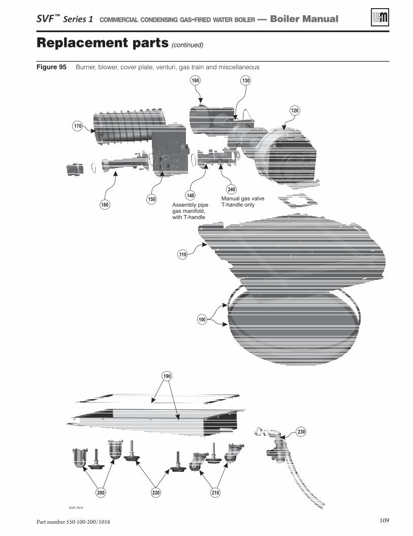
Figure 95 Burner, blower, cover plate, venturi, gas train and miscellaneous
Replacement parts (continued)
SVF ™ Series 1 COMMERCIAL CONDENSING GAS-FIRED WATER BOILER — Boiler Manual
Part number 550-100-200/1018 109
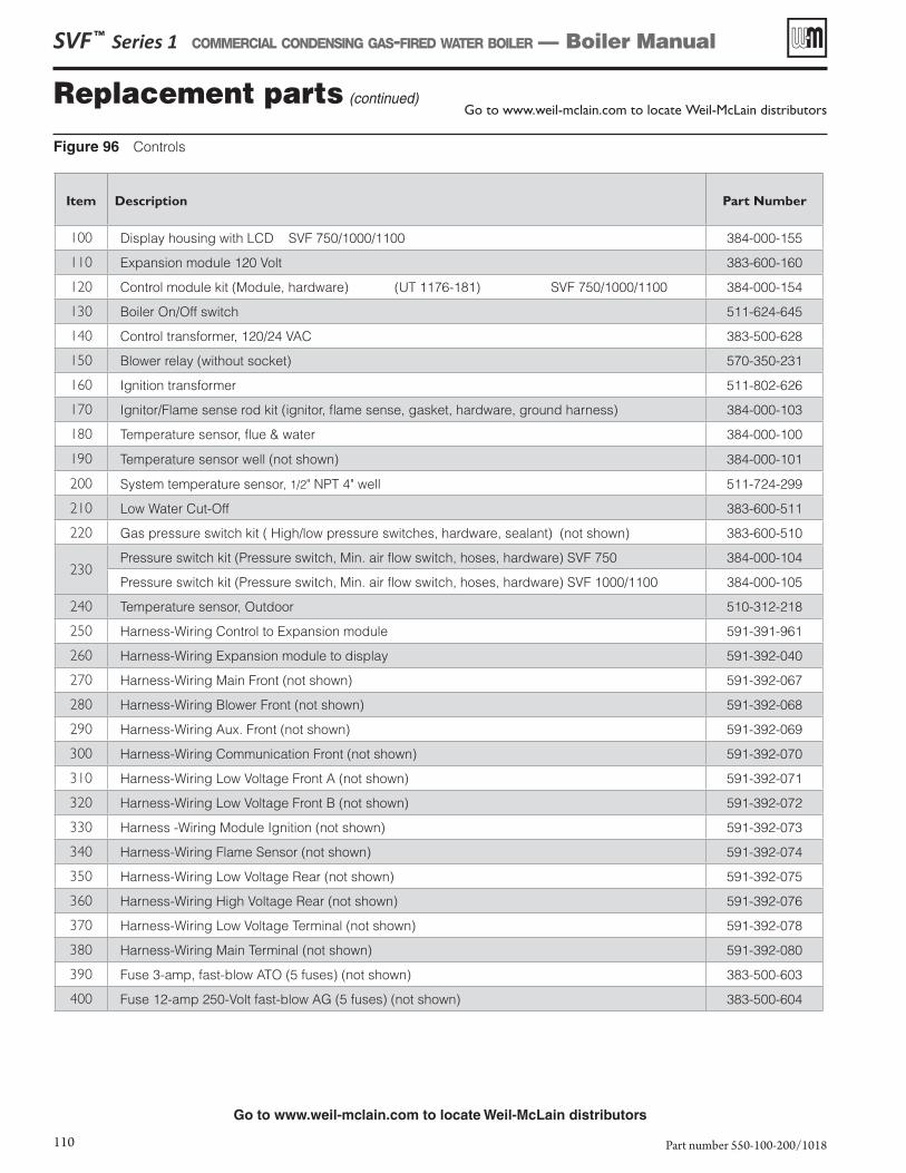
Figure 96 Controls
Replacement parts (continued)
Go to www.weil-mclain.com to locate Weil-McLain distributors
Go to www.weil-mclain.com to locate Weil-McLain distributors
SVF ™ Series 1 COMMERCIAL CONDENSING GAS-FIRED WATER BOILER — Boiler Manual
Part number 550-100-200/1018110
Item Description Part Number
100 Display housing with LCD SVF 750/1000/1100 384-000-155
110 Expansion module 120 Volt 383-600-160
120 Control module kit (Module, hardware) (UT 1176-181) SVF 750/1000/1100 384-000-154
130 Boiler On/Off switch 511-624-645
140 Control transformer, 120/24 VAC 383-500-628
150 Blower relay (without socket) 570-350-231
160 Ignition transformer 511-802-626
170 Ignitor/Flame sense rod kit (ignitor, flame sense, gasket, hardware, ground harness) 384-000-103
180 Temperature sensor, flue & water 384-000-100
190 Temperature sensor well (not shown) 384-000-101
200 System temperature sensor, 1/2" NPT 4" well 511-724-299
210 Low Water Cut-Off 383-600-511
220 Gas pressure switch kit ( High/low pressure switches, hardware, sealant) (not shown) 383-600-510
230Pressure switch kit (Pressure switch, Min. air flow switch, hoses, hardware) SVF 750 384-000-104
Pressure switch kit (Pressure switch, Min. air flow switch, hoses, hardware) SVF 1000/1100 384-000-105
240 Temperature sensor, Outdoor 510-312-218
250 Harness-Wiring Control to Expansion module 591-391-961
260 Harness-Wiring Expansion module to display 591-392-040
270 Harness-Wiring Main Front (not shown) 591-392-067
280 Harness-Wiring Blower Front (not shown) 591-392-068
290 Harness-Wiring Aux. Front (not shown) 591-392-069
300 Harness-Wiring Communication Front (not shown) 591-392-070
310 Harness-Wiring Low Voltage Front A (not shown) 591-392-071
320 Harness-Wiring Low Voltage Front B (not shown) 591-392-072
330 Harness -Wiring Module Ignition (not shown) 591-392-073
340 Harness-Wiring Flame Sensor (not shown) 591-392-074
350 Harness-Wiring Low Voltage Rear (not shown) 591-392-075
360 Harness-Wiring High Voltage Rear (not shown) 591-392-076
370 Harness-Wiring Low Voltage Terminal (not shown) 591-392-078
380 Harness-Wiring Main Terminal (not shown) 591-392-080
390 Fuse 3-amp, fast-blow ATO (5 fuses) (not shown) 383-500-603
400 Fuse 12-amp 250-Volt fast-blow AG (5 fuses) (not shown) 383-500-604
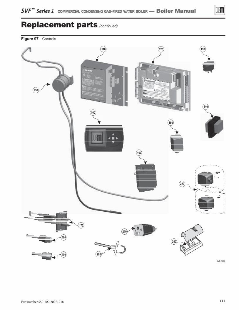
Figure 97 Controls
Replacement parts (continued)
SVF ™ Series 1 COMMERCIAL CONDENSING GAS-FIRED WATER BOILER — Boiler Manual
Part number 550-100-200/1018 111
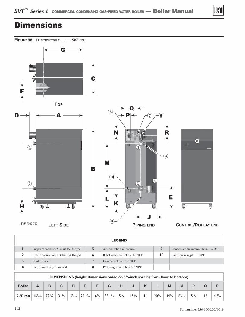
SVF ™ Series 1 COMMERCIAL CONDENSING GAS-FIRED WATER BOILER — Boiler Manual
Part number 550-100-200/1018112
Figure 98 Dimensional data — SVF 750
Dimensions
DIMENSIONS (height dimensions based on 5¼-inch spacing from floor to bottom)
����� A B C D E F G H J K L M N P Q R
SVF 750 469/16 79 ⅜ 31⅝ 65/16 2215/16 6⅞ 3811/16 5¼ 15¾ 11 20⅜ 44⅜ 67/16 51/4 12 615/16
LEGEND
1 Supply connection, 2” Class 150 flanged 5 Air connection, 6” nominal 9 Condensate drain connection, 1 ¼ O.D.
2 Return connection, 2” Class 150 flanged 6 Relief valve connection, ¾” NPT 10 Boiler drain nipple, 1” NPT
3 Control panel 7 Gas connection, 1 ¼” NPT
4 Flue connection, 6” nominal 8 P/T gauge connection, ¼” NPT
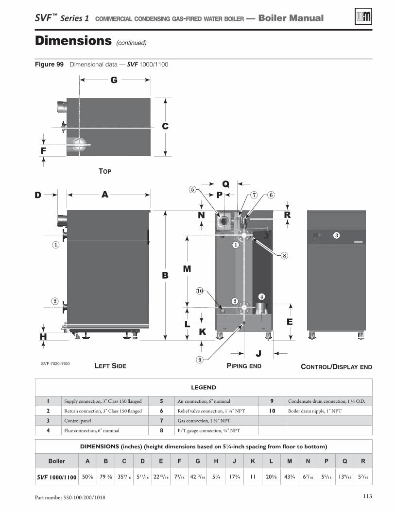
SVF ™ Series 1 COMMERCIAL CONDENSING GAS-FIRED WATER BOILER — Boiler Manual
Part number 550-100-200/1018 113
DIMENSIONS (inches) (height dimensions based on 5¼-inch spacing from floor to bottom)
����� A B C D E F G H J K L M N P Q R
SVF 1000/1100 50⅞ 79 ⅜ 359/16 511/16 2215/16 73/16 4213/16 5¼ 17¾ 11 20⅜ 43¾ 67/16 55/16 139/16 57/16
Figure 99 Dimensional data — SVF 1000/1100
Dimensions (continued)
LEGEND
1 Supply connection, 3” Class 150 flanged 5 Air connection, 6” nominal 9 Condensate drain connection, 1 ¼ O.D.
2 Return connection, 3” Class 150 flanged 6 Relief valve connection, 1 ¼” NPT 10 Boiler drain nipple, 1” NPT
3 Control panel 7 Gas connection, 1 ¼” NPT
4 Flue connection, 6” nominal 8 P/T gauge connection, ¼” NPT
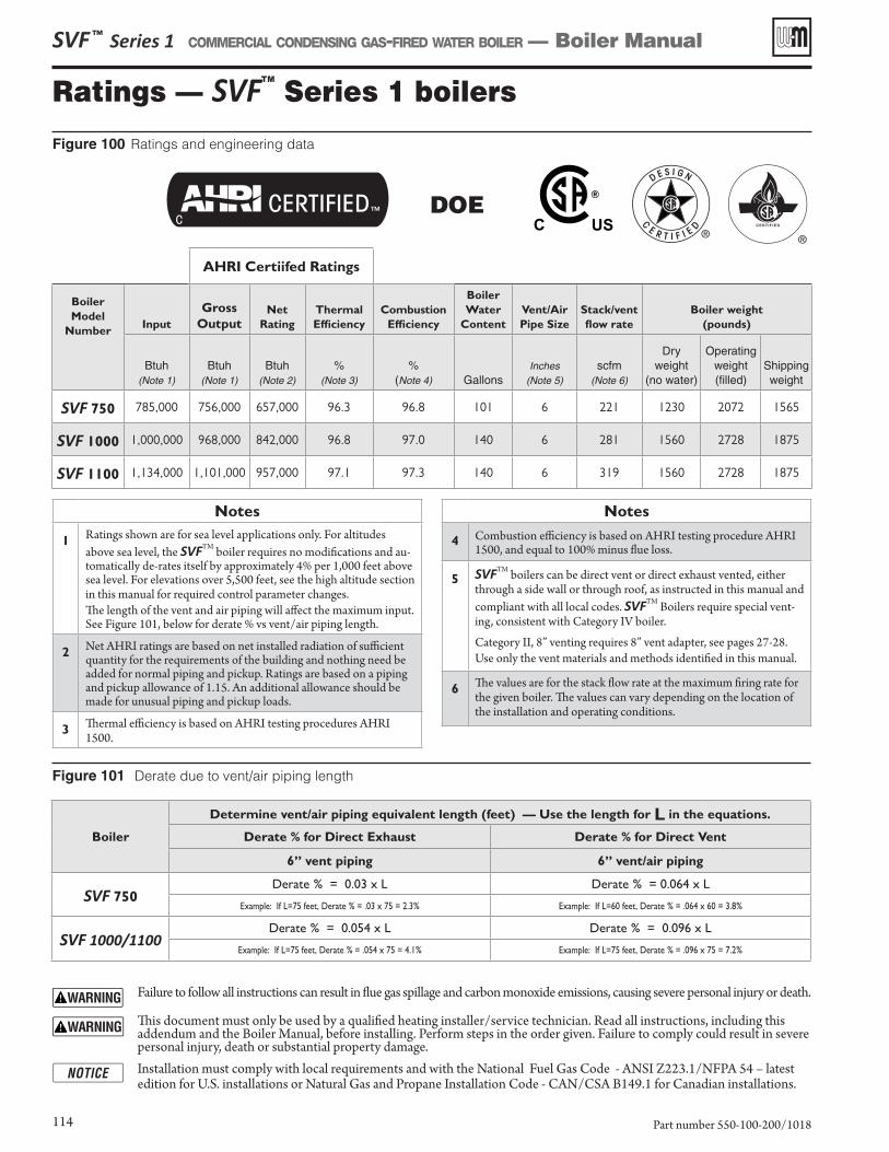
Ratings — SVFTM
Series 1 boilers
Figure 101 Derate due to vent/air piping length
SVF ™ Series 1 COMMERCIAL CONDENSING GAS-FIRED WATER BOILER — Boiler Manual
Part number 550-100-200/1018114
Failure to follow all instructions can result in flue gas spillage and carbon monoxide emissions, causing severe personal injury or death.
This document must only be used by a qualified heating installer/service technician. Read all instructions, including this addendum and the Boiler Manual, before installing. Perform steps in the order given. Failure to comply could result in severe personal injury, death or substantial property damage.
Installation must comply with local requirements and with the National Fuel Gas Code - ANSI Z223.1/NFPA 54 – latest edition for U.S. installations or Natural Gas and Propane Installation Code - CAN/CSA B149.1 for Canadian installations.
Boiler
Determine vent/air piping equivalent length (feet) — Use the length for L in the equations.
Derate % for Direct Exhaust Derate % for Direct Vent
6” vent piping 6” vent/air piping
SVF 750Derate % = 0.03 x L Derate % = 0.064 x L
Example: If L=75 feet, Derate % = .03 x 75 = 2.3% Example: If L=60 feet, Derate % = .064 x 60 = 3.8%
SVF 1000/1100Derate % = 0.054 x L Derate % = 0.096 x L
Example: If L=75 feet, Derate % = .054 x 75 = 4.1% Example: If L=75 feet, Derate % = .096 x 75 = 7.2%
Notes
1Ratings shown are for sea level applications only. For altitudes above sea level, the SVFTM boiler requires no modifications and au-tomatically de-rates itself by approximately 4% per 1,000 feet above sea level. For elevations over 5,500 feet, see the high altitude section in this manual for required control parameter changes.The length of the vent and air piping will affect the maximum input. See Figure 101, below for derate % vs vent/air piping length.
2Net AHRI ratings are based on net installed radiation of sufficient quantity for the requirements of the building and nothing need be added for normal piping and pickup. Ratings are based on a piping and pickup allowance of 1.15. An additional allowance should be made for unusual piping and pickup loads.
3Thermal efficiency is based on AHRI testing procedures AHRI 1500.
Notes
4 Combustion efficiency is based on AHRI testing procedure AHRI 1500, and equal to 100% minus flue loss.
5 SVFTM boilers can be direct vent or direct exhaust vented, either through a side wall or through roof, as instructed in this manual and compliant with all local codes. SVFTM Boilers require special vent-ing, consistent with Category IV boiler.
Category II, 8” venting requires 8” vent adapter, see pages 27-28. Use only the vent materials and methods identified in this manual.
6The values are for the stack flow rate at the maximum firing rate for the given boiler. The values can vary depending on the location of the installation and operating conditions.
AHRI Certiifed Ratings
Boiler
Model
NumberInput
Gross
OutputNet
Rating
Thermal
Efficiency
Combustion
Efficiency
Boiler
Water
Content
Vent/Air
Pipe Size
Stack/vent
flow rate
Boiler weight
(pounds)
Btuh(Note 1)
Btuh(Note 1)
Btuh(Note 2)
%(Note 3)
%(Note 4) Gallons
Inches(Note 5)
scfm(Note 6)
Dry weight
(no water)
Operating weight (filled)
Shippingweight
SVF 750 785,000 756,000 657,000 96.3 96.8 101 6 221 1230 2072 1565
SVF 1000 1,000,000 968,000 842,000 96.8 97.0 140 6 281 1560 2728 1875
SVF 1100 1,134,000 1,101,000 957,000 97.1 97.3 140 6 319 1560 2728 1875
Figure 100 Ratings and engineering data
DOE
SVF ™ Series 1 COMMERCIAL CONDENSING GAS-FIRED WATER BOILER — Boiler Manual
Part number 550-100-200/1018 115
Installation and Service Certificate
Boiler Model Series CP Number Date Installed BTU Input ❏ Installation instructions have been followed. ❏ Check-out sequence has been performed. ❏ Above information is certified to be correct. ❏ Information received and left with owner/maintenance person.
Installer
(Company) (Address) (Phone) (Installer's Signature)
SVF ™ Series 1 COMMERCIAL CONDENSING GAS-FIRED WATER BOILER — Boiler Manual
Part number 550-100-200/1018116
Installation and Gas Boiler Data Collection Sheet
���������������������SVF ________ / ����� _______ ��������������: ___________________
� �!"�#��: __________________ Fuel Type: ___________ BTU Input: ____________
�������������� �������������������������������������������� �������������� ��������������������������������������
Was venturi changed? YES___ NO___ Was gas valve throttle adjusted? YES___ NO___ Was gas valve offset adjusted? YES___ NO___
������������� !�����$�������� ����%�&��������
Boiler Model: SVF __________ Boiler Address: ____ System Type: ___________Control Type: _________ Net Max On Time: _____Min Target Mod Sensor: ___________High Altitude: YES___ NO___ Net Min On Time: _____Min Target Adjust: ___________
Max Rate On Net: _____% Supply Max: �������������Min Rate On Net: _____% Supply Min: �������������
��������������!�����"������������ Rotation & Sequence OD Reset Max: ���������������#$�"������������� Sequence Type: ______ OD Reset Min: �������������'�(������������������� Base Rate High: _____% Volts For Max: ___________ V���"������'(������ Base Rate Low: _____% Volts For Min: ___________ VCirculator 1: ON___ OFF___ Boiler Rotation Type: _________ Boost Time: ___________ MinsCirculator 2: ON___ OFF___ Rotate Frequency: ____Days System Off Diff: �������������Circulator 3: ON___ OFF___ Force Lead Rotation: YES or NO System On Diff: �������������Boiler Circ: ON___ OFF___ Modbus Settings Add BLR Diff: �����������������)�� �������� Enable: YES___ NO___ Drop BLR Diff: �������������Circulator 1: ON___ OFF___ Address: __________ Mod Delay Time: ___________ MinsCirculator 2: ON___ OFF___ Parity Bit: __________ Stabilization Time: ___________ MinsCirculator 3: ON___ OFF___ Baud Rate: _________bps Add Delay Time: ___________SecBoiler Circ: ON___ OFF___ Stop Bit: YES___ NO___ Drop Delay Time: ___________SecAssign Inputs Max BLR Temp: �������������Input 1: Priority___ Aux___ OFF___ Boiler On Diff: �������������
Source: TT1 ___ OR 0-10V ___ Boiler Off Diff: �������������Input 2: Priority___ Aux___ OFF___ Max On Time: ___________ MinsInput 3: Priority___ Aux___ OFF___ Run Boiler Pump: YES___ NO___
Run Aux Pump/Output: YES___ NO___Max Rate Volts: __________V Pre Pump: ___________SecMin Rate Volts: __________V Post Pump: ___________SecTemp Dependent: YES___ NO___ Max Rate: ___________%�$"�#�������������� Min Rate: ___________%
Activate Contact below setpoint: 1st____ 2nd____
Max System BTUs: __________ MBUTsMin Boilers On: ___________Additional Heat Demand: 1st___ 2nd___ OFF__Response Time: ___________ Mins
ODT YES___ NO___
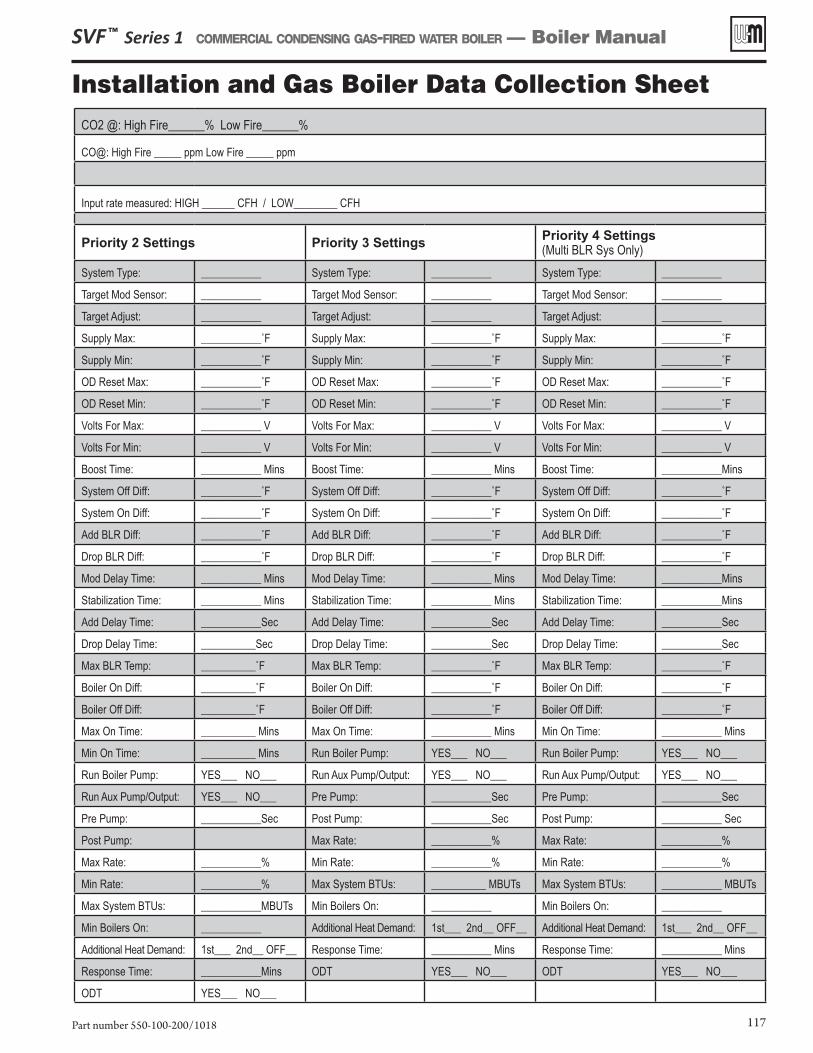
SVF ™ Series 1 COMMERCIAL CONDENSING GAS-FIRED WATER BOILER — Boiler Manual
Part number 550-100-200/1018 117
Installation and Gas Boiler Data Collection SheetCO2 @: High Fire______% Low Fire______%
CO@: High Fire _____ ppm Low Fire _____ ppm
Input rate measured: HIGH ______ CFH / LOW________ CFH
����%�*�������� ����%�+�������� ����%�,��������(Multi BLR Sys Only)
System Type: ___________ System Type: ___________ System Type: ___________
Target Mod Sensor: ___________ Target Mod Sensor: ___________ Target Mod Sensor: ___________
Target Adjust: ___________ Target Adjust: ___________ Target Adjust: ___________
Supply Max: ������������� Supply Max: ������������� Supply Max: �������������
Supply Min: ������������� Supply Min: ������������� Supply Min: �������������
OD Reset Max: ������������� OD Reset Max: ������������� OD Reset Max: �������������
OD Reset Min: ������������� OD Reset Min: ������������� OD Reset Min: �������������
Volts For Max: ___________ V Volts For Max: ___________ V Volts For Max: ___________ V
Volts For Min: ___________ V Volts For Min: ___________ V Volts For Min: ___________ V
Boost Time: ___________ Mins Boost Time: ___________ Mins Boost Time: ___________Mins
System Off Diff: ������������� System Off Diff: ������������� System Off Diff: �������������
System On Diff: ������������� System On Diff: ������������� System On Diff: �������������
Add BLR Diff: ������������� Add BLR Diff: ������������� Add BLR Diff: �������������
Drop BLR Diff: ������������� Drop BLR Diff: ������������� Drop BLR Diff: �������������
Mod Delay Time: ___________ Mins Mod Delay Time: ___________ Mins Mod Delay Time: ___________Mins
Stabilization Time: ___________ Mins Stabilization Time: ___________ Mins Stabilization Time: ___________Mins
Add Delay Time: ___________Sec Add Delay Time: ___________Sec Add Delay Time: ___________Sec
Drop Delay Time: __________Sec Drop Delay Time: ___________Sec Drop Delay Time: ___________Sec
Max BLR Temp: ������������ Max BLR Temp: ������������� Max BLR Temp: �������������
Boiler On Diff: ������������ Boiler On Diff: ������������� Boiler On Diff: �������������
Boiler Off Diff: ������������ Boiler Off Diff: ������������� Boiler Off Diff: �������������
Max On Time: __________ Mins Max On Time: ___________ Mins Min On Time: ___________ Mins
Min On Time: __________ Mins Run Boiler Pump: YES___ NO___ Run Boiler Pump: YES___ NO___
Run Boiler Pump: YES___ NO___ Run Aux Pump/Output: YES___ NO___ Run Aux Pump/Output: YES___ NO___
Run Aux Pump/Output: YES___ NO___ Pre Pump: ___________Sec Pre Pump: ___________Sec
Pre Pump: ___________Sec Post Pump: ___________Sec Post Pump: ___________ Sec
Post Pump: Max Rate: ___________% Max Rate: ___________%
Max Rate: ___________% Min Rate: ___________% Min Rate: ___________%
Min Rate: ___________% Max System BTUs: __________ MBUTs Max System BTUs: ___________ MBUTs
Max System BTUs: ___________MBUTs Min Boilers On: ___________ Min Boilers On: ___________
Min Boilers On: ___________ Additional Heat Demand: 1st___ 2nd__ OFF__ Additional Heat Demand: 1st___ 2nd__ OFF__
Additional Heat Demand: 1st___ 2nd__ OFF__ Response Time: ___________ Mins Response Time: ___________ Mins
Response Time: ___________Mins ODT YES___ NO___ ODT YES___ NO___
ODT YES___ NO___
SVF ™ Series 1 COMMERCIAL CONDENSING GAS-FIRED WATER BOILER — Boiler Manual
Part number 550-100-200/1018118
Notes
SVF ™ Series 1 COMMERCIAL CONDENSING GAS-FIRED WATER BOILER — Boiler Manual
Part number 550-100-200/1018 119
Notes (continued)
SVF ™ Series 1 COMMERCIAL CONDENSING GAS-FIRED WATER BOILER — Boiler Manual