Embed Size (px)
Citation preview

SurePOS 500 Series
Hardware Service Guide for Models 545
and 565
SY27-0423-01Update April 23, 2007
���

SurePOS 500 Series
Hardware Service Guide for Models 545
and 565
SY27-0423-01Update April 23, 2007
���

Note
Before using this information and the product it supports, be sure to read “Safety and environmental notices” on page xi and
the general information in Appendix D, “Notices,” on page 131.
Second Edition (May 2007)
This edition applies to the IBM® SurePOS Machine Type 4846, Models 545 and 565 and to all subsequent releases
and modifications until otherwise indicated in new editions.
Current versions of Retail Store Solutions documentation are available on the IBM Retail Store Solutions Web site at:
www.ibm.com/solutions/retail/store/support. Click Publications.
Order publications through your IBM representative or the IBM branch office serving your locality. Publications are
not stocked at the address given below.
A form for readers’ comments is also provided at the back of this publication. If this form has been removed, address
your comments to:
IBM Corporation
Retail Store Solutions Information Development
Department ZBDA
P.O. Box 12195
RESEARCH TRIANGLE PARK, NC 27709-9990
U.S.A.
When you send information to IBM, you grant IBM a nonexclusive right to use or distribute the information in any
way it believes appropriate without incurring any obligation to you.
© Copyright International Business Machines Corporation 2006, 2007. All rights reserved.
US Government Users Restricted Rights – Use, duplication or disclosure restricted by GSA ADP Schedule Contract
with IBM Corp.
Update April 23, 2007

Contents
Figures . . . . . . . . . . . . . . . . . . . . . . . . . . . vii
Tables . . . . . . . . . . . . . . . . . . . . . . . . . . . . ix
Safety and environmental notices . . . . . . . . . . . . . . . . . xi
Safety Information . . . . . . . . . . . . . . . . . . . . . . . . xi
Environmental notices and statements . . . . . . . . . . . . . . . . xvii
End of life disposal . . . . . . . . . . . . . . . . . . . . . . xvii
Battery disposal . . . . . . . . . . . . . . . . . . . . . . . xvii
Mercury-added statement . . . . . . . . . . . . . . . . . . . xviii
Magnetic stripe reader . . . . . . . . . . . . . . . . . . . . . xviii
Handling static-sensitive devices . . . . . . . . . . . . . . . . . xviii
About this guide . . . . . . . . . . . . . . . . . . . . . . . xix
Who should read this guide . . . . . . . . . . . . . . . . . . . . xix
Related publications . . . . . . . . . . . . . . . . . . . . . . . xix
Publications accessibility . . . . . . . . . . . . . . . . . . . . . xix
Web sites . . . . . . . . . . . . . . . . . . . . . . . . . . . xix
Providing feedback . . . . . . . . . . . . . . . . . . . . . . . xix
Summary of changes . . . . . . . . . . . . . . . . . . . . . . xxi
May, 2007 . . . . . . . . . . . . . . . . . . . . . . . . . . xxi
Chapter 1. Introducing the IBM SurePOS 500 Series Models 545 and 565 1
Models and features . . . . . . . . . . . . . . . . . . . . . . . 2
Optional features . . . . . . . . . . . . . . . . . . . . . . . 4
Connectors, power, and brightness controls . . . . . . . . . . . . . . . 5
Supported operating systems . . . . . . . . . . . . . . . . . . . . 7
Understanding the display and operating system restrictions . . . . . . . 7
Supported devices . . . . . . . . . . . . . . . . . . . . . . . . 9
System management . . . . . . . . . . . . . . . . . . . . . . . 9
System management programs . . . . . . . . . . . . . . . . . . 9
Remote management . . . . . . . . . . . . . . . . . . . . . 10
Compatible products . . . . . . . . . . . . . . . . . . . . . . . 11
Locating the machine serial number . . . . . . . . . . . . . . . . . 11
Chapter 2. Running diagnostics and troubleshooting . . . . . . . . . 13
Using the CMOS Setup Utility . . . . . . . . . . . . . . . . . . . 13
Using the Main window . . . . . . . . . . . . . . . . . . . . . 13
Restoring the default CMOS settings . . . . . . . . . . . . . . . . 15
Clearing the CMOS settings . . . . . . . . . . . . . . . . . . . 15
Real-time clock and CMOS . . . . . . . . . . . . . . . . . . . 16
Configuring the COM (communication) ports . . . . . . . . . . . . . 16
Using the IBM Diagnostics for POS Systems and Peripherals package . . . . 16
Supported memory keys . . . . . . . . . . . . . . . . . . . . 17
Updating the flash BIOS . . . . . . . . . . . . . . . . . . . . . 17
Power interruption during flash BIOS update procedure . . . . . . . . . 18
Repairing the flash BIOS . . . . . . . . . . . . . . . . . . . . 18
Diagnosing problems and troubleshooting . . . . . . . . . . . . . . . 19
Researching the Knowledgebase . . . . . . . . . . . . . . . . . 19
Preliminary checklist . . . . . . . . . . . . . . . . . . . . . . 19
Troubleshooting symptoms and actions . . . . . . . . . . . . . . . 20
CMOS recovery . . . . . . . . . . . . . . . . . . . . . . . . 23
Update April 23, 2007
© Copyright IBM Corp. 2006, 2007 iii

Chapter 3. Removing and replacing FRUs for the SurePOS 500 Models 545
and 565 . . . . . . . . . . . . . . . . . . . . . . . . . . 25
Opening and removing covers and assemblies . . . . . . . . . . . . . 26
Handling static-sensitive devices . . . . . . . . . . . . . . . . . . 28
Modular service tools . . . . . . . . . . . . . . . . . . . . . 29
Removing the covers . . . . . . . . . . . . . . . . . . . . . . 30
Front (or HDD) cover removal . . . . . . . . . . . . . . . . . . 30
Rear cover removal . . . . . . . . . . . . . . . . . . . . . . 31
Opening the I/O tailgate cover . . . . . . . . . . . . . . . . . . 32
Top cover removal . . . . . . . . . . . . . . . . . . . . . . 33
Hinge cover removal . . . . . . . . . . . . . . . . . . . . . . 34
Display tablet - removing and replacing . . . . . . . . . . . . . . . . 35
Display tablet cable – removing and replacing . . . . . . . . . . . . 36
Front bezel and LCD assembly - removing and replacing . . . . . . . . . 37
Operator card - removing and replacing . . . . . . . . . . . . . . . 39
Tablet hinge assembly – removing and replacing . . . . . . . . . . . . 40
Hard disk drive and bracket – removing and replacing . . . . . . . . . . 41
Hard disk drive fan and bracket – removing and replacing . . . . . . . . . 43
Hard disk drive cables – removing and replacing . . . . . . . . . . . . 44
Cable tie bar – removing and replacing . . . . . . . . . . . . . . . . 45
Power supply – removing and replacing . . . . . . . . . . . . . . . . 46
Power supply latch arm – removing and replacing . . . . . . . . . . . . 47
Rear connector panel (tailgate) – removing and replacing . . . . . . . . . 48
System board – removing and replacing . . . . . . . . . . . . . . . 50
System-board jumper location and settings . . . . . . . . . . . . . 52
System-board battery – removing and replacing . . . . . . . . . . . . 52
Processor fan/heatsink assembly - removing and replacing . . . . . . . 54
Processor module – removing and replacing . . . . . . . . . . . . . 55
Memory modules – removing and replacing . . . . . . . . . . . . . . 56
Memory modules and industry standards . . . . . . . . . . . . . . 57
Base plate – removing and replacing . . . . . . . . . . . . . . . . . 58
Optional features . . . . . . . . . . . . . . . . . . . . . . . . 59
Magnetic stripe reader (MSR) – removing and replacing . . . . . . . . . 59
MSR hole plug – removing and replacing . . . . . . . . . . . . . . 60
PC card blank – removing . . . . . . . . . . . . . . . . . . . . 60
PC card – removing and replacing . . . . . . . . . . . . . . . . . 61
Video adapter card– removing and replacing . . . . . . . . . . . . . 63
Speaker – removing and replacing . . . . . . . . . . . . . . . . . 64
Integrated customer display – removing and replacing . . . . . . . . . 66
Modular flash drive – removing and replacing . . . . . . . . . . . . 67
Chapter 4. Mounting the SurePOS 500 Models 545 and 565 . . . . . . . 69
Mounting the base plate on a countertop . . . . . . . . . . . . . . . 71
Non-keyboard-integration tray mounting . . . . . . . . . . . . . . . . 74
Countertop with non-keyboard-integration tray mounting . . . . . . . . . 74
Cash drawer . . . . . . . . . . . . . . . . . . . . . . . . . 79
Keyboard-integration tray . . . . . . . . . . . . . . . . . . . . . 84
Countertop and full-size cash drawer . . . . . . . . . . . . . . . . 84
Installing additional peripheral devices . . . . . . . . . . . . . . . . 93
Mounting a distributed customer display and APA display to a cash drawer 93
Installing IBM 4610 SureMark Models TF6 or TF7 printers . . . . . . . . 95
Appendix A. Field replaceable units . . . . . . . . . . . . . . . . 99
How to use the FRU catalog . . . . . . . . . . . . . . . . . . . . 99
Assembly 1: Models 545 and 565 . . . . . . . . . . . . . . . . . 100
Update April 23, 2007
iv Models 545 and 565 Hardware Service Guide
||
||
||
||

Assembly 2: Countertop and cash drawer keyboard integration tray and filler
panels . . . . . . . . . . . . . . . . . . . . . . . . . . . 104
Assembly 3: Optional peripherals . . . . . . . . . . . . . . . . . . 106
Assembly 4: Countertop non-keyboard integration tray and filler panels . . . . 108
Assembly 5: Cash drawer non-keyboard integration tray and filler panels . . . 110
Appendix B. Power cords . . . . . . . . . . . . . . . . . . . . 113
Appendix C. System specifications and planning information . . . . . . 115
Physical specifications and dimensions . . . . . . . . . . . . . . . 115
Dimensions with trays . . . . . . . . . . . . . . . . . . . . . 116
Dimensions of unit with 12-inch display . . . . . . . . . . . . . . 118
Dimensions of unit with 15-inch display . . . . . . . . . . . . . . 119
Dimensions of unit with 17-inch display . . . . . . . . . . . . . . 120
Power requirements and consumption . . . . . . . . . . . . . . . . 121
Power . . . . . . . . . . . . . . . . . . . . . . . . . . . 121
Port power ratings . . . . . . . . . . . . . . . . . . . . . . 121
Connector-pin assignments . . . . . . . . . . . . . . . . . . . . 122
External connectors . . . . . . . . . . . . . . . . . . . . . . 122
Temperature, humidity, and altitude limits . . . . . . . . . . . . . . . 130
Appendix D. Notices . . . . . . . . . . . . . . . . . . . . . . 131
Electronic emission notices . . . . . . . . . . . . . . . . . . . . 133
Federal Communications Commission (FCC) Statement . . . . . . . . 133
Industry Canada Class A Emission Compliance Statement . . . . . . . 133
Avis de conformité aux normes d’Industrie Canada . . . . . . . . . . 133
European Union (EU) Mark of Conformity Statement . . . . . . . . . 133
Germany . . . . . . . . . . . . . . . . . . . . . . . . . 133
Australia / New Zealand . . . . . . . . . . . . . . . . . . . . 134
Japanese power line harmonics compliance statement . . . . . . . . . . 134
Japanese Voluntary Control Council for Interference (VCCI) Statement . . . . 134
Korean Communications Statement . . . . . . . . . . . . . . . . . 135
Chinese Class A warning statement . . . . . . . . . . . . . . . . . 135
Taiwanese Class A warning statement . . . . . . . . . . . . . . . . 135
Taiwan contact information . . . . . . . . . . . . . . . . . . . 136
Taiwan recycle statement . . . . . . . . . . . . . . . . . . . 136
Electrostatic Discharge (ESD) . . . . . . . . . . . . . . . . . . . 136
Trademarks . . . . . . . . . . . . . . . . . . . . . . . . . . 137
Appendix E. Safety information . . . . . . . . . . . . . . . . . 139
Safety Information-English . . . . . . . . . . . . . . . . . . . . 139
Safety Information-Arabic . . . . . . . . . . . . . . . . . . . . 141
Safety Information-Brazilian Portuguese . . . . . . . . . . . . . . . 143
Safety Information-French . . . . . . . . . . . . . . . . . . . . 145
Safety Information-Hebrew . . . . . . . . . . . . . . . . . . . . 148
Safety Information-Korean . . . . . . . . . . . . . . . . . . . . 150
Safety Information-Italian . . . . . . . . . . . . . . . . . . . . . 153
Safety Information-Spanish . . . . . . . . . . . . . . . . . . . . 156
Safety Information-German . . . . . . . . . . . . . . . . . . . . 158
Safety Information-Traditional Chinese . . . . . . . . . . . . . . . . 160
Glossary . . . . . . . . . . . . . . . . . . . . . . . . . . 163
Part number index . . . . . . . . . . . . . . . . . . . . . . . 171
Index . . . . . . . . . . . . . . . . . . . . . . . . . . . . 173
Update April 23, 2007
Contents v
||

Update April 23, 2007
vi Models 545 and 565 Hardware Service Guide

Figures
1. IBM SurePOS 500 Series configuration with optional features . . . . . . . . . . . . . . . 1
2. Tablet connectors . . . . . . . . . . . . . . . . . . . . . . . . . . . . . . . 5
3. Rear view of input/output available on all models . . . . . . . . . . . . . . . . . . . 6
4. Serial number location . . . . . . . . . . . . . . . . . . . . . . . . . . . . . 11
5. CMOS Setup Utility main window . . . . . . . . . . . . . . . . . . . . . . . . . 14
6. CMOS reset jumper J25 . . . . . . . . . . . . . . . . . . . . . . . . . . . . 15
7. Unlatching the front cover . . . . . . . . . . . . . . . . . . . . . . . . . . . 30
8. Removing the rear cover . . . . . . . . . . . . . . . . . . . . . . . . . . . . 31
9. Opening the I/O tailgate cover . . . . . . . . . . . . . . . . . . . . . . . . . . 32
10. Locating the top cover release latch . . . . . . . . . . . . . . . . . . . . . . . . 33
11. Removing the hinge cover . . . . . . . . . . . . . . . . . . . . . . . . . . . 34
12. Removing the display tablet . . . . . . . . . . . . . . . . . . . . . . . . . . . 35
13. Removing the display tablet cable from the system board . . . . . . . . . . . . . . . . 36
14. Disconnecting the touch cable and removing the front bezel . . . . . . . . . . . . . . . 37
15. View of L-shaped keyways . . . . . . . . . . . . . . . . . . . . . . . . . . . 38
16. Removing the operator card . . . . . . . . . . . . . . . . . . . . . . . . . . . 39
17. Removing the tablet hinge assembly . . . . . . . . . . . . . . . . . . . . . . . 40
18. HDD installation . . . . . . . . . . . . . . . . . . . . . . . . . . . . . . . 41
19. Removing the hard disk drive and bracket . . . . . . . . . . . . . . . . . . . . . 42
20. Removing the HDD fan and bracket . . . . . . . . . . . . . . . . . . . . . . . . 43
21. Removing the cable tie bar . . . . . . . . . . . . . . . . . . . . . . . . . . . 45
22. Removing the power supply . . . . . . . . . . . . . . . . . . . . . . . . . . . 46
23. Removing the power supply latch arm . . . . . . . . . . . . . . . . . . . . . . . 47
24. Opening the I/O tailgate cover . . . . . . . . . . . . . . . . . . . . . . . . . . 48
25. Removing the tailgate . . . . . . . . . . . . . . . . . . . . . . . . . . . . . 49
26. Removing the system board . . . . . . . . . . . . . . . . . . . . . . . . . . . 50
27. System board jumper location . . . . . . . . . . . . . . . . . . . . . . . . . . 52
28. System-board battery . . . . . . . . . . . . . . . . . . . . . . . . . . . . . 53
29. Removing the processor fan/ heatsink assembly . . . . . . . . . . . . . . . . . . . 54
30. Memory socket location . . . . . . . . . . . . . . . . . . . . . . . . . . . . 56
31. Memory module removal . . . . . . . . . . . . . . . . . . . . . . . . . . . . 57
32. Removing the base plate . . . . . . . . . . . . . . . . . . . . . . . . . . . . 58
33. Removing the MSR . . . . . . . . . . . . . . . . . . . . . . . . . . . . . . 59
34. Removing the PC card adapter slot blank . . . . . . . . . . . . . . . . . . . . . . 61
35. Removing a PC card adapter . . . . . . . . . . . . . . . . . . . . . . . . . . 62
36. Video adapter card removal . . . . . . . . . . . . . . . . . . . . . . . . . . . 63
37. Removing the speaker thumbscrew . . . . . . . . . . . . . . . . . . . . . . . . 64
38. Removing the speaker and speaker EMC shield . . . . . . . . . . . . . . . . . . . 65
39. Removing the integrated display . . . . . . . . . . . . . . . . . . . . . . . . . 66
40. Modular flash drive . . . . . . . . . . . . . . . . . . . . . . . . . . . . . . 67
41. Base plate countertop dimensions . . . . . . . . . . . . . . . . . . . . . . . . 72
42. Attaching the base foot to the countertop . . . . . . . . . . . . . . . . . . . . . . 73
43. Countertop with non-keyboard-integration tray mounting . . . . . . . . . . . . . . . . 74
44. Countertop integration tray pattern with display and countertop cutout on right side . . . . . . 75
45. Detaching the fence from the tray . . . . . . . . . . . . . . . . . . . . . . . . . 75
46. Sliding the fence off of the integration tray . . . . . . . . . . . . . . . . . . . . . 76
47. Overview of integration tray, SurePOS 500, printer, and filler panels . . . . . . . . . . . . 77
48. Connecting filler panels . . . . . . . . . . . . . . . . . . . . . . . . . . . . 78
49. Attaching the integration tray to cash drawer . . . . . . . . . . . . . . . . . . . . 79
50. Attaching a mounting plate to center of cash-drawer integration tray . . . . . . . . . . . . 80
51. Attaching mounting plate to the cash drawer integration tray . . . . . . . . . . . . . . . 81
52. Attaching filler panels and the rear modesty cover . . . . . . . . . . . . . . . . . . 83
53. Full-size keyboard-integration tray on a countertop . . . . . . . . . . . . . . . . . . 84
Update April 23, 2007
© Copyright IBM Corp. 2006, 2007 vii
||
||
||

54. Countertop keyboard-integration tray assembly . . . . . . . . . . . . . . . . . . . . 86
55. Installing the keyboard-integration tray on a cash drawer . . . . . . . . . . . . . . . . 87
56. Installing the SurePOS 500 onto the integration tray . . . . . . . . . . . . . . . . . . 88
57. Installing the 4610 printer onto the integration tray . . . . . . . . . . . . . . . . . . 89
58. Installing the keyboard onto the integration tray . . . . . . . . . . . . . . . . . . . 90
59. Attaching the distributed customer display cable . . . . . . . . . . . . . . . . . . . 90
60. Installing the distributed customer display onto the integration tray . . . . . . . . . . . . 91
61. Attaching the distributed customer display cable . . . . . . . . . . . . . . . . . . . 93
62. Attaching the distributed customer display to the system unit . . . . . . . . . . . . . . . 94
63. Installing the distributed customer display onto the keyboard integration tray . . . . . . . . . 95
64. 4610 TF6 or TF7 printer connector locations . . . . . . . . . . . . . . . . . . . . . 96
65. Attaching and routing the cables to the printer. . . . . . . . . . . . . . . . . . . . . 97
66. Attaching the 4610 TF6 or TF7 printer mounting plate for a non-keyboard integration tray . . . . 97
67. 4610 TF6 or TF7 cable routing . . . . . . . . . . . . . . . . . . . . . . . . . . 98
68. Dimensions of SurePOS Models 545 and 565 with retail tray . . . . . . . . . . . . . . 116
69. Dimensions of SurePOS Models 545 and 565 with counter top tray . . . . . . . . . . . . 117
70. SurePOS Models 545 and 565 with cash drawer tray . . . . . . . . . . . . . . . . . 117
71. Dimensions of unit with 12-inch display . . . . . . . . . . . . . . . . . . . . . . 118
72. Dimensions of unit with 15-inch display . . . . . . . . . . . . . . . . . . . . . . 119
Update April 23, 2007
viii Models 545 and 565 Hardware Service Guide

Tables
1. 4846 Models 545 and 565 summary . . . . . . . . . . . . . . . . . . . . . . . . 2
2. E and P Models . . . . . . . . . . . . . . . . . . . . . . . . . . . . . . . . 3
3. Status indicators . . . . . . . . . . . . . . . . . . . . . . . . . . . . . . . 3
4. Controls and connectors . . . . . . . . . . . . . . . . . . . . . . . . . . . . 5
5. Rear connectors . . . . . . . . . . . . . . . . . . . . . . . . . . . . . . . 6
6. SurePOS 500 Models 545 and 565 supported operating systems . . . . . . . . . . . . . 7
7. Operating system with display combinations and restrictions . . . . . . . . . . . . . . . 8
8. Supported video resolutions in Windows operating system . . . . . . . . . . . . . . . . 8
9. Summary of tested and supported devices . . . . . . . . . . . . . . . . . . . . . . 9
10. SurePOS 500 task information . . . . . . . . . . . . . . . . . . . . . . . . . . 19
11. Symptoms and actions . . . . . . . . . . . . . . . . . . . . . . . . . . . . . 20
12. Pictorial overview of common removal tasks . . . . . . . . . . . . . . . . . . . . . 26
13. Service personnel tools . . . . . . . . . . . . . . . . . . . . . . . . . . . . 29
14. System board jumper settings . . . . . . . . . . . . . . . . . . . . . . . . . . 52
15. Mounting configurations . . . . . . . . . . . . . . . . . . . . . . . . . . . . 69
16. Countertop integration tray legend . . . . . . . . . . . . . . . . . . . . . . . . 77
17. Countertop integration tray legend . . . . . . . . . . . . . . . . . . . . . . . . 86
18. 4610 SureMark printer on a full-size keyboard-integration tray legend . . . . . . . . . . . 89
19. Power cord lengths and part numbers by country . . . . . . . . . . . . . . . . . . 113
20. Height, weight and depth of the SurePOS 500 Models 545 and 565 . . . . . . . . . . . 115
21. Weights of integrated, distributed displays and MSR . . . . . . . . . . . . . . . . . 115
22. SurePOS 500 Models 545 and 565 dimensions . . . . . . . . . . . . . . . . . . . 116
23. Input voltage, frequency . . . . . . . . . . . . . . . . . . . . . . . . . . . . 121
24. SurePOS 500 Series Models 545 and 565 power supply . . . . . . . . . . . . . . . . 121
25. Power consumption . . . . . . . . . . . . . . . . . . . . . . . . . . . . . 121
26. Port current ratings . . . . . . . . . . . . . . . . . . . . . . . . . . . . . 122
27. Speaker connector-pin assignments . . . . . . . . . . . . . . . . . . . . . . . 122
28. MSR connector-pin assignments . . . . . . . . . . . . . . . . . . . . . . . . 122
29. USB port connector-pin assignments . . . . . . . . . . . . . . . . . . . . . . . 124
30. USB port connector-pin assignments . . . . . . . . . . . . . . . . . . . . . . . 124
31. Keyboard and mouse connector-pin assignments . . . . . . . . . . . . . . . . . . 124
32. Keyboard and mouse connector-pin assignments . . . . . . . . . . . . . . . . . . 125
33. Microphone connector-pin assignments . . . . . . . . . . . . . . . . . . . . . . 125
34. Headphone connector-pin assignments . . . . . . . . . . . . . . . . . . . . . . 125
35. RJ-45 connector-pin assignments . . . . . . . . . . . . . . . . . . . . . . . . 126
36. Assignments for 15-pin serial connector . . . . . . . . . . . . . . . . . . . . . . 127
37. Ethernet connector-pin assignments . . . . . . . . . . . . . . . . . . . . . . . 127
38. Assignment of external-video connector pins . . . . . . . . . . . . . . . . . . . . 128
39. Assignment of cash drawer connector pins . . . . . . . . . . . . . . . . . . . . . 129
40. Assignment of integrated customer-display connector pins . . . . . . . . . . . . . . . 129
41. Temperature, humidity, altitude limits . . . . . . . . . . . . . . . . . . . . . . . 130
Update April 23, 2007
© Copyright IBM Corp. 2006, 2007 ix

Update April 23, 2007
x Models 545 and 565 Hardware Service Guide

Safety and environmental notices
Safety notices are printed throughout this book.
A danger notice indicates the presence of a hazard that has the potential of causing
death or serious personal injury.
A caution notice indicates the presence of a hazard that has the potential of causing
moderate or minor personal injury.
An attention notice indicates the possibility of damage to a program, device,
system, or data.
A note provides important tips, guidance, or advice.
Safety Information
Danger:
Before you begin to install this product, read the safety information in IBM
Safety Information - Read This First, GA27–4004. This booklet describes safe
procedures for cabling and plugging in electrical equipment.
Gevaar:
Voordat u begint met de installatie van dit produkt, moet u eerst de
veiligheidsinstructies lezen in de brochure Veiligheidsinstructies—Lees dit
eerst, GA27–4004. Hierin wordt beschreven hoe u electrische apparatuur op
een veilige manier moet bekabelen en aansluiten.
Perigo:
Antes de começar a instalar este produto, leia as informações de segurança
contidas em Informações Sobre Seguranaça—Leia Isto Primeiro, GA27–4004.
Esse folheto descreve procedimentos de segurança para a instalação de
cabos e conexões em equipamentos elétricos.
Update April 23, 2007
© Copyright IBM Corp. 2006, 2007 xi

Fare!
Før du installerer dette produkt, skal du læse sikkerhedsforskrifterne i
Sikkerhedsforskrifter—Lœs dette først GA27–4004. Vejledningen beskriver den
fremgangsmåde, du skal bruge ved tilslutning af kabler og udstyr.
Gevaar
Voordat u begint met het installeren van dit produkt, dient u eerst de
veiligheidsrichtlijnen te lezen die zijn vermeld in de publikatie IBM Safety
Information — Read This First, GA27–4004. In dit boekje vindt u veilige
procedures voor het aansluiten van elektrische appratuur.
VAARA
Ennen kuin aloitat tämän tuotteen asennuksen, lue julkaisussa
Turvaohjeet—Luetämä ensin, GA27–4004, olevat turvaohjeet. Tässä
kirjasessa on ohjeet siitä, miten sähkölaitteet kaapeloidaan ja kytketään
turvallisesti.
Danger
Avant d’installer le présent produit, consultez le livret Informations pour la
sécurité–Lisez-moi d’abord, GA27–4004, qui décrit les procédures à respecter
pour effectuer les opérations de câblage et brancher les équipements
électriques en toute sécurité.
Update April 23, 2007
xii Models 545 and 565 Hardware Service Guide

Vorsicht
Bevor mit der Installation des Produktes begonnen wird, die
Sicherheitshinweise in Sicherheitsinformationen—Bitte zuerst lesen, IBM Form
GA27–4004. Diese Veröffentlichung beschreibt die Sicherheitsvorkehrungen
für das Verkabeln und Anschlieβen elektrischer Geräte.
Vigyázat
Mielôtt megkezdi a berendezés üzembe helyezését, olvassa el a IBM Safety
Information — Read This First, GA27–4004 könyvecskében leírt biztonsági
információkat. Ez a könyv leírja, milyen biztonsági intézkedéseket kell
megtenni az elektromos berendezés huzalozásakor illetve csatlakoztatásakor.
Pericolo
prima di iniziare l’installazione di questo prodotto, leggere le informazioni
relative alla sicurezza riportate nell’opuscolo Informazioni di sicurezza—Prime
informazioni da leggere in cui sono descritte le procedure per il cablaggio ed il
collegamento di apparecchiature elettriche.
Fare
Før du begynner å installere dette produktet, må du lese
sikkerhetsinformasjonen i Sikkerhetsinformasjon—Les dette først, GA27–4004
som beskriver sikkerhetsrutinene for kabling og tilkobling av elektrisk utstyr.
Update April 23, 2007
Safety and environmental notices xiii

Perigo
Antes de iniciar a instalação deste produto, leia as informações de segurança
Informações de Segurança—Leia Primeiro, GA27–4004. Este documento
descreve como efectuar, de um modo seguro, as ligações eléctricas dos
equipamentos.
Peligro
Antes de empezar a instalar este producto, lea la información de seguridad en
Información de Seguridad—Lea Esto Primero, GA27–4004. Este documento
describe los procedimientos de sequridad para cablear y enchufar equipos
eléctricos.
Varning—livsfara
Innan du börjar installera den här produkten bör du läsa
säkerhetsinformationen i dikumentet Säkerhetsföreskrifter—Läs detta först,
GA27–4004. Där beskrivs hur du på ett säkert sätt ansluter elektrisk
utrustning.
Update April 23, 2007
xiv Models 545 and 565 Hardware Service Guide

IBM
IBM
GA27-4004
GA27-4004
Update April 23, 2007
Safety and environmental notices xv

GA27-4004
GA27-4004
GA27-4004
GA27-4004
GA27-4004
GA27-4004
IBM
Update April 23, 2007
xvi Models 545 and 565 Hardware Service Guide

Environmental notices and statements
This section covers product recycling and product disposal.
End of life disposal
This unit must be recycled or discarded according to applicable local and national
regulations. IBM encourages owners of information technology (IT) equipment to
responsibly recycle their equipment when it is no longer needed. IBM offers a
variety of product return programs and services in several countries to assist
equipment owners in recycling their IT products. Information on IBM product
recycling offerings can be found on IBM’s Internet site at http://www.ibm.com/ibm/environment/products/prp.shtml.
Notice: This mark applies only to countries within the European Union (EU) and
Norway.
Appliances are labeled in accordance with European Directive 2002/96/EC
concerning waste electrical and electronic equipment (WEEE). The Directive
determines the framework for the return and recycling of used appliances as
applicable throughout the European Union. This label is applied to various products
to indicate that the product is not to be thrown away, but rather reclaimed upon end
of life per this Directive.
In accordance with the European WEEE Directive, electrical and electronic
equipment (EEE) is to be collected separately and to be reused, recycled, or
recovered at end of life. Users of EEE with the WEEE marking per Annex IV of the
WEEE Directive, as shown above, must not dispose of end of life EEE as unsorted
municipal waste, but use the collection framework available to customers for the
return, recycling, and recovery of WEEE. Customer participation is important to
minimize any potential effects of EEE on the environment and human health due to
the potential presence of hazardous substances in EEE. For proper collection and
treatment, contact your local IBM representative.
Disposal of IT products should be in accordance with local ordinances and
regulations.
Battery disposal
This unit contains batteries. Remove and discard these batteries, or recycle them,
according to local regulations. Return IBM units as determined by service
procedures.
Taiwanese battery recycling statement
Waste batteries, please recycle.
Update April 23, 2007
Safety and environmental notices xvii

Mercury-added statement
The fluorescent lamp in the liquid crystal display contains mercury. Dispose of it as
required by local ordinances and regulations.
Magnetic stripe reader
The electronic article surveillance (EAS) device that deactivates security tags
should not be closer than 18 in. (46 cm.) to the nearest edge of the magnetic stripe
reader (MSR).
Handling static-sensitive devices
Attention: Static electricity can damage electronic devices and your system. To
avoid damage, keep static-sensitive devices in their static protective bags until you
are ready to install them.
To reduce the possibility of electrostatic discharge, observe the following
precautions:
v Limit your movement. Movement can cause static electricity to build up around
you.
v Handle the device carefully, holding it by its edges or its frame.
v Do not touch solder joints, pins, or exposed printed circuitry.
v Do not leave the device where others can handle and possibly damage the
device.
v While the device is still in its anti-static bag, touch it to an unpainted metal part of
the system unit for at least 2 seconds. (This action removes static electricity from
the package and from your body.)
v Remove the device from its package and install it directly into your system,
without putting it down. If it is necessary to put the device down, place it onto its
static-protective bag. (If your device is an adapter, place it component side up.)
Do not place the device onto the cover of the system or onto a metal table.
v Take additional care when handling devices during cold weather because heating
reduces indoor humidity and increases static electricity.
Update April 23, 2007
xviii Models 545 and 565 Hardware Service Guide
|||

About this guide
This guide provides information necessary to repair and maintain the IBM
SurePOS® 500 Series Machine Type 4846, Models 545 and 565.
Who should read this guide
This guide is for the IBM service representative to assist in maintaining and
repairing the IBM SurePOS 500 Series Models 545 and 565.
Related publications
The SurePOS 500 Series library consists of the following publications:
v IBM SurePOS 500 Series Planning, Installation, and Operation Guide for Models
545 and 565, GA27-4330
This guide provides installation and setup information, including option installation
procedures and problem determination information.
v IBM SurePOS 500 Series Operating System Installation Guide for Models 545
and 565, GA30-4132
This guide provides step-by-step information on installing the operating software
for the product.
v IBM Point of Sale Options and I/O Devices Service Guide, GC30-9737
This guide describes the problem-determination and repair procedures for cash
drawers, displays, keyboards, and options that are attached to IBM® SurePOS™
systems.
v IBM Safety Information — Read This First, GA27-4004
This document contains important safety information.
To access these publications:
1. Go to: www.ibm.com/solutions/retail/store/.
2. Select Support, then select Publications.
Publications accessibility
The soft-copy version of this guide and other related publications are
accessibility-enabled.
Web sites
For the latest troubleshooting guidance and symptom-fix tip information, go to the
IBM support Web site at: www.ibm.com/solutions/retail/store. Select
Knowledgebase.
This site contains additional information that is gathered from field experience, and
not available when this document was developed.
Providing feedback
Your feedback is important in helping IBM provide accurate and high-quality
information.
You can use either of these ways to provide feedback:
Update April 23, 2007
© Copyright IBM Corp. 2006, 2007 xix

v Go to http://www.ibm.com/solutions/retail/store. Click Support, then click
Publications. Click the publication comments within the introductory text.
Provide the requested information and your comments. Be sure to include the
name and form number of the document in the [Publication ID] field.
v Print and complete the form at the end of this document. Return the form to IBM
by mail or by giving it to an IBM representative.
If applicable, include a reference to the specific location of the text (for example, the
page or table number) on which you are commenting.
Between major revisions of this document, there might be minor technical updates.
The latest version of this document is available on the Retail Store Solutions Web
site at www.ibm.com/solutions/retail/store/support/publications/.
Update April 23, 2007
xx Models 545 and 565 Hardware Service Guide

Summary of changes
May, 2007
This update includes information for the 17-inch model, and the modular flash drive.
Update April 23, 2007
© Copyright IBM Corp. 2006, 2007 xxi

Update April 23, 2007
xxii Models 545 and 565 Hardware Service Guide
Chapter 1. Introducing the IBM SurePOS 500 Series Models
545 and 565
Models and features . . . . . . . . . . . . . . . . . . . . . . . 2
Optional features . . . . . . . . . . . . . . . . . . . . . . . 4
Connectors, power, and brightness controls . . . . . . . . . . . . . . . 5
Supported operating systems . . . . . . . . . . . . . . . . . . . . 7
Understanding the display and operating system restrictions . . . . . . . 7
Supported devices . . . . . . . . . . . . . . . . . . . . . . . . 9
System management . . . . . . . . . . . . . . . . . . . . . . . 9
System management programs . . . . . . . . . . . . . . . . . . 9
Remote management . . . . . . . . . . . . . . . . . . . . . 10
Compatible products . . . . . . . . . . . . . . . . . . . . . . . 11
Locating the machine serial number . . . . . . . . . . . . . . . . . 11
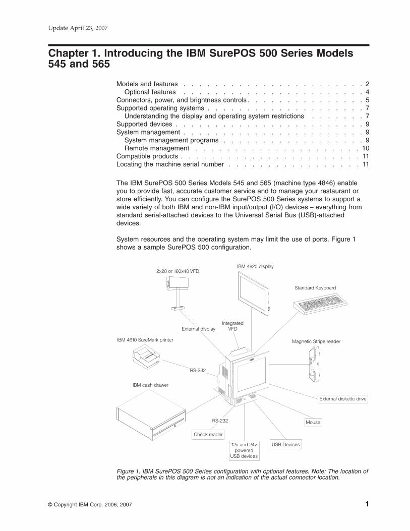
The IBM SurePOS 500 Series Models 545 and 565 (machine type 4846) enable
you to provide fast, accurate customer service and to manage your restaurant or
store efficiently. You can configure the SurePOS 500 Series systems to support a
wide variety of both IBM and non-IBM input/output (I/O) devices – everything from
standard serial-attached devices to the Universal Serial Bus (USB)-attached
devices.
System resources and the operating system may limit the use of ports. Figure 1
shows a sample SurePOS 500 configuration.
External display
Standard Keyboard
2x20 or 160x40 VFD
IntegratedVFD
IBM 4610 SureMark printer
RS-232
IBM cash drawer
RS-232
Magnetic Stripe reader
IBM 4820 display
External diskette drive
Mouse
USB Devices12v and 24vpowered
USB devices
Check reader
Figure 1. IBM SurePOS 500 Series configuration with optional features. Note: The location of
the peripherals in this diagram is not an indication of the actual connector location.
Update April 23, 2007
© Copyright IBM Corp. 2006, 2007 1

Models and features
Table 1 and Table 2 on page 3 summarizes the SurePOS 500 models and features.
Table 1. 4846 Models 545 and 565 summary
Attribute Model 545 Model 565
Processor and FSB speed Intel 326 Celeron D: 2.53 GHz
Chipset Intel 915GV/ICH6
BIOS AwardBIOS
Main memory 512 MB (standard) to 1 GB DDR2 DIMMs
2 slots (2 GB max)
Video Integrated 2D/3D Intel graphics controller for LCD/CRT; Dual independent video option for
CRT (separate data from LCD) with dual video card
LCD
One of the following:
800x600 12.1 in. TFT, High Bright
1024x768 15 in. TFT (2 bulb)
1280x1024 17 in. TFT (4 bulb)
Touch ELO Infra-red
Audio
Not available
AC97 compliant, Codec; amplified stereo
speakers
Mass storage 80 GB SATA II
Modular Flash Drive
LAN Auto sensing 10BaseT/100 BaseTx Ethernet support
Expansion
Not available
PC-Card slot (accommodates PC cards up
to 119 mm long.)
I/O ports and connectors 7 standard USB (3 display tablet, 4 tower rear)
Mouse (rear)
Keyboard (rear)
1, 12V powered USB (rear)
1, 24V powered USB (rear)
2 cash drawer
3 unpowered RS-232
1 powered RS-232 (external customer display)
Head phone (available on Model 565)
Microphone (available on Model 565)
RJ-45 Ethernet LAN
External CRT
I/O devices
External floppy (USB)
MSR (3-track/JUCC)
Integrated 2x20
Distributed 2x20
Distributed APA
Indicators
Power
HDD activity
Ethernet
See Table 3 on page 3 for the status indicator states.
Controls
Power
LCD brightness
Volume (with speaker kit, available on Model 565)
Introducing the SurePOS 500 Models 545 and 565 Update April 23, 2007
2 Models 545 and 565 Hardware Service Guide
||
||||
||
||

Table 2. E and P Models
Model Number Description
4846-E45 System unit Model 545, preloaded with the Windows XP Embedded for Point of
Service (WEPOS)
4846-E65 System unit Model 565, preloaded with the Windows XP Embedded for Point of
Service (WEPOS)
4846-P45 System unit Model 545 with 4610 Printer
4846-P65 System unit Model 565 with 4610 Printer
Table 3. Status indicators
Status/power indicator
On: Logic working correctly. Source AC
power present and within tolerance.
Off: System board defective or power is
off
Blinking during
POST:
Logic malfunction or system in
suspend mode
HDD indicator
On HDD is reading or writing
Off: No HDD activity
Blinking: HDD is reading or writing
Ethernet
Green Left LED states:
v Off - 10 Mbit mode
v On - 100 Mbit
Right LED states
v Off - No link
v On - Good link
v Blinking - Network activity
Introducing the SurePOS 500 Models 545 and 565Update April 23, 2007
Chapter 1. Introducing the IBM SurePOS 500 Series Models 545 and 565 3
|

Optional features
The following is a list of optional features available for the SurePOS 500:
v 4 GB modular flash drive (second drive only)
v Memory:
– 512 MB DDR2 (standard)
– 1 GB DDR2
– 2 GB DDR2, (2 x 1 GB)v Displays:
– Integrated 2x20
– Distributed 2x20
– Distributed APA
– 12-in, 17-in. LCD (15-in. is the standard feature)v MSR:
– 3-track
– JUCCv Countertop/full-size cash drawer integration tray for printer and keyboard
v Countertop integration tray for single station printer, non-keyboard
v Wide cash drawer integration kit for single station printer, non-keyboard
v Cash drawer
v Compact A/N POS (CANPOS) KEYBOARD
v External USB floppy drive
v USB antenna cover (accommodates USB antennas up to 32mm X 101 mm;
excluding the exposed connector)
v Side cover to accommodate PC Card antennas with lengths up to 119 mm
Introducing the SurePOS 500 Models 545 and 565 Update April 23, 2007
4 Models 545 and 565 Hardware Service Guide
|
||
|

Connectors, power, and brightness controls
Figure 2 and Table 4 identifies the controls and tablet connectors.
Table 4. Controls and connectors
Reference Description
�A� MSR port
�B��C��F� USB connectors
�D� Tablet cable connector
�E� Touch cable connector (located behind door)
�G� �H� LCD brightness controls (minus – and plus +)
�I� Power button
Figure 3 on page 6 and Table 5 on page 6 identifies the rear connectors.
BA C D
FI H G E
Figure 2. Tablet connectors
Introducing the SurePOS 500 Models 545 and 565Update April 23, 2007
Chapter 1. Introducing the IBM SurePOS 500 Series Models 545 and 565 5

Table 5. Rear connectors
Reference Description Icon
�J� Serial ports (3), non-powered
12V serial
�L� VGA
�M� Keyboard
�N� Mouse
�O, P� Cash drawer connectors (2
each rated 24 V, 1.0 A 200
ms pulse)
3A, 3B
�Q� Ethernet
�R� Powered 24V rated for 3A
continuous
�S� Powered 12V
�T� USB 2.0 ports (4)
B
J
O
K
P
L M
T
N
RQ S
12v24v
A
B
C
DEF
Ethernet3A 3B
A C D
Figure 3. Rear view of input/output available on all models
Introducing the SurePOS 500 Models 545 and 565 Update April 23, 2007
6 Models 545 and 565 Hardware Service Guide
|||

Supported operating systems
Table 6 describes the operating system support:
Table 6. SurePOS 500 Models 545 and 565 supported operating systems
Supported operating system
Support for Point of Sale
application drivers (MSRs,
customer displays, cash drawers,
tone) Application Driver Notes
PC DOS 2000 Hardware direct interface only
Driver updates are required from
previous SurePOS 500 models. MSR
and Scanner in Wedge mode is not
supported.
Windows 2000, XP
Windows Embedded
Point of Service (WEPOS)¹
Power management via ACPI
Notes:
1. Only DOS full screen mode
supported due to touch screen
alignment requirements.
2. Windows DBCS versions
(Japanese/Korean/Chinese)
supported.
IBM UPOS Drivers for Windows,
Version 1.9.2 or later. (Includes
JavaPOS drivers for Windows and
OPOS drivers.)
Note: ¹The standby and hibernation modes are not supported with WEPOS.
Understanding the display and operating system restrictions
The operating system, the display size, and any attached CRTs can affect the
display resolution. The following definitions describe the terms and various display
configurations:
Single A type of display configuration that supports only one display device.
Twin A type of display configuration that supports two display devices, each of
which has the same content, resolution, and timings. Also referred to as
Simultaneous mode.
Clone A type of display configuration that drives two display devices, each
displaying the same content, but can have different resolutions and
(independent) timings.
Dual Independent Head (DIH)
A type of display configuration that supports two displays with different
content on each display device. Also referred to as an Extended Desktop.
The onboard LCD supports the following modes when using the indicated operating
system:
v DOS: Single
v Windows 2000 and Windows XP: Clone (default), twin
v WEPOS: Clone (default), twin
The onboard LCD and one extra attached LCD:
v DOS: Single; the onboard LCD is primary
v Windows 2000 and Windows XP: Clone (default), twin, DIH
v WEPOS: Clone (default), twin, DIH
Introducing the SurePOS 500 Models 545 and 565Update April 23, 2007
Chapter 1. Introducing the IBM SurePOS 500 Series Models 545 and 565 7
|

Table 7 summarizes the restrictions, if any, imposed by the operating system.
Table 7. Operating system with display combinations and restrictions
Display DOS Windows
Onboard LCD only
Image Single₁ Single
Restrictions None
Onboard LCD +
external display
Image Single Dual-same
Restrictions External display not
supported
Media clips show on
onboard LCD only;
External display must
be the same resolution
as onboard LCD
Onboard LCD +
Add-in video card
Image Single, on board LCD Dual-independent₂
Restrictions None Onboard LCD
becomes secondary
display when installing
Windows
General
Restrictions Touch on primary
display only
None
1. Dual-same: same data on both displays; simultaneous mode
2. Dual-independent; different/independent data on both displays; extended
desktop
Table 8. Supported video resolutions in Windows operating system
LCD size Available video resolutions for onboard LCD
12 in. 640 x 480, 720 x 480, 800 x 600
15 in. 640 x 480, 720 x 480, 800 x 600,
960 x 540, 1024 x 768
17 in. 640 x 480, 720 x 480, 800 x 600,
960 x 540, 1024 x 768, 1152 x 864,
1280 x 720, 1280 x 768, 1280 x 960, 1280 x 1024
Introducing the SurePOS 500 Models 545 and 565 Update April 23, 2007
8 Models 545 and 565 Hardware Service Guide
|
||||

Supported devices
Table 9 summarizes the industry standard devices that have been tested with the
product. Other industry devices may be supported using standard interfaces;
however, no testing was performed to insure functionality in all aspects of operation.
Table 9. Summary of tested and supported devices
Port type Supported device Hot plug support (See note 1)
RS-232 (Serial) v 4610 TF6/TF7 single station
thermal printer
v 4610-TG3, TG4, TG5
Not supported
CRT (Video) v 4820-4FD/4FT with MSR option,
USB
v 4820 - 1GD, 2GN, 2GD, 2GB
Not supported
USB v 4610-GB3
v 4610-TG3/TG4/TG5
v IBM USB floppy drive
v IBM USB keyboard
v IBM Memory key
v IBM 4685-S01/L0h handheld
scanner
Yes; however, USB not supported on
DOS; powered USB ports is not
supported.
Keyboard/Mouse v IBM PS/2 keyboard
v IBM mouse
v Retail CANPOS keyboard (See
note 2.)
Yes for USB devices
No for PS/2 devices
PC Card v See the IBM web site
(www.ibm.com/solutions/retail/store/) for tested devices.
Yes
Headphone/microphone v IBM or equivalent
Yes
Notes:
1. Assumes device natively supports hot plugging and can be hot plugged with any operating system.
2. CANPOS MSR option is mutually exclusive for SurePOS 500 Models 545 and 565.
3. Some PCMCIA devices may require third party software support.
System management
This section describes the types of system management available with the
SurePOS 500.
System management programs
The SurePOS 500 Series supports the following system and power management
programs:
Desktop Management Interface
The SurePOS 500 Series supports System Management BIOS (SMBIOS)
v2.4, supporting a DMI-compliant agent such as Tivoli®. This allows access
to low-level information. Examples of information that can be accessed are
the BIOS level, processor type, speed, manufacturer, system-board
information, and detailed memory information.
Introducing the SurePOS 500 Models 545 and 565Update April 23, 2007
Chapter 1. Introducing the IBM SurePOS 500 Series Models 545 and 565 9
||

RDM (Remote Deployment Manager) and IBM Director.
RDM can install an OS and update BIOS remotely and probe machines for
low-level information. IBM Director can remotely configure applications and
operating systems, transfer files, and inventory workstations on a network.
APM APM consists of several layers of software that allow the operating system,
applications, and BIOS to work together to reduce power consumption.
APM is supported on DOS and Linux platforms.
Advanced Configuration and Power Interface
Advanced Configuration and Power Interface (ACPI) V1.0 defines a
hardware and software interface and tables by which the operating system
can alter the characteristics of the hardware-specific devices. ACPI is
supported on Windows 2000 and Windows XP.
Power up on LAN
This feature enables the system to power on when it receives a specific
frame over the local area network (LAN) through the 10/100-Mbps Ethernet
feature. You can enable power up (wake) on LAN by enabling Wake on
LAN in the CMOS Setup Utility program.
Power up (wake) on daily alarm
This feature enables the system to turn on at the same time every day. You
can enable power up (wake) on daily alarm by enabling Wake on Alarm in
the CMOS Setup Utility program.
RMA IBM Remote Management Agent is a component of IBM Store Integration
Framework that simplifies the delivery of new consumer-facing devices in
stores to support the delivery of superior service. For more information, see
the Retail Store Solutions web site.
Remote management
The SurePOS 500 Models 545 and 565 supports remote system management over
the network. The following functions are supported:
v Selectable startup sequence
v Update POST/BIOS from the network
v Ethernet
v Power up (wake) on LAN
Introducing the SurePOS 500 Models 545 and 565 Update April 23, 2007
10 Models 545 and 565 Hardware Service Guide

Compatible products
You can use the following products with the SurePOS 500:
v 4610 SureMark Single Station Thermal Printer (RS-232 models)
v 4610 SureMark Printer
v 4820 SurePoint Solution Terminal
v IBM point-of-sale USB devices
v Original equipment manufacturer (OEM) USB devices
v OEM RS-232 Point of Sale devices (printers, 2x20, and others)
v OEM USB printers
v CRT/LCD displays
v IBM USB portable CD-ROM drive
v IBM USB 2.0 CD-RW/DVD-ROM drive
v TEAC USB CD-ROM drive
Locating the machine serial number
The serial number and model number (�A� in Figure 4) are located under the front
cover/HDD cover. �B� points to the tablet size label.
B
A
Figure 4. Serial number location
Introducing the SurePOS 500 Models 545 and 565Update April 23, 2007
Chapter 1. Introducing the IBM SurePOS 500 Series Models 545 and 565 11

Update April 23, 2007
12 Models 545 and 565 Hardware Service Guide

Chapter 2. Running diagnostics and troubleshooting
Using the CMOS Setup Utility . . . . . . . . . . . . . . . . . . . 13
Using the Main window . . . . . . . . . . . . . . . . . . . . . 13
Standard CMOS features . . . . . . . . . . . . . . . . . . . 14
Advanced BIOS features . . . . . . . . . . . . . . . . . . . 14
Integrated peripherals . . . . . . . . . . . . . . . . . . . . 14
Power Management . . . . . . . . . . . . . . . . . . . . . 14
PnP/PCI Configurations . . . . . . . . . . . . . . . . . . . . 14
PC Health Status . . . . . . . . . . . . . . . . . . . . . . 15
Load Defaults . . . . . . . . . . . . . . . . . . . . . . . 15
Set Password . . . . . . . . . . . . . . . . . . . . . . . 15
Restoring the default CMOS settings . . . . . . . . . . . . . . . . 15
Clearing the CMOS settings . . . . . . . . . . . . . . . . . . . 15
Real-time clock and CMOS . . . . . . . . . . . . . . . . . . . 16
Configuring the COM (communication) ports . . . . . . . . . . . . . 16
Using the IBM Diagnostics for POS Systems and Peripherals package . . . . 16
Supported memory keys . . . . . . . . . . . . . . . . . . . . 17
Updating the flash BIOS . . . . . . . . . . . . . . . . . . . . . 17
Power interruption during flash BIOS update procedure . . . . . . . . . 18
Repairing the flash BIOS . . . . . . . . . . . . . . . . . . . . 18
Diagnosing problems and troubleshooting . . . . . . . . . . . . . . . 19
Researching the Knowledgebase . . . . . . . . . . . . . . . . . 19
Preliminary checklist . . . . . . . . . . . . . . . . . . . . . . 19
Troubleshooting symptoms and actions . . . . . . . . . . . . . . . 20
CMOS recovery . . . . . . . . . . . . . . . . . . . . . . . . 23
Using the CMOS Setup Utility
Follow these steps to start the CMOS Setup Utility:
1. Switch the power ON.
2. Press Del during POST when prompted, or tap the touch screen two times.
Use the keys listed in the legend bar at the bottom of the screen to make your
selections or exit from the current menu. The help window on the right side of
each menu displays the online help information for the currently selected item.
Figure 5 on page 14 is an example of the initial panel that is displayed in the CMOS
Setup Utility.
Using the Main window
Use the Main window (Figure 5 on page 14) to access the various features of the
CMOS utility. The navigation tool bar is located at the bottom of the screen.
Update April 23, 2007
© Copyright IBM Corp. 2006, 2007 13

Standard CMOS features
This menu provides basic functions, like setting the time and date. It also provides
basic information, such as BIOS version, Ethernet MAC address, memory size, and
machine serial number.
To change the date, month, and time using the CMOS Utility,
1. With the month entry highlighted (in red), touch the red numeric keyboard to
indicate the current month. For example, enter 8 to change the month to Aug.
2. Touch enter. The correct month appears as text.
3. Using the displayed keyboard, enter the number of the month. For example,
enter 8 for August, or 1 for January, and select Enter.
Advanced BIOS features
The Advanced BIOS window allows you to modify the POST and boot device
settings, and set the keyboard features.
Integrated peripherals
Using this menu you can configure I/O devices, such as serial ports, Ethernet,
parallel port, USB controller, and keyboard.
Power Management
Use the Power Management window to configure Wake on Ring, the power
savings, hard disk time-out, video time-out, and other power settings.
Wake on Ring: Use the Power Management Setup menu to enable the Wake on
Ring feature. Wake on Ring allows a modem attached to Serial Port D to wake the
system using Ring Indicate. Additionally, the tailgate card contains jumpers for
ports A-C to optionally associate DSR (pin 1) to Ring Indicate.
PnP/PCI Configurations
This option allows advanced functions for PCI configuration data.
Figure 5. CMOS Setup Utility main window
Update April 23, 2007
14 Models 545 and 565 Hardware Service Guide
PC Health Status
This is an information window that provides the CPU and system temperatures,
voltages on the system board, and fan speed.
Load Defaults
This selection resets all options to their default configuration.
Set Password
Use the password options menu to set, change, or clear the system password.
Restoring the default CMOS settings
To restore CMOS default settings, select Load Optimized Settings from the main
menu.
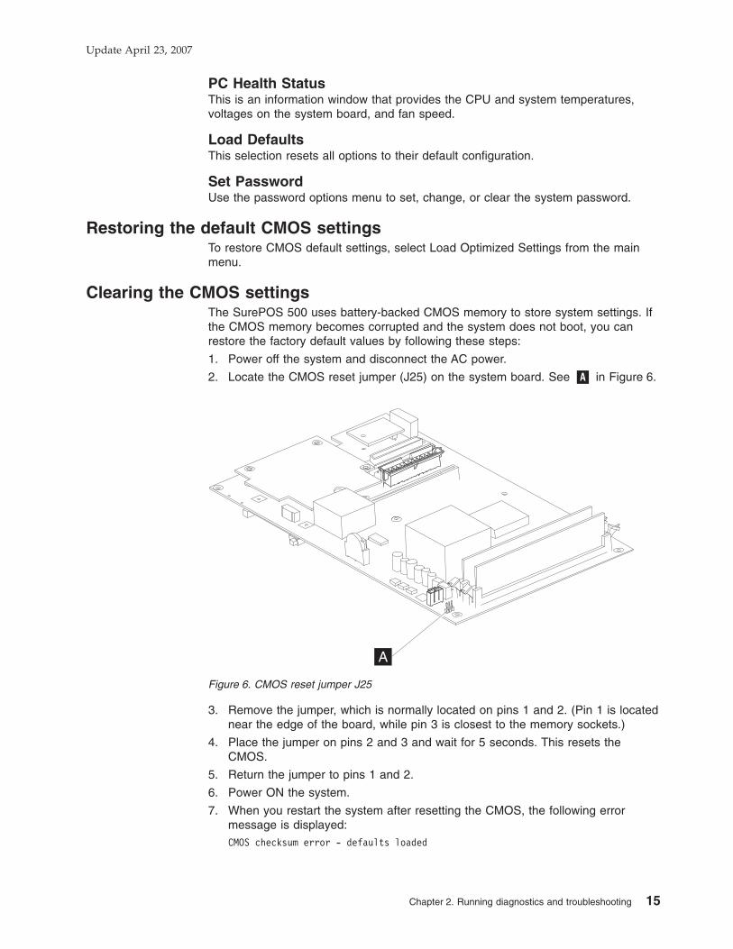
Clearing the CMOS settings
The SurePOS 500 uses battery-backed CMOS memory to store system settings. If
the CMOS memory becomes corrupted and the system does not boot, you can
restore the factory default values by following these steps:
1. Power off the system and disconnect the AC power.
2. Locate the CMOS reset jumper (J25) on the system board. See �A� in Figure 6.
3. Remove the jumper, which is normally located on pins 1 and 2. (Pin 1 is located
near the edge of the board, while pin 3 is closest to the memory sockets.)
4. Place the jumper on pins 2 and 3 and wait for 5 seconds. This resets the
CMOS.
5. Return the jumper to pins 1 and 2.
6. Power ON the system.
7. When you restart the system after resetting the CMOS, the following error
message is displayed:
CMOS checksum error - defaults loaded
A
Figure 6. CMOS reset jumper J25
Update April 23, 2007
Chapter 2. Running diagnostics and troubleshooting 15

To correct these errors, run the Setup Utility and select Load Optimized
Defaults. This restores the CMOS defaults. After the defaults are restored,
check the date and time, and set any other customer-specific settings that were
modified before the CMOS was reset.
Real-time clock and CMOS
The real-time clock is a low-power clock that provides a time-of-day clock and a
calendar. The clock settings are maintained by the battery when the power cord is
removed. Use the CMOS Setup Utility to set the clock and calendar. See “Standard
CMOS features” on page 14.
See “System-board battery – removing and replacing” on page 52 for the location of
the battery.
Configuring the COM (communication) ports
Each COM port of the 4846 product uses a unique I/O address and IRQ. Some
previous SurePOS 500 system units utilized PCI-based COM ports with a shared
IRQ. The system BIOS configures the COM ports for use by the operating system;
therefore, a separate driver is not required. (Serial port drivers from previous
SurePOS 500 systems are not supported or required.)
Use the CMOS Setup Utility to configure or modify the COM ports, the default I/O
address and the IRQ. If you make modifications, ensure that each port uses a
unique I/O and IRQ value. Using default values are highly recommended. The IBM
SurePOS 500 Series Operating System Installation Guide for Models 545 and 565
provides a list of port resources.
Using the IBM Diagnostics for POS Systems and Peripherals package
Diagnostics for the SurePOS 500 Models 545 and 565 are available on the IBM
Diagnostics for POS Systems and Peripherals package. This package installs to a
memory key (see “Supported memory keys” on page 17).
Note: The Diagnostics also supports IBM POS I/O on prior systems, if the BIOS
supports booting from a memory key.
Locate the instructions for using this package in the README file. This package
provides menu-driven tests and utilities that enable trained service technicians to
configure and test the I/O devices. Locate and download the service program code
from the IBM Retail Store Solutions Web site using the following steps:
1. Obtain a memory key. See “Supported memory keys” on page 17.
2. Access the IBM Retail Store Solutions Web site at: www.ibm.com/solutions/retail/store/support.
3. Select Support on the left side of the panel, then select IBM SurePOS 500/600
Series.
4. Next, select SurePOS 500-xx5 Downloads.
5. Download the update program to a temporary location on the PC’s hard-disk
drive. Run the self-extracting program and respond to the messages that
display. This program writes the updates and provides instructions on inserting
the memory key.
Update April 23, 2007
16 Models 545 and 565 Hardware Service Guide

6. If you have not previously changed the CMOS Utility settings, you can boot into
the diagnostics using the USB memory key: Insert the USB memory key and
power on the system. If you have previously changed the default settings, go to
Step 7.
7. If you have changed the default settings of the CMOS Setup Utility, follow these
steps:
a. Ensure that the Hard Disk is listed as the First Book Device under
Advanced BIOS Features, Hard Disk Boot Priority.
b. Power off the machine.
c. Plug the memory key into a USB port.
d. Power on the machine. The system BIOS recognizes the memory key and
adds it to the lists displayed by the CMOS Setup Utility.
e. Open the CMOS Setup Utility settings. Ensure that your settings are as
follows:
v Under Advanced BIOS Features, Hard Disk Boot Priority, ensure that
memory key is listed first.
v Under First Boot Device, ensure that Hard Disk is listed first.
f. Save these settings and exit. The system will boot automatically using the
memory key and the diagnostics program begins.
You have the option of using an attached keyboard, if available. The diagnostics
program will ask you to accept the user license agreement. Click the I Agree
button. You will be presented with a screen containing a selection menu for System
Components, Point Of Sale Devices, and Utilities (for VPD, and others). Sub-menus
are dynamically-tailored based upon your system—only tests available for your
machine type are displayed.
Supported memory keys
The following memory keys are supported by the SurePOS 500 Models 545 and
565:
IBM USB 2.0 (256 MB)
v FRU: 41D9746
Go to www.ibm.com for details on this USB key.
PNY USB 2.0 (1 GB)
v Part number: P1886C53
Go to http://www2.pny.com/homepage.aspx for details on this USB key.
Updating the flash BIOS
Download the latest level of flash BIOS for the SurePOS 500 Models 545 and 565
by following the instructions for downloading the diagnostics.
1. Follow the steps described in “Using the IBM Diagnostics for POS Systems and
Peripherals package” on page 16
2. Switch the system ON again. The system boots from the memory key, the flash
BIOS update occurs.
3. Remove the memory key. The new BIOS update is on the system.
Note: The flash utility saves and restores your CMOS setting.
Update April 23, 2007
Chapter 2. Running diagnostics and troubleshooting 17

Power interruption during flash BIOS update procedure
If power is interrupted during the flash BIOS update procedure, the BIOS could
become corrupted. Should this event occur, the system boots automatically from a
backup copy of BIOS. To repair the corrupt version of BIOS and return to using the
normal BIOS, repeat the steps to update the flash BIOS.
Repairing the flash BIOS
Two separate copies of POST/BIOS are maintained in separate flash modules.
Should the primary copy become corrupt, the system automatically runs from the
backup copy when rebooted. A POST message indicates when the backup copy is
in use. When this happens, it is important to perform a Flash Update, in an attempt
to repair the primary copy and preserve the backup functionality. If the primary is
permanently damaged, the system runs normally, but without backup capability for
the BIOS, and the POST message appears at each boot up.
Update April 23, 2007
18 Models 545 and 565 Hardware Service Guide
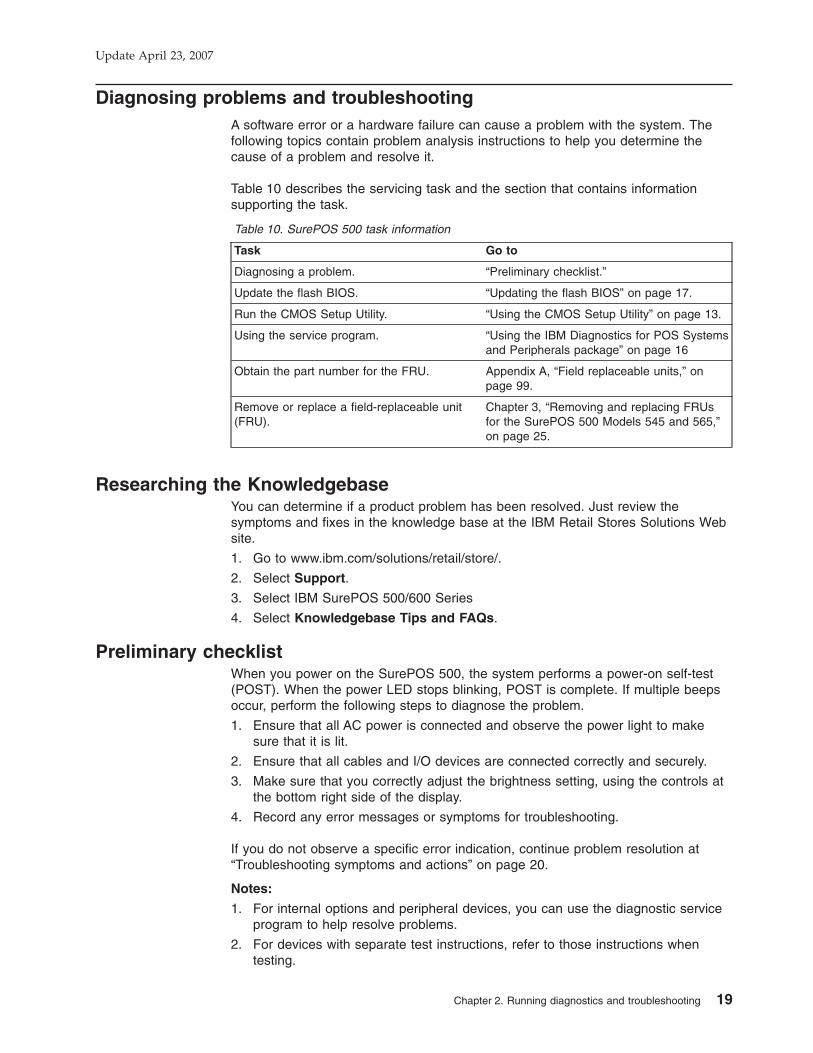
Diagnosing problems and troubleshooting
A software error or a hardware failure can cause a problem with the system. The
following topics contain problem analysis instructions to help you determine the
cause of a problem and resolve it.
Table 10 describes the servicing task and the section that contains information
supporting the task.
Table 10. SurePOS 500 task information
Task Go to
Diagnosing a problem. “Preliminary checklist.”
Update the flash BIOS. “Updating the flash BIOS” on page 17.
Run the CMOS Setup Utility. “Using the CMOS Setup Utility” on page 13.
Using the service program. “Using the IBM Diagnostics for POS Systems
and Peripherals package” on page 16
Obtain the part number for the FRU. Appendix A, “Field replaceable units,” on
page 99.
Remove or replace a field-replaceable unit
(FRU).
Chapter 3, “Removing and replacing FRUs
for the SurePOS 500 Models 545 and 565,”
on page 25.
Researching the Knowledgebase
You can determine if a product problem has been resolved. Just review the
symptoms and fixes in the knowledge base at the IBM Retail Stores Solutions Web
site.
1. Go to www.ibm.com/solutions/retail/store/.
2. Select Support.
3. Select IBM SurePOS 500/600 Series
4. Select Knowledgebase Tips and FAQs.
Preliminary checklist
When you power on the SurePOS 500, the system performs a power-on self-test
(POST). When the power LED stops blinking, POST is complete. If multiple beeps
occur, perform the following steps to diagnose the problem.
1. Ensure that all AC power is connected and observe the power light to make
sure that it is lit.
2. Ensure that all cables and I/O devices are connected correctly and securely.
3. Make sure that you correctly adjust the brightness setting, using the controls at
the bottom right side of the display.
4. Record any error messages or symptoms for troubleshooting.
If you do not observe a specific error indication, continue problem resolution at
“Troubleshooting symptoms and actions” on page 20.
Notes:
1. For internal options and peripheral devices, you can use the diagnostic service
program to help resolve problems.
2. For devices with separate test instructions, refer to those instructions when
testing.
Update April 23, 2007
Chapter 2. Running diagnostics and troubleshooting 19

3. When using application software, you may receive error messages that pertain
to the software. Refer to the software manual for a description of those
messages.
Troubleshooting symptoms and actions
If the SurePOS 500 system fails with no error message or beep code, see Table 11
to find problem symptoms and take the related action.
Note: Corrupted CMOS may cause unpredictable problems. Before exchanging the
system board to resolve a problem, go to “Clearing the CMOS settings” on
page 15 and reset CMOS. Oftentimes, a corrupted CMOS is the source of
the trouble.
Table 11. Symptoms and actions
If the problem is... Here’s what to do.
No power light on the tower unit. 1. Ensure that the system unit is plugged into a working electrical outlet and
replug the power cable at the power supply.
2. Verify that the tablet display cable is plugged into the tablet.
3. Verify that the button/LED card in the tablet is plugged in properly.
4. Verify the power supply is properly installed.
5. Replace the power supply. See “Power supply – removing and replacing”
on page 46.
6. Replace the system board. See “System board – removing and replacing”
on page 50.
Operator display exhibits:
Blank screen
No cursor displayed
Screen is unreadable
Other display problems.
1. Adjust the brightness control at the bottom right side of the display.
2. Ensure that the tablet display cable is securely connected.
3. Switch the unit off and the power on.
4. Run the operator display test using the diagnostic service program.
5. Replace the LCD assembly. See “Front bezel and LCD assembly -
removing and replacing” on page 37.
6. Replace the system board. See “System board – removing and replacing”
on page 50.
For details on cash drawer removal and replacement procedures, see the IBM Point of Sale Options and I/O Devices
Service Guide, GC30-9737. Throughout this text, this book is referred to as the I/O book.
Cash drawer does not open when
cash drawer key is turned to the open
position.
1. Replace the keylock insert if the lock does not turn with the key. See the
I/O book.
2. Gently pull the drawer open while holding the key turned to the open
position to determine if the slide assembly is binding. Look for items that
may cause binds, such as pens or paper clips. Replace the slide
assembly if necessary.
3. Replace the cam, pawl, and spring kit.
4. Check for a bent actuator rod. Replace the actuator rod if necessary.
Cash drawer does not stay closed. 1. Make sure that the keylock is not bound in the open position. Replace the
keylock if necessary.
2. Replace the cam, pawl, and spring kit.
3. Replace the latch and the sensor assembly card.
4. Replace the cash drawer.
5. Replace the system board. See “System board – removing and replacing”
on page 50.
Update April 23, 2007
20 Models 545 and 565 Hardware Service Guide

Table 11. Symptoms and actions (continued)
Cash drawer does not open or close
smoothly, or appears to be binding.
1. Look for items that could cause binding. Pens or paper clips trapped
between the drawer and cover or the drawer and base could cause
binding.
2. Compact drawer only: Remove the drawer and the rollers at the rear of
the drawer and at the front of the base. Replace the rollers if necessary.
3. Determine if the slide assembly in the base is binding. Replace the slide
assembly if necessary.
Cash drawer not opening 1. Run the CMOS Setup Utility to make sure that IBM cash drawer setting is
enabled.
2. Ensure that the cash drawer cable is securely connected.
3. Replace the cash drawer cable.
4. Replace the cash drawer latch assembly.
5. Replace the system board.
Cash drawer does not open when
performing store transactions or
running cash drawer tests, but it opens
when the cash drawer key is turned to
the open position.
1. Replace the latch and the sensor assembly card.
2. Replace the cash drawer cable.
3. Replace the system board. See “System board – removing and replacing”
on page 50.
The status displayed by the cash
drawer tests does not match the
physical status of the cash drawer
being tested. For example, the test
indicates that cash drawer A is closed
when cash drawer A is actually open.
1. Replace cable.
2. Replace the latch and the sensor assembly card.
3. Replace the system board. See “System board – removing and replacing”
on page 50.
Magnetic stripe reader (MSR) not
reading.
1. Check the three-track MSR dip switch settings for either RS232 or
keyboard interface.
2. Run the CMOS Setup Utility and check the setting in the MSR serial port.
3. Ensure that the MSR cable is securely connected.
4. Run the MSR test using the diagnostic service program.
5. Reset to factory defaults by pressing the Reset button with a paper clip.
The MSR must be removed temporarily from the side of the tablet to
access the reset button. Leave the MSR cable connected, and the unit
powered ON when pressing the Reset button.
6. Replace the MSR. See “Magnetic stripe reader (MSR) – removing and
replacing” on page 59.
Operator display backlight: dark, dim,
or partially lit.
1. Adjust the brightness using the button located on the front of the display.
2. Ensure tablet display cable is securely attached under display tablet and
at system board.
3. Replace the LCD assembly, see “Front bezel and LCD assembly -
removing and replacing” on page 37.
Touch screen not working. 1. Ensure tablet display cable is securely attached under display tablet and
at system board.
2. Run the touch screen test using the diagnostic service program.
3. Reinstall the touch driver.
4. Replace the front touch bezel assembly. See “Front bezel and LCD
assembly - removing and replacing” on page 37.
5. Replace the system board. See “System board – removing and replacing”
on page 50.
Update April 23, 2007
Chapter 2. Running diagnostics and troubleshooting 21

Table 11. Symptoms and actions (continued)
PS/2 keyboard does not work or only
some keys work.
1. Ensure that the keyboard cable is securely connected.
2. Move your fingers across the keys, making sure that no keys are stuck.
3. Ensure that you are on a window that allows typing. Some windows do
not allow you to type on them.
4. Run the keyboard test from the diagnostics program.
5. Replace the keyboard.
Diskette drive does not work. 1. Check the diskette drive cable connections.
2. Run the CMOS Setup Utility to make sure the diskette drive controller is
enabled.
3. Ensure that the correct boot device is selected in the CMOS Setup Utility,
which is USB–FDD.
4. Verify the hardware by attempting to load a bootable diskette.
5. If the drive will not boot with a bootable diskette, replace the drive and
cable.
6. Replace the system board.
Audio is not working. 1. Check the volume control.
2. Check the speaker cable connections.
3. Run CMOS Setup Utility to make sure the audio is enabled.
4. Replace the speaker.
5. Replace the system board.
Fan continues running after system
has been powered Off.
This is normal operation with the power supplies.
Notes:
1. Some devices that attach to the system have test instructions. Refer to those
instructions when testing those devices.
2. Record any error messages or symptoms for future reference.
3. When using application programs, you may receive error messages that pertain
to the application software. See the application program manual for a
description of those messages.
Update April 23, 2007
22 Models 545 and 565 Hardware Service Guide

CMOS recovery
If the CMOS memory becomes corrupted and the system does not boot, restore the
factory default values by following the procedure described in “Clearing the CMOS
settings” on page 15.
Always reset CMOS (as described at “Restoring the default CMOS settings” on
page 15) before replacing a system board to resolve a problem. This practice
allows you to determine if a corrupted CMOS is the source of the trouble. A
corrupted CMOS can cause unpredictable problems.
Update April 23, 2007
Chapter 2. Running diagnostics and troubleshooting 23

Update April 23, 2007
24 Models 545 and 565 Hardware Service Guide

Chapter 3. Removing and replacing FRUs for the SurePOS
500 Models 545 and 565
Opening and removing covers and assemblies . . . . . . . . . . . . . 26
Handling static-sensitive devices . . . . . . . . . . . . . . . . . . 28
Modular service tools . . . . . . . . . . . . . . . . . . . . . 29
Removing the covers . . . . . . . . . . . . . . . . . . . . . . 30
Front (or HDD) cover removal . . . . . . . . . . . . . . . . . . 30
Rear cover removal . . . . . . . . . . . . . . . . . . . . . . 31
Opening the I/O tailgate cover . . . . . . . . . . . . . . . . . . 32
Top cover removal . . . . . . . . . . . . . . . . . . . . . . 33
Hinge cover removal . . . . . . . . . . . . . . . . . . . . . . 34
Display tablet - removing and replacing . . . . . . . . . . . . . . . . 35
Display tablet cable – removing and replacing . . . . . . . . . . . . 36
Front bezel and LCD assembly - removing and replacing . . . . . . . . . 37
Operator card - removing and replacing . . . . . . . . . . . . . . . 39
Tablet hinge assembly – removing and replacing . . . . . . . . . . . . 40
Hard disk drive and bracket – removing and replacing . . . . . . . . . . 41
Hard disk drive fan and bracket – removing and replacing . . . . . . . . . 43
Hard disk drive cables – removing and replacing . . . . . . . . . . . . 44
Cable tie bar – removing and replacing . . . . . . . . . . . . . . . . 45
Power supply – removing and replacing . . . . . . . . . . . . . . . . 46
Power supply latch arm – removing and replacing . . . . . . . . . . . . 47
Rear connector panel (tailgate) – removing and replacing . . . . . . . . . 48
System board – removing and replacing . . . . . . . . . . . . . . . 50
System-board jumper location and settings . . . . . . . . . . . . . 52
System-board battery – removing and replacing . . . . . . . . . . . . 52
Processor fan/heatsink assembly - removing and replacing . . . . . . . 54
Processor module – removing and replacing . . . . . . . . . . . . . 55
Memory modules – removing and replacing . . . . . . . . . . . . . . 56
Memory modules and industry standards . . . . . . . . . . . . . . 57
Base plate – removing and replacing . . . . . . . . . . . . . . . . . 58
Optional features . . . . . . . . . . . . . . . . . . . . . . . . 59
Magnetic stripe reader (MSR) – removing and replacing . . . . . . . . . 59
MSR hole plug – removing and replacing . . . . . . . . . . . . . . 60
PC card blank – removing . . . . . . . . . . . . . . . . . . . . 60
PC card – removing and replacing . . . . . . . . . . . . . . . . . 61
Video adapter card– removing and replacing . . . . . . . . . . . . . 63
Speaker – removing and replacing . . . . . . . . . . . . . . . . . 64
Integrated customer display – removing and replacing . . . . . . . . . 66
Modular flash drive – removing and replacing . . . . . . . . . . . . 67
This section contains the FRU removal and replacement procedures for all
SurePOS 500 Models 545 and 565 models (4846). Some procedures are for
features that are not available on all models.
Notes:
1. Before you perform any removal and replacement procedures, see the sections
entitled “Safety Information” on page xi and “Handling static-sensitive devices”
on page 28.
2. The machine serial number for the 4846 is located on the lower right, front
frame. See Figure 4 on page 11.
3. Switch OFF the power to the SurePOS 500. Unplug the power cord from the
external power source.
Update April 23, 2007
© Copyright IBM Corp. 2006, 2007 25
||
||
||

Opening and removing covers and assemblies
The SurePOS 500 Series Models 545 and 565 is designed for modular servicing
and installation. Table 12 shows the progression and ease of some common
removals.
Table 12. Pictorial overview of common removal tasks
Task: Section with complete details:
Opening the rear cover “Rear cover removal” on page 31
Removing the power supply “Power supply – removing and replacing” on
page 46
Opening the tailgate “Rear connector panel (tailgate) – removing
and replacing” on page 48
Removing the tailgate
Removing and replacing FRUs Update April 23, 2007
26 Models 545 and 565 Hardware Service Guide

Table 12. Pictorial overview of common removal tasks (continued)
Task: Section with complete details:
Removing the top cover “Top cover removal” on page 33
Removing the system board “System board – removing and replacing” on
page 50
Opening the front cover “Front (or HDD) cover removal” on page 30
Removing the hard-disk drive “Hard disk drive and bracket – removing and
replacing” on page 41
Removing and replacing FRUsUpdate April 23, 2007
Chapter 3. Removing and replacing FRUs for the SurePOS 500 Models 545 and 565 27

Table 12. Pictorial overview of common removal tasks (continued)
Task: Section with complete details:
Opening the touch-cable cover “Front bezel and LCD assembly - removing
and replacing” on page 37
Removing the front bezel
Note: These pictures represent only some of the common component removals.
Handling static-sensitive devices
Attention: Static electricity can damage electronic devices and your system. To
avoid damage, keep static-sensitive devices in their static protective bags until you
are ready to install them.
To reduce the possibility of electrostatic discharge, observe the following
precautions:
v Limit your movement. Movement can cause static electricity to build up around
you.
v Handle the device carefully, holding it by its edges or its frame.
v Do not touch solder joints, pins, or exposed printed circuitry.
v Do not leave the device where others can handle and possibly damage the
device.
v While the device is contained in its anti-static bag, touch it and your finger to an
unpainted metal part of the system unit for at least 2 seconds. (This action
removes static electricity from the package and from your body.)
v Remove the device from its package and install it directly into your system,
without putting it down. If it is necessary to put the device down, place it onto its
static-protective bag. (If your device is an adapter, place it component side up.)
Do not place the device onto the cover of the system or onto a metal table.
v Take additional care when handling devices during cold weather because heating
reduces indoor humidity and increases static electricity.
Removing and replacing FRUs Update April 23, 2007
28 Models 545 and 565 Hardware Service Guide

Modular service tools
The SurePOS 500 Models 545 and 565 were designed for modular servicing and
requires the minimum use of tools. However, some field replacement parts may
require a tool. Table 13 lists the part number for tools that you may need for
servicing.
Table 13. Service personnel tools
Description Part Number Units
Wrap plug, Ethernet 03N6070 1
Wrap plug, RS-232 72X8546 1
Adapter cable, RJ-45 to 9-pin
conversion
40N5341 1
Removing and replacing FRUsUpdate April 23, 2007
Chapter 3. Removing and replacing FRUs for the SurePOS 500 Models 545 and 565 29
|
|

Removing the covers
This section describes how to remove the front, top, rear, tower, and side covers.
Front (or HDD) cover removal
1. Switch OFF the power to the SurePOS 500. Unplug the power cord from the
external power source.
2. Tilt the top of the display tablet back.
3. Press inward on the buttons on each side of the front cover (see Figure 7), and
pull the front cover/HDD cover slightly forward.
4. Lift the cover forward and away from the unit.
5. To replace, reverse these procedures.
Figure 7. Unlatching the front cover
Removing and replacing FRUs Update April 23, 2007
30 Models 545 and 565 Hardware Service Guide
|
|||
|||

Rear cover removal
1. Switch OFF the power to the SurePOS 500. Unplug the power cord from the
external power source.
2. Facing the rear of the system, press down on the latch �A�, and rotate the top
away as shown in Figure 8, and lift the rear cover away from the unit.
3. To replace, reverse these procedures.
A
Figure 8. Removing the rear cover
Removing and replacing FRUsUpdate April 23, 2007
Chapter 3. Removing and replacing FRUs for the SurePOS 500 Models 545 and 565 31
|

Opening the I/O tailgate cover
Open the I/O tailgate cover as follows:
v Remove the rear cover as described in “Rear cover removal” on page 31.
v Unlatch the I/O tailgate cover by sliding the latches (�A� in Figure 9) toward the
center.
v Open the I/O tailgate cover by rotating it downward.
A
Figure 9. Opening the I/O tailgate cover
Removing and replacing FRUs Update April 23, 2007
32 Models 545 and 565 Hardware Service Guide

Top cover removal
1. Switch OFF the power to the SurePOS 500. Unplug the power cord from the
external power source.
2. Remove the rear cover, following the procedure in “Rear cover removal” on
page 31.
3. Open the I/O tailgate cover (see “Opening the I/O tailgate cover” on page 32).
4. Facing the rear of the system, use a screwdriver to lift the latch (�A�in
Figure 10), while sliding the top cover toward you (toward the rear of the unit)
5. Repeat for the latch on the other side.
6. To replace, slide the top cover on from the rear.
A
Figure 10. Locating the top cover release latch
Removing and replacing FRUsUpdate April 23, 2007
Chapter 3. Removing and replacing FRUs for the SurePOS 500 Models 545 and 565 33

Hinge cover removal
1. Switch OFF the power to the SurePOS 500. Unplug the power cord from the
external power source.
2. Remove the display tablet. See “Display tablet - removing and replacing” on
page 35.
3. Remove the HDD or front cover. See “Front (or HDD) cover removal” on page
30
4. Remove the top cover as described in “Top cover removal” on page 33.
5. Remove the center cover (�C�) by lifting it off.
6. Lift off to remove the hinge cover (�D�).
Note: You will need to pull the sides of the hinge cover away from the hinge so
that features (�E�) will clear holes (�F� in Figure 11).
C
F
E
D
Figure 11. Removing the hinge cover
Removing and replacing FRUs Update April 23, 2007
34 Models 545 and 565 Hardware Service Guide

Display tablet - removing and replacing
Follow these procedures to remove the display tablet.
1. Switch OFF the power to the SurePOS 500. Unplug the power cord from the
external power source.
2. Tilt the tablet back and loosen the two thumbscrews �A� in Figure 12 under the
tablet.
3. If present, unplug the MSR cable.
4. Disconnect the cable from the rear of the tablet by pressing on either side of the
connector.
5. Lift the tablet off the unit.
6. To replace, reverse these procedures.
A
Figure 12. Removing the display tablet
Removing and replacing FRUsUpdate April 23, 2007
Chapter 3. Removing and replacing FRUs for the SurePOS 500 Models 545 and 565 35

Display tablet cable – removing and replacing
1. Switch OFF the power to the SurePOS 500. Unplug the power cord from the
external power source.
2. Remove the tablet as described in “Display tablet - removing and replacing” on
page 35.
3. Disconnect the display cable from the rear of the tablet by pressing on either
side of the connector.
4. Remove the front cover as described “Front (or HDD) cover removal” on page
30.
5. Remove the speaker, if present. See “Speaker – removing and replacing” on
page 64.
6. Remove the rear cover as described in “Rear cover removal” on page 31.
7. Remove the power supply as described in “Power supply – removing and
replacing” on page 46.
8. Remove the clamps on front of the frame and hinge that retain the tablet
cable.
9. Disconnect the display tablet cable from the system board by loosening the
two thumbscrews (see Figure 13).
10. Remove the base plate. See “Base plate – removing and replacing” on page
58.
11. Pull the cable free from the plastic guide in the frame.
12. To replace, reverse these procedures.
Figure 13. Removing the display tablet cable from the system board
Removing and replacing FRUs Update April 23, 2007
36 Models 545 and 565 Hardware Service Guide
|
|||
|
||
||
||
||
||
|
|||
||
||
||
|
|

Front bezel and LCD assembly - removing and replacing
Note: The front bezel and the LCD assembly are available as FRUs.
1. Switch OFF the power to the SurePOS 500. Unplug the power cord from the
external power source.
2. If installed, remove the MSR and antenna cover assembly. See “Magnetic stripe
reader (MSR) – removing and replacing” on page 59.
3. Remove the touch cable door by lifting on the latch and lifting outward. The
cable door will dangle from the connecting tie.
4. Disconnect the touch cable by lifting the connector lever to the open position
(�O� in Figure 14) and lifting out the cable.
Note: The OPEN position is away from the touch card and perpendicular to the
unit, while the LOCKED position (�L�) is closer to the touch card and
parallel with the unit.
V
O
L
Figure 14. Disconnecting the touch cable and removing the front bezel
Removing and replacing FRUsUpdate April 23, 2007
Chapter 3. Removing and replacing FRUs for the SurePOS 500 Models 545 and 565 37
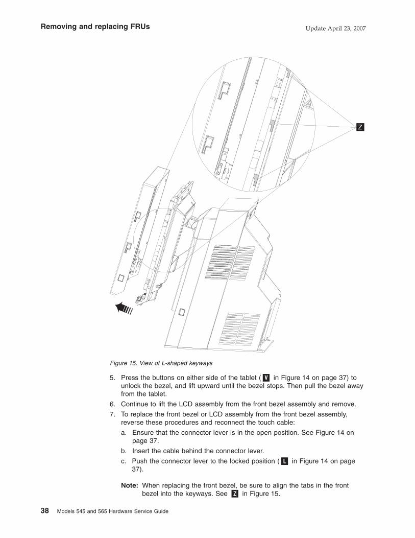
5. Press the buttons on either side of the tablet (�V� in Figure 14 on page 37) to
unlock the bezel, and lift upward until the bezel stops. Then pull the bezel away
from the tablet.
6. Continue to lift the LCD assembly from the front bezel assembly and remove.
7. To replace the front bezel or LCD assembly from the front bezel assembly,
reverse these procedures and reconnect the touch cable:
a. Ensure that the connector lever is in the open position. See Figure 14 on
page 37.
b. Insert the cable behind the connector lever.
c. Push the connector lever to the locked position (�L� in Figure 14 on page
37).
Note: When replacing the front bezel, be sure to align the tabs in the front
bezel into the keyways. See �Z� in Figure 15.
Z
Figure 15. View of L-shaped keyways
Removing and replacing FRUs Update April 23, 2007
38 Models 545 and 565 Hardware Service Guide

Operator card - removing and replacing
This section describes how to remove the operator card.
1. Switch OFF the power to the SurePOS 500. Unplug the power cord from the
external power source.
2. Follow the steps described in “Front bezel and LCD assembly - removing and
replacing” on page 37 to lift off the front bezel.
3. Disconnect the cable from the operator card.
4. See Figure 16. Remove the two screws (�D�) and lift out the card.
5. To replace, reverse these procedures.
D
Figure 16. Removing the operator card
Removing and replacing FRUsUpdate April 23, 2007
Chapter 3. Removing and replacing FRUs for the SurePOS 500 Models 545 and 565 39

Tablet hinge assembly – removing and replacing
1. Switch OFF the power to the SurePOS 500. Unplug the power cord from the
external power source.
2. Remove the tablet as described in “Display tablet - removing and replacing” on
page 35
3. Remove the front cover as described in “Front (or HDD) cover removal” on page
30
4. Remove the top cover. See “Top cover removal” on page 33
5. Lift to remove the tower center cover and the hinge cover (see “Hinge cover
removal” on page 34).
6. Remove the four screws shown in Figure 17 and lift off the hinge assembly.
7. To replace, reverse these procedures.
Figure 17. Removing the tablet hinge assembly
Removing and replacing FRUs Update April 23, 2007
40 Models 545 and 565 Hardware Service Guide

Hard disk drive and bracket – removing and replacing
Attention: The hard disk drive (HDD) is a static-sensitive device. See “Handling
static-sensitive devices” on page 28. User care not to drop or jar the HDD during
assembly. Do not use an impact power driver.
Note: The HDD and bracket are available together as one FRU, and are also
available separately.
1. Switch OFF the power to the SurePOS 500. Unplug the power cord from the
external power source.
2. As shown in Figure 18, tilt back the tablet.
3. Remove the front cover as described at “Front (or HDD) cover removal” on
page 30.
4. Disconnect the two cables from the HDD.
Figure 18. HDD installation. For clarity, this figure shows additional components removed;
however, you do not remove these to remove the HDD.
Removing and replacing FRUsUpdate April 23, 2007
Chapter 3. Removing and replacing FRUs for the SurePOS 500 Models 545 and 565 41

5. See Figure 19. Loosen the captive thumbscrew (�A�) and remove the HDD
assembly by lifting it off of the hooks on the frame (�B�).
6. If the HDD is a separate FRU, place the HDD on a flat surface and remove the
four screws and bracket.
7. Place the old HDD in protective packaging.
8. Attach the bracket to the new HDD with the four screws.
9. Reinstall the HDD and bracket assembly:
a. Reconnect the power and data cables to the HDD.
b. Reinsert the HDD and bracket into the frame hooks and replace the
thumbscrew
10. Replace the HDD cover.
11. Power on the system and use the CMOS Setup Utility to verify that the system
recognizes the new HDD.
Note: If the system fails to recognize the new HDD, verify that all connectors
are properly seated and that the address jumper is correctly installed. If
the HDD requires a jumper to be recognized as Drive 0, the correct
position is indicated on a label on the HDD.
A
B
Figure 19. Removing the hard disk drive and bracket. For clarity, this figure shows additional
components removed; however, you do not remove these to remove the HDD.
Removing and replacing FRUs Update April 23, 2007
42 Models 545 and 565 Hardware Service Guide

Hard disk drive fan and bracket – removing and replacing
1. Switch OFF the power to the SurePOS 500. Unplug the power cord from the
external power source.
2. Remove the rear cover as described in “Rear cover removal” on page 31
3. Remove the top cover (�A� in Figure 20) as described in “Top cover removal” on
page 33.
4. Remove the tower center cover (�B�in Figure 20) by lifting upward.
5. See Figure 20. Unsnap and remove the HDD fan (�C�) and bracket to remove.
6. Disconnect the cable from the fan.
7. To replace, reverse these procedures.
A
B
C
Figure 20. Removing the HDD fan and bracket
Removing and replacing FRUsUpdate April 23, 2007
Chapter 3. Removing and replacing FRUs for the SurePOS 500 Models 545 and 565 43

Hard disk drive cables – removing and replacing
1. Switch OFF the power to the SurePOS 500. Unplug the power cord from the
external power source.
2. Tilt back the tablet.
3. Remove the front cover as described at “Front (or HDD) cover removal” on
page 30.
4. If present, remove the speaker. See “Speaker – removing and replacing” on
page 64.
5. Remove the HDD power connector and data cable connector from the HDD.
6. Cut any cable ties on the cables.
7. Disconnect the power cable and the data cable from the system board.
8. Remove the base plate. See “Base plate – removing and replacing” on page
58.
9. Pull the power cable free from the plastic guide in the frame.
10. To replace, reverse these procedures.
Removing and replacing FRUs Update April 23, 2007
44 Models 545 and 565 Hardware Service Guide

Cable tie bar – removing and replacing
1. Switch OFF the power to the SurePOS 500. Unplug the power cord from the
external power source.
2. Follow the instructions described in “Rear cover removal” on page 31.
3. Loosen the captive thumbscrew �B�, as shown in Figure 21.
4. Remove the latch arm from the hinge by rotating and sliding it from the slots.
5. To replace, reverse these procedures.
B
Figure 21. Removing the cable tie bar
Removing and replacing FRUsUpdate April 23, 2007
Chapter 3. Removing and replacing FRUs for the SurePOS 500 Models 545 and 565 45

Power supply – removing and replacing
1. Switch OFF the power to the SurePOS 500. Unplug the power cord from the
external power source.
2. Remove the back cover as described at “Rear cover removal” on page 31.
3. Unplug the AC power cord on the back of the power supply.
4. Unlatch the power supply latch arm by loosening the captive thumbscrew and
swinging the arm upward.
5. Lift upward until it stops.
6. Pull the power supply out.
7. To replace, make sure the latch arm is all the way up. Slide the power supply
into the bottom of the system unit until it stops. Ensure that the power supply
latch arm hooks go inside the metal frame.
8. Rotate the latch arm downward and replace the thumbscrew.
Note: You may need to push in at the left bottom of the power supply to get the
thumbscrew to align with the screw hole.
Figure 22. Removing the power supply
Removing and replacing FRUs Update April 23, 2007
46 Models 545 and 565 Hardware Service Guide

Power supply latch arm – removing and replacing
1. Switch OFF the power to the SurePOS 500. Unplug the power cord from the
external power source.
2. Follow the instructions described in “Rear cover removal” on page 31.
3. Follow the instructions described in “Power supply – removing and replacing” on
page 46
4. Remove screws (�H�) and then lift off the power supply.
5. To replace, reverse these procedures.
H
Figure 23. Removing the power supply latch arm
Removing and replacing FRUsUpdate April 23, 2007
Chapter 3. Removing and replacing FRUs for the SurePOS 500 Models 545 and 565 47

Rear connector panel (tailgate) – removing and replacing
1. Switch OFF the power to the SurePOS 500. Unplug the power cord from the
external power source.
2. Remove the rear cover as described at “Rear cover removal” on page 31.
3. Disconnect all I/O cables from the tailgate:
v Speaker
v Video
v Serial ATA
v Power
4. Remove the power supply. See “Power supply – removing and replacing” on
page 46.
5. Unlatch the I/O tailgate cover by sliding the latches (�A� in Figure 24) toward the
center.
6. Open the I/O tailgate cover by rotating it downward.
A
Figure 24. Opening the I/O tailgate cover
Removing and replacing FRUs Update April 23, 2007
48 Models 545 and 565 Hardware Service Guide

7. As shown in Figure 25, pull the I/O tailgate and attached I/O tailgate cover from
the system board.
8. To replace, reverse these procedures, being sure to align the metal tabs on the
side of the tailgate with the plastic guides on the frame.
Figure 25. Removing the tailgate
Removing and replacing FRUsUpdate April 23, 2007
Chapter 3. Removing and replacing FRUs for the SurePOS 500 Models 545 and 565 49

System board – removing and replacing
Attention: Establish personal grounding before touching this unit. See
“Electrostatic Discharge (ESD)” on page 136.
Note: The system board assembly comes with a tray and top cover.
1. Switch OFF the power to the SurePOS 500. Unplug the power cord from the
external power source.
2. Follow the steps described in “Rear cover removal” on page 31.
3. Remove the power supply as described in “Power supply – removing and
replacing” on page 46
4. Disconnect the cables and remove the I/O tailgate cover as described in “Rear
connector panel (tailgate) – removing and replacing” on page 48
5. Grasp the entire assembly and slide it out toward the top as shown in Figure 26.
Figure 26. Removing the system board
Removing and replacing FRUs Update April 23, 2007
50 Models 545 and 565 Hardware Service Guide

Transfer modules to the new system board
Place the assembly on a table and remove the following parts:
v Memory modules – See “Memory modules – removing and replacing” on
page 56.
v Heatsink and fan - See “Processor fan/heatsink assembly - removing and
replacing” on page 54.
v Processor – See “Processor module – removing and replacing” on page
55.
v Video adapter, if installed. See “Video adapter card– removing and
replacing” on page 63.
v Optional integrated VFD
Install these parts on the new system board. The new system board comes
with all required jumpers and with a new battery.
Update system software
1. Ensure system BIOS is equal to or greater than that from the old
system board. See “Updating the flash BIOS” on page 17.
2. Reprogram the Vital Product Data (VPD).
a. Boot using the memory key.
b. Choose POS System Test.
c. Choose Utilities.
d. Choose Vital Product Data Utility.
e. Choose Update VPD.
f. Choose the model and press Enter.
g. Choose Update VPD again.
h. Enter the machine serial number and press Enter.
i. Exit.
Removing and replacing FRUsUpdate April 23, 2007
Chapter 3. Removing and replacing FRUs for the SurePOS 500 Models 545 and 565 51

System-board jumper location and settings
Figure 27 shows the system-board jumper locations. See the following topics for
jumper descriptions and information about jumper settings.
Table 14 describes the system board jumper setting. All jumper pins have the pin
number printed on the system board for easy identification.
Table 14. System board jumper settings
Jumper Default pin
location:
Description
J25 pins 1 and 2 CMOS Memory clear: To clear the CMOS, momentarily
place the jumper on pins 2 and 3
System-board battery – removing and replacing
1. Switch OFF the power to the SurePOS 500. Unplug the power cord from the
external power source.
2. Remove the rear cover as described at “Rear cover removal” on page 31.
3. Remove the power supply. See “Power supply – removing and replacing” on
page 46
4. Remove the I/O tailgate as described in “Rear connector panel (tailgate) –
removing and replacing” on page 48
A
Figure 27. System board jumper location
Removing and replacing FRUs Update April 23, 2007
52 Models 545 and 565 Hardware Service Guide

5. Remove the old battery from the slot �L� as shown in Figure 28.
6. Facing the rear of the machine, insert the new battery with the positive side to
the left
L
Figure 28. System-board battery
Removing and replacing FRUsUpdate April 23, 2007
Chapter 3. Removing and replacing FRUs for the SurePOS 500 Models 545 and 565 53

Processor fan/heatsink assembly - removing and replacing
1. Switch OFF the power to the SurePOS 500. Unplug the power cord from the
external power source.
2. Remove the rear cover as described at “Rear cover removal” on page 31.
3. Remove the power supply. See “Power supply – removing and replacing” on
page 46
4. Remove the I/O tailgate cover as described in “Rear connector panel (tailgate) –
removing and replacing” on page 48
5. Unplug the processor fan cable.
6. Press the latch (�A�in Figure 29) on the processor fan bracket and rotate fan
bracket away from the duct.
7. Remove the processor fan/heatsink by loosening the four screws.
8. See “Processor module – removing and replacing” on page 55 to remove the
processor.
9. Reverse these procedures to replace.
Note: If you are reusing the existing heatsink, make sure that the thermal material
is not torn or damaged. Replace, if needed. The thermal material comes
installed on a new heatsink or with a new processor.
A
Figure 29. Removing the processor fan/ heatsink assembly. The placement of the unit in the
top view is for illustrative purposes only.
Removing and replacing FRUs Update April 23, 2007
54 Models 545 and 565 Hardware Service Guide
Processor module – removing and replacing
Note: The processor and fan sink come as one FRU. Do not use the old fan sink
when replacing the processor.
Attention: Establish personal grounding before touching this unit. See “Electrostatic
Discharge (ESD)” on page 136.
The LGA 775 CPU socket contains very finely pitched pins. You must take care
when servicing the CPU as any damage to the socket results in a non-functional
system board. Be sure to use the section cup tool provided with the FRU
1. Switch OFF the power to the SurePOS 500. Unplug the power cord from the
external power source.
2. Remove the rear cover as described at “Rear cover removal” on page 31.
3. Remove the power supply as described in “Power supply – removing and
replacing” on page 46.
4. Remove the tailgate as described in “Rear connector panel (tailgate) – removing
and replacing” on page 48.
Attention: The SurePOS Models 545 and 565 contain a LGA 775 CPU socket.
This socket contains very finely pitched pins. You must take care when servicing the
CPU as any damage to the socket results in a non-functional system board. Be
sure to use the section cup tool provided with the FRU processor.
5. Remove the processor fan/heatsink assembly as described in “Processor
fan/heatsink assembly - removing and replacing” on page 54.
Note: Examine the thermal interface on the new heatsink. If the thermal
interface is damaged, replace the heatsink.
6. Release the latch and carefully remove the processor from the system board.
7. To replace, reverse these procedures.
Removing and replacing FRUsUpdate April 23, 2007
Chapter 3. Removing and replacing FRUs for the SurePOS 500 Models 545 and 565 55

Memory modules – removing and replacing
Attention: Establish personal grounding before touching this unit. For more
information, see “Electrostatic Discharge (ESD)” on page 136.
All system boards have 2 memory sockets. See Figure 30. The factory-installed
base memory occupies one of the sockets. If you order is greater than the base
memory, you may or may not have an empty socket.
1. Switch OFF the power to the SurePOS 500. Unplug the power cord from the
external power source.
2. Remove the back cover. See “Rear cover removal” on page 31.
3. As shown in Figure 24 on page 48, lower the I/O tailgate cover.
4. Locate the memory modules. See �A� in Figure 30.
A
Figure 30. Memory socket location
Removing and replacing FRUs Update April 23, 2007
56 Models 545 and 565 Hardware Service Guide

5. Press the latches away from the module as shown in Figure 31.
6. Touching only the top corners of the module, pull it gently until it is free from
the socket.
7. Before inserting a replacement module, note the alignment notch along the
bottom of the module and where the module plugs into the slot.
8. Carefully align the module in the slot and then press it into the slot until it is
secured by the clip.
Note: Ensure the memory module is fully seated in the socket and the retainer
tabs are fully upright and engaged in the memory module side notches.
9. Replace the I/O tailgate cover.
10. Replace the rear cover.
Memory modules and industry standards
You should only use memory provided by IBM Retail for use in Models 545 and
565. Although advertised as industry standard, all memory does not work with every
product, IBM performs extensive life and reliability testing to insure that memory
offered by IBM will operate correctly over all voltage and temperature ranges.
Retainer
Figure 31. Memory module removal
Removing and replacing FRUsUpdate April 23, 2007
Chapter 3. Removing and replacing FRUs for the SurePOS 500 Models 545 and 565 57

Base plate – removing and replacing
1. Switch OFF the power to the SurePOS 500. Unplug the power cord from the
external power source.
2. Remove the rear cover as described in “Rear cover removal” on page 31.
3. Open the cable tie bar and disconnect all of the cables.
4. Remove the two screws �S� attaching the base plate to the frame.
5. Slide the tower toward the rear and lift it off the base.
S
Figure 32. Removing the base plate
Removing and replacing FRUs Update April 23, 2007
58 Models 545 and 565 Hardware Service Guide

Optional features
This section describes how to remove and replace the optional features.
Magnetic stripe reader (MSR) – removing and replacing
1. Switch OFF the power to the SurePOS 500. Unplug the power cord from the
external power source.
2. Unplug the MSR cable �A�, as shown in Figure 33 and remove the cable from
the cable groove �B�.
3. Remove the thumbscrew �C� that secures the MSR.
4. Slide the MSR�D� up and off.
To replace the MSR, reverse this procedure.
Note: If you are replacing a dual-sided, single-track MSR, you must set the switch
under the MSR cover next to the slot to either the RS-232 or keyboard
position, depending on the configuration of the MSR removed.
After installation, run the diagnostics to ensure that the MSR operates correctly. See
“Using the IBM Diagnostics for POS Systems and Peripherals package” on page
16.
A
D
B
C
Figure 33. Removing the MSR
Removing and replacing FRUsUpdate April 23, 2007
Chapter 3. Removing and replacing FRUs for the SurePOS 500 Models 545 and 565 59

MSR hole plug – removing and replacing
1. Use a screwdriver to pry off the MSR hole plug.
2. To replace, align plug with hole and press.
A
D
B
C
PC card blank – removing
1. Switch OFF the power to the SurePOS 500. Unplug the power cord from the
external power source.
2. Remove the HDD cover. See “Front (or HDD) cover removal” on page 30.
3. Remove the door in the direction shown in Figure 34 on page 61.
Removing and replacing FRUs Update April 23, 2007
60 Models 545 and 565 Hardware Service Guide

PC card – removing and replacing
1. Switch OFF the power to the SurePOS 500. Unplug the power cord from the
external power source.
2. Remove the front cover. See “Front (or HDD) cover removal” on page 30.
3. Remove the PC card cover as shown in Figure 34.
4. If a wireless LAN antenna cover is present, remove the two screws, as shown in
Figure 35 on page 62.
5. Press the PC card adapter eject button. Do not pull the interface cable to
remove the adapter card and connector. Gently pull on the adapter card.
Figure 34. Removing the PC card adapter slot blank
Removing and replacing FRUsUpdate April 23, 2007
Chapter 3. Removing and replacing FRUs for the SurePOS 500 Models 545 and 565 61
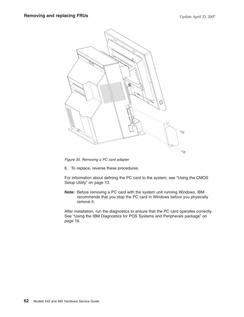
6. To replace, reverse these procedures.
For information about defining the PC card to the system, see “Using the CMOS
Setup Utility” on page 13.
Note: Before removing a PC card with the system unit running Windows, IBM
recommends that you stop the PC card in Windows before you physically
remove it.
After installation, run the diagnostics to ensure that the PC card operates correctly.
See “Using the IBM Diagnostics for POS Systems and Peripherals package” on
page 16.
Figure 35. Removing a PC card adapter
Removing and replacing FRUs Update April 23, 2007
62 Models 545 and 565 Hardware Service Guide

Video adapter card– removing and replacing
Attention: The dual-video adapter is a static-sensitive device. See “Handling
static-sensitive devices” on page 28.
1. Switch OFF the power to the SurePOS 500. Unplug the power cord from the
external power source.
2. Remove the back cover as described at “Rear cover removal” on page 31.
3. Remove the power supply. See “Power supply – removing and replacing” on
page 46
4. Remove the three screws shown in Figure 36 and remove the video adapter
card.
5. To replace, reverse these procedures.
After installation, run the diagnostics to ensure that the video adapter card operates
correctly. See “Using the IBM Diagnostics for POS Systems and Peripherals
package” on page 16.
Figure 36. Video adapter card removal
Removing and replacing FRUsUpdate April 23, 2007
Chapter 3. Removing and replacing FRUs for the SurePOS 500 Models 545 and 565 63
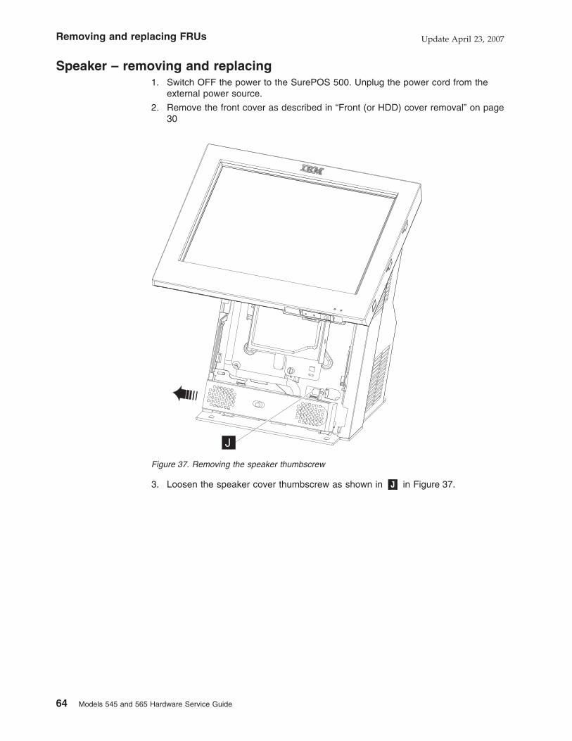
Speaker – removing and replacing
1. Switch OFF the power to the SurePOS 500. Unplug the power cord from the
external power source.
2. Remove the front cover as described in “Front (or HDD) cover removal” on page
30
3. Loosen the speaker cover thumbscrew as shown in �J� in Figure 37.
J
Figure 37. Removing the speaker thumbscrew
Removing and replacing FRUs Update April 23, 2007
64 Models 545 and 565 Hardware Service Guide

4. Slide the speaker shield to the left and lift it off of the hooks (�H�in Figure 38) to
remove.
5. Disconnect the speaker cable from the speaker extension cable.
6. To replace, reverse these procedures.
Note: The speaker hooks must fit into the hooks on the frame, or the HDD cover
will not close properly.
H
Figure 38. Removing the speaker and speaker EMC shield
Removing and replacing FRUsUpdate April 23, 2007
Chapter 3. Removing and replacing FRUs for the SurePOS 500 Models 545 and 565 65

Integrated customer display – removing and replacing
1. Switch OFF the power to the SurePOS 500. Unplug the power cord from the
external power source.
2. Remove the rear cover. See “Rear cover removal” on page 31.
3. Open the I/O tailgate cover by opening the latches and lowering the cover.
Note: You do not need to remove the tailgate cover.
4. Disconnect the integrated display cable from the rear of the system board.
5. Remove the existing integrated display or top cover. See “Top cover removal”
on page 33.
6. Snap the new integrated display in place, after routing the cable through the
hole (�A� in Figure 39 in the top of the unit.
7. Connect the cable to the rear upper-right corner (�B�) of the system board.
8. Close the I/O tailgate cover and replace the rear cover.
9. To replace, reverse these procedures.
After installation, run the diagnostics to ensure that the integrated display operates
correctly. See “Using the IBM Diagnostics for POS Systems and Peripherals
package” on page 16.
A
B
Figure 39. Removing the integrated display
Removing and replacing FRUs Update April 23, 2007
66 Models 545 and 565 Hardware Service Guide

Modular flash drive – removing and replacing
Attention: The modular flash drive is a static-sensitive device. See “Handling
static-sensitive devices” on page 28.
1. Switch OFF the power to the SurePOS 500. Unplug the power cord from the
external power source.
2. Remove the rear cover as described in “Rear cover removal” on page 31.
3. Unplug the AC power cord on the back of the power supply.
4. Remove the power supply. See “Power supply – removing and replacing” on
page 46.
5. Remove tablet cable connector end from the system board by loosening the
two thumbscrews as shown in “Display tablet cable – removing and replacing”
on page 36.
6. The modular flash drive �A� is installed on the system board on the lower left
side of the panel.
7. When removing the flash drive, squeeze the tip of the white plastic stand off to
release the flash drive.
8. Grasp firmly and pull directly back to avoid damaging pins.
9. To replace, reverse these procedures.
10. When installing, make sure to line up the flash drive hole with the standoff and
push in to fully seat the connector.
A
Figure 40. Modular flash drive
Removing and replacing FRUsUpdate April 23, 2007
Chapter 3. Removing and replacing FRUs for the SurePOS 500 Models 545 and 565 67
|
|||
|
||
||
|
|
||
|||
|||
||
|
|
||

Removing and replacing FRUs Update April 23, 2007
68 Models 545 and 565 Hardware Service Guide

Chapter 4. Mounting the SurePOS 500 Models 545 and 565
Mounting the base plate on a countertop . . . . . . . . . . . . . . . 71
Non-keyboard-integration tray mounting . . . . . . . . . . . . . . . . 74
Countertop with non-keyboard-integration tray mounting . . . . . . . . . 74
Installing filler panels without a printer . . . . . . . . . . . . . . 79
Cash drawer . . . . . . . . . . . . . . . . . . . . . . . . . 79
Keyboard-integration tray . . . . . . . . . . . . . . . . . . . . . 84
Countertop and full-size cash drawer . . . . . . . . . . . . . . . . 84
Mounting the integration tray to a countertop . . . . . . . . . . . . 84
Installing additional peripheral devices . . . . . . . . . . . . . . . . 93
Mounting a distributed customer display and APA display to a cash drawer 93
Installing IBM 4610 SureMark Models TF6 or TF7 printers . . . . . . . . 95
Table 15 describes the various mounting configurations of the SurePOS 500.
Note
Figures in this section are representative of the SurePOS 500 family and may
have slight differences with the Models 545 and 565. All mounting procedures
are accurate.
Table 15. Mounting configurations
To mount using the base to the
countertop, see “Mounting the
base plate on a countertop” on
page 71.
Update April 23, 2007
© Copyright IBM Corp. 2006, 2007 69

Table 15. Mounting configurations (continued)
To mount to a countertop using
the non-keyboard-integration tray,
see “Countertop with
non-keyboard-integration tray
mounting” on page 74.
To mount on a cash drawer using
the non-keyboard-integration tray,
see “Cash drawer” on page 79.
Mounting the Models 545 and 565 Update April 23, 2007
70 Models 545 and 565 Hardware Service Guide
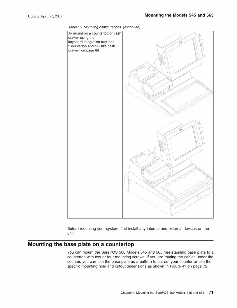
Table 15. Mounting configurations (continued)
To mount on a countertop or cash
drawer using the
keyboard-integration tray, see
“Countertop and full-size cash
drawer” on page 84
Before mounting your system, first install any internal and external devices on the
unit.
Mounting the base plate on a countertop
You can mount the SurePOS 500 Models 545 and 565 free-standing base plate to a
countertop with two or four mounting screws. If you are routing the cables under the
counter, you can use the base plate as a pattern to cut out your counter or use the
specific mounting hole and cutout dimensions as shown in Figure 41 on page 72.
Mounting the Models 545 and 565Update April 23, 2007
Chapter 4. Mounting the SurePOS 500 Models 545 and 565 71

Route all cables (including the AC power cord) through the cable-access hole in the
base plate. If you are routing the cables on top of the counter, route all cables out
the rear of the system. Lay the cables flat along the countertop.
To mount the system directly on a countertop:
Note: Before you begin, acquire two mounting screws. These are not supplied.
1. Remove the rear cover.
2. Remove the cable-tie bar by loosening the thumbscrew.
3. Use the SurePOS 500 base plate as a pattern for drilling two mounting-screw
holes at location �S� in Figure 42 on page 73. If you plan to route the cables
underneath the counter, use the base plate as a pattern to drill the cable
opening and for drilling the holes for the mounting screws.
4. Attach the system to the countertop with two mounting screws.
133
173.7
(2x)
07.
2
18
19.15
35
13.85
25
(2x)
8.8
mm
(2x)
211
.7
(2x)
3
18166(2x) 07.2
Figure 41. Base plate countertop dimensions
Mounting the Models 545 and 565 Update April 23, 2007
72 Models 545 and 565 Hardware Service Guide

5. Connect the power cable to the power supply.
6. Connect the peripheral device cables to the appropriate ports on the rear
connector panel. Make the connections on the bottom row of the connector
panel first and work upward. Ensure that the cables are routed to the right of
the power cord.
Note: For a diagram of the port layout, see “Connectors, power, and
brightness controls” on page 5.
7. Rotate the cable-tie bar back into place and tighten the thumbscrew.
8. Use tie-wraps to secure cables to the cable-tie bar, if desired.
9. Replace the rear cover.
10. Plug the AC power cord into an AC outlet.
11. After your installation is complete, switch ON the power to the SurePOS 500
and verify that the system is operating correctly by checking the indicator lights
(LEDs) on the front of the touch screen.
12. Install your software. Refer to IBM SurePOS Model 545 and 565 Operating
System Installation Guide.
S
Figure 42. Attaching the base foot to the countertop
Mounting the Models 545 and 565Update April 23, 2007
Chapter 4. Mounting the SurePOS 500 Models 545 and 565 73

Non-keyboard-integration tray mounting
Some integration trays for countertop are designed to accommodate a keyboard
and cash drawers, and some are not. The procedures in this section are for
non-keyboard-integration tray mounting for the countertop and cash drawer. For
keyboard-integration tray mounting, go to “Countertop and full-size cash drawer” on
page 84.
Countertop with non-keyboard-integration tray mounting
The countertop integration tray can be used as a free-standing unit or secured to a
countertop using mounting screws. Use the countertop integration tray drawing that
comes with it as a pattern for drilling the four mounting holes and for the cable
opening, if you plan to route the cables through the countertop. Four screws (not
provided) are required to mount the integration tray to a countertop. For specific
mounting hole and cutout dimensions, see Figure 44 on page 75.
Figure 43. Countertop with non-keyboard-integration tray mounting
Mounting the Models 545 and 565 Update April 23, 2007
74 Models 545 and 565 Hardware Service Guide

Note: Acquire the four mounting screws before you begin this installation.
1. For a free-standing unit, ensure that the four rubber feet �H� are installed on
the bottom of the countertop integration tray (as shown in Figure 47 on page
77).
2. To secure the countertop integration tray to a countertop, perform the following
steps:
a. Detach the plastic fence from the countertop integration tray. To detach the
plastic fence:
1) Spread the rear sides away from the tray as shown in Figure 45.
2) Alternating from side to side, slide the plastic fence �B� about 7 mm
(0.25 in.) until the plastic fence is detached from the metal integration
tray �A�, as shown in Figure 46 on page 76.
441.52 mm (17.38 in.)
343.02 mm (13.51 in.)
64.1 mm (2.52 in.)
90 mm(3.54 in.)
7 mm(0.28 in.)
66.22 mm(2.6 in.)
40.72 mm(1.6 in.)
149 mm(5.87 in.)
128 mm(5.04 in.)
95 mm(3.7 in.)
260.16 mm(10.24 in.)
66.22 mm(2.6 in.)
45.76 mm(1.8 in.)
340 mm(13.39 in.)
Figure 44. Countertop integration tray pattern with display and countertop cutout on right side
Figure 45. Detaching the fence from the tray
Mounting the Models 545 and 565Update April 23, 2007
Chapter 4. Mounting the SurePOS 500 Models 545 and 565 75
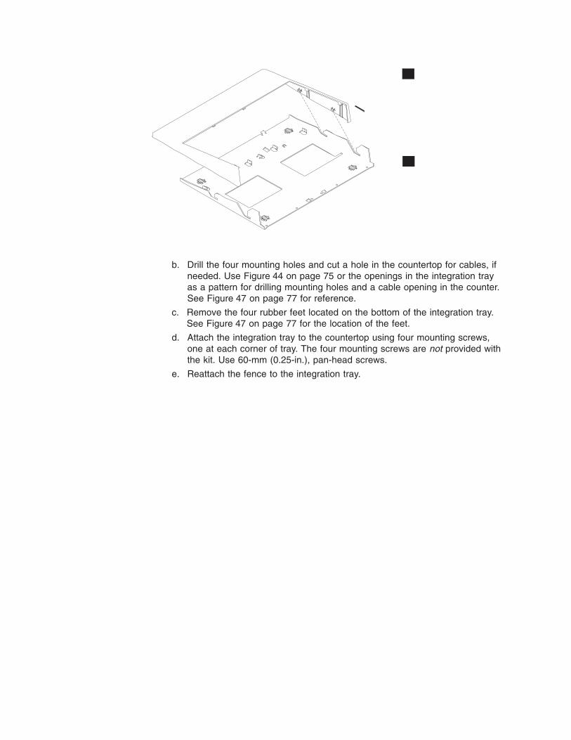
b. Drill the four mounting holes and cut a hole in the countertop for cables, if
needed. Use Figure 44 on page 75 or the openings in the integration tray
as a pattern for drilling mounting holes and a cable opening in the counter.
See Figure 47 on page 77 for reference.
c. Remove the four rubber feet located on the bottom of the integration tray.
See Figure 47 on page 77 for the location of the feet.
d. Attach the integration tray to the countertop using four mounting screws,
one at each corner of tray. The four mounting screws are not provided with
the kit. Use 60-mm (0.25-in.), pan-head screws.
e. Reattach the fence to the integration tray.
B
A
Figure 46. Sliding the fence off of the integration tray
Mounting the Models 545 and 565 Update April 23, 2007
76 Models 545 and 565 Hardware Service Guide

Table 16. Countertop integration tray legend
�A� Fence �G� System filler panel
�B� SurePOS 500 �H� Four rubber feet
�C� Mounting plate �I� Countertop integration tray
�D� 4610 SureMark Printer �J� Small filler panel
�E� Mounting plate for 4610 SureMark
printer
�K� Filler panel used when printer is
absent
�F� Center filler panel �L� Filler panel used when printer is
present
3. Remove the rear cover as shown in “Rear cover removal” on page 31.
4. Attach small filler panel �J� to the mounting plate �C�.
5. Remove the base plate and place the unit on the mounting plate �C�.
B
C
J
K
K
D
I
E
G
H
A
F
L
Figure 47. Overview of integration tray, SurePOS 500, printer, and filler panels
Mounting the Models 545 and 565Update April 23, 2007
Chapter 4. Mounting the SurePOS 500 Models 545 and 565 77

6. Attach the SurePOS 500 and its mounting plate �C� to the right side of the
integration tray �I� as shown in Figure 47 on page 77. Slide the front of the
mounting plate under the appropriate pair of tabs on the tray and secure the
rear of the mounting plate to the tray with two thumbscrews.
7. Install the IBM 4610 SureMark Printer on the integration tray. Go to “Installing
IBM 4610 SureMark Models TF6 or TF7 printers” on page 95 for detailed
instructions on mounting plate installation and printer cable routing.
a. Attach the printer to its mounting plate as shown in Figure 66 on page 97.
b. Install the printer and the printer cables and route the cables as shown in
Figure 65 on page 97.
8. Connect the peripheral device cables to the appropriate ports on the rear
connector panel. Make the connections on the bottom row of the connector
panel first and work upward. Ensure that the cables are routed to the right of
the power cord.
Note: For a diagram of the port layout, see “Connectors, power, and
brightness controls” on page 5.
9. Use tie-wraps to secure cables to the cable-tie bar, if desired.
10. Replace the rear cover.
11. Plug the AC power cord into an AC outlet.
12. Replace the SurePOS 500 rear cover.
13. Install the filler panels after you route all the cables to your system.
a. Install the outer ends of the filler panels �L� and �G� into the integration
tray. Notice that the printer filler panel, shown on the right, is narrower than
the system filler panel. Also, the system filler panel has a bottom slot that
allows you to route the cables out the back.
b. Use the narrow filler panel �K� to lock the filler panels together between
the system and the printer.
Note: Depending on your desired configuration, you could have unused filler
panels.
14. Plug the system and printer AC power cords into an AC outlet.
15. After your installation is complete, press the printer power switch under the
printer cover to power On the printer.
L
K
G
Figure 48. Connecting filler panels
Mounting the Models 545 and 565 Update April 23, 2007
78 Models 545 and 565 Hardware Service Guide

16. Switch ON the power to the SurePOS 500. Verify that the system is operating
correctly by checking the indicator lights (LEDs) on the front of the touch
screen.
17. Install your software. Refer to IBM SurePOS Model 545 and 565 Operating
System Installation Guide.
Installing filler panels without a printer
For systems without a printer:
1. Install the mounting plate in the center of the base using the removable
thumbscrews. See Figure 47 on page 77.
2. Install the system unit in the center using the mounting plate. Use system filler
�G� and �K�.
Cash drawer
You can mount the SurePOS 500 on a full-size cash drawer by first installing an
integration tray on the cash drawer. Follow these steps:
1. To mount the integration tray onto the cash drawer:
a. Tilt the integration tray forward, and slide the tabs into the slots near the
front of the drawer. Lay the tray down on the cash drawer.
b. Attach the cash drawer integration tray to the cash drawer by tightening
two M6x8 screws �A� at the rear of tray, as shown in Figure 49.
A
Figure 49. Attaching the integration tray to cash drawer
Mounting the Models 545 and 565Update April 23, 2007
Chapter 4. Mounting the SurePOS 500 Models 545 and 565 79

2. To install the SurePOS 500 on an integration tray:
a. Remove the rear cover. “Rear cover removal” on page 31.
b. Remove the base plate. See “Base plate – removing and replacing” on
page 58.
c. Attach the system base to the mounting plate �B� with the screws �C�, as
shown in Figure 50.
d. Open the rear cash drawer cover �D� by pushing in the two buttons located
on each side of the cash drawer. This provides access to the cash drawer
connector for cabling it to the system. You will also route cables inside the
cover through hole �E� and to the system.
3. For installations without a printer, install the mounting plate in the center of
the base using the removable thumbscrews. Place the filler panels on both
sides. See Figure 47 on page 77. Install rear system panel �G� first and use
filler panels �K� to lock in filler panel �G� onto the tray.
4. Install the IBM 4610 SureMark printer on the integration tray with the SurePOS
500. Go to “Installing IBM 4610 SureMark Models TF6 or TF7 printers” on
page 95 for detailed instructions on printer cable routing, RS-232 printer switch
settings, and mounting plate installation:
Figure 50. Attaching a mounting plate to center of cash-drawer integration tray
Mounting the Models 545 and 565 Update April 23, 2007
80 Models 545 and 565 Hardware Service Guide

a. Plug the data and power cables into the printer, routing the data cable,
under the cable tie bar and toward the rear connector panel as shown in
Figure 65 on page 97.
b. Attach the SurePOS 500 Models 545 and 565 base mounting plate �A� to
the right side of the integration tray. Slide the front of the plate under the
appropriate pair of tabs on the integration tray. Secure the rear of the plate
to the tray with two thumbscrews as shown in Figure 51.
c. Attach the printer �B� to the printer base mounting plate by sliding it onto
the two tabs until it locks in place.
d. Attach the printer base mounting plate �C� to the integration tray. Slide the
front of the plate under the appropriate pair of tabs on the integration tray.
Secure the rear of the plate to the tray with two thumbscrews.
5. Plug the cash-drawer cable into the cash drawer and route it under the
cable-tie bar to the rear connector panel.
6. Plug the data and power cables into the printer, routing the data cable under
the cable tie-bar and toward the rear connector panel.
Figure 51. Attaching mounting plate to the cash drawer integration tray
Mounting the Models 545 and 565Update April 23, 2007
Chapter 4. Mounting the SurePOS 500 Models 545 and 565 81

7. Route all cables through the hole at the center rear of the cash drawer. Then
route the cables through the rear of the system, laying them flat on top of the
cash-drawer integration tray.
8. If you are installing a distributed-character display or an all points addressable
(APA) display, see “Mounting a distributed customer display and APA display to
a cash drawer” on page 93.
9. Connect the peripheral cables to the appropriate ports on the rear connector
panel. See “Connectors, power, and brightness controls” on page 5.
Note: If you are installing a distributed-character display, route the cable
through the unattached rear modesty panel �C� in Figure 52 on page
83.
10. Use tie-wraps to secure cables to the cable-tie bar. Be sure to run cables to
the right of the power cable when viewed from the rear.
11. Replace the rear cover.
12. See Figure 52 on page 83. Install the filler panels after you route all the cables
to your system. Note that filler panel �A� locks filler panels �B� onto the tray.
Install the filler panels after you have routed all of the cables.
a. Install the outer ends of the filler panels �B� into the integration tray. Notice
that the printer filler panel, shown on the right, is narrower than the system
filler panel. Also, the system filler panel has a bottom slot that allows you to
route the cables out the back.
b. Use the narrow filler panel �A� to lock the filler panels together between
the system and the printer.
Note: Depending upon your desired configuration, you could have unused
filler panels.
13. Tilt the modesty cover �C� so the front hooks attach to the tray; then push
down until the cover snaps into place.
Mounting the Models 545 and 565 Update April 23, 2007
82 Models 545 and 565 Hardware Service Guide

14. Attach the distributed customer display �D� to the cash drawer with two
thumbscrews �F� and snap the entire unit into place at the rear of the tray.
15. Close the cash-drawer rear cover.
16. Plug the AC power cords for the printer and the system into an AC outlet.
17. After your installation is complete, press the printer power switch under the
printer cover to power on the printer.
18. Switch ON the power to the SurePOS 500. Verify that the system is operating
correctly by checking the indicator lights (LEDs) on the front of the system.
19. Install your software. Refer to IBM SurePOS Model 545 and 565 Operating
System Installation Guide.
Figure 52. Attaching filler panels and the rear modesty cover
Mounting the Models 545 and 565Update April 23, 2007
Chapter 4. Mounting the SurePOS 500 Models 545 and 565 83

Keyboard-integration tray
This section describes how to install a keyboard tray with the SurePOS 500 Models
545 and 565.
Countertop and full-size cash drawer
The full-size keyboard-integration tray can be used as a free-standing unit, secured
to a countertop using mounting screws or mounted to a cash drawer. The SurePOS
500 is mounted with the 4610 SureMark printer using the full-size
keyboard-integration tray.
Important
Devices such as the printer, integrated character display, and keyboard are
mounted the same way when the full-size keyboard-integration tray is used for
a countertop or cash drawer mount. Therefore, the instructions for the
countertop and cash drawer mount have been combined.
Mounting the integration tray to a countertop
Use the countertop keyboard-integration tray as a pattern for drilling the four
mounting holes and for the cable opening, if you plan to route the cables through
the countertop.
Note: Four screws (not provided) are required to mount the integration tray to a
countertop.
1. Prepare the SurePOS 500 to mount to the keyboard-integration tray:
a. Remove the rear cover.
Figure 53. Full-size keyboard-integration tray on a countertop
Mounting the Models 545 and 565 Update April 23, 2007
84 Models 545 and 565 Hardware Service Guide

Notes:
1) If you are routing cables underneath the counter, route them through
the cable-access hole in the counter.
2) If you are routing cables on top of the counter, route them out the back
of the system. Lay them flat along the countertop.
2. For a free-standing unit, ensure that the four rubber feet �A� are installed on
the bottom of the countertop keyboard integration tray (as shown in Figure 54
on page 86).
3. To secure the full-size keyboard-integration tray to a countertop, perform
the following steps:
a. Remove the fence �E� from the countertop keyboard-integration tray by
removing the screws as shown in Figure 54 on page 86.
b. Drill the four mounting holes and cut a hole in the countertop for cables if
needed. Use the openings in the integration tray as a pattern for drilling
mounting holes and a cable opening in the counter.
c. Remove the rubber feet �A� located on the bottom of the integration tray.
See Figure 54 on page 86 for location of feet.
d. Attach the keyboard-integration tray to the countertop using four mounting
screws, one at each corner of tray. The four mounting screws are not
provided with the kit. Use 60-mm (0.25-in.) pan-head screws.
e. Reattach the fence �E� to the tray with the six small screws.
Mounting the Models 545 and 565Update April 23, 2007
Chapter 4. Mounting the SurePOS 500 Models 545 and 565 85

Table 17. Countertop integration tray legend
�A� Four rubber feet �D� Mounting plate
�B� Keyboard-integration tray �E� Fence
�C� Insulator plate
4. Prepare the SurePOS 500 to mount to the keyboard-integration tray:
a. Remove the rear cover.
Notes:
1) If you are routing cables underneath the counter, route them through
the cable-access hole in the counter.
2) If you are routing cables on top of the counter, route them out the back
of the system. Lay them flat along the countertop.
A
C
D
E
B
Figure 54. Countertop keyboard-integration tray assembly
Mounting the Models 545 and 565 Update April 23, 2007
86 Models 545 and 565 Hardware Service Guide

5. Remove the rear cover on the cash drawer. While pressing in on the two
buttons located on the sides of the cash drawer, pull back on the rear cover
back to remove it. Discard this rear cover. A new rear cover is used for
installation of the keyboard integration kit.
6. Install the keyboard-integration tray on a cash drawer:
a. Tilt the integration tray down so the three tabs �B� align with the three tab
holes �C� on the cash drawer as shown in Figure 55. Set the integration
tray down on the cash drawer while aligning the screw holes �D� with holes
on the cash drawer.
b. Secure the integration tray to the cash drawer with two screws at location
�D�.
7. Attach the mounting plate �F� to the integration tray with four plastic washers
and screws as shown in Figure 55.
8. Attach the fence �G� to the integration tray with six small screws.
9. Remove the base plate. See “Base plate – removing and replacing” on page
58.
10. Attach the SurePOS 500 to the mounting plate as shown in Figure 56 on page
88. Slide the unit from the back toward the front until the frame fits into the
A
B
C
DE
F
G
Figure 55. Installing the keyboard-integration tray on a cash drawer
Mounting the Models 545 and 565Update April 23, 2007
Chapter 4. Mounting the SurePOS 500 Models 545 and 565 87

tabs �B�, and the screws �A� and mounting holes �C� are lined up. Tighten the
two base-bracket screws.
11. Install the IBM 4610 SureMark printer on the integration tray, by performing the
following steps:
Note: See the 4610 SureMark Point-of-Sale Printers User’s Guide for detailed
information about switch settings and cabling for the printer.
A
C
B
Figure 56. Installing the SurePOS 500 onto the integration tray
Mounting the Models 545 and 565 Update April 23, 2007
88 Models 545 and 565 Hardware Service Guide

Table 18. 4610 SureMark printer on a full-size keyboard-integration tray legend
�A� Printer stand for the 4610 Models TF6 and TF7 printers
�B� 4610 Models TF6 and TF7 printers (small footprint)
�C� 4610 Models TG3, TG4 and TG5 printers
a. Install the printer cables and route the cables as shown in Figure 65 on
page 97.
v For the small-footprint 4610 SureMark Models TG3, TG4 and TG5
printers �B�, first insert the plastic printer base �A� onto the integration
tray and then place the printer into the printer base.
v For the large-footprint 4610 SureMark Model TG3 and TG4 printers,
place the printer directly onto the integration tray.
Figure 57. Installing the 4610 printer onto the integration tray
Mounting the Models 545 and 565Update April 23, 2007
Chapter 4. Mounting the SurePOS 500 Models 545 and 565 89
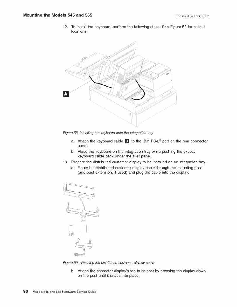
12. To install the keyboard, perform the following steps. See Figure 58 for callout
locations:
a. Attach the keyboard cable �A� to the IBM PS/2® port on the rear connector
panel.
b. Place the keyboard on the integration tray while pushing the excess
keyboard cable back under the filler panel.
13. Prepare the distributed customer display to be installed on an integration tray.
a. Route the distributed customer display cable through the mounting post
(and post extension, if used) and plug the cable into the display.
b. Attach the character display’s top to its post by pressing the display down
on the post until it snaps into place.
Figure 58. Installing the keyboard onto the integration tray
Figure 59. Attaching the distributed customer display cable
Mounting the Models 545 and 565 Update April 23, 2007
90 Models 545 and 565 Hardware Service Guide

14. To install a distributed customer display or an APA display, perform the
following steps:
a. Route the display cable �F� through hole �D�, as shown in Figure 60. You
might need to place the display on its side to connect the display cable to
the system unit rear connector panel.
b. Route the display cable to the rear connector panel, passing it under the
cable-tie bar, and plug it into the 15-pin serial connector.
c. Attach the distributed customer display �A� to the cash drawer at location
�B� with two thumbscrews �C�.
15. Plug the AC power cord to the power supply.
16. Connect the peripheral cables to the appropriate ports on the SurePOS 500
rear connector panel. Make the connections on the bottom row of the panel
first and work upward. See “Connectors, power, and brightness controls” on
page 5.
Notes:
a. If you are routing the cables under the counter, route all cables (including
the AC power cord) through the cable-access hole.
b. If you are routing the cables on top of the counter, route all cables out the
rear of the system. Lay the cables flat along the countertop.
17. Use tie-wraps to secure cables to the integration tray.
18. Replace the rear cover and install the rear filler panel.
19. Attach the cash-drawer rear cover by aligning the tabs with the buttons, and
push in on the cover.
20. Plug the system and printer AC power cords into an AC outlet.
Figure 60. Installing the distributed customer display onto the integration tray
Mounting the Models 545 and 565Update April 23, 2007
Chapter 4. Mounting the SurePOS 500 Models 545 and 565 91

21. After your installation is complete, press the printer power switch under the
printer cover to power on the printer.
22. Switch ON the power and verify that the system is operating correctly by
checking the indicator lights (LEDs) on the front of the touch screen.
23. Install your software. Refer to IBM SurePOS Model 545 and 565 Operating
System Installation Guide.
Mounting the Models 545 and 565 Update April 23, 2007
92 Models 545 and 565 Hardware Service Guide
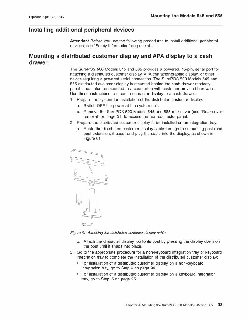
Installing additional peripheral devices
Attention: Before you use the following procedures to install additional peripheral
devices, see “Safety Information” on page xi.
Mounting a distributed customer display and APA display to a cash
drawer
The SurePOS 500 Models 545 and 565 provides a powered, 15-pin, serial port for
attaching a distributed customer display, APA character-graphic display, or other
device requiring a powered serial connection. The SurePOS 500 Models 545 and
565 distributed customer display is mounted behind the cash-drawer modesty
panel. It can also be mounted to a countertop with customer-provided hardware.
Use these instructions to mount a character display to a cash drawer.
1. Prepare the system for installation of the distributed customer display.
a. Switch OFF the power at the system unit.
b. Remove the SurePOS 500 Models 545 and 565 rear cover (see “Rear cover
removal” on page 31) to access the rear connector panel.
2. Prepare the distributed customer display to be installed on an integration tray.
a. Route the distributed customer display cable through the mounting post (and
post extension, if used) and plug the cable into the display, as shown in
Figure 61.
b. Attach the character display top to its post by pressing the display down on
the post until it snaps into place.
3. Go to the appropriate procedure for a non-keyboard integration tray or keyboard
integration tray to complete the installation of the distributed customer display:
v For installation of a distributed customer display on a non-keyboard
integration tray, go to Step 4 on page 94.
v For installation of a distributed customer display on a keyboard integration
tray, go to Step 5 on page 95.
Figure 61. Attaching the distributed customer display cable
Mounting the Models 545 and 565Update April 23, 2007
Chapter 4. Mounting the SurePOS 500 Models 545 and 565 93

4. To install a distributed customer display �D� on a non-keyboard integration tray,
perform the following steps:
a. Remove the filler panels �A� and �B� (two) and the rear modesty panel �C�
from the integration tray, as shown in Figure 62.
b. Remove one of the two plugs �E� in the rear modesty panel. Figure 62
shows one plug removed.
c. Route the character display cable through the hole in the modesty panel.
You may need to lay the display on its side to connect the display cable to
the rear connector panel.
d. Route the character display cable to the rear connector panel. Plug it into
the 15-pin serial connector.
e. Reinstall the rear cover of the SurePOS 500 Model 514 (see “Rear cover
removal” on page 31).
f. Reinstall the filler panels �B�, and then install �A�, as shown in Figure 62.
g. Attach the post, through the modesty cover �C� to the cash drawer with 2
thumbscrews �F�. Snap the entire unit into place at the rear of the tray.
Figure 62. Attaching the distributed customer display to the system unit
Mounting the Models 545 and 565 Update April 23, 2007
94 Models 545 and 565 Hardware Service Guide

5. To install a distributed customer display on a keyboard integration tray, perform
the following steps:
a. Route the character display cable through the hole behind mounting post as
shown in Figure 63. You might need to lay the display on its side to connect
the display cable to the system unit rear connector panel.
b. Route the distributed customer display cable �F� to the rear connector
panel, passing it under the cable-tie bar. Plug it into the 15-pin serial
connector.
c. Attach the distributed customer display �A� to the cash drawer mounting
post with two thumbscrews �C�. Snap the entire unit into place at the rear of
the tray, as shown in Figure 63.
Installing IBM 4610 SureMark Models TF6 or TF7 printers
Note: Service for the IBM SurePOS Model 4951, Model 514 includes the IBM 4610
SureMark printer.
The IBM 4610 SureMark Model TF6 and TF7 (4610 TF6 or TF7) are the smaller
4610 models that contain only a thermal customer receipt station. These models do
not support document printing. For detailed information about these printers, see
the IBM 4610 SureMark Point-of-Sale Printers User’s Guide.
The 4610 TF6 or TF7 can be installed as a freestanding unit, attached to a
countertop integration tray, or attached to a cash drawer integration tray. Attaching
the 4610 TF6 or TF7 to a non-keyboard integration tray is different than attaching it
to a keyboard integration tray:
v For the non-keyboard integration tray, the 4610 TF6 or TF7 is attached to a
mounting plate and then attached to the non-keyboard integration tray.
Figure 63. Installing the distributed customer display onto the keyboard integration tray
Mounting the Models 545 and 565Update April 23, 2007
Chapter 4. Mounting the SurePOS 500 Models 545 and 565 95

v For the keyboard integration tray, the 4610 TF6 or TF7 is set into a plastic printer
base and then set on the keyboard integration tray.
Figure 64 shows the 4610 TF6 or TF7 printer connectors.
�A� Power supply port (RS-232 only) �D� Cash drawer connector
�B� RS-232 port or Powered USB port �E� RS-232 mode switch
�C� (Not used on the SurePOS 500 Models
545 and 565)
To install the 4610 TF6 or TF7 printer, perform the following steps:
1. Switch OFF the power at the system unit.
2. Remove the SurePOS 500 rear cover (see “Rear cover removal” on page 31).
3. Check the printer RS-232 mode-switch setting for the printer. It is near the rear
cable connections. See �E� in Figure 64 for switch location. For switch settings,
see the IBM 4610 SureMark Point-of-Sale Printers User’s Guide.
4. Connect and route the RS-232 communication cable or Powered USB cable �A�
and the power supply cable �B� as shown in Figure 65 on page 97.
A
B
C
E
D
Figure 64. 4610 TF6 or TF7 printer connector locations
Mounting the Models 545 and 565 Update April 23, 2007
96 Models 545 and 565 Hardware Service Guide

5. Connect any other signal cables for I/O devices to the correct ports.
6. If you are installing a freestanding printer, route the cables to the rear connector
panel on the SurePOS 500 Models 545 and 565 system unit. Pass the cables
under the cable-tie bar, and plug it into one of the standard serial ports.
7. Go to the appropriate procedure for non-keyboard integration tray or keyboard
integration tray mounting of the 4610 TF6 or TF7 printer:
v If you are installing a 4610 TF6 or TF7 printer on a non-keyboard integration
tray, continue with Step 8.
v If installing a 4610 TF6 or TF7 printer on a keyboard integration tray, continue
with Step 11 on page 88.
8. To install a 4610 TF6 or TF7 printer on a non-keyboard integration tray, perform
the following steps:
a. Attach the printer mounting plate to the bottom of the printer. The mounting
plate slides into the two bottom slots of the printer.
b. The procedure for mounting the printer to a non-keyboard integration tray is
the same for countertop or cash drawer. With the mounting plate attached to
the printer, slide the front of the printer mounting plate into the slots located
A
C
B
Figure 65. Attaching and routing the cables to the printer.
Figure 66. Attaching the 4610 TF6 or TF7 printer mounting plate for a non-keyboard
integration tray
Mounting the Models 545 and 565Update April 23, 2007
Chapter 4. Mounting the SurePOS 500 Models 545 and 565 97

toward the front of the integration tray. Secure the printer by tightening the
two thumbscrews on the mounting plate to the tray.
c. Route the RS-232 cable �A� to the rear connector panel of the system unit
as shown in Figure 67. Plug it into one of the three standard serial ports on
the system unit.
d. Route the printer power cord �B� toward the system and out through the
hole in the integration tray, as shown in Figure 67.
Note: When routing the printer and power cables, make sure that the
cables are routed inside the mounting plate screws to enable correct
installation of the filler panels.
BA
Figure 67. 4610 TF6 or TF7 cable routing
Mounting the Models 545 and 565 Update April 23, 2007
98 Models 545 and 565 Hardware Service Guide

Appendix A. Field replaceable units
How to use the FRU catalog . . . . . . . . . . . . . . . . . . . . 99
Assembly 1: Models 545 and 565 . . . . . . . . . . . . . . . . . 100
Assembly 2: Countertop and cash drawer keyboard integration tray and filler
panels . . . . . . . . . . . . . . . . . . . . . . . . . . . 104
Assembly 3: Optional peripherals . . . . . . . . . . . . . . . . . . 106
Assembly 4: Countertop non-keyboard integration tray and filler panels . . . . 108
Assembly 5: Cash drawer non-keyboard integration tray and filler panels . . . 110
This chapter contains field-replaceable part number information the SurePOS 500
Models 545 and 565.
How to use the FRU catalog
This parts listing contains reference drawings and a corresponding index for all field
replaceable parts. The index provides the part number, the quantity required (units),
and a description of the part.
Listed below is additional information about the parts assembly index.
SIMILAR ASSEMBLIES
If two assemblies contain a majority of identical parts, they are broken down
on the same list. Common parts are shown by one index number. Parts
specific to one or the other of the assemblies are listed separately and
identified by description.
AR (As Required) in the Units column indicates that the quantity is not the
same for all machines.
NP (Non-Procurable) in the Units column indicates that the part is
non-procurable and that the individual parts or the next higher assembly
should be ordered.
NR (Not Recommended) in the Units column indicates that the part is
procurable, but not recommended for field replacement, and that the next
higher assembly should be ordered.
R (Restricted) in the Units column indicates the part has a restricted
availability.
INDENTURE
The indenture is marked by a series of dots located before the parts
description. The indenture indicates the relationship of a part to the next
higher assembly.
No Dot Main assembly
One Dot Detail parts of a main assembly
One Dot Subassembly of the main assembly
Two dots Detail part of a one-dot subassembly
Two dots Subassembly of a one-dot subassembly
Three dots Detail part of a two-dot subassembly
Update April 23, 2007
© Copyright IBM Corp. 2006, 2007 99
|

Assembly 1: Models 545 and 565
1
4
5
6
7
8
9
10
11
12
13
14
15
16
17
18
19
20
21
23
24
25
26
27
28
29
3
2
22
Field-replaceable units Update April 23, 2007
100 Models 545 and 565 Hardware Service Guide

Asm–Index
PartNumber Units Description
1–1 42V3886 Front bezel assembly, 12 in.
–1 42V3887 Front bezel assembly, 15 in.
–1 42V3888 Front bezel assembly, 17 in.
–2 12X1000 Tablet assembly, 12 in.
–2 12X1001 Tablet assembly, 15 in.
–2 12X1002 Tablet assembly, 17 in.
–3 42V3889 LCD assembly, 12 in.
–3 42V3890 LCD assembly, 15 in.
–3 42V3891 LCD assembly, 17 in.
–4 42V3897 MSR hole plug
–5 42V3893 Touch cable door, 12 in.
–5 42V3894 Touch cable door, 15 in.
–5 42V3895 Touch cable door, 17 in.
–6 42V3892 Operator card kit, 12 in., 17 in.
–6 12X1036 Operator card kit, 15 in.
–7 42V3924 Top, center cover kit
– 41D0171 Power button cover
–8 42V3937 Processor fan/fan bracket
–9 42V3925 Hinge cover, 12 in. and 15 in.
–9 42V3926 Hinge cover, 17 in.
–10 42V3922 Hinge, 12 in. and 15 in.
–10 42V3923 Hinge, 17 in.
–11 42V3927 HDD cover with speaker (model 565, E65 only)
–11 42V3928 HDD cover, no speaker (model 545, E45 only)
–12 42V3943 HDD assembly (HDD, bracket, 4 screws)
– 42V3980 HDD bracket
– 41A3641 HDD
– 42V3944 HDD cable kit
–13 42V3931 Side cover kit
–14 42V3950 PC card door
–15 42V3953 Audio port cover
–16 42V3930 Speaker ESD shield (model 565, E65 only)
–17 40N5755 Speaker (model 565, E65 only)
–18 42V3945 Tablet cable, 12 in. and 15 in.
–19 42V3936 HDD fan kit (bracket, fan, cable)
–18 42V3946 Tablet cable, 17 in.
– 42V3969 System board tray
–20 42V3948 System board assembly, no audio, no PCMCIA (model 545, E45 only)
–20 42V3949 System board assembly, audio, PCMCIA (model 565, E65 only)
–21 42V3938 Processor heat sink
– 42V3939 Processor 2.53 GHz
–22 39X8908 Modular flash drive
–23 12X1009 Video card
–24 12X1110 Rear cover
–25 42V3935 Tailgate assembly
– 42V3947 Speaker extension cable (model 565, E65 only)
–26 42V3932 Cable tie bar
–27 42V3933 Power supply latch arm
–28 42V3682 Power supply
– 42V3951 Power supply EMC shield
–29 42V3940 Base, 12 in. and 15 in.
–29 42V3941 Base, 17 in.
– 45P6222 Battery
Assembly 1: (continued)Update April 23, 2007
Appendix A. Field replaceable units 101
||||
||||
||||
||||||||
||||
||||||||||||
||||
||||||||
||||
||||||||
||||
||||
||||

Asm–Index
PartNumber Units Description
– 42V3952 Screw kit
– 42V3956 Memory, 512 MB
– 42V3957 Memory, 1 GB
– 41D9746 USB memory key
Assembly 1: (continued) Update April 23, 2007
102 Models 545 and 565 Hardware Service Guide

Field-replaceable unitsUpdate April 23, 2007
Appendix A. Field replaceable units 103
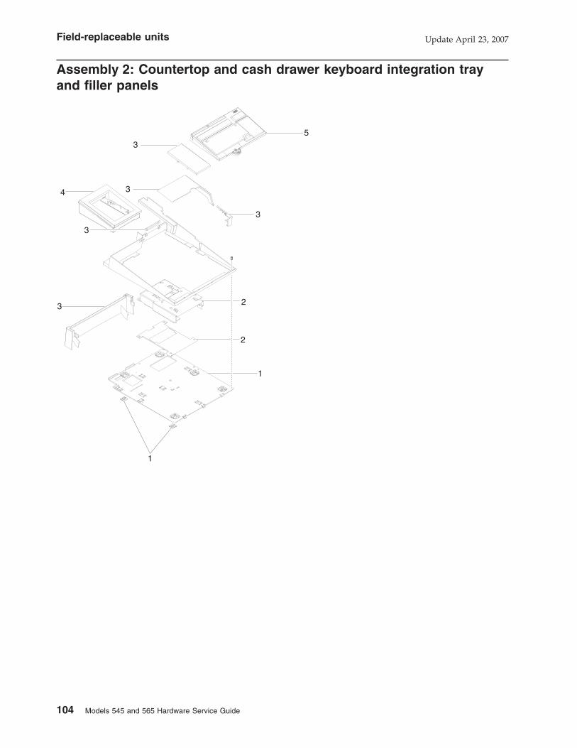
Assembly 2: Countertop and cash drawer keyboard integration tray
and filler panels
3
3
4 3
3
3 2
2
1
1
5
Field-replaceable units Update April 23, 2007
104 Models 545 and 565 Hardware Service Guide

Asm–Index
PartNumber Units Description
2– Countertop and cash drawer keyboard integration tray and filler panels
–1 41D0214 1 FRU, plate/fence ASM, wide cash drawer or countertop (includes hardware)
– 1 v ASM, wide cash drawer plate (includes hardware)
– 1 v - M6X8 screws, cash drawer mount
– 1 v - Fence, wide
– 1 v - M3X5 screws, fence mounting
– 1 v - Feet, rubber
–2 42V3964 1 FRU, plate ASM, terminal mounting
– 1 v ASM, terminal mount
– 1 v - Plate, terminal mount insulator
– 1 v - Washer, insulating
– 1 v - M6X12 screws, terminal mount
–3 42V3965 5 FRU, filler panels, wide and countertop
– 1 v Cover, keyboard filler, retail keyboard
– 1 v Cover, terminal filler, wide tray and countertop
– 1 v Cover, wide CD rear curtain
– 1 v Fence, plug
–4 47P9273 1 FRU, iron gray printer footprint adapter, SST to 4610
– 1 v ASM, iron gray printer footprint adapter
– 1 v - Base, SST to 4610 footprint, iron gray
– 1 v - Panel, SST to 4610 footprint, iron gray
– 1 v - Feet, printer base
– 41D0216 1 FRU, retail integration, installation hardware kit (not shown)
– 1 v Hardware kit, retail integration
– 1 v - M3X5 screws, fence mounting (6)
– 1 v - M5X10 screws, system unit mounting (4)
– 1 v - M6X12 screws, terminal mounting (4)
– 1 v - Washer, insulation (for terminal mount screws) (4)
– 1 v - M6X8 screws, CD plate mounting (4)
– 1 v - Feet, CD plate countertop mounting (5)
–5 14R0157 Wide keyboard filler panel. See the "CANPOS keyboard with integrated pointing
devices" description in the Options and Input/Output Service Guide, publication
GC30-9737.
Assembly 2: (continued)Update April 23, 2007
Appendix A. Field replaceable units 105

Assembly 3: Optional peripherals
4
3
2
1
Field-replaceable units Update April 23, 2007
106 Models 545 and 565 Hardware Service Guide

Asm–Index
PartNumber Units Description
3–1 42V3960 MSR, 3-track
–1 42V3961 MSR, JUCC
–2 42N5755 Speaker
–3 42V3958 Display, integrated 2x20
–4 42V3959 VFD housing, integrated
Assembly 3: (continued)Update April 23, 2007
Appendix A. Field replaceable units 107

Assembly 4: Countertop non-keyboard integration tray and filler panels
4
3
6
5
1
4
4
2
4
6
Field-replaceable units Update April 23, 2007
108 Models 545 and 565 Hardware Service Guide

Asm–Index
PartNumber Units Description
4– Countertop non-keyboard integration tray and filler panels
–1 41D0261 Plate/fence assembly, counter top mounting
–2 41D0211 Plate assembly, printer mounting
–3 42V3966 Plate assembly, terminal mounting (includes screw)
–4 42V3967 Filler panel kit
–5 Feet, rubber (5), included in Hardware kit
–6 12X1129 Printer filler panel kit for non-keyboard trays
– 41D0212 Hardware, non-keyboard integration tray (kit - includes feet and screws, not
illustrated)
– –
Assembly 4: (continued)Update April 23, 2007
Appendix A. Field replaceable units 109

Assembly 5: Cash drawer non-keyboard integration tray and filler
panels
3
4
2
1
5
4
6
4
6
Field-replaceable units Update April 23, 2007
110 Models 545 and 565 Hardware Service Guide

Asm–Index
PartNumber Units Description
5– Cash drawer non-keyboard integration tray and filler panels
–1 41D0210 1 Plate and fence, cash drawer mount
–2 41D0211 1 Plate, printer mounting
–3 42V3966 1 Plate, terminal mounting
–4 42V3967 1 Panels, filler
–5 20P0308 1 Cover, modesty (and 2 plugs)
–6 12X1129 1 Printer filler panel kit, non-keyboard
– 41P0212 1 Hardware, non-keyboard integration tray (kit - includes screws, not illustrated)
– –
For power cords, see Appendix B, “Power cords,” on page 113.
Assembly 5: (continued)Update April 23, 2007
Appendix A. Field replaceable units 111

Update April 23, 2007
112 Models 545 and 565 Hardware Service Guide

Appendix B. Power cords
Table 19. Power cord lengths and part numbers by country
Part number Length Country
39M5066 4.3 m Argentina
39M5093 4.3 m Bahamas, Barbados, Bermuda, Bolivia,
Canada, Cayman Islands, Columbia, Costa
Rica, Dominican Rep., El Salvador, Ecuador,
Guatemala, Haiti, Honduras, Jamaica, Mexico,
Netherlands Antilles, Nicaragua, Panama,
Peru, Philippines, U.S., Venezuela
39M5100 4.3 m Australia, New Zealand
39M5204 4.3 m China (PR)
39M5211 4.3 m Korea
39M5121 4.3 m Europe
39M5128 4.3 m Denmark
39M5142 4.3 m South Africa
39M5149 4.3 m United Kingdom, Hong Kong
39M5156 4.3 m Switzerland
39M5163 4.3 m Chile, Italy
39M5170 4.3 m Israel
39M5191 4.3 m Japan
39M5079 4.3 m (non-locking) United States
39M5077 1.8 m United States, Chicago
39M5107 4.3 m (locking) United States
Update April 23, 2007
© Copyright IBM Corp. 2006, 2007 113

Power cords Update April 23, 2007
114 Models 545 and 565 Hardware Service Guide

Appendix C. System specifications and planning information
Physical specifications and dimensions . . . . . . . . . . . . . . . 115
Dimensions with trays . . . . . . . . . . . . . . . . . . . . . 116
Dimensions of unit with 12-inch display . . . . . . . . . . . . . . 118
Dimensions of unit with 15-inch display . . . . . . . . . . . . . . 119
Dimensions of unit with 17-inch display . . . . . . . . . . . . . . 120
Power requirements and consumption . . . . . . . . . . . . . . . . 121
Power . . . . . . . . . . . . . . . . . . . . . . . . . . . 121
Port power ratings . . . . . . . . . . . . . . . . . . . . . . 121
Connector-pin assignments . . . . . . . . . . . . . . . . . . . . 122
External connectors . . . . . . . . . . . . . . . . . . . . . . 122
Speaker connector . . . . . . . . . . . . . . . . . . . . . 122
MSR connector . . . . . . . . . . . . . . . . . . . . . . 122
USB port connectors . . . . . . . . . . . . . . . . . . . . 124
Keyboard connector . . . . . . . . . . . . . . . . . . . . 124
Mouse connector . . . . . . . . . . . . . . . . . . . . . 125
Microphone connector . . . . . . . . . . . . . . . . . . . . 125
Headphone connector . . . . . . . . . . . . . . . . . . . . 125
Serial connectors . . . . . . . . . . . . . . . . . . . . . 125
Ethernet connector . . . . . . . . . . . . . . . . . . . . . 127
External video connector . . . . . . . . . . . . . . . . . . . 128
Cash drawer connector (2) . . . . . . . . . . . . . . . . . . 129
Integrated customer display connector . . . . . . . . . . . . . . 129
Temperature, humidity, and altitude limits . . . . . . . . . . . . . . . 130
This appendix provides information on power subsystems, and environmental
requirements.
Physical specifications and dimensions
The SurePOS 500 Series physical specifications are described in Table 20.
Table 20. Height, weight and depth of the SurePOS 500 Models 545 and 565
4846 Weight
Height: Tablet
at 15 degrees
Height
maximum
Depth: Tablet
at 15 degrees
Depth: Tablet
at 60 degrees
Width
Tower
and 12-in.
tablet
11.3 kg (25 lbs) 357.9 mm (14.0
in.)
374.1 mm (14.7
in.)
316.8 mm (12.5
in.)
385.8 mm (15.2
in.)
307.9 mm
(12.12 in.)
Tower
and 15-in.
tablet
12.2 kg (27 lbs) 381.8 mm (15.0
in.)
393.6 mm (15.5
in.)
324.4 mm (12.8
in.)
405.8 mm (15.9
in.)
369 mm (14.5
in.)
Tower
and 17-in.
tablet
14.51 kg (32
lbs)
404.5 mm
(15.93 in.)
414.6 mm
(16.32 in.)
335.2 mm (13.2
in.)
423.9 mm (16.7
in.)
402.3 mm
(15.83 in.)
Table 21. Weights of integrated, distributed displays and MSR
Component Weight
Integrated 2x20 display 0.2 kg (0.38 lbs)
Distributed 2x20 display 0.5 kg (1.2 lbs)
Distributed APA display 0.7 kg (1.6 lbs)
Update April 23, 2007
© Copyright IBM Corp. 2006, 2007 115
||
||
|||
||||||||||||
|
||
||
||
||
||

Table 21. Weights of integrated, distributed displays and MSR (continued)
Component Weight
MSR (three-track or JUCC) 0.16 kg (0.41 lbs)
Dimensions with trays
Table 22 provides the dimensions shown by measurements A and B in Figure 68,
Figure 69 on page 117, and Figure 70 on page 117.
Note: The tablet is shown at 15 degrees.
Table 22. SurePOS 500 Models 545 and 565 dimensions. See Figure 68 and Figure 69 on page 117 to locate
Measurement A and B
Product with 12 in. tablet and the
following:
Measurement A Measurement B
Counter top tray 382.4 mm (15.1 in.) 478.6 mm (18.8 in.)
Cash drawer tray 493.5 mm (19.4 in.) 480.9 mm (18.9 in.)
Retail tray 527.4 mm (20.8 in.) 489.2 mm (19.2 in.)
Product with 15 in. tablet and the following:
Counter top tray 406.2 mm (15.9 in. ) 509.2 mm (20.0 in.)
Cash drawer tray 517.3 mm (20.4 in.) 511.4 mm (20.1 in)
Retail tray 551.1 mm (21.7 in.) 519.7 mm (20.5 in.)
Product with 17 in. tablet and the following:
Counter top try 428.9 mm (16.9 in.) 525.9 mm (20.7 in.)
Cash drawer 540 mm (21.3 in.) 528.1 mm (20.8 in.)
Retail tray 573.8 mm (22.6 in.) 536.4 mm (21.1 in.)
43.9mm (1.7 in.)
449.5mm (17.7 in.)
7.2mm (.28 in.)
B
31.2
mm
(1.
2 in
.)
39.6
mm
(1.
5 in
.)
428m
m (
17.7
in.)
491.
5mm
(19
.3 in
.)
523.9mm (20.6 in.)
A
Figure 68. Dimensions of SurePOS Models 545 and 565 with retail tray. The tablet is shown at 15 degrees.
System specifications and planning information Update April 23, 2007
116 Models 545 and 565 Hardware Service Guide
|
||
|||
|
||
|
|||
||||
|||
|||
|||
|
|||
|||
|||
|
|||
|||
||||||

441.9mm (17.4 in.)
B
43.9mm (1.7 in.)
340.5mm (13.4 in)
356.2mm (14.0 in.)
346.
6mm
(13
.6 in
)
39.6
mm
(1.
5 in
)
31.2
mm
(1.
2 in
.)
A
Figure 69. Dimensions of SurePOS Models 545 and 565 with counter top tray. The tablet is shown at 15 degrees.
3.4mm (.13 in.)
449.5mm (17.7 in.)
43.9mm (1.7 in.)
B
415.
4mm
(17
.7 in
.)
457.
65m
m (
18.0
in.)
39.6
mm
(1.
5 in
.)
31.2
3mm
(1.
2 in
.)
A
Figure 70. SurePOS Models 545 and 565 with cash drawer tray. The tablet is shown at 15 degrees.
System specifications and planning informationUpdate April 23, 2007
Appendix C. System specifications and planning information 117
||

Dimensions of unit with 12-inch display
212mm (8.35 in.)
242.3mm (9.54 in.)
307.9mm (12.1 in.)
351.8mm (13.9 in.)
357.
9mm
(14
.09
in.)
31.2
mm
(31
.2 in
.)
15°
228.2mm (8.98 in.)
247.7mm (9.75 in)
316.8mm (12.5 in.)
322.
1mm
(12
.68
in.)
362m
m (
14.2
5 in
.)
389.
1mm
(15
.32)
212m
m (
8.35
in.)
201.
6mm
(7.
94 in
.)
Figure 71. Dimensions of unit with 12-inch display
System specifications and planning information Update April 23, 2007
118 Models 545 and 565 Hardware Service Guide
|
||

Dimensions of unit with 15-inch display
362m
m (
14.2
5 in
.
322.
1mm
(12
.68
in.)
412.
4mm
(16
.24
in.)
228.2mm (8.98 in.)
247.6mm (9.75 in.)
324.4mm (12.77 in.)
15°212mm (8.35 in.)
242.3mm (9.54 in.)
369mm (14.5 in.)
381.
8mm
(15
.03
in.)
30.6
mm
(1.
2in)
212m
m (
8.35
in.)
201.
6mm
(7.
94 in
.)
Figure 72. Dimensions of unit with 15-inch display
System specifications and planning informationUpdate April 23, 2007
Appendix C. System specifications and planning information 119
|
||

Dimensions of unit with 17-inch display
362m
m (
14.2
5 in
.)
322.
1mm
(12
.68
in.)
433.
6mm
(17
.07)
258.2mm (10.17 in.)
277.6mm (10.93 in.)
335.2mm (13.19 in.)
15°
201.
6mm
(7.
94 in
.)
212m
m (
8.35
in.)
242.
3mm
(9.
54 in
.)
212mm (8.35 in.)402.3mm (15.83 in.)
446.2mm (17.6 in.)
404.
5mm
(15
.93
in.)
29.1
mm
(1.
15 in
.)
System specifications and planning information Update April 23, 2007
120 Models 545 and 565 Hardware Service Guide
|
|
||

Power requirements and consumption
This section describes the power requirements and power consumption of the
SurePOS 500 Series.
Power
Table 23. Input voltage, frequency
Input Frequency
100 – 127 V AC 50 or 60 Hz
200 – 240 V AC 50 or 60 Hz
Table 24. SurePOS 500 Series Models 545 and 565 power supply
Nominal output voltage Tolerance Rated Current
+5.0 V AUX ±5% 2.0 A
+5.0 V MAIN +5/-4% 8.0 A
+12.0 V ±5% 12.0 A
+3.3 V ±5% 6.0 A
-12.0 V ±10% 0.3 A
+25.3 V ±4% 3.0 A
Table 25. Power consumption
State: Usage:
Off 4 W
Standby 80 W
Suspend Not supported
On (idle, no I/O) 120 W
On (idle, I/O: cash drawer, MSR, 2/20,
printer)
125 W
On (max, printing) 170 W
Input 100 - 127, 200 - 240 V AC (nominal), 50 or
60 Hz (+/- 3 Hz)
Voltage/Frequency Sinusoidal, trapezoidal, or square wave
inputs
Maximum kVA 0.3
AC Input IEC 320 C14, unshielded right angle type
Connector/Cable leakage current 3.5 ma maximum
Inrush < 30 A (peak, first cycle)
Port power ratings
v Only one cash drawer may be activated at any instance in time.
v Hot plugging of powered USB devices, especially printers, is not supported.
Some powered USB devices create surge currents that may cause the system
power supply to initiate over-current shut down.
Note: All ports provide protection against power surges.
System specifications and planning informationUpdate April 23, 2007
Appendix C. System specifications and planning information 121

Table 26. Port current ratings
Port/Name Port Voltage Ratings Maximum Current
Distributed VFD/Serial 5 V 0.95 A
12 V 0.65 A
USB (x6) 5 V 0.5 A
USB Plus Power 5 V 0.5 A
12 V 1.5 A
24 V 3.0 A continuous
5.0 A peak
Keyboard and Mouse 5 V 0.6 A
3A, 3B/cash drawer 24 V 1 A for 200 msec
Connector-pin assignments
This following sections list the connector-pin assignments for the external and
internal connectors.
External connectors
The following sections show the connector-pin assignments for external connectors.
Speaker connector
5 1
Table 27. Speaker connector-pin assignments
Pin Connect
1 +12 V AC
2 Ground
3 Line Left
4 Line Right
5 Ground
MSR connector
8 1
Table 28. MSR connector-pin assignments
Pin Connector
1 +5 V dc
2 Serial data out
3 Serial data in
System specifications and planning information Update April 23, 2007
122 Models 545 and 565 Hardware Service Guide
|
||
|||

Table 28. MSR connector-pin assignments (continued)
Pin Connector
4 Ground
5 KBD enable
6 Keyboard data
7 Keyboard clock
8 Ground
Connector-pin assignmentsUpdate April 23, 2007
Appendix C. System specifications and planning information 123

USB port connectors
4321
Table 29. USB port connector-pin assignments
Unpowered USB
Pin Connector
1 5 V bus
2 −Data
3 +Data
4 Ground
Note: Tablet USB ports are USB 1.1 compliant; side and back USB ports are USB
2.0 compliant.
Table 30. USB port connector-pin assignments
Powered USB
Pin Connector
Shell Shield
1 5 V Vbus
2 −Data
3 +Data
4 Ground
5 Ground
6 Vplus (12 V or 24 V)
7 Vplus (12 V or 24 V)
8 Ground
Keyboard connector
12
34
56
Table 31. Keyboard and mouse connector-pin assignments
Pin Signal I/O Pin Signal I/O
1 Keyboard data I/O 4 +5 V Main I/O
3 Ground 5 Keyboard clock
Connector-pin assignments Update April 23, 2007
124 Models 545 and 565 Hardware Service Guide

Mouse connector
12
34
56
Table 32. Keyboard and mouse connector-pin assignments
Pin Signal I/O Pin Signal I/O
2 Mouse data I/O 4 +5 V Main I/O
3 Ground 6 Mouse clock
Microphone connector
The microphone connector is on the tower, at the lower left, below the side
connector panel.
Ground
Signal
5v
Table 33. Microphone connector-pin assignments
Pin Signal
Tip Signal
Ring +5 V dc
Base Ground
Headphone connector
The headphone connector is on the tower, at the lower left, below the side
connector panel, with the microphone connector.
Table 34. Headphone connector-pin assignments
Pin Signal
Tip Left channel audio
Ring Right channel audio
Base Ground
Serial connectors
RJ-45 Connectors (3):
8 1
Connector-pin assignmentsUpdate April 23, 2007
Appendix C. System specifications and planning information 125

Table 35. RJ-45 connector-pin assignments
Pin Signal Pin Signal
1 DSR 5 RXD
2 CD 6 TXD
3 DTR 7 CTS
4 Ground 8 RTS
Connector-pin assignments Update April 23, 2007
126 Models 545 and 565 Hardware Service Guide

15-pin serial connector: The 15-pin serial connector is a female connector.
8
15 9
1
Table 36. Assignments for 15-pin serial connector
Pin Connector Pin Connector
1 Carrier detect 8, 9 +12 V dc at 0.5 A
maximum
2 Receive data 11 Distributed display present
3 Transmit data 12 Data set ready
4 Data terminal ready 13 Request to send
5 Ground 14 Clear to send
6 Ground 15 Ring indicate
7, 10 +5 V dc at 0.5 A maximum
Ethernet connector
8 1
Table 37. Ethernet connector-pin assignments
Pin Signal I/O Pin Signal I/O
1 TxD+ O 5 Ground
2 TxD− O 6 RxD− I
3 RxD+ I 7 Ground
4 Ground 8 Ground
Connector-pin assignmentsUpdate April 23, 2007
Appendix C. System specifications and planning information 127

External video connector
5 1
6
1115
10
Table 38. Assignment of external-video connector pins
Pin Connector Pin Connector
1 Red 9 No connection
2 Green 10 Ground
3 Blue 11 No connection
4 No connection 12 Monitor ID1
5 Ground 13 Horizontal sync
6 Red ground 14 Vertical sync
7 Green ground 15 Monitor ID3
8 Blue ground
Connector-pin assignments Update April 23, 2007
128 Models 545 and 565 Hardware Service Guide
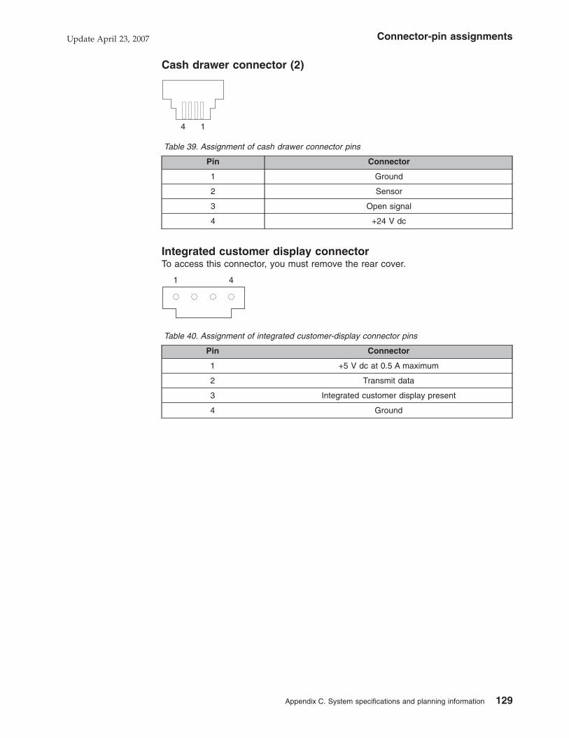
Cash drawer connector (2)
4 1
Table 39. Assignment of cash drawer connector pins
Pin Connector
1 Ground
2 Sensor
3 Open signal
4 +24 V dc
Integrated customer display connector
To access this connector, you must remove the rear cover.
41
Table 40. Assignment of integrated customer-display connector pins
Pin Connector
1 +5 V dc at 0.5 A maximum
2 Transmit data
3 Integrated customer display present
4 Ground
Connector-pin assignmentsUpdate April 23, 2007
Appendix C. System specifications and planning information 129

Temperature, humidity, and altitude limits
Table 41. Temperature, humidity, altitude limits
Condition
Temperature limits
(dry bulb)
Relative Humidity
Maximum wet bulb
temperature
Operating 5 to 40° C. 8 to 80 % 27° C.
Power Off 0 to 52° C. 5 to 95 % 27° C.
Storage 0 to 60° C. 5 to 100% 29° C.
This product is designed to operate up to 3050 m (10,000 ft.).
Connector-pin assignments Update April 23, 2007
130 Models 545 and 565 Hardware Service Guide

Appendix D. Notices
This information was developed for products and services offered in the U.S.A.
IBM may not offer the products, services, or features discussed in this document in
other countries. Consult your local IBM representative for information on the
products and services currently available in your area. Any reference to an IBM
product, program, or service is not intended to state or imply that only that IBM
product, program, or service may be used. Any functionally equivalent product,
program, or service that does not infringe any IBM intellectual property right may be
used instead. However, it is the user’s responsibility to evaluate and verify the
operation of any non-IBM product, program, or service.
IBM may have patents or pending patent applications covering the subject matter in
this document. The furnishing of this document does not give you any license to
these patents. You can send license inquiries, in writing, to:
IBM Director of Licensing
IBM Corporation
North Castle Drive
Armonk, NY 10504-1785
U.S.A.
For license inquiries regarding double-byte (DBCS) information, contact the IBM
Intellectual Property Department in your country or send inquiries, in writing, to:
IBM World Trade Asia Corporation
Licensing
2-31 Roppongi 3-chome, Minato-ku
Tokyo 106, Japan
The following paragraph does not apply to the United Kingdom or any other country
where such provisions are inconsistent with local law: INTERNATIONAL BUSINESS
MACHINES CORPORATION PROVIDES THIS PUBLICATION ″AS IS″ WITHOUT
WARRANTY OF ANY KIND, EITHER EXPRESS OR IMPLIED, INCLUDING, BUT
NOT LIMITED TO, THE IMPLIED WARRANTIES OF NON-INFRINGEMENT,
MERCHANTABILITY, OR FITNESS FOR A PARTICULAR PURPOSE. Some states
do not allow disclaimer of express or implied warranties in certain transactions,
therefore, this statement may not apply to you.
This information could include technical inaccuracies or typographical errors.
Changes are periodically made to the information herein; these changes will be
incorporated in new editions of the publication. IBM may make improvements and/or
changes in the product(s) and/or program(s) described in this publication at any
time without notice.
IBM may use or distribute any of the information you supply in any way it believes
appropriate without incurring any obligation to you.
Any references in this information to non-IBM Web sites are provided for
convenience only and do not in any manner serve as an endorsement of those
Web sites. The materials at those Web sites are not part of the materials for this
IBM product and use of those Web sites is at your own risk.
Information concerning non-IBM products was obtained from the suppliers of those
products, their published announcements or other publicly available sources. IBM
Update April 23, 2007
© Copyright IBM Corp. 2006, 2007 131

has not tested those products and cannot confirm the accuracy of performance,
compatibility or any other claims related to non-IBM products. Questions on the
capabilities of non-IBM products should be addressed to the suppliers of those
products.
This information is for planning purposes only. The information herein is subject to
change before the products described become available.
Update April 23, 2007
132 Models 545 and 565 Hardware Service Guide

Electronic emission notices
Federal Communications Commission (FCC) Statement
This equipment has been tested and found to comply with the limits for a Class A
digital device, pursuant to Part 15 of the FCC Rules. These limits are designed to
provide reasonable protection against harmful interference when the equipment is
operated in a commercial environment. This equipment generates, uses, and can
radiate radio frequency energy and, if not installed and used in accordance with the
instruction manual, may cause harmful interference to radio communications.
Operation of this equipment in a residential area is likely to cause harmful
interference, in which case the user will be required to correct the interference at
his own expense.
Properly shielded and grounded cables and connectors must be used in order to
meet FCC emission limits. IBM is not responsible for any radio or television
interference caused by using other than recommended cables and connectors or by
unauthorized changes or modifications to this equipment. Unauthorized changes or
modifications could void the user’s authority to operate the equipment.
This device complies with part 15 of the FCC Rules. Operation is subject to the
following two conditions: (1) this device may not cause harmful interference, and (2)
this device must accept any interference received, including interference that may
cause undesired operation.
Industry Canada Class A Emission Compliance Statement
This Class A digital apparatus complies with Canadian ICES-003.
Avis de conformité aux normes d’Industrie Canada
Cet appareil numérique de la classe A est conforme à la norme NMB-003 du
Canada.
European Union (EU) Mark of Conformity Statement
This product has been tested and found to comply with the limits for Class A
Information Technology Equipment according to European Standard EN 55022. The
limits for Class A equipment were derived for commercial and industrial
environments to provide reasonable protection against interference with licensed
communication equipment.
Warning: This is a Class A product. In a domestic environment this product may
cause radio interference in which case the user may be required to take adequate
measures.
Properly shielded and grounded cables and connectors must be used in order to
reduce the potential for causing interference to radio and TV communications and
to other electrical or electronic equipment. Such cables and connectors are
available from IBM authorized dealers. IBM cannot accept responsibility for any
interference caused by using other than recommended cables and connectors.
Germany
Zulassungsbescheinigung laut dem Deutschen Gesetz über die
elektromagnetische Verträglichkeit von Geräten (EMVG) vom 30. August 1995
(bzw. der EMC EG Richlinie 89/336).
Update April 23, 2007
Appendix D. Notices 133

Dieses Gerät ist berechtigt in Übereinstimmung mit dem Deutschen EMVG das
EG-Konformitätszeichen - CE - zu führen.
Verantwortlich für die Konformitätserklärung nach Paragraph 5 des EMVG ist die
IBM Deutschland Informationssysteme GmbH, 70548 Stuttgart.
Informationen in Hinsicht EMVG Paragraph 3 Abs. (2) 2:
Das Gerät erfüllt die Schutzanforderungen nach EN 50082–1 und EN 55022 Klasse A.
EN 55022 Klasse A Geräte müssen mit folgendem Warnhinweis versehen werden:
″Warnung: dies ist eine Einrichtung der Klasse A. Diese Einrichtung kann im
Wohnbereich Funkstörungen verursachen; in diesem Fall kann vom Betreiber
verlangt werden, angemessene Maβnahmen durchzuführen und dafür
aufzukommen.″
EN 50082–1 Hinweis:
″Wird dieses Gerät in einer industriellen Umgebung betrieben (wie in EN 50082–2
festgelegt), dann kann es dabei eventuell gestört werden. In solch einem Fall ist der
Abstand bzw. die Abschirmung zu der industriellen Störquelle zu vergröβern.″
Anmerkung:
Um die Einhaltung des EMVG sicherzustellen sind die Geräte, wie in den IBM
Handbüchern angegeben, zu installieren und zu betreiben.
Australia / New Zealand
Attention: This is a Class A product. In a domestic environment this product may
cause radio interference, in which case the user may be required to take adequate
measures.
Japanese power line harmonics compliance statement
Japanese Voluntary Control Council for Interference (VCCI) Statement
This product is a Class A Information Technology Equipment and conforms to the
standards set by the Voluntary Control Council for Interference by Technology
Equipment (VCCI). In a domestic environment this product may cause radio
interference in which case the user may be required to take adequate measures.
Update April 23, 2007
134 Models 545 and 565 Hardware Service Guide

Korean Communications Statement
Please note that this device has been approved for business purposes with regard
to electromagnetic interference. If you find this is not suitable for your use, you may
exchange it for a non-business purpose one.
Chinese Class A warning statement
Attention: This is a Class A product. In a domestic environment this product may
cause radio interference in which case the user may be required to take adequate
measures.
Taiwanese Class A warning statement
Update April 23, 2007
Appendix D. Notices 135

Taiwan contact information
IBM Taiwan Product Service Contact Info:
IBM Taiwan Corporation
3F, No 7, Song Ren Road, Taipei Taiwan
Telephone: 0800-016-888
Note: Cable ferrites are required to suppress radiated EMI emissions and shall not
be removed.
Taiwan recycle statement
Waste batteries, please recycle.
Electrostatic Discharge (ESD)
Attention: ESD damage can occur when there is a difference in charge between
the part, the product, and the service person. No damage will occur if the service
person and the part being installed are at the same charge level.
ESD Damage Prevention
Anytime a service action involves physical contact with logic cards, modules,
back-panel pins, or other ESD sensitive (ESDS) parts, the service person must be
connected to an ESD common ground point on the product through the ESD wrist
strap and cord.
The ESD ground clip can be attached to any frame ground, ground braid, green
wire ground, or the round ground prong on the AC power plug. Coax or connector
outside shells can also be used.
Handling Removed Cards
Logic cards removed from a product should be placed in ESD protective containers.
No other object should be allowed inside the ESD container with the logic card.
Attach tags or reports that must accompany the card to the outside of the container.
Update April 23, 2007
136 Models 545 and 565 Hardware Service Guide

Trademarks
The following are trademarks of International Business Machines Corporation in the
United States or other countries, or both:
IBM SurePoint
the IBM logo SurePOS
PS/2 Wake on LAN
SureMark
Microsoft, Windows, Windows NT, and the Windows logo are trademarks of
Microsoft Corporation in the United States, other countries, or both.
Celeron and Intel are trademarks of Intel corporation in the United States, or other
countries.
Java and all Java-based trademarks and logos are trademarks or registered
trademarks of Sun Microsystems, Inc. in the United States, or other countries, or
both.
Other company, product, or service names may be trademarks or service marks of
others.
Update April 23, 2007
Appendix D. Notices 137

Update April 23, 2007
138 Models 545 and 565 Hardware Service Guide

Appendix E. Safety information
Before you begin to install or service this product, read the following safety
information.
Safety Information-English
DANGER
To avoid a shock hazard, do not connect or disconnect any cablesor perform installation, maintenance, or reconfiguration of thisproduct during an electrical storm.
DANGER
To avoid shock hazard:
The power cord must be connected to a properly wired andearthed receptacle.
Any equipment to which this product will be attached must alsobe connected to properly wired receptacles.
DANGER
When possible, use one hand to connect or disconnect signalcables to prevent a possible shock from touching two surfaceswith different electrical potentials.
Update April 23, 2007
© Copyright IBM Corp. 2006, 2007 139

Caution:
A lithium battery can cause a fire, an explosion, or a severe burn. Do not
recharge, disassemble, heat above 100 degree C (212 degree F), solder directly
to the cell, incinerate, or expose the cell contents to water.
Keep away from children.
Replace only with the part number specified for this IBM product. Use of a
different battery may present a risk of fire or explosion. The battery connector is
polarized; do not attempt to reverse the polarity.
Dispose of the battery according to local regulations.
Safety information Update April 23, 2007
140 Models 545 and 565 Hardware Service Guide

Safety Information-Arabic
Safety informationUpdate April 23, 2007
Appendix E. Safety information 141

Safety information Update April 23, 2007
142 Models 545 and 565 Hardware Service Guide

Safety Information-Brazilian Portuguese
Safety informationUpdate April 23, 2007
Appendix E. Safety information 143

Cuidado:
Uma bateria de lítio pode causar incêndio, explosão ou queimaduras graves. Não
recarregue, desmonte ou aqueça acima de 100°C (212°F), não utilize solda
diretamente na célula, nem incinere ou exponha o conteúdo da célula à água.
Mantenha longe do alcance de crianças.
Substitua apenas pelo número de peça especificado para este produto IBM. A
utilização de uma bateria diferente representa risco de incêndio ou explosão. O
conector da bateria é polarizado; não tente reverter a polaridade.
Descarte a bateria de acordo com as regulamentações locais.
Safety information Update April 23, 2007
144 Models 545 and 565 Hardware Service Guide

Safety Information-French
Safety informationUpdate April 23, 2007
Appendix E. Safety information 145

Attention:
Prenez garde aux risques d’incendie, d’explosion ou de brûlures graves liés à
l’utilisation d’une pile au lithium. Ne la rechargez pas et ne la déamontez pas. Ne
l’exposez pas à une température supéeriure à 100 °C, ne la soudez pas, ne la
faites pas brûler et n’en exposez pas le contenu à l’eau.
Gardez la pile hors de portée des enfants.
Si vous la remplacez, commandez une pile de rechange de e. même référence.
Toute autre pile risquerait de prendre feu ou d’exploser. Le connecteur de la pile est
polarisé. N’essayez pas d’inverser la polarité.
Safety information Update April 23, 2007
146 Models 545 and 565 Hardware Service Guide

Pour le recyclage ou la mise au rebut, reportez-vous à. la ré.glementation en
vigueur.
Safety informationUpdate April 23, 2007
Appendix E. Safety information 147

Safety Information-Hebrew
Safety information Update April 23, 2007
148 Models 545 and 565 Hardware Service Guide

Safety informationUpdate April 23, 2007
Appendix E. Safety information 149

Safety Information-Korean
Safety information Update April 23, 2007
150 Models 545 and 565 Hardware Service Guide
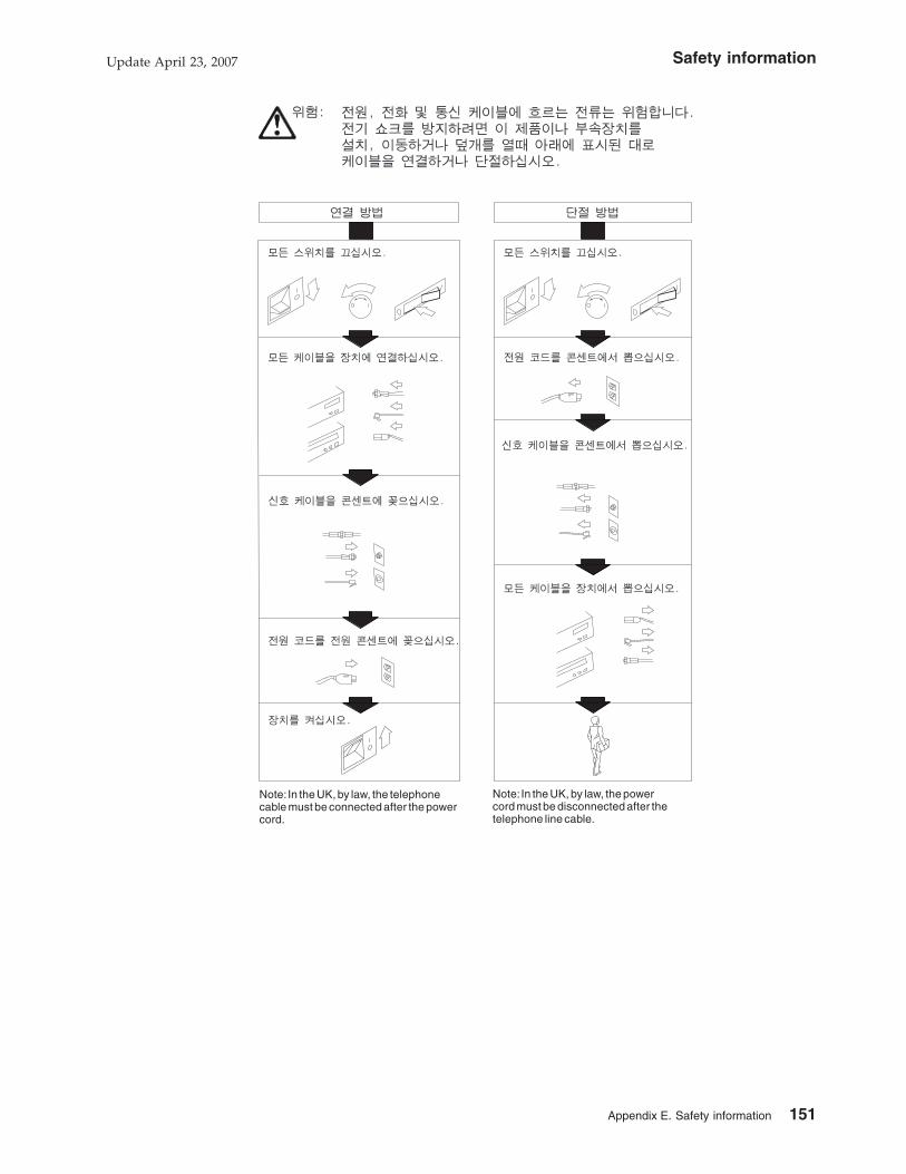
Note: In the UK, by law, the powercord must be disconnected after thetelephone line cable.
Note: In the UK, by law, the telephonecable must be connected after the powercord.
Safety informationUpdate April 23, 2007
Appendix E. Safety information 151
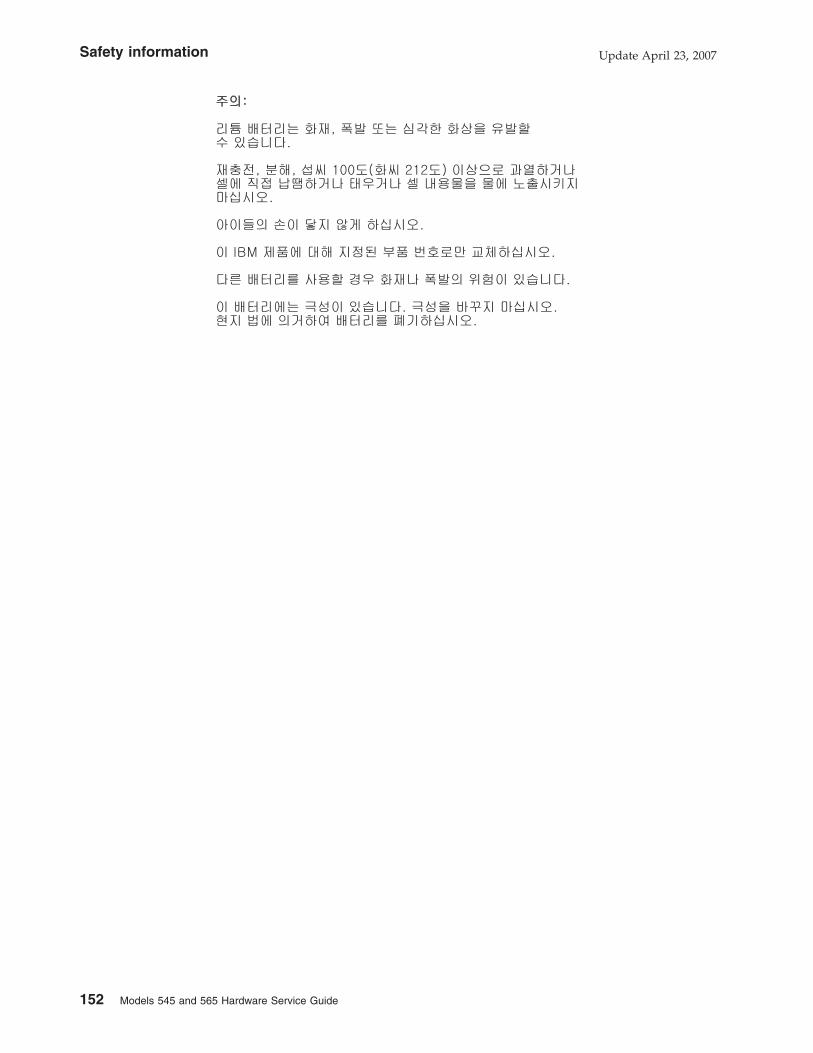
Safety information Update April 23, 2007
152 Models 545 and 565 Hardware Service Guide
Safety Information-Italian
Safety informationUpdate April 23, 2007
Appendix E. Safety information 153

Spegnere tutte le unita' (OFF).
Scollegare il cavo dialimentazione dalla presa.
Accendere tutte le unita' (ON).
Spegnere tutte le unita' (OFF).
Collegare il cavo di alimentazionealla presa.
Collegare i cavi segnali alle unita'.
Collegare i cavi segnali airispettivi connettori.
Scollegare i cavi segnalidalle prese.
Scollegare i cavi segnali dalleunita'.
La corrente elettrica di alimentazione deltelefono e dei cavi di comunicazione e'pericolosa. Per evitare scosse elettrichecollegare e scollegare i cavi, nella sequenzamostrata in figura, quando si installa, sitrasporta o si tolgono i coperchi di questoprodotto o delle unita' ad esso collegate.Non maneggiare i cavi di interconnessionedurante temporali.
Attenzione:
Una batteria al litio può incendiarsi, esplodere o causare ustioni. Non ricaricarla,
non smontarla, non riscaldarla ad una temperatura superiore a 100° C, non
saldarla, non incenerirla, non gettarla in acqua.
Tenere la batteria lontano dalla portata dei bambini.
Sostituirla soltanto con una batteria contrassegnata dal numero parte specifico per
questo prodotto IBM. L’utilizzo di un altro tipo di batteria può determinare rischi di
incendio o di esplosione. Il connettore della batteria è polarizzata; non tentare di
invertire la polarità.
Safety information Update April 23, 2007
154 Models 545 and 565 Hardware Service Guide

Smaltire la batteria secondo la normativa in vigore (D.Lgs. 22 del 5/2/97) e
successive disposizioni nazionali e disposizioni locali.
Safety informationUpdate April 23, 2007
Appendix E. Safety information 155

Safety Information-Spanish
Safety information Update April 23, 2007
156 Models 545 and 565 Hardware Service Guide

Primero, quite el cable de latoma de alimentación.
Encienda el dispositivo.
La corriente eléctrica de la alimentación,teléfono y cables de comunicación es peligrosa.Para evitar peligro de descargas cuando instale,mueva o abra las cubiertas de este producto ode un disp. conectado, conecte y desconectelos cables tal como se muestra a continuación.
Apague Todo.
Quite todos los cables de losdispositivos.
Conecte el cable de alimentacióna la toma de alimentación.
Primero, conecte todos los cablesa los dispositivos.
Apague Todo.
Conecte los cables de señala los receptáculos.
Quite los cables de señal delos receptáculos.
Precaución:
Una batería de litio puede causar un incendio, una explosión o quemaduras graves.
No recargar, desmontar, calentar por encima de los 100 grados C (212 grados F),
soldar directamente a la pila, incinerar o mojar el contenido de la pila.
Manténgala alejada de los niños.
Sustitúyala sólo con el número de pieza que se especifica para este producto IBM.
El uso de una batería distinta puede causar riesgos de incendio o explosión. El
conector de batería está polarizado; no intente invertir la polaridad.
Deseche la batería se acuerdo con la normativa local.
Safety informationUpdate April 23, 2007
Appendix E. Safety information 157

Safety Information-German
VORSICHT
Um gefährliche Spannungen zu vermeiden, dürfen während eines Gewitters
an diesem Gerät keine Kabel angeschlossen oder gelöst werden, ferner keine
Installation, Wartung oder Rekonfiguration durchgeführt werden.
VORSICHT
Aus Sicherheitsgründen
v darf das Netzkabel nur an eine Schutzkontaktsteckdose angeschlossen
werden.
v dürfen für den Anschluβ anderer Geräte an den Drucker auch nur
Schutzkontaktsteckdosen verwendet werden.
VORSICHT
Die Signalkabel nach Möglichkeit mit einer Hand anschlieβen oder lösen, um
gefährliche Körperströme zu vermeiden, die bei Berühren zweier Flächen mit
möglicherweise unterschiedlichen elektrischen Potentialen auftreten können.
Safety information Update April 23, 2007
158 Models 545 and 565 Hardware Service Guide

Achtung:
Lithiumbatterien sind feuergefährlich, explosiv und können schwere Verbrennungen
verursachen. Batterie nicht wiederaufladen, öffnen oder über 100 Grad Celsius
erhitzen; die Zelle nicht direkt anlöten, verbrennen oder den Inhalt der Zelle mit
Wasser in Berührung bringen.
Batterie nicht in Reichweite von Kindern aufbewahren.
Eine verbrauchte Batterie nur durch eine Batterie mit der für dieses IBM Produkt
spezifizierten Teilenummer ersetzen. Andere Batterien können sich entzünden oder
explodieren. Der Batterieanschluß hat zwei verschiedene Pole; beim Anschließen
die Pole nicht vertauschen.
Batterie gemäß den örtlichen Richtlinien für Sondermüll entsorgen.
Safety informationUpdate April 23, 2007
Appendix E. Safety information 159

Safety Information-Traditional Chinese
Safety information Update April 23, 2007
160 Models 545 and 565 Hardware Service Guide

Safety informationUpdate April 23, 2007
Appendix E. Safety information 161

Safety information Update April 23, 2007
162 Models 545 and 565 Hardware Service Guide

Glossary
This glossary includes terms and definitions from:
v American National Standard Dictionary for
Information Systems, ANSI X3.172-1990,
copyright 1990 by the American National
Standards Institute (ANSI). Copies may be
purchased from the American National
Standards Institute, 11 West 42nd Street, New
York, New York 10036. Definitions are identified
by the symbol (A) after the definition.
v The Information Technology Vocabulary,
developed by Subcommittee 1, Joint Technical
Committee 1, of the International Organization
for Standardization and the International
Electrotechnical Commission (ISO/IEC
JTC1/SC1). Definitions of published parts of this
vocabulary are identified by the symbol (I) after
the definition; definitions taken from draft
international standards, committee drafts, and
working papers being developed by ISO/IEC
JTC1/SC1 are identified by the symbol (T) after
the definition, indicating that final agreement
has not yet been reached among the
participating National Bodies of SC1.
A
active. (1) Able to communicate on the network. A
token-ring network adapter is active if it is able to
transmit and receive on the network (2) Operational. (3)
Pertaining to a node or device that is connected or is
available for connection to another node or device. (4)
Currently transmitting or receiving.
adapter. (1) In the point-of-sale terminal, a circuit card
that, with its associated software, enables the terminal
to use a function or feature. (2) In a LAN, within a
communicating device, a circuit card that, with its
associated software and/or microcode, enables the
device to communicate over the network.
address. (1) In data communication, the
IEEE-assigned unique code or the unique locally
administered code assigned to each device or
workstation connected to a network. (2) A character or
group of characters that identifies a register, a particular
part of storage, or some other data source or
destination. (A) (3) To refer to a device or an item of
data by its address. (I) (A) (4) The location in the
storage of a computer where data is stored.
addressing. (1) The assignment of addresses to the
instructions of a program. (2) In data communication,
the way in which a station selects the station to which it
is to send data.
alphanumeric. Pertaining to data consisting of letters,
digits, and usually other characters, such as punctuation
marks. (T) (A)
analog. (1) Pertaining to data consisting of
continuously variable physical quantities. (A) (2)
Contrast with digital.
application. (1) A collection of one or more programs
that work together to accomplish goals for a business.
(2) A set of executable files and data files required to
perform a desired function, which can consist of multiple
programs running on different workstations.
architecture. A logical structure that encompasses
operating principles including services, functions, and
protocols. See network architecture.
attach. (1) To connect a device physically. (2) To make
a device a part of a network logically. Compare with
connect.
attaching device. Any device that is physically
connected to a network and can communicate over the
network.
B
bit. Either of the digits 0 or 1 when used in the binary
numeration system. Synonymous with binary digit. (T)
bus. (1) In a processor, a physical facility on which
data is transferred to all destinations, but from which
only addressed destinations may read in accordance
with appropriate conventions. (2) A network
configuration in which nodes are interconnected through
a bidirectional transmission medium. (3) One or more
conductors used for transmitting signals or power. (A)
C
cash drawer. An optional I/O device attached to a
point-of-sale terminal. The cash drawer contains a till.
The cash drawer will open upon receiving a command.
See till.
CPU. The central processing unit of a computer.
circuit. (1) A logic device. (2) One or more conductors
through which an electric current can flow.
cluster. (1) A station that consists of a control unit (a
cluster controller) and the terminals attached to it. (2) A
group of APPN nodes that have the same network ID
and the same topology database. A cluster is a subset
of a NETID subnetwork. (3) In high-availability cluster
multiprocessing (HACMP), a set of iindependent
systems (called nodes) that are organized into a
Update April 23, 2007
© Copyright IBM Corp. 2006, 2007 163

network for the purpose of sharing resources and
communicating with each other.
collision. (1) An unwanted condition that results from
concurrent transmissions on a channel. (T) (2) When a
frame from a transmitting adapter encounters any other
signal in its path (frame, noise, or another type of
signal), the adapter stops transmitting and a collision is
registered.
command. (1) A request for performance of an
operation or execution of a program. (2) A character
string from a source external to a system that
represents a request for system action.
component. (1) Any part of a network other than an
attaching device, such as an IBM 8228 Multistation
Access Unit. (2) Hardware or software that is part of a
functional unit.
configuration. (1) The devices and programs that
make up a system, subsystem, or network. (A) See also
system configuration. (2) In the IBM StorePlace
Distributed Data Services for OS/2, program options
that are initially set at installation, and that can be
changed later. Changing these options requires an IPL.
These changes must be performed by a programmer or
store operations personnel. These options are used to
tune the product’s use of the operating system and
machine resources.
connect. In a LAN, to physically join a cable from a
station to an access unit or network connection point.
Contrast with attach.
controller. A unit that controls input/output operations
for one or more devices.
cursor. A movable point of light (or a short line) that
indicates where the next character is to be entered on
the display screen.
D
data. (1) A representation of facts, concepts, or
instructions in a formalized manner suitable for
communication, interpretation, or processing by human
or automatic means. (I) (A) (2) Any representations such
as characters or analog quantities to which meaning is
or might be assigned. (A)
data file. A collection of related data records organized
in a specific manner; for example, a payroll file (one
record for each employee, showing such information as
rate of pay and deductions) or an inventory file (one
record for each inventory item, showing such
information as cost, selling price, and number in stock.)
See also data set, file.
data processing system. A system, including
computer systems and associated personnel, that
performs input, processing, storage, output, and control
functions to accomplish a sequence of operations on
data. (A) (I)
data set. Logically related records treated as a single
unit. See also file.
DBCS. See double-byte character set.
device. (1) A mechanical, electrical, or electronic
contrivance with a specific purpose. (2) An input/output
unit such as a terminal, display, or printer. See also
attaching device.
diagnostic diskette. A diskette containing diagnostic
modules or tests used by computer users and service
personnel to diagnose hardware problems.
diagnostics. Modules or tests used by computer users
and service personnel to diagnose hardware problems.
digital. (1) Pertaining to data in the form of digits. (A)
Contrast with analog. (2) Pertaining to data consisting of
numerical values or discrete units.
DIP switch. A two-position switch on a circuit board
that is preset to control certain functions. The user can
change the position of a DIP switch to satisfy special
requirements.
disk. A round, flat, data medium that is rotated in order
to read or write data. (T) See also diskette, hard-disk
drive.
disk operating system (DOS). A computer operating
system that can perform only one task at a time.
diskette. A thin, flexible magnetic disk permanently
enclosed in a protective jacket. A diskette is used to
store information for processing.
diskette drive. The mechanism used to seek, read,
and write data on diskettes.
display. (1) A visual presentation of data. (2) A device
that presents visual information to the point-of-sale
terminal operator and to the customer.
distributed. Physically separate but connected by
cables.
DOS. See disk operating system.
double-byte character set (DBCS). A set of
characters in which each character is represented by 2
bytes. Languages such as Japanese, Chinese, and
Korean, which contain more symbols than can be
represented by 256 code points, require double-byte
character sets. Because each character requires 2
bytes, the typing, display, and printing of DBCS
characters requires hardware and programs that support
DBCS. Contrast with single-byte character set.
DRAM. Dynamic RAM. See RAM.
Update April 23, 2007
164 Models 545 and 565 Hardware Service Guide

driver. A software component that controls a device.
dump. (1) To record, at a particular instant, the
contents of all or part of one storage device in another
storage device. Dumping is usually for the purpose of
debugging. (T) (2) Data that has been dumped. (T)
DVD-ROM. Digital-video-disk read-only memory.
E
error message. A message that is issued because an
error has been detected.
F
FCC. See Federal Communications Commission.
feature. A part of an IBM product that may be ordered
separately by the customer.
Federal Communications Commission (FCC). A
board of commissioners appointed by the President
under the Communications Act of 1934, having the
power to regulate all interstate and foreign
communications by wire and radio originating in the
United States.
field. On a data medium or a storage medium, a
specified area used for a particular category of data; for
example, a group of character positions used to enter or
display wage rates on a panel. (T)
file. A named set of records stored or processed as a
unit. (T) For example, an invoice may form a record and
the complete set of such records may form a file. See
also data set.
.
FSB. Another name for the system bus. The system
bus is also called the frontside bus, memory bus, local
bus, or host bus.
flash memory. A data-storage device that is
programmable, erasable, and does not require
continuous power. The chief benefit of flash memory
over other programmable and erasable data storage
devices is that it can be reprogrammed without being
removed from the circuit board.
formatted diskette. A diskette on which track and
sector control information has been written and that can
be used by the computer to store data. Note: A diskette
must be formatted before it can receive data.
frame . (1) The unit of transmission in some LANs,
including the IBM Token-Ring Network and the IBM PC
Network. It includes delimiters, control characters,
information, and checking characters. On a token-ring
network, a frame is created from a token when the
token has data appended to it. On a token-bus network
(IBM PC Network), all frames including the token frame
contain a preamble, start delimiter, control address,
optional data and checking characters, end delimiter,
and are followed by a minimum silence period. (2) A
housing for machine elements. (3) In synchronous data
link control (SDLC), the vehicle for every command,
every response, and all information that is transmitted
using SDLC procedures. Each frame begins and ends
with a flag.
function. (1) A specific purpose of an entity, or its
characteristic action. (A) (2) In data communications, a
machine action such as a carriage return or line feed.
(A)
G
Ghz. The abbreviation for gigahertz. One GHz
represents 1 billion cycles per second. The speed of
microprocessors, called the clock speed, often is
measured in gigahertz.
H
hard-disk drive. In a personal computer system unit,
a disk storage device that reads and writes on rigid
magnetic disks. It is faster and has a larger storage
capacity than a diskette and is permanently installed.
Synonymous with fixed disk.
HID. See human interface devices.
hot pluggable. Refers to a hardware component that
can be installed or removed without disturbing the
operation of any other resource that is not connected to,
or dependent on, this component.
human interface devices (HID). Devices which allow
humans to interact and communicate with a computer.
Examples are a keyboard or a mouse.
hot plugging. Process of installing connections to the
serial bus while the system is running and without
powering down.
hot unplugging. Process of removing connections
from the serial bus while the system is running and
without powering down.
hypertext. (1) A method of presenting text in discrete
units, or nodes, that are connected by links for
navigation. (2) Text designed to be read or accessed in
a nonlinear manner using nodes that are connected by
links for navigation.
I
I/O. See input/output.
Update April 23, 2007
Glossary 165

I/O device. A device in a data processing system by
means of which data can be entered into the system,
received from the system, or both. (I) (A)
IBM Disk Operating System (DOS) . A disk operating
system based on MS-DOS that operates with all
IBM-compatible personal computers.
IEEE. Institute of Electrical and Electronics Engineers.
input/output (I/O). (1) Pertaining to a device whose
parts can perform an input process and an output
process at the same time. (I) (2) Pertaining to a
functional unit or channel involved in an input process,
output process, or both, concurrently or not, and to the
data involved in such a process.
integrated. Arranged together as one unit.
interference. (1) The prevention of clear reception of
broadcast signals. (2) The distorted portion of a
received signal.
interrupt. (1) A suspension of a process, such as
execution of a computer program, caused by an
external event and performed in such a way that the
process can be resumed. (A) (2) To stop a process in
such a way that it can be resumed. (3) A means of
passing processing control from one software or
microcode module or routine to another, or of requesting
a particular software, microcode, or hardware function.
J
jabber. Transmission by a data station beyond the
time interval allowed by the protocol. (T)
K
K. When referring to storage capacity, a symbol that
represents two to the tenth power, or 1024.
keyboard. A group of numeric keys, alphabetic keys,
special character keys, or function keys used for
entering information into the terminal and into the
system.
L
LAN. See local area network.
LAN adapter. The circuit card within a communicating
device (such as a personal computer) that, together with
its associated software, enables the device to be
attached to a LAN.
LED. Light-emitting diode.
light-emitting diode (LED). A semiconductor chip that
gives off visible or infared light when activated.
line. On a terminal, one or more characters entered
before a return to the first printing or display position.
link. (1) The logical connection between nodes
including the end-to-end link control procedures. (2) The
combination of physical media, protocols, and
programming that connects devices on a network. (3) In
computer programming, the part of a program, in some
cases a single instruction or an address, that passes
control and parameters between separate portions of
the computer program. (4) To interconnect items of data
or portions of one or more computer programs. (5) In
SNA, the combination of the link connection and link
stations joining network nodes. See also link
connection. Note: A link connection is the physical
medium of transmission; for example, a telephone wire
or a microwave beam. A link includes the physical
medium of transmission, the protocol, and associated
devices and programming; it is both logical and
physical.
link connection. (1) All physical components and
protocol machines that lie between the communicating
link stations of a link. The link connection may include a
switched or leased physical data circuit, a LAN, or an
X.25 virtual circuit. (2) In SNA, the physical equipment
providing two-way communication and error correction
and detection between one link station and one or more
other link stations. (3) In the IBM Store System, the
logical link providing two-way communication of data
from one network node to one or more other network
nodes.
load. In computer programming, to enter data into
memory or working registers.
local area network (LAN). A computer network
located on a user’s premises within a limited
geographical area. Note: Communication within a LAN
is not subject to external regulations; however,
communication across the LAN boundary may be
subject to some form of regulation.
logon. The procedure for starting up a point-of-sale
terminal or store controller for normal sales operations
by sequentially entering the correct security number and
transaction number. Synonymous with sign-on.
M
magnetic ink character reader (MICR). An input unit
that reads characters by magnetic ink character
recognition. (A)
magnetic ink character recognition. (1) MICR.
Character recognition of magnetic ink characters. (T) (2)
The identification of characters through the use of
magnetic ink.
MB. See megabyte.
Mbps. One million bits per second.
Update April 23, 2007
166 Models 545 and 565 Hardware Service Guide

megabyte (MB) . A unit of measure for data. 1
megabyte = 1 048 576 bytes.
memory. Program-addressable storage from which
instructions and other data can be loaded directly into
registers for subsequent execution or processing.
memory key. A USB removable storage device.
message. (1) An arbitrary amount of information
whose beginning and end are defined or implied. (2) A
group of characters and control bit sequences
transferred as an entity. (3) In telecommunication, a
combination of characters and symbols transmitted from
one point to another. (4) A logical partition of the user
device’s data stream to and from the adapter. See also
error message, operator message.
MICR. See magnetic ink character reader and
magnetic ink character recognition.
modular flash drive. A small, portable flash memory
card that plugs into a computer’s USB port and
functions as a portable hard drive. USB flash drives are
small enough to be carried in a pocket and can plug
into any computer with a USB drive. USB flash drives
have less storage capacity than an external hard drive,
but are smaller and more durable because they do not
contain any internal moving parts.
module. A program unit that is discrete and identifiable
with respect to compiling, combining with other units,
and load; for example, the input to, or output from, an
assembler, compiler, linkage editor, or executive routine.
N
network. (1) A configuration of data processing
devices and software connected for information
interchange. (2) An arrangement of nodes and
connecting branches. Connections are made between
data stations.
network architecture. The logical structure and
operating principles of a computer network. Note: The
operating principles of a network include those of
services, functions, and protocols.
noise. (1) A disturbance that affects a signal and that
can distort the information carried by the signal. (2)
Random variations of one or more characteristics of any
entity, such as voltage, current, or data. (3) Loosely, any
disturbance tending to interfere with normal operation of
a device or system.
nonvolatile random access memory (NVRAM) .
Random access memory that retains its contents after
electrical power is shut off. Contrast with volatile
memory.
NVRAM. See nonvolatile random access memory.
O
operating system. Software that controls the
execution of programs and that may provide services
such as resource allocation, scheduling, input/output
control, and data management. Although operating
systems are predominantly software, partial hardware
implementations are possible. (T)
Operating System/2® (OS/2®). A set of programs that
control the operation of high-speed large-memory IBM
Personal Computers providing multitasking. Contrast
with Disk Operating System (DOS).
operator. A person who operates a machine.
operator message. A message from the operating
system or a program telling the operator to perform a
specific function or informing the operator of a specific
condition within the system, such as an error condition.
option. (1) A specification in a statement, a selection
from a menu, or a setting of a switch, that can be used
to influence the execution of a program. (2) A hardware
or software function that can be selected or enabled as
part of a configuration process. (3) A piece of hardware
(such as a network adapter) that can be installed in a
device to modify or enhance device function.
OS. Operating system.
OS/2. Operating System/2.
P
page. The information displayed at the same time on
the screen of a display device.
panel. (1) A thin flat sheet, usually (a) of pressed
metal and carrying controls and indicators, (b) of glass,
or (c) of plastic. (2) A formatted display of information
that appears on a display screen.
parallel port. A port that transmits the bits of a byte in
parallel along the lines of the bus, one byte at a time, to
an I/O device. On a personal computer, it is used to
connect a device that uses a parallel interface, such as
a dot matrix printer, to the computer. Contrast with serial
port.
PC. See personal computer.
personal computer (PC). A desk-top, free-standing, or
portable microcomputer that usually consists of a
system unit, a display, a keyboard, one or more diskette
drives, internal fixed-disk storage, and an optional
printer. PCs are designed primarily to give independent
computing power to a single user and are inexpensively
priced for purchase by individuals or small businesses.
Examples include the various models of the IBM
Personal Computers.
Update April 23, 2007
Glossary 167

plug. (1) A connector for attaching wires from a device
to a cable, such as a store loop. A plug is inserted into
a receptacle or plug. (2) To insert a connector into a
receptacle or socket.
Plug and Play (PnP). Pertaining to the capability of a
hardware or software component to be installed on a
system with minimal effort and to be available for use
immediately thereafter.
PnP. See Plug and Play.
point-of-sale (POS). A method of providing
information to support sales and of collecting the
resulting sales information from retail devices located in
stores.
port. (1) An access point for data entry or exit. (2) A
connector on a device to which cables for other devices
such as display stations and printers are attached.
Synonymous with socket.
POS. See point-of-sale.
POST . Power-on self-test.
power-on self-test (POST) . A series of diagnostic
tests that are run automatically each time the
computer’s power is switched on.
problem determination. The process of determining
the source of a problem; for example, a program
component, machine failure, telecommunication
facilities, user or contractor-installed programs or
equipment, environmental failure such as a power loss,
or user error.
procedure. (1) A set of related control statements that
cause one or more programs to be performed. (2) A set
of instructions that gives a service representative a
step-by-step procedure for tracing a symptom to the
cause of failure.
processor. In a computer, a functional unit that
interprets and executes instructions. (A) (I)
protocol. (1) A set of semantic and syntactic rules that
determine the behavior of functional units in achieving
communication. (I) (2) A specification for the format and
relative timing of information exchanged between
communicating parties.
R
RAM. See random access memory.
random access memory (RAM). A computer’s or
adapter’s volatile memory, which can be accessed
nonsequentially.
read. To acquire or to interpret data from a storage
device, from a data medium, or from another source. (I)
(A)
real-time. (1) Pertaining to the actual time during
which a physical process occurs. (2) Pertaining to data
collected concurrently with physical events, so that the
results of the collection operation may be used to
influence the sequence of events.
receive. To obtain and store information transmitted
from a device.
record. A collection of related items of data, treated as
a unit; for example, in stock control, each invoice could
constitute one record. A complete set of such records
may form a file.
repeater. A device that amplifies or regenerates data
signals in order to extend the range of transmission
between devices in a network.
S
SBCS. See single-byte character set.
scanner. A device that examines the bar code on
merchandise tickets, credit cards, and employee badges
and generates analog or digital signals corresponding to
the bar code.
serial port. On personal computers, a port used to
attach devices such as display devices, letter-quality
printers, modems, plotters, and pointing devices such as
light pens and mice; it transmits data one bit at a time.
Contrast with parallel port.
signal. A variation of a physical attribute, used to
convey data. (A)
single-byte character set (SBCS). Single-byte
character set. A character set in which each character is
represented by a one-byte code. Contrast with
double-byte character set.
socket. (1) An opening that holds something. (2)
Synonym for port.
source. The origin of any data involved in a data
transfer.
subsystem. A secondary or subordinate system,
usually capable of operating independently of, or
asynchronously with, a controlling system. (T)
switch. (1) A device for making and breaking electrical
connections, for making a selection, or for requesting a
function or operation. (2) On an adapter, a mechanism
used to select a value for, enable, or disable a
configurable option or feature.
system. (1) In data processing, a collection of people,
machines, and methods organized to accomplish a set
of specific functions. (I) (A) See also data processing
system, operating system, and system unit. (2) In the
IBM StorePlace Distributed Data Services for OS/2, a
group of nodes for which files are managed.
Update April 23, 2007
168 Models 545 and 565 Hardware Service Guide

system board. In a system unit, the main circuit board
that supports a variety of basic system devices, such as
a keyboard or a mouse, and provides other basic
system functions.
system bus. The unit that connects the CPU to the
main memory on the system board.
system configuration. A process that specifies the
devices and programs that form a particular data
processing system.
system unit. (1) A part of a computer that contains the
processing unit and may contain devices such as disk
and diskette drives. (2) In an IBM Personal Computer,
the unit that contains the processor circuitry, read-only
memory (ROM), random access memory (RAM), and
the I/O channel. It may have one or more disk or
diskette drives. (3) In an IBM Store System terminal, the
part of the terminal that contains the processing unit,
ROM, RAM, disk and diskette drives, and the I/O
channel.
T
terminal. In data communication, a device, usually
equipped with a keyboard and a display, that is capable
of sending and receiving information.
till. A tray in the cash drawer of the point-of-sale
terminal, used to keep the different denominations of
bills and coins separated and easily accessible.
transmit. To send information from one place for
reception elsewhere. (A)
twisted pair. A transmission medium that consists of
two insulated electrical conductors twisted together. (A)
typematic. The ability of a key on a keyboard to
repeatedly type a character as long as it is held down.
U
Universal Serial Bus (USB). A serial interface
standard for telephony and multimedia connections to
personal computers.
Universal Serial Bus (USB), powered. A
powered-USB connector provides additional power from
the host system. A powered-USB receptacle consists of
two connectors stacked vertically inside the common
housing. The upper connector contains four contacts
that are used for powering the attached device.
unshielded twisted pair (UTP). One or more twisted
pairs of copper wire in the unshielded voice-grade cable
commonly used to connect a telephone to its wall jack.
user. (1) A category of identification defined for file
access protection. (2) A person using a program or
system.
USB. See Universal Serial Bus.
V
version . A separately licensed program that usually
has significant new code or new function.
vital product data (VPD). Information about the
computer, such as machine type and model or serial
number, stored in the BIOS.
volatile memory. Memory that loses its contents when
power is turned off.
VPD. See vital product data.
Update April 23, 2007
Glossary 169
||||

Update April 23, 2007
170 Models 545 and 565 Hardware Service Guide

Part number index
Part
Number
Asm–
Index Page
12X1000 1–2 101
12X1001 1–2 101
12X1002 1–2 101
12X1009 1–23 101
12X1036 1–6 101
12X1110 1–24 101
12X1129 4–6 109
12X1129 5–6 111
14R0157 2–5 105
20P0308 5–5 111
39X8908 1–22 101
40N5755 1–17 101
41A3641 1– 101
41D0171 1– 101
41D0210 5–1 111
41D0211 4–2 109
41D0211 5–2 111
41D0212 4– 109
41D0214 2–1 105
41D0216 2– 105
41D0261 4–1 109
41D9746 1– 102
41P0212 5– 111
42N5755 3–2 107
42V3682 1–28 101
42V3886 1–1 101
42V3887 1–1 101
42V3888 1–1 101
42V3889 1–3 101
42V3890 1–3 101
42V3891 1–3 101
42V3892 1–6 101
42V3893 1–5 101
42V3894 1–5 101
42V3895 1–5 101
42V3897 1–4 101
42V3922 1–10 101
42V3923 1–10 101
42V3924 1–7 101
42V3925 1–9 101
42V3926 1–9 101
42V3927 1–11 101
42V3928 1–11 101
42V3930 1–16 101
42V3931 1–13 101
42V3932 1–26 101
42V3933 1–27 101
42V3935 1–25 101
42V3936 1–19 101
42V3937 1–8 101
Part
Number
Asm–
Index Page
42V3938 1–21 101
42V3939 1– 101
42V3940 1–29 101
42V3941 1–29 101
42V3943 1–12 101
42V3944 1– 101
42V3945 1–18 101
42V3946 1–18 101
42V3947 1– 101
42V3948 1–20 101
42V3949 1–20 101
42V3950 1–14 101
42V3951 1– 101
42V3952 1– 102
42V3953 1–15 101
42V3956 1– 102
42V3957 1– 102
42V3958 3–3 107
42V3959 3–4 107
42V3960 3–1 107
42V3961 3–1 107
42V3964 2–2 105
42V3965 2–3 105
42V3966 4–3 109
42V3966 5–3 111
42V3967 4–4 109
42V3967 5–4 111
42V3969 1– 101
42V3980 1– 101
45P6222 1– 101
47P9273 2–4 105
Update April 23, 2007
© Copyright IBM Corp. 2006, 2007 171

Update April 23, 2007
172 Models 545 and 565 Hardware Service Guide

Index
Special characters 102
Numerics12-inch display dimensions 118
15-inch display dimensions 119
15-pin serial portconnector pin assignments 127
17-inch display dimensions 120
4610 SureMark printer, installing 95
Aabout this guide xix
accessibility of publications xix
adapter cable, RJ-45 to 9-pin conversion 29
advanced BIOS window 14
altitude limits 130
audience xix
Australia new Zealand 134
Avis de conformité aux normes d’Industrie
Canada 133
Bbase plate, removing and replacing 58
base-foot countertop mountingmounting the system 71
batteriesdisposal xvii
battery, system board 52
BIOSflashing procedure 17
repairing 18
update 18
blank, PC card 60
board 50
CCanadian emission compliance 133
cash drawermounting 79
troubleshooting 20
Cash drawerconnector pin assignments 129
cash drawer, countertop and full-size 84
checklist, problem diagnosis 19
Chinese Class A warning statement 135
clearingCMOS settings 15
system password 15
clock, real-time 16
CMOSclearing 15
CMOS (continued)recovery 23
settingsrestoring defaults 15
standard features 14
CMOS setup utilityconfiguring the COM ports 16
CMOS Setup UtilityAdvanced BIOS Features 14
main window 13
starting the 13
compatible products 11
configuration, main window 13
configuringI/O devices 14
power savings 14
configuring the COM ports 16
connector15-pin serial pin assignments 127
cash drawer pin assignments 129
Ethernet pin assignments 127
external video pin assignments 128
headphone pin assignments 125
integrated customer display pin assignments 129
keyboard pin assignments 124
microphone pin assignments 125
MSR pin assignments 122
Universal Serial Bus (USB) pin assignments 124
connector pin assignments 125
connector pin, assignments 122
connectorsspeaker pin assignments 122
connectors, power, and brightness controls 5
countertopintegration tray legend 77
integration tray mounting 74
mounting the system 69
countertop and full-size cash drawer 84
countertop mount 71
customer display, integrated 66
Ddamage from electrostatic discharge 136
default CMOS settingsclearing 15
restoring 15
diagnosing problemspreliminary checklist 19
diagnosing problems and troubleshooting 19
dimensions 115, 118
displayremoving and replacing 35
display restrictions 8
Display tablet 35
disposal of equipment xvii
disposing of used products xvii
Update April 23, 2007
© Copyright IBM Corp. 2006, 2007 173

distributed character display and APA display, mounting
to a cash drawer 93
documentation, related xix
drawer, countertop and full-size cash 84
Driver for Windows, IBM UPOS 7
dual video adapter 63
EEAS xviii
electronic article surveillance xviii
electronic article surveillance device xviii
electronic emissions 133
electrostatic discharge (ESD) 136
end of life disposal xvii
environmentalnotices xvii
statements xvii
equipment disposal xvii
Ethernetconnector pin assignments 127
EU 133
European conformity statement 133
external connectors 122
external video, connector pin assignments 128
FFCC statement 133
featuressystem management 9
features, optional 4
field replaceable units 99
filler panels without a printer, installing 79
flash bios 18
flash BIOS update procedure 17
power interruption 18
flash drive 67
flash, update 18
FRU 99
FRU cataloghow to use 99
full-size cash drawer, countertop and 84
Hhandling static-sensitive devices xviii, 28
headphoneconnector pin assignments 125
heatsink assembly 54
height 115
humidity limits 130
IIBM UPOS Drivers for Windows 7
industry standard devices 9
information, task 19
installation procedures 93
installing additional peripheral devices 93
installing filler panels without a printer 79
installing the 4610 printer onto the integration tray 89
installing the keyboard-integration tray on a cash
drawer 87
Integrated customer displayconnector pin assignments 129
integration tray, keyboard, mounting 84
integration tray, non-keyboard 74
JJapanese power line harmonics compliance
statement 134
Japanese Voluntary Control Council for Interference
(VCCI) Statement 134
jumper locations, system board 52
Kkeyboard 125
connector pin assignments 124
troubleshooting 22
keyboard connector 124
keyboard-integration tray mounting 84
knowledgebase 19
Korean Communications Statement 135
LLoad defaults 15
Mmagnetic stripe reader xviii
connector pin assignments 122
main window, configuration 13
management features, system 9
management programs, system 9
memory keys, supported 17
memory modulesremoving and replacing 56
memory modules and industry standards 57
mercury-added statement xviii
microphoneconnector pin assignments 125
model number location 11
Models 545 and 565connectors, power, and brightness controls 5
features and models summary 2
models and features 2
Models E45 and E65 3
Models P45 and P65 3
modular flash drive 67
modular service tools 29
mountingbase plate to a countertop 71
configurations 69
Countertop and full-size cash drawe 84
countertop integration tray mounting 74
non-keyboard-integration tray 74
Update April 23, 2007
174 Models 545 and 565 Hardware Service Guide

mounting the integration tray to a countertop 84
mounting the SurePOS 500 69
mouse connector 125
MSR xviii
removing and replacing 59
troubleshooting 21
MSR location xviii
Nnon-keyboard-integration tray
mounting the system 74
notices 131
environmental xi
safety xi
safety translation xi
notices, electronic emissions 133
Oopening the I/O tailgate cover 32
operating system and display restrictions 8
operating systems 7
operating systems supported 7
operating systems, understanding the supported video
resolutions and 7
optional features 4, 59
optional memory 67
Ppart numbers
integration tray keyboard, cash drawer and
countertop 104
integration tray non-keyboard, countertop 108
integration turn on— keyboard, cash drawer 110
Models 545 and 565 101
optional peripherals 107
power cords 113
parts catalog 19, 99
passwordclearing 15
setting 15
PC card adapterremoving and replacing 61
PC health status 15
peripheral devices 93
4610 SureMark Models TF6 or TF7 printers 95
installing 93
pictorial overview of removal and replacements 26
pin assignments 122
Ethernet connector 127
planning information 115
PnP/PCI configurations option 14
power consumption 121
power cordspart numbers 113
power management window 14
power ratings, port 121
power requirements 121
power savingconfiguration 14
power supplyremoving and replacing 46
power supply latch armopening 47
power, connectors, and brightness controls 5
power, input voltage 121
printer installation, 4610 95
printer, installing filler panels without a 79
problem determination 13
problem diagnosispreliminary checklist 19
problem diagnosis, start 19
problem symptomsaudio is not working 22
blank screen 20
cash drawerdisplay status does not match action 21
does not open 20, 21
does not open correctly 21
does not open smoothly 21
does not stay closed 20
diskette drive does not work 22
keyboard does not work 22
MSR not reading 21
no power light on operator display tablet 20
no power light on tower unit 20
operator display backlight dark or dim 21
running fan 22
touch screen not working 21
processor fan 54
processor module 55
productdisposal xvii
products and services 131
products, compatible 11
publications xix
related xix
website xix
Rradio interference 134
real-time clock and CMOS 16
rear cover 31
recover from flash BIOS update error condition 18
recovery, CMOS 23
related publications xix
remote management 10
removal and replacement procedures 29, 35, 54, 59,
61
base plate 58
cable tie bar 45
covers 30
front cover 30
hinge cover 34
opening the I/O tailgate cover 32
rear cover 31
top cover 33
display tablet cable 36
Update April 23, 2007
Index 175

removal and replacement procedures (continued)front bezel and LCD assembly 37
HDD and HDD bracket 41
HDD cables 44
HDD fan and bracket 43
hinge assembly 40
memory modules 56
modular flash drive 67
operator card 39
optional featuresintegrated customer display 66
MSR 59
MSR hole plug 60
PC card blank 60
speaker 64
video adapter card 63
power supply 46
power supply latch arm 47
processor fan/heatsink assembly 55
processor module 55
rear connector panel (tailgate) 48
system board 50
system-board battery 52
tablet, display 35
removing and replacing FRUs 25
processor module 55
Repair 18
repairing the flash bios 18
replacing FRUs 25
requirementspower 121
researching the knowledgebase 19
resolutions and operating systems, understanding the
supported video 7
restoring default CMOS settings 15
restrictions, display 8
RJ-45connector pin assignments 126
RJ-45 connectors 125
running diagnostics and troubleshooting 13
Ssafety
laser xi
notice translations xi
notices xi
safety information xi, 137, 139
Safety Information English 139
safety notices 141
serial connectors 125
serial number location 11
serial number, location 14
service personnel tools 29
settingchanging, clearing password 15
clearing CMOS 15
restoring default CMOS 15
setup, how to enter 13
size of unit 118
skills needed to install, configure, and administer this
product xix
solid state hard file 67
speaker 64
speaker connector 122
speaker, connector pin assignments 122
specificationsheight 115
weight 115
standard interface 9
starting the CMOS Setup Utility 13
static-sensitive devices, handling xviii, 28
summary window, configuration 13
support xix
Supported devices 9
supported memory keys 17
supported video resolutions and operating systems,
Understanding the 7
system boardjumper locations 52
jumper settings 52
removing and replacing 50
system management features 9
system management programs 9
system specifications 115
system specs 115
Ttablet, removing and replacing 35
tailgate connectorremoving and replacing 48
tailgate cover, opening 32
Taiwan contact information 136
Taiwan recycle statement 136
Taiwanese Class A Warning Statement 135
tapping twice, touch screen 13
task information 19
temperature limits 130
TF6 and TF7 95
tools, service personnel 29
touch screentroubleshooting 21
touch screen, tapping twice 13
trademarks 137
tray dimensions 116
troubleshooting 20
preliminary checklist 19
Uunderstanding the supported video resolutions and
operating systems 7
universal serial bus (USB)connector pin assignments 124
update flash BIOS 17
UPOS Drivers for Windows, IBM 7
URL, support 16
USB antenna specification 4
usb port connectors 124
Update April 23, 2007
176 Models 545 and 565 Hardware Service Guide

Vvideo card
removing and replacing 63
video resolutions and operating systems, understanding
the supported 7
WWake on Ring 14
web siteIBM Retail Store Solutions 16
Web sites xix
weight 115
Update April 23, 2007
Index 177

Update April 23, 2007
178 Models 545 and 565 Hardware Service Guide

Readers’ comments—we would like to hear from you
SurePOS 500 Series
Hardware Service Guide for Models 545 and 565
Publication No. SY27-0423-01
We appreciate your comments about this publication. Please comment on specific errors or omissions, accuracy,
organization, subject matter, or completeness of this book. The comments you send should pertain to only the
information in this manual or product and the way in which the information is presented.
For technical questions and information about products and prices, please contact your IBM branch office, your IBM
business partner, or your authorized remarketer.
When you send comments to IBM, you grant IBM a nonexclusive right to use or distribute your comments in any
way it believes appropriate without incurring any obligation to you. IBM or any other organizations will only use the
personal information that you supply to contact you about the issues that you state on this form.
Comments:
Thank you for your support.
Submit your comments using one of these channels:
v Send your comments to the address on the reverse side of this form.
If you would like a response from IBM, please fill in the following information:
Name
Address
Company or Organization
Phone No. E-mail address

Readers’ Comments — We’d Like to Hear from You SY27-0423-01
SY27-0423-01
���
Cut or FoldAlong Line
Cut or FoldAlong Line
Fold and Tape Please do not staple Fold and Tape
Fold and Tape Please do not staple Fold and Tape
NO POSTAGENECESSARYIF MAILED IN THEUNITED STATES
BUSINESS REPLY MAIL FIRST-CLASS MAIL PERMIT NO. 40 ARMONK, NEW YORK
POSTAGE WILL BE PAID BY ADDRESSEE
IBM Corporation
Retail Store Solutions Information Development
Department ZBDA
IBM Corporation
P.O. Box 12195
Research Triangle Park, NC 27709-9990
_ _ _ _ _ _ _ _ _ _ _ _ _ _ _ _ _ _ _ _ _ _ _ _ _ _ _ _ _ _ _ _ _ _ _ _ _ _ _ _ _ _ _ _ _ _ _ _ _ _ _ _ _ _ _ _ _ _ _ _ _ _ _ _ _ _ _ _ _ _ _ _ _ _ _ _ _ _ _ _ _ _ _ _ _ _ _ _ _
_ _ _ _ _ _ _ _ _ _ _ _ _ _ _ _ _ _ _ _ _ _ _ _ _ _ _ _ _ _ _ _ _ _ _ _ _ _ _ _ _ _ _ _ _ _ _ _ _ _ _ _ _ _ _ _ _ _ _ _ _ _ _ _ _ _ _ _ _ _ _ _ _ _ _ _ _ _ _ _ _ _ _ _ _ _ _ _ _
__
__
__
__
__
__
__
__
__
__
__
__
__
__
__
__
__
__
__
__
__
__
__
__
__
__
__
__
__
__
__
__
__
__
__
__
__
__
__
__
__
__
__
__
__
__
__
__
__
_


���
Update April 23, 2007
SY27-0423-01