Embed Size (px)
Citation preview

PageSection - D7 - 64CForm 402167FEB - 2007
Models 1400, 1442, 1442E, 1444, 1444EPowerLuber Grease Gun
Series “B”
Patent Pending
Note: Extra battery only included on Models 1444 and 1444E

Page Number - 2
Models 1400, 1442, 1442E, 1444, 1444E PowerLuber Grease Gun
Form 402167
GENERAL SAFETY RULES - FOR ALL BATTERY OPERATED TOOLSWARNING! READ AND UNDERSTAND ALL INSTRUCTIONS.Failure to follow all instructions listed below, may result in electric shock, fire and/or serious personal injury.SAVE THESE INSTRUCTIONS.
Work AreaKeep your work area clean and well lit. Clut-tered benches and dark areas invite accidents.Do not operate power tools in explosive atmo-spheres, such as in the presence offlammable liquids, gases, or dust. Power tools create sparks which may ignite the dust or fumes.Keep bystanders, children, and visitors away while operating a power tool. Distractionscan cause you to lose control.
Electrical SafetyDo not abuse the cord. Never use the cord to carry the tool. Keep cord away from heat, oil, sharp edges, or moving parts. Replace damaged cords immediately. Damaged cords may create a fire. Applies only to tools with a separable battery pack.A battery operated tool with integral batteries or a separate battery pack must berecharged only with the specified charger for the battery. A charger that may be suitable for one type of battery may create a risk of fire when used with another battery.Use battery operated tool only with specifically designated battery pack. Use of any other bat-teries may create a risk of fire.
Personal SafetyStay alert, watch what you are doing, and use common sense when operating a powertool. Do not use tool while tired or under the influence of drugs, alcohol, or medication. A moment of inattention while operating power tools may result in serious personal injury.Dress properly. Do not wear loose clothing or jewelry. Contain long hair. Keep yourhair, clothing, and gloves away from moving parts. Loose clothes, jewelry, or long hair can be caught in moving parts.Avoid accidental starting. Be sure switch is in the locked or off position before insertingbattery pack. Carrying tools with your finger on the switch or inserting the battery pack into a tool with the switch on invites accidents.Remove adjusting keys or wrenches before turning the tool on. A wrench or a key that is left attached to a rotating part of the tool may result in personal injury.
Do not overreach. Keep proper footing and bal-ance at all times. Proper footing andbalance enable better control of the tool in unexpected situations.Use safety equipment. Always wear eye protec-tion. Dust mask, non-skid safety shoes,hard hat, or hearing protection must be used for appropriate conditions.
Tool Use and CareUse clamps or other practical way to secure and support the workpiece to a stableplatform. Holding the work by hand or against your body is unstable and may lead to loss of control.Do not force tool. Use the correct tool for your application. The correct tool will do the job bet-ter and safer at the rate for which it is designed.Do not use tool if switch does not turn it on or off. A tool that cannot be controlled with the switch is dangerous and must be repaired.Disconnect battery pack from tool or place the switch in the locked or off position before making any adjustments, changing accesso-ries, or storing the tool. Such preventive safety measures reduce the risk of starting the tool accidentally.Store idle tools out of reach of children and other untrained persons. Tools aredangerous in the hands of untrained users.When battery pack is not in use, keep it away from other metal objects like: paper clips, coins, keys, nails, screws, or other small metal objects that can make a connection from one terminal to another. Shorting the battery terminals together may cause sparks, burns, or a fire.Maintain tools with care. Keep cutting tools sharp and clean. Properly maintained toolswith sharp cutting edge are less likely to bind and are easier to control.Check for misalignment or binding of moving parts, breakage of parts, and any othercondition that may affect the tool’s operation. If damaged, have the tool serviced before using.Many accidents are caused by poorly main-tained tools.Use only accessories that are recommended by the manufacturer for your model.Accessories that may be suitable for one tool may create a risk of injury when used on another tool.
ServiceTool service must be performed only by quali-fied repair personnel. Service ormaintenance performed by unqualified person-nel may result in a risk of injury.

Page Number - 3
Models 1400, 1442, 1442E, 1444, 1444E PowerLuber Grease Gun
Form 402167
SafetyRead and carefully observe these operating instructions before unpacking and operating PowerLuber. Operate PowerLuber only after safety instructions and this operation manual are fully understood.
Never operate PowerLuber in explosive at-mosphere. Electric power tools can create sparks which may ignite flammable liquids, dust or fumes.Do not use battery charger in damp or wet locations.
SpecificationsBasic PowerLuber Model 1400Operating Power, Volt 14.4Maximum Operating Pressure, PSIG (bar) - Low Output - 7,000 (476) - High Output - 3,000 (204)Grease Reservoir Capacity, oz. (g) 14.5 (411)Operating Temperature Range, °F (°C) 0 to 120 (-18 to +50)Operating Current, Amp 4.0Lubricant (Grease) Up to NLGI #2Grease output oz./min. (gram/min) - Low Output (L) 3.8 (108) - High Output (H) 8.5 (241)Weight, Lbs. (Kg) 8.0 (3.6)Accessories: Battery NiCd Model 1401 Output, VDC 14.4 Capacity, mAh 1700Battery Charger Model 1410 Charge time 1 Hour Input, VAC (2.0 A) 120 V, 60 Hz Model 1410E (for use in Europe) Input, VAC, (1.0 A) 220 V, 50 HzOutlet Hose Model 1230 Pressure Rating, psi (Bar) 7,500 (510) Length of the Hose, In (mm) 30 (760)Hydraulic Coupler for grease fittingsCarying case model material: Polyeth-ylene
NOTE: Operating current and grease output data at 1,000 PSI (69 bar).
General DescriptionThe Lincoln PowerLuber is a fully battery operational, automatic grease gun. The gun was developed for manual lubrication of the grease points and includes a circuit breaker to stop motor at excessive pressure (7000 PSI or 476 Bar) in the case of a blocked bearing, fitting or lubrication line.
The PowerLuber is driven by a small, low voltage electric motor connected to a three-stage planetary gear transmission. The rotary motion of the motor is converted into a reciprocating motion of the plunger using a yoke mechanism. The PowerLuber is a posi-tive displacement single acting pump.
Grease gun can develop high pressure - up to 7,000 PSI (476 Bar). Use safety glasses and gloves for protection during operation. Keep hands clear of the exposed rubber portion of hose.
Extreme pressure may cause nozzle extension or whip hose to burst. Use only Lincoln APPROVED hoses and follow whip hose instructions and warnings.
Models and ComponentsSales Model Basic PowerLuber Battery Charger Case
1442 1400 1401 1410 14021442E 1400 1401 1410E 14021444 1400 1401(2) 1410 1402
1444E 1400 1401(2) 1410E 1402
When servicing a tool, use only identical replacement parts. Follow instructions in theMaintenance section of this manual. Use of unauthorized parts or failure to follow Mainte-nance Instructions may create a risk of shock or injury.
Appropriate useThe PowerLuber was exclusively designed to pump and dispense lubricant using 14.4 volt battery power.The maximum specification ratings should not be exceeded. Any other use not in accordance with instruc-tions will result in loss of claim for warranty or liability.
Page Number - 4
Models 1400, 1442, 1442E, 1444, 1444E PowerLuber Grease Gun
Form 402167
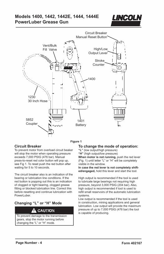
Figure 1
Circuit BreakerTo prevent motor from overload circuit beaker will stop the motor when operating pressure exceeds 7,000 PSIG (476 bar). Manual press-to-reset red color button will pop up, see Fig 1. To reset push the red button after waiting for 5 to 10 seconds.
The circuit breaker also is an indication of the bearing or lubrication line conditions. If the red button is popping out this is an indication of clogged or tight bearing, clogged grease fitting or blocked lubrication line. Correct this before resetting and continue lubrication with PowerLuber.
Changing “L” or “H” Mode
To change the mode of operation:“L” (low output/high pressure)“H” (high output/low pressure)When motor is not running, push the red lever (Fig. 1) until letter “L” or “H” will be completely visible in the window.In case the red lever is not completely shift-ed/engaged, hold this lever and start the tool.
High output is recommended if the tool is used to lubricate large bearings not requiring high pressure, beyond 3,000 PSIG (204 bar). Also, high output is recommended if tool is used to refill small reservoirs of the automatic lubrication systems. Low output is recommended if the tool is used in construction, mining applications and general lubrication. Low output will provide the maximum pressure of up to 7,000 PSIG (476 bar) the tool is capable of producing.
To prevent damage to the transmission gears, stop the motor running before changing the “L” or “H” mode.
Circuit Breaker Manual Reset Button
High/Low Output Lever
StrokeCounter
1400
1401Battery
123030 Inch Hose
5852 Coupler
Vent/Bulk Fill Valve

Page Number - 5
Models 1400, 1442, 1442E, 1444, 1444E PowerLuber Grease Gun
Form 402167
USE AND CARE1. Do not continue to hold down trigger if
grease gun is stalled. This could damage the motor or cause fire.
2. When battery pack is not in use, keep it away from other metal objects like: paper clips, coins, keys, nails, screws, or other small metal objects that can make a connection from one terminal to another. Shorting battery terminals together may cause sparks, burns, or a fire.
3. Use only accessories that are recom-mended for use with the Lincoln Power-Luber. This tool is a fully rated portable power lubrication product, only acces-sories that are capable of handling 7,000 psi (476 bar) should be used.
SERVICE1. Service must be performed only by qualified
repair personnel. Service or maintenance performed by unqualified personnel may result in a risk of injury.
2. When servicing a PowerLuber, use only Lin-coln replacement parts. Use of unauthorized parts may create risk of injury and will void the warranty.
INSPECTIONVisually inspect for damaged, loose or missing parts. If equipment is worn or damaged, remove from service. Contact an authorized service center for damage assessment or repair.
OPERATIONPrime the PowerLuber after each refill or grease cartridge change. Prime the gun before using it to lubricate grease points.
To prime, operate the gun until grease flows from the hose. Use vent valve (Figure 1, page 3) to expel air pockets.
Air pockets in the cartridge lubricant will cause the gun to lose its prime.
PERSONAL SAFETY1. Always wear eye protection. The Power-
Luber can generate up to 7,000 psi (476 bar).
2. Use only Lincoln 1218, 1224, 1230 or 1236 outlet whip hoses. Grease injection injuries are a very serious injury. Hold the hose only in the area of the spring guard.
3. Avoid accidental starting. Be sure switch is not depressed when inserting battery pack.
4. Do not bend the hose so that it becomes kinked.
5. Replace the hose at the first sign of wear, kink or damage to the outside jacket.
Stroke counterThe tool is equipped with capability for cali-bration. This is accomplished by measuring (weighing) grease flow output and dividing the weight of grease by number of strokes. Simply put your thumb on the stroke counter button, Fig. 1 during operation of the tool and count. Some OEM’s are recommending the exact amount of grease to lubricate critical bear-ings. By counting the strokes you will know how much grease has been dispensed to lubricate the bearing. Here is the table of the grease output vs. number of strokes.
Stroke count Output/stroke oz. gram 10 0.20 5.7 15 0.30 8.5 20 0.40 11.4
Note: Lincoln is recommending this feature only on low output/high pressure mode.
Removing Empty Grease Cartridge1. Pull back on the follower handle until the
follower rod is fully extended and latch the follower rod groove into the slot on the tube cap.
2. Unscrew the grease tube assembly from the PowerLuber.
3. Carefully release the follower handle to eject the empty cartridge from container tube.
Installing Grease Cartridge1. Visually check the follower seal lip direction
before loading a new cartridge. The follower seal lip must be directed toward the follower handle or rear side for cartridge loading. See Fig. 2. To change the direction of the follower seal, unscrew tube cap from grease tube assembly and pull on the handle to remove follower seal from tube. Flip follower seal over and re-assemble.
2. Pull back on the follower handle and latch the follower rod groove into the slot on the tube cap.
3. Remove the plastic cap from the grease car-tridge and insert cartridge into the container tube.

Page Number - 6
Models 1400, 1442, 1442E, 1444, 1444E PowerLuber Grease Gun
Form 402167
TO CONVERT GUN TO ALLOW FILLING FROM BULK CONTAINER OR FILLER PUMP1. Unscrew the grease tube assembly cap
from the grease tube assembly. Pull on the follower handle to extract the follower and spring from the grease tube assembly.
2. Grasp follower between thumb and forefin-ger and flip the follower lip from the rear to the front side.
NOTE. The follower resembles a cup. When the gun is assembled for use with bulk lubricant, the cup opens toward the pump assembly.3. Reassemble follower into grease tube
assembly and position with the follower handle so that the grease tube assembly cap can be tightened onto the container tube.
Slowly unscrew the grease tube assembly from the pump assembly until lubricant oozes from the interface. Tighten grease tube assembly into the pump assembly.
Figure 3
TO FILL THE GUN WITH A FILLER PUMPEngage the follower rod with the follower by rotating the follower handle. Insert the gun vent/bulk fill valve into the filler pump socket. Operate the filler pump to fill the container. When the follower rod groove is exposed, the grease tube assembly is filled. The follower rod will be extended approximately 8 inches (20 cm). Disengage the follower rod from the fol-lower by rotating the follower handle. Push the follower rod into the grease tube assembly.
Figure 4
Figure 2
TO FILL THE GUN FROM BULK CONTAINER1. Remove pump assembly from grease tube
assembly.2. Pack lubricant into cavity of the pump as-
sembly.3. Insert the open end of the grease tube
assembly into lubricant. Slowly pull the fol-lower handle back while pushing the grease tube assembly deeper into the lubricant to prevent air pockets from being pulled into the grease tube assembly.
4. When the follower rod is fully extended, pull it sideways to latch the rod groove into the keyhole slot in the grease tube assembly cap.
5. Loosely assemble the pump assembly to the grease tube assembly. Release the follower rod from the grease tube assembly cap and disengage the follower rod from the follower by rotating the follower handle. Push the follower rod into the grease tube assembly.
4. Remove the pull tab from grease cartridge and screw grease tube assembly into pump assembly.
5. Release follower rod from slot. Purge air from pump. See air purging instructions.

Page Number - 7
Models 1400, 1442, 1442E, 1444, 1444E PowerLuber Grease Gun
Form 402167
14, 15
2113
12
26
16
9
1820
1011
1
173 2
8
6
7
433
5
Figure 5

Page Number - 8
Models 1400, 1442, 1442E, 1444, 1444E PowerLuber Grease Gun
Form 402167
21
22
20
31
19
29, 30
Part of 18
2224
27 28
25
24
23
32
Figure 6
35
34
36

Page Number - 9
Models 1400, 1442, 1442E, 1444, 1444E PowerLuber Grease Gun
Form 402167
Service Parts ListItem Description Part Number
1 Packing 2718802 Grease Tube Assembly 2718823 Flexible Hose 30" w/Gasket 12304 Coupler 58525 Follower Assembly Kit 2860896 Handle Kit 2860907 Rod, Follower Kit 2860918 Hose Clip Kit 2860929 Handle Assembly Kit 286094
10 Trigger Kit 28609511 Terminal Assembly Kit 28609612 Gear Selector Kit 28609713 Circuit Breaker Kit 28609814 Handle Kit 28609915 Handle Hardware 28610016 Decal Kit 28610117 Battery 14.4 V 140118 Pump Assembly Kit 28610219 Check Valve Kit 27188520 Vent Valve Kit 271886©21 Motor with Plate 28610322 Gear Set Kit 28610423 Pump Hardware 28610524 Cover Pump Kit 28610625 Yoke Kit 28610726 Stroke Indicator 28610827 Plunger Kit 28610928 Seal 27188929 Stud Kit 28611030 Roller 28611131 Housing Pump with Bearing 28611232 Spring Selector 28611333 Coupler Cap kit 28609334 Plug 28602835 1/8-27 NPT Screw 26122736 Gasket 31203-- Charger 1410-- Strap 1414-- Case 286066

Page Number - 10
Models 1400, 1442, 1442E, 1444, 1444E PowerLuber Grease Gun
Form 402167
TO EXPEL AIR POCKETS1. Withdraw the follower rod from the grease
tube assembly cap and engage it with the follower by rotating the follower handle.
2. Unscrew the vent/bulk fill valve two turns. Exert force on the follower handle until grease flows through the opening in the vent/bulk fill valve.
3. Tighten the vent/bulk fill valve.4. Pull the trigger in short bursts to operate gun
until trapped air is expelled. Disengage the follower rod from the follower by rotating the follower handle. Push the follower rod into the grease tube assembly.
5. If step 2 fails, unscrew the grease tube as-sembly 1-1/2 turns from the pump assembly.
6. Exert force on the follower handle until lubri-cant oozes from the grease tube assembly and pump assembly interface.
7. Tighten grease tube assembly into the pump assembly. Disengage the follower rod from the follower by rotating the follower handle. Push the follower rod into the grease tube assembly.
CHARGER OPERATION
CHARGING THE BATTERY PACK Before using your PowerLuber for the first time, the battery pack should be charged for 12 hours. If the battery pack is installed in the PowerLuber, remove it by following instructions under.
CHARGING PROCEDUREMake sure power circuit voltage is the same as that shown on the charger specification plate, Connect charger to power source.
1. Plug the charger into an appropriate outlet before inserting battery pack.
2. Insert the battery pack into the charger. The red (charging) light will blink continuously indicating that the charging process has started.
3. The completion of charge will be indicated by the red light remaining ON continuously. The pack is fully charged and may be used at this time.
4. The battery pack may be left on the trickle charge until you are ready to use.
5. Disconnect charger from power source when not in use.
CHARGE INDICATORSThe charger is designed to detect certain problems that can arise with battery packs. Problems are indicated by the red light flashing at a fast rate. If this occurs, re-insert battery pack into the charger. If the problem persists, try a different battery pack to determine if the charger is O.K. If the new pack charges correctly, then the original pack is defec-tive and should be returned to a service center or other collection site for recycling. If the new battery pack elicits the same trouble indication as the original, have the charger tested at an authorized service center.
LEAVING THE BATTERY PACK IN THE CHARGERThe charger and battery pack can be left con-nected with the red light glowing indefinitely. The charger will keep the battery pack fresh and fully charged.NOTE: A battery pack will slowly lose its charge when kept out of the charger. If the battery pack has not been kept on maintenance charge, it may need to be recharged before use. A battery pack may also slowly lose its charge if left in a charger that is not plugged into an appropriate AC source.
As a battery pack approaches the discharged state, you will notice a sharp drop in tool perfor-mance. When the tool is unable to perform the task at hand, it is time to recharge the battery pack. Recharging the battery pack before this condition is reached will reduce the total work life of the pack. Discharging the pack beyond this point can damage the pack.
NOTE: Battery temperature will increase during and shortly after use. Batteries may not accept a full charge if they are charged immediately after use. Allow the battery pack to cool to room tem-perature before charging for best results.
CAUTION: Vent slots in top and bottom of charger must not be obstructed. Do not charge battery when temperature is BELOW 32° F (0° C) or ABOVE 104° F (40° C).
120 volts present at charging terminals. Do not probe with conductive objects. Danger of electric shock or electrocution.
INDICATOR LIGHT OPERATION
Remove Air Pocket! Air pocket at grease inlet will prevent grease from being pumped. Push-ing the vent valve intermittently will remove small air pockets. If the air pocket is substanial and no grease flows from coupler after trigger is pulled for 15 seconds, see folliwng steps.
© Indicates change
©

Page Number - 11
Models 1400, 1442, 1442E, 1444, 1444E PowerLuber Grease Gun
Form 402167
This manual contains important safety and operating instruction for Lincoln Model 1410 or 1410E Battery Charger.
SAFETY INSTRUCTIONS FOR CHARGER AND BATTERIES SAVE THESE INSTRUCTIONS
LENGTH OF CORD IN FEET (M) 25 (7.5) 50 (15) 100 (30) 150 (45) AWG SIZE OF CORD (mm²) 18 (1) 18 (1) 18 (1) 16 (1.5)
8. Do not operate charger if it has received a sharp blow, been dropped, or otherwise damaged in any way, take it to a qualified serviceman.
9. Do not disassemble charger or battery pack. Take it to a qualified serviceman when service or repair is required. Incorrect reas-sembly may result in risk of electrical shock or fire.
10. Unplug charger from outlet before attempt-ing any maintenance or cleaning to reduce risk of electric shock.
11. Charge the battery pack in a well venti-lated place, do not cover the charger and battery with a cloth, etc., while charging.
12. Do not store the charger or battery packs in locations (such as a metal tool shed, or a car in the summer) where the tempera-ture may reach or exceed 122° F (50° C) , which can lead to deterioration of the storage battery.
13. Do not charge battery pack when the temperature is BELOW 32° F (0° C) or ABOVE 104° F (40° C). This is very impor-tant for proper operation.
14. Do not incinerate battery pack It can explode in a fire.
15. Do not charge battery in damp or wet loca-tions.
16. Do not attempt to charge any other cord-less tool or battery pack with the Lincoln Model 1410 or 1410E charger.
17. Do not short across the terminals of the battery pack. EXTREMELY HIGH TEM-PERATURES COULD CAUSE PERSON-AL INJURY OR FIRE.
18. Dispose of expended batteries properly. The Lincoln Model 1401 Battery Pack con-tains rechargeable, nickel-cadmium bat-teries. These batteries must be recycled or disposed of properly. Drop off expended battery packs at your local replacement battery retailer, or your recycling center.
Users in the United States NOTE: Applicable fees for the collection and recy-
cling of these batteries have been paid to the RBRCTM. For further information, call 1-800-8BATTERY.
1. Before using a battery charger, read all instructions and cautionary markings on Battery Charger, Battery Pack, and product using battery.
2. CAUTION: To reduce the risk of injury, Lincoln Model 1410 or 1410E Chargers should only be used to charge Lincoln battery pack Model 1401. Other types of batteries may burst causing personal in-jury and damage. Do not charge Lincoln Model 1401 Battery Packs with any other charger.
3. Do not expose charger to rain, snow or frost.
4. Do not abuse cord. Never carry charger by cord or yank it to disconnect from receptacle. Pull by plug rather than cord when disconnecting charger. Have damaged or worn power cord and strain reliever replaced immediately. DO NOT ATTEMPT TO REPAIR POWER CORD.
5. Make sure cord is located so that it will not be stepped on, tripped over, or other-wise subjected to damage or stress.
6. Do not use an extension cord unless absolutely necessary. Use of improper extension cord could result in a risk of fire and electric shock. If an extension cord must be used, make sure:
A That the extension cord is properly wired and in good electrical condition.
B Wire Size of cord is at least as specified in following chart:
Risk of Electric Shock 120 VAC or 240 VAC present at charger terminals. Do not probe with conductive objects. Do not charge damaged battery. Replace immediately.
C If an extension cord is to be used out-doors it must be marked with the suffix W-A following the cord type designations. For example -SJTW-A to indicate it is acceptable for outdoor use.
7. Do not operate charger with damaged cord or plug. Have them replaced im-mediately, to avoid a hazard DO NOT ATTEMPT TO REPAIR POWER CORD.

Page Number - 12
Models 1400, 1442, 1442E, 1444, 1444E PowerLuber Grease Gun
Form 402167
Figure 5
Important Charging Notes1. Longest life and best performance can be
obtained if the battery pack is charged when the air temperature is between 65° F and 75° F (18° - 24° C). DO NOT charge the battery pack in an air temperature below +40° F (+4.5° C) or above 105° F (+40.5° C). This is important and will prevent seri-ous damage to the battery pack.
2. The charger and battery pack may become warm to the touch while charging. This is a normal condition, and does not indicate a problem.
3. If the battery pack does not charge properly:a. Check current at receptacle by plugging
in a lamp or other appliance.b. Check to see if the receptacle is con-
nected to a light switch which turns power off when you turn out the lights.
c. Move charger and battery pack to a loca-tion where the surrounding air tempera-ture is approximately 65° F - 75° F (18 - 24° C).
d. If charging problems persist, take the tool, battery pack and charger to your local service center.
4. The battery pack should be recharged when it fails to produce sufficient power on jobs which were easily done previously. DO NOT CONTINUE to use under these conditions. Follow the charging procedure. You may also charge a partially used pack whenever you desire with no adverse affect on the battery pack.
5. Under certain conditions, with the charger plugged into the power supply, the exposed charging contacts inside the charger can be shorted by foreign material. Foreign materials of a conductive nature such as, but not limited to, steel wool, aluminum foil, or any buildup of metallic particles should be kept away form charger cavities. Always unplug the charger from the power supply when there is no battery pack in the cavity. Unplug charger before attempting to clean.
6. Do not freeze or immerse charger in water or any other liquid.
Don’t allow any liquid to get inside charger. Electric shock may result. To facilitate the cooling of the battery pack after use, avoid placing the charger or battery pack in a warm environment such as a metal shed or an uninsulated trailer.
Never attempt to open the battery pack for any reason. If the plastic housing of the battery pack breaks or cracks, return to a service center for recycling.
1401 Battery
1410 or 1410EBattery Charger
Page Number - 13
Models 1400, 1442, 1442E, 1444, 1444E PowerLuber Grease Gun
Form 402167
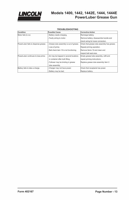
TROUBLESHOOTINGCondition Possible Cause Corrective ActionMotor fails to run. - Battery needs charging. Recharge battery.
- Faulty wiring to motor. Remove battery, disassemble handle and
check wiring for loose connection.PowerLuber fails to dispense grease. - Grease tube assembly is out of grease. Check that grease tube assembly has grease.
- Loss of prime. Repeat priming operation.
- Ball check item 19 is not functioning. Remove Items 19 and clean and
inspect ball seat area.PowerLuber continues to lose prime. - Air may be trapped in several locations Empty grease tube assembly, refill and
in container after bulk filling. repeat priming instructions.
- Follower may be binding in grease Replace grease tube assembly Item 2.
tube assembly.Battery fails to take a charge. - Charger may not have power. Check that receptacle has power.
- Battery may be bad. Replace battery.