Embed Size (px)
Citation preview
®
PN 1608592 March 2001 Rev.1, 9/03©2001-2003 Fluke Corporation. All rights reserved. Printed in U.S.A.
1
Models 110, 111 & 112Multimeters
Calibration Information
Introduction The Fluke Model 110, Model 111, and Model 112 True RMS Multimeters (hereafter "the Meter") are
battery-powered, with a 6000-count display and a bar graph.
This calibration information applies to all three models. All figures show the Model 112.
The Meter measures or tests the following:
• AC and DC voltage• Resistance• Continuity• Diodes• Frequency• Capacitance• AC and DC current (Model 111 and Model 112)
"Warning" and "Caution" Statements A "Warning" statement identifies hazardous conditions and actions that could cause bodily harm or
death.
A "Caution" statement identifies conditions and actions that could damage the Meter or the equipmentunder test.
Unsafe Voltage Symbol To alert you to the presence of a potentially hazardous voltage, the symbol is displayed when the Meter
detects a voltage ≥ 30 V or a voltage overload (OL) condition.
Test Lead Alert
WarningPersonal injury or damage to the Meter can occur if you attempt to make ameasurement with a lead in an incorrect terminal.
To remind you to check that the test leads are in the correct terminals, is displayed briefly when youmove the rotary switch to or from any A position.
These Meters meet CAT III IEC 61010-1-95 standards. The IEC 61010-1-95 safety standard defines fourovervoltage categories (CAT I to IV) based on the magnitude of danger from transient impulses. CAT IIImeters are designed to protect against transients in fixed-equipment installations at the distribution level.
Models 110, 111 & 112Calibration Information
2
WarningTo avoid electric shock or injury, do not perform the performance tests orcalibration procedures unless you are qualified to do so.
The information provided in this manual is for the use of qualified personnelonly.
This document provides the information necessary to calibrate and verify the performance of the FlukeModel 110, 111, and 112 Multimeters.
The following information is included:
• Safety Information and international symbols (Page 3)• Specifications (Pages 4 - 5)• Testing the fuse (Page 6)• Replacing the battery and fuse (Pages 7 - 8)• Replacing the LCD (Pages 9 - 10)• Performance tests (Pages 10 - 12)• Calibrating the Meter (Pages 13 - 14)• Display messages (Page 14)• Cleaning the Meter (Page 15)• User-replaceable parts (Page 16)
See the Models 110, 111 & 112 Users Manual for operating instructions.
Warranty and Service Information The Meter has a three year limited warranty, which is printed in the Users Manual.
To contact Fluke, call:
USA: 1-888-99-FLUKE (1-888-993-5853)Canada: 1-800-36-FLUKE (1-800-363-5853)Europe: +31 402-675-200Japan: +81-3-3434-0181Singapore: +65-738-5655Anywhere in the world: +1-425-446-5500
Or, visit Fluke’s Web site at www.fluke.com.
Safety Information
3
Safety Information
Warnings and PrecautionsTo avoid possible electric shock or personal injury, follow these guidelines:
• Use the Meter only as specified in this manual or the protection provided by the Meter mightbe impaired.
• Do not use the Meter or test leads if they appear damaged, or if the Meter is not operatingproperly.
• Always use proper terminals, switch position, and range for measurements.
• Verify the Meter’s operation by measuring a known voltage. If in doubt, have the Meterserviced.
• Do not apply more than the rated voltage, as marked on the Meter, between terminals orbetween any terminal and earth ground.
• Use caution with voltages above 30 V ac rms, 42 V ac peak, or 60 V dc. These voltages pose ashock hazard.
• To avoid false readings that can lead to electric shock and injury, replace the battery as soonas the low battery indicator () appears.
• Disconnect circuit power and discharge all high-voltage capacitors before testing resistance,continuity, diodes, or capacitance.
• Do not use the Meter around explosive gas or vapor.
• When using test leads or probes, keep your fingers behind the finger guards.
• Remove test leads from the Meter before opening the battery door or the Meter case.
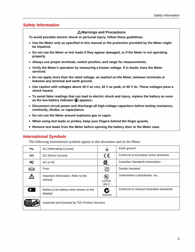
International Symbols The following international symbols appear in this document and on the Meter.
AC (Alternating Current) Earth ground
DC (Direct Current) Conforms to European Union directives
AC or DC Canadian Standards Association
Fuse Double insulated
Important Information. Refer to themanual. LISTED
950 Z
Underwriters Laboratories, Inc.
Battery (Low battery when shown on thedisplay) N10140
Conforms to relevant Australian standards
Inspected and licensed by TÜV Product Services
Models 110, 111 & 112Calibration Information
4
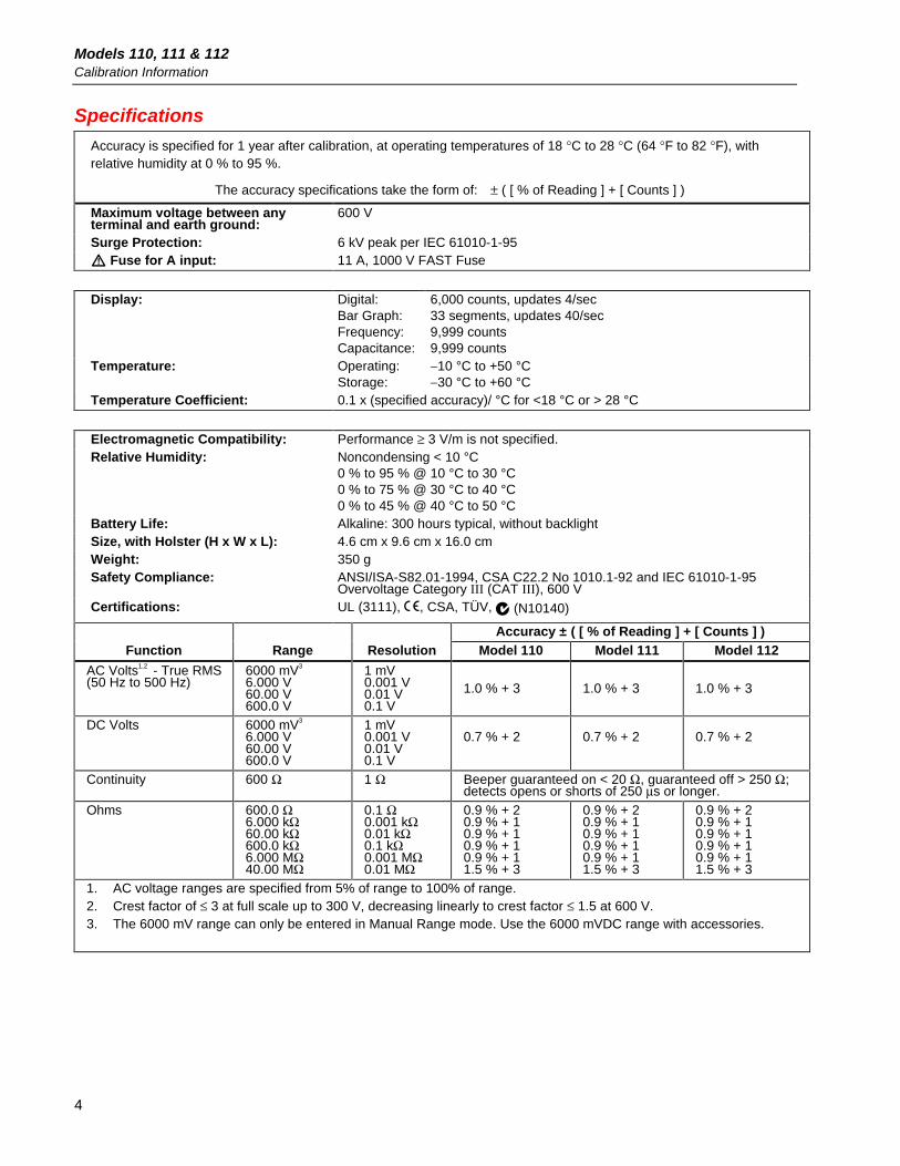
SpecificationsAccuracy is specified for 1 year after calibration, at operating temperatures of 18 °C to 28 °C (64 °F to 82 °F), withrelative humidity at 0 % to 95 %.
The accuracy specifications take the form of: ± ( [ % of Reading ] + [ Counts ] )
Maximum voltage between anyterminal and earth ground:
600 V
Surge Protection: 6 kV peak per IEC 61010-1-95 Fuse for A input: 11 A, 1000 V FAST Fuse
Display: Digital:Bar Graph:Frequency:Capacitance:
6,000 counts, updates 4/sec33 segments, updates 40/sec9,999 counts9,999 counts
Temperature: Operating:Storage:
−10 °C to +50 °C−30 °C to +60 °C
Temperature Coefficient: 0.1 x (specified accuracy)/ °C for <18 °C or > 28 °C
Electromagnetic Compatibility: Performance ≥ 3 V/m is not specified.Relative Humidity: Noncondensing < 10 °C
0 % to 95 % @ 10 °C to 30 °C0 % to 75 % @ 30 °C to 40 °C0 % to 45 % @ 40 °C to 50 °C
Battery Life: Alkaline: 300 hours typical, without backlightSize, with Holster (H x W x L): 4.6 cm x 9.6 cm x 16.0 cmWeight: 350 gSafety Compliance: ANSI/ISA-S82.01-1994, CSA C22.2 No 1010.1-92 and IEC 61010-1-95
Overvoltage Category III (CAT III), 600 VCertifications: UL (3111), , CSA, TÜV, (N10140)
Accuracy ± ( [ % of Reading ] + [ Counts ] )Function Range Resolution Model 110 Model 111 Model 112
AC Volts1,2 - True RMS(50 Hz to 500 Hz)
6000 mV3
6.000 V60.00 V600.0 V
1 mV0.001 V0.01 V0.1 V
1.0 % + 3 1.0 % + 3 1.0 % + 3
DC Volts 6000 mV3
6.000 V60.00 V600.0 V
1 mV0.001 V0.01 V0.1 V
0.7 % + 2 0.7 % + 2 0.7 % + 2
Continuity 600 Ω 1 Ω Beeper guaranteed on < 20 Ω, guaranteed off > 250 Ω;detects opens or shorts of 250 µs or longer.
Ohms 600.0 Ω6.000 kΩ60.00 kΩ600.0 kΩ6.000 MΩ40.00 MΩ
0.1 Ω0.001 kΩ0.01 kΩ0.1 kΩ0.001 MΩ0.01 MΩ
0.9 % + 20.9 % + 10.9 % + 10.9 % + 10.9 % + 11.5 % + 3
0.9 % + 20.9 % + 10.9 % + 10.9 % + 10.9 % + 11.5 % + 3
0.9 % + 20.9 % + 10.9 % + 10.9 % + 10.9 % + 11.5 % + 3
1. AC voltage ranges are specified from 5% of range to 100% of range.2. Crest factor of ≤ 3 at full scale up to 300 V, decreasing linearly to crest factor ≤ 1.5 at 600 V.3. The 6000 mV range can only be entered in Manual Range mode. Use the 6000 mVDC range with accessories.

Specifications
5
Specifications (continued)Accuracy ± ( [ % of Reading ] + [ Counts ] )
Function Range Resolution Model 110 Model 111 Model 112
Diode test 2.200 V 0.001 V 0.9 % + 21.9 % + 21.9 % + 21.9 % + 2
1.9 % + 21.9 % + 21.9 % + 2
1.9 % + 21.9 % + 21.9 % + 2
Capacitance4 1000 nF10.00 µF100.0 µF10000 µF
1 nF0.01 µF0.1 µF1 µF 100 µF - 1000 µF: 1.9% + 2
> 1000 µF: 10% + 90 typicalAC Amps5 - True RMS(50 Hz to 500 Hz)(Models 111 and 112)
10.00 Acontinuous or20 A overloadfor 30 secondsmaximum
0.01 A N/A 1.5 % + 3 1.5 % + 3
DC Amps(Models 111 and 112)
6.000 A10.00 Acontinuous or20 A overloadfor 30 secondsmaximum
0.001 A0.01 A
N/A 1.0 % + 3 1.0 % + 3
Hz6 (V or A input ) 99.99 Hz999.9 Hz9.999 kHz50.00 kHz
0.01 Hz0.1 Hz0.001 kHz0.01 kHz
0.1 % + 2 0.1 % + 2 0.1 % + 2
MIN MAX AVGAccuracy andResponse Time
Accuracy is the specified accuracy of the measurement function ± 12 digits for changes >200ms in duration (± 40 digits in AC). Typical response time: 100 ms to 80 % of signal, except VAC and A AC.
4. For film capacitors.5. Crest factor of ≤ 3. AC current is not specified below 3A.6. Hz is specified from 5 Hz to 50 kHz in volts, from 50 Hz to 5 kHz in amps.
FunctionInput Impedance
(Nominal) Common Mode Rejection RatioNormal Mode
RejectionVolts AC > 5 MΩ < 100 pF > 60 dB at DC, 50 Hz or 60 HzVolts DC > 10 MΩ < 100 pF > 100 dB at DC, 50 Hz or 60 Hz > 50 dB at 50 Hz or
60 HzFull Scale Voltage
Open Circuit TestVoltage
To 6 MΩ 40 MΩ Short Circuit Current
Ohms < 1.5 V DC < 600 mV DC < 1.5V DC < 500 µA
Diode test 2.4 to 3.0 V DC 2.400 V DC 1.2 mA typical
Models 110, 111 & 112Calibration Information
6
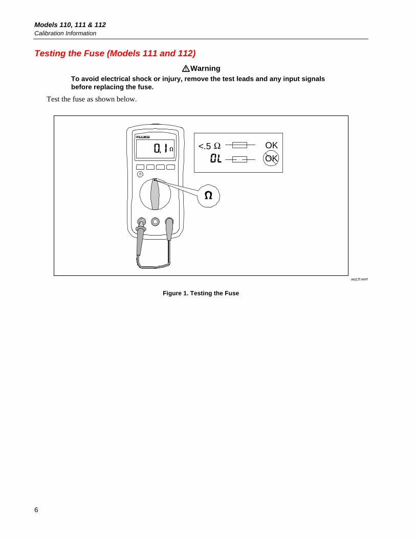
Testing the Fuse (Models 111 and 112)
WarningTo avoid electrical shock or injury, remove the test leads and any input signalsbefore replacing the fuse.
Test the fuse as shown below.
Ω <.5 OK
OK
aej12f.wmf
Figure 1. Testing the Fuse
Replacing the Battery and Fuse
7
Replacing the Battery and Fuse
WarningTo avoid electric shock, injury, or damage to the Meter:
• Remove test leads from the Meter before opening the case or battery door.
• Use ONLY a fuse with the amperage, interrupt, voltage, and speed ratingsspecified.
• Replace the battery as soon as the low battery indicator ( ) appears toavoid false readings.
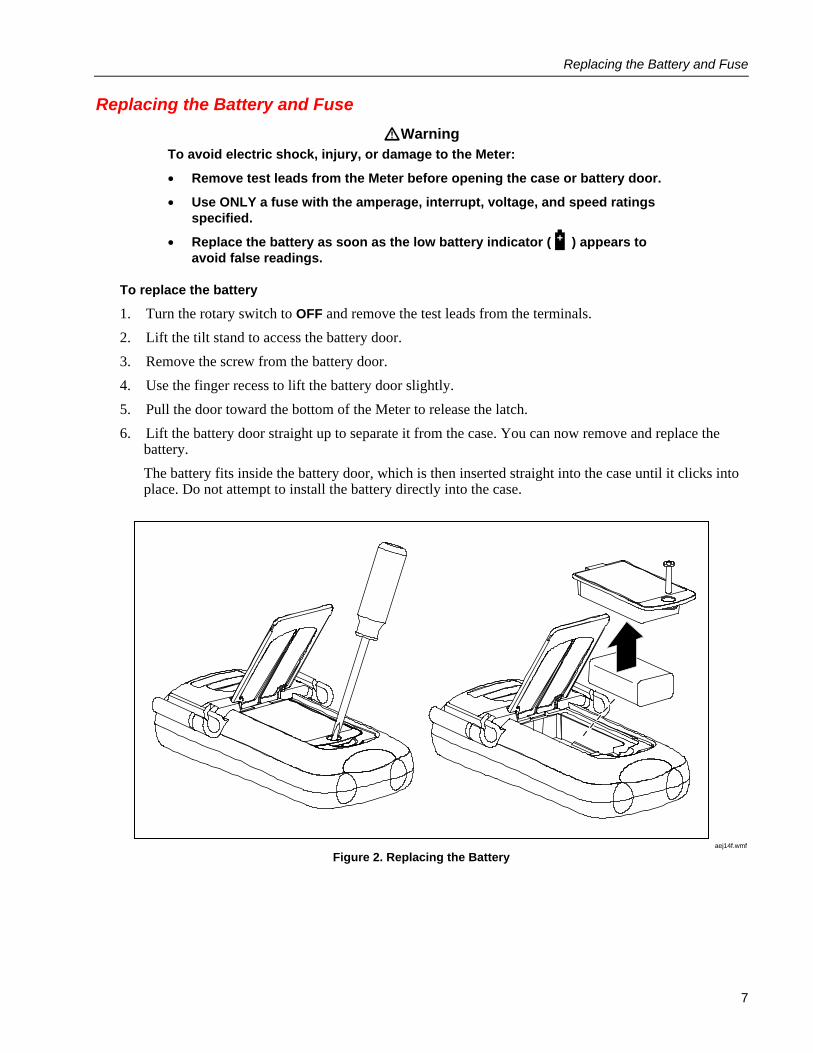
To replace the battery
1. Turn the rotary switch to OFF and remove the test leads from the terminals.
2. Lift the tilt stand to access the battery door.
3. Remove the screw from the battery door.
4. Use the finger recess to lift the battery door slightly.
5. Pull the door toward the bottom of the Meter to release the latch.
6. Lift the battery door straight up to separate it from the case. You can now remove and replace thebattery.
The battery fits inside the battery door, which is then inserted straight into the case until it clicks intoplace. Do not attempt to install the battery directly into the case.
aej14f.wmf
Figure 2. Replacing the Battery
Models 110, 111 & 112Calibration Information
8
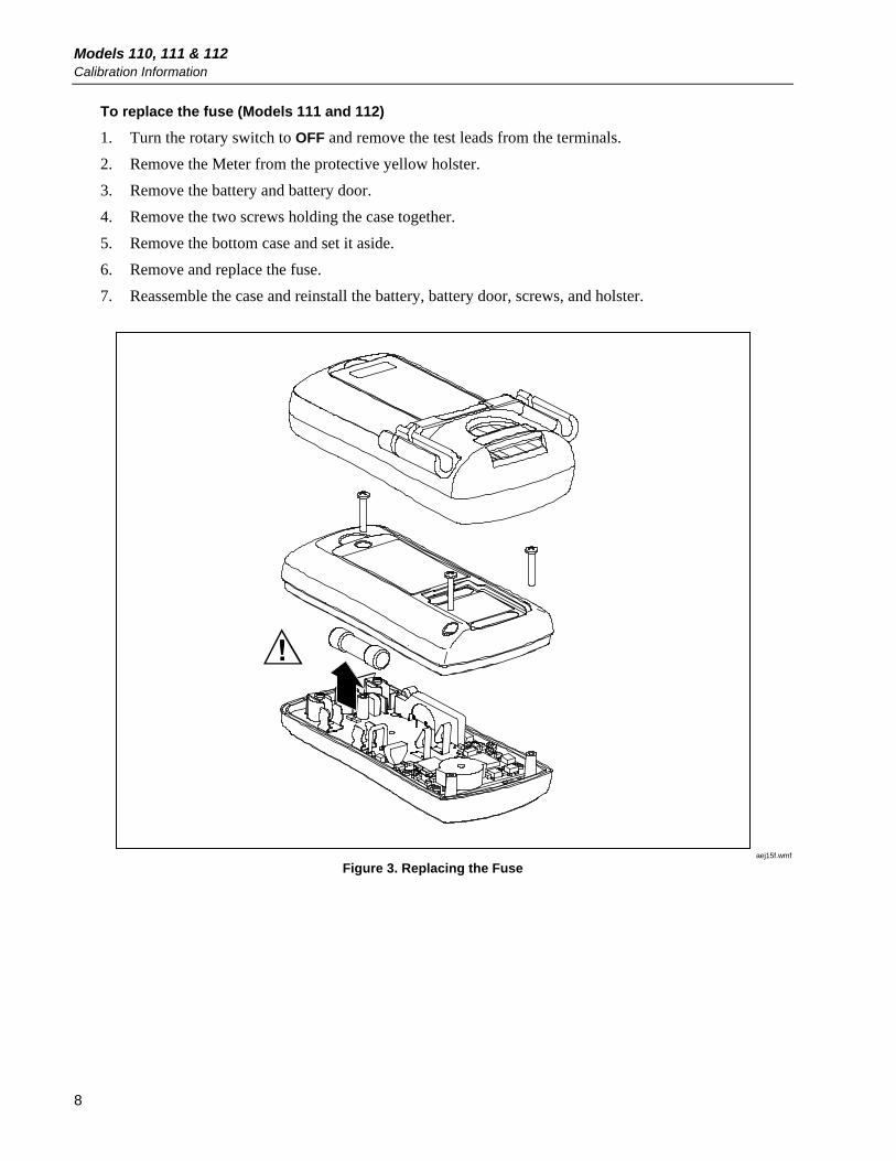
To replace the fuse (Models 111 and 112)
1. Turn the rotary switch to OFF and remove the test leads from the terminals.
2. Remove the Meter from the protective yellow holster.
3. Remove the battery and battery door.
4. Remove the two screws holding the case together.
5. Remove the bottom case and set it aside.
6. Remove and replace the fuse.
7. Reassemble the case and reinstall the battery, battery door, screws, and holster.
aej15f.wmf
Figure 3. Replacing the Fuse
Replacing the LCD
9
Replacing the LCD You must remove the circuit board assembly to access and replace the LCD.
CautionThe circuit board is extremely susceptible to contamination. To avoidcontamination, handle it by the input receptacle, fuse clips, or edges of theboard only. You can also use clean surgical gloves to help avoid contamination.
To replace the LCD
1. Turn the rotary switch to OFF and remove the test leads from the terminals.
2. Open the case as described earlier.
3. Remove the 3 Phillips screws securing the input terminals to the case top.
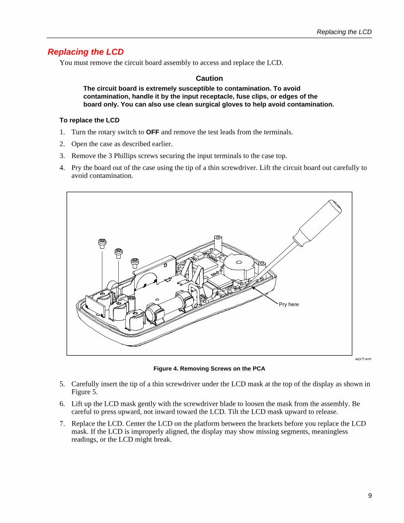
4. Pry the board out of the case using the tip of a thin screwdriver. Lift the circuit board out carefully toavoid contamination.
Pry here
aej17f.wmf
Figure 4. Removing Screws on the PCA
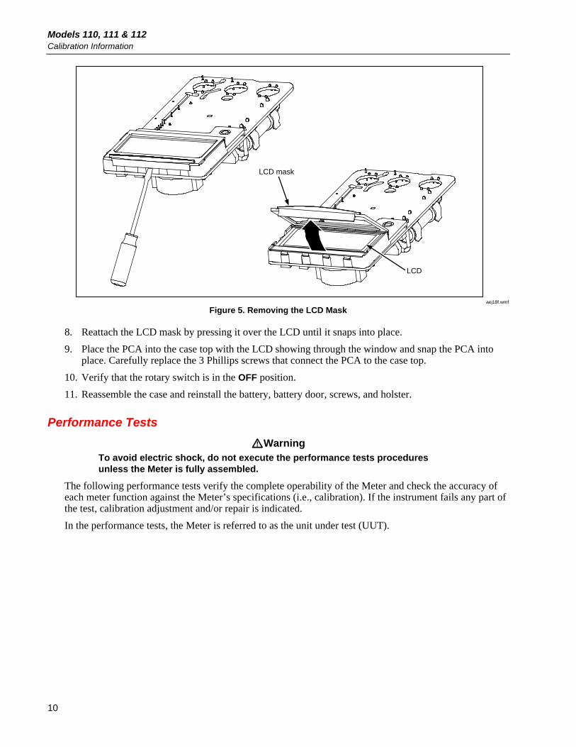
5. Carefully insert the tip of a thin screwdriver under the LCD mask at the top of the display as shown inFigure 5.
6. Lift up the LCD mask gently with the screwdriver blade to loosen the mask from the assembly. Becareful to press upward, not inward toward the LCD. Tilt the LCD mask upward to release.
7. Replace the LCD. Center the LCD on the platform between the brackets before you replace the LCDmask. If the LCD is improperly aligned, the display may show missing segments, meaninglessreadings, or the LCD might break.
Models 110, 111 & 112Calibration Information
10
LCD mask
LCD
aej18f.wmf
Figure 5. Removing the LCD Mask
8. Reattach the LCD mask by pressing it over the LCD until it snaps into place.
9. Place the PCA into the case top with the LCD showing through the window and snap the PCA intoplace. Carefully replace the 3 Phillips screws that connect the PCA to the case top.
10. Verify that the rotary switch is in the OFF position.
11. Reassemble the case and reinstall the battery, battery door, screws, and holster.
Performance Tests
WarningTo avoid electric shock, do not execute the performance tests proceduresunless the Meter is fully assembled.
The following performance tests verify the complete operability of the Meter and check the accuracy ofeach meter function against the Meter’s specifications (i.e., calibration). If the instrument fails any part ofthe test, calibration adjustment and/or repair is indicated.
In the performance tests, the Meter is referred to as the unit under test (UUT).
Performance Tests
11
Required Equipment A Fluke 5500A Multi-Product Calibrator (or equivalent) is required for the performance test procedures
in this document.
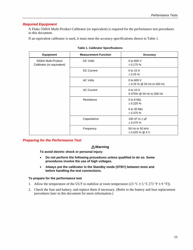
If an equivalent calibrator is used, it must meet the accuracy specifications shown in Table 1.
Table 1. Calibrator Specifications
Equipment Measurement Function Accuracy
5500A Multi-ProductCalibrator (or equivalent)
DC Volts 0 to 600 V± 0.175 %
DC Current 0 to 10 A± 0.25 %
AC Volts 0 to 600 V± 0.25 % @ 50 Hz to 500 Hz
AC Current 0 to 10 A0.375% @ 50 Hz to 500 Hz
Resistance 0 to 6 MΩ± 0.225 %
6 to 30 MΩ± 0.375 %
Capacitance 100 nF to 1 µF± 0.475 %
Frequency 50 Hz to 50 kHz± 0.025 % @ 5 V
Preparing for the Performance Test
WarningTo avoid electric shock or personal injury:
• Do not perform the following procedures unless qualified to do so. Someprocedures involve the use of high voltages.
• Always put the calibrator in the Standby mode (STBY) between tests andbefore handling the test connections.
To prepare for the performance test
1. Allow the temperature of the UUT to stabilize at room temperature (23 °C ± 5 °C [73 °F ± 9 °F]).
2. Check the fuse and battery, and replace them if necessary. (Refer to the battery and fuse replacementprocedures later in this document for more information.)
Models 110, 111 & 112Calibration Information
12
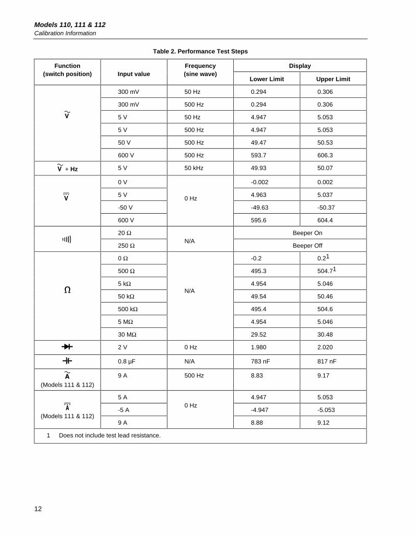
Table 2. Performance Test Steps
DisplayFunction(switch position) Input value
Frequency(sine wave)
Lower Limit Upper Limit
300 mV 50 Hz 0.294 0.306
300 mV 500 Hz 0.294 0.306
5 V 50 Hz 4.947 5.053
5 V 500 Hz 4.947 5.053
50 V 500 Hz 49.47 50.53
600 V 500 Hz 593.7 606.3
+ Hz 5 V 50 kHz 49.93 50.07
0 V -0.002 0.002
5 V 4.963 5.037
-50 V -49.63 -50.37
600 V
0 Hz
595.6 604.4
20 Ω Beeper On
250 ΩN/A
Beeper Off
0 Ω -0.2 0.21
500 Ω 495.3 504.71
5 kΩ 4.954 5.046
50 kΩ 49.54 50.46
500 kΩ 495.4 504.6
5 MΩ 4.954 5.046
30 MΩ
N/A
29.52 30.48
2 V 0 Hz 1.980 2.020
0.8 µF N/A 783 nF 817 nF
(Models 111 & 112)
9 A 500 Hz 8.83 9.17
5 A 4.947 5.053
-5 A -4.947 -5.053(Models 111 & 112)
9 A
0 Hz
8.88 9.12
1 Does not include test lead resistance.
Calibrating the Meter
13
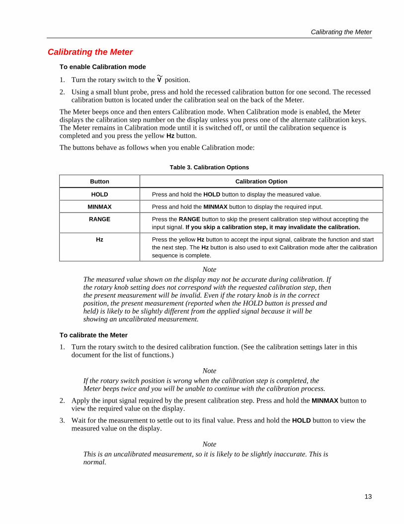
Calibrating the Meter
To enable Calibration mode
1. Turn the rotary switch to the position.
2. Using a small blunt probe, press and hold the recessed calibration button for one second. The recessedcalibration button is located under the calibration seal on the back of the Meter.
The Meter beeps once and then enters Calibration mode. When Calibration mode is enabled, the Meterdisplays the calibration step number on the display unless you press one of the alternate calibration keys.The Meter remains in Calibration mode until it is switched off, or until the calibration sequence iscompleted and you press the yellow Hz button.
The buttons behave as follows when you enable Calibration mode:
Table 3. Calibration Options
Button Calibration Option
HOLD Press and hold the HOLD button to display the measured value.
MINMAX Press and hold the MINMAX button to display the required input.
RANGE Press the RANGE button to skip the present calibration step without accepting theinput signal. If you skip a calibration step, it may invalidate the calibration.
Hz Press the yellow Hz button to accept the input signal, calibrate the function and startthe next step. The Hz button is also used to exit Calibration mode after the calibrationsequence is complete.
NoteThe measured value shown on the display may not be accurate during calibration. Ifthe rotary knob setting does not correspond with the requested calibration step, thenthe present measurement will be invalid. Even if the rotary knob is in the correctposition, the present measurement (reported when the HOLD button is pressed andheld) is likely to be slightly different from the applied signal because it will beshowing an uncalibrated measurement.
To calibrate the Meter
1. Turn the rotary switch to the desired calibration function. (See the calibration settings later in thisdocument for the list of functions.)
NoteIf the rotary switch position is wrong when the calibration step is completed, theMeter beeps twice and you will be unable to continue with the calibration process.
2. Apply the input signal required by the present calibration step. Press and hold the MINMAX button toview the required value on the display.
3. Wait for the measurement to settle out to its final value. Press and hold the HOLD button to view themeasured value on the display.
NoteThis is an uncalibrated measurement, so it is likely to be slightly inaccurate. This isnormal.

Models 110, 111 & 112Calibration Information
14
4. Press the yellow Hz button to proceed to the next step. The Meter records a new constant.
5. Repeat steps 1 through 4 until the display shows “End”. This indicates that the calibration procedureis complete. Press the yellow Hz button to resume normal operation, or switch the Meter off.
Calibration Settings
NoteThe “Seconds to settle” column does not include calibrator settling time.
Table 4. Calibration Settings for the Fluke 110
StepNumber
Function(switch position) Input value
Frequency(sine wave)
Secondsto Settle
C-01 - Hz 6.000 V 900.0 Hz 4
C-02 6.000 V 60 Hz 2
C-03 6.000 V DC 1
C-04 600 N/A 1
C-05 6.000 k N/A 1
Table 5. Calibration Settings for the Fluke 111 and 112
StepNumber
Function(switch position Input value
Frequency(sine wave)
Secondsto Settle
C-01 - Hz 6.000 V 900.0 Hz 4
C-02 6.000 V 60 Hz 2
C-03 6.000 V DC 1
C-04 600 N/A 1
C-05 6.000 k N/A 1
C-06 (use Amps jack)
6.000 A DC 1
*C-07 6.000A DC 1
* For meters above S/N 83630079
Display Messages If the calibration procedure is not completed correctly, the Meter will not operate correctly. If calibration
is not completed correctly, the Meter alternates the messages “CaL” and “Err” on the display and you willneed to recalibrate the Meter. The meter is damaged and requires service if:
• “CaL” and “Err” messages continue to appear after a proper recalibration.
• “EEPr” and “Err” messages are alternating on the display.
• “EEPr” message appears on the display.

Cleaning the Meter
15
Cleaning the Meter
WarningTo avoid electrical shock or damage to the Meter, never allow water inside thecase. To avoid damaging the housing, never apply solvents to the Meter.
• Periodically wipe the case with a damp cloth and mild detergent. Do not use abrasives or solvents.
• Dirt or moisture in the input terminals can distort meter readings. Clean the terminals as follows:
1. Turn the rotary switch to OFF and remove the test leads from the terminals.
2. Shake out any dirt that may be in the terminals.
3. Soak a new swab with alcohol. Clean each terminal with the swab.
Models 110, 111 & 112Calibration Information
16
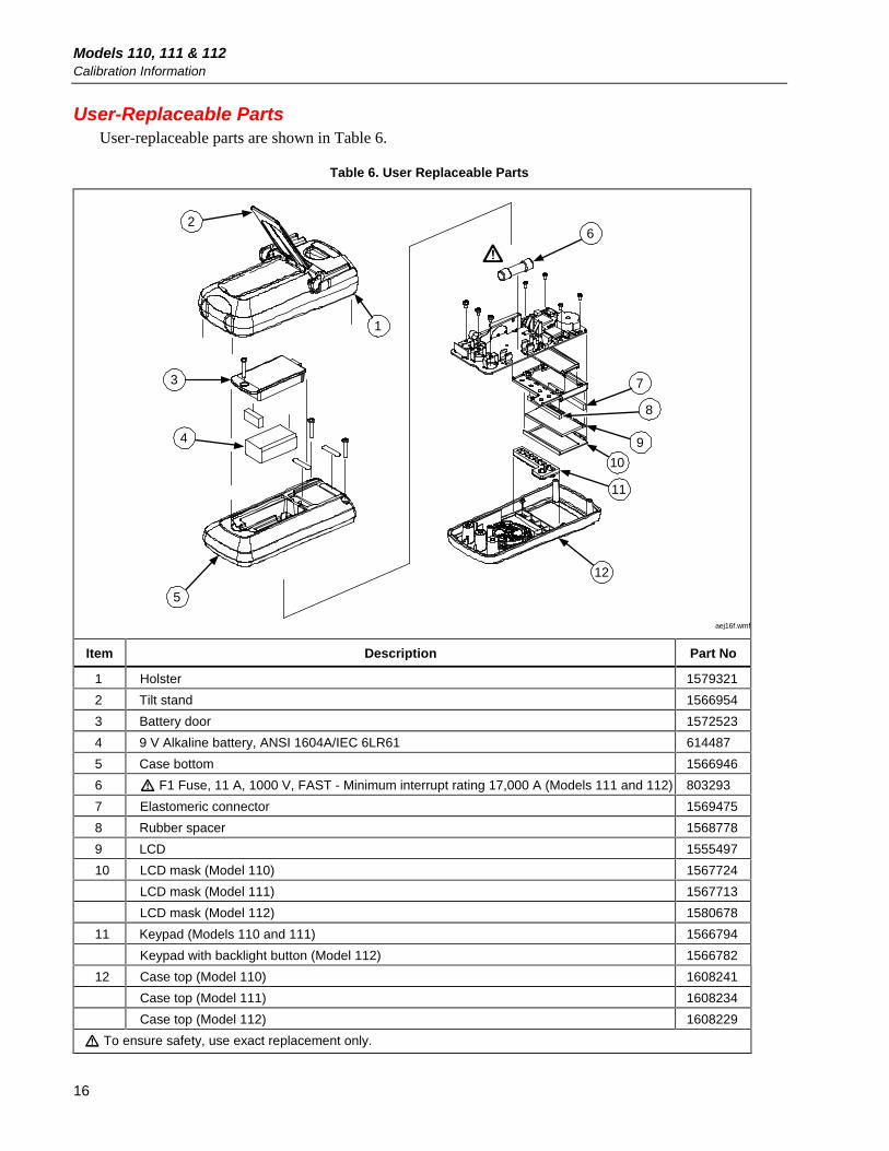
User-Replaceable Parts User-replaceable parts are shown in Table 6.
Table 6. User Replaceable Parts
2
3
4
5
1
6
8
7
9
10
11
12
aej16f.wmf
Item Description Part No
1 Holster 1579321
2 Tilt stand 1566954
3 Battery door 1572523
4 9 V Alkaline battery, ANSI 1604A/IEC 6LR61 614487
5 Case bottom 1566946
6 F1 Fuse, 11 A, 1000 V, FAST - Minimum interrupt rating 17,000 A (Models 111 and 112) 803293
7 Elastomeric connector 1569475
8 Rubber spacer 1568778
9 LCD 1555497
10 LCD mask (Model 110) 1567724
LCD mask (Model 111) 1567713
LCD mask (Model 112) 1580678
11 Keypad (Models 110 and 111) 1566794
Keypad with backlight button (Model 112) 1566782
12 Case top (Model 110) 1608241
Case top (Model 111) 1608234
Case top (Model 112) 1608229
To ensure safety, use exact replacement only.