Embed Size (px)
Citation preview
Modelling vesicle dynamics
Badr KAOUICASA‐W&I‐TU/e (Eindhoven, The Netherlands)
Eindhoven, October 28, 2009
2
Contents
• What is a vesicle?
• Vesicle dynamics under Poiseuille flowusing the boundary integral method (BIM)
• Vesicle dynamics in confined geometries and in micro‐fluidic devicesusing the lattice‐Boltzmann method (LBM)
• Conclusions
3
What is a vesicle?
4
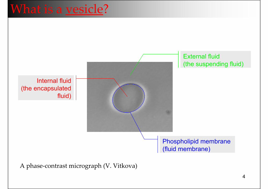
What is a vesicle?
Phospholipid membrane(fluid membrane)
Internal fluid(the encapsulated
fluid)
External fluid(the suspending fluid)
A phase‐contrast micrograph (V. Vitkova)
5
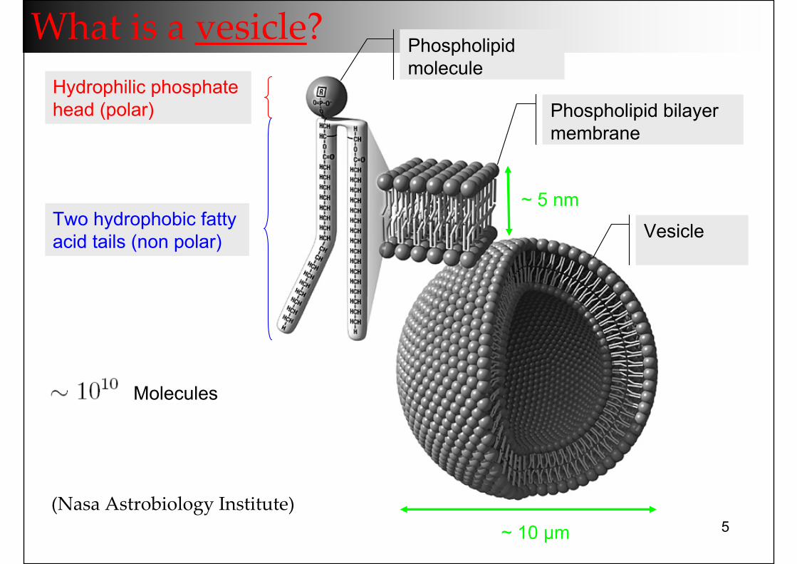
What is a vesicle?
(Nasa Astrobiology Institute)
Hydrophilic phosphate head (polar)
Two hydrophobic fatty acid tails (non polar)
Phospholipidmolecule
Phospholipid bilayermembrane
Vesicle
~ 10 µm
~ 5 nm
Molecules
6
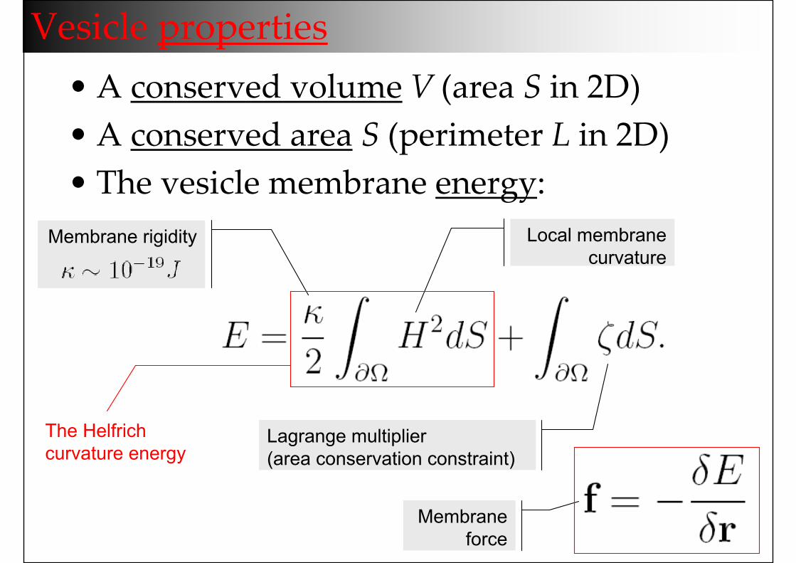
Vesicle properties• A conserved volume V (area S in 2D)• A conserved area S (perimeter L in 2D)• The vesicle membrane energy:
Membrane rigidity Local membrane curvature
Lagrange multiplier (area conservation constraint)
The Helfrichcurvature energy
Membrane force
7
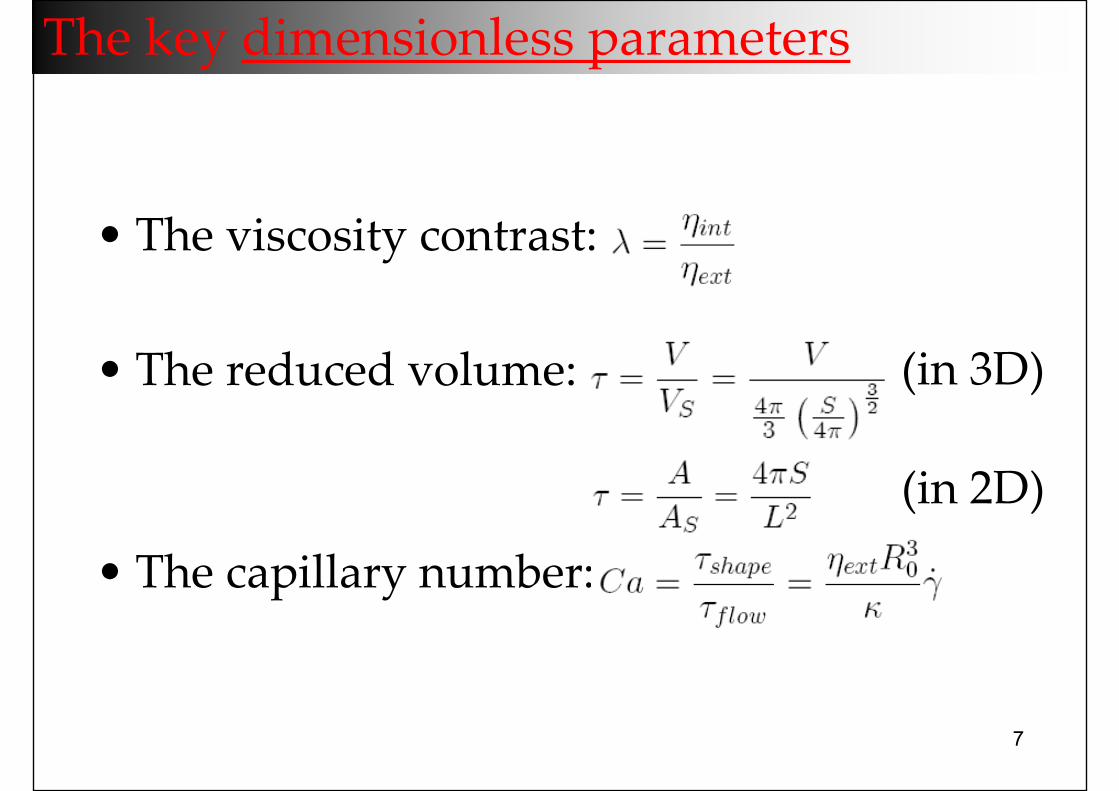
• The viscosity contrast:
• The reduced volume:
• The capillary number:
(in 3D)
(in 2D)
The key dimensionless parameters
8
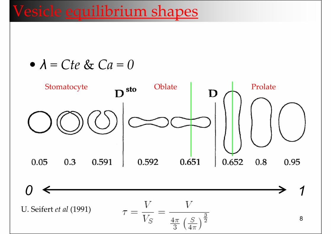
Vesicle equilibrium shapes
ProlateOblateStomatocyte
U. Seifert et al (1991)
0 1
• λ = Cte & Ca = 0
9
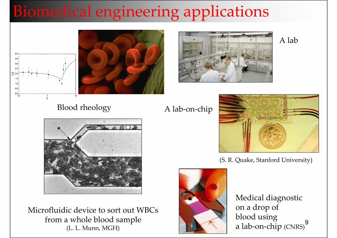
Biomedical engineering applications
Blood rheology
Microfluidic device to sort out WBCsfrom a whole blood sample
(L. L. Munn, MGH)
Medical diagnostic on a drop of blood usinga lab‐on‐chip (CNRS)
A lab‐on‐chip
(S. R. Quake, Stanford University)
A lab
10
Vesicle dynamics under unbounded Poiseuille flow
11
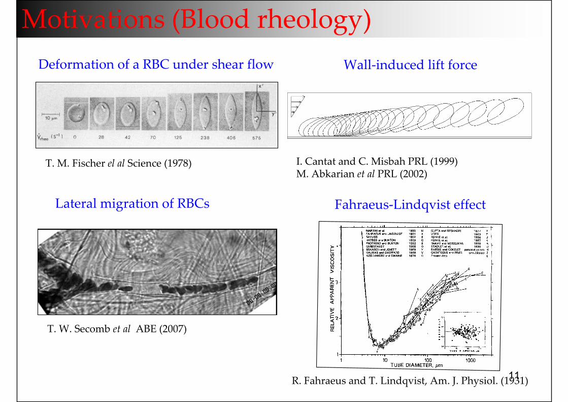
Motivations (Blood rheology)
I. Cantat and C. Misbah PRL (1999)M. Abkarian et al PRL (2002)
Wall‐induced lift force
Fahraeus‐Lindqvist effectLateral migration of RBCs
T. W. Secomb et al ABE (2007)
Deformation of a RBC under shear flow
R. Fahraeus and T. Lindqvist, Am. J. Physiol. (1931)
T. M. Fischer el al Science (1978)
12
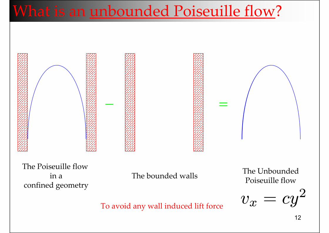
What is an unbounded Poiseuille flow?
− =
The Poiseuille flow in a
confined geometryThe bounded walls The Unbounded
Poiseuille flow
To avoid any wall induced lift force vx = cy2
13
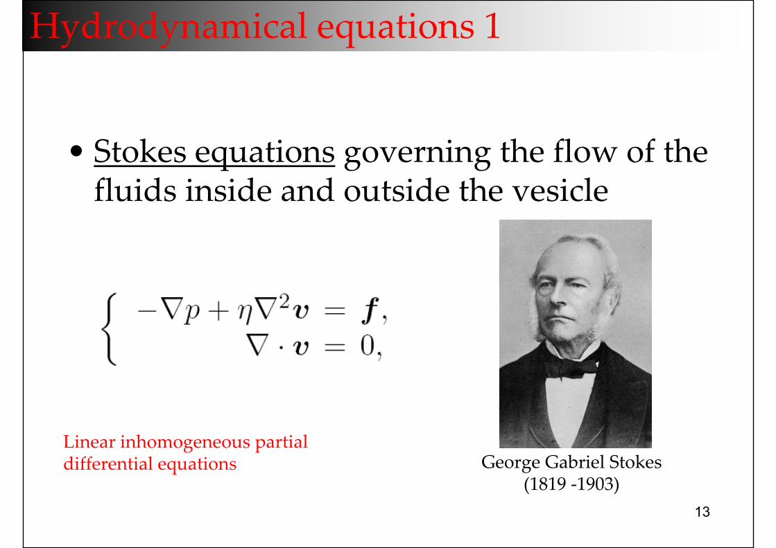
Hydrodynamical equations 1
• Stokes equations governing the flow of the fluids inside and outside the vesicle
Linear inhomogeneous partial differential equations George Gabriel Stokes
(1819 ‐1903)
14
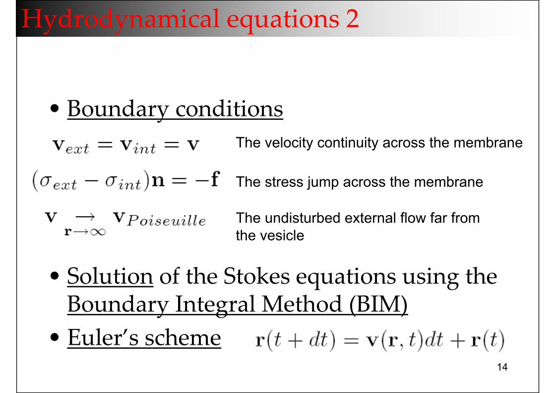
Hydrodynamical equations 2
The velocity continuity across the membrane
The stress jump across the membrane
The undisturbed external flow far from the vesicle
• Boundary conditions
• Solution of the Stokes equations using the Boundary Integral Method (BIM)
• Euler’s scheme
15
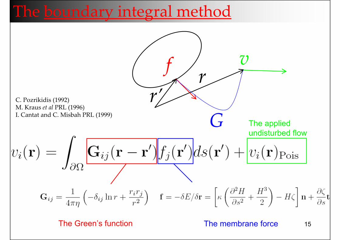
The boundary integral method
The Green’s function The membrane force
The applied undisturbed flow
f v
Gr’
rC. Pozrikidis (1992)M. Kraus et al PRL (1996)I. Cantat and C. Misbah PRL (1999)
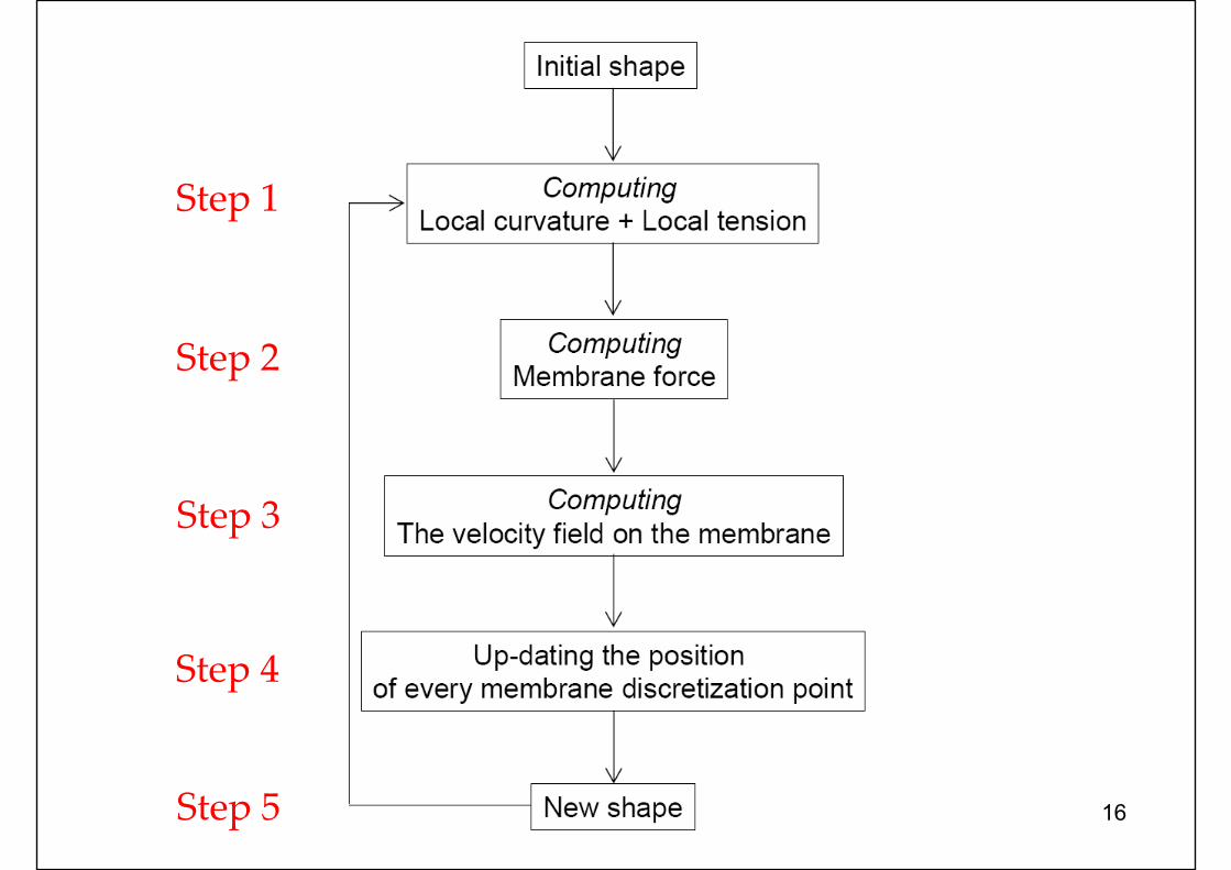
16
Step 1
Step 2
Step 3
Step 4
Step 5
17
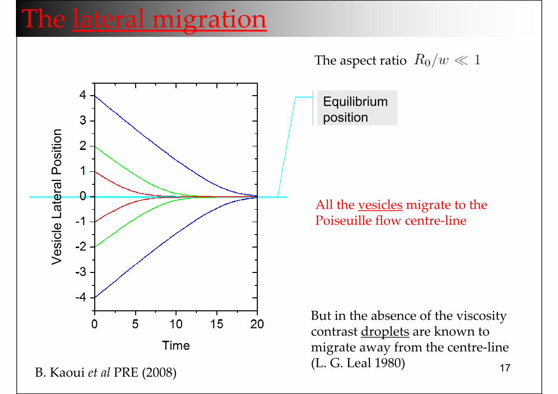
The lateral migration
All the vesicles migrate to the Poiseuille flow centre‐line
Equilibrium position
But in the absence of the viscosity contrast droplets are known to migrate away from the centre‐line(L. G. Leal 1980)
Ves
icle
Lat
eral
Pos
ition
The aspect ratio
B. Kaoui et al PRE (2008)
18
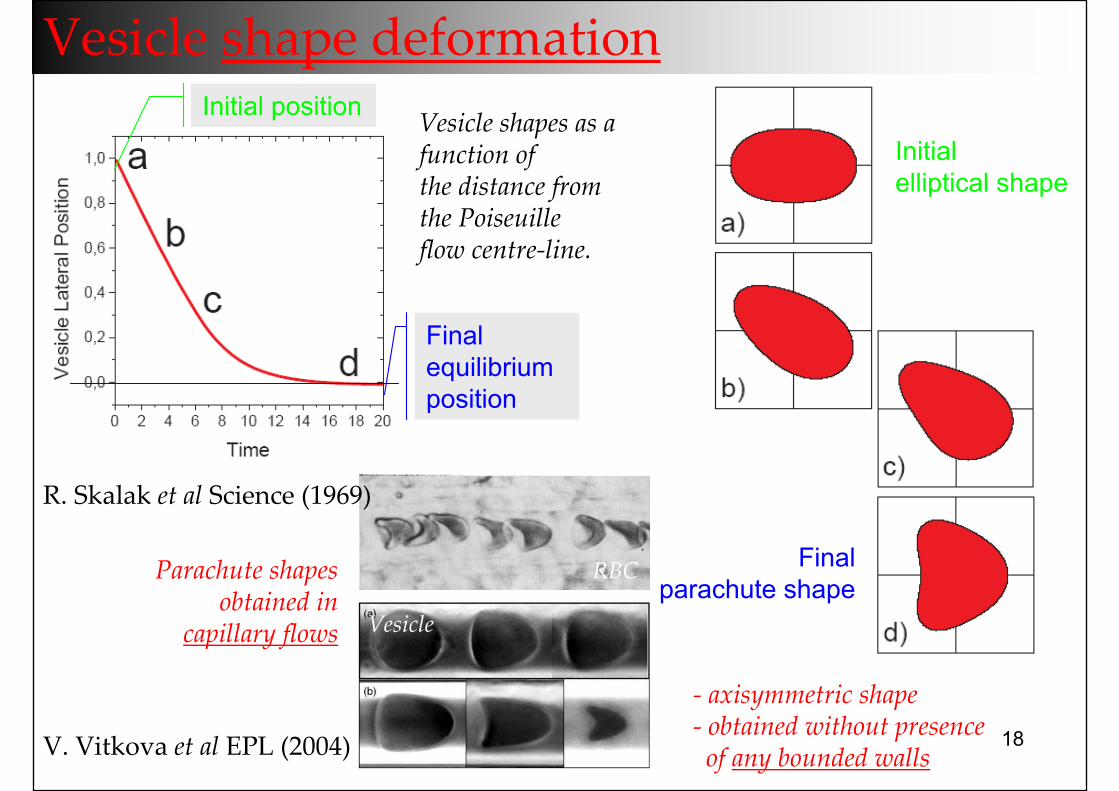
Vesicle shape deformation
Initial elliptical shape
Finalparachute shape
Vesicle shapes as a function of the distance from the Poiseuilleflow centre‐line.
Initial position
Final equilibrium position
V. Vitkova et al EPL (2004)
Parachute shapes obtained in
capillary flows
‐ axisymmetric shape‐ obtained without presence of any bounded walls
R. Skalak et al Science (1969)
RBC
Vesicle
19
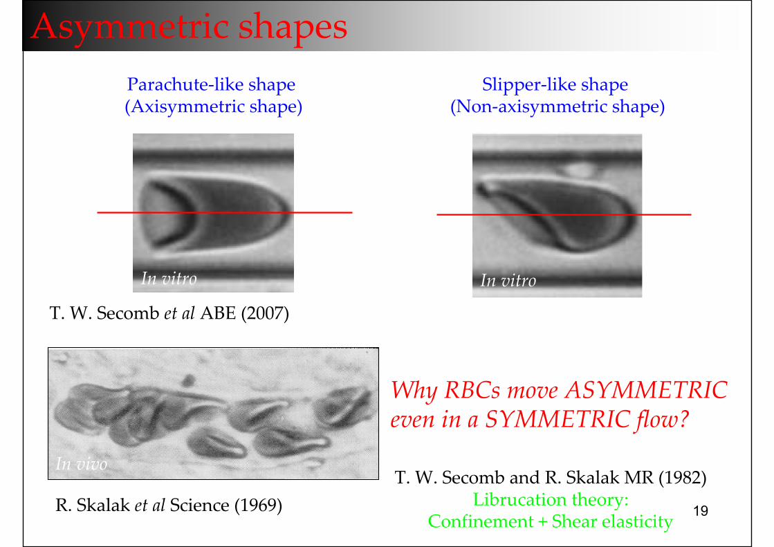
T. W. Secomb et al ABE (2007)
In vitroIn vitro
Parachute‐like shape(Axisymmetric shape)
Slipper‐like shape(Non‐axisymmetric shape)
Asymmetric shapes
R. Skalak et al Science (1969)
In vivo
Why RBCs move ASYMMETRICeven in a SYMMETRIC flow?
T. W. Secomb and R. Skalak MR (1982)Librucation theory:
Confinement + Shear elasticity
20
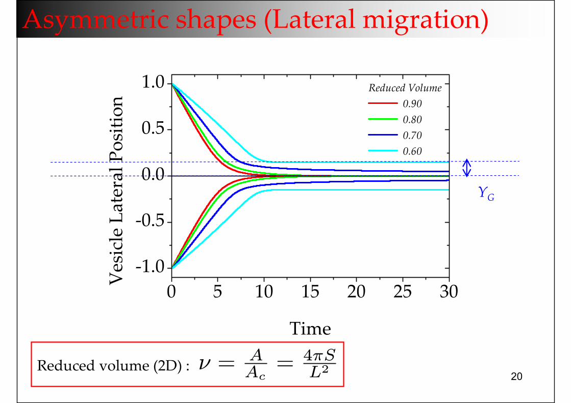
0 5 10 15 20 25 30‐1.0
‐0.5
0.0
0.5
1.0
Reduced Volume 0.90 0.80 0.70 0.60
Vesicle Lateral Position
Time
Asymmetric shapes (Lateral migration)
YG
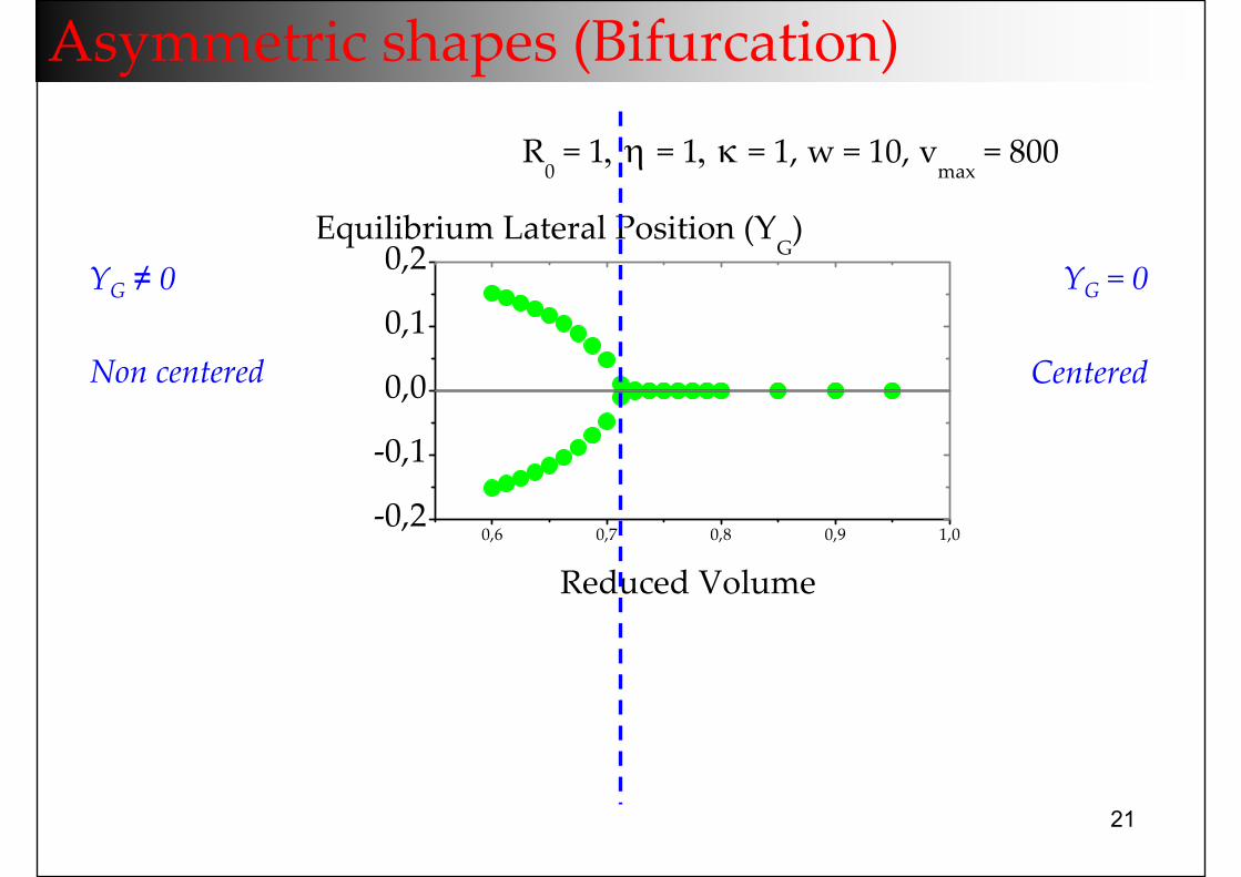
Reduced volume (2D) : ν = AAc= 4πS
L2
21
0,6 0,7 0,8 0,9 1,0‐0,2
‐0,1
0,0
0,1
0,2
Reduced Volume
R0 = 1, η = 1, κ = 1, w = 10, v
max = 800
Equilibrium Lateral Position (Y
G)
Asymmetric shapes (Bifurcation)
CenteredNon centered
YG = 0YG ≠ 0
22
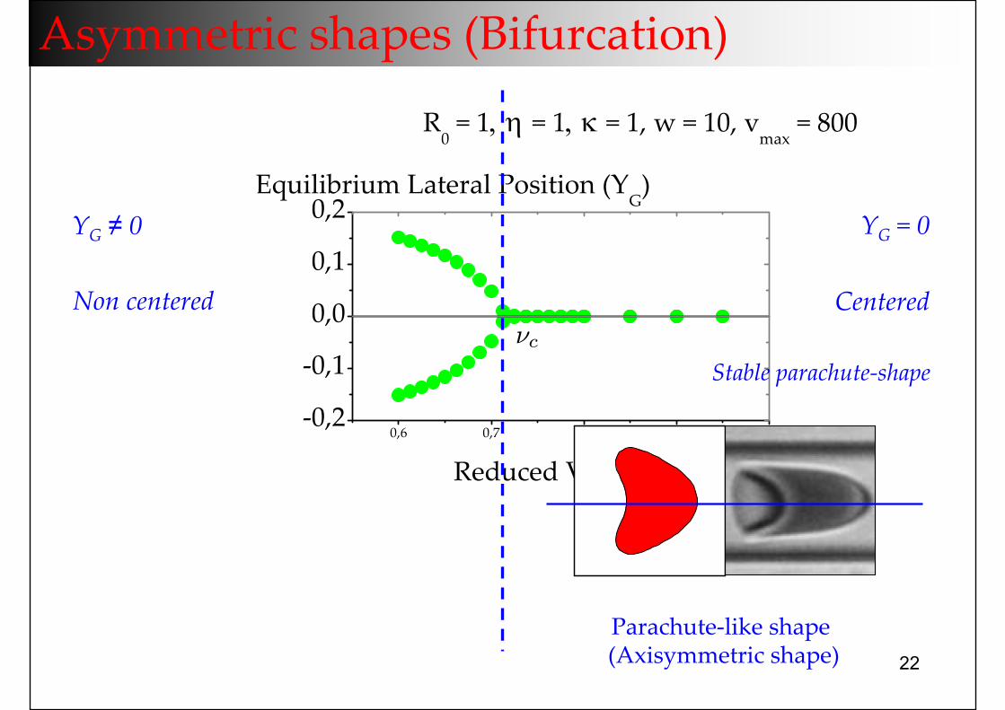
0,6 0,7 0,8 0,9 1,0‐0,2
‐0,1
0,0
0,1
0,2
Reduced Volume
R0 = 1, η = 1, κ = 1, w = 10, v
max = 800
Equilibrium Lateral Position (Y
G)
Asymmetric shapes (Bifurcation)
CenteredNon centered
YG = 0YG ≠ 0
Parachute‐like shape(Axisymmetric shape)
Stable parachute‐shapeνc
23
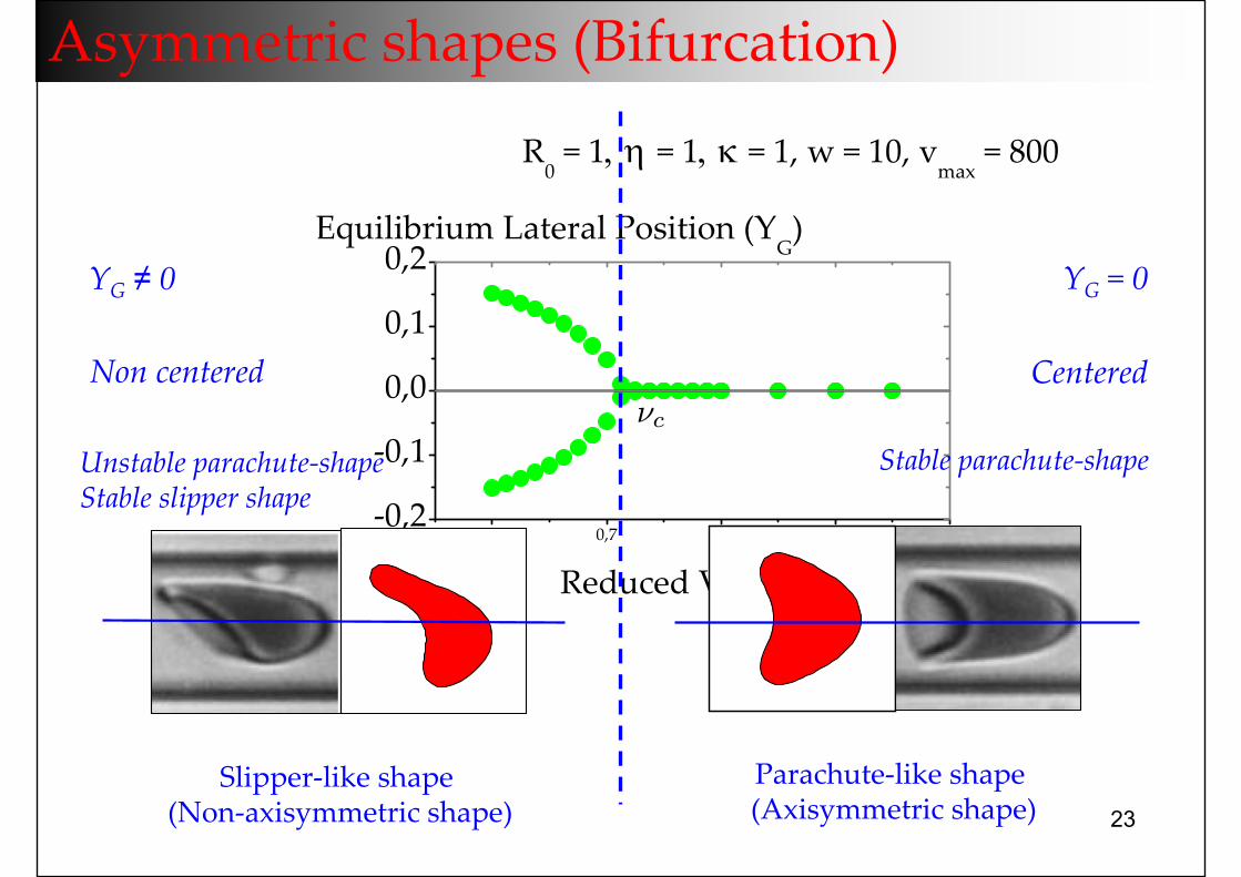
0,6 0,7 0,8 0,9 1,0‐0,2
‐0,1
0,0
0,1
0,2
Reduced Volume
R0 = 1, η = 1, κ = 1, w = 10, v
max = 800
Equilibrium Lateral Position (Y
G)
Asymmetric shapes (Bifurcation)
CenteredNon centered
YG = 0YG ≠ 0
Parachute‐like shape(Axisymmetric shape)
Slipper‐like shape(Non‐axisymmetric shape)
Stable parachute‐shapeUnstable parachute‐shapeStable slipper shape
νc
24
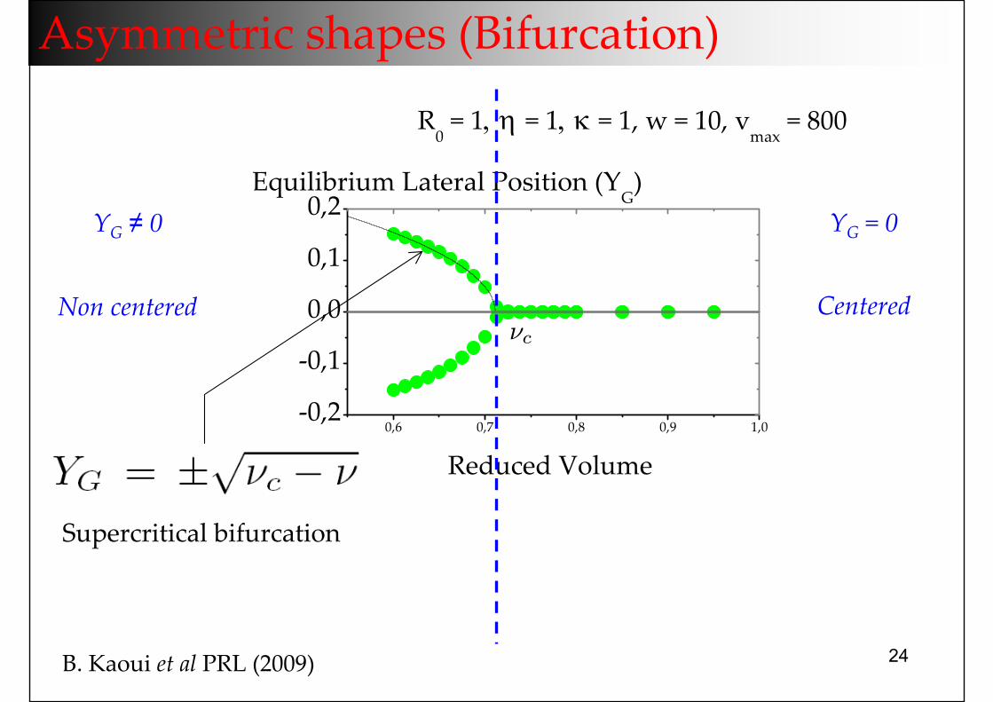
0,6 0,7 0,8 0,9 1,0‐0,2
‐0,1
0,0
0,1
0,2
Reduced Volume
R0 = 1, η = 1, κ = 1, w = 10, v
max = 800
Equilibrium Lateral Position (Y
G)
Asymmetric shapes (Bifurcation)
CenteredNon centered
YG = 0YG ≠ 0
Supercritical bifurcation
νc
B. Kaoui et al PRL (2009)
25
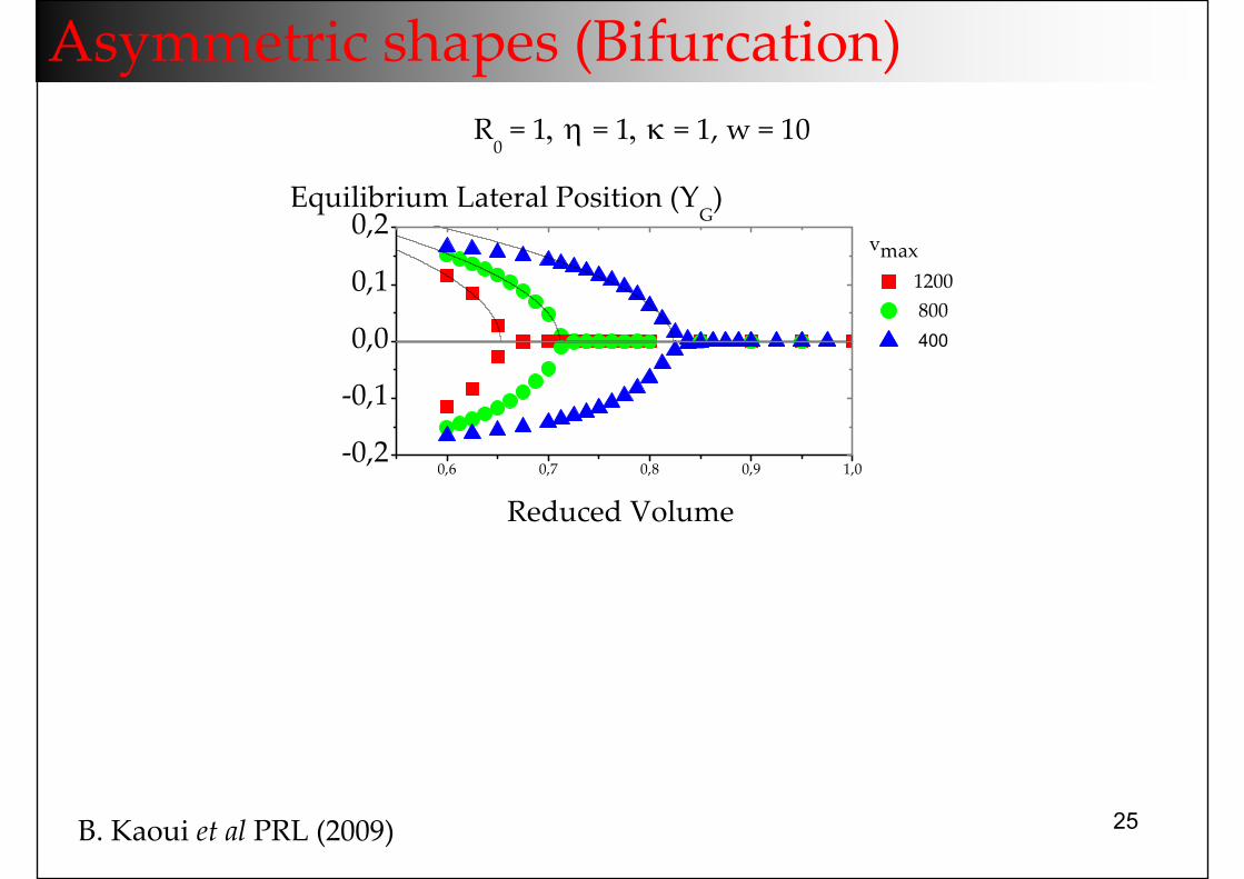
0,6 0,7 0,8 0,9 1,0‐0,2
‐0,1
0,0
0,1
0,2
Reduced Volume
vmax 1200 800 400
R0 = 1, η = 1, κ = 1, w = 10
Equilibrium Lateral Position (Y
G)
Asymmetric shapes (Bifurcation)
B. Kaoui et al PRL (2009)
26
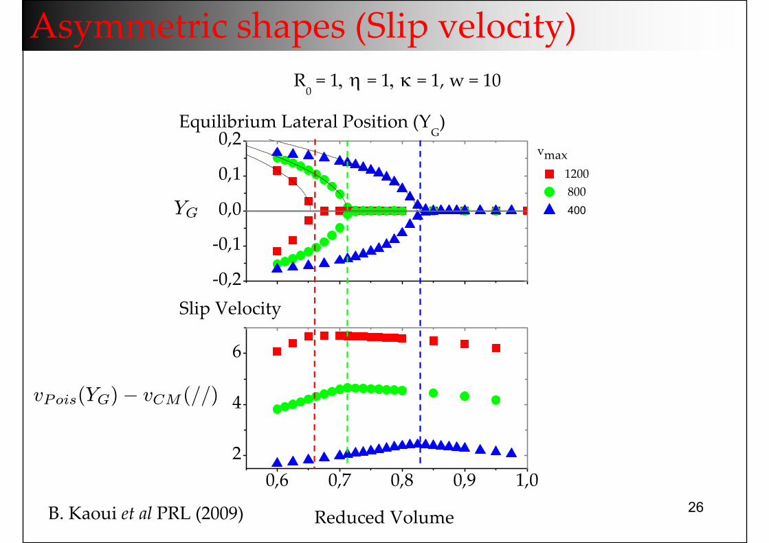
0,6 0,7 0,8 0,9 1,02
4
6
‐0,2
‐0,1
0,0
0,1
0,2
vmax 1200 800 400
R0 = 1, η = 1, κ = 1, w = 10
Equilibrium Lateral Position (Y
G)
Reduced Volume
Slip Velocity
Asymmetric shapes (Slip velocity)
YG
vPois(YG)− vCM (//)
B. Kaoui et al PRL (2009)
27
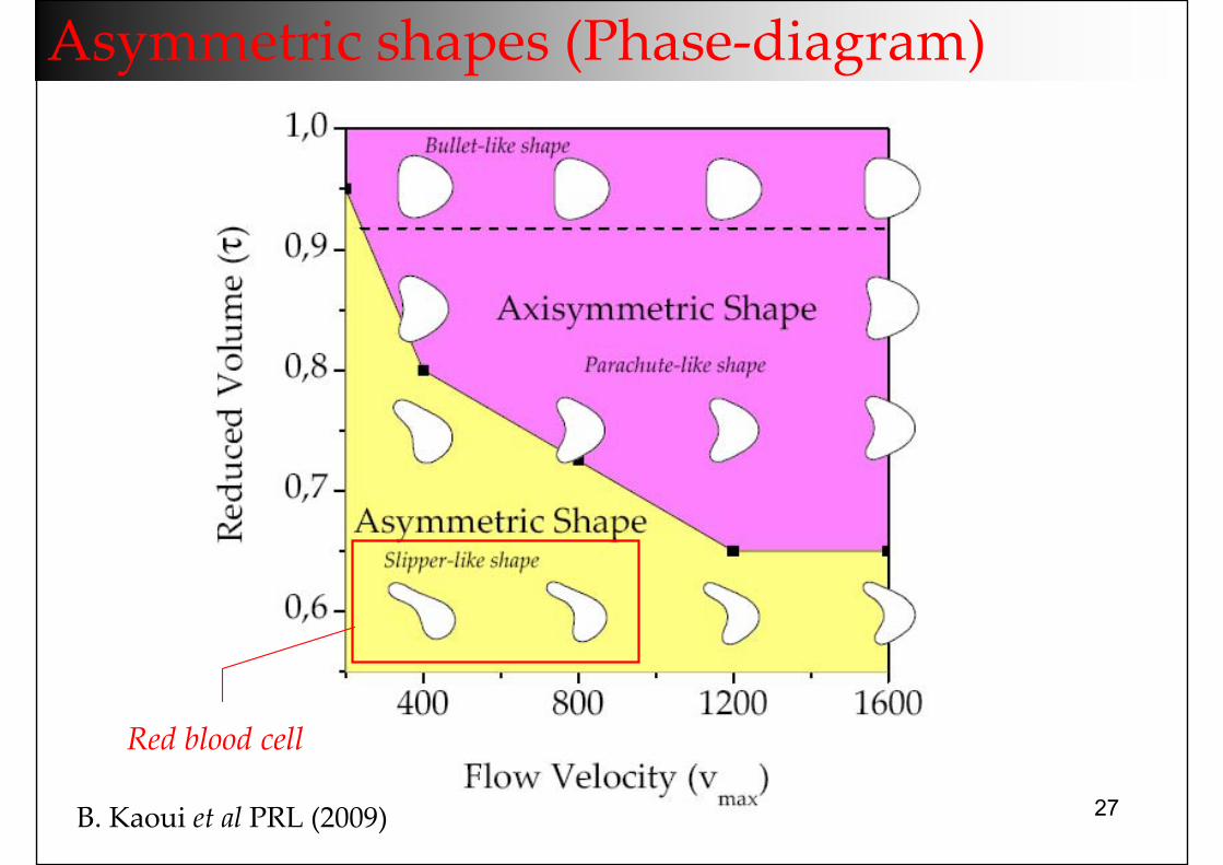
Asymmetric shapes (Phase‐diagram)
Red blood cell
B. Kaoui et al PRL (2009)
28
Vesicle dynamics in confined geometries and in
micro‐fluidic devices
29
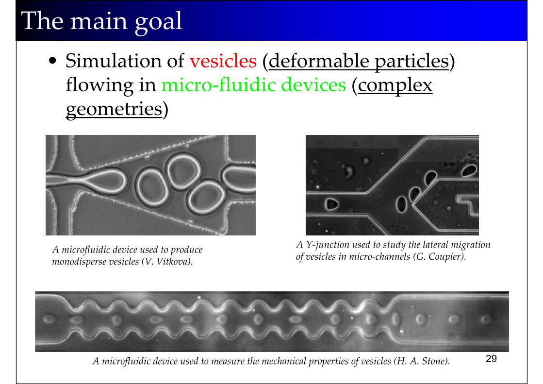
• Simulation of vesicles (deformable particles) flowing in micro‐fluidic devices (complex geometries)
The main goal
A microfluidic device used to produce monodisperse vesicles (V. Vitkova).
A Y‐junction used to study the lateral migration of vesicles in micro‐channels (G. Coupier).
A microfluidic device used to measure the mechanical properties of vesicles (H. A. Stone).
30
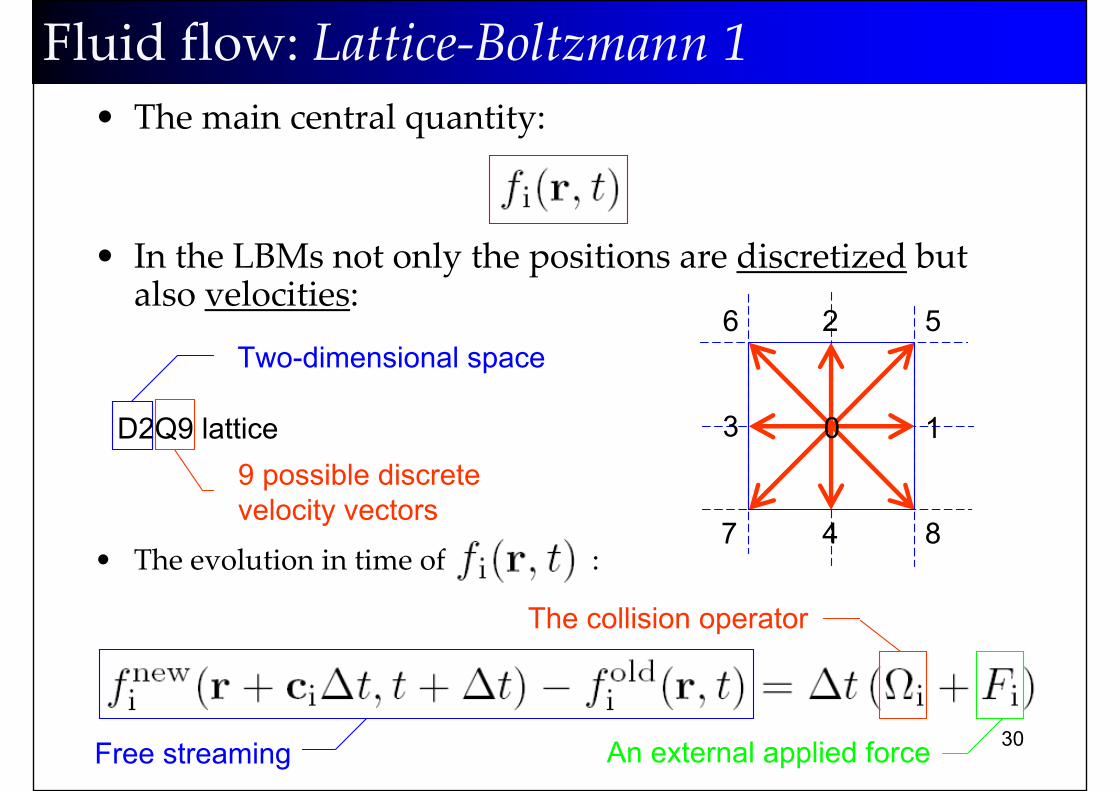
• The main central quantity:
• In the LBMs not only the positions are discretized but also velocities:
• The evolution in time of :
0 1
2
3
4
56
7 8
Two-dimensional space
D2Q9 lattice9 possible discrete velocity vectors
Fluid flow: Lattice‐Boltzmann 1
Free streaming
The collision operator
An external applied force
31
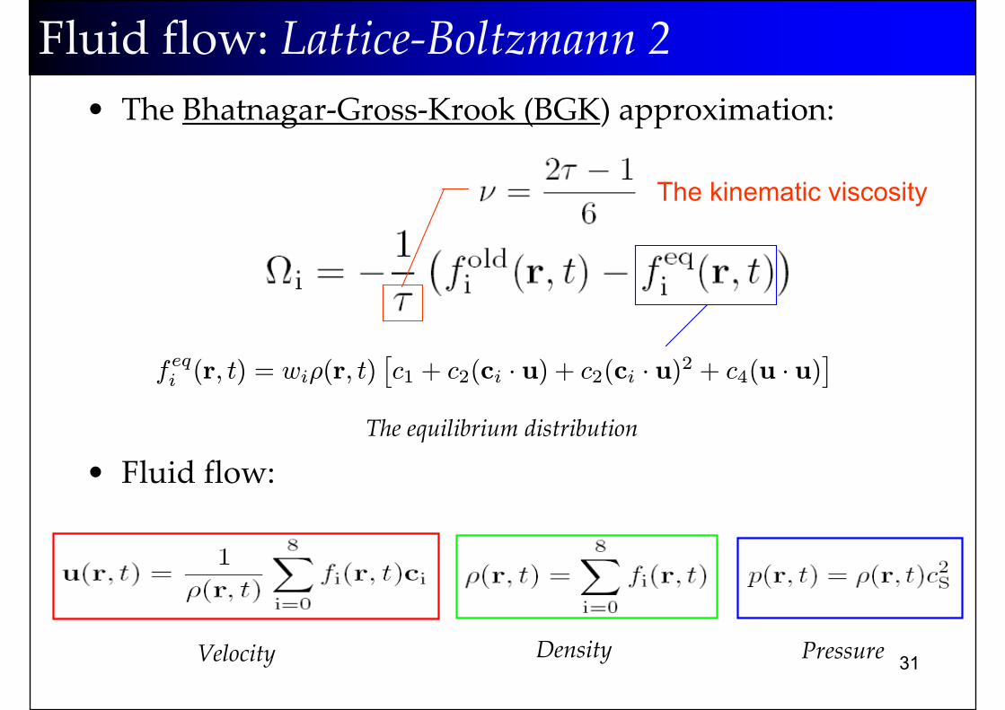
• The Bhatnagar‐Gross‐Krook (BGK) approximation:
• Fluid flow:
The kinematic viscosity
Fluid flow: Lattice‐Boltzmann 2
The equilibrium distribution
feqi (r, t) = wiρ(r, t)£c1 + c2(ci · u) + c2(ci · u)2 + c4(u · u)
¤
Velocity Density Pressure
32
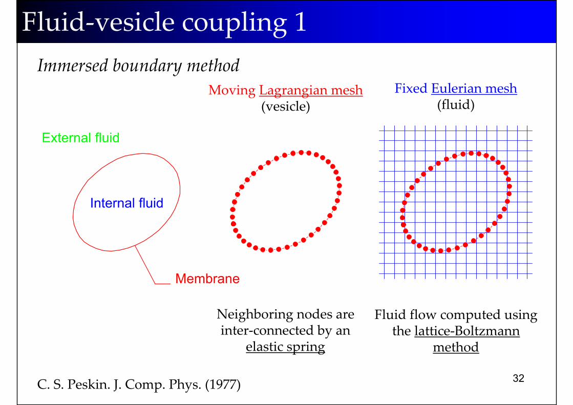
Internal fluid
External fluid
Fluid‐vesicle coupling 1
Moving Lagrangian mesh(vesicle)
Fixed Eulerian mesh(fluid)
Membrane
Fluid flow computed using the lattice‐Boltzmann
method
Neighboring nodes are inter‐connected by an
elastic spring
C. S. Peskin. J. Comp. Phys. (1977)
Immersed boundary method
33
-2-1
01
2
-2-1
01
20
0.2
0.4
0.05
0.1
0.15
0.2
0.25
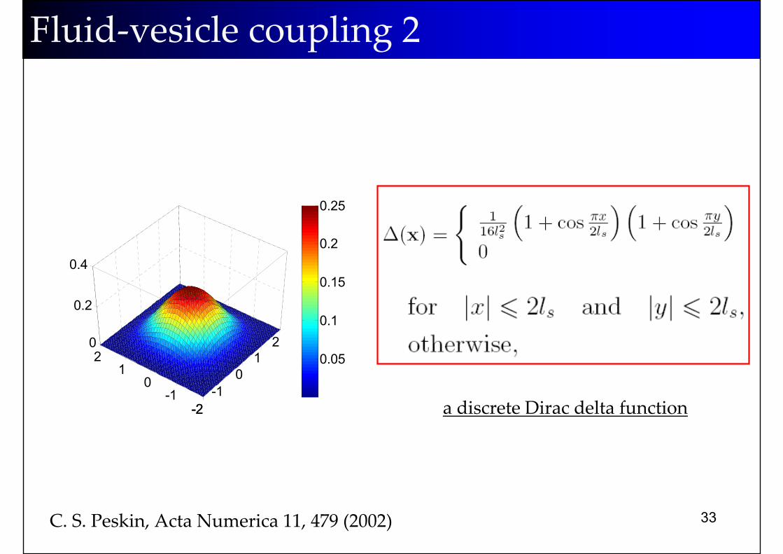
C. S. Peskin, Acta Numerica 11, 479 (2002)
Fluid‐vesicle coupling 2
a discrete Dirac delta function
34
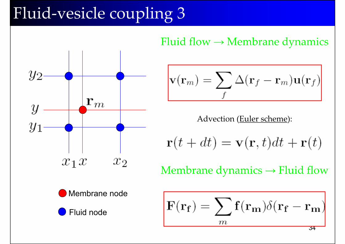
Fluid‐vesicle coupling 3Fluid flow →Membrane dynamics
Advection (Euler scheme):
Membrane node
Fluid node
Membrane dynamics→ Fluid flow
35
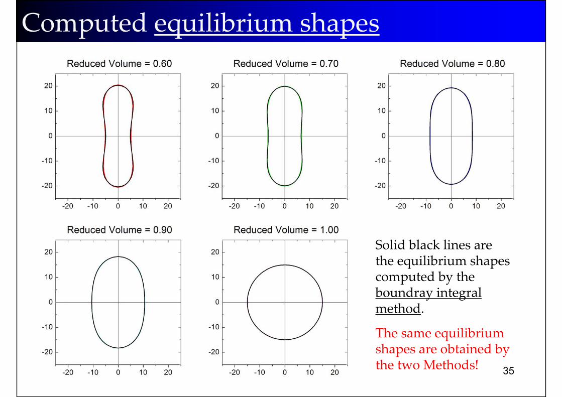
Computed equilibrium shapes
Solid black lines are the equilibrium shapes computed by the boundray integral method.
The same equilibriumshapes are obtained by the two Methods!
36
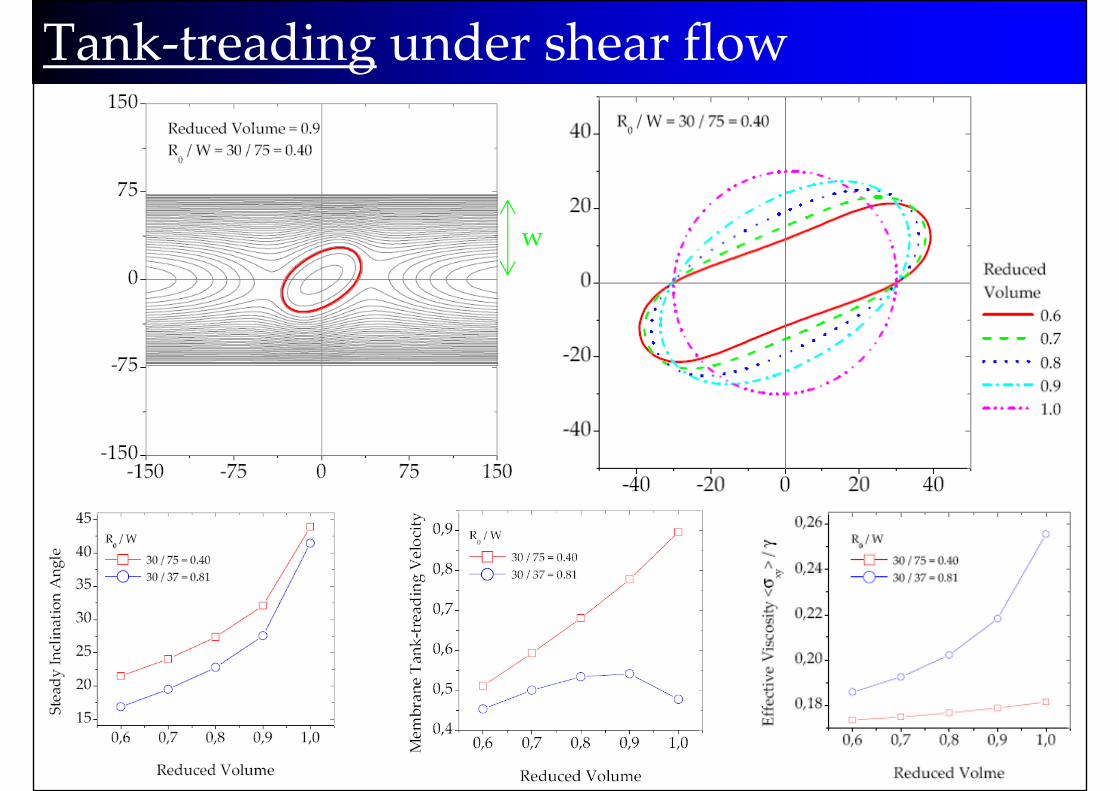
Tank‐treading under shear flow
w
37
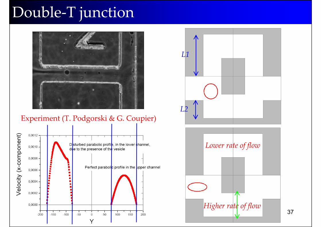
Double‐T junction
Experiment (T. Podgorski & G. Coupier)
LBM Simulation
L1
L2
Higher rate of flow
Lower rate of flow
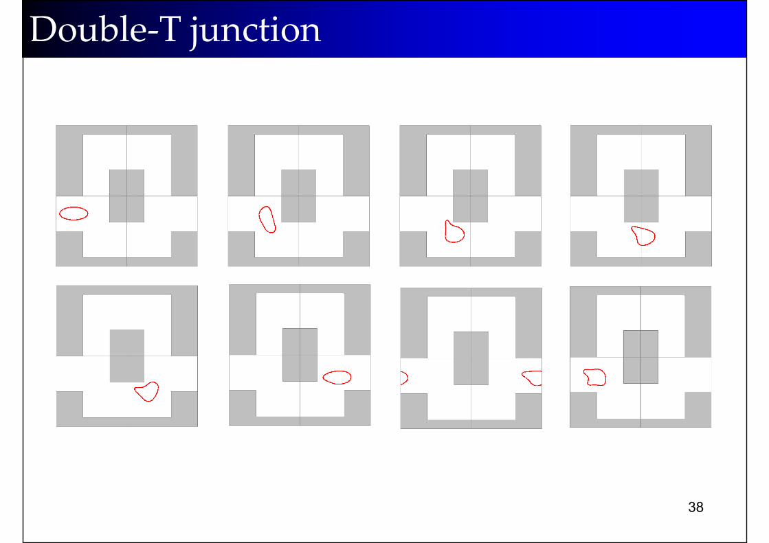
38
Double‐T junction
39
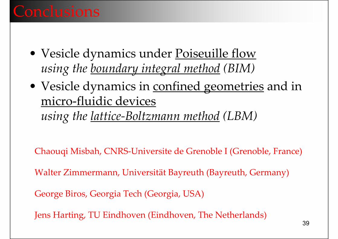
Conclusions
• Vesicle dynamics under Poiseuille flowusing the boundary integral method (BIM)
• Vesicle dynamics in confined geometries and in micro‐fluidic devicesusing the lattice‐Boltzmann method (LBM)
Chaouqi Misbah, CNRS‐Universite de Grenoble I (Grenoble, France)
Walter Zimmermann, Universität Bayreuth (Bayreuth, Germany)
George Biros, Georgia Tech (Georgia, USA)
Jens Harting, TU Eindhoven (Eindhoven, The Netherlands)

40
What am I doing in CASA?
with Federico Toschi & Jan Ten Thije Boonkkamp


![arXiv:1810.04500v1 [physics.bio-ph] 10 Oct 2018orbilu.uni.lu/bitstream/10993/37372/1/Vesicle dynamics in confined... · arXiv:1810.04500v1 [physics.bio-ph] 10 Oct 2018. 2 the vesicle,](https://img.pdfslide.us/doc/110x75/5c6f16b709d3f2254c8bc708/arxiv181004500v1-10-oct-2018orbiluunilubitstream10993373721vesicle.jpg)