Embed Size (px)
Citation preview

Modelling synchrotron radiation using visible light
Helen Lye
ACER
February 2007

Workshop activities
Warning
• Keep direct laser light out of your eyes;
• Point the laser away from you and from other people;
• Look away from bright reflections;
• Set up laser equipment so that the beam is below eye level.


http://www.arpansa.gov.au/pubs/rhs/rhs36.pdf
http://www.vicphysics.org/teachers/photonics.html


Interference and diffraction
• Diffraction: spreading of a wave at right angles to the direction of travel when it passes through a gap or around a narrow object. For visible light, the spreading results in a diffraction pattern of light and dark spots or bands.
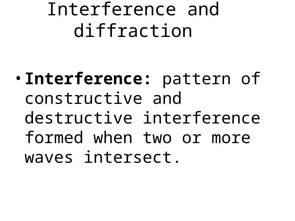
Interference and diffraction
• Interference: pattern of constructive and destructive interference formed when two or more waves intersect.

Examples• Sound wave interference results in louder
and softer sounds in particular positions relative to the sound source.
• Visible light interference results in light and dark regions in particular positions relative to the light source.
• X-ray interference results in high and low intensities of X-rays in particular positions relative to the source.


Single slit and two slits close together
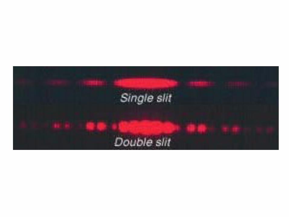

Diffraction of laser light through a vertical opening of decreasing width. Note that as the opening gets narrower, the amount of diffraction in the horizontal direction increases.


Hexagonal hole

Student investigations
Diffraction effects
• Use laser light to observe the diffraction pattern formed by different fibres.
screenobject
laser
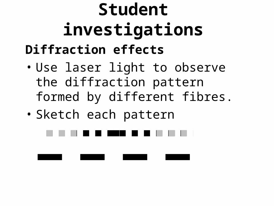
Student investigations
Diffraction effects
• Use laser light to observe the diffraction pattern formed by different fibres.
• Sketch each pattern

Diffraction effects
• take any measurements that you could use to calculate the diameter of each fibre.
•
LengthNumber of dark bands
Distance from object to screen

Diffraction in two dimensions
Two dimensional grids
screenobject
laser


Gauze ribbon (chiffon ribbon) diffraction pattern. STAVCON November 24 2006 Thomas
Cherry lab fourth floor.Red laser level about 2m away;
gauze taped to laser and hanging down.

Two dimensional helix model
• Pair of bolts or screws
• The laser beam must line up with the gap between the threads.
Blu-tack
Two bolts
screen
laser

Two dimensional helix model
• Pair of bolts or screws
• The laser beam must line up with the gap between the threads.

X-ray diffraction pattern of DNA

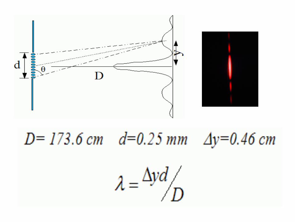
Quantitative
measurements
laser
screenGauze ribbon
Count dark bandsMeasure width of pattern
Measure distance

Diffraction gratings

When light of a single wavelength , like the 632.8nm red light from a helium-neon laser strikes a diffraction grating it is diffracted to each side in multiple orders. Orders 1 and 2 are shown to each side of the direct beam.

While directing the 632.8 nm red beam of a helium-neon laser through a 600 lines/mm diffraction grating, a cloud was formed using liquid nitrogen. You can see the direct beam plus the first and second orders of the diffraction. Another way to visualize the
diffraction is to take a time exposure while sweeping a ground glass through the beams. This "paints in" the beams of the diffracted laser light.
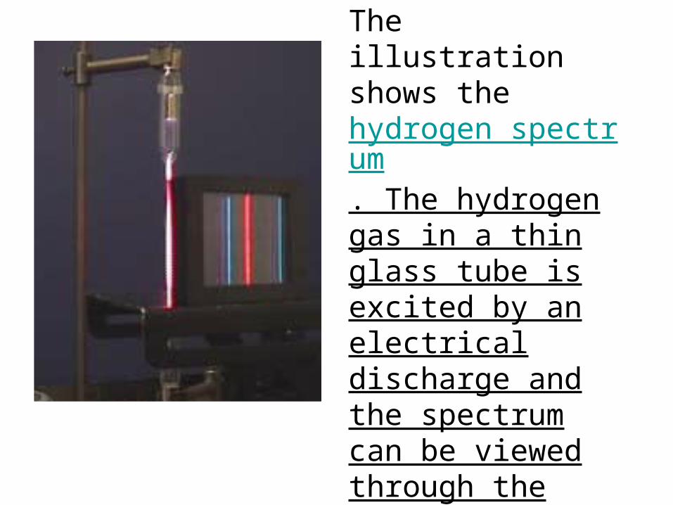
The illustration shows the hydrogen spectrum. The hydrogen gas in a thin glass tube is excited by an electrical discharge and the spectrum can be viewed through the grating.

The tracks of a compact disc act as a diffraction grating, producing a separation of the colors of white light. The nominal track separation on a CD is 1.6 micrometers, corresponding to about 625 tracks per millimeter. For red light of wavelength 600 nm, this would give a first order diffraction maximum at about 22° .


Data
• Measure the angle between the incident laser light and the normal of the CD.
• Measure the angle between the normal to the CD and the n=-1 order and the
• normal and n=1 order.
• Use the grating formula to determine the track spacing on the CD for each set of data

Diffraction pracs from http://www.ssabsa.sa.edu.au/suppo
rt/science/2phy/2phy-menu.htm

Safe laser inspection deviceExplore your toothpaste
Gorazd PlaninˇsiˇcFaculty for Mathematics and Physics, University of Ljubljana,
Sloveniaand
The House of Experiments, Ljubljana, Slovenia
SPECIAL FEATURE: HEALTH AND BEAUTYPHYSICS EDUCATION 41 (4)www.iop.org/journals/physed

Figure 1. What can we find out about the iridescentpieces on the toothpaste package?
Safe Laser Inspection Device made from onehemisphere of a painted Christmas ball.
Diffraction patterns produced by the shiny part of a toothpaste package using red and green laser lightrespectively.