Embed Size (px)
DESCRIPTION
Modelling Simulation and Control of an Active Suspension System
Citation preview
International Journal of Mechanical Engineering and Technology (IJMET), ISSN 0976 – 6340(Print),
ISSN 0976 – 6359(Online), Volume 5, Issue 11, November (2014), pp. 66-75 © IAEME
66
MODELLING SIMULATION AND CONTROL OF AN
ACTIVE SUSPENSION SYSTEM
CHAITANYA KUBER
Department of Mechanical Engineering, Sinhgad College of Engineering,
Pune, Maharashtra, India
ABSTRACT
Conventional passive suspension systems lag in providing the optimum level of performance.
Passive suspensions are a trade-off between the conflicting demands of comfort and control. An
active suspension system provides both comfort and control along with active roll and pitch control
during cornering and braking. Thus it gives a ride that is level and bump free over an incredibly
rough terrain. This paper is a review the active suspension system and the modelling, simulation and
control of an active suspension system in MATLAB/Simulink. The performance of the system is
determined by computer simulation in MATLAB/Simulink. The performance of the system can be
controlled and improved by proper tuning a proportional-integral-derivative (PID) controller. The
simulation study is performed to prove the effectiveness of this control approach and the
performance of the system is compared with the conventional (passive) suspension system.
Keywords: Active suspension system, Control, MATLAB/Simulink, PID controller, Simulation.
1. INTRODUCTION
The main objectives of a suspension system are to prevent the road shocks from being
transmitted to the vehicle, thereby providing a suitable ride and cushioning effect to the occupants,
and to keep the vehicle stable while in motion by providing good road holding (i.e. providing grip for
the driver of vehicle to control its direction) during cornering and braking. But these goals are in
conflict [1]. Body roll is the load transfer of a vehicle towards the outside of a turn (i.e. on the outer
wheels) due to centrifugal force acting upon the car during cornering. Pitching is the tilting of the
vehicle forward when weight is transferred to the front (i.e. during braking), and the tilting of the
vehicle backward when weight is transferred to the rear (i.e. during acceleration). In luxury cars the
suspension is usually designed with an emphasis on comfort, resulting in vehicle rolling and pitching
during turning and braking. Hence, these cars are good at swallowing bumps and providing a plush
ride, but the handling and control is sacrificed. In sports cars the suspension is usually designed with
INTERNATIONAL JOURNAL OF MECHANICAL ENGINEERING AND
TECHNOLOGY (IJMET)
ISSN 0976 – 6340 (Print)
ISSN 0976 – 6359 (Online)
Volume 5, Issue 11, November (2014), pp. 66-75
© IAEME: www.iaeme.com/IJMET.asp
Journal Impact Factor (2014): 7.5377 (Calculated by GISI)
www.jifactor.com
IJMET
© I A E M E
International Journal of Mechanical Engineering and Technology (IJMET), ISSN 0976 – 6340(Print),
ISSN 0976 – 6359(Online), Volume 5, Issue 11, November (2014), pp. 66-75 © IAEME
67
an emphasis on control i.e. the suspension is designed to reduce roll and pitch, but comfort and ride
quality is sacrificed. Hence, conventional suspensions are a trade-off between comfort and control of
a vehicle. In order to provide both ride quality (comfort) and vehicle stability(control) active
suspension systems have been developed.
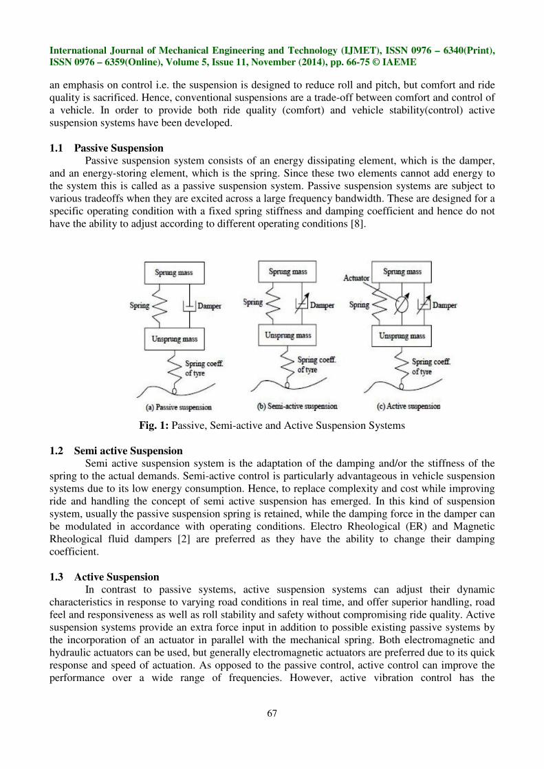
1.1 Passive Suspension
Passive suspension system consists of an energy dissipating element, which is the damper,
and an energy-storing element, which is the spring. Since these two elements cannot add energy to
the system this is called as a passive suspension system. Passive suspension systems are subject to
various tradeoffs when they are excited across a large frequency bandwidth. These are designed for a
specific operating condition with a fixed spring stiffness and damping coefficient and hence do not
have the ability to adjust according to different operating conditions [8].
Fig. 1: Passive, Semi-active and Active Suspension Systems
1.2 Semi active Suspension
Semi active suspension system is the adaptation of the damping and/or the stiffness of the
spring to the actual demands. Semi-active control is particularly advantageous in vehicle suspension
systems due to its low energy consumption. Hence, to replace complexity and cost while improving
ride and handling the concept of semi active suspension has emerged. In this kind of suspension
system, usually the passive suspension spring is retained, while the damping force in the damper can
be modulated in accordance with operating conditions. Electro Rheological (ER) and Magnetic
Rheological fluid dampers [2] are preferred as they have the ability to change their damping
coefficient.
1.3 Active Suspension
In contrast to passive systems, active suspension systems can adjust their dynamic
characteristics in response to varying road conditions in real time, and offer superior handling, road
feel and responsiveness as well as roll stability and safety without compromising ride quality. Active
suspension systems provide an extra force input in addition to possible existing passive systems by
the incorporation of an actuator in parallel with the mechanical spring. Both electromagnetic and
hydraulic actuators can be used, but generally electromagnetic actuators are preferred due to its quick
response and speed of actuation. As opposed to the passive control, active control can improve the
performance over a wide range of frequencies. However, active vibration control has the
International Journal of Mechanical Engineering and Technology (IJMET), ISSN 0976 – 6340(Print),
ISSN 0976 – 6359(Online), Volume 5, Issue 11, November (2014), pp. 66-75 © IAEME
68
disadvantages of complexity and high energy consumption. This system is explained in detail in the
next section.
The outline of the paper is as follows. Section 2 gives a detailed description of the active
suspension system. Quarter car test setup is discussed in section 3, which is the basis for suspension
system modelling that is discussed in section 4. Section 5 and section 6 deal with the modelling and
control of the suspension system respectively. Section 7 compares the performance of the active and
passive suspension systems. Conclusion is presented in section 8.
2. ACTIVE SUSPENSION SYSTEM
The active suspension system works as a closed loop control system. The active suspension
system consists of four important components viz.
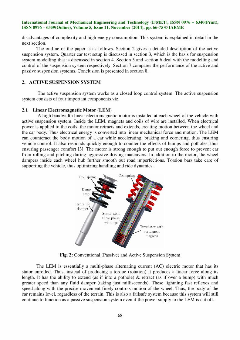
2.1 Linear Electromagnetic Motor (LEM)
A high bandwidth linear electromagnetic motor is installed at each wheel of the vehicle with
active suspension system. Inside the LEM, magnets and coils of wire are installed. When electrical
power is applied to the coils, the motor retracts and extends, creating motion between the wheel and
the car body. Thus electrical energy is converted into linear mechanical force and motion. The LEM
can counteract the body motion of a car while accelerating, braking and cornering, thus ensuring
vehicle control. It also responds quickly enough to counter the effects of bumps and potholes, thus
ensuring passenger comfort [3]. The motor is strong enough to put out enough force to prevent car
from rolling and pitching during aggressive driving maneuvers. In addition to the motor, the wheel
dampers inside each wheel hub further smooth out road imperfections. Torsion bars take care of
supporting the vehicle, thus optimizing handling and ride dynamics.
Fig. 2: Conventional (Passive) and Active Suspension System
The LEM is essentially a multi-phase alternating current (AC) electric motor that has its
stator unrolled. Thus, instead of producing a torque (rotation) it produces a linear force along its
length. It has the ability to extend (as if into a pothole) & retract (as if over a bump) with much
greater speed than any fluid damper (taking just milliseconds). These lightning fast reflexes and
speed along with the precise movement finely controls motion of the wheel. Thus, the body of the
car remains level, regardless of the terrain. This is also a failsafe system because this system will still
continue to function as a passive suspension system even if the power supply to the LEM is cut off.
International Journal of Mechanical Engineering and Technology (IJMET), ISSN 0976 – 6340(Print),
ISSN 0976 – 6359(Online), Volume 5, Issue 11, November (2014), pp. 66-75 © IAEME
69
2.2 Sensors
A sensor measures a physical parameter (vertical displacement, acceleration and velocity)
and decodes it into an electrical signal. In this system three types of sensors are used. The sensor
measurements are used to instantaneously counteract the road forces. The sprung mass acceleration
sensor gives a direct measure of comfort of the vehicle. The suspension travel sensor gives direct
measure of suspension travel, which is the measure of distance from the bottom of the suspension
stroke (when the vehicle is on a jack and the wheel hangs freely) to the top of the suspension stroke
(when the vehicle's wheel can no longer travel in an upward direction toward the vehicle) This
sensor is aligned with the passive spring and damper and hence the stroke can be measured directly
[4]. The unsprung mass acceleration sensor is installed to estimate the state of the tyre since it is not
possible to measure the tyre compression directly. Thus, this set of three sensors provides all the
information needed for the operation of the system.
2.3 Power Amplifier
A bidirectional power amplifier sends the power to the LEM during extension and the LEM
returns the power to the amplifier during retraction. The electrical power is delivered to the LEM by
a power amplifier in response to signals from the control algorithms. The system uses compressive
force to recover the energy or power, and store it either in the engine battery or in some other
external storage device. Thus, when the suspension encounters a pothole, power is used to extend the
motor and isolate the vehicle’s occupants from the disturbance. On the far side of the pothole, the
motor operates as a generator and returns the power back through the amplifier. This regenerative
action results in a very efficient suspension system design.
2.4 Control Algorithms
The sensor measurements are used by the control algorithms and they send command to the
power amplifiers which in turn operate the LEM. These electrical signals from the sensors are
processed by the PID and it generates a control signal which controls the action of the actuator for
fine response in real time.
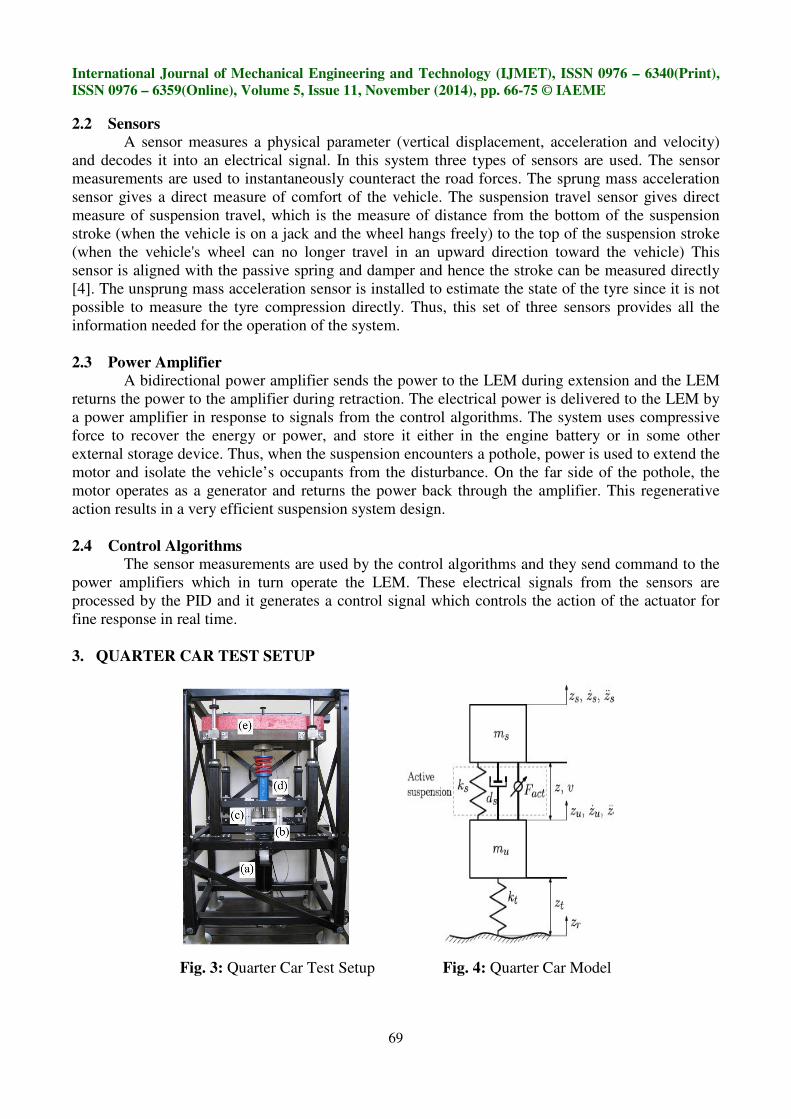
3. QUARTER CAR TEST SETUP
Fig. 3: Quarter Car Test Setup Fig. 4: Quarter Car Model
International Journal of Mechanical Engineering and Technology (IJMET), ISSN 0976 – 6340(Print),
ISSN 0976 – 6359(Online), Volume 5, Issue 11, November (2014), pp. 66-75 © IAEME
70
The quarter car model suspension system consists of one-fourth of the body mass,
suspension components and one wheel. The on road measurements are reproduced on a quarter car
test setup. In Fig. 3, the alphabets represent different components [5]. Here, 'a' represents the road
shaker which performs the road excitations, 'b' represents the coil spring representing the tyre
stiffness, 'c' represents the unsprung mass, 'd' represents the active suspension system which connects
sprung mass and the unsprung mass, and 'e' represents the sprung mass. This is also represented
symbolically in Fig 4. Quarter car models simplify the analysis and represent most of the features of
the full scale model.
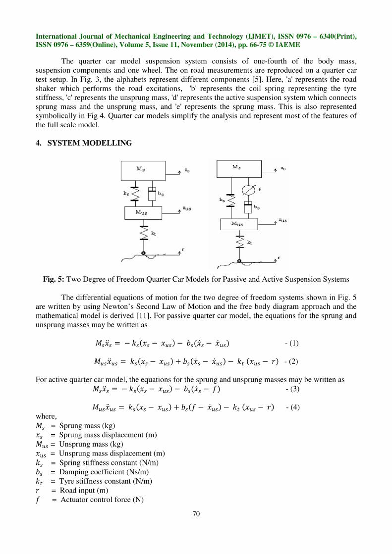
4. SYSTEM MODELLING
Fig. 5: Two Degree of Freedom Quarter Car Models for Passive and Active Suspension Systems
The differential equations of motion for the two degree of freedom systems shown in Fig. 5
are written by using Newton’s Second Law of Motion and the free body diagram approach and the
mathematical model is derived [11]. For passive quarter car model, the equations for the sprung and
unsprung masses may be written as
����� =−���� −��� −��� � −� �� - (1)
����� =���� −��� + ��� � −� �� −�� �� − �� - (2)
For active quarter car model, the equations for the sprung and unsprung masses may be written as
����� =−���� −��� −��� � − �� - (3)
����� =���� −��� + ��� −� �� −�� �� − �� - (4)
where,
�� = Sprung mass (kg)
�� = Sprung mass displacement (m)
�� = Unsprung mass (kg)
�� = Unsprung mass displacement (m)
�� = Spring stiffness constant (N/m)
�� = Damping coefficient (Ns/m)
�� = Tyre stiffness constant (N/m)
� = Road input (m)
� = Actuator control force (N)
International Journal of Mechanical Engineering and Technology (IJMET), ISSN 0976 – 6340(Print),
ISSN 0976 – 6359(Online), Volume 5, Issue 11, November (2014), pp. 66-75 © IAEME
71
In the above representation of the passive and active suspension systems, tyre is modelled as
a linear spring without damping. The road input (r) is considered as the disturbance signal. The
actuator control force (f) is introduced in the system by the LEM, between the body mass (sprung
mass) and the wheel mass (unsprung mass).
5. SIMULATION
Mathematical modelling is transformed into a computer simulation model and
MATLAB/Simulink is used for the simulation. Simulink is a versatile interface that can handle
various types of controllers easily. It helps in dynamic performance analysis of a system by
construction of a basic suspension model along with the implementation a controller integrated
within the system [6]. The Simulink library is utilized and the logic is developed according to the
mathematical model to simulate the system in Simulink. The passive suspension system model in
Simulink is based on the equation (1) and (2). This is an open loop system with no feedback element
for appropriate adjustment of the parameters. The active suspension system model in Simulink is
based on the equation (3) and (4). In this system, the actuator force is controlled by the PID, thus
involving a feedback loop.
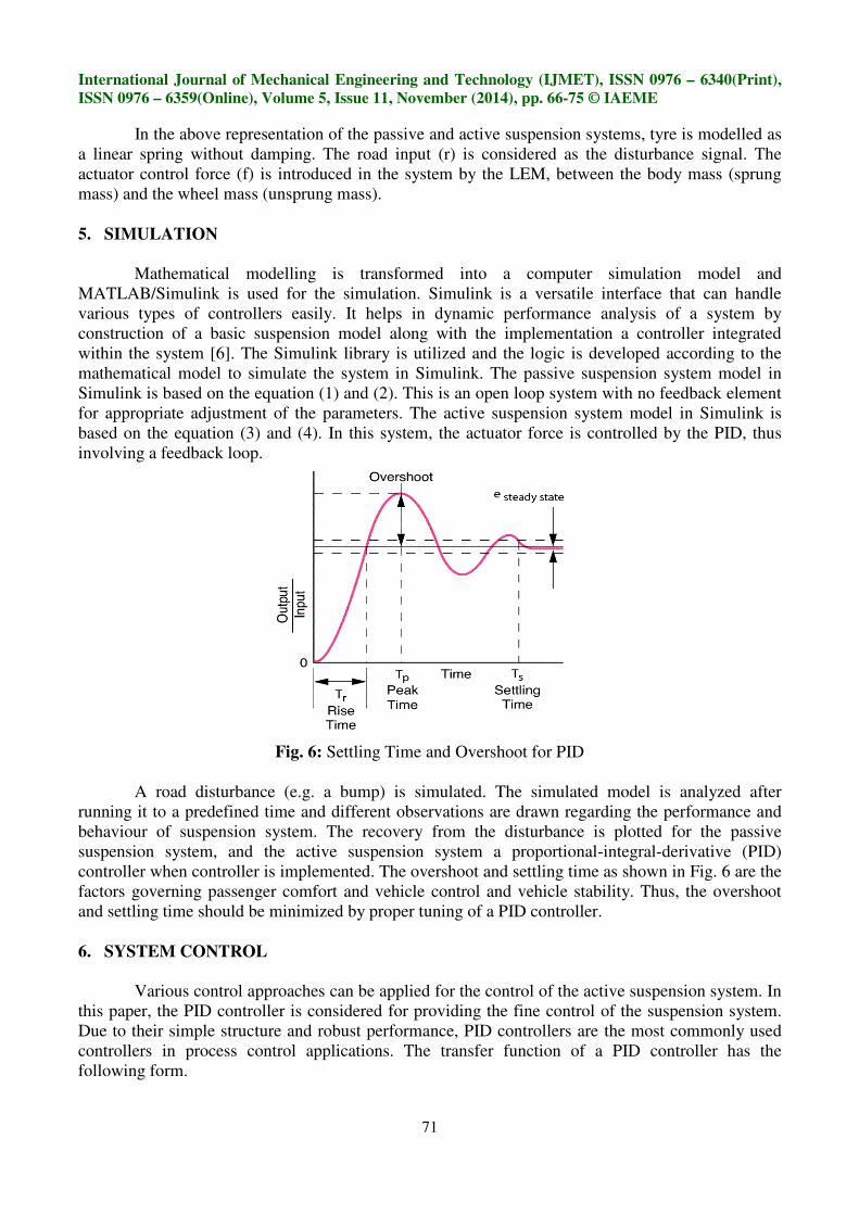
Fig. 6: Settling Time and Overshoot for PID
A road disturbance (e.g. a bump) is simulated. The simulated model is analyzed after
running it to a predefined time and different observations are drawn regarding the performance and
behaviour of suspension system. The recovery from the disturbance is plotted for the passive
suspension system, and the active suspension system a proportional-integral-derivative (PID)
controller when controller is implemented. The overshoot and settling time as shown in Fig. 6 are the
factors governing passenger comfort and vehicle control and vehicle stability. Thus, the overshoot
and settling time should be minimized by proper tuning of a PID controller.
6. SYSTEM CONTROL
Various control approaches can be applied for the control of the active suspension system. In
this paper, the PID controller is considered for providing the fine control of the suspension system.
Due to their simple structure and robust performance, PID controllers are the most commonly used
controllers in process control applications. The transfer function of a PID controller has the
following form.
International Journal of Mechanical Engineering and Technology (IJMET), ISSN 0976 – 6340(Print),
ISSN 0976 – 6359(Online), Volume 5, Issue 11, November (2014), pp. 66-75 © IAEME
72
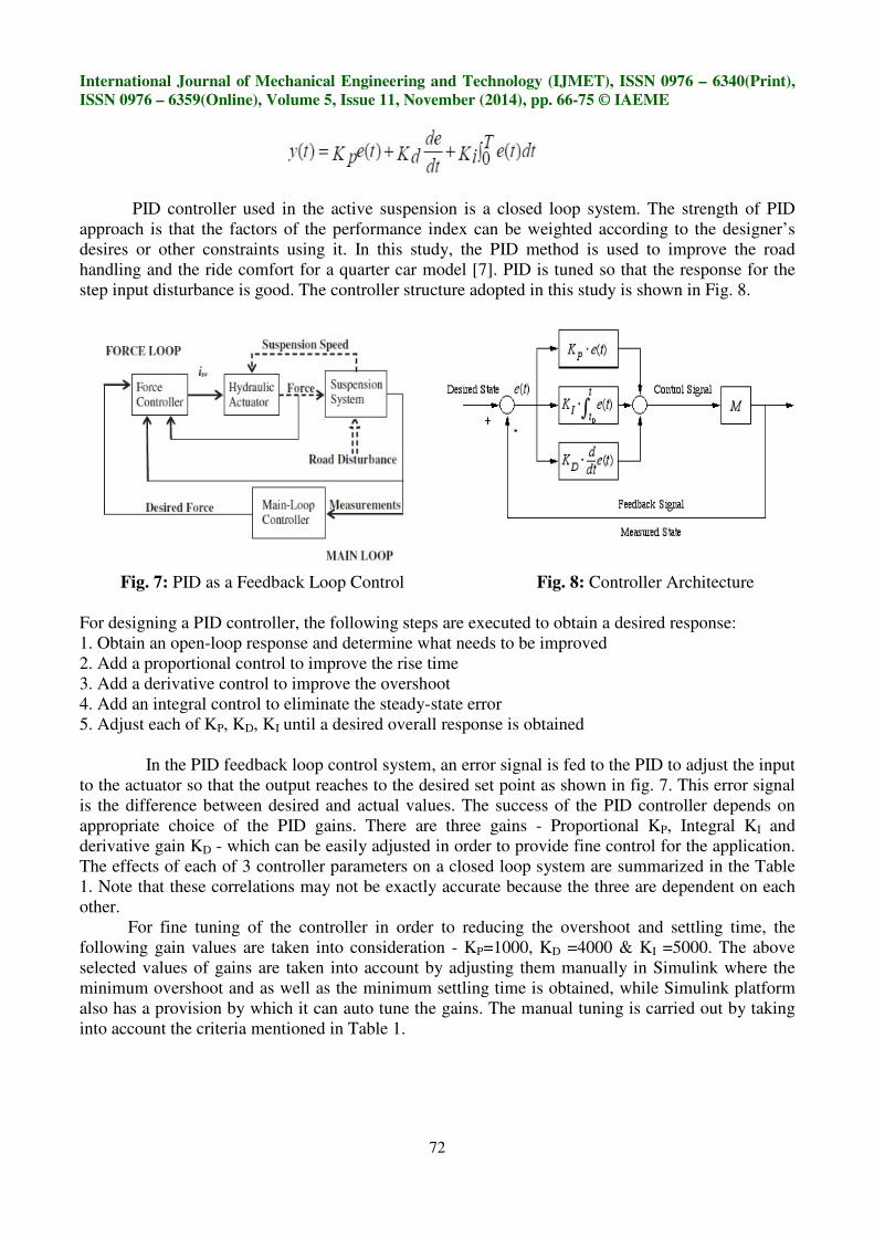
PID controller used in the active suspension is a closed loop system. The strength of PID
approach is that the factors of the performance index can be weighted according to the designer’s
desires or other constraints using it. In this study, the PID method is used to improve the road
handling and the ride comfort for a quarter car model [7]. PID is tuned so that the response for the
step input disturbance is good. The controller structure adopted in this study is shown in Fig. 8.
Fig. 7: PID as a Feedback Loop Control Fig. 8: Controller Architecture
For designing a PID controller, the following steps are executed to obtain a desired response:
1. Obtain an open-loop response and determine what needs to be improved
2. Add a proportional control to improve the rise time
3. Add a derivative control to improve the overshoot
4. Add an integral control to eliminate the steady-state error
5. Adjust each of KP, KD, KI until a desired overall response is obtained
In the PID feedback loop control system, an error signal is fed to the PID to adjust the input
to the actuator so that the output reaches to the desired set point as shown in fig. 7. This error signal
is the difference between desired and actual values. The success of the PID controller depends on
appropriate choice of the PID gains. There are three gains - Proportional KP, Integral KI and
derivative gain KD - which can be easily adjusted in order to provide fine control for the application.
The effects of each of 3 controller parameters on a closed loop system are summarized in the Table
1. Note that these correlations may not be exactly accurate because the three are dependent on each
other.
For fine tuning of the controller in order to reducing the overshoot and settling time, the
following gain values are taken into consideration - KP=1000, KD =4000 & KI =5000. The above
selected values of gains are taken into account by adjusting them manually in Simulink where the
minimum overshoot and as well as the minimum settling time is obtained, while Simulink platform
also has a provision by which it can auto tune the gains. The manual tuning is carried out by taking
into account the criteria mentioned in Table 1.
International Journal of Mechanical Engineering and Technology (IJMET), ISSN 0976 – 6340(Print),
ISSN 0976 – 6359(Online), Volume 5, Issue 11, November (2014), pp. 66-75 © IAEME
73
Table No. 1: Gain Variation with Different Factors for Tuning of PID
Controller Response Rise Time Overshoot Settling Time Steady State Error
KP Decrease Increase Small Change Decrease
KI Decrease Increase Increase Eliminate
KD Small Change Decrease Decrease Small Change
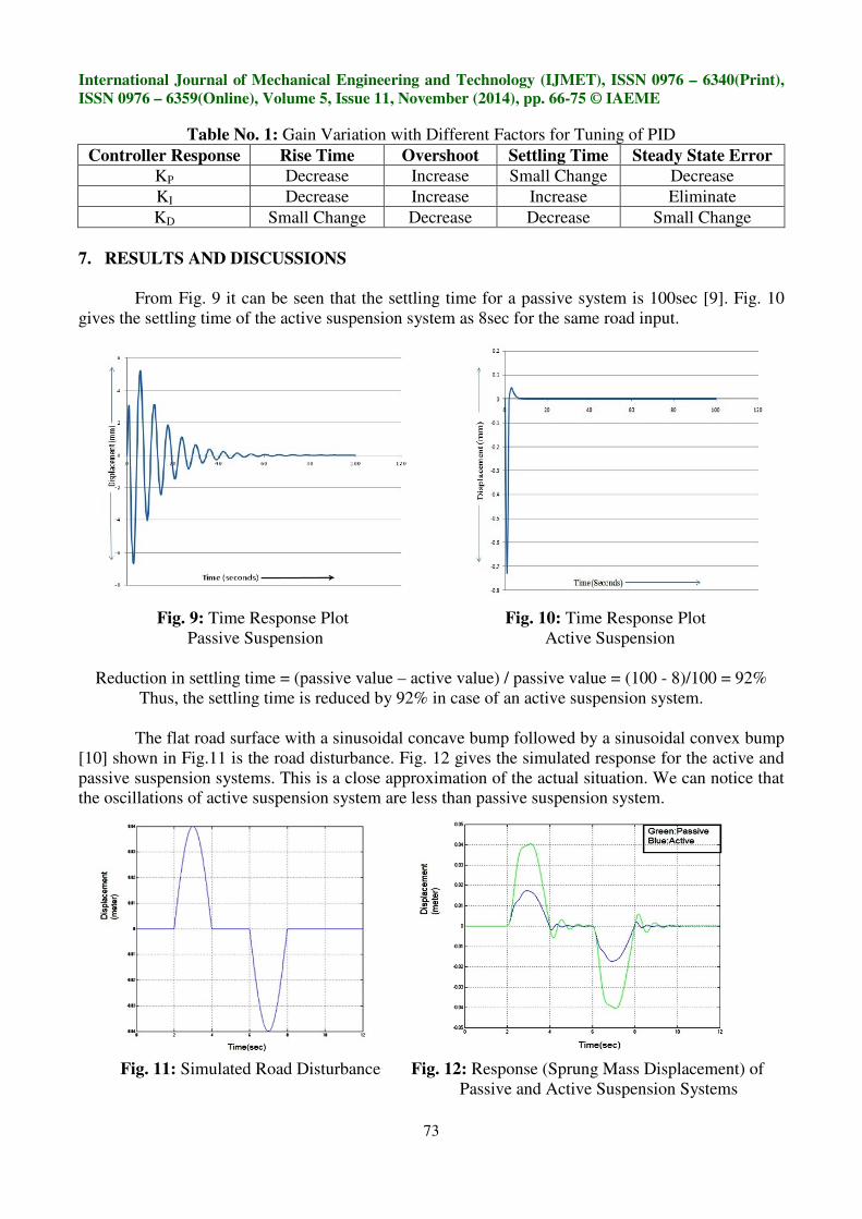
7. RESULTS AND DISCUSSIONS
From Fig. 9 it can be seen that the settling time for a passive system is 100sec [9]. Fig. 10
gives the settling time of the active suspension system as 8sec for the same road input.
Fig. 9: Time Response Plot Fig. 10: Time Response Plot
Passive Suspension Active Suspension
Reduction in settling time = (passive value – active value) / passive value = (100 - 8)/100 = 92%
Thus, the settling time is reduced by 92% in case of an active suspension system.
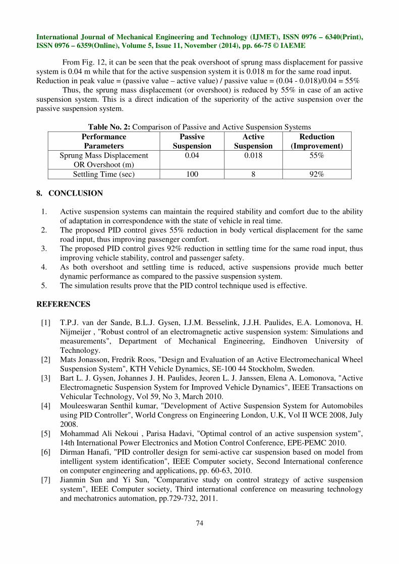
The flat road surface with a sinusoidal concave bump followed by a sinusoidal convex bump
[10] shown in Fig.11 is the road disturbance. Fig. 12 gives the simulated response for the active and
passive suspension systems. This is a close approximation of the actual situation. We can notice that
the oscillations of active suspension system are less than passive suspension system.
Fig. 11: Simulated Road Disturbance Fig. 12: Response (Sprung Mass Displacement) of
Passive and Active Suspension Systems
International Journal of Mechanical Engineering and Technology (IJMET), ISSN 0976 – 6340(Print),
ISSN 0976 – 6359(Online), Volume 5, Issue 11, November (2014), pp. 66-75 © IAEME
74
From Fig. 12, it can be seen that the peak overshoot of sprung mass displacement for passive
system is 0.04 m while that for the active suspension system it is 0.018 m for the same road input.
Reduction in peak value = (passive value – active value) / passive value = (0.04 - 0.018)/0.04 = 55%
Thus, the sprung mass displacement (or overshoot) is reduced by 55% in case of an active
suspension system. This is a direct indication of the superiority of the active suspension over the
passive suspension system.
Table No. 2: Comparison of Passive and Active Suspension Systems
Performance
Parameters
Passive
Suspension
Active
Suspension
Reduction
(Improvement)
Sprung Mass Displacement
OR Overshoot (m)
0.04 0.018 55%
Settling Time (sec) 100 8 92%
8. CONCLUSION
1. Active suspension systems can maintain the required stability and comfort due to the ability
of adaptation in correspondence with the state of vehicle in real time.
2. The proposed PID control gives 55% reduction in body vertical displacement for the same
road input, thus improving passenger comfort.
3. The proposed PID control gives 92% reduction in settling time for the same road input, thus
improving vehicle stability, control and passenger safety.
4. As both overshoot and settling time is reduced, active suspensions provide much better
dynamic performance as compared to the passive suspension system.
5. The simulation results prove that the PID control technique used is effective.
REFERENCES
[1] T.P.J. van der Sande, B.L.J. Gysen, I.J.M. Besselink, J.J.H. Paulides, E.A. Lomonova, H.
Nijmeijer , "Robust control of an electromagnetic active suspension system: Simulations and
measurements", Department of Mechanical Engineering, Eindhoven University of
Technology.
[2] Mats Jonasson, Fredrik Roos, "Design and Evaluation of an Active Electromechanical Wheel
Suspension System", KTH Vehicle Dynamics, SE-100 44 Stockholm, Sweden.
[3] Bart L. J. Gysen, Johannes J. H. Paulides, Jeoren L. J. Janssen, Elena A. Lomonova, "Active
Electromagnetic Suspension System for Improved Vehicle Dynamics", IEEE Transactions on
Vehicular Technology, Vol 59, No 3, March 2010.
[4] Mouleeswaran Senthil kumar, "Development of Active Suspension System for Automobiles
using PID Controller", World Congress on Engineering London, U.K, Vol II WCE 2008, July
2008.
[5] Mohammad Ali Nekoui , Parisa Hadavi, "Optimal control of an active suspension system",
14th International Power Electronics and Motion Control Conference, EPE-PEMC 2010.
[6] Dirman Hanafi, "PID controller design for semi-active car suspension based on model from
intelligent system identification", IEEE Computer society, Second International conference
on computer engineering and applications, pp. 60-63, 2010.
[7] Jianmin Sun and Yi Sun, "Comparative study on control strategy of active suspension
system", IEEE Computer society, Third international conference on measuring technology
and mechatronics automation, pp.729-732, 2011.
International Journal of Mechanical Engineering and Technology (IJMET), ISSN 0976 – 6340(Print),
ISSN 0976 – 6359(Online), Volume 5, Issue 11, November (2014), pp. 66-75 © IAEME
75
[8] P. Sathishkumar, J. Jancirani, Dennie john, S. manikandan, "Mathematical modelling and
simulation quarter car vehicle suspension", International Conference on Engineering
Technology and Science-(ICETS’14), Volume 3, Special Issue 1, February 2014.
[9] Mohd. Avesh, Rajeev Srivastava, "Modelling Simulation and Control of active suspension
system in Matlab Simulink environment", 978-1-4673-0455-9/12/, 2012 IEEE.
[10] Sayel M. Fayyad, "Constructing Control System for Active Suspension System",
Contemporary Engineering Sciences, Vol. 5, 2012, no. 4, 189 - 200.
[11] Padraig Dowds, Aidan O'Dwyer, "Modelling and control of a suspension system for vehicle
applications", Dublin Institute of Technology, 2005-01-01, Conference Papers, School of
Electrical Engineering Systems.