Embed Size (px)
Citation preview
Available online at www.sciencedirect.com
202 (2008) 4458–4464www.elsevier.com/locate/surfcoat
Surface & Coatings Technology
Modelling of the plasma spray process with liquid feedstock injection
Cécile Marchand, Armelle Vardelle⁎, Gilles Mariaux, Pierre Lefort
ENSIL, 16 rue Atlantis, 87068 Limoges cedex, France
Available online 10 April 2008
Abstract
The feasibility of liquid precursor plasma spray techniques has already been demonstrated and coatings are manufactured with a large spectrumof textures and properties. However, a key to success is the ability (i) to produce, and maintain, a stable spray pattern with consistent trajectories,once the optimum operating conditions are determined for producing a coating with a specific microstructure; and (ii) to maximize the depositefficiency. Realistic models of the spray process help to augment the understanding of a process that involves complex and intricate phenomenaand to achieve these objectives. In particular, they make it possible to investigate the effect of the process operating conditions on specificphenomena. This paper deals with the effect of the fluctuations of the plasma jet on liquid feedstock injection and droplet possible break-upregimes in the gas flow.© 2008 Elsevier B.V. All rights reserved.
Keywords: Plasma spraying; Liquid precursor; Modeling; Transient simulation
1. Introduction
Even though the plasma spray technology involves highlycomplex and time-dependent phenomena, it can be consideredas a simple industrial process as it can operate in openatmosphere and involves only three main elements: the plasmatorch, the material feeder and the part to be covered. Hence, thetechnique provides an appealing opportunity for the manufac-turing of nano-structured coatings, which is a frontline andactive research field today.
However, the powders generally used in plasma sprayinghave a particle size distribution ranging between 5 and 100 µmand, the lamellae that are formed by the impact of the moltenparticles on the substrate and constitute the basic elements of theplasma-sprayed coating, exhibit thickness in the micrometerrange. Therefore, specific feedstock or spray procedures have tobe employed to produce nanostructured coatings. The maincurrent directions are based on the utilization of nanostructuredagglomerated powders [1] or liquid feedstock [2,3]. The liquidinjected in the plasma flow may be either a suspension of nano-or micro-sized particles in aqueous or organic solvents with
⁎ Corresponding author. Tel.: +33 5 55 42 36 84; fax: +33 5 55 42 36 80.E-mail address: [email protected] (A. Vardelle).
0257-8972/$ - see front matter © 2008 Elsevier B.V. All rights reserved.doi:10.1016/j.surfcoat.2008.04.027
dispersing agents, or a solution metal salts, organometallicprecursors or liquid metal precursors in a solvent. Both types offeedstock will produce finely-structured coatings and make itpossible to get dense or porous coatings by controlling thetrajectories and treatment of the droplets in the plasma flow.
The plasma spray process can be divided in four sub-systems: plasma jet formation, feedstock injection, plasma–droplet interactions and substrate–droplet interactions. Theoperation of the two first sub-systems will be similar forsolutions and suspensions while the treatment of the droplets inthe plasma flow and the morphology of the resulting lamellaewill differ. However, a common feature of liquid feedstock usedin plasma spraying is their low density (∼1000 kg/m3) ascompared to that of materials in the form of powders. Becauseof this low density and possible fragmentation of dropletsbefore or at injection, the liquid penetration into the plasma jet istrickier and more sensitive to any fluctuation in the process,than in the case of powder particles [4].
As the coating microstructure is inseparable from theelaboration process conditions, the time-dependent models ofthe process are becoming a tool to better understand the intricateand intertwined interactions between the operating conditions ofthe process, such as the fluctuating plasma flow and the injectedliquid. To provide reasonably good predictions, such models
4459C. Marchand et al. / Surface & Coatings Technology 202 (2008) 4458–4464
must combine an accurate model of the plasma jet itself with arealistic description of particle injection and behaviour in theplasma flow. Although numerous mathematical models of theatmospheric plasma spray process have been proposed in theliterature in the last 20 years, very few deal with the liquidplasma spray process and none of them take into account thetime-dependent phenomena when using liquid precursor.
This paper will first briefly discuss the distinctive features ofthe models of plasma spray process with liquid feedstock, it willthen present the effect of plasma jet fluctuations on dropletinjection and will finally examine the droplet break-up regimesin the plasma flow.
2. Distinctive features of the models of the plasma sprayprocess with liquid feedstock
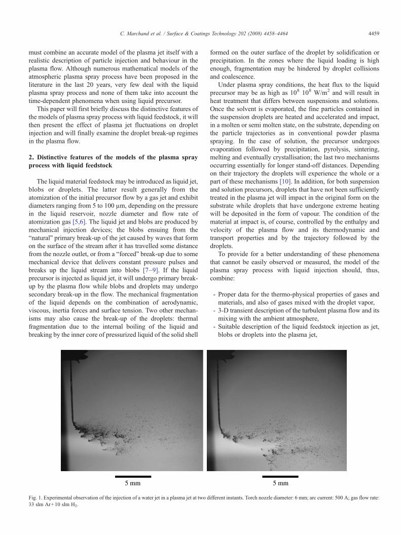
The liquid material feedstock may be introduced as liquid jet,blobs or droplets. The latter result generally from theatomization of the initial precursor flow by a gas jet and exhibitdiameters ranging from 5 to 100 µm, depending on the pressurein the liquid reservoir, nozzle diameter and flow rate ofatomization gas [5,6]. The liquid jet and blobs are produced bymechanical injection devices; the blobs ensuing from the“natural” primary break-up of the jet caused by waves that formon the surface of the stream after it has travelled some distancefrom the nozzle outlet, or from a “forced” break-up due to somemechanical device that delivers constant pressure pulses andbreaks up the liquid stream into blobs [7–9]. If the liquidprecursor is injected as liquid jet, it will undergo primary break-up by the plasma flow while blobs and droplets may undergosecondary break-up in the flow. The mechanical fragmentationof the liquid depends on the combination of aerodynamic,viscous, inertia forces and surface tension. Two other mechan-isms may also cause the break-up of the droplets: thermalfragmentation due to the internal boiling of the liquid andbreaking by the inner core of pressurized liquid of the solid shell
Fig. 1. Experimental observation of the injection of a water jet in a plasma jet at two d33 slm Ar+10 slm H2.
formed on the outer surface of the droplet by solidification orprecipitation. In the zones where the liquid loading is highenough, fragmentation may be hindered by droplet collisionsand coalescence.
Under plasma spray conditions, the heat flux to the liquidprecursor may be as high as 108 108 W/m2 and will result inheat treatment that differs between suspensions and solutions.Once the solvent is evaporated, the fine particles contained inthe suspension droplets are heated and accelerated and impact,in a molten or semi molten state, on the substrate, depending onthe particle trajectories as in conventional powder plasmaspraying. In the case of solution, the precursor undergoesevaporation followed by precipitation, pyrolysis, sintering,melting and eventually crystallisation; the last two mechanismsoccurring essentially for longer stand-off distances. Dependingon their trajectory the droplets will experience the whole or apart of these mechanisms [10]. In addition, for both suspensionand solution precursors, droplets that have not been sufficientlytreated in the plasma jet will impact in the original form on thesubstrate while droplets that have undergone extreme heatingwill be deposited in the form of vapour. The condition of thematerial at impact is, of course, controlled by the enthalpy andvelocity of the plasma flow and its thermodynamic andtransport properties and by the trajectory followed by thedroplets.
To provide for a better understanding of these phenomenathat cannot be easily observed or measured, the model of theplasma spray process with liquid injection should, thus,combine:
- Proper data for the thermo-physical properties of gases andmaterials, and also of gases mixed with the droplet vapor,
- 3-D transient description of the turbulent plasma flow and itsmixing with the ambient atmosphere,
- Suitable description of the liquid feedstock injection as jet,blobs or droplets into the plasma jet,
ifferent instants. Torch nozzle diameter: 6 mm; arc current: 500 A; gas flow rate:
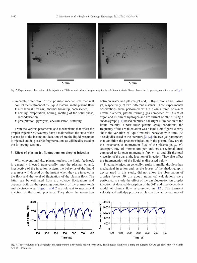
Fig. 2. Experimental observation of the injection of 300-µm water drops in a plasma jet at two different instants. Same plasma torch operating conditions as in Fig. 1.
4460 C. Marchand et al. / Surface & Coatings Technology 202 (2008) 4458–4464
- Accurate description of the possible mechanisms that willcontrol the treatment of the liquid material in the plasma flow• mechanical break-up, thermal break-up, coalescence,• heating, evaporation, boiling, melting of the solid phase,recondensation,
• precipitation, pyrolysis, crystallisation, sintering.
From the various parameters and mechanisms that affect thedroplet trajectories, two may have a major effect, the state of theplasma jet at the instant and location where the liquid precursoris injected and its possible fragmentation, as will be discussed inthe following sections.
3. Effect of plasma jet fluctuations on droplet injection
With conventional d.c. plasma torches, the liquid feedstockis generally injected transversally into the plasma jet and,irrespective of the injection system, the behavior of the liquidprecursor will depend on the instant when they are injected inthe flow and the level of fluctuation of the plasma flow. Thelatter can be estimated from arc voltage fluctuations anddepends both on the operating conditions of the plasma torchand electrode wear. Figs. 1 and 2 are relevant to mechanicalinjection of the liquid precursor. They show the interaction
Fig. 3. Time-evolution of gas velocity and temperature at the torch exit on torch axAr+15 Nl/min H2.
between water and plasma jet and, 300-µm blobs and plasmajet, respectively, at two different instants. These experimentalobservations were performed with a plasma torch of 6-mmnozzle diameter, plasma-forming gas composed of 33 slm ofargon and 10 slm of hydrogen and arc current of 500 A using ashadowgraph [11] based on pulsed backlight illumination of theliquid material. Under these plasma spray conditions, thefrequency of the arc fluctuation was 6 kHz. Both figures clearlyshow the variation of liquid material behavior with time. Asalready discussed in the literature [2,12], the two gas parametersthat condition the precursor injection in the plasma flow are (i)the instantaneous momentum flux of the plasma jet ρg ·v
2g
(transport rate of momentum per unit cross-sectional area)compared to its own momentum flux ρl .·vl
2 and (ii) the totalviscosity of the gas at the location of injection. They also affectthe fragmentation of the liquid as discussed below.
Pneumatic injection generally results in smaller droplets thanmechanical injection and, as the lenses of the shadowgraphydevice used in this study, did not allow the observation ofdroplets below 50 µm about, numerical calculations wereperformed to study the effect of the gas fluctuation on dropletinjection. A detailed description of the 3-D and time-dependentmodel of plasma flow is presented in [12]. The transientvelocity and enthalpy profiles of plasma flow at the entrance of
is. Torch nozzle diameter: 6 mm; arc current: 600 A; gas flow rate: 45 Nl/min
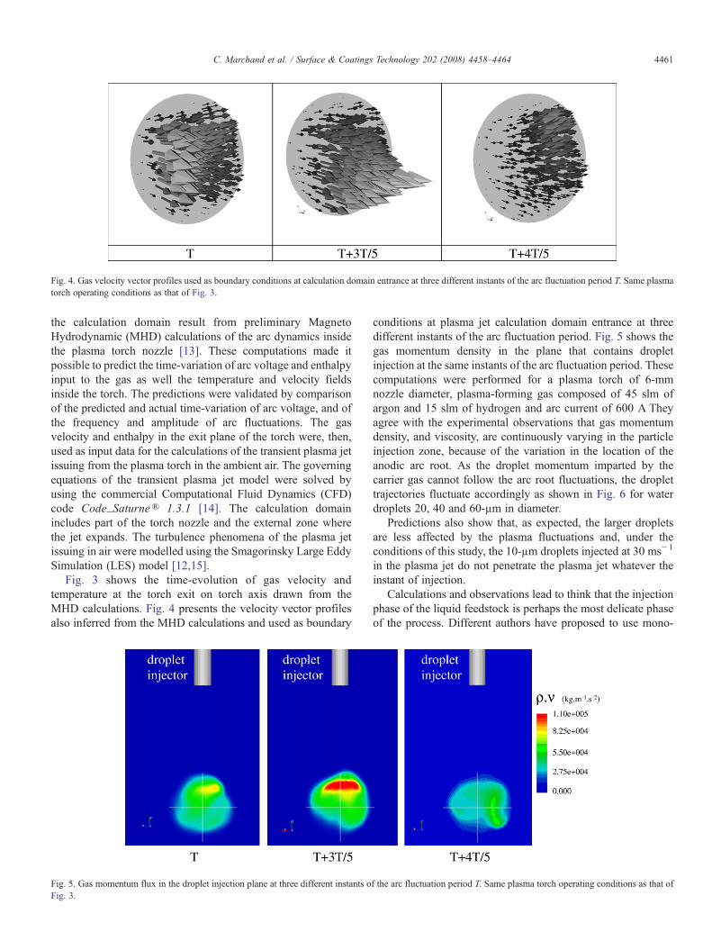
Fig. 4. Gas velocity vector profiles used as boundary conditions at calculation domain entrance at three different instants of the arc fluctuation period T. Same plasmatorch operating conditions as that of Fig. 3.
4461C. Marchand et al. / Surface & Coatings Technology 202 (2008) 4458–4464
the calculation domain result from preliminary MagnetoHydrodynamic (MHD) calculations of the arc dynamics insidethe plasma torch nozzle [13]. These computations made itpossible to predict the time-variation of arc voltage and enthalpyinput to the gas as well the temperature and velocity fieldsinside the torch. The predictions were validated by comparisonof the predicted and actual time-variation of arc voltage, and ofthe frequency and amplitude of arc fluctuations. The gasvelocity and enthalpy in the exit plane of the torch were, then,used as input data for the calculations of the transient plasma jetissuing from the plasma torch in the ambient air. The governingequations of the transient plasma jet model were solved byusing the commercial Computational Fluid Dynamics (CFD)code Code_Saturne® 1.3.1 [14]. The calculation domainincludes part of the torch nozzle and the external zone wherethe jet expands. The turbulence phenomena of the plasma jetissuing in air were modelled using the Smagorinsky Large EddySimulation (LES) model [12,15].
Fig. 3 shows the time-evolution of gas velocity andtemperature at the torch exit on torch axis drawn from theMHD calculations. Fig. 4 presents the velocity vector profilesalso inferred from the MHD calculations and used as boundary
Fig. 5. Gas momentum flux in the droplet injection plane at three different instants oFig. 3.
conditions at plasma jet calculation domain entrance at threedifferent instants of the arc fluctuation period. Fig. 5 shows thegas momentum density in the plane that contains dropletinjection at the same instants of the arc fluctuation period. Thesecomputations were performed for a plasma torch of 6-mmnozzle diameter, plasma-forming gas composed of 45 slm ofargon and 15 slm of hydrogen and arc current of 600 A Theyagree with the experimental observations that gas momentumdensity, and viscosity, are continuously varying in the particleinjection zone, because of the variation in the location of theanodic arc root. As the droplet momentum imparted by thecarrier gas cannot follow the arc root fluctuations, the droplettrajectories fluctuate accordingly as shown in Fig. 6 for waterdroplets 20, 40 and 60-µm in diameter.
Predictions also show that, as expected, the larger dropletsare less affected by the plasma fluctuations and, under theconditions of this study, the 10-µm droplets injected at 30 ms− 1
in the plasma jet do not penetrate the plasma jet whatever theinstant of injection.
Calculations and observations lead to think that the injectionphase of the liquid feedstock is perhaps the most delicate phaseof the process. Different authors have proposed to use mono-
f the arc fluctuation period T. Same plasma torch operating conditions as that of
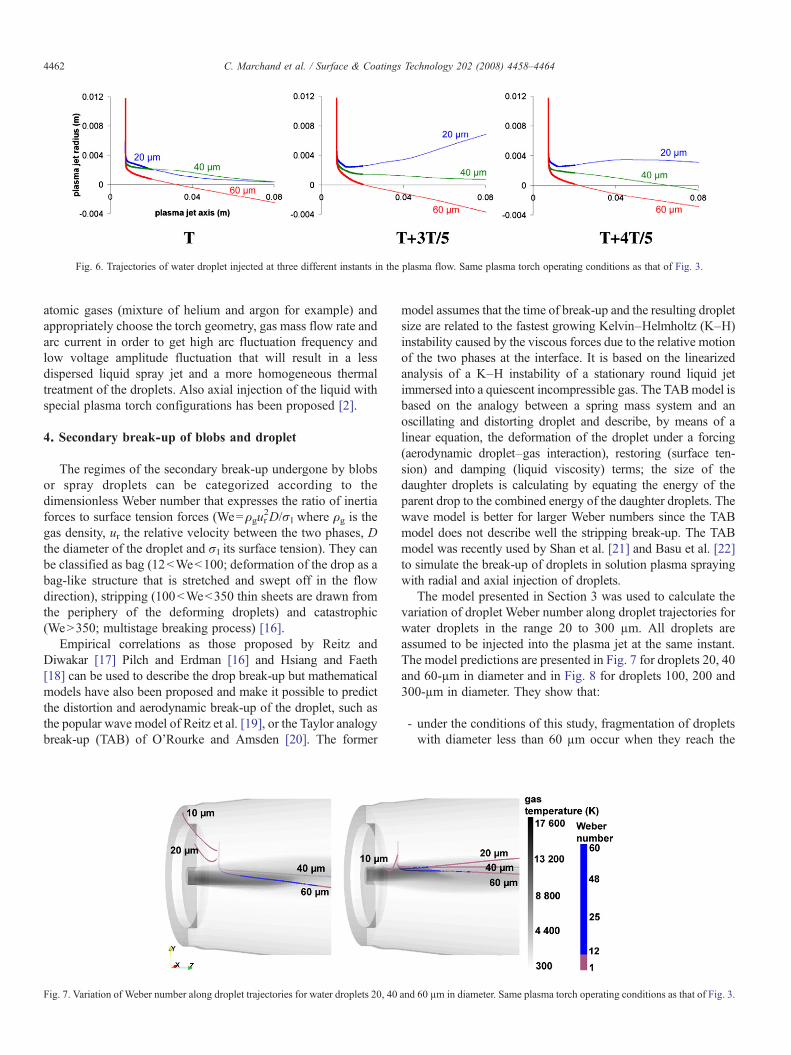
Fig. 6. Trajectories of water droplet injected at three different instants in the plasma flow. Same plasma torch operating conditions as that of Fig. 3.
4462 C. Marchand et al. / Surface & Coatings Technology 202 (2008) 4458–4464
atomic gases (mixture of helium and argon for example) andappropriately choose the torch geometry, gas mass flow rate andarc current in order to get high arc fluctuation frequency andlow voltage amplitude fluctuation that will result in a lessdispersed liquid spray jet and a more homogeneous thermaltreatment of the droplets. Also axial injection of the liquid withspecial plasma torch configurations has been proposed [2].
4. Secondary break-up of blobs and droplet
The regimes of the secondary break-up undergone by blobsor spray droplets can be categorized according to thedimensionless Weber number that expresses the ratio of inertiaforces to surface tension forces (We=ρgur
2D/σl where ρg is thegas density, ur the relative velocity between the two phases, Dthe diameter of the droplet and σl its surface tension). They canbe classified as bag (12bWeb100; deformation of the drop as abag-like structure that is stretched and swept off in the flowdirection), stripping (100bWeb350 thin sheets are drawn fromthe periphery of the deforming droplets) and catastrophic(WeN350; multistage breaking process) [16].
Empirical correlations as those proposed by Reitz andDiwakar [17] Pilch and Erdman [16] and Hsiang and Faeth[18] can be used to describe the drop break-up but mathematicalmodels have also been proposed and make it possible to predictthe distortion and aerodynamic break-up of the droplet, such asthe popular wave model of Reitz et al. [19], or the Taylor analogybreak-up (TAB) of O'Rourke and Amsden [20]. The former
Fig. 7. Variation of Weber number along droplet trajectories for water droplets 20, 40
model assumes that the time of break-up and the resulting dropletsize are related to the fastest growing Kelvin–Helmholtz (K–H)instability caused by the viscous forces due to the relative motionof the two phases at the interface. It is based on the linearizedanalysis of a K–H instability of a stationary round liquid jetimmersed into a quiescent incompressible gas. The TABmodel isbased on the analogy between a spring mass system and anoscillating and distorting droplet and describe, by means of alinear equation, the deformation of the droplet under a forcing(aerodynamic droplet–gas interaction), restoring (surface ten-sion) and damping (liquid viscosity) terms; the size of thedaughter droplets is calculating by equating the energy of theparent drop to the combined energy of the daughter droplets. Thewave model is better for larger Weber numbers since the TABmodel does not describe well the stripping break-up. The TABmodel was recently used by Shan et al. [21] and Basu et al. [22]to simulate the break-up of droplets in solution plasma sprayingwith radial and axial injection of droplets.
The model presented in Section 3 was used to calculate thevariation of droplet Weber number along droplet trajectories forwater droplets in the range 20 to 300 µm. All droplets areassumed to be injected into the plasma jet at the same instant.The model predictions are presented in Fig. 7 for droplets 20, 40and 60-µm in diameter and in Fig. 8 for droplets 100, 200 and300-µm in diameter. They show that:
- under the conditions of this study, fragmentation of dropletswith diameter less than 60 µm occur when they reach the
and 60 µm in diameter. Same plasma torch operating conditions as that of Fig. 3.
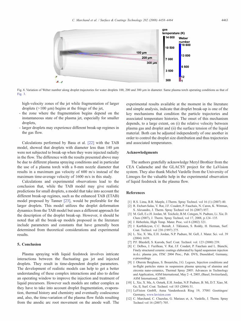
Fig. 8. Variation of Weber number along droplet trajectories for water droplets 100, 200 and 300 µm in diameter. Same plasma torch operating conditions as that ofFig. 3.
4463C. Marchand et al. / Surface & Coatings Technology 202 (2008) 4458–4464
high-velocity zones of the jet while fragmentation of largerdroplets (N100 µm) begins at the fringe of the jet,
- the zone where the fragmentation begins depend on theinstantaneous state of the plasma jet, especially for smallerdroplets,
- larger droplets may experience different break-up regimes inthe gas flow.
Calculations performed by Basu et al. [22] with the TABmodel, showed that droplets with diameter less than 140 µmwere not subjected to break-up when they were injected radiallyin the flow. The difference with the results presented above maybe due to different plasma spraying conditions and in particularthe use of a plasma torch with a 8-mm nozzle diameter thatresults in a maximum gas velocity of 600 m/s instead of themaximum time-average velocity of 1600 m/s in this study.
Calculations and experimental observations lead to theconclusion that, while the TAB model may give realisticpredictions for small droplets, a model that take into account thedifferent break-up regimes, such as the enhanced TAB (ETAB)model proposed by Tanner [23], would be preferable for thelarger droplets. This model utilizes the droplet deformationdynamics from the TAB model but uses a different approach forthe description of the droplet break-up. However, it should benoted that all the break-up models proposed in the literatureinclude parameters and constants that have generally beendetermined from theoretical considerations and experimentalresults.
5. Conclusion
Plasma spraying with liquid feedstock involves intricateinteractions between the fluctuating gas jet and injecteddroplets. They result in time-dependent droplet parameters.The development of realistic models can help to get a betterunderstanding of these complex interactions and also to definean operating window to improve the injection and treatment ofliquid precursors. However such models are rather complex asthey have to take into account droplet fragmentation, evapora-tion, thermal history and chemistry and eventually coalescenceand, also, the time-variation of the plasma flow fields resultingfrom the anodic arc root movement on the anode wall. The
experimental results available at the moment in the literatureand simple analysis, indicate that droplet break-up is one of thekey mechanisms that condition the particle trajectories andassociated temperature histories. The onset of this mechanismdepends, to a large extent, on (i) the relative velocity betweenplasma gas and droplet and (ii) the surface tension of the liquidmaterial. Both can be adjusted independently of one another inorder to control the droplet size distribution and thus trajectoriesand associated temperatures.
Acknowledgments
The authors gratefully acknowledge Meryl Brothier from theCEA Cadarache and the GLACSY project for the LaVisionsystem. They also thank Michel Vardelle from the University ofLimoges for the valuable help in the experimental observationof liquid feedstock in the plasma flow.
References
[1] R.S. Lima, B.R. Marple, J.Therm. Spray Technol. vol 16 (1) (2007) 40.[2] R. Etchart-Salas, V. Rat, J.F. Coudert, P. Fauchais, N. Caron, K. Wittman,
S. Alexandre, J. Therm. Spray Technol vol 16 (2007) 857.[3] M. Gell, E.c.H. Jordan, M. Teicholz, B.M. Cetegen, N. Padture, Li. Xie, D.
Chen (2007), J. Therm. Spray Technol, vol 17, 2008, p.124–135.[4] J. Heberlein, High Temp. Mater. Proc. vol 6 (2002) 321.[5] J. Karthikeyan, C.C. Berndt, J. Tikkanen, S. Reddy, H. Herman, Surf.
Coat. Technol. vol 238 (1997) 275.[6] L. Xie, X. Ma, E.H. Jordan, N.P. Padture, M. Gell, J. Mater. Sci. vol. 39
(2004) 1639.[7] P.F. Blazdell, S. Kuroda, Surf. Coat. Technol. vol. 123 (2000) 239.[8] C. Delbos, J. Fazilleau, V. Rat, J.F. Coudert, P. Fauchais and L. Bianchi,
Finely structured ceramic coatings elaborated by liquid suspension injectionin d.c. plasma jets, ITSC 2004 Proc., Pub. DVS, Dusseldorf, Germany,e-proceedings.
[9] J. Oberste Berghaus, S. Bouaricha, J.G. Legoux, Injection conditions andin-flight particles states in suspension plasma spraying of alumina andzirconia nano-ceramics, Thermal Spray 2005: Advances in Technologyand Application, ASM International, May 2–4, 2005, (Basel, Switzerland),ASM International, 2005.
[10] L. Xie, X. Ma, A. Ozturk, E.H. Jordan, N.P. Padture, B. Mi, D.T. Xiao, M.Ge, ll, Surf. Coat. Technol. vol 183 (2004) 51.
[11] LaVision GmbH, Anna Vandenhoeck Ring 19, 37081 Goettingen/Germany, www.lavision.com
[12] C. Marchand, C. Chazelas, G. Mariaux et, A. Vardelle, J. Therm. SprayTechnol vol 16 (2007) 705.

4464 C. Marchand et al. / Surface & Coatings Technology 202 (2008) 4458–4464
[13] C. Baudry, A. Vardelle, G. Mariaux, J. High Temp. Mat. Processes vol 9(2005) 1.
[14] F. Archambeau, N. Méchitoua, M. Sakiz, Code_Saturne: a finite volumecode for the computation of turbulent incompressible flows—industrialapplications, International Journal on Finite Volumes, Vol. 1, 2004, p. 1.
[15] P. Sagaut, Introduction to large eddy scale simulations for the modeling ofuncompresible flows, in French, Mathématiques et Applications, Vol. 30,Springer-Verlag.
[16] M. Pilch, C. Erdmann, Int. J. Multiphase Flow vol 13 (1987) 741.
[17] R.D. Reitz, R. Diwakar, SAE Technical paper series, 1986 No. 860469.[18] L.-P. Hsiang, G.M. Faeth, J. Multiphase Flow Vol. 18 (1992) 635.[19] R.D. Reitz, At. Spray Technol. vol 3 (1987) 309.[20] P.J. O'Rourke, A.A. Amsden, SAE Technical Paper 872089, 1987.[21] Y. Shan, T.W. Coyle, J. Mostaghimi, J. Therm. Spray Technol vol 16 (2007)
698.[22] S. Basu, E. Jordan, B. Cetegen, J. Therm. Spray Technol. vol 1 (2007) 60.[23] F.X. Tanner, SAE Technical Paper 970050, 1997.