Embed Size (px)
Citation preview

ERMSAR 2015, Marseille March 24 – 26, 2015
Modelling of Hydrogen Generation during Spent Fuel
Pool LOCA using Thermal Hydraulic and Severe
Accident Code SOCRAT/V5
A.Vasiliev
Nuclear Safety Institute of Russian Academy of Sciences (IBRAE),
B.Tulskaya 52, 115191 Moscow, Russia

ERMSAR 2015, Marseille March 24 – 26, 2015
1. Purpose
2. Hints to Model SFP LOCA
3. Main Results of Modelling by SOCRAT Code
4. Modelling of Zr Oxidation in H2O-O2-N2 Gas
Mixtures in Application to SFP LOCA
5. Conclusions
Content
of Presentation

ERMSAR 2015, Marseille March 24 – 26, 2015
Importance
In the course of postulated spent fuel pool loss of coolant accident (SFP
LOCA) at NPP, a huge amount of hydrogen can be generated due to
chemical reactions of zirconium and steel with steam-oxygen-nitrogen
atmosphere.
Highly explosive mixture of hydrogen and oxygen may threaten to
containment integrity.
Loss of SFP water may result in fuel assemblies heat-up, oxidation,
melting and relocation accompanied by radioactive nuclides release.
This is why SFP LOCA modelling in SA codes is necessary.

ERMSAR 2015, Marseille March 24 – 26, 2015
Difficulties in Modelling SFP LOCA Realistically
Thermo-hydraulic, thermo-mechanical, chemical and severe accident processes
under SFP LOCA conditions are extremely complicated and very far from
complete understanding.
It is not clear how to model specific phenomena in codes keeping in mind that the
phenomena are modelled in codes with many assumptions and limitations.
Scientific community has not come to consensus yet how far to severe accident
range would SFP LOCA develop.
ERMSAR 2015, Marseille March 24 – 26, 2015
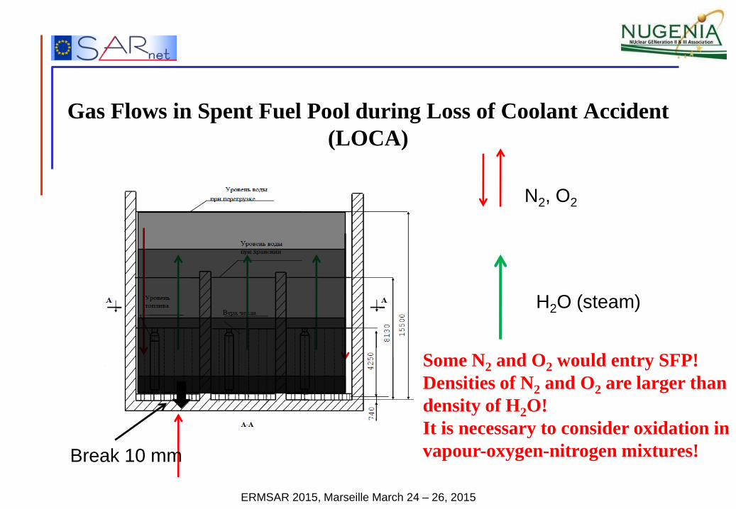
Gas Flows in Spent Fuel Pool during Loss of Coolant Accident
(LOCA)
Break 10 mm
N2, O2
H2O (steam)
Some N2 and O2 would entry SFP!
Densities of N2 and O2 are larger than
density of H2O!
It is necessary to consider oxidation in
vapour-oxygen-nitrogen mixtures!

ERMSAR 2015, Marseille March 24 – 26, 2015
B. Jaeckel, J. Birchley, L. Fernandez-Moguel. Spent Fuel Pool
under Severe Accident Conditions. Proc. 22nd Int. Conf. on Nuclear
Engineering (ICONE22), July 7-11, 2014, Prague, Czech Republic.
ICONE22-30729.
M. Steinbrück, F. Oliveira da Silva, H.J. Seifert. High-Temperature
Oxidation of Zircaloy-4 in Steam-Nitrogen Mixtures. NuMat2014:
The Nuclear Materials Conference, Clearwater Beach, Florida,
USA, October27-30, 2014.
Zr oxidation in H2O-O2-N2
mixture is very far from
classical parabolic law!
SFP LOCA Investigation
stakeholders
EDF, France
PSI, Switzerland
IRSN, France
IBRAE, Russia
NRCKI, Russia

ERMSAR 2015, Marseille March 24 – 26, 2015
Hints to Model SFP LOCA in Realistic Way
1. To estimate the thermal behaviour adequately it is necessary to divide SFP into two or several channels.
2. When evaluating radiative heat transfer from SFP structures to external boundaries in upward, sideward and downward directions we should take into account the temperature profiles in system. The temperature at periphery is less than the temperature in the centre.
3. After pool dry-out, the convective gas velocity established in FAs is about 10-20 cm/s due to hydraulic resistances, so the convective cooling is limited.
4. It is necessary to adequately take into account the high chemical power of Zr oxidation in steam-oxygen-nitrogen mixtures.
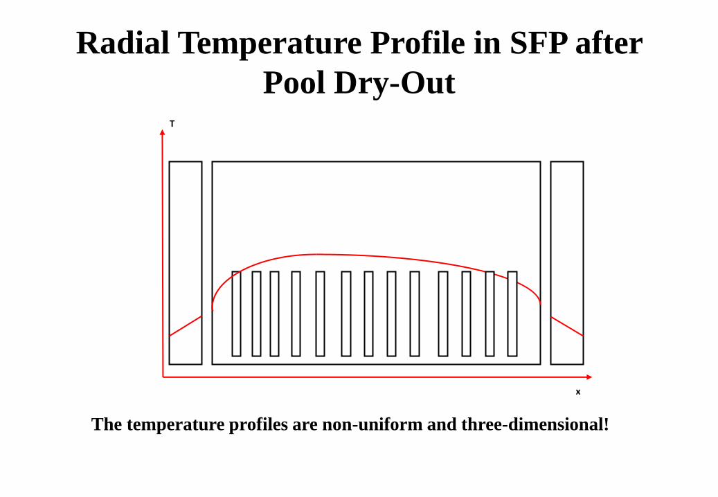
Radial Temperature Profile in SFP after
Pool Dry-Out T
x
The temperature profiles are non-uniform and three-dimensional!

Representative Scenario of Hypothetical
SFP LOCA at Balakovo NPP Unit 1 with
VVER-1000 Nuclear Reactor Storage time, years Pool “a” Pool “b” Pool “c”
3 days
30 days
0.8
2.2
3.6
4.7
5.8
10.2
65 10
16
60
30
2
1
1
60 4
13
0
30
4
0
0
38 3
23
5
0
0
0
0
Power, MW 6.78 5.91 3.82
Total power, MW 16.51
Pool “a” Pool “b” Pool “c”
No break
Olny loss of water supply
(blackout)
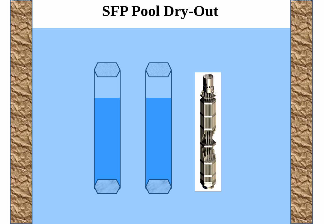
SFP Pool Dry-Out

Geometry of
Radiative Heat
Exchange in SFP
R
H
d
D qrad,s
qrad,u
Water
red colour – high
heat load
green colour – low
heat load

Propagation of Burning Wave
32
)2/(
3T
D
dBrad
d
D
rad
Rt
2
R
3 30 0.8 2.2 3.6 4.7 5.8 10.2 FA storage times
t 50,000 s
T1500K

Linear Kinetics Results in Drastic Augmentation
of Oxidation rate and Heat Generation!
0 4000 8000 12000
Время, с
0
2
4
6
8
10
Мощность
реакции
окислен
ия
, Вт
/твэл
T = 1273Kair parabolic
steam parabolic
steam+nitrogen linear
Total power generation of one FA can be increased by 1 kW even at temperature 1000С !
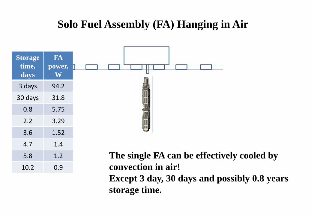
Solo Fuel Assembly (FA) Hanging in Air
The single FA can be effectively cooled by
convection in air!
Except 3 day, 30 days and possibly 0.8 years
storage time.
Storage
time,
days
FA
power,
W
3 days 94.2
30 days 31.8
0.8 5.75
2.2 3.29
3.6 1.52
4.7 1.4
5.8 1.2
10.2 0.9

Ensemble of FAs in SFP
The behaviour of FAs Ensemble is completely different
compared to single assembly!
3 30 0.8 2.2 3.6 4.7 5.8 10.2

SFP Nodalization Scheme for SOCRAT
water inlet
1
2
3
4
17
18
Water volume
coolant outlet at pressure p(t)
SF Pool
rigid wall
Boundary condition
switch
Dome
Concrete
Air volume
FA_4.5y FA_7.5y FA_6.0y FA_9.0y FA_3.0d FA_1.5y
water flow outlet
BASKETS
rigid wall
CH
1
CH
4
CH
44
CH
0
FA_3.0y
Boundary condition switch
CH
2
BBASKETS
3d - 3y
CH
11
CH
111
CH
3
CH
33 CH
5
CH
7 CH
55
CH
6
CH
66
CH
77
CH
8 CH
88
Concrete
CH
a CH
b

Water Mass Level
Pool “a” Pool “b” Pool “c”

Hydrogen Production

Temperature, Nuclear and Chemical Power
Pool a
Chemical heat generation is very high!
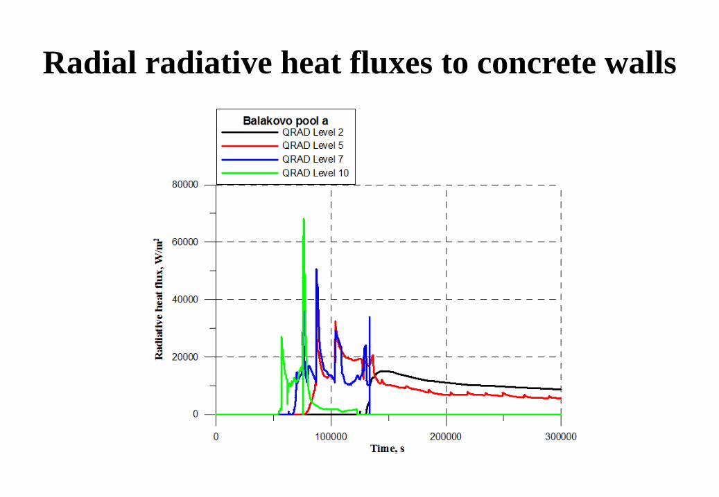
Radial radiative heat fluxes to concrete walls

Masses of Materials in SFP
0 100000 200000 300000 400000
Time, s
0
40000
80000
120000
Mass
, k
g
Materials in pool aUO2
Zr
ZrO2
ss
FeO NiO Cr2O3

H2 Production: Total and due SS Oxidation
0 100000 200000 300000 400000
Time, s
0
400
800
1200
1600H
yd
rogen
pro
du
ctio
n, k
g
pool atotal H2
H2 due to ss oxidation
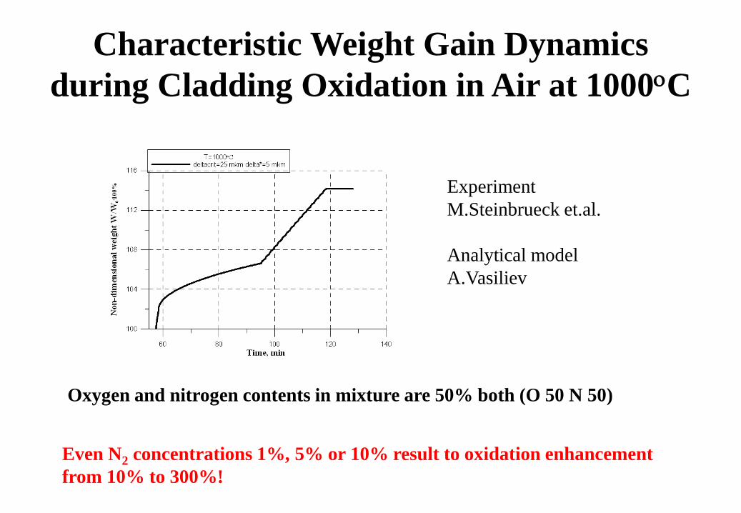
Characteristic Weight Gain Dynamics
during Cladding Oxidation in Air at 1000C
Oxygen and nitrogen contents in mixture are 50% both (O 50 N 50)
Experiment
M.Steinbrueck et.al.
Analytical model
A.Vasiliev
Even N2 concentrations 1%, 5% or 10% result to oxidation enhancement
from 10% to 300%!
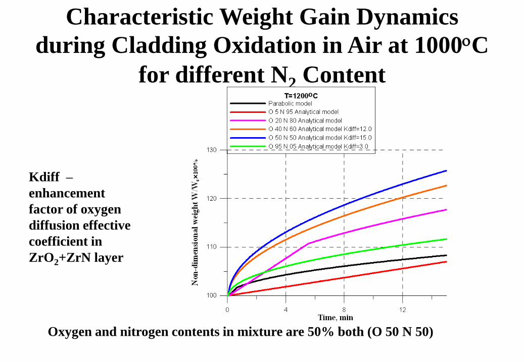
Characteristic Weight Gain Dynamics
during Cladding Oxidation in Air at 1000C for different N2 Content
Oxygen and nitrogen contents in mixture are 50% both (O 50 N 50)
Kdiff –
enhancement
factor of oxygen
diffusion effective
coefficient in
ZrO2+ZrN layer

H2 Generation for ilim=3 and ilim=4
iIim=3 – classical parabola
ilim=4 – enhanced oxygen diffusion coefficient in ZrO2 + ZrN layer
Kdiff is equal 3

Summary
The thermo-hydraulic and severe accident code SOCRAT/V5 was used for estimation of
hydrogen release during spent fuel pool accident with LOCA.
The representative scenario of hypothetical SFP LOCA at Balakovo NPP Unit 1 with
VVER-1000 nuclear reactor was considered.
The choice of cladding oxidation model strongly influences the hydrogen generation rate
– a key parameter for evaluation of hydrogen recombinating system effectiveness in NPP.
It was shown that the mass of hydrogen released during the SFP loss-of-coolant accident
can be about 3000 kg (even not taking into account the hydrogen released during molten
core-concrete interaction).
The maximum calculated hydrogen release rate was obtained in the case of enhanced
oxidation in steam-oxygen-nitrogen mixtures compared to the classical parabolic
oxidation in pure steam.