Embed Size (px)
Citation preview
Modelling, control and supervision strategies for aeronautical electrical networks
ing. Beniamino GUIDATutor: Prof. Alberto CAVALLO
Dipartimento di Ingegneria Industriale e dell’InformazioneSeconda Università degli studi di Napoli
“Best PhD Thesis in a Clean Sky project” Award
Summary
v Motivation and IntroductionvModeling, control and supervision of a bidirectional DC/DC convertervSupervision of an aeronautical electrical network for intelligent energy managementvConclusions and future extensions
Motivation
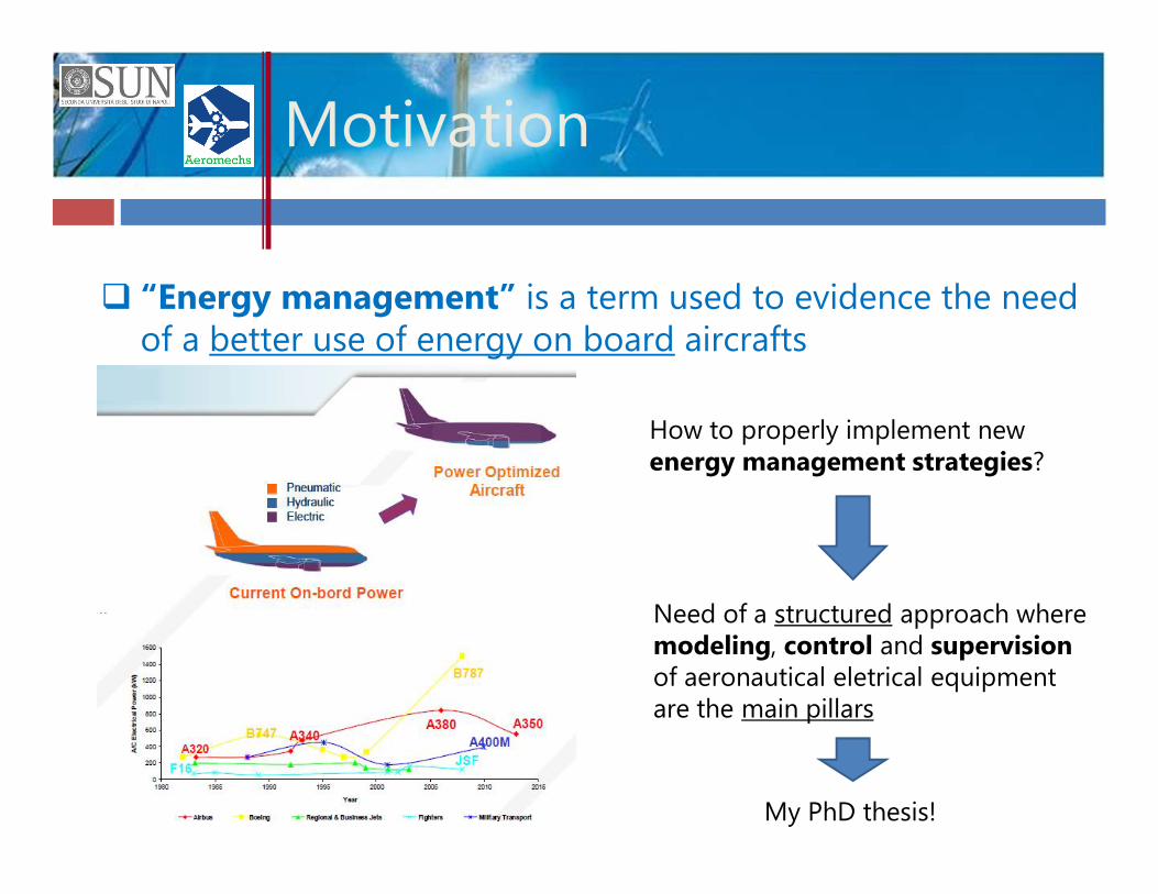
q “Energy management” is a term used to evidence the need of a better use of energy on board aircrafts
How to properly implement new energy management strategies?
Need of a structured approach wheremodeling, control and supervisionof aeronautical eletrical equipmentare the main pillars
My PhD thesis!
INTRODUCTION
A/c electrical systems
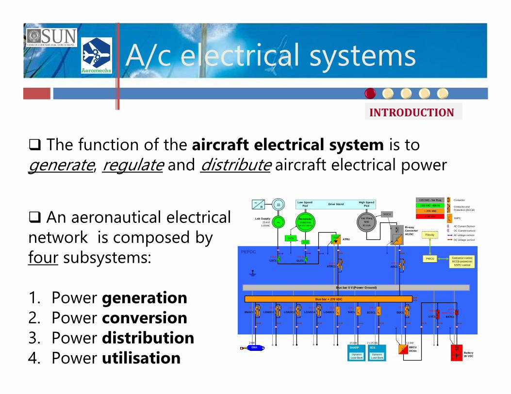
q The function of the aircraft electrical system is to generate, regulate and distribute aircraft electrical power
q An aeronautical electrical network is composed by four subsystems:
1. Power generation2. Power conversion3. Power distribution4. Power utilisation
PEPDC
Bus bar 0 V (Power Ground)
ATRU
115 VAC - 400 Hz
+ 28 VDC
+ 270 VDC
115 VAC - Var Freq
Contactor controlRCCB protection
SSPC control
Flexray
PMCU
Contactor and Protection (RCCB)
Contactor
AC Current Sensor
DC Current sensor
AC voltage sensor
DC voltage sensor
SSPC
2 kW
20 A
EMA
EMAC1
=~=
Lab Supply 25 kVA
115VAC
LSC1100 A
~
LOADC220 A
LOADC3100 A
200 A
LVC1
ECS
DynamicLoad Bank
2 x 25 kW
200 A
ECSC1
SHARP
DynamicLoad Bank
25 kW
100 A
SHC1LOADC120 A
LOADC4400 A
Bi-way ConverterAC/DC
400 AADC1
Var FreqS/G
85 kVA
SGCU
250 AATRC1
BBCUDC/dc
12 kW
50 A
DDC1
Bus bar + 270 VDC
Low Speed Pad Drive Stand High Speed
Pad
Battery 28 VDC
400 Apeak 750 A
BATC1
GLC1250 A
Generator50/60 kVA
115 VAC 400 Hz
GCUCTU
Modelling levels
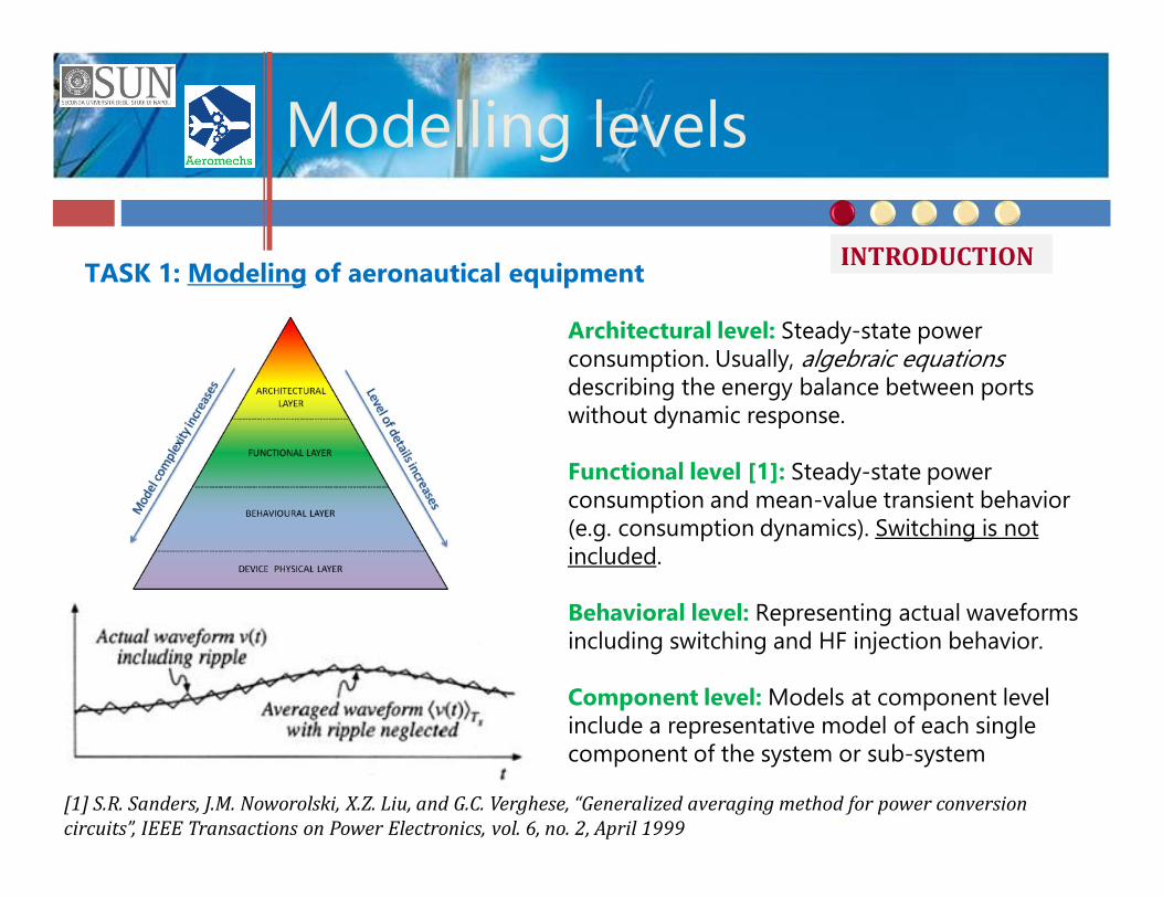
TASK 1: Modeling of aeronautical equipment
Architectural level: Steady-state power consumption. Usually, algebraic equations describing the energy balance between ports without dynamic response.
Functional level [1]: Steady-state power consumption and mean-value transient behavior (e.g. consumption dynamics). Switching is not included.
Behavioral level: Representing actual waveforms including switching and HF injection behavior.
Component level: Models at component level include a representative model of each single component of the system or sub-system
[1] S.R. Sanders, J.M. Noworolski, X.Z. Liu, and G.C. Verghese, “Generalized averaging method for power conversion circuits”, IEEE Transactions on Power Electronics, vol. 6, no. 2, April 1999
INTRODUCTION
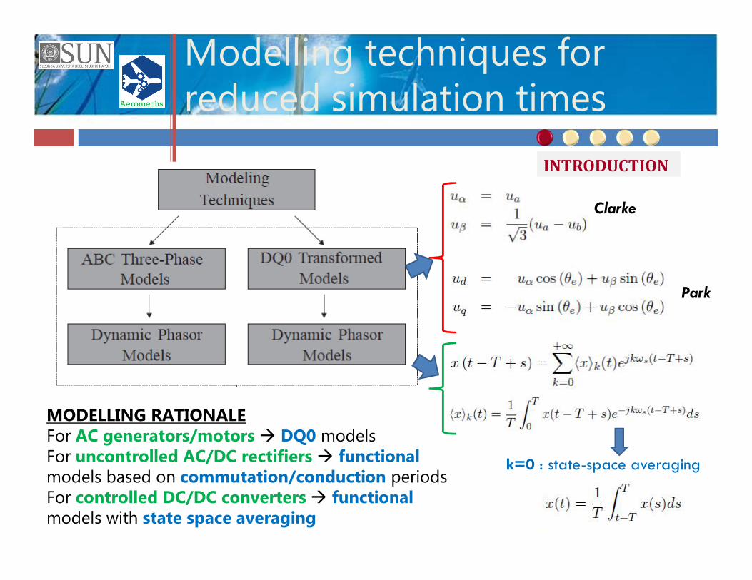
Modelling techniques for reduced simulation times
k=0 : state-space averaging
Clarke
Park
MODELLING RATIONALEFor AC generators/motors à DQ0 models For uncontrolled AC/DC rectifiers à functionalmodels based on commutation/conduction periodsFor controlled DC/DC converters à functionalmodels with state space averaging
INTRODUCTION
Control strategies
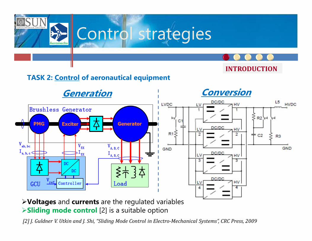
TASK 2: Control of aeronautical equipment
[2] J. Guldner V. Utkin and J. Shi, “Sliding Mode Control in Electro-Mechanical Systems”, CRC Press, 2009
Generation Conversion
ØVoltages and currents are the regulated variablesØSliding mode control [2] is a suitable option
INTRODUCTION
Modern control of aeronautical equipment
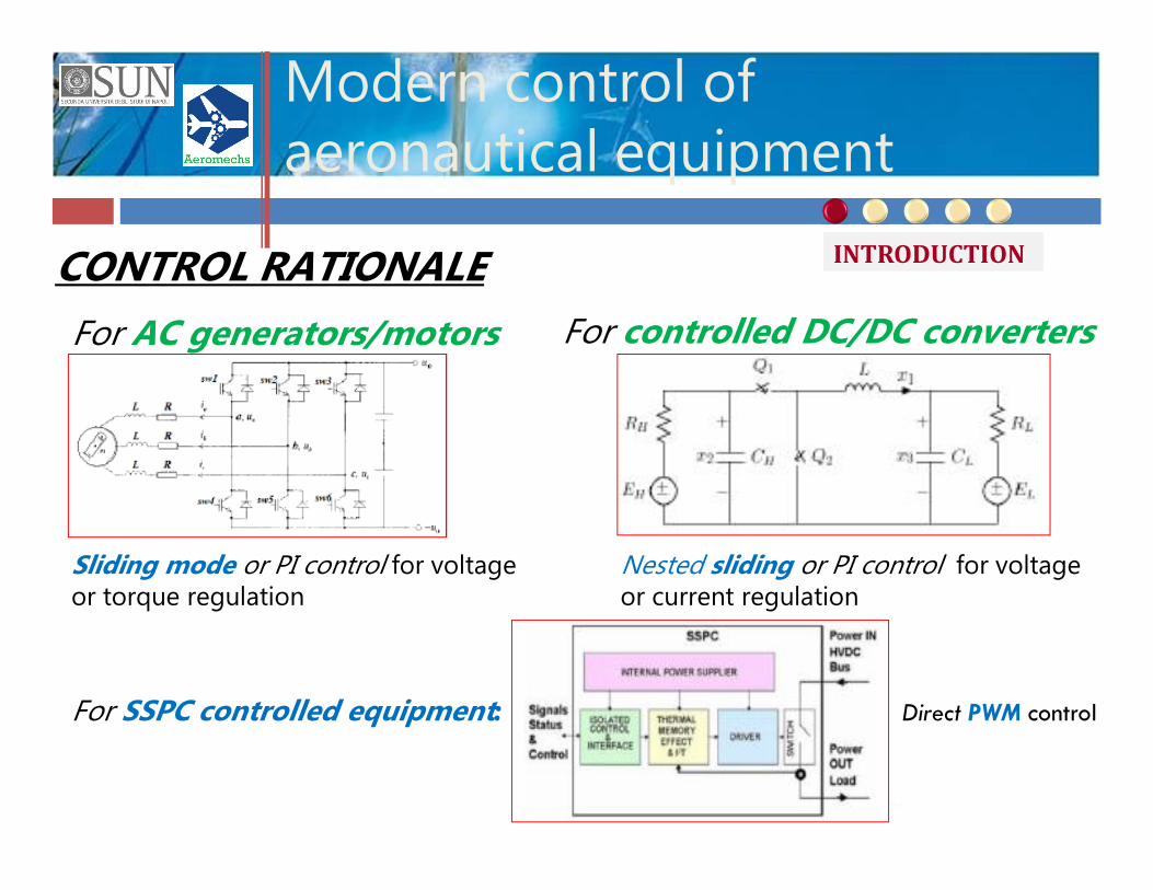
CONTROL RATIONALE
Nested sliding or PI control for voltage or current regulation
For SSPC controlled equipment:
Sliding mode or PI control for voltage or torque regulation
For AC generators/motors For controlled DC/DC converters
Direct PWM control
INTRODUCTION
Supervision strategies
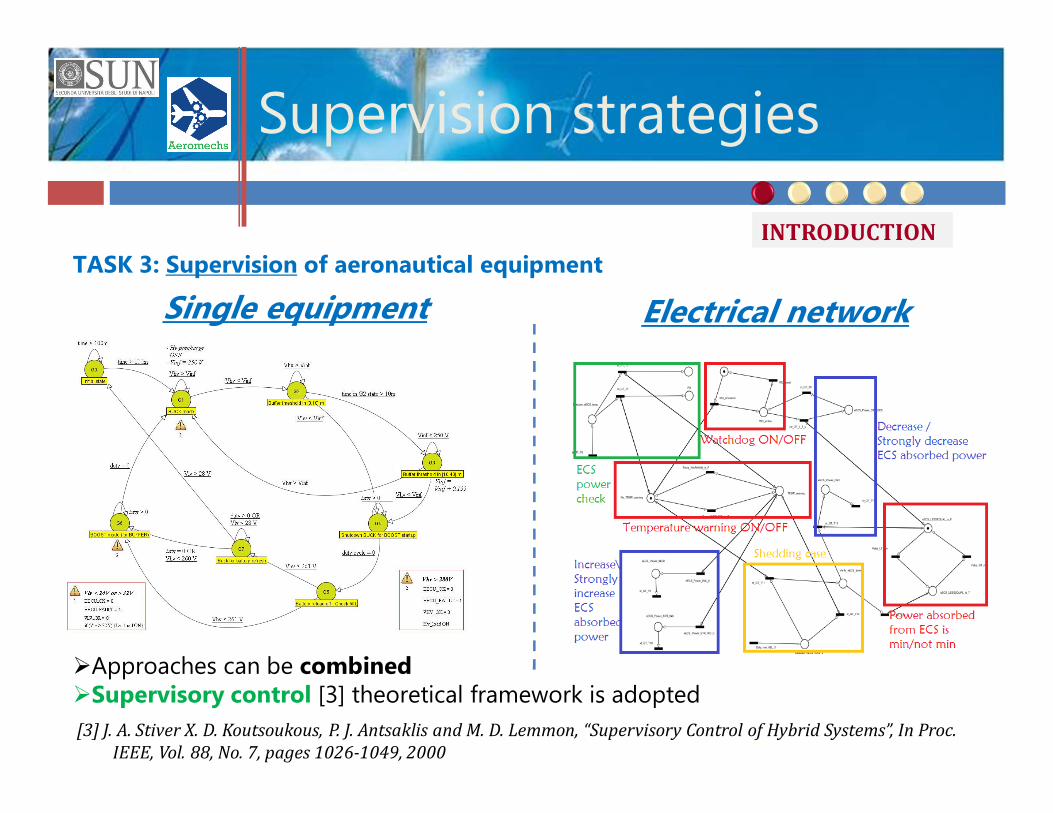
TASK 3: Supervision of aeronautical equipment
[3] J. A. Stiver X. D. Koutsoukous, P. J. Antsaklis and M. D. Lemmon, “Supervisory Control of Hybrid Systems”, In Proc. IEEE, Vol. 88, No. 7, pages 1026-1049, 2000
Single equipment Electrical network
ØApproaches can be combinedØSupervisory control [3] theoretical framework is adopted
INTRODUCTION
Supervision of equipment for energy management
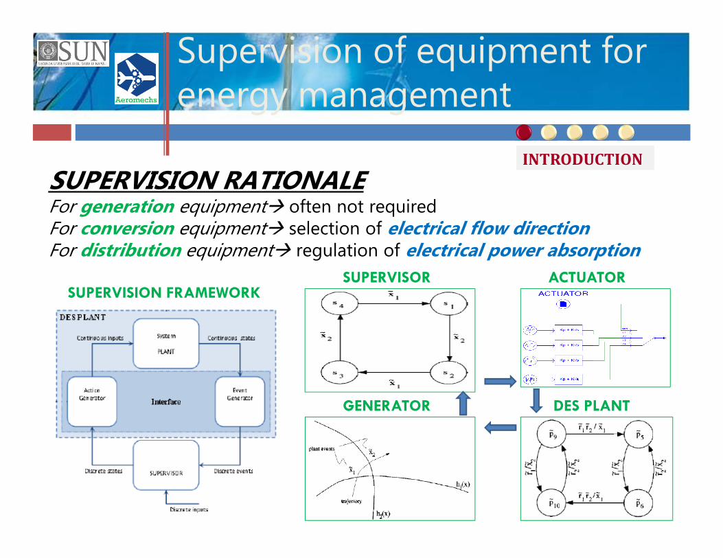
SUPERVISION RATIONALEFor generation equipmentà often not requiredFor conversion equipmentà selection of electrical flow directionFor distribution equipmentà regulation of electrical power absorption
GENERATOR DES PLANT
SUPERVISOR ACTUATORSUPERVISION FRAMEWORK
INTRODUCTION
DC/DC converter: modelling
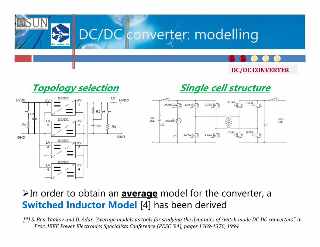
Topology selection Single cell structure
ØIn order to obtain an average model for the converter, aSwitched Inductor Model [4] has been derived[4] S. Ben-Yaakov and D. Adar, “Average models as tools for studying the dynamics of switch mode DC-DC converters”, in
Proc. IEEE Power Electronics Specialists Conference (PESC '94), pages 1369-1376, 1994
DC/DC CONVERTER
DC/DC converter: control
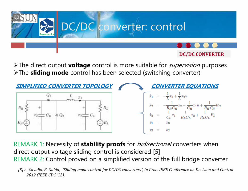
ØThe direct output voltage control is more suitable for supervision purposesØThe sliding mode control has been selected (switching converter)
SIMPLIFIED CONVERTER TOPOLOGY CONVERTER EQUATIONS
REMARK 1: Necessity of stability proofs for bidirectional converters when direct output voltage sliding control is considered [5]REMARK 2: Control proved on a simplified version of the full bridge converter
[5] A. Cavallo, B. Guida, “Sliding mode control for DC/DC converters”, In Proc. IEEE Conference on Decision and Control 2012 (IEEE CDC ‘12).
DC/DC CONVERTER
DC/DC converter: supervision
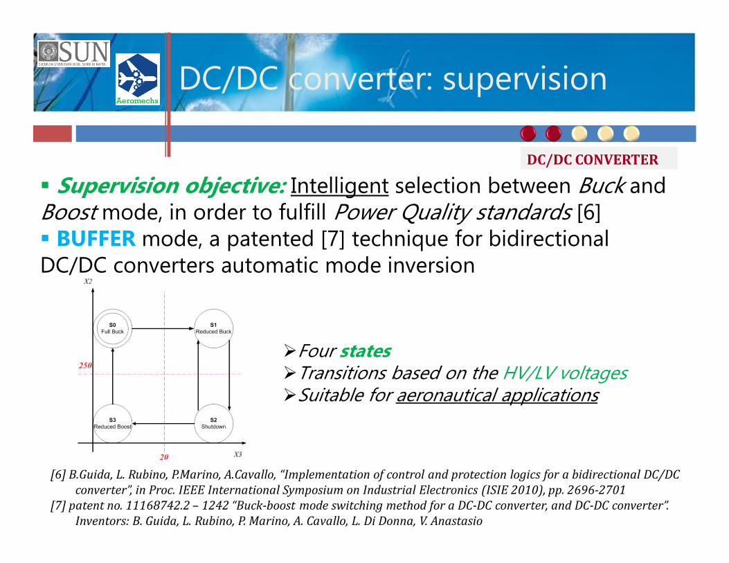
§ Supervision objective: Intelligent selection between Buck and Boost mode, in order to fulfill Power Quality standards [6]§ BUFFER mode, a patented [7] technique for bidirectional DC/DC converters automatic mode inversion
ØFour statesØTransitions based on the HV/LV voltagesØSuitable for aeronautical applications
[6] B.Guida, L. Rubino, P.Marino, A.Cavallo, “Implementation of control and protection logics for a bidirectional DC/DC converter”, in Proc. IEEE International Symposium on Industrial Electronics (ISIE 2010), pp. 2696-2701
[7] patent no. 11168742.2 – 1242 “Buck-boost mode switching method for a DC-DC converter, and DC-DC converter”. Inventors: B. Guida, L. Rubino, P. Marino, A. Cavallo, L. Di Donna, V. Anastasio
DC/DC CONVERTER
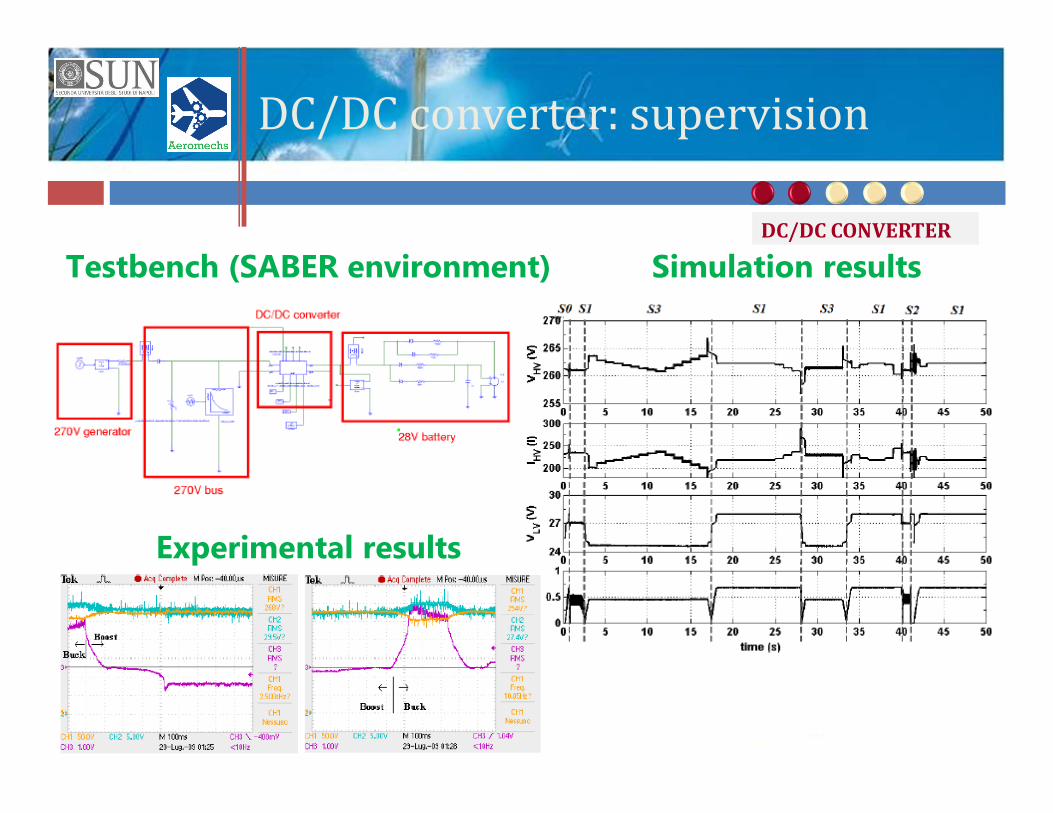
DC/DC converter: supervisionTestbench (SABER environment) Simulation results
Experimental results
DC/DC CONVERTER
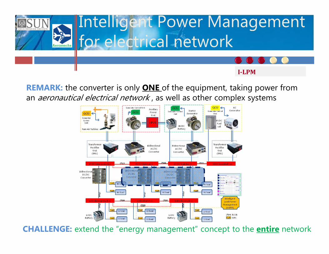
Intelligent Power Management for electrical network
REMARK: the converter is only ONE of the equipment, taking power from an aeronautical electrical network , as well as other complex systems
CHALLENGE: extend the “energy management” concept to the entire network
I-LPM
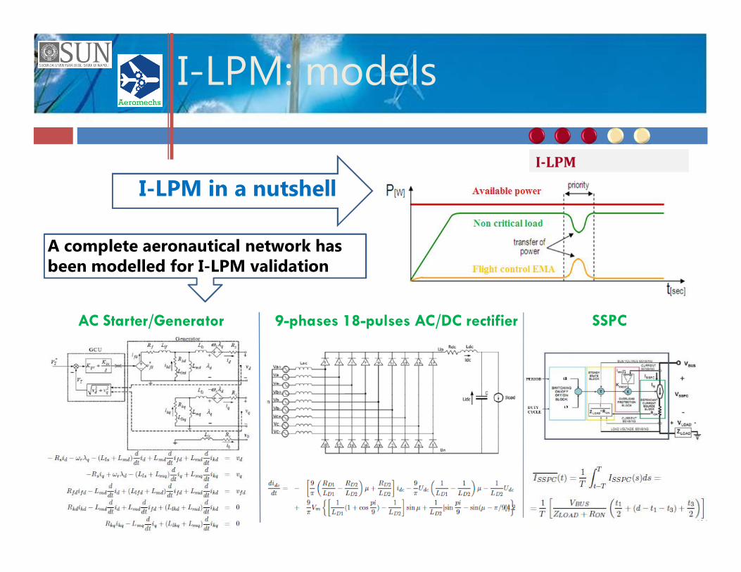
I-LPM: models
I-LPM in a nutshell
AC Starter/Generator 9-phases 18-pulses AC/DC rectifier SSPC
A complete aeronautical network hasbeen modelled for I-LPM validation
I-LPM
I-LPM: control
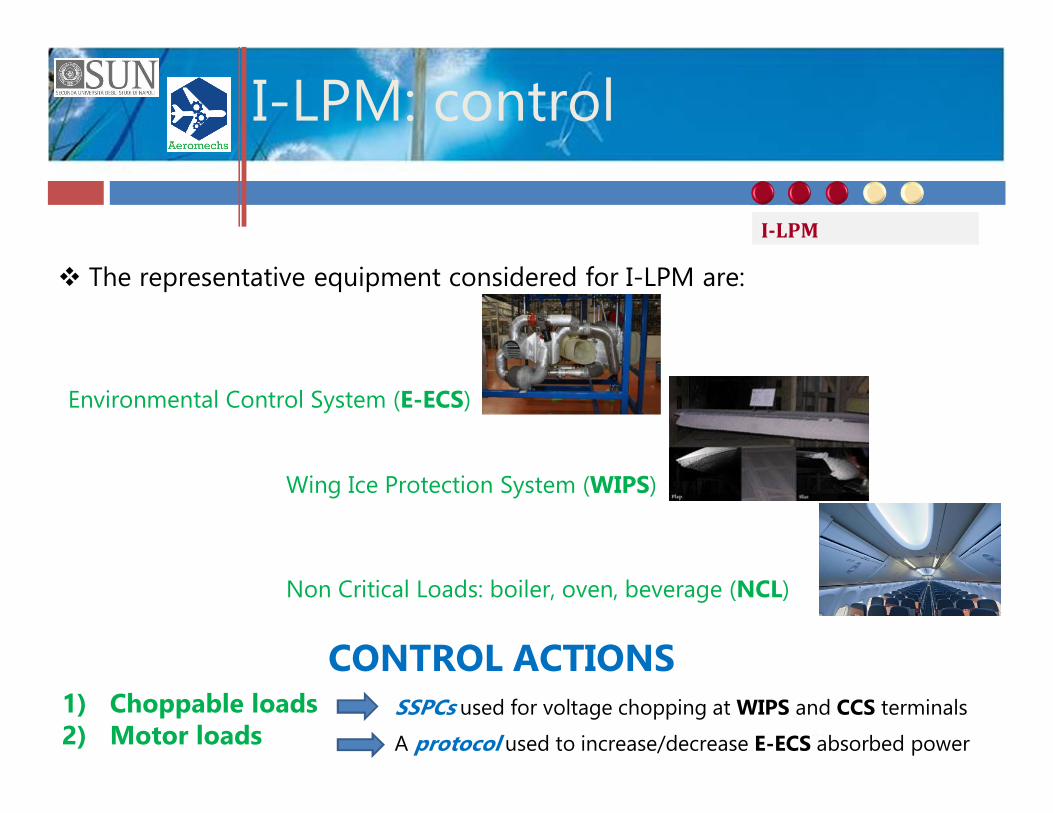
v The representative equipment considered for I-LPM are:
Non Critical Loads: boiler, oven, beverage (NCL)
Environmental Control System (E-ECS)
Wing Ice Protection System (WIPS)
1) Choppable loads2) Motor loads
SSPCs used for voltage chopping at WIPS and CCS terminals
A protocol used to increase/decrease E-ECS absorbed power
CONTROL ACTIONS
I-LPM
I-LPM: supervision
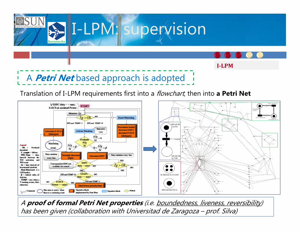
A Petri Net based approach is adopted
Translation of I-LPM requirements first into a flowchart, then into a Petri Net
A proof of formal Petri Net properties (i.e. boundedness, liveness, reversibility) has been given (collaboration with Universitad de Zaragoza – prof. Silva)
I-LPM
I-LPM results
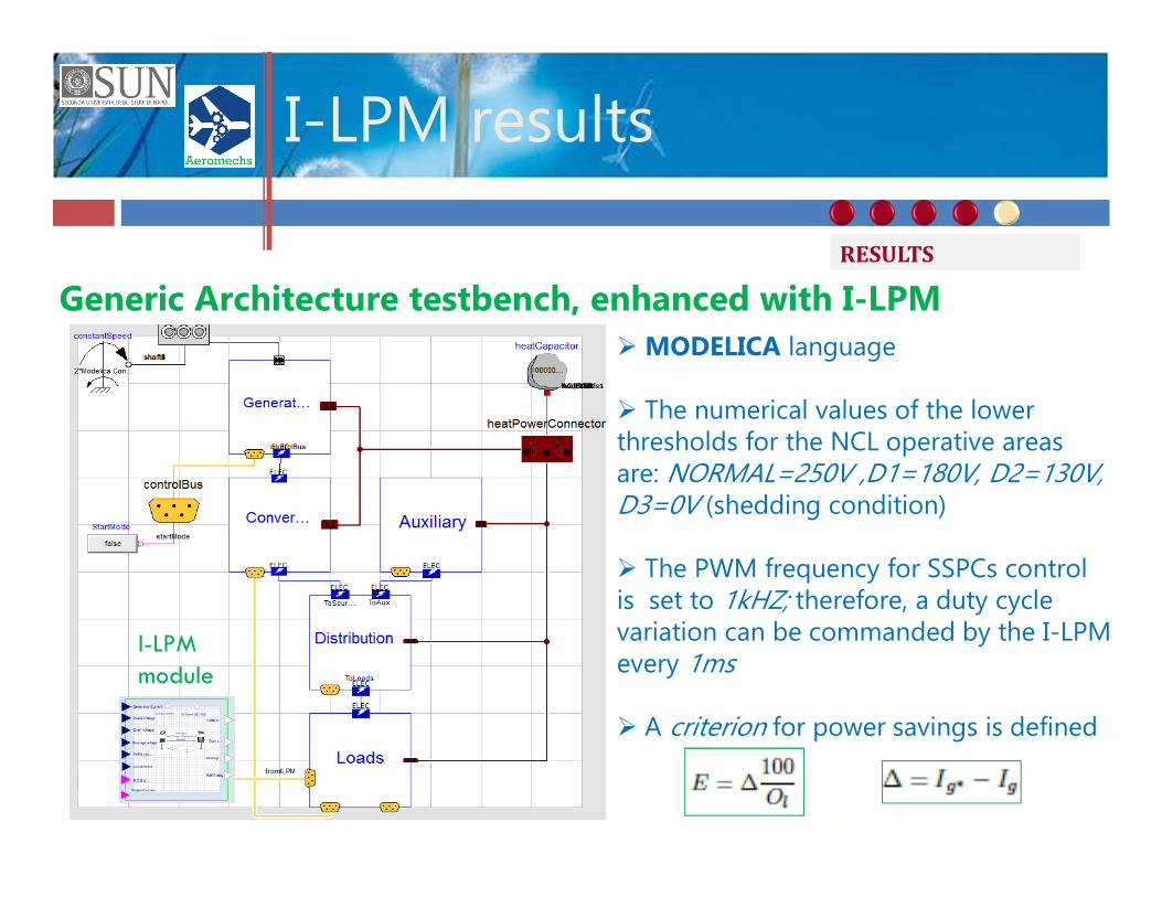
Generic Architecture testbench, enhanced with I-LPM
I-LPMmodule
ØMODELICA language
Ø The numerical values of the lower thresholds for the NCL operative areas are: NORMAL=250V ,D1=180V, D2=130V, D3=0V (shedding condition)
Ø The PWM frequency for SSPCs control is set to 1kHZ; therefore, a duty cycle variation can be commanded by the I-LPM every 1ms
Ø A criterion for power savings is defined
RESULTS
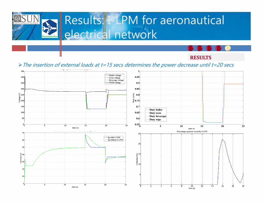
Results: I-LPM for aeronauticalelectrical network
ØThe insertion of external loads at t=15 secs determines the power decrease until t=20 secsRESULTS
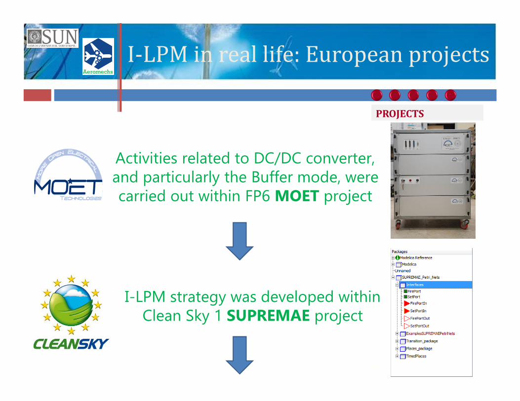
I-LPM in real life: European projectsActivities related to DC/DC converter, and particularly the Buffer mode, were carried out within FP6 MOET project
I-LPM strategy was developed within Clean Sky 1 SUPREMAE project
PROJECTS
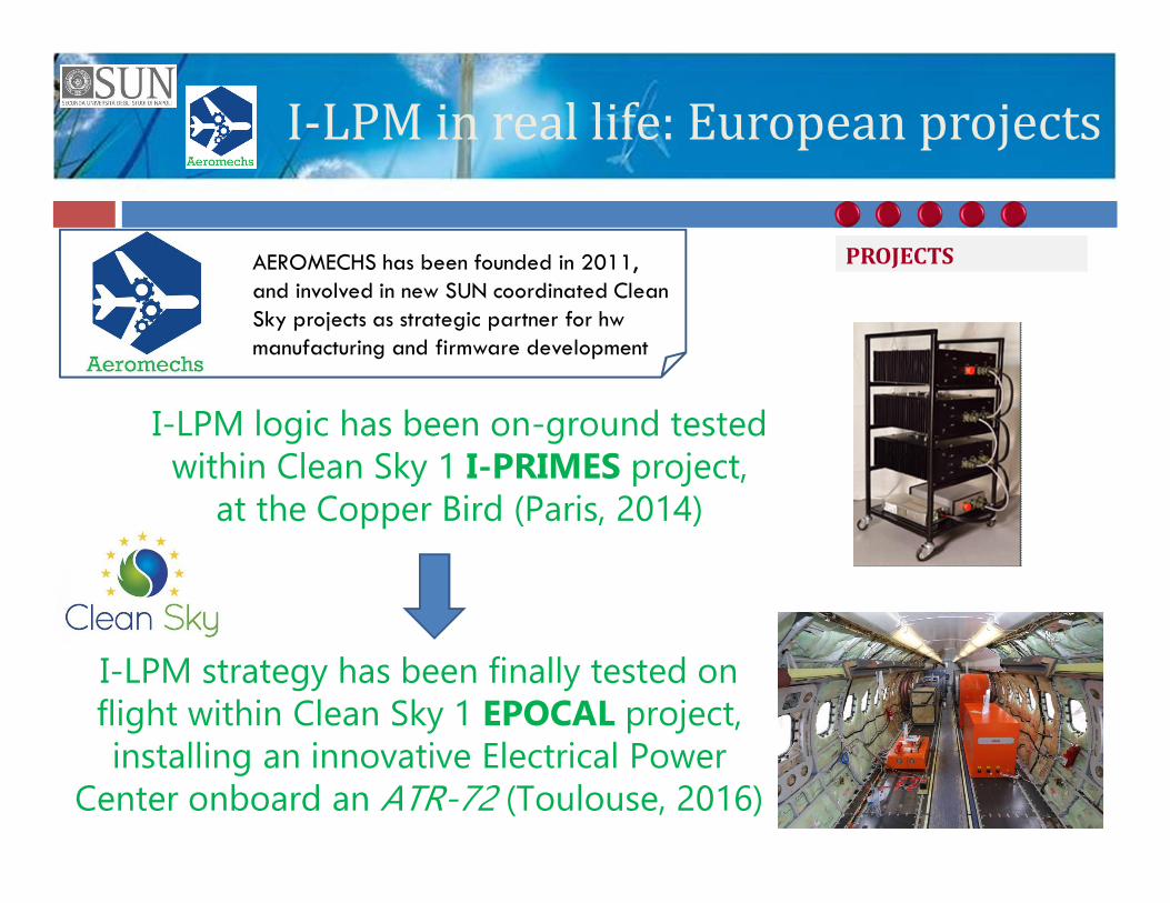
I-LPM in real life: European projectsI-LPM logic has been on-ground tested
within Clean Sky 1 I-PRIMES project, at the Copper Bird (Paris, 2014)
I-LPM strategy has been finally tested on flight within Clean Sky 1 EPOCAL project, installing an innovative Electrical Power
Center onboard an ATR-72 (Toulouse, 2016)
PROJECTSAEROMECHS has been founded in 2011, and involved in new SUN coordinated CleanSky projects as strategic partner for hwmanufacturing and firmware development

Flying for a real Clean Sky!
Thanks for your attention!
A milestone for Green Regional Aircraft and ATR (March 7th, 2016)
http://www.cleansky.eu/content/news/milestone-green-regional-aircraft-and-atr
https://youtu.be/5CuJ9kgoNGU
PROJECTS


![UKCP Supervision Policy - UK Council for Psychotherapy UKCP_Supervision_DocumentAM[3].doc UKCP Supervision Policy Contents 1. Introduction: Generic UKCP Supervision Policy Supervision](https://img.pdfslide.us/doc/110x75/5b42cf1b7f8b9a14058b595a/ukcp-supervision-policy-uk-council-for-psychotherapy-ukcpsupervisiondocumentam3doc.jpg)


![BSMT378 Supervision - Syllabus - Spring 2017 Franco[1] · Supervision Today! Stephen P. Robbins, David A. DeCenzo ... Supervision Challenges Supervision Challenges Planning and Goal](https://img.pdfslide.us/doc/110x75/5b2eba097f8b9a594c8d9060/bsmt378-supervision-syllabus-spring-2017-franco1-supervision-today-stephen.jpg)