Embed Size (px)
Citation preview
Copyright © Claytex Services Limited 2015
Modelling and Simulation Specialists
Multi-Domain Simulation of Hybrid Vehicles
Multiphysics Simulation for Autosport / Motorsport Applications Seminar
UK Magnetics Society
Copyright © Claytex Services Limited 2015
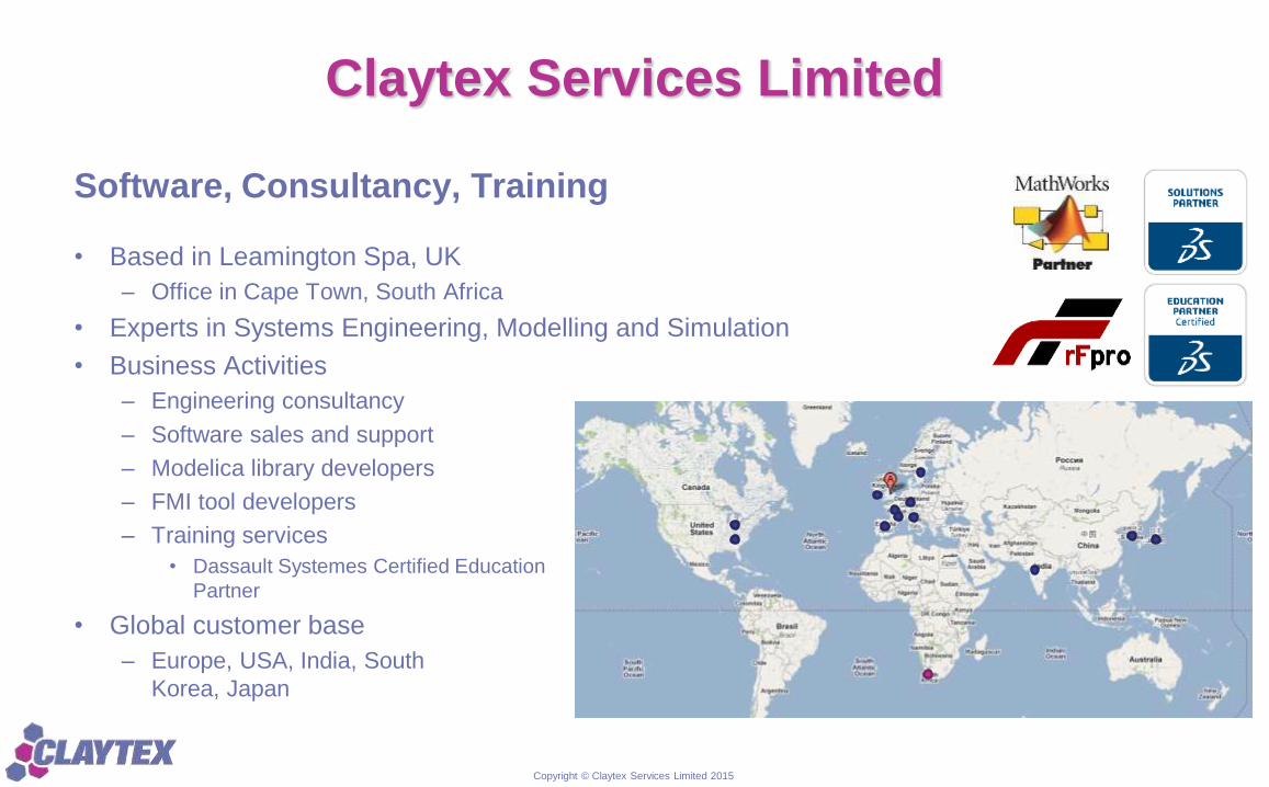
Claytex Services Limited
• Based in Leamington Spa, UK
– Office in Cape Town, South Africa
• Experts in Systems Engineering, Modelling and Simulation
• Business Activities
– Engineering consultancy
– Software sales and support
– Modelica library developers
– FMI tool developers
– Training services
• Dassault Systemes Certified Education
Partner
• Global customer base
– Europe, USA, India, South
Korea, Japan
Software, Consultancy, Training
Copyright © Claytex Services Limited 2015
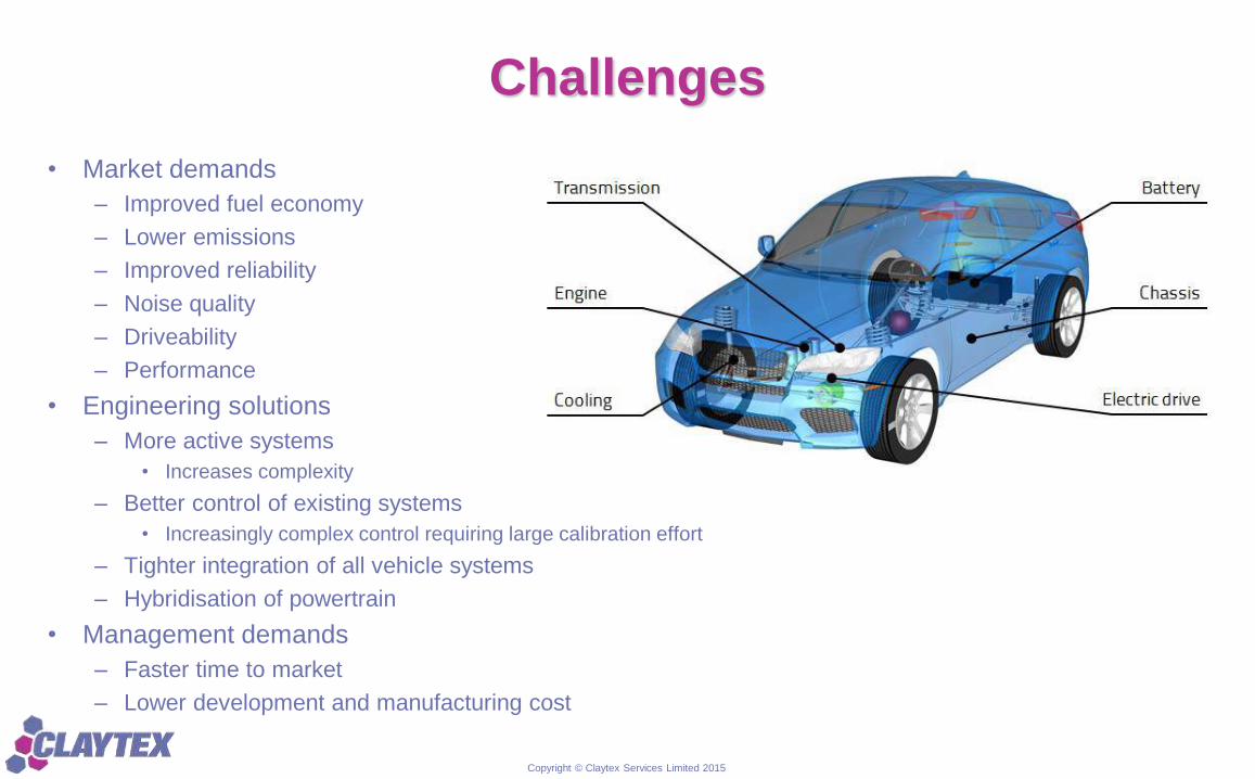
Challenges
• Market demands
– Improved fuel economy
– Lower emissions
– Improved reliability
– Noise quality
– Driveability
– Performance
• Engineering solutions
– More active systems
• Increases complexity
– Better control of existing systems
• Increasingly complex control requiring large calibration effort
– Tighter integration of all vehicle systems
– Hybridisation of powertrain
• Management demands
– Faster time to market
– Lower development and manufacturing cost
Copyright © Claytex Services Limited 2015
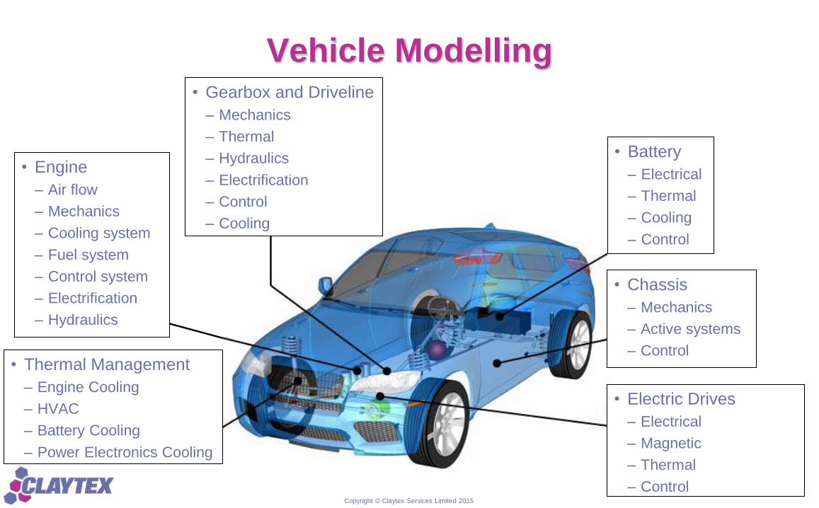
Vehicle Modelling
• Engine
– Air flow
– Mechanics
– Cooling system
– Fuel system
– Control system
– Electrification
– Hydraulics
• Battery
– Electrical
– Thermal
– Cooling
– Control
• Chassis
– Mechanics
– Active systems
– Control• Thermal Management
– Engine Cooling
– HVAC
– Battery Cooling
– Power Electronics Cooling
• Gearbox and Driveline
– Mechanics
– Thermal
– Hydraulics
– Electrification
– Control
– Cooling
• Electric Drives
– Electrical
– Magnetic
– Thermal
– Control
Copyright © Claytex Services Limited 2015
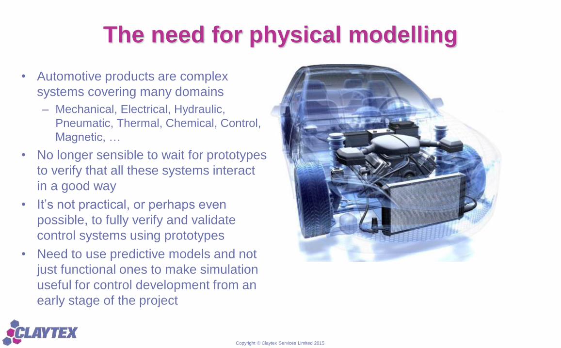
The need for physical modelling
• Automotive products are complex
systems covering many domains
– Mechanical, Electrical, Hydraulic,
Pneumatic, Thermal, Chemical, Control,
Magnetic, …
• No longer sensible to wait for prototypes
to verify that all these systems interact
in a good way
• It’s not practical, or perhaps even
possible, to fully verify and validate
control systems using prototypes
• Need to use predictive models and not
just functional ones to make simulation
useful for control development from an
early stage of the project
Copyright © Claytex Services Limited 2015
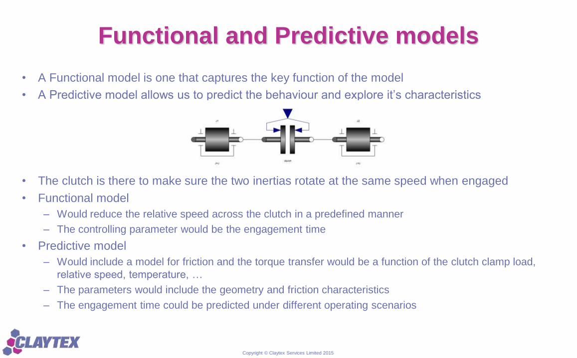
Functional and Predictive models
• A Functional model is one that captures the key function of the model
• A Predictive model allows us to predict the behaviour and explore it’s characteristics
• The clutch is there to make sure the two inertias rotate at the same speed when engaged
• Functional model
– Would reduce the relative speed across the clutch in a predefined manner
– The controlling parameter would be the engagement time
• Predictive model
– Would include a model for friction and the torque transfer would be a function of the clutch clamp load,
relative speed, temperature, …
– The parameters would include the geometry and friction characteristics
– The engagement time could be predicted under different operating scenarios
Copyright © Claytex Services Limited 2015
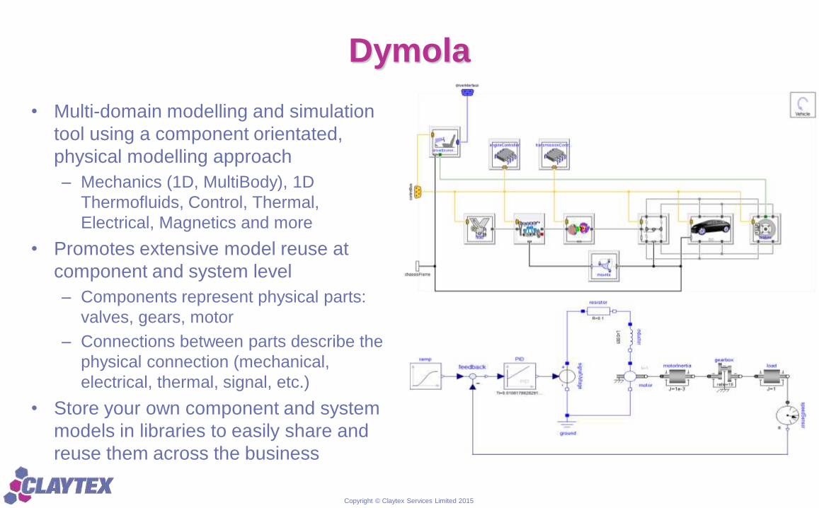
Dymola
• Multi-domain modelling and simulation
tool using a component orientated,
physical modelling approach
– Mechanics (1D, MultiBody), 1D
Thermofluids, Control, Thermal,
Electrical, Magnetics and more
• Promotes extensive model reuse at
component and system level
– Components represent physical parts:
valves, gears, motor
– Connections between parts describe the
physical connection (mechanical,
electrical, thermal, signal, etc.)
• Store your own component and system
models in libraries to easily share and
reuse them across the business
Copyright © Claytex Services Limited 2015
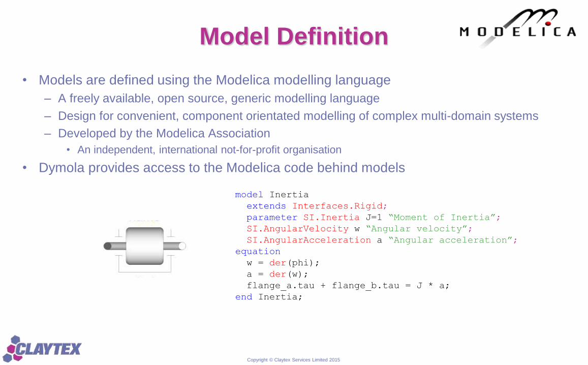
Model Definition
• Models are defined using the Modelica modelling language
– A freely available, open source, generic modelling language
– Design for convenient, component orientated modelling of complex multi-domain systems
– Developed by the Modelica Association
• An independent, international not-for-profit organisation
• Dymola provides access to the Modelica code behind models
model Inertia
extends Interfaces.Rigid;
parameter SI.Inertia J=1 “Moment of Inertia”;
SI.AngularVelocity w “Angular velocity”;
SI.AngularAcceleration a “Angular acceleration”;
equation
w = der(phi);
a = der(w);
flange_a.tau + flange_b.tau = J * a;
end Inertia;
Copyright © Claytex Services Limited 2015
Modelling Magnetics in Dymola
• Two libraries available within the Modelica Standard Library covering magnetics
– FluxTubes
• for modelling of electromagnetic devices with lumped magnetic networks.
• suited for both rough design of the magnetic subsystem of a device as well as for efficient dynamic
simulation at system level together with neighbouring subsystems
• Typical applications are actuators and inductors
– FundamentalWave
• for modelling of electromagnetic fundamental wave models for the application in multi phase electric
machines
• All the machine models provided in this library are equivalent two pole machines. The magnetic
potential difference of the connector therefore also refers to an equivalent two pole machine
• In machines with more than three phases only effects of currents and voltages on the magnetic
fundamental waves are considered
Copyright © Claytex Services Limited 2015
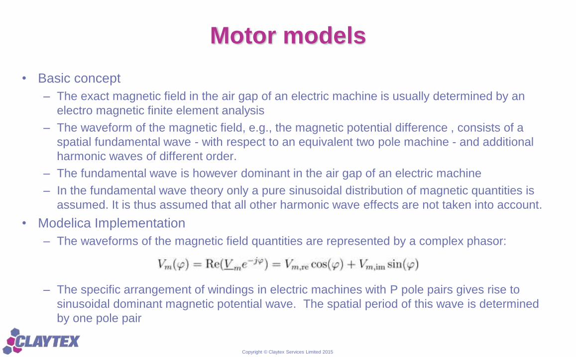
Motor models
• Basic concept
– The exact magnetic field in the air gap of an electric machine is usually determined by an
electro magnetic finite element analysis
– The waveform of the magnetic field, e.g., the magnetic potential difference , consists of a
spatial fundamental wave - with respect to an equivalent two pole machine - and additional
harmonic waves of different order.
– The fundamental wave is however dominant in the air gap of an electric machine
– In the fundamental wave theory only a pure sinusoidal distribution of magnetic quantities is
assumed. It is thus assumed that all other harmonic wave effects are not taken into account.
• Modelica Implementation
– The waveforms of the magnetic field quantities are represented by a complex phasor:
– The specific arrangement of windings in electric machines with P pole pairs gives rise to
sinusoidal dominant magnetic potential wave. The spatial period of this wave is determined
by one pole pair
Copyright © Claytex Services Limited 2015
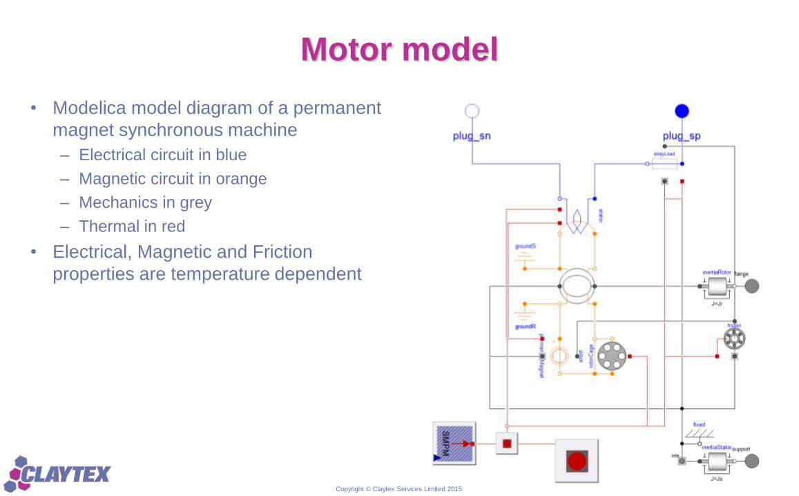
Motor model
• Modelica model diagram of a permanent
magnet synchronous machine
– Electrical circuit in blue
– Magnetic circuit in orange
– Mechanics in grey
– Thermal in red
• Electrical, Magnetic and Friction
properties are temperature dependent
Copyright © Claytex Services Limited 2015
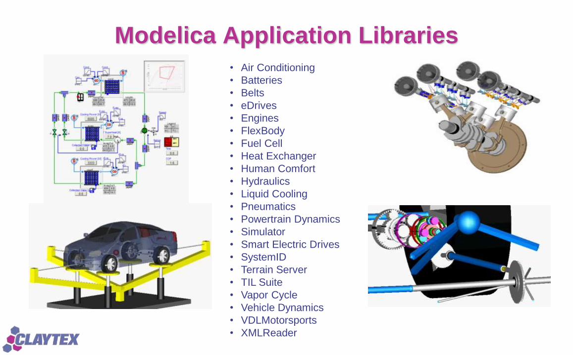
Modelica Application Libraries
• Air Conditioning
• Batteries
• Belts
• eDrives
• Engines
• FlexBody
• Fuel Cell
• Heat Exchanger
• Human Comfort
• Hydraulics
• Liquid Cooling
• Pneumatics
• Powertrain Dynamics
• Simulator
• Smart Electric Drives
• SystemID
• Terrain Server
• TIL Suite
• Vapor Cycle
• Vehicle Dynamics
• VDLMotorsports
• XMLReader
Copyright © Claytex Services Limited 2015
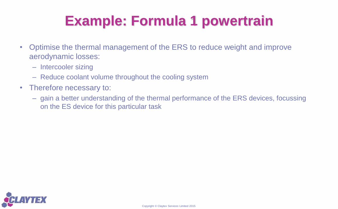
Example: Formula 1 powertrain
• Optimise the thermal management of the ERS to reduce weight and improve
aerodynamic losses:
– Intercooler sizing
– Reduce coolant volume throughout the cooling system
• Therefore necessary to:
– gain a better understanding of the thermal performance of the ERS devices, focussing
on the ES device for this particular task
Copyright © Claytex Services Limited 2015
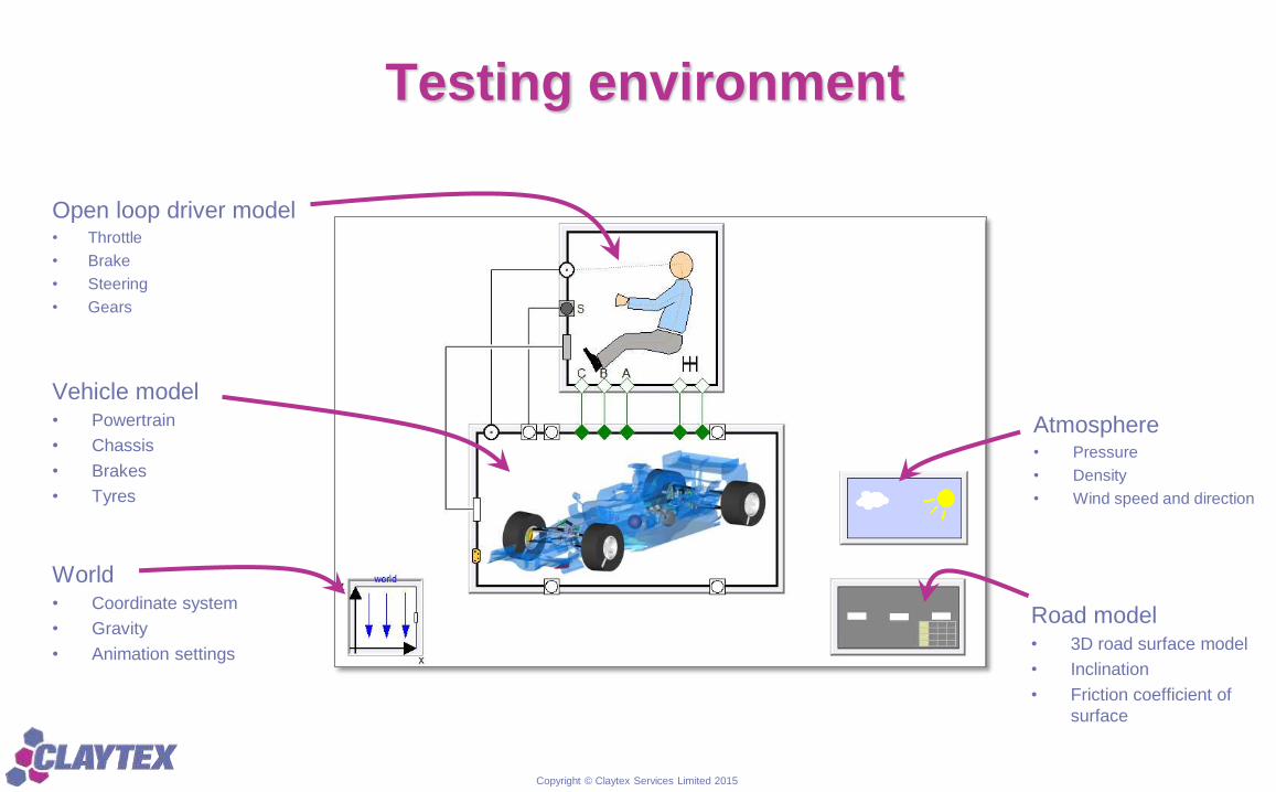
Testing environment
Open loop driver model• Throttle
• Brake
• Steering
• Gears
Atmosphere• Pressure
• Density
• Wind speed and direction
Road model• 3D road surface model
• Inclination
• Friction coefficient of
surface
Vehicle model• Powertrain
• Chassis
• Brakes
• Tyres
World• Coordinate system
• Gravity
• Animation settings
Copyright © Claytex Services Limited 2015
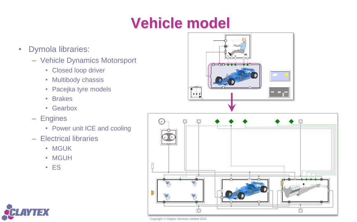
Vehicle model
• Dymola libraries:
– Vehicle Dynamics Motorsport
• Closed loop driver
• Multibody chassis
• Pacejka tyre models
• Brakes
• Gearbox
– Engines
• Power unit ICE and cooling
– Electrical libraries
• MGUK
• MGUH
• ES
Copyright © Claytex Services Limited 2015
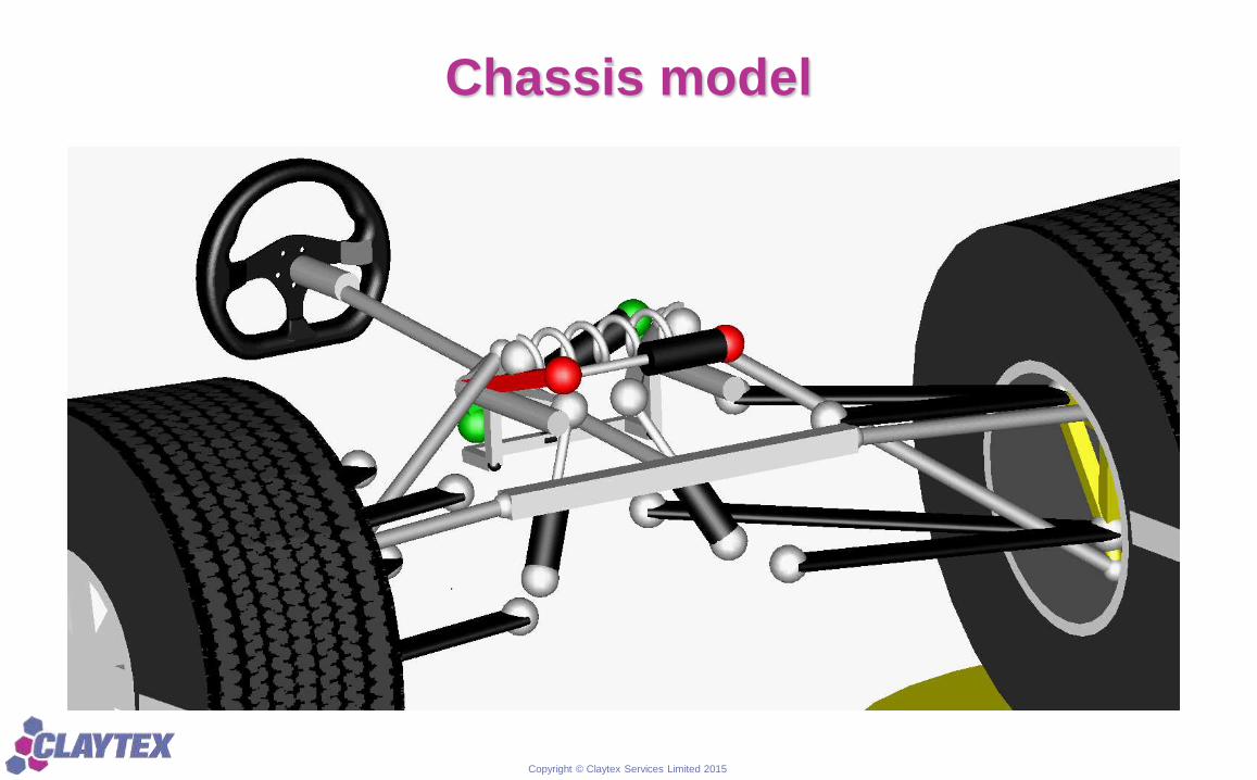
Chassis model
Copyright © Claytex Services Limited 2015
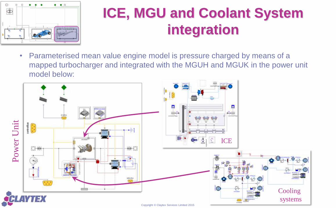
ICE, MGU and Coolant System
integration
• Parameterised mean value engine model is pressure charged by means of a
mapped turbocharger and integrated with the MGUH and MGUK in the power unit
model below:
ICE
Cooling
systems
Pow
er U
nit
Copyright © Claytex Services Limited 2015
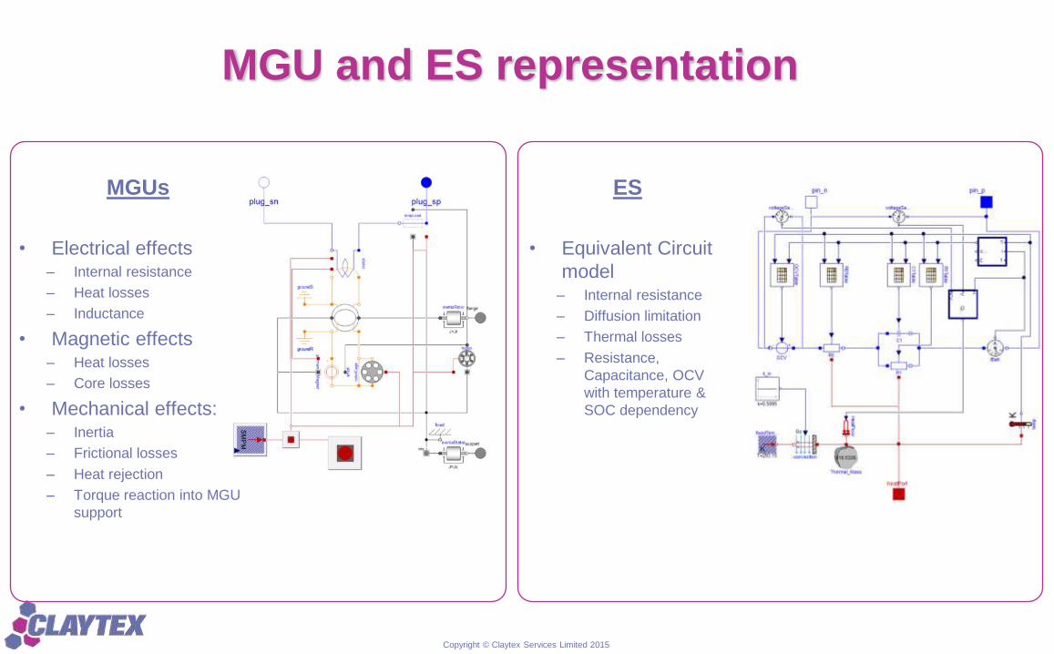
MGU and ES representation
MGUs
• Electrical effects– Internal resistance
– Heat losses
– Inductance
• Magnetic effects– Heat losses
– Core losses
• Mechanical effects:– Inertia
– Frictional losses
– Heat rejection
– Torque reaction into MGU
support
ES
• Equivalent Circuit
model– Internal resistance
– Diffusion limitation
– Thermal losses
– Resistance,
Capacitance, OCV
with temperature &
SOC dependency
Copyright © Claytex Services Limited 2015
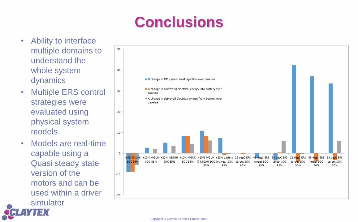
Conclusions• Ability to interface
multiple domains to
understand the
whole system
dynamics
• Multiple ERS control
strategies were
evaluated using
physical system
models
• Models are real-time
capable using a
Quasi steady state
version of the
motors and can be
used within a driver
simulator