Embed Size (px)
Citation preview
Modelling and Simulation of the passive Structure of a5-Axis-Milling Machine with rigid and flexible bodies for
evaluating the static and dynamic behaviour
Michael Schneider, B.Eng.1 Prof. Anton Haumer1 Dipl.-Ing. Rupert Köckeis2
1Faculty of Electrical Engineering and Information Technology , OTH Regensburg, 93053 Regensburg,[email protected], [email protected]
2Department of Electrical Engineering, MAX STREICHER GmbH & Co. KG aA , 94469 Deggendorf,[email protected]
AbstractMost of the mechanical simulations for industrial usageare done by finite element (FE-) analysis. Milling ma-chines are mechatronic systems, combining electrical, me-chanical and control components for machining certainmaterials. Modelica provides a powerful and strong toolto simulate different physical areas in one model. For thisusage a mechanical model of a 5-Axis-Milling Machineis implemented with rigid and flexible bodies. Specificattention will be paid to which components can be mod-elled as rigid bodies without significant deviation in accor-dance to the real behaviour of the machine. Two classesof implementing flexible bodies in multi body systems aregiven by the Flexible Bodies Library, advantages and dis-advantages of both classes will be evaluated. At the enda comparision of the static and dynamic behaviour of thepassive structure of the model in contrast to a FE-analysisis given.Keywords: milling machine, flexible body, multibody sys-tem, clay modelling
1 IntroductionHigh Speed Cutting (HSC) Machines are present in dif-ferent technical areas today. The automotive sector usesHSC-Machines for editing clay models of vehicles to im-prove the design and the aerodynamic behaviour. For thisusage high performance and very high precision is re-quired. The validation of mechanical improvements onexisting machines is expensive and time consuming. Onthe other hand FE-Models can not describe the wholemechatronic system, because the exact influence of theelectrical drive train in mechanic models is described in-sufficiently. For this reason a multyphysical model withan electrical, a mechanical and a control system modelhas to be created. The mechanical model should describethe behaviour of the passive structure in a good approxi-mation. A time efficient model of the machine consistingof rigid and flexible parts without major deviations is de-veloped. During the modelling process several modellingissues have to be solved with particular models.
2 Structure of the Machine
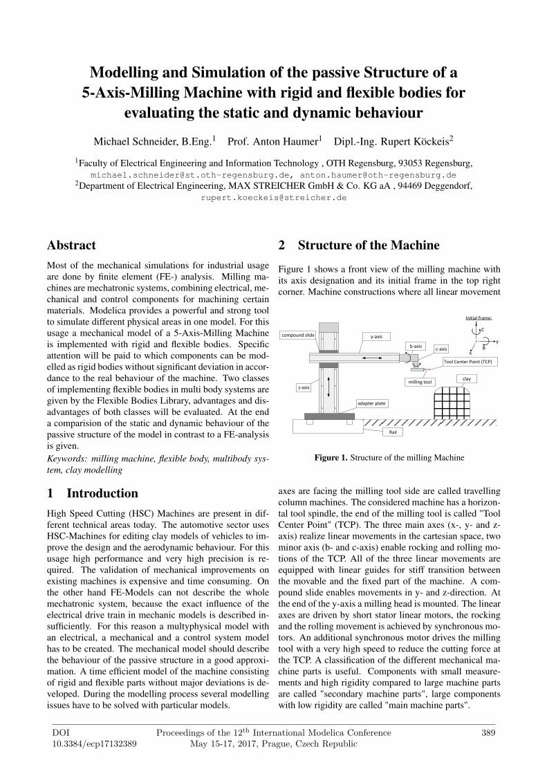
Figure 1 shows a front view of the milling machine withits axis designation and its initial frame in the top rightcorner. Machine constructions where all linear movement
x
y
z
C
B
Initial frame:
y-axis
z-axis
b-axisc-axis
claymilling tool
compound slide
adapter plate
Rail
Tool Center Point (TCP)
Figure 1. Structure of the milling Machine
axes are facing the milling tool side are called travellingcolumn machines. The considered machine has a horizon-tal tool spindle, the end of the milling tool is called "ToolCenter Point" (TCP). The three main axes (x-, y- and z-axis) realize linear movements in the cartesian space, twominor axis (b- and c-axis) enable rocking and rolling mo-tions of the TCP. All of the three linear movements areequipped with linear guides for stiff transition betweenthe movable and the fixed part of the machine. A com-pound slide enables movements in y- and z-direction. Atthe end of the y-axis a milling head is mounted. The linearaxes are driven by short stator linear motors, the rockingand the rolling movement is achieved by synchronous mo-tors. An additional synchronous motor drives the millingtool with a very high speed to reduce the cutting force atthe TCP. A classification of the different mechanical ma-chine parts is useful. Components with small measure-ments and high rigidity compared to large machine partsare called "secondary machine parts", large componentswith low rigidity are called "main machine parts".
DOI10.3384/ecp17132389
Proceedings of the 12th International Modelica ConferenceMay 15-17, 2017, Prague, Czech Republic
389
3 Modelling of the secondary machineparts
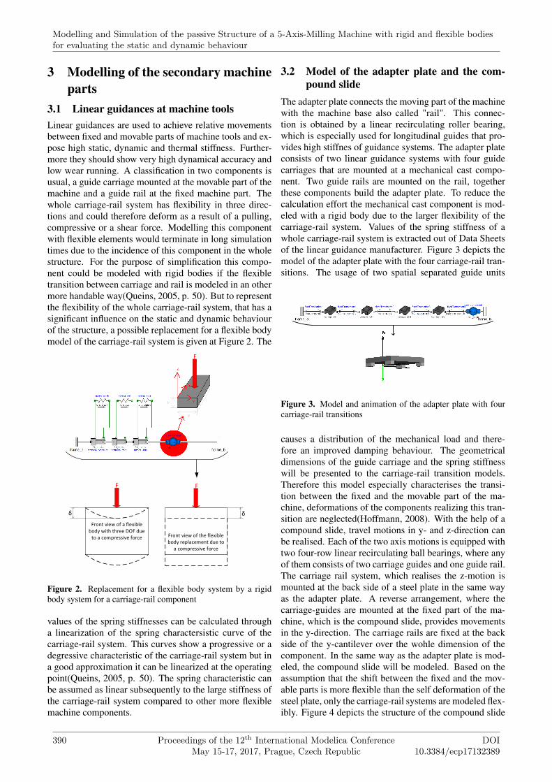
3.1 Linear guidances at machine toolsLinear guidances are used to achieve relative movementsbetween fixed and movable parts of machine tools and ex-pose high static, dynamic and thermal stiffness. Further-more they should show very high dynamical accuracy andlow wear running. A classification in two components isusual, a guide carriage mounted at the movable part of themachine and a guide rail at the fixed machine part. Thewhole carriage-rail system has flexibility in three direc-tions and could therefore deform as a result of a pulling,compressive or a shear force. Modelling this componentwith flexible elements would terminate in long simulationtimes due to the incidence of this component in the wholestructure. For the purpose of simplification this compo-nent could be modeled with rigid bodies if the flexibletransition between carriage and rail is modeled in an othermore handable way(Queins, 2005, p. 50). But to representthe flexibility of the whole carriage-rail system, that has asignificant influence on the static and dynamic behaviourof the structure, a possible replacement for a flexible bodymodel of the carriage-rail system is given at Figure 2. The
Front view of a flexible body with three DOF due
to a compressive force
δ δ
F F
F
starrer KörperFront view of the flexible body replacement due to
a compressive force
Figure 2. Replacement for a flexible body system by a rigidbody system for a carriage-rail component
values of the spring stiffnesses can be calculated througha linearization of the spring charactersistic curve of thecarriage-rail system. This curves show a progressive or adegressive characteristic of the carriage-rail system but ina good approximation it can be linearized at the operatingpoint(Queins, 2005, p. 50). The spring characteristic canbe assumed as linear subsequently to the large stiffness ofthe carriage-rail system compared to other more flexiblemachine components.
3.2 Model of the adapter plate and the com-pound slide
The adapter plate connects the moving part of the machinewith the machine base also called "rail". This connec-tion is obtained by a linear recirculating roller bearing,which is especially used for longitudinal guides that pro-vides high stiffnes of guidance systems. The adapter plateconsists of two linear guidance systems with four guidecarriages that are mounted at a mechanical cast compo-nent. Two guide rails are mounted on the rail, togetherthese components build the adapter plate. To reduce thecalculation effort the mechanical cast component is mod-eled with a rigid body due to the larger flexibility of thecarriage-rail system. Values of the spring stiffness of awhole carriage-rail system is extracted out of Data Sheetsof the linear guidance manufacturer. Figure 3 depicts themodel of the adapter plate with the four carriage-rail tran-sitions. The usage of two spatial separated guide units
Figure 3. Model and animation of the adapter plate with fourcarriage-rail transitions
causes a distribution of the mechanical load and there-fore an improved damping behaviour. The geometricaldimensions of the guide carriage and the spring stiffnesswill be presented to the carriage-rail transition models.Therefore this model especially characterises the transi-tion between the fixed and the movable part of the ma-chine, deformations of the components realizing this tran-sition are neglected(Hoffmann, 2008). With the help of acompound slide, travel motions in y- and z-direction canbe realised. Each of the two axis motions is equipped withtwo four-row linear recirculating ball bearings, where anyof them consists of two carriage guides and one guide rail.The carriage rail system, which realises the z-motion ismounted at the back side of a steel plate in the same wayas the adapter plate. A reverse arrangement, where thecarriage-guides are mounted at the fixed part of the ma-chine, which is the compound slide, provides movementsin the y-direction. The carriage rails are fixed at the backside of the y-cantilever over the wohle dimension of thecomponent. In the same way as the adapter plate is mod-eled, the compound slide will be modeled. Based on theassumption that the shift between the fixed and the mov-able parts is more flexible than the self deformation of thesteel plate, only the carriage-rail systems are modeled flex-ibly. Figure 4 depicts the structure of the compound slide
Modelling and Simulation of the passive Structure of a 5-Axis-Milling Machine with rigid and flexible bodiesfor evaluating the static and dynamic behaviour
390 Proceedings of the 12th International Modelica ConferenceMay 15-17, 2017, Prague, Czech Republic
DOI10.3384/ecp17132389

model with the eight carriage-rail transitions splitted intothe different axis movements and the related 3D-model ofthe component. The animation of the component depicts
Figure 4. Model and animation of the compound slide witheight carriage-rail transitions splitted into the different axismovements
the reversal arrangement of the different linear guide sys-tems. It makes no difference whether the carriage-rail shiftbetween the y-cantilever and the compound slide is mod-eled at the slide itself or at the horizontal cantilever. Inorder to the same reasons as discussed at the adapter plate,only the flexibility of the transitions is modeled, the steelplate is assumed to be rigid.
3.3 Modelling of the Milling HeadThe milling head is mounted at the end of the y-cantilever,it consists of eight parts. All of these parts are used toachieve rotary movements of the milling tool, which ismounted at the end of the component. Different connec-tion flanges combine the rotary axes mechanically witheach other. In comparision with the secondary and espe-cially with the main machine parts the dimensions of thestructural elements of the milling head are small. As a re-sult of this assumption and as the milling head only actsas a load at the end of the y-cantilever the components canbe modeled rigidly. In Figure 5 the model and the ani-mation of the milling head is illustrated. The rotary mo-tions of the different axes are implemented by componentsof the Modelica.Mechanics.Multibody.Joints li-
Figure 5. Model and animation of the milling head with rigidbodies
brary. Different parameters of the rigid components, suchas the mass or geometric dimensions, are defined by de-sign data of the milling head.
4 Modeling of the main machine parts4.1 Modeling of the Y-CantileverThe initial situation at the y-cantilever can be described asfollows, the cantilever is connected to the compound slideby the linear guides as described in section 3.2. It per-forms movements in the YZ-plane due to external forcescaused by a linear direct drive. These forces, the con-nected milling head together with gravitational forces areleading to deformations of the canteliver and therefore torelative movements of the TCP with respect to the initalframe. For this reasons the y-cantilever has to be mod-eled with flexible bodies, and therefore the usage of theFlexibleBodies library is necessary. Choosing bound-ary conditions with respect to this situation would lead tothe following conditions. In Figure 6 above, the initial sit-uation with three choosen boundary conditions (red num-bers) is depicted. The boundary conditions can be chosen
1 2 3
1 2 3 4
cantilever (initial situation)
deformed structure
cantilever (substitude model)
Figure 6. Inital situation of the y-cantilever and substitutedmodel
free at point 1 and 3 and as movable support at number2 because of the parallel guidance at the compound slide.The base class of a beam from the FlexibleBodies li-brary enforces the user to choose boundary conditions foreach deformation type at the endings of the beam to getcorrect results(Dr.-Ing. Andreas Heckmann et al., 2016).It is not possible to choose boundary conditions at cer-tain points within the length of the beam. Choosing thebase class of a beam model with two boundary condi-tions for each deformation type would therefore lead tolarge errors due to neglecting the third boundary condi-tion. Furthermore the point, where the beam is movablysupported changes during the milling process. In orderto minimize the realtive error of the y-cantilever model asubstitude model (Figure 6 bottom) has to be created. Themodel is splitted into three parts, where two parts consistsof flexible beams (Figure 6 black) and one part is a rigid
Session 6: Poster Session
DOI10.3384/ecp17132389
Proceedings of the 12th International Modelica ConferenceMay 15-17, 2017, Prague, Czech Republic
391
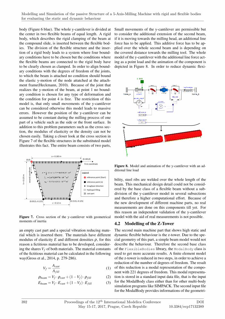
body (Figure 6 blue). The whole y-cantilever is divided atthe center in two flexible beams of equal length. A rigidbody, which describes the rigid clamping of the beam atthe compound slide, is inserted between the flexible bod-ies. The division of the flexible structure and the inser-tion of a rigid body leads to a system where four bound-ary conditions have to be chosen but the conditions wherethe flexible beams are connected to the rigid body haveto be clearly chosen as clamped. In order to align bound-ary conditions with the degrees of freedom of the joints,to which the beam is attached no condition should boundthe elastic y-motion of the node attatched at the attach-ment frame(Heckmann, 2010). Because of the joint thatrealizes the y-motion of the beam, at point 1 no bound-ary condition is chosen for any type of deformation andthe condition for point 4 is free. The restricition of thismodel is, that only small movements of the y-cantilevercan be considered otherwise this model leads to massiveerrors. However the position of the y-cantilever can beassumed to be constant during the milling process of onepart of a vehicle such as the side or the front surface. Inaddition to this problem parameters such as the cross sec-tion, the modulus of elasticity or the density can not bechosen easily. Taking a closer look at the cross section inFigure 7 of the flexible structures in the substituted modelillustrates this fact. The entire beam consists of two parts,
{0,0} {0.183,0}
{0.1515,-0.125}{0.0315,-0.125}
First coordinate
seco
nd
co
ord
inat
e
a = 0.183 m
c = 0.12 m
h =
0.1
25
m
reference point (Start)
reference point (n)
troughput direction
Hydropol-filling
cast part
Figure 7. Cross section of the y-cantilever with geometricalmoments of inertia
an empty cast part and a special vibration reducing mate-rial which is inserted there. The materials have differentmodulus of elasticity E and different densities ρ , for thisreason a fictitious material has to be developed, consider-ing the shares Vf of both materials. The material constantsof the fictitious material can be calculated in the followingway(Gross et al., 2014, p. 279-286).
Vf =Acast
A f ill(1)
ρbeam =Vf ·ρcast +(1−Vf ) ·ρ f ill (2)Ebeam =Vf ·Ecast +(1−Vf ) ·E f ill (3)
Small movements of the y-cantilever are permissible butto consider the additional extension of the second beam,if it is moving towards the milling head, an additional lineforce has to be applied. This additive force has to be ap-plied over the whole second beam and is depending onthe covered distance towards the milling tool. The wholemodel of the y-cantilever with the additional line force act-ing as a point load and the animation of the component isdepicted in Figure 8. In order to reduce dynamic flexi-
Figure 8. Model and animation of the y-cantilever with an ad-ditional line load
bility, steel ribs are welded over the whole length of thebeam. This mechanical design detail could not be consid-ered by the base class of a flexible beam without a sub-division of the y-cantilever model in several subsectionsand therefore a higher computational effort. Because ofthe new development of different machine parts, no realmeasurements are done on this components till yet. Forthis reason an independent validation of the y-cantilevermodel with the aid of real measurements is not possible.
4.2 Modelling of the Z-TowerThe second main machine part that shows high static anddynamic flexible behaviour is the z-tower. Due to the spe-cial geometry of this part, a simple beam model would notdescribe the behaviour. Therefore the second base classof the FlexibleBodies library, the ModalBody class isused to get more accurate results. A finite element modelof the z-tower is reduced in two steps, in order to achieve areduction of the number of degrees of freedom. The resultof this reduction is a modal representation of the compo-nent with 221 degrees of freedom. This modal representa-tion is stored in a standard input data file, that is the inputfor the ModalBody class either than for other multi-bodysimulation programs like SIMPACK. The second input filefor the ModalBody provides informations of the geometri-
Modelling and Simulation of the passive Structure of a 5-Axis-Milling Machine with rigid and flexible bodiesfor evaluating the static and dynamic behaviour
392 Proceedings of the 12th International Modelica ConferenceMay 15-17, 2017, Prague, Czech Republic
DOI10.3384/ecp17132389
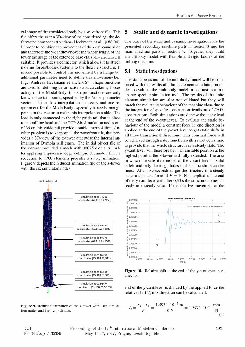
cal shape of the considered body by a wavefront file. Thisfile offers the user a 3D-view of the considered eg. the de-formated component(Andreas Heckmann et al., p.88-94).In order to combine the movement of the compound slideand therefore the y-cantilever over the whole length of thetower the usage of the extended base class MovingLoad issuitable. It provides a connector, which allows it to attachmoving forces/bodies/systems to the flexible structure. Itis also possible to control this movement by a flange butadditional parameter need to define this movement(Dr.-Ing. Andreas Heckmann et al., 2016). Shape functionsare used for defining deformations and calculating forcesacting on the ModalBody, this shape functions are onlyknown at certain points, specified by the Nodes parametervector. This makes interpolation necessary and one re-quirement for the ModalBody especially it needs enoughpoints in the vector to make this interpolation stable. Theload is only connected to the right guide rail that is closeto the milling head and the TCP. Six Simulation nodes outof 36 on this guide rail provide a stable interpolation. An-other problem is to keep small the wavefront file, that pro-vides a 3D-view of the z-tower otherwise the internal an-imation of Dymola will crash. The initial object file ofthe z-tower provided a mesh with 30095 elements. Af-ter applying a quadratic edge collapse decimaton filter areduction to 1700 elements provides a stable animation.Figure 9 depicts the reduced animation file of the z-towerwith the six simulaton nodes.
simulation node 77710 coordinates {65,118.83,2859}
simulation node 82440 coordinates {65,118.83,1900}
simulation node 84378 coordinates {65,118.83,1501}
simulation node 87098 coordinates {65,118.83,941}
simulation node 89818 coordinates {65,118.83,381}
simulation node 91474 coordinates {65,118.83,58.89}
right guidance rail
Figure 9. Reduced animation of the z-tower with used simual-tion nodes and their coordinates
5 Static and dynamic investigationsThe basis of the static and dynamic investigations are thepresented secondary machine parts in section 3 and themain machine parts in section 4. Together they builda multibody model with flexible and rigid bodies of themilling machine.
5.1 Static investigations
The static behaviour of the multibody model will be com-pared with the results of a finite element simulation in or-der to evaluate the multibody model in contrast to a me-chanic specific simulation tool. The results of the finiteelement simulation are also not validated but they willmatch the real static behaviour of the machine close due tothe integration of specific construction details out of CAD-constructions. Both simulations are done without any loadat the end of the y-cantilever. To evaluate the static be-haviour of the model a constant force in one direction isapplied at the end of the y-cantilever to get static shifts inall three translational directions. This constant force willbe achieved through a step function with a short delay timeto provide that the whole structure is in a steady state. They-cantilever will therefore be in an unstable position at thehighest point at the z-tower and fully extended. The areain which the substitute model of the y-cantilever is validis left and only the magnitudes of the static shifts can berated. After five seconds to get the structure in a steadystate, a constant force of F = 10 N is applied at the endof the y-cantilever and after 0,35 s the structure comes al-ready to a steady state. If the relative movement at the
4.8256 4.8956 4.9656 5.0356 5.1056 5.1756 5.2456 5.3156 5.3856
Time [s]
2.7382401
2.7382431
2.7382461
2.7382491
2.7382521
2.7382551
2.7382581
2.7382611
2.7382641
2.7382671
2.7382701
2.7382731
2.7382761
2.7382785
rela
tive
shift
at t
he e
nd o
f the
y-c
antil
ever
in z
-dire
ctio
n [m
]
Relative shift in z-direction
z-position at the end of the y-cantilever
z1
z2
Figure 10. Relative shift at the end of the y-cantilever in z-direction
end of the y-cantilever is divided by the applied force therelative shift Vz in z-direction can be calculated.
Vz =z2 − z1
F=
1.5974 ·10−5 m10 N
= 1.5974 ·10−3 mmN
(4)
Session 6: Poster Session
DOI10.3384/ecp17132389
Proceedings of the 12th International Modelica ConferenceMay 15-17, 2017, Prague, Czech Republic
393
In the same way as shown above the relative shifts in y-and x-direction can be calculated.
Vy =y2 − y1
F=
1.0729 ·10−5 m10 N
= 1.0729 ·10−3 mmN
(5)
Vx =x2 − x1
F=
5.9605 ·10−6 m10 N
= 5.9605 ·10−4 mmN
(6)
Comparing the results of the multibody simulation to thefinite element solutions it can be stated that in a good ap-proximation they are convergent. Deviations can be justi-fied by the neglection of the flexibility of the guidance sys-tem, the disregardence of the ribs in the y-cantilever andthe desertion of the scope of the y-cantilever. Regardingthe magnitudes of the static shifts it can be said that theyare absolutely convergent to the finite element solution.
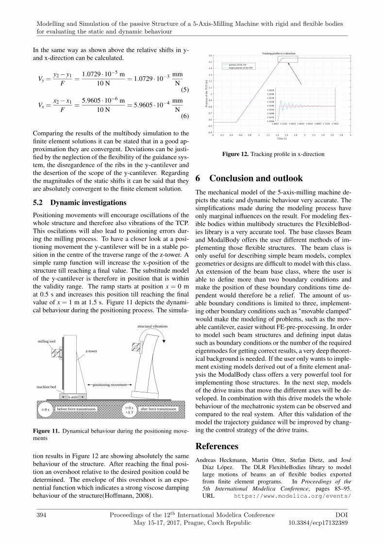
5.2 Dynamic investigationsPositioning movements will encourage oscillations of thewhole structure and therefore also vibrations of the TCP.This oscilations will also lead to positioning errors dur-ing the milling process. To have a closer look at a posi-tioning movement the y-cantilever will be in a stable po-sition in the centre of the traverse range of the z-tower. Asimple ramp function will increase the x-position of thestructure till reaching a final value. The substitude modelof the y-cantilever is therefore in position that is withinthe validity range. The ramp starts at position x = 0 mat 0.5 s and increases this position till reaching the finalvalue of x = 1 m at 1.5 s. Figure 11 depicts the dynami-cal behaviour during the positioning process. The simula-
structural vibrations
before force transmission t=0 s
+Δ Tafter force transmissiont=0 s
x-axis
positioning movement
z-tower
milling tool
machine bed
Figure 11. Dynamical behaviour during the positioning move-ments
tion results in Figure 12 are showing absolutely the samebehaviour of the structure. After reaching the final posi-tion an overshoot relative to the desired position could bedetermined. The envelope of this overshoot is an expo-nential function which indicates a strong viscose dampingbehaviour of the structure(Hoffmann, 2008).
0 0.2 0.4 0.6 0.8 1 1.2 1.4 1.6 1.8 2 2.2 2.4 2.6 2.8 3
Time [s]
0.4
0.5
0.6
0.7
0.8
0.9
1
1.1
1.2
1.3
1.4
1.5
1.6
Po
siti
on o
f th
e T
CP
[m
]
Tracking profile in x-direction
position of the TCP
target position of the TCP
1.4822 1.5222 1.5622 1.6022 1.6422 1.6822 1.7222 1.76221.5458
1.5478
1.5498
1.5518
1.5538
1.5558
1.5578
1.5598
1.5618
Figure 12. Tracking profile in x-direction
6 Conclusion and outlookThe mechanical model of the 5-axis-milling machine de-picts the static and dynamic behaviour very accurate. Thesimplifications made during the modeling process haveonly marginal influences on the result. For modeling flex-ible bodies within multibody structures the FlexibleBod-ies library is a very accurate tool. The base classes Beamand ModalBody offers the user different methods of im-plementing those flexible structures. The beam class isonly useful for describing simple beam models, complexgeometries or designs are difficult to model with this class.An extension of the beam base class, where the user isable to define more than two boundary conditions andmake the position of these boundary conditions time de-pendent would therefore be a relief. The amount of us-able boundary conditions is limited to three, implement-ing other boundary conditions such as "movable clamped"would make the modeling of problems, such as the mov-able cantilever, easier without FE-pre-processing. In orderto model such beam structures and defining input datassuch as boundary conditions or the number of the requiredeigenmodes for getting correct results, a very deep theoret-ical background is needed. If the user only wants to imple-ment existing models derived out of a finite element anal-ysis the ModalBody class offers a very powerful tool forimplementing those structures. In the next step, modelsof the drive trains that move the different axes will be de-veloped. In combination with this drive models the wholebehaviour of the mechatronic system can be observed andcompared to the real system. After this validation of themodel the trajectory guidance will be improved by chang-ing the control strategy of the drive trains.
ReferencesAndreas Heckmann, Martin Otter, Stefan Dietz, and José
Díaz López. The DLR FlexibleBodies library to modellarge motions of beams an of flexible bodies exportedfrom finite element programs. In Proceedings of the5th International Modelica Conference, pages 85–95.URL https://www.modelica.org/events/
Modelling and Simulation of the passive Structure of a 5-Axis-Milling Machine with rigid and flexible bodiesfor evaluating the static and dynamic behaviour
394 Proceedings of the 12th International Modelica ConferenceMay 15-17, 2017, Prague, Czech Republic
DOI10.3384/ecp17132389

modelica2006/Proceedings/proceedings/Proceedings2006_Vol1.pdf.
Dr.-Ing. Andreas Heckmann, Prof. Dr.-Ing. Martin Otter, MartinLeitner, Jakub Tobolar, and Stefan Hartweg. FlexibleBod-ies: Library to model large motions of flexible beams, anularplates and of flexible bodies exported from finite element pro-grams, 2016. Version 2.2.
Dietmar Gross, Werner Hauger, Jörg Schröder, and Wolfgang A.Wall. Technische Mechanik 2: Elastostatik. Springer-Lehrbuch. Springer Vieweg, Berlin, 12., aktual. aufl. edi-tion, 2014. ISBN 978-3-642-40965-3. doi:10.1007/978-3-642-40966-0. URL http://dx.doi.org/10.1007/978-3-642-40966-0.
Andreas Heckmann. On the choice of boundary conditionsfor mode shapes in flexible multibody systems. MultibodySystem Dynamics, 23(2):141–163, 2010. ISSN 1384-5640.doi:10.1007/s11044-009-9177-z.
Frank Hoffmann. Optimierung der dynamischen Bahnge-nauigkeit von Werkzeugmaschinen mit der Mehrkörpersimu-lation: Zugl.: Aachen, Techn. Hochsch., Diss., 2008, volume2008,8 of Ergebnisse aus der Produktionstechnik Werkzeug-maschinen. Apprimus-Verl., Aachen, 2008. ISBN 978-3-940565-12-9.
Marcus Queins. Simulation des dynamischen Verhaltens vonWerkzeugmaschinen mit Hilfe flexibler Mehrkörpermodelle:Zugl.: Aachen, Techn. Hochsch., Diss., 2005, volume2005,12 of Berichte aus der Produktionstechnik. Shaker,Aachen, 2005. ISBN 3-8322-4224-4.
Session 6: Poster Session
DOI10.3384/ecp17132389
Proceedings of the 12th International Modelica ConferenceMay 15-17, 2017, Prague, Czech Republic
395