Embed Size (px)
Citation preview
MODELLING AND ANALYSIS OF THE ENHANCED TAPP SCHEME FOR
DISTRIBUTION NETWORKS
Maciej Fila Brunel University/EDF Energy, UK
Gareth A. Taylor Brunel Institute of Power Systems
Brunel University, UK
Peter Lang EDF Energy, UK
Jonathan Hiscock Fundamentals Ltd
Long Crendon, UK
Malcolm R. Irving Brunel Institute of Power Systems
Brunel University, UK
Abstract - At present the main aim for
Distribution Network Operators (DNOs) is to
develop flexible, reliable and efficient networks, in
order to enable the connection of distributed
generation. Active control of distribution networks
is a feasible solution in order to reach that aim. One
of the first and most commonly used active control
devices is an on-load tap changer (OLTC) with its
automatic voltage control (AVC) relay. Even
though this technique for voltage control is well
established, traditional AVC schemes can be
unreliable particularly when the transformer
arrangement is complex and conditions of the
network variable. The main factors that undermine
the performance of AVC schemes are; intermittent
output of distributed generation, varying power
factor, difference in primary voltage or non-
identical paralleled transformers. The Enhanced
TAPP scheme can operate efficiently under the
above conditions. The first objective of this paper is
to present principles of the Enhanced TAPP scheme
and mathematical models for AVC schemes in
general. Then the functionality of this scheme will
be demonstrated using software simulation for a
range of distribution network case studies based
upon realistic EDF Energy network scenarios.
Results from the modelling and analysis of the
Enhanced TAPP scheme and conclusions are also
finally presented.
Keywords: advanced voltage control, parallel
transformer, TAPP scheme, distribution
network, voltage control relay
1 INTRODUCTION
Distribution Network Operators (DNOs) are
obliged to maintain voltage profile across the
networks within certain limits. These restrictions
are due to system constraints such as insulation
stresses but mainly due to statutory voltage limits
defined in the Electricity Safety, Quality and
Continuity Regulations 2002 (ESQC). Each
customer in the UK connected to LV network
needs to be supplied at 400/230 V with the
tolerance +10/-6% whereas HV customers (11kV
and 6.6kV) with the tolerance +/-6%. To satisfy
these requirements on-load tap changers (OLTC)
are used to produce appropriate output voltage
under dynamic load conditions and various supply
voltages as well as to reduce circulating current
when transformers run in parallel. To simplify,
automate and optimise performance of the
OLTC’s, automatic voltage control (AVC)
schemes are used.
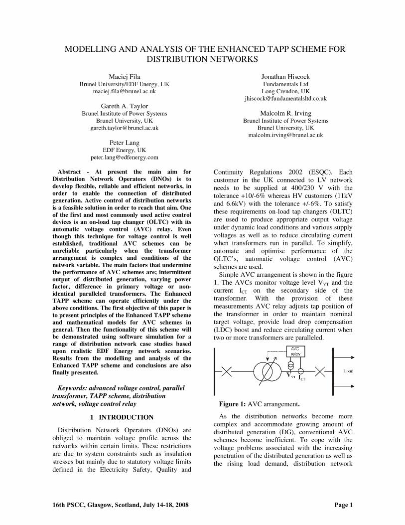
Simple AVC arrangement is shown in the figure
1. The AVCs monitor voltage level VVT and the
current ICT on the secondary side of the
transformer. With the provision of these
measurements AVC relay adjusts tap position of
the transformer in order to maintain nominal
target voltage, provide load drop compensation
(LDC) boost and reduce circulating current when
two or more transformers are paralleled.
Figure 1: AVC arrangement.
As the distribution networks become more
complex and accommodate growing amount of
distributed generation (DG), conventional AVC
schemes become inefficient. To cope with the
voltage problems associated with the increasing
penetration of the distributed generation as well as
the rising load demand, distribution network
16th PSCC, Glasgow, Scotland, July 14-18, 2008 Page 1
operators need more reliable and effective voltage
control devices.
The primary objective of this paper is to
investigate performance of the innovative AVC
relay SuperTAPP n+ and identify appropriate
voltage strategies for the distribution networks
with DG under varying load conditions.
This paper continues and completes the
introductory research study presented by the same
authors in [1], by extending the computer model
and analysis of the Transformer Automatic
Paralleling Package (TAPP) scheme and its
successor the Enhanced TAPP scheme with
distributed generation and load exclusion
functionality.
The paper structure is as follows. Section 2
describes common AVC schemes used in
distribution networks and their characteristics.
Section 3 presents a detailed model of the
Enhanced TAPP scheme and its principles as well
as distributed generation estimation technique and
the load exclusion functionality. Section 4
analyses voltage profile of the network under
various load and DG output conditions and AVC
performance. The results obtained from
simulation are presented. Finally, conclusions are
stated in Section 5.
2 REVIEW OF EXISTING AVC SCHEMES
In order to meet the engineering
recommendation for the security of supply and for
the higher reliability of supply, it is common
practice in distribution networks to parallel
transformers on one site or across the network.
Under such system configurations another aim of
AVC schemes is to keep transformers at a desired
tap position in order to minimise circulating
current and prevent transformers from run away
tapping. Negative Reactance Compounding, True
Circulating Current, Master-Follower and TAPP
are standard voltage control schemes for parallel
transformers. There are several factors affecting
performance of the AVCs such as varying power
factor, presence of the DG (intermittent output),
difference in primary voltage or dissimilar
transformer impedances. Following section
presents advantages and weaknesses of the most
common AVC schemes under varying load
condition and network configuration.
2.1 Negative Reactance Compounding
One of the most common AVC schemes in the
distribution networks is Negative Reactance
Compounding (NRC) technique. NRC was
introduced to distribution networks in the 1960s
due to deficiencies of the Master-Follower
scheme. It uses LDC settings with the negative
value of reactance. The relationship between LDC
settings and NRC setting can be defined as
follows:
LDCLDCLDC jXRZ += (1)
LDCLDCNRC jXRZ −= (2)
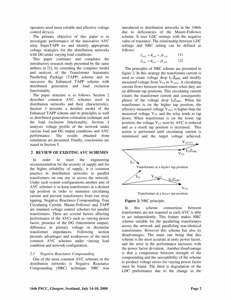
The principles of NRC scheme are presented in
figure 2. In this strategy the transformer current is
used to create voltage drop IT·ZNRC and modify
measured voltage from VVT to VAVC. A circulating
current flows between transformers when they are
on different tap positions. This circulating current
rotates the transformer current and consequently
phasor of the voltage drop ITZNRC. When the
transformer is on the higher tap position, the
effective measured voltage VAVC is higher than the
measured voltage VVT and the relay tends to tap
down. When transformer is on the lower tap
position, the voltage VVT seen by AVC is reduced
and as a result tap position is increased. This
action is performed until circulating current is
minimised and the target voltage achieved.
Figure 2: NRC principle.
In this scheme connections between
transformers are not required as each AVC is able
to act independently. This feature makes NRC
scheme suitable for the paralleling transformers
across the network and paralleling non-identical
transformers. However this scheme has also its
disadvantages. The main one being that this
scheme is the most accurate at unity power factor,
and the error in the performance increases with
the power factor deviation. Another disadvantage
is that a compromise between strength of the
compounding and the susceptibility of the scheme
to produce voltage errors for varying power factor
must be found. The third is degradation of the
LDC performance due to the change in the
IT1
VVT IT1ZNRC
VAVCT1
Transformer at a higher tap position
VVT
IT2 VAVCT2
Transformer at a lower tap position
IT2ZNRC
16th PSCC, Glasgow, Scotland, July 14-18, 2008 Page 2

polarity of the XLDC setting. To keep the same
boost, the value of RLDC must be increased [2].
2.2 Master-Follower
Another AVC scheme used by DNOs is master-follower. One of the parallel transformers
in the scheme monitors the voltage at the bus-bar
and adjusts tap position to provide desirable
voltage level. When master transformer finishes
the action all other transformers in the scheme
replicate it.
The scheme might be used along with LDC and
while settings are adjusted properly, the master-
follower scheme operates correctly under varying
power factor, reverse power flow and with
presence of distributed generation. However,
because connection between relays is required, it
is impractical to use this scheme to parallel
transformers across a network. Complex
switching is needed when one of the transformers
is taken out. Additionally, circulating current will
flow between paralleled transformers using this
scheme unless the transformers are identical, such
that they have the same impedance, number of
taps and incoming voltage [1].
2.3 True Circulating Current
The true circulating current scheme can be used in
order to control voltage at the bus-bar, eliminate
circulating current between transformers and
prevent transformers from run away tapping. In
this scheme interconnection between controllers is
used to deduce transformers currents in order to
calculate circulating current( )
2
21 TT
CIRC
III
−= (3)
For the transformer on the higher tap, ICIRC has a
positive sign, whereas on the lower tap it is
negative. ICIRC is used to create a voltage bias
which adjusts the relay target voltage such that
circulating current is minimised (e.g. transformer
on the higher tap position taps down).
Similar to the master-follower scheme, true
circulating current might be used with LDC and it
operates correctly under varying power factor,
reverse power flow and with presence of
distributed generation. Likewise, this scheme has
disadvantages such as:
- difficulty with paralleling transformers across
the network,
- necessary connection rearrangement while
taking one of the transformers within the
scheme out of service,
- transformers must be similar (impedance,
incoming voltage, connections),
- Inaccurate LDC in the presence of embedded
generator output.
2.4 TAPP scheme:
TAPP scheme is based on the negative
reactance compounding principle [3]. However in
this scheme two separate circuits are used, one for
the purpose of LDC and one for the purpose of
compounding, in order to eliminate the need of
trade-off between strength of the compounding
and the susceptibility to produce voltage errors for
varying power factor. Additionally this scheme
effectively reduces circulating current, which can
flow between parallel transformers, using
numerical techniques based on the target power
factor. Circulating current in the TAPP method is
evaluated by comparing the measured transformer
load current (ITR) with the target power factor
(pftarg) as is shown in figure 3.
One disadvantage of the TAPP scheme is the
incurred voltage error as the load power factor
deviates from the set power factor. This is because
circulating current is considered a part of the load
current. This drawback is eliminated in Enhanced
TAPP scheme [3, 4].
Figure 3: Principles of TAPP scheme.
All the above AVC schemes have a common
drawback associated with the presence of DG.
This is because the voltage and current
measurements fed to the relay are taken locally as
shown in figure 1. Therefore, the AVC schemes
are unable to act appropriately when a voltage
increase occurs, at a remote point of the feeder as
a consequence of the presence of DG.
3 ENHANCED TAPP SCHEME AND
SuperTAPP n+ FUNCTIONALITY
There are several proposed solutions to improve
voltage profile in distribution networks with DG.
Solutions such as network reinforcements, line re-
conducting, building a dedicated line are currently
available and used in distribution networks.
Active voltage control with remote voltage
pftarget
ICIRC
VVT
ITR
β α
16th PSCC, Glasgow, Scotland, July 14-18, 2008 Page 3
sensing units (i.e. GenAVC), line voltage
regulation, scheduling of distributed generation
and several other techniques are still in
development and trial.
The SuperTAPP n+ relay offers firstly, very
effective AVC performance based on the
Enhanced TAPP algorithm, secondly the
innovative technique for voltage control in the
distribution network with DG. The key benefit of
this scheme is that all measurements are taken
locally and there is no need for remote
communication with the generators.
To ensure effective voltage control at the
substation, to which DG is connected, the AVC
relay must be resistant to the intermittent
character of the DG and varying power factor of
the network. Enhanced TAPP scheme fulfils these
criteria as demonstrated in the [1]. This scheme is
the combination of the TAPP and Circulating
Current methods bringing together their
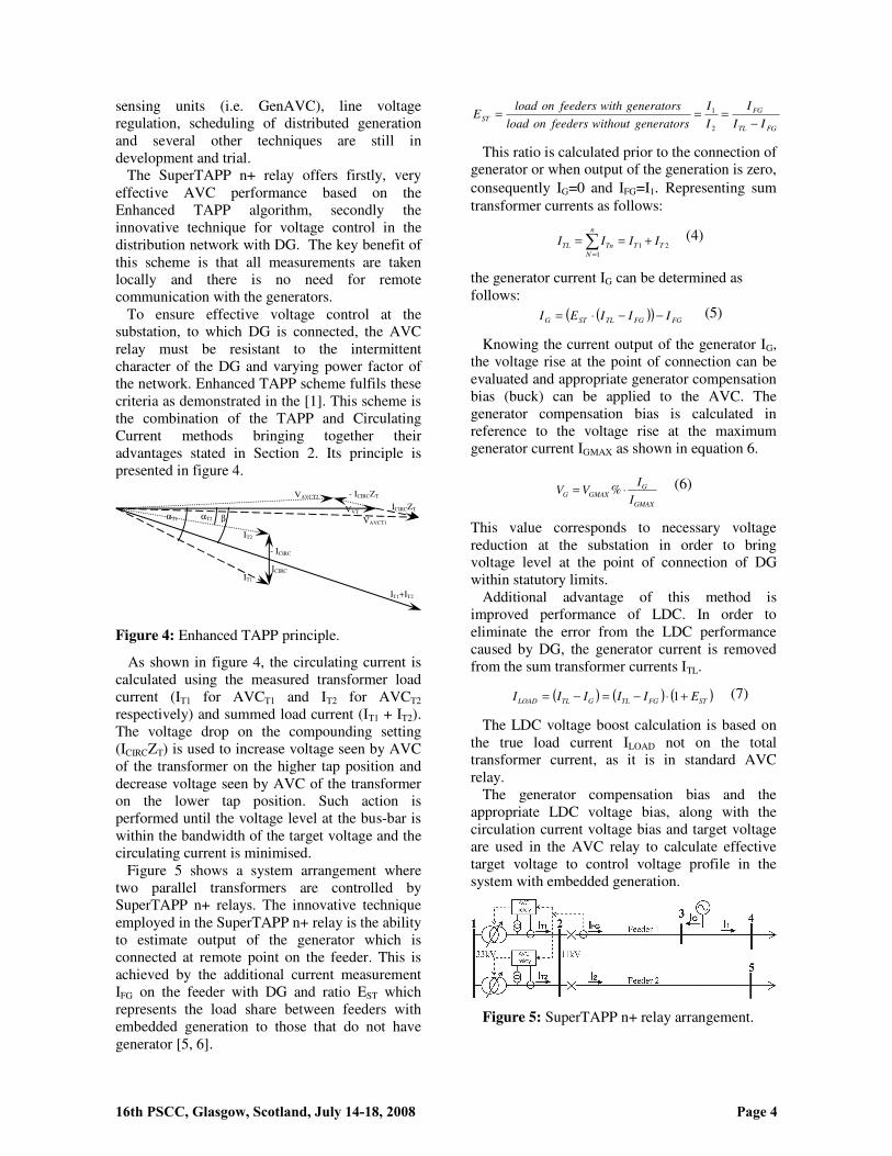
advantages stated in Section 2. Its principle is
presented in figure 4.
Figure 4: Enhanced TAPP principle.
As shown in figure 4, the circulating current is
calculated using the measured transformer load
current (IT1 for AVCT1 and IT2 for AVCT2
respectively) and summed load current (IT1 + IT2).
The voltage drop on the compounding setting
(ICIRCZT) is used to increase voltage seen by AVC
of the transformer on the higher tap position and
decrease voltage seen by AVC of the transformer
on the lower tap position. Such action is
performed until the voltage level at the bus-bar is
within the bandwidth of the target voltage and the
circulating current is minimised.
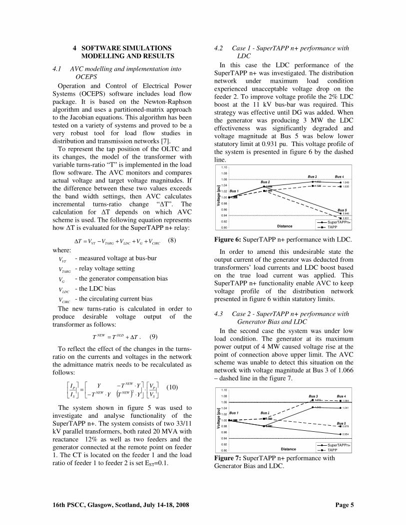
Figure 5 shows a system arrangement where
two parallel transformers are controlled by
SuperTAPP n+ relays. The innovative technique
employed in the SuperTAPP n+ relay is the ability
to estimate output of the generator which is
connected at remote point on the feeder. This is
achieved by the additional current measurement
IFG on the feeder with DG and ratio EST which
represents the load share between feeders with
embedded generation to those that do not have
generator [5, 6].
FGTL
FG
STII
I
I
I
generatorswithoutfeedersonload
generatorswithfeedersonloadE
−===
2
1
This ratio is calculated prior to the connection of
generator or when output of the generation is zero,
consequently IG=0 and IFG=I1. Representing sum
transformer currents as follows:
21
1
TT
n
N
TnTL IIII +== ∑=
(4)
the generator current IG can be determined as
follows:
( )( )FGFGTLSTG IIIEI −−⋅= (5)
Knowing the current output of the generator IG,
the voltage rise at the point of connection can be
evaluated and appropriate generator compensation
bias (buck) can be applied to the AVC. The
generator compensation bias is calculated in
reference to the voltage rise at the maximum
generator current IGMAX as shown in equation 6.
GMAX
GGMAXG
I
IVV ⋅= % (6)
This value corresponds to necessary voltage
reduction at the substation in order to bring
voltage level at the point of connection of DG
within statutory limits.
Additional advantage of this method is
improved performance of LDC. In order to
eliminate the error from the LDC performance
caused by DG, the generator current is removed
from the sum transformer currents ITL.
( ) ( ) ( )STFGTLGTLLOAD EIIIII +⋅−=−= 1 (7)
The LDC voltage boost calculation is based on
the true load current ILOAD not on the total
transformer current, as it is in standard AVC
relay.
The generator compensation bias and the
appropriate LDC voltage bias, along with the
circulation current voltage bias and target voltage
are used in the AVC relay to calculate effective
target voltage to control voltage profile in the
system with embedded generation.
Figure 5: SuperTAPP n+ relay arrangement.
ICIRC
VVT
IT1
β αT1
- ICIRC
αT2
IT2
IT1+IT2
ICIRCZT
VAVCT2
VAVCT1
- ICIRCZT
16th PSCC, Glasgow, Scotland, July 14-18, 2008 Page 4
4 SOFTWARE SIMULATIONS
MODELLING AND RESULTS
4.1 AVC modelling and implementation into
OCEPS
Operation and Control of Electrical Power
Systems (OCEPS) software includes load flow
package. It is based on the Newton-Raphson
algorithm and uses a partitioned-matrix approach
to the Jacobian equations. This algorithm has been
tested on a variety of systems and proved to be a
very robust tool for load flow studies in
distribution and transmission networks [7]. To represent the tap position of the OLTC and
its changes, the model of the transformer with
variable turns-ratio “T” is implemented in the load
flow software. The AVC monitors and compares
actual voltage and target voltage magnitudes. If
the difference between these two values exceeds
the band width settings, then AVC calculates
incremental turns-ratio change “∆T”. The
calculation for ∆T depends on which AVC
scheme is used. The following equation represents
how ∆T is evaluated for the SuperTAPP n+ relay:
CIRCGLDCTARGVT VVVVVT +++−=∆ (8)
where:
VTV - measured voltage at bus-bur
TARGV - relay voltage setting
GV - the generator compensation bias
LDCV - the LDC bias
CIRCV - the circulating current bias
The new turns-ratio is calculated in order to
produce desirable voltage output of the
transformer as follows:
TTT OLDNEW ∆+= . (9)
To reflect the effect of the changes in the turns-
ratio on the currents and voltages in the network
the admittance matrix needs to be recalculated as
follows:
( )
⋅
⋅⋅−
⋅−=
S
P
NEWNEW
NEW
S
P
V
V
YTYT
YTY
I
I2
(10)
The system shown in figure 5 was used to
investigate and analyse functionality of the
SuperTAPP n+. The system consists of two 33/11
kV parallel transformers, both rated 20 MVA with
reactance 12% as well as two feeders and the
generator connected at the remote point on feeder
1. The CT is located on the feeder 1 and the load
ratio of feeder 1 to feeder 2 is set EST=0.1.
4.2 Case 1 - SuperTAPP n+ performance with
LDC
In this case the LDC performance of the
SuperTAPP n+ was investigated. The distribution
network under maximum load condition
experienced unacceptable voltage drop on the
feeder 2. To improve voltage profile the 2% LDC
boost at the 11 kV bus-bar was required. This
strategy was effective until DG was added. When
the generator was producing 3 MW the LDC
effectiveness was significantly degraded and
voltage magnitude at Bus 5 was below lower
statutory limit at 0.931 pu. This voltage profile of
the system is presented in figure 6 by the dashed
line.
1.000
1.036
1.052 1.049
1.000
1.036
0.946
1.000
1.022
1.038 1.035
1.000
1.022
0.931
0.90
0.92
0.94
0.96
0.98
1.00
1.02
1.04
1.06
1.08
1.10
Distance
Vo
ltag
e [
pu
]
SuperTAPPn+
TAPP
Bus 3
Bus 5
Bus 2
Bus 1
Bus 4
Figure 6: SuperTAPP n+ performance with LDC.
In order to amend this undesirable state the
output current of the generator was deducted from
transformers’ load currents and LDC boost based
on the true load current was applied. This
SuperTAPP n+ functionality enable AVC to keep
voltage profile of the distribution network
presented in figure 6 within statutory limits.
4.3 Case 2 - SuperTAPP n+ performance with
Generator Bias and LDC
In the second case the system was under low
load condition. The generator at its maximum
power output of 4 MW caused voltage rise at the
point of connection above upper limit. The AVC
scheme was unable to detect this situation on the
network with voltage magnitude at Bus 3 of 1.066
– dashed line in the figure 7.
1.000
0.980
1.043 1.041
1.000
0.980
0.954
1.0001.005
1.066 1.064
1.0001.005
0.979
0.90
0.92
0.94
0.96
0.98
1.00
1.02
1.04
1.06
1.08
1.10
Distance
Vo
ltag
e [p
u]
SuperTAPPn+
TAPP
Bus 5
Bus 3
Bus 2Bus 1
Bus 4
Figure 7: SuperTAPP n+ performance with
Generator Bias and LDC.
16th PSCC, Glasgow, Scotland, July 14-18, 2008 Page 5

When SuperTAPP n+ was used with the 2%
generator compensation bias setting at the
maximum output of the generator the AVC was
able to reduce voltage level at 11 kV bus-bar in
order to bring voltage at the Bus 3 within the
limit. The performance of this AVC scheme is
presented in figure 7 by the continuous line.
4.4 Study System
Figure 8 shows the one-line diagram of the
132/11 kV local distribution network. The
substation is equipped with two 30 MVA
transformers with OLTCs. These transformers can
apply voltage variations in the range of +/- 10% in
32 steps and are controlled by AVC relay. Five
units of DG with the total rated capacity of 5 MW
are connected to the distribution network. All
units are represented as the one generator
connected at the Bus 3. The generator is requested
to operate at unity power factor. The distribution
network supplies residential and commercial
customers with a load demand of maximum 50
MVA, minimum 15 MVA and overall power
factor of 0.96. Feeder 1 supplies Load 1 and has
the generator connected along its length. Feeder 2
represents the feeder of the network with the
lowest voltage profile. Load 3 relates to the rest of
the load of the substation.
Figure 8: One-line diagram of 132/11kV
distribution network.
Currently the generator is connected to the
distribution network with an overvoltage
protection relay. When the voltage at the point of
connection increases to an unacceptable level, the
generator is requested to reduce its output. The
generator has experienced several tripping due to
high voltage, especially under low load
conditions.
The OCEPS software was used to analyse
SuperTAPP n+ relay functionality in the above
system. Enhanced TAPP algorithm with the
generator output calculation technique was used
to control AVCs of the transformers. An
additional CT was employed on the feeder with
the generator in order to provide current
measurement to the relays. The load ratio of the
feeder with generator to the feeders which do not
have generators was calculated based on the
historical data and set EST=0.18. The LDC was set
to provide 2% boost at the maximum load, and the
generator compensation bias was set at 2% at the
5 MW generator output.
The simulation was performed under various
load and generator output conditions. The results
are presented in figure 9.
Figure 9: Performance of the SuperTAPP n+ in
the distribution network.
The AVCs maintained the voltage profile of the
system within statutory limits at the substation as
well as at the remote points of the feeders. The
voltage magnitude at the point of connection of
the generator at Bus 3 was kept below 1.06 pu
while voltage level along feeder 2 and at Bus 5
was kept above 0.94 pu.
This voltage improvement prevented
undesirable voltage rise at the Bus 3 and helped to
avoid unnecessary tripping of the generator.
5 CONCLUSIONS AND FURTHER WORK
In this paper the functionality of the innovative
AVC scheme was presented. The performance of
the SuperTAPP n+ relay in realistic distribution
network was demonstrated and analyzed. The
study results of this paper confirm that this AVC
technique can be an accurate method of voltage
control at the substation bus-bar as well as at the
remote points of the feeders in the distribution
network with DG. The main advantage of this
scheme is that all measurements are taken locally.
With the accurate LDC settings, the proper
voltage profile of heavily loaded network with
significant penetration of DG can be maintained.
Also with the appropriate settings of the generator
compensation bias the system where DG causes
unacceptable voltage rise at some point of the
feeder can be controlled.
The numerical results presented in this paper
correspond to the specific system however the
load flow software created to perform it can be
used for variety of distribution network cases. The
software can be used as a universal tool for
16th PSCC, Glasgow, Scotland, July 14-18, 2008 Page 6
network planning engineers in order to investigate
opportunities to accommodate additional DG and
for the voltage profile improvements using the
SuperTAPP n+ relay.
It is important to note that as long as one feeder
attached to the substation under consideration
remains without DG then it can be used as a
reference feeder the SuperTAPP n+ scheme. In
such circumstances the scheme can then be
applied generally in order to consider networks
with DG present in several feeders. Further work
will demonstrate the application of the
SuperTAPP n+ scheme in such scenarios based
upon real network models with varying load
conditions.
REFERENCES
[1] M. Fila, G.A Taylor, J. Hiscock, “Systematic
modelling and analysis of TAPP voltage
control schemes”, 42nd
International
Universities Power Engineering Conference,
UPEC 2007, pp. 327-334, Brighton, UK, 4-6
September 2007
[2] M. Thomson, “Automatic-voltage-control
relays and embedded generation”, Power
Engineering Journal, No. 14, pp. 71-76, 2000
[3] V.P. Thorney, N.J. Hiscock, “Improved
voltage quality through advances in voltage
control techniques”, IEE Seventh
International Conference on Developments in
Power System Protection, pp. 355-358, 2001
[4] "Technical Specification for Advanced
Voltage Control Relay - SuperTAPP n+”,
Fundamentals Ltd, 2006
[5] J. N. Hiscock, D. J. Goodfellow, “A Voltage
Control Scheme for High Voltage Power
Transformers”, UK Patent Application GB
2417376, 2004
[6] J. N. Hiscock, D.J. Goodfellow, “Voltage
Control of Electrical Networks with
Embedded Generation”, UK Patent
Application GB 2421596, 2004
[7] M.R.Irving, M.J.H.Sterling, “Efficient
Newton-Raphson algorithm for load flow
solution in transmission and distribution
networks”, Proc IEE, C,134,5,1987, pp325-
328
[8] “Automatic Voltage Control” EI 05-1050,
EDF Energy Networks, 2007
16th PSCC, Glasgow, Scotland, July 14-18, 2008 Page 7


![[The Sun] Tapp: The Real Me](https://img.pdfslide.us/doc/110x75/563db789550346aa9a8bf828/the-sun-tapp-the-real-me.jpg)