Embed Size (px)
Citation preview

8/13/2019 Modelling and Analysis of Squirrel Cage Induction Motor With Leading Reactive Power Injection
http://slidepdf.com/reader/full/modelling-and-analysis-of-squirrel-cage-induction-motor-with-leading-reactive 1/28
Chapter 4
© 2012 Jimoh et al., licensee InTech. This is an open access chapter distributed under the terms of theCreative Commons Attribution License (http://creativecommons.org/licenses/by/3.0), which permitsunrestricted use, distribution, and reproduction in any medium, provided the original work is properly cited.
Modelling and Analysis of Squirrel Cage
Induction Motor with Leading ReactivePower Injection
Adisa A. Jimoh, Pierre-Jac Venter and Edward K. Appiah
Additional information is available at the end of the chapter
http://dx.doi.org/10.5772/50011
1. Introduction
Induction motors are by far the most used electro-mechanical device in industry today.Induction motors hold many advantages over other types of motors. They are cheap,rugged, easily maintainable and can be used in hazardous locations. Despite its advantagesit has one major disadvantage. It draws reactive power from the source to be able to operate
and therefore the power factor of the motor is inherently poor especially under startingconditions and under light load (Jimoh and Nicolae, 2007). Poor power factor adverselyaffects the economics of distribution and transmission systems and therefore may lead tohigher electricity charges (Muljadi et al., 1989). At starting, power drawn by the motor ismainly reactive and it can draw up to 8 times its rated current at a power factor of about 0.2until it reaches rated speed after which the power factor will increase to more than 0.6 if themotor is properly loaded and depending on the size of the motor.
To improve the power factor, reactive power compensation is needed where reactive poweris injected. Several techniques have been suggested including synchronous compensationwhich is complex and expensive. Switched capacitor banks which requires expensiveswitchgear and may cause voltage regeneration, over voltage and high inrush currents (El-Sharkawi et al., 1985).
In this chapter another approach for power factor correction is explored where the stator ofan induction motor has two sets of three phase windings which is electrically isolated butmagnetically coupled. The main winding is connected to the three phase supply and theauxiliary winding connected to fixed capacitors for reactive power injection.
The first part of this chapter focuses on the development of a mathematical model for anormal three phase induction motor, the second part of the chapter focuses on the

8/13/2019 Modelling and Analysis of Squirrel Cage Induction Motor With Leading Reactive Power Injection
http://slidepdf.com/reader/full/modelling-and-analysis-of-squirrel-cage-induction-motor-with-leading-reactive 2/28
Induction Motors – Modelling and Control100
development of the mathematical model for a dual winding three phase induction motorwith reactive power injection, where the derived mathematical model is simulated usingMatlab/Simulink environment and the third part of the chapter focuses on the performanceanalysis of both theoretical and experimental results.
2. Arbitrary reference frame theory
Arbitrary reference frame theory is mainly used in the dynamic analysis of electricalmachines. Because of the highly coupled nature of the machine, especially the inductanceswithin the winding make it rather impossible to perform dynamic simulations and analysison electrical machines.
Arbitrary reference frame theory was discovered by Blondel, Dreyfus, Doherty and Nickleas mentioned in the classical paper (Park, 1929). This newly found theory was generalised
by Park on synchronous machines and this method was later extended by Stanley to theapplication of dynamic analysis of induction machines (Stanley, 1938).
By using this method a poly-phase machine is transformed to a two-phase machine withtheir magnetic axis in quadrature as illustrated in Figure 1. This method is also commonlyreferred to as the dq method in balanced systems and to the dq0 method in unbalancedsystems with the ‘ 0’relating to the zero sequence or homopolar component in the FortescueTransformation.
Figure 1. Park’s Transform
This transformation eliminates mutual magnetic coupling between the phases and thereforemakes the magnetic flux linkage of one winding independent of the current of anotherwinding.
The transformation is done by applying a transformation matrix, Equation (1) while theinverse transformation matrix, Equation (2) will transform back to the natural referenceframe. Equations (1)&(2) applies to a three phase system but can be modified to

8/13/2019 Modelling and Analysis of Squirrel Cage Induction Motor With Leading Reactive Power Injection
http://slidepdf.com/reader/full/modelling-and-analysis-of-squirrel-cage-induction-motor-with-leading-reactive 3/28
Modelling and Analysis of Squirrel Cage Induction Motor with Leading Reactive Power Injection 101
accommodate a system with any number of phases which might be useful in the case of themachine having an auxiliary winding as proposed in this work.
= − − − − (1)
= − − 1 − − 1 (2)
3. Modelling of three-phase induction motor
The winding arrangement of a symmetrical induction machine is shown in Figure 2. Thestator windings are identical and sinusoidally distributed, displaced 120
˚
apart, with N s equivalent turns and resistance r s per winding per phase. Similarly the rotor windings arealso considered as three identical sinusoidally distributed windings, displaced 120
˚
apart,with N r equivalent turns and resistance of r r per winding per phase.
Figure 2. Three-Phase Winding Arrangement
In developing the equations which describe the behaviour of the induction machine thefollowing assumptions are made:
1. The airgap is uniform.2. Eddy currents, friction and windage losses and saturation are neglected.3. The windings are distributed sinusoidally around the air gap.4. The windings are identical

8/13/2019 Modelling and Analysis of Squirrel Cage Induction Motor With Leading Reactive Power Injection
http://slidepdf.com/reader/full/modelling-and-analysis-of-squirrel-cage-induction-motor-with-leading-reactive 4/28
Induction Motors – Modelling and Control102
3.1. Voltage equations
Using Kirchoff’s Voltage Law, the voltage equations for each winding on the stator androtor can be determined.
Stator Windings:
= + (3)
= + (4)
= + (5)
Rotor Windings:
= + (6)
= + (7)
= + (8)
With subscript ‘a’,’b’,’c’ referring to the phases, subscript ‘s’ referring to stator variables,subscript ‘r’ referring to rotor variables, ‘v’ referring to instantaneous voltage, ‘i’ referring toinstantaneous current and ‘ ’ referring to flux linkage.
After obtaining the voltage equations in the natural reference frame, the transformation tothe arbitrary reference frame can be done. It is very convenient to first refer all rotorvariables to the stator by applying the appropriate turns ratio. Equations (9)-(11) representsall rotor variables and is expressed in a simplified way including the variables of all therotor phases in one equation.
′ = (9)
′ = (10)
′ = (11)
The transformation of the voltage equations to the arbitrary reference frame are dealt within Section 3.3. It is important to determine the different inductances which will influence theflux linkage in Equations (3)-(8) and also transform it to the arbitrary reference frame.
3.2. Inductances
The flux linkages as seen in the voltage equations are functions of inductance and thereforethe inductances within the motor must be determined.

8/13/2019 Modelling and Analysis of Squirrel Cage Induction Motor With Leading Reactive Power Injection
http://slidepdf.com/reader/full/modelling-and-analysis-of-squirrel-cage-induction-motor-with-leading-reactive 5/28

8/13/2019 Modelling and Analysis of Squirrel Cage Induction Motor With Leading Reactive Power Injection
http://slidepdf.com/reader/full/modelling-and-analysis-of-squirrel-cage-induction-motor-with-leading-reactive 6/28
Induction Motors – Modelling and Control104
Stator-stator mutual inductance can be expressed as Equation (17) (Lipo and Novotny,1996).
= ℓ (17)
Where L xsys is the inductance between any stator winding ‘ x’ and any other stator winding‘ y’ and is the angle between stator winding ‘ x’ and ‘ y’.
Using Equation (14), Equation (17) can be modified to be:
= (18)
When considering the winding distribution in Figure 2, it can be seen that the only possibledisplacement between two stator windings are 120
˚
and 240˚
in both directions. This impliesthat in Equation (18) can be evaluated as follows:
= cos ±120° = cos ±240° = − (19)
From Equations (18)&(19) the expression describing the mutual inductance between anytwo stator windings can be simplified to Equation (20).
= = = = = = − (20)
The rotor-rotor mutual inductances are similar to that of the stator-stator mutualinductances and can be expressed as:
= = = = = = − (21)
The stator-rotor mutual inductances depend on the position of the rotor according to thefollowing relationship.
= (22)
Where is the mutual inductance between any stator winding ‘ x’ and any rotor winding‘ y’; and is the angle between them.
The expression for in Equation (22) is given by Equation (23).
= ℓ (23)
(Krause, 1986, Lipo and Novotny, 1996)
Now, using Equation (22) and Figure 2, the expressions for the stator-rotor mutualinductances can be deduced.
= = = (24)
= = = + (25)

8/13/2019 Modelling and Analysis of Squirrel Cage Induction Motor With Leading Reactive Power Injection
http://slidepdf.com/reader/full/modelling-and-analysis-of-squirrel-cage-induction-motor-with-leading-reactive 7/28
Modelling and Analysis of Squirrel Cage Induction Motor with Leading Reactive Power Injection 105
= = = − (26)
Likewise it can be shown that the rotor-stator mutual inductances are:
= = = cos(−) (27)
= = = − (28)
= = = − (29)
All inductances have now been quantified. The complete inductance matrix can now beconstructed but to simplify the work the inductance matrix in Equation (12) is first dividedinto sub-matrices. The inductance matrix as in Equation (12) is repeated as Equation (30).
= (30)
The inductance matrix is divided into four sub-matrices.
= (31)
Where is the inductance within the stator windings, is the inductances within the rotorwindings, is the inductances between stator and rotor windings and is theinductances between the rotor and stator windings.
Using Equation (30) and dividing according to Equation (31) and substituting inductancesyield the following:
= + − −− + −− − +
(32)
= + − −− + −− − + (33)
= cos( + ) cos( − )cos( − ) cos( + )cos( +
) cos( −
)
(34)

8/13/2019 Modelling and Analysis of Squirrel Cage Induction Motor With Leading Reactive Power Injection
http://slidepdf.com/reader/full/modelling-and-analysis-of-squirrel-cage-induction-motor-with-leading-reactive 8/28
Induction Motors – Modelling and Control106
() = cos( − ) cos( + )cos( + ) cos( − )cos( −
) cos( +
)
(35)
It can be proven that ( ).
It is evident that exists in Equations (34)&(35) where relates to rotor position, this rotorposition changes continuously which means that in the natural state the inductances arevarying with time. To be able to derive a rigorous dynamic model de-coupling has to bedone by using arbitrary reference frame theory as mentioned in Section 2.
Before transforming the inductances to the arbitrary reference frame all rotor parametersmust be referred to the stator.
The magnetizing inductances (
, ) and mutual inductances (
, ) are from the
same magnetic flux path and are therefore related. From Equations (14)&(23) it can bededuced that:
= (36)
By using the effective turns ratio can be referred to the stator.
′ = () (37)
And therefore
′ = (38)The mutual inductance matrix referred to the stator can now be expressed as:
′ = cos( + ) cos( − )cos( − ) cos( + )cos( + ) cos( − ) (39)
Using the same approach the inductances within the rotor windings can also be simplified as:
′ = ′ + − −− ′ + −− − ′ + (40)
The flux linkage can now be expressed as:
′ = ′( ′) ′ × ′ (41)
Equation (41) can be transformed to the arbitrary reference frame as indicated in Equation(42) (Krause, 1986).

8/13/2019 Modelling and Analysis of Squirrel Cage Induction Motor With Leading Reactive Power Injection
http://slidepdf.com/reader/full/modelling-and-analysis-of-squirrel-cage-induction-motor-with-leading-reactive 9/28
Modelling and Analysis of Squirrel Cage Induction Motor with Leading Reactive Power Injection 107
′ = ′( ′) ′ × ′ (42)
Where;
= − − − − (43)
= − − 1 − − 1 (44)
= − − − − (45)
= 1 − − 1 − − 1 (46)
Where;
= − (47)
is the transformation matrix and the inverse transformation matrix for the statorparameters, is the transformation matrix and the inverse transformation matrix forthe rotor parameters.
Evaluating Equation (42) with Equations (43)-(46) yield the flux linkage in the arbitraryreference frame as shown in Equation (48).
Comparing Equation (48) with Equations (32)-(35), it is clear that has been eliminatedfrom the flux linkage equations by using the arbitrary reference frame transformation. Itmeans that the flux linkage is no longer a function of rotor position.
′′′=
+ 0 0 0 00 + 0 0 00 0 0 0 0 0 0 ′ + 0 00 0 0 ′ + 00 0 0 0 0
× ′′′ (48)

8/13/2019 Modelling and Analysis of Squirrel Cage Induction Motor With Leading Reactive Power Injection
http://slidepdf.com/reader/full/modelling-and-analysis-of-squirrel-cage-induction-motor-with-leading-reactive 10/28
Induction Motors – Modelling and Control108
= (49)
3.3. Voltage equations in arbitrary reference frame
Recalling and repeating the voltage equations in the natural reference frame in section 3.1,for ease of reading only, now it is presented in matrix format.
= + (50)
′ = ′′ + (51)
Taking only the stator voltage equations as in Equation (50) and only considering theresistive part, it can be transformed to the arbitrary reference frame as follows:
= (52)
= 0 00 00 0 (53)
Therefore;
= (54)
Where;
= 0 00 00 0 (55)
The superscript ‘ res’ refers to the resistive part of the voltage equation.
Now considering only the inductive part of the of the voltage equation as in Equation (50)which can be transformed to the arbitrary reference frame as follows:
= (56)
Expanding Equation (56) using the product rule:
= + (57)
Now, evaluating parts of the terms in Equation (57) separately;
Knowing that;
= () + (0) (58)

8/13/2019 Modelling and Analysis of Squirrel Cage Induction Motor With Leading Reactive Power Injection
http://slidepdf.com/reader/full/modelling-and-analysis-of-squirrel-cage-induction-motor-with-leading-reactive 11/28
Modelling and Analysis of Squirrel Cage Induction Motor with Leading Reactive Power Injection 109
Where is a dummy variable for integration.
= − − − −
0− + + 0
(59)
= 0 0− 0 00 0 0 (60)
= 1 0 00 1 00 0 1 (61)
Using Equations (58)-(61) to evaluate Equation (57) yields;
= −0 + (62)
The superscript ‘ ind’ refers to the inductive part of the voltage equation.
Now adding the voltage equations for the resistive and inductive parts gives the full statorvoltage equations in the arbitrary reference frame.
= 0 00 00 0 + −0 + (63)
Using the same method the rotor voltage equation can be determined.
′ = ′ 0 00 ′ 00 0 ′′′′ + ( − ) ′− ′0 + ′′ (64)
Where is the rotational speed of the reference frame and is the rotational speed of therotor.
The model developed up to now is a general model in the arbitrary reference frame whichmeans that this model can take the form of any reference frame depending the valuesubstituted for , therefore called arbitrary.
Different reference frames are obtained by substituting the appropriate value of thereference frame speed into . Three different reference frames are commonly used, thestationary reference frame where = 0 , the synchronous reference frame where is set tothe angular velocity of the supply voltage ( = ) and the rotor reference frame where isset to the angular velocity of the rotor ( = ). The use of reference frames depends on thenature of the problem to be solved.

8/13/2019 Modelling and Analysis of Squirrel Cage Induction Motor With Leading Reactive Power Injection
http://slidepdf.com/reader/full/modelling-and-analysis-of-squirrel-cage-induction-motor-with-leading-reactive 12/28
Induction Motors – Modelling and Control110
3.4. Electromagnetic torque
The torque equation for a three phase induction machine is well known and is not derivedin this section. The torque equation of the three phase machine with auxiliary winding is
derived in Section 4.
= − (65)
An electric motor is an electro-mechanical device and needs an equation that couples theelectrical and mechanical systems.
= + (66)
Where P is number of poles, J is moment of inertia, T L is torque connected to the shaft and is the angular rotational speed of the rotor.
3.5. Equivalent circuit
The full mathematical model of the three phase induction machine is given by Equations(48),(63)&(64). These equations are used to develop the equivalent circuits for the threephase induction machine as in Figure 3
Figure 3. Equivalent Circuits
4. Modelling of three-phase with auxiliary winding
This machine consists of two three phase windings arranged on top of each other in thesame slots. This means that there is no displacement between the two windings. These twowindings are electrically isolated but magnetically connected. One of these windings istreated as the main winding and will be supplied with a three phase voltage. The main

8/13/2019 Modelling and Analysis of Squirrel Cage Induction Motor With Leading Reactive Power Injection
http://slidepdf.com/reader/full/modelling-and-analysis-of-squirrel-cage-induction-motor-with-leading-reactive 13/28
Modelling and Analysis of Squirrel Cage Induction Motor with Leading Reactive Power Injection 111
winding is labelled with the subscript ‘ abc’. The remaining winding is treated as theauxiliary winding. The auxiliary winding is connected to static capacitors for reactive powerinjection. The injection of reactive power will improve the power factor of the machine. Theauxiliary winding is labelled with the subscript ‘ xyz’. The winding arrangement is as shownin Figure 4.
Figure 4. Winding arrangement of Main and Auxiliary Windings
The assumptions in developing the equations which describe the behaviour of this machineare the same as the assumptions mentioned in Section 3 with one addition. It is assumedthat the main and auxiliary winding is identical. It has the same conductor cross section andthe same number of turns.
4.1. Voltage equations
The voltage equations for this machine are developed in the same way as described inSection 3.1. There are three additional voltage equations because of the additional set ofthree phase windings. For simplicity the voltage equations are represented in matrix format.It is assumed that the main and auxiliary windings are identical and will therefore have thesame resistance.
Main Stator Windings:
= + (67)
Auxiliary Stator Windings:
= + (68)
Rotor Windings:
′ = ′′ + (69)
4.2. Inductances
Because of the addition of the auxiliary winding the dimensions of the inductance matrixwill increase. The dimension of the inductance matrix is equal to the number of windings, in

8/13/2019 Modelling and Analysis of Squirrel Cage Induction Motor With Leading Reactive Power Injection
http://slidepdf.com/reader/full/modelling-and-analysis-of-squirrel-cage-induction-motor-with-leading-reactive 14/28
Induction Motors – Modelling and Control112
this case a [9 x 9] matrix. The inductance matrix can again be divided into smaller moremanageable sub-matrices as in Equation (70).
___ = (70)
where L abcs , Lxyzs , Labcr are the inductances within the different three phase sets of windings.The other sub-matrices refer to mutual inductances between different sets of windings. Thisincludes stator and rotor windings, for example L abcsxyzs refer to the mutual inductance between the main winding and the auxiliary winding on the stator. Many of the inductancesin this structure are very similar to that of the conventional three phase machine. Therefore,many of the developed inductances in Section 3 can be used.
= = + − −− + −− − + (71)
= + − −− + −− − + (72)
= = cos( + ) cos( −
)cos( − ) cos( + )cos( + ) cos( − )
(73)
= = (74)
All of the above was taken from Section 3 because of similar relationships between thewindings. The only sub-matrices remaining are the two describing the inductances betweenthe main and auxiliary windings on the stator. For determining the expressions of all theelements of the sub-matrices, equation (18) is used.
= (75)
Where;
= = = cos 0° = (76)
= = = = = = cos ±120° = − (77)
Now;

8/13/2019 Modelling and Analysis of Squirrel Cage Induction Motor With Leading Reactive Power Injection
http://slidepdf.com/reader/full/modelling-and-analysis-of-squirrel-cage-induction-motor-with-leading-reactive 15/28
Modelling and Analysis of Squirrel Cage Induction Motor with Leading Reactive Power Injection 113
= − −− −− −
(78)
It can be shown that;
= (79)
Mutual leakage inductance exists between the main and auxiliary windings because they aresharing the same stator slots. This mutual leakage inductance should be reflected inEquation (78) but are neglected for the purpose of this study.
Transforming the inductance matrix in the natural reference frame to the arbitrary referenceframe as explained in Section 3.2 yields the following inductance matrix in the arbitrary
reference frame.
= 0 0 0 0 0 00 0 0 0 0 00 0 0 0 0 0 0 0 0 0 0 0 0 00 0 0 0 0 00 0 0 0 0 0 0 0 0 0 0 0 0 00 0 0 0 0 0
0 0 0 0 0 0 0 0
(80)
Where;
= + (81)
= ′ + (82)
Where the subscripts ‘ 1’ refers to the main stator winding, ‘2’ refers to the auxiliary statorwinding and ‘r’ refers to the rotor winding.
Because flux linkage appears in the voltage equations it is very convenient to represent fluxlinkage instead of inductance.
= (83)
Where Equation (83) is in matrix format and refers to any flux linkage in the system.
4.3. Voltage equation in the arbitrary reference frame
The voltage equations as developed in Section 4.1 can be transformed to the arbitraryreference frame. This is quite an easy task when the developments in Section 3 are used. Theequation for the main winding on the stator and the rotor winding remains the same as thatfor the conventional three-phase machine as shown in Equations (84)-(85).

8/13/2019 Modelling and Analysis of Squirrel Cage Induction Motor With Leading Reactive Power Injection
http://slidepdf.com/reader/full/modelling-and-analysis-of-squirrel-cage-induction-motor-with-leading-reactive 16/28
Induction Motors – Modelling and Control114
= 0 00 00 0 + −0 + (84)
′ = ′ 0 00 ′ 00 0 ′′′′ + ( − ) ′− ′0 + ′′ (85)
The voltage equations of the auxiliary winding are different from the main winding becauseno voltage is applied directly to the winding. Capacitors are rather connected to theauxiliary winding as in Figure 4. It is therefore important to develop the voltage equationfor a capacitor in the arbitrary reference frame. This is given in Equation (86).
=
+ −0
(86)
Now, the voltage equation for the auxiliary winding becomes;
= 0 = 0 00 00 0 + −0 + + 0 (87)
4.4. Electromagnetic torque
The electromagnetic torque can be derived from the energy stored in the coupling system.
The stored energy for a normal three-phase can be written as Equation (88) (Krause, 1986). = ( )( − ) + () ′ ′ + ( ′)( ′ − ′) ′ (88)
Where I is the identity matrix. The machine is assumed to be magnetically linear andtherefore, the field energy is equal to the co-energy .
The change in mechanical energy in a rotational system delivering mechanical power isgiven as:
= (89)
Where T em is electromagnetic torque and is the actual angular displacement of the rotor.The flux linkages, currents, and are all expressed as a function of the electricalangular displacement .
= (90)
Substituting Equation (90) into Equation (89) yields:
= (91)
Because = the electromagnetic torque can be evaluated with:
8/13/2019 Modelling and Analysis of Squirrel Cage Induction Motor With Leading Reactive Power Injection
http://slidepdf.com/reader/full/modelling-and-analysis-of-squirrel-cage-induction-motor-with-leading-reactive 17/28
Modelling and Analysis of Squirrel Cage Induction Motor with Leading Reactive Power Injection 115
, = , (92)
Substituting Equation (88) into Equation (92) gives the electromagnetic torque of the stator side as
(93)
Where,
= (94)
= (95)
= ( − ) (96)
Substituting Equation (95) into Equation (93) gives the torque for each of the stator currents.
= ( )
+( ) + + + (97)
Applying the transformation from ‘ abc’ to ‘dq0’ yields the torque equation:
= − + − (98)
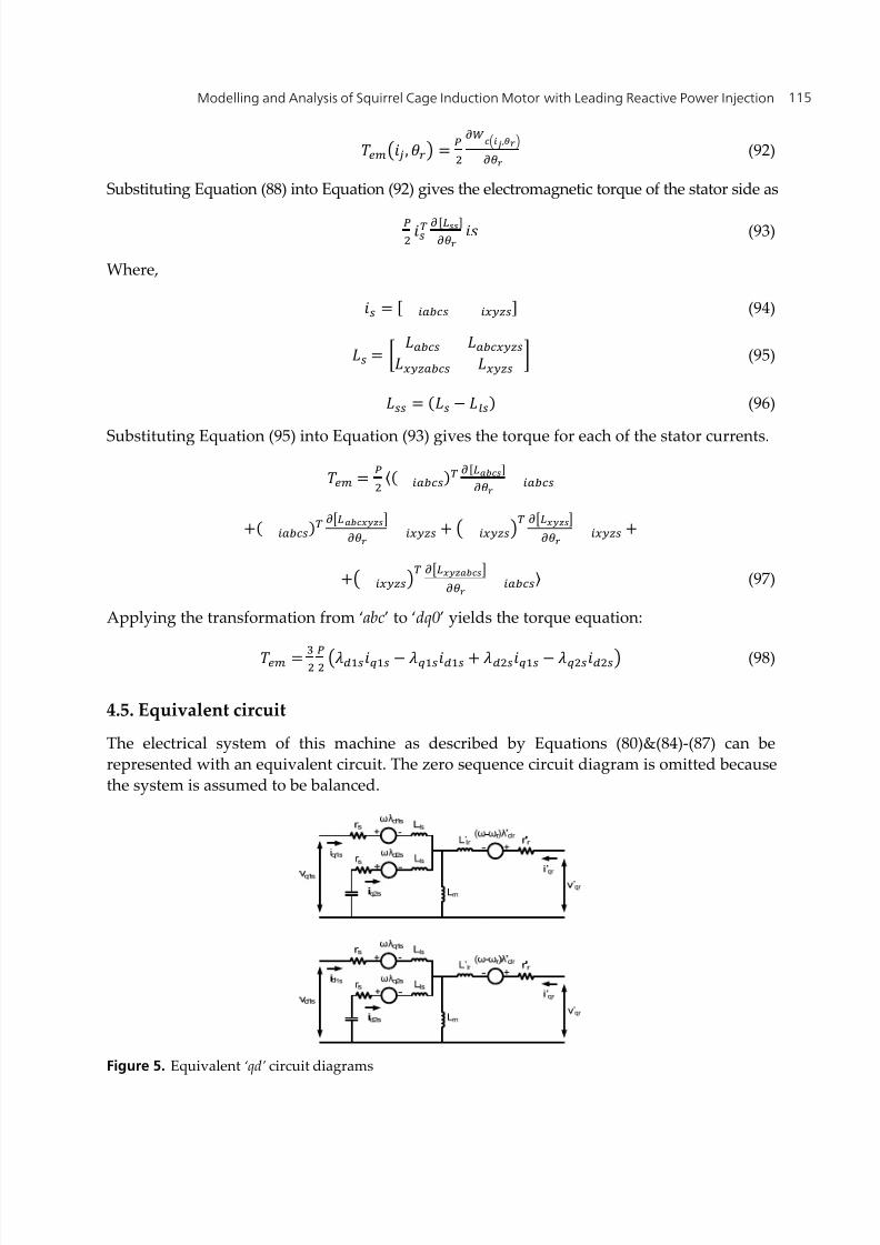
4.5. Equivalent circuit
The electrical system of this machine as described by Equations (80)&(84)-(87) can berepresented with an equivalent circuit. The zero sequence circuit diagram is omitted becausethe system is assumed to be balanced.
Figure 5. Equivalent ‘qd’ circuit diagrams

8/13/2019 Modelling and Analysis of Squirrel Cage Induction Motor With Leading Reactive Power Injection
http://slidepdf.com/reader/full/modelling-and-analysis-of-squirrel-cage-induction-motor-with-leading-reactive 18/28
Induction Motors – Modelling and Control116
5. Simulation results
The derived mathematical models implemented in the Matlab/Simulink environment can beused to generate steady-state and dynamic simulation results. The machine withoutcompensation is used as reference. Capacitance is added to the auxiliary winding andcompared with the behaviour of the reference machine. This will show the effect of thecapacitors connected to the auxiliary winding on the performance of the modified machine.The dynamic model can be used for steady state analysis by taking readings after thetransient.
5.1. Steady state analysis
The main objective of the modifications done in terms of the addition of the auxiliarywinding is to improve the poor power factor an induction motor has. It is therefore
important to focus on the behaviour of the machine parameters that involves power factorwhen introducing reactive power injection.
Figure 6 shows that the injection of reactive power in the auxiliary winding improves thepower factor of the motor. The bigger the size of the capacitor, the more reactive power isinjected and hence the better the power factor. For this specific machine, capacitors of 30µFconnected per phase as in Figure 4 leads to a power factor very close to unity.
Figure 6. Torque – Power Factor waveform
0 0.2 0.4 0.6 0.8 1 1.2 1.40
0.1
0.2
0.3
0.4
0.5
0.6
0.7
0.8
0.9
1
Load Torque (pu)
P o w
e r F a c t o r
Uncompensated10 microF20 microF30 microF

8/13/2019 Modelling and Analysis of Squirrel Cage Induction Motor With Leading Reactive Power Injection
http://slidepdf.com/reader/full/modelling-and-analysis-of-squirrel-cage-induction-motor-with-leading-reactive 19/28
Modelling and Analysis of Squirrel Cage Induction Motor with Leading Reactive Power Injection 117
Figure 7. Torque – Reactive Power waveform
With the increase in power factor as seen in Figure 6 it is expected that less reactive powerwill be drawn from the source with the addition of capacitors to the auxiliary winding.Figure 7 supports this expectation. In Figure 7 the reactive power drawn from the sourcereduces with increasing capacitor size.
Because the reactive component of the supply current decreases with the reactive powerinjection, the magnitude of the supply current therefore decreases. This is shown in Figure 8.
Figure 8. Torque–Current waveform
0 0.2 0.4 0.6 0.8 1 1.2 1.40
0.2
0.4
0.6
0.8
1
1.2
1.4
Load Torque (pu)
R e a c t i v e P o w
e r D r a w
n ( p u
)
Uncompensated10 microF20 microF
30 microF
0 0.2 0.4 0.6 0.8 1 1.2 1.40
0.2
0.4
0.6
0.8
1
1.2
1.4
Load Torque (pu)
C u
r r e
n t ( p u
)
Uncompensated10 microF20 microF30 microF

8/13/2019 Modelling and Analysis of Squirrel Cage Induction Motor With Leading Reactive Power Injection
http://slidepdf.com/reader/full/modelling-and-analysis-of-squirrel-cage-induction-motor-with-leading-reactive 20/28
Induction Motors – Modelling and Control118
Figure 9. Torque Efficiency waveform
The active power drawn from the source consists of different components of which one iscopper losses (I 2R losses). With the decrease of current shown in Figure 8, it is logical thatthe copper losses of the main stator winding will also decrease. This will lead to a decreasein active power drawn from the source without a change in output power and hence theimprovement in the efficiency of the motor as seen in Figure 9.
Figure 10. Capacitance-Power Factor waveform
0 0.2 0.4 0.6 0.8 1 1.2 1.40
0.1
0.2
0.3
0.4
0.5
0.6
0.7
0.8
0.9
1
Load Torque (pu)
E f f i c i e n c y
Uncompensated10 microF20 microF30 microF
0 5 10 15 20 25 30 35 40 450.7
0.75
0.8
0.85
0.9
0.95
1
Capacitance (micro F)
P o w e r
F a c
t o r
8/13/2019 Modelling and Analysis of Squirrel Cage Induction Motor With Leading Reactive Power Injection
http://slidepdf.com/reader/full/modelling-and-analysis-of-squirrel-cage-induction-motor-with-leading-reactive 21/28
Modelling and Analysis of Squirrel Cage Induction Motor with Leading Reactive Power Injection 119
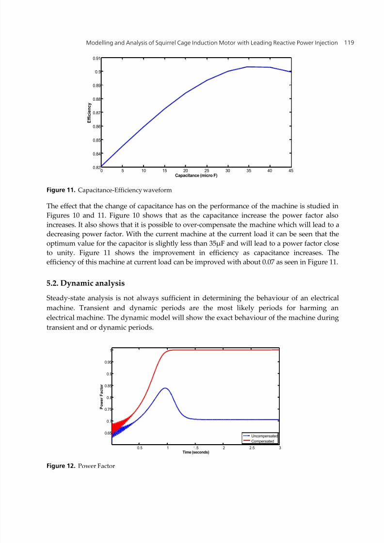
Figure 11. Capacitance-Efficiency waveform
The effect that the change of capacitance has on the performance of the machine is studied inFigures 10 and 11. Figure 10 shows that as the capacitance increase the power factor alsoincreases. It also shows that it is possible to over-compensate the machine which will lead to adecreasing power factor. With the current machine at the current load it can be seen that theoptimum value for the capacitor is slightly less than 35µF and will lead to a power factor closeto unity. Figure 11 shows the improvement in efficiency as capacitance increases. Theefficiency of this machine at current load can be improved with about 0.07 as seen in Figure 11.
5.2. Dynamic analysisSteady-state analysis is not always sufficient in determining the behaviour of an electricalmachine. Transient and dynamic periods are the most likely periods for harming anelectrical machine. The dynamic model will show the exact behaviour of the machine duringtransient and or dynamic periods.
Figure 12. Power Factor
0 5 10 15 20 25 30 35 40 450.83
0.84
0.85
0.86
0.87
0.88
0.89
0.9
0.91
Capacitance (micro F)
E f f i c i e n c y
0.5 1 1.5 2 2.5 3
0.65
0.7
0.75
0.8
0.85
0.9
0.95
1
Time (seconds)
P o w e r
F a c
t o r
UncompensatedCompensated

8/13/2019 Modelling and Analysis of Squirrel Cage Induction Motor With Leading Reactive Power Injection
http://slidepdf.com/reader/full/modelling-and-analysis-of-squirrel-cage-induction-motor-with-leading-reactive 22/28
Induction Motors – Modelling and Control120
Figure 13. Efficiency
The dynamic behaviour of a compensated and uncompensated induction machine iscompared in Figure 12. The uncompensated machine (dashed waveform) has a low powerfactor when starting and settles at a power factor of just more than 0.7. The compensatedmachine (solid waveform) has a higher power factor when starting and settles at a powerfactor close to unity. This shows how effective this concept is in power factor correction.
The earlier statement that the improvement in power factor will improve the efficiency issupported in Figure 13.
The inrush current of the machine is shown in Figure 14. This machine has a transient statewhen starting where the current can reach eight times rated current.
The current of the auxiliary winding is shown in Figure 15.
Figure 14. Phase Currents – Main Stator Winding
0 0.5 1 1.5 2 2.5 3-0.2
0
0.2
0.4
0.6
0.8
1
Time (seconds)
E f f i c i e n c y
UncompensatedCompensated
0 0.5 1 1.5-10
0
10Ia
0 0.5 1 1.5-10
0
10
C u r r e n
t ( p u
)
Ib
0 0.5 1 1.5-10
0
10
Time (Seconds)
Ic

8/13/2019 Modelling and Analysis of Squirrel Cage Induction Motor With Leading Reactive Power Injection
http://slidepdf.com/reader/full/modelling-and-analysis-of-squirrel-cage-induction-motor-with-leading-reactive 23/28
Modelling and Analysis of Squirrel Cage Induction Motor with Leading Reactive Power Injection 121
Figure 15. Phase Currents – Auxiliary Stator Winding
6. Experimental validation
In order to validate the theoretical model with the practical model, three capacitor values of10, 20 and 30µF are used for the three phase auxiliary winding.
Figure 16. The Experimental set up
0 0.2 0.4 0.6 0.8 1 1.2 1.4 1.6 1.8 2-2
0
2Ix
0 0.2 0.4 0.6 0.8 1 1.2 1.4 1.6 1.8 2-2
0
2
C u r r e n
t ( p u
)Iy
0 0.2 0.4 0.6 0.8 1 1.2 1.4 1.6 1.8 2-2
0
2
Time (seconds)
Iz
8/13/2019 Modelling and Analysis of Squirrel Cage Induction Motor With Leading Reactive Power Injection
http://slidepdf.com/reader/full/modelling-and-analysis-of-squirrel-cage-induction-motor-with-leading-reactive 24/28
Induction Motors – Modelling and Control122
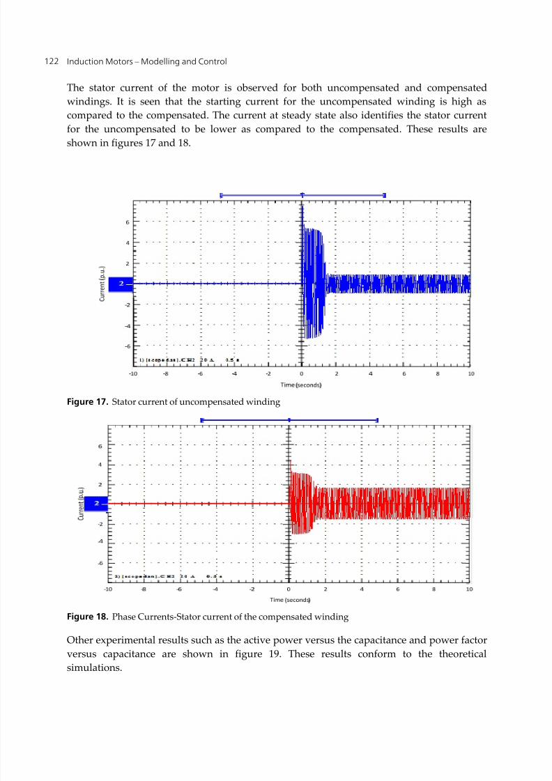
The stator current of the motor is observed for both uncompensated and compensatedwindings. It is seen that the starting current for the uncompensated winding is high ascompared to the compensated. The current at steady state also identifies the stator currentfor the uncompensated to be lower as compared to the compensated. These results areshown in figures 17 and 18.
Figure 17. Stator current of uncompensated winding
Figure 18. Phase Currents-Stator current of the compensated winding
Other experimental results such as the active power versus the capacitance and power factorversus capacitance are shown in figure 19. These results conform to the theoreticalsimulations.

8/13/2019 Modelling and Analysis of Squirrel Cage Induction Motor With Leading Reactive Power Injection
http://slidepdf.com/reader/full/modelling-and-analysis-of-squirrel-cage-induction-motor-with-leading-reactive 25/28
Modelling and Analysis of Squirrel Cage Induction Motor with Leading Reactive Power Injection 123
Figure 19. Experimental results of active power and power factor versus capacitance values
Figure 20. Experimental results of power factor and active power versus firing angle
1.2
1.1
1.0
0 9 18 27 36 45
A c t i v e
P o w e r
( p u
)
*
*
*
*
Capacitance (Micro F)
1.
0.9
0.8
0.70
0.60
0 9 18 27 36 45
P o w e r
f a c t o r
*
*
*
*
*
** *
*
Capacitance (Micro F)
Firing angle ( 0)
0.8
0.
0.7
0.7
0.6
0.6
0 36 72 108 144 180
*
*
*
**
*
* * *
*
P o w e r
f a c t o r
A c t i v e
o w e r
( u
)
*
*
*
*
**
*
*
**
Firin an le (0)

8/13/2019 Modelling and Analysis of Squirrel Cage Induction Motor With Leading Reactive Power Injection
http://slidepdf.com/reader/full/modelling-and-analysis-of-squirrel-cage-induction-motor-with-leading-reactive 26/28
8/13/2019 Modelling and Analysis of Squirrel Cage Induction Motor With Leading Reactive Power Injection
http://slidepdf.com/reader/full/modelling-and-analysis-of-squirrel-cage-induction-motor-with-leading-reactive 27/28
Modelling and Analysis of Squirrel Cage Induction Motor with Leading Reactive Power Injection 125
with experimental set up has shown a great improvement compared to the uncompensatedmachine. Another very important improvement is the supply current decreasing withincreasing capacitance. This is not the case with conventional power factor correction
techniques because the reactive power needed is still drawn through the only stator windingset. This advantage of the modified machine may potentially reduce installation costs assmaller supply cables can be used.
Despite its good performance it has certain drawbacks. The machine would be bigger instructure than a conventional machine. More copper is needed for the additionalwinding and more insulating material is needed. This would make the machine muchmore expensive than the conventional three phase machine. Another drawback of thisconcept is that the capacitors have to be sized for a specific load. When there is anapplication with varying load, the machine might not always operate at optimum power
factor. A possible solution to this is to implement a PWM controller between thecapacitors and the auxiliary winding; this will make the capacitance and therefore powerfactor controllable.
This modified induction machine has a research potential with the recent focus on energyefficiency. Further research needs to be carried out on the performance behaviour of thismachine.
Author details
Adisa A. Jimoh, Pierre-Jac Venter and Edward K. AppiahTshwane University of Technology, Pretoria, South Africa
8. References
el-Sharkawi, M. A., Venkata, S. S., Williams, T. J. & Butler, N. G. (1985) An Adaptive PowerFactor Controller for Three-Phase Induction Generators. Power Apparatus and Systems,IEEE Transactions on, PAS-104 , 1825-1831.
Jimoh, A. A. & Nicolae, D. V. (2007) Controlled Capacitance Injection into a Three-PhaseInduction Motor through a Single-Phase Auxiliary Stator Winding. Electric Machines &
Drives Conference, 2007. IEMDC '07. IEEE International.Krause, P. C. (1986) Analysis of Electric Machinery, New York, Mcgraw-Hill.Lipo, T. A. & Novotny, D. W. (1996) Vector Control and Dynamics of AC Drives. In
Hammond, P., Miller, T. J. E. & Kenjo, T. (Eds.). New York, Oxford Science Publications.Muljadi, E., Lipo, T. A. & Novotny, D. W. (1989) Power factor enhancement of induction
machines by means of solid-state excitation. Power Electronics, IEEE Transactions on, 4, 409-418.
Park, R. H. (1929) Two-Reaction Theory of Synchronous Machines Generalized Method ofAnalysis-Part I. American Institute of Electrical Engineers, Transactions of the, 48, 716-727.

8/13/2019 Modelling and Analysis of Squirrel Cage Induction Motor With Leading Reactive Power Injection
http://slidepdf.com/reader/full/modelling-and-analysis-of-squirrel-cage-induction-motor-with-leading-reactive 28/28
Induction Motors – Modelling and Control126
Stanley, H. C. (1938) An Analysis of the Induction Machine. American Institute of ElectricalEngineers, Transactions of the, 57, 751-7.


![Squirrel-Cage Rotor Options for AC Induction Motors[1]](https://img.pdfslide.us/doc/110x75/553c93a84a7959727a8b49ab/squirrel-cage-rotor-options-for-ac-induction-motors1.jpg)