Embed Size (px)
Citation preview

HCTL Open International Journal of Technology Innovations and Research (IJTIR) http://ijtir.hctl.org Volume 16, July 2015 e-ISSN: 2321-1814, ISBN (Print): 978-1-943730-43-8
Vaishali K. Kumbhale; V. H. Bankar, Modelling and Analysis for Long Roller to be used in Pulp Dewatering Machine.
Page 1
Modelling and Analysis for Long Roller to be used in Pulp Dewatering Machine
Vaishali K. Kumbhale1, V. H. Bankar2
[email protected], [email protected]
Abstract Press role design in bigger size is generally easiest way to developed by sheet metal here we have taken few weldments to make product reliable with the concept of press role machine. The project gives brief idea about and development of new anti bending role design without mid support to withstand with press boundary conditions in heavy duty purpose machine. Roll structure is designed with vertical fins weldments surrounded on cylindrical tube and its wrapped by purported sheet it fulfill the function with squeezing process of soft pulp. Shaft is also the part of roll structure make easy to mount it on machine assembly.
Keywords – Introduction, Designed roll to be used here mechanism, Design of components, Machine view, Tabulated results.
Introduction This work is to be carried out for pulping and Paper industries. Paper industries are full scope supplier of pulping, papermaking and power generation technologies for the pulp and paper industry. Paper industries also part of the fiber business line. The aim of this project is to develop, and evaluate a concept for a new pulp feeding system to one pulping processing machineries. This new system shall enable feeding with a higher pulp consistency, and will wash the dirty pulp compared to existing pulp feed systems. A pre-study is conducted to get acquainted with, and understand the problem. This study can be resulted in a number of goals and demands. After the pre-study concepts generated, and evaluated, one was selected to continue working with. The selected concept will further evaluated through personnel visit to the chemical /mechanical pulping industries. And the potential will be find out from the result.
1, 2 Department of Mechanical Engineering, VIT College of Engineering and Technology, Nagpur, MH, India.

HCTL Open International Journal of Technology Innovations and Research (IJTIR) http://ijtir.hctl.org Volume 16, July 2015 e-ISSN: 2321-1814, ISBN (Print): 978-1-943730-43-8
Vaishali K. Kumbhale; V. H. Bankar, Modelling and Analysis for Long Roller to be used in Pulp Dewatering Machine.
Page 2
Fig.1 Designed roll to be used here mechanism
Fig.2 Tentative conceptual structure view
• As the rotating roll is designed by sheet metal a hollow Cylinder form by sheet metal as shown.
Fig.3 Design of components
HCTL Open International Journal of Technology Innovations and Research (IJTIR) http://ijtir.hctl.org Volume 16, July 2015 e-ISSN: 2321-1814, ISBN (Print): 978-1-943730-43-8
Vaishali K. Kumbhale; V. H. Bankar, Modelling and Analysis for Long Roller to be used in Pulp Dewatering Machine.
Page 3
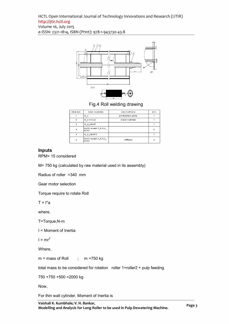
Fig.4 Roll welding drawing
Inputs RPM= 15 considered
M= 750 kg (calculated by raw material used in its assembly)
Radius of roller =340 mm
Gear motor selection
Torque require to rotate Roll
T = I*a
where,
T=Torque,N-m
I = Moment of Inertia
I = mr2
Where,
m = mass of Roll ; m =750 kg
total mass to be considered for rotation roller 1+roller2 + pulp feeding
750 +750 +500 =2000 kg
Now,
For thin wall cylinder, Moment of Inertia is

HCTL Open International Journal of Technology Innovations and Research (IJTIR) http://ijtir.hctl.org Volume 16, July 2015 e-ISSN: 2321-1814, ISBN (Print): 978-1-943730-43-8
Vaishali K. Kumbhale; V. H. Bankar, Modelling and Analysis for Long Roller to be used in Pulp Dewatering Machine.
Page 4
I = mr2 = 2000x 0.3402= 231
= 231 kg.m2
a=AngularAcceleration,rad/sec^2
We have,
N=15 rpm
V = π DN / 60,000
= 0.53 m/sec
Angular velocity, ω = v / r = 1.6 rad / sec
ω = θ / t
where,
θ = 1 revolution = 3600 = 2π rad
t = time in sec.
t = θ / ω = 3.9= ~ 4 sec
Angular acceleration,
a = ω / t = 0.4 rad / sec2
Torque required to rotate the roll
T = I x a
= 231 x 0.4 = 92.4 N-m
Power = 2πNT / 60000
= 0.145 kW
Fig.5 Shear Stress in the Shaft

HCTL Open International Journal of Technology Innovations and Research (IJTIR) http://ijtir.hctl.org Volume 16, July 2015 e-ISSN: 2321-1814, ISBN (Print): 978-1-943730-43-8
Vaishali K. Kumbhale; V. H. Bankar, Modelling and Analysis for Long Roller to be used in Pulp Dewatering Machine.
Page 5
Fig.6. Similar on another side
When a shaft is subjected to a torque or twisting, shearing stress is produced in the
shaft. The shear stress varies from zero in the axis to a maximum at the outside
surface of the shaft in the shaft. The shear stress varies from zero in the axis to a
maximum at the outside surface of the shaft.
Stresses in the shaft used to rotate the roller body
The shaft is subjected to twisting moment
Torque acting is T = 900 Nm = 900 x 103Nmm
Outer diameter of shaft (Do) = 130 mm
Inner diameter of shaft (Di) = 90 mm
We have the torsion equation,

HCTL Open International Journal of Technology Innovations and Research (IJTIR) http://ijtir.hctl.org Volume 16, July 2015 e-ISSN: 2321-1814, ISBN (Print): 978-1-943730-43-8
Vaishali K. Kumbhale; V. H. Bankar, Modelling and Analysis for Long Roller to be used in Pulp Dewatering Machine.
Page 6
Where,
T = Torque (Nmm) J = Polar moment inertia (mm4) R = outer radius (mm) τ = Shear stress (n/mm2) Hence, Shear stress is given by,
Polar moment of inertia,
J = 21.6 x 106 mm4
Hence Shear stress is
τ = 2.8 N/mm2 τ = ~ 3 MPa Also from torsion equation, we have
Where,
G = modulus of rigidity (N/mm2) θ= Angle of twist (Rad) L = length of shaft For Steel, G = 80 GPa = 80 x 103 N/mm2 Length of shaft (L) = 810mm
=
= 0.0004 radian 0.0250
Hence maximum angular deflection in the shaft is 0.0250.
Roller parameters DiaOD 570 mm ID 550 mm , since 10 mm thich plate is used to form cylindrical roller structure in weldment form. When the material (pulp) passes between the roller gap, it applies the force on the roller. Hence the roller is subjected to combined twisting moment and bending moment. According to American Society of Mechanical Engineers (ASME) code for the design of transmission shaft the maximum permissible bendingstress (σ) may be taken as σ = 0.6σel or 0.36σut whichever is less. Hence σ = 0.6 x 215 = 129 MPa For bending moment, we have from flexure formula,
.........(i)
Where, M = bending moment I = moment of inertia I = 689.86 x 106 mm4
σ = permissible bending stress = 129 N/mm2 y = D0 / 2 = 285 mm

HCTL Open International Journal of Technology Innovations and Research (IJTIR) http://ijtir.hctl.org Volume 16, July 2015 e-ISSN: 2321-1814, ISBN (Print): 978-1-943730-43-8
Vaishali K. Kumbhale; V. H. Bankar, Modelling and Analysis for Long Roller to be used in Pulp Dewatering Machine.
Page 7
From eq.(i) M = (129 x 689.86 x 〖10〗^6))/285 M = 312.25 x 10⁶Nmm
According to American Society of Mechanical Engineers (ASME) code for the design of transmission shaft the maximum permissible shear stress (τ) may be taken as 18% of ultimate tensile strength (σut). In other words, τ = 0.18 σut Maximum permissible shear stress, τ = 0.18 σut = 0.18 x 520 = 93.6 MPa From torsional equation we have
Where, T = torque acting on the shaft j = polar moment of inertia τ = torsional shear stress R = Distance from neutral axis to outermost fibre = D0/2.... where D is diameter of the shaft = 285 mm We know that, for solid circular shaft, polar moment inertia (j) is given by, j= π/32 (〖D_0〗^4-〖D_i〗^4 ) J = 1379.72 x 106 mm4 Now, the Shear stress is τ = 0.3 σel = 0.3 x 205 = 61.5 MPa Hence, Twisting moment, T = 297.73 x 10⁶ N mm According to maximum shear stress theory, Maximum shear stress τmax = (16D_0)/(π(〖D_0〗^4-〖D_i〗^4)) T_e where, Te= √(M2+T2) Te= 431.44 x 10⁶Nmm
Hence Maximum shear stress, τmax=89.12 N/mm2
= 0.0059 radian 0.340
Hence maximum angular deflection in the roller body is 0.340.
(Reference:A textbook of Machine Design by R. S. Khurmi and J. K. Gupta, S. Chand
Publication, (14th edition))
HCTL Open International Journal of Technology Innovations and Research (IJTIR) http://ijtir.hctl.org Volume 16, July 2015 e-ISSN: 2321-1814, ISBN (Print): 978-1-943730-43-8
Vaishali K. Kumbhale; V. H. Bankar, Modelling and Analysis for Long Roller to be used in Pulp Dewatering Machine.
Page 8
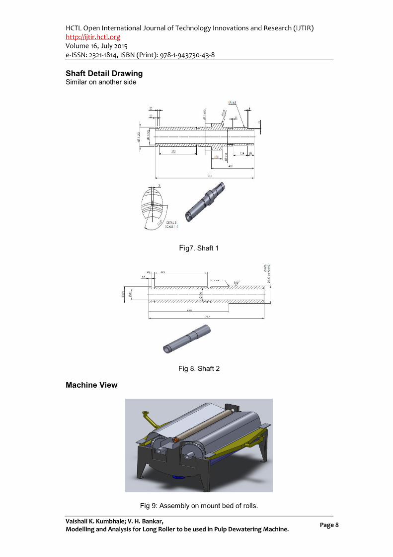
Shaft Detail Drawing Similar on another side
Fig7. Shaft 1
Fig 8. Shaft 2
Machine View
Fig 9: Assembly on mount bed of rolls.

HCTL Open International Journal of Technology Innovations and Research (IJTIR) http://ijtir.hctl.org Volume 16, July 2015 e-ISSN: 2321-1814, ISBN (Print): 978-1-943730-43-8
Vaishali K. Kumbhale; V. H. Bankar, Modelling and Analysis for Long Roller to be used in Pulp Dewatering Machine.
Page 9
Analysis
Structural strength assessment on component
Fig10.Model is taken from CAD module ,Imported model is taken for ansys input.
Fig.11 Meshing of roll assembly.
Tetrahedron mesh is selected as its usually taken by ansys for material AISI304
Fig.12. Loading / Boundary conditions
Roller affect deflection without covering flanges 0.00381 mm max deflection found
HCTL Open International Journal of Technology Innovations and Research (IJTIR) http://ijtir.hctl.org Volume 16, July 2015 e-ISSN: 2321-1814, ISBN (Print): 978-1-943730-43-8
Vaishali K. Kumbhale; V. H. Bankar, Modelling and Analysis for Long Roller to be used in Pulp Dewatering Machine.
Page 10
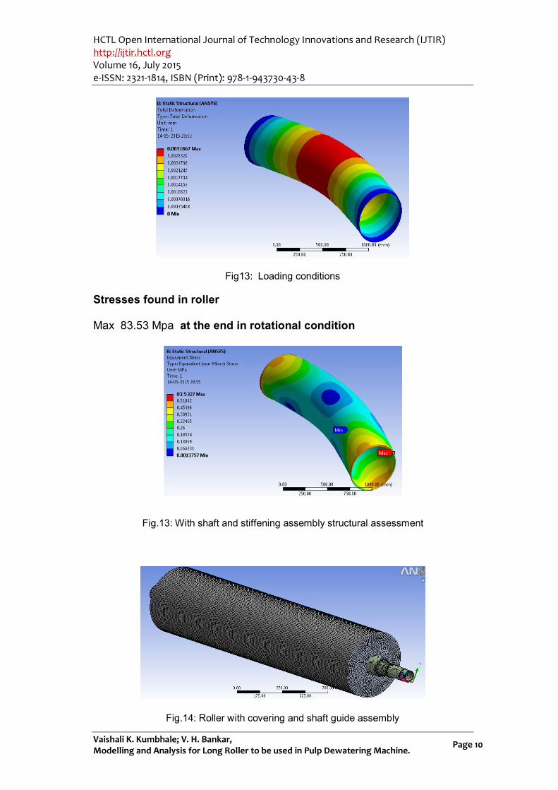
Fig13: Loading conditions
Stresses found in roller
Max 83.53 Mpa at the end in rotational condition
Fig.13: With shaft and stiffening assembly structural assessment
Fig.14: Roller with covering and shaft guide assembly

HCTL Open International Journal of Technology Innovations and Research (IJTIR) http://ijtir.hctl.org Volume 16, July 2015 e-ISSN: 2321-1814, ISBN (Print): 978-1-943730-43-8
Vaishali K. Kumbhale; V. H. Bankar, Modelling and Analysis for Long Roller to be used in Pulp Dewatering Machine.
Page 11
Fig: Meshing mode
Fig: Loading conditions
Total deformation : 0.0083742 mm
Stress max = 6.53 Mpa
HCTL Open International Journal of Technology Innovations and Research (IJTIR) http://ijtir.hctl.org Volume 16, July 2015 e-ISSN: 2321-1814, ISBN (Print): 978-1-943730-43-8
Vaishali K. Kumbhale; V. H. Bankar, Modelling and Analysis for Long Roller to be used in Pulp Dewatering Machine.
Page 12
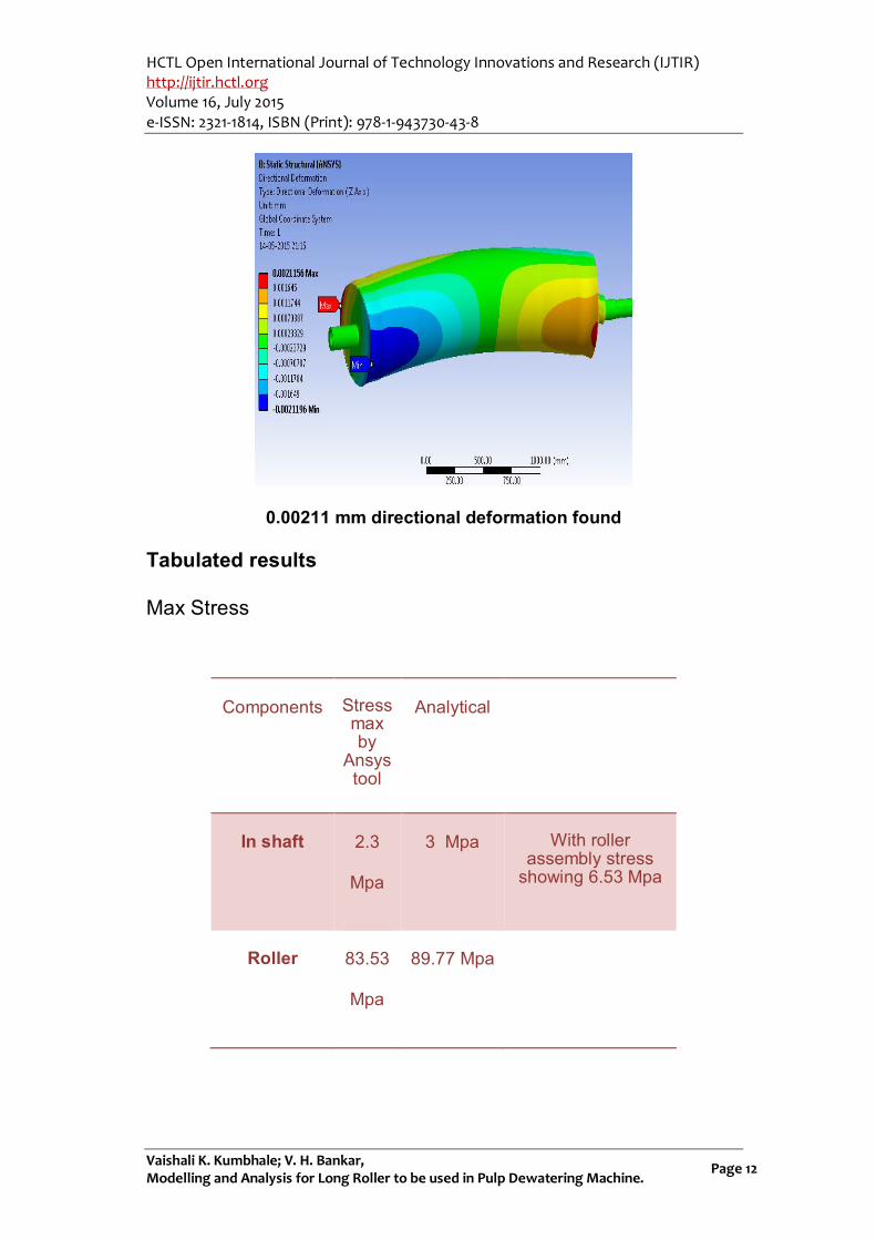
0.00211 mm directional deformation found
Tabulated results
Max Stress
Components Stress max by
Ansys tool
Analytical
In shaft 2.3
Mpa
3 Mpa With roller assembly stress
showing 6.53 Mpa
Roller 83.53
Mpa
89.77 Mpa
HCTL Open International Journal of Technology Innovations and Research (IJTIR) http://ijtir.hctl.org Volume 16, July 2015 e-ISSN: 2321-1814, ISBN (Print): 978-1-943730-43-8
Vaishali K. Kumbhale; V. H. Bankar, Modelling and Analysis for Long Roller to be used in Pulp Dewatering Machine.
Page 13
Conclusion
As prescribed assembly of roll is feasible to make long rotary cylindrical roll for required boundry loads .
References
[1] Twin roll strip casting of magnesium D.Liang and C.B.Cowle
[2] Design of a Composite Roll with Internal Cooling Channels for Twin-Roll Casting Ian Stone,Brian, Mckay and Zhongyun Fan. [3] Corrosion damage assessment and burst test validation of 8in X52 line pipe Annette D Karstensen and Alan T Smith Structural Integrity Technology Group TWI Ltd Great Abington Cambridge CB1 6AL,UK. [4] High Pressure Grinding Roller Presses [5] Design and Calculation (References: A textbook of Machine Design By R. S. Khurmi and J. K. Gupta, S.Chand Publication,14thB.D.Shewalkar Design Data Book. [6] Alfa combustion chamber and oxidizing tank By Ryan Pulkrabek. [7] http://www.main-switzerland.com/mainstrip/mainstrip-twin-roll-casting [8] http://link.springer.com/article/10.1007%2Fs11837-004-0122-6#page-1 [9] Rajashree S. Pawar; V. H. Bankar, Modelling and Analysis of Vertical Rotary Automated Drilling Fixture, HCTL Open International Journal of Technology Innovations and Research (IJTIR), Volume 16, July 2015, e-ISSN: 2321-1814, ISBN: 978-1-943730-43-8.
This article is an open access article distributed under the terms and conditions of
the Creative Commons Attribution 4.0 International License (https://creativecommons.org/licenses/by/4.0/).
© 2015 by the Authors. Licensed by HCTL Open, India.


![To love ru vol16 [haru ka]](https://img.pdfslide.us/doc/110x75/568cada61a28ab186dac8cf5/to-love-ru-vol16-haru-ka.jpg)